WO2014017341A1 - Dispositif d'affichage équipé d'une fonction de génération d'énergie - Google Patents
Dispositif d'affichage équipé d'une fonction de génération d'énergie Download PDFInfo
- Publication number
- WO2014017341A1 WO2014017341A1 PCT/JP2013/069341 JP2013069341W WO2014017341A1 WO 2014017341 A1 WO2014017341 A1 WO 2014017341A1 JP 2013069341 W JP2013069341 W JP 2013069341W WO 2014017341 A1 WO2014017341 A1 WO 2014017341A1
- Authority
- WO
- WIPO (PCT)
- Prior art keywords
- electrode
- display device
- power generation
- generation function
- external battery
- Prior art date
- Legal status (The legal status is an assumption and is not a legal conclusion. Google has not performed a legal analysis and makes no representation as to the accuracy of the status listed.)
- Ceased
Links
Images

















Classifications
-
- G—PHYSICS
- G09—EDUCATION; CRYPTOGRAPHY; DISPLAY; ADVERTISING; SEALS
- G09G—ARRANGEMENTS OR CIRCUITS FOR CONTROL OF INDICATING DEVICES USING STATIC MEANS TO PRESENT VARIABLE INFORMATION
- G09G3/00—Control arrangements or circuits, of interest only in connection with visual indicators other than cathode-ray tubes
- G09G3/20—Control arrangements or circuits, of interest only in connection with visual indicators other than cathode-ray tubes for presentation of an assembly of a number of characters, e.g. a page, by composing the assembly by combination of individual elements arranged in a matrix no fixed position being assigned to or needed to be assigned to the individual characters or partial characters
- G09G3/34—Control arrangements or circuits, of interest only in connection with visual indicators other than cathode-ray tubes for presentation of an assembly of a number of characters, e.g. a page, by composing the assembly by combination of individual elements arranged in a matrix no fixed position being assigned to or needed to be assigned to the individual characters or partial characters by control of light from an independent source
- G09G3/3433—Control arrangements or circuits, of interest only in connection with visual indicators other than cathode-ray tubes for presentation of an assembly of a number of characters, e.g. a page, by composing the assembly by combination of individual elements arranged in a matrix no fixed position being assigned to or needed to be assigned to the individual characters or partial characters by control of light from an independent source using light modulating elements actuated by an electric field and being other than liquid crystal devices and electrochromic devices
-
- G—PHYSICS
- G02—OPTICS
- G02B—OPTICAL ELEMENTS, SYSTEMS OR APPARATUS
- G02B26/00—Optical devices or arrangements for the control of light using movable or deformable optical elements
- G02B26/02—Optical devices or arrangements for the control of light using movable or deformable optical elements for controlling the intensity of light
-
- G—PHYSICS
- G09—EDUCATION; CRYPTOGRAPHY; DISPLAY; ADVERTISING; SEALS
- G09G—ARRANGEMENTS OR CIRCUITS FOR CONTROL OF INDICATING DEVICES USING STATIC MEANS TO PRESENT VARIABLE INFORMATION
- G09G3/00—Control arrangements or circuits, of interest only in connection with visual indicators other than cathode-ray tubes
- G09G3/20—Control arrangements or circuits, of interest only in connection with visual indicators other than cathode-ray tubes for presentation of an assembly of a number of characters, e.g. a page, by composing the assembly by combination of individual elements arranged in a matrix no fixed position being assigned to or needed to be assigned to the individual characters or partial characters
-
- H—ELECTRICITY
- H02—GENERATION; CONVERSION OR DISTRIBUTION OF ELECTRIC POWER
- H02N—ELECTRIC MACHINES NOT OTHERWISE PROVIDED FOR
- H02N1/00—Electrostatic generators or motors using a solid moving electrostatic charge carrier
- H02N1/002—Electrostatic motors
- H02N1/006—Electrostatic motors of the gap-closing type
- H02N1/008—Laterally driven motors, e.g. of the comb-drive type
-
- G—PHYSICS
- G09—EDUCATION; CRYPTOGRAPHY; DISPLAY; ADVERTISING; SEALS
- G09G—ARRANGEMENTS OR CIRCUITS FOR CONTROL OF INDICATING DEVICES USING STATIC MEANS TO PRESENT VARIABLE INFORMATION
- G09G2300/00—Aspects of the constitution of display devices
- G09G2300/08—Active matrix structure, i.e. with use of active elements, inclusive of non-linear two terminal elements, in the pixels together with light emitting or modulating elements
-
- G—PHYSICS
- G09—EDUCATION; CRYPTOGRAPHY; DISPLAY; ADVERTISING; SEALS
- G09G—ARRANGEMENTS OR CIRCUITS FOR CONTROL OF INDICATING DEVICES USING STATIC MEANS TO PRESENT VARIABLE INFORMATION
- G09G2330/00—Aspects of power supply; Aspects of display protection and defect management
- G09G2330/02—Details of power systems and of start or stop of display operation
- G09G2330/021—Power management, e.g. power saving
-
- G—PHYSICS
- G09—EDUCATION; CRYPTOGRAPHY; DISPLAY; ADVERTISING; SEALS
- G09G—ARRANGEMENTS OR CIRCUITS FOR CONTROL OF INDICATING DEVICES USING STATIC MEANS TO PRESENT VARIABLE INFORMATION
- G09G2330/00—Aspects of power supply; Aspects of display protection and defect management
- G09G2330/02—Details of power systems and of start or stop of display operation
- G09G2330/021—Power management, e.g. power saving
- G09G2330/023—Power management, e.g. power saving using energy recovery or conservation
Definitions
- the present invention relates to a display device with a power generation function. More specifically, the present invention relates to a shutter display using MEMS (Micro Electro-Mechanical System) technology.
- MEMS Micro Electro-Mechanical System
- MEMS technology has attracted attention as a technology for manufacturing minute electronic components, and is being studied for use in electronic devices such as displays and power generation devices (see, for example, Patent Documents 1 and 2).
- a display manufactured using the MEMS technology includes a MEMS shutter display.
- the display has a minute shutter manufactured by using MEMS technology for each pixel, and by opening and closing the shutter, the amount of light transmitted from a backlight or the like is adjusted, and the display is turned on / off. .
- the display does not require a polarizing plate, a color filter, and the like that are necessary for liquid crystal displays that are currently mainstream, and thus has high light utilization efficiency and low power consumption.
- the MEMS shutter display consumes less power than a liquid crystal display, there is still room for study on a method for reducing the power consumption.
- the display consumes electric power, and an external battery or a power generator for supplying electric power for driving the display is required.
- the present invention has been made in view of the above situation, and an object of the present invention is to provide a MEMS shutter type display device with a power generation function that not only suppresses power consumption but also has a power generation function.
- the inventor examined a method for reducing power consumption of a MEMS shutter display, and focused on the driving principle of the display. Then, since the display performs display by opening and closing the shutter at a high speed, it is considered that it is difficult to avoid the power required to drive the shutter portion, and further examination was made on a method of reducing power consumption from another approach.
- the inventor of the present invention pays attention to the fact that the display is charged positively or negatively, and that the display is operated by moving the shutter left and right, and uses the movement of the shutter. And found that it can generate electricity.
- the power generation electrode is charged to a polarity opposite to that of the shutter portion. Furthermore, the amount of charge charged to the power generation electrode changes due to the change in the distance between the power generation electrode and the shutter portion in accordance with the operation of the shutter portion, and the current corresponding to the amount of change in the charge changes. And found that it can be removed from the power generation electrode and reused.
- the driving of the shutter unit can be used not only as a display device but also as a power generation mechanism, and the generated electromotive force can be used as, for example, a part of a power source in a driving circuit. Therefore, the power consumption of the entire display can be suppressed.
- the present inventor has arrived at the present invention, conceiving that the above-mentioned problems can be solved brilliantly.
- a movable first shutter portion including a first slit, a first electrode, and a first electrode on the opposite side of the first electrode across the first shutter portion.
- the drive circuit is a display device with a power generation function connected to the first electrode (hereinafter also referred to as the first display device of the present invention).
- the display device includes a first substrate and a second substrate.
- the first substrate has a first shutter part including a first slit
- the second substrate has a second shutter part including a second slit.
- the first shutter unit is movable and is positively or negatively charged, and includes, for example, an electret.
- An electret is a material in which a dielectric is charged and fixed, and the operation of charging a dielectric with a charge is called electretization.
- transmission and blocking of light from the light source are controlled according to the degree of overlap between the first slit and the second slit.
- the display device includes a first electrode and a second electrode.
- the first electrode is a part that is connected to the drive circuit and receives a predetermined potential from the drive circuit, and is used for the operation of the movable first shutter unit.
- the second electrode is used to supply a new electromotive force to the power source by utilizing the movement of electric charges generated by the movement of the first shutter unit.
- the first shutter unit when the first shutter unit is negatively charged, when a negative potential is supplied from the drive circuit to the first electrode, the first shutter unit is placed between the first electrode and the shutter unit. Electrostatic force (Coulomb force) works and repulsion occurs. The shutter portion moves away from the first electrode by the repulsive force. At this time, in the second electrode provided at a certain distance from the first shutter part, electrostatic induction occurs when the first shutter part approaches, and positive charges concentrate on the second electrode. , Charge transfer (current) occurs. Thereafter, when the potential supplied from the driving circuit to the first electrode is switched, the first shutter portion returns to the original position by the restoring force of the elastic body. At this time, in the second electrode, electrostatic induction occurs when the first shutter portion moves away, negative charges concentrate on the second electrode, and charge movement (current) occurs.
- Electrostatic force Coulomb force
- the longitudinal direction of the first slit and the longitudinal direction of the second slit are preferably parallel.
- the first and second slits are not particularly limited in shape and size as long as the longitudinal directions are parallel to each other.
- the first shutter portion is moved by an electrostatic force between the first shutter portion and the first electrode.
- an electromotive force is generated in the second electrode by electrostatic induction generated by the movement of the first shutter portion.
- the second electrode is connected to the drive circuit, for example. Thereby, the electromotive force generated in the second electrode can be supplied to the power supply in the drive circuit.
- a rectifier circuit is preferably provided between the second electrode and the drive circuit.
- the display device with a power generation function further includes a light source, and controls the display by adjusting the amount of light emitted from the light source to the outside of the display device by the first and second shutter portions. Can do.
- the second electrode may be connected to the light source, whereby the electromotive force generated in the second electrode can be supplied to the light source.
- a rectifier circuit is preferably provided between the second electrode and the light source.
- the display device with a power generation function may further include an external battery, and the second electrode may be connected to the external battery.
- the second electrode and the external battery are connected in series, and the external battery is connected to the drive circuit and / or the light source, and the external battery is preferably a secondary battery.
- the generated electromotive force can be stored in the secondary battery using vibration (environmental vibration) from the outside of the display device.
- the display device can be driven without the need for a power generation device that supplies power.
- the second electrode and the external battery are connected in series, it is preferable that a rectifier circuit is provided between the second electrode and the external battery. Thereby, the electromotive force generated at the second electrode can be efficiently supplied to the power source.
- the above-described effects can be obtained even if the second shutter portion is the second electrode.
- another aspect of the present invention provides a movable first shutter unit including a first slit, a first substrate having a first electrode, and a second shutter unit including a second slit.
- the same form as that described as the preferable form of the first display device of the present invention can be cited. That is, as a preferable form of the second display device of the present invention,
- the first shutter unit is moved by electrostatic force between the first electrode and the first electrode, (C) a mode in which an electromotive force is generated in the second electrode by electrostatic induction generated by the movement of the first shutter unit; (D) the second electrode is connected to the drive circuit; (E) a form in which a rectifier circuit is provided between the second electrode and the drive circuit; (F)
- the display device with a power generation function further includes a light source, and an amount in which light from the light source is emitted outside the display device is adjusted by the first and second shutter portions, (G) The second electrode is connected to the light source, (H) a form in which a rectifier circuit is provided between the second electrode and the light source; (I)
- the display device with a power generation function further includes an external battery, and the second electrode is connected to the external battery, (J) The second electrode and the external battery are connected in series, and a rectif
- the above-described effects can be obtained even when the third electrode is provided in addition to the second electrode.
- an electromotive force can be supplied to each of the drive circuit and the light source through separate circuits.
- another aspect of the present invention provides a movable first shutter portion including a first slit, a first electrode, and an opposite side of the first electrode across the first shutter portion.
- the shutter unit is charged positively or negatively, the second shutter unit is a third electrode, and the drive circuit is a display device with a power generation function (hereinafter referred to as the first electrode). , Also referred to as a third display device of the present invention).
- the third electrode is used to supply a new electromotive force to a power source in the drive circuit, for example, using the movement of electric charges generated by the movement of the first shutter unit, similarly to the second electrode. .
- the same form as that described as the preferable form of the first display device of the present invention can be mentioned. That is, as a preferable form of the third display device of the present invention, (L) a form in which the longitudinal direction of the first slit and the longitudinal direction of the second slit are parallel; (M) The first shutter portion is moved by electrostatic force between the first electrode and the first electrode, (N) a mode in which an electromotive force is generated in the second electrode and the third electrode due to electrostatic induction generated by the movement of the first shutter unit; (O) a mode in which at least one of the second electrode and the third electrode is connected to the drive circuit; (P) A form in which a rectifier circuit is provided between the second electrode and the drive circuit, and a form in which a rectifier circuit is provided between the third electrode and the drive circuit.
- the display device with a power generation function further includes a light source, and an amount in which light from the light source is emitted to the outside of the display device is adjusted by the first and second shutter portions, (R) At least one of the second electrode and the third electrode is connected to the light source, (S) a form in which a rectifier circuit is provided between the second electrode and the light source, and a form in which a rectifier circuit is provided between the third electrode and the light source, (T)
- the display device with a power generation function further includes an external battery (hereinafter also referred to as a first external battery), and the second electrode is connected to the first external battery.
- the display device with a power generation function further includes an external battery (hereinafter also referred to as a second external battery), and the third electrode is connected to the second external battery.
- the second electrode and the first external battery are connected in series, and a rectifier circuit is provided between the second electrode and the first external battery
- (W) The third electrode and the second external battery are connected in series, and a rectifier circuit is provided between the third electrode and the second external battery
- the display device with a power generation function further includes an external battery (hereinafter also referred to as a third external battery), and the second electrode and the third electrode are connected in parallel.
- the second electrode and the third electrode and the third external battery are connected in series, and the third external battery is connected to the drive circuit and / or the light source, and
- the third external battery may be a secondary battery.
- the display apparatus with a power generation function of the MEMS shutter type which suppressed power consumption can be provided.
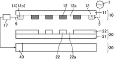
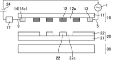
- FIG. 3 is a schematic cross-sectional view of one pixel of the display device according to the first embodiment.
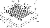
- FIG. 2 is a schematic perspective view of one pixel of the first substrate shown in FIG. 1.
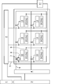
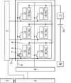
- FIG. 3 is a drive circuit diagram of the display device according to the first embodiment.
- FIG. 3 is a schematic cross-sectional view when a voltage for one pixel of the display device according to the first embodiment is not applied.
- FIG. 3 is a schematic cross-sectional view when a negative voltage for one pixel of the display device according to the first embodiment is applied.
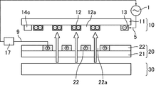
- FIG. 10 is a schematic cross-sectional view of one pixel of a display device according to Modification 1.
- FIG. 10 is a schematic cross-sectional view of one pixel of a display device according to Modification 1.
- FIG. 11 is a drive circuit diagram of a display device according to Modification Example 1.
- FIG. 6 is a schematic cross-sectional view of one pixel of a display device according to a second embodiment.
- FIG. 4 is a drive circuit diagram of a display device according to a second embodiment.
- FIG. 10 is a schematic cross-sectional view when a voltage for one pixel of the display device according to the third embodiment is not applied.
- FIG. 10 is a schematic cross-sectional view when a negative voltage for one pixel of the display device according to the third embodiment is applied.
- FIG. 6 is a drive circuit diagram of a display device according to a third embodiment.
- FIG. 14 is a schematic cross-sectional view of one pixel of a display device according to Modification 3.
- FIG. 11 is a drive circuit diagram of a display device according to Modification 3.
- FIG. 10 is a schematic cross-sectional view when a voltage for one pixel of the display device according to the fourth embodiment is not applied.
- FIG. 10 is a schematic cross-sectional view when a negative voltage for one pixel of the display device according to the fourth embodiment is applied.
- FIG. 6 is a drive circuit diagram of a display device according to a fourth embodiment.
- FIG. 10 is a drive circuit diagram of a display device according to Modification 4-1.
- FIG. 16 is a drive circuit diagram of a display device according to Modification 4-2.
- FIG. 6 is a schematic cross-sectional view of one pixel of a display device according to a fifth embodiment.
- FIG. 6 is a drive circuit diagram of a display device according to a fifth embodiment.
- FIG. 14 is a drive circuit diagram of a display device according to Modification 5-1.
- FIG. 16 is a drive circuit diagram of a display device according to Modification 5-2.
- FIG. 10 is a drive circuit diagram of a display device according to Modification 5-3.
- FIG. 7 is a schematic cross-sectional view of one pixel of a display device according to a sixth embodiment.
- FIG. 7 is a drive circuit diagram of a display device according to a sixth embodiment.
- FIG. 16 is a drive circuit diagram of a display device according to Modification 6-1.
- FIG. 16 is a drive circuit diagram of a display device according to Modification 6-2.
- FIG. 10 is a schematic cross-sectional view when a voltage for one pixel of the display device according to the seventh embodiment is not applied.
- FIG. 10 is a schematic cross-sectional view when a negative voltage for one pixel of a display device according to a seventh embodiment is applied.
- FIG. 10 is a schematic cross-sectional view of one pixel of a display device according to an eighth embodiment.
- FIG. 10 is a schematic cross-sectional view when a voltage for one pixel of a display device according to Embodiment 9 is not applied.
- FIG. 10 is a schematic cross-sectional view when a negative voltage for one pixel of a display device according to Embodiment 9 is applied.
- the illustration of the 1st slit and 2nd slit which the display apparatus which concerns on Embodiment 10 has.
- FIG. 1 is a schematic cross-sectional view of one pixel of the display device according to the first embodiment.
- 2 is a schematic perspective view of one pixel of the first substrate shown in FIG. 1
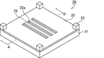
- FIG. 3 is a schematic perspective view of one pixel of the second substrate shown in FIG. A and B shown in FIGS. 1 to 3 correspond to each other.
- FIG. 4 is a drive circuit diagram of the display device according to the first embodiment.
- the display device includes a first substrate 10, a second substrate 20, and a backlight unit 30 in this order from the observation surface side to the back surface side.
- the first substrate 10 has a shutter part (first shutter part) 12, and the second substrate 20 has a shutter part (second shutter part) 22.
- the shutter unit 12 is movable, and when not displayed, the shutter unit 12 overlaps with the slit of the shutter unit 22 and the light from the backlight unit 30 is blocked.
- the slit of the shutter unit 12 and the slit of the shutter unit 22 overlap, and light from the backlight unit 30 passes through each slit and is emitted as display light.
- the first substrate 10 includes a transparent substrate 11, a shutter part (first shutter part) 12, a first electrode 13, and a plurality of supports that support the shutter part 12. 14.
- the shutter unit 12 has a plurality of slits (first slits) 12a inside, and the outer edge when viewed in plan is a quadrangle (rectangle).
- the shutter unit 12 can reciprocate in the horizontal direction using the expansion and contraction of the first elastic body 15 and the second elastic body 16.
- the first electrode 13 is connected to the power source 1 in the drive circuit, and is electrically isolated from the shutter unit 12.
- the support functions as the second electrode 14.
- the second electrode 14 is electrically connected to the power supply 1 in the drive circuit via the charge electrode 9 and the rectifier circuit 17.
- the support 14c on the opposite side of the first electrode with the shutter portion interposed therebetween is used as the second electrode.
- the material of the second electrode 14 include aluminum (Al), tungsten (W), and the like, and copper (Cu) or silver (Ag) having a low electric resistance is preferably used.
- the shutter unit 12 is charged positively or negatively, and for example, an electret is used.
- the electretization can be performed by, for example, corona discharge.
- Dielectric materials suitable for electretization include polymer materials such as Teflon (registered trademark), polypropylene, and mylar, and silicon oxide materials such as TEOS (Tetra Ethylene Oxy Silane) and SiOF (Fluorine-doped Silicon Oxide). Materials.
- the shutter unit 12 is made of a light shielding material or a transparent material in which a light shielding component such as a resin BM is dispersed.
- the amount of light transmitted from the backlight unit 30 can be adjusted by the shutter unit 12 having a light shielding property.
- the shape of the first elastic body 15 and the second elastic body 16 is not particularly limited as long as the first elastic body 15 and the second elastic body 16 have stretchability.
- the material may be a conductive material or a dielectric material. Good. Since both ends of the shutter portion 12 are fixed via an elastic body, the slid shutter portion 12 can be returned to the original position by the restoring force of the elastic body, as will be described later.
- the first electrode 13 is connected to the source driver of the drive circuit, and a positive or negative potential is supplied from the power supply 1. Thereby, a Coulomb force is generated between the first electrode 13 and the negatively charged shutter portion 12, and the shutter portion 12 can be translated in the horizontal direction.
- the material of the first electrode 13 include aluminum (Al), tungsten (W), and the like, similarly to the second electrode 14, and copper (Cu) or silver (Ag) having a low electric resistance is preferably used. .
- the second substrate 20 includes a transparent substrate 21 and a shutter part (second shutter part) 22, and the shutter part 22 includes a plurality of slits (second slits) therein. ) 22a
- the shutter unit 22 is made of a light-shielding material or a transparent material in which a light-shielding component such as a resin BM is dispersed.
- Spacers 23 for separating a certain distance between the shutter portion 12 and the shutter portion 22 are disposed at the four corners of a region (rectangle) corresponding to one pixel of the second substrate.
- the backlight unit 30 includes optical members such as a light source, a light guide plate, and an optical sheet.
- a light source that emits intrinsic light such as red, green, and blue is preferably used.
- the light source that emits intrinsic light such as red, green, and blue include a light emitting diode (LED).
- LED light emitting diode
- Examples of other light sources include a cold cathode fluorescent lamp (CCFL). In this case, it is necessary to dispose a color filter.
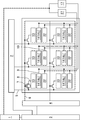
- a drive circuit of the display device according to the first embodiment will be described with reference to FIG.
- the power source 1 is connected to the display control circuit 3, and the display control circuit 3 is connected to the source driver 2 and the gate driver 4.
- a series of circuits used for display control of the power supply 1, the display control circuit 3, the source driver 2, the gate driver 4, and the like correspond to the “drive circuit” in the present invention.
- a plurality of source lines 5 are drawn from the source driver 2, and a plurality of gate lines 6 are drawn from the gate driver 4.
- the source wiring 5 and the gate wiring 6 are extended so as to cross each other, and a region surrounded by the source wiring 5 and the gate wiring 6 is one pixel.
- a TFT 7 is provided at each intersection of the source wiring 5 and the gate wiring 6.
- a drain wiring 8 is drawn out from the TFT 7, and the drain wiring 8 is connected to the first electrode 13.
- the second electrode 14 provided for each pixel is connected to the charge electrode 9 common to each pixel, and is connected to the power supply 1 via the rectifier circuit 17.
- the rectifier circuit 17 is a circuit including a commutator (for example, a diode). By providing the rectifier circuit 17 between the second electrode 14 and the power source 1, the supply from the second electrode 14 to the power source 1 can be performed efficiently.
- a commutator for example, a diode
- the electromotive force generated by the operation of the shutter unit 12 can be used as a part of the power source 1.
- the transparent substrates 11 and 21 are support substrates, and a transparent insulator material such as glass or plastic is preferably used.
- the source wiring 5, the gate wiring 6, the electrode of the TFT 7, and the charge electrode 9 are made of, for example, a metal such as titanium (Ti), chromium (Cr), aluminum (Al), molybdenum (Mo), etc. by sputtering or the like.
- the alloy can be formed by forming a single layer or a plurality of layers using a sputtering method or the like and then patterning the layer using a photolithography method or the like.
- the shutter part 12, the 1st electrode 13, the 2nd electrode 14, the 1st elastic body 15, and the 2nd elastic body 16 can be produced by MEMS technology using each material. .
- a display device By laminating the first substrate 10 and the second substrate 20 in which each of the above members are built, and further mounting a gate driver, a source driver, a display control circuit, etc. on the substrate, and combining a backlight unit, A display device according to the application is completed.
- FIGS. 5 and 6 are cross-sectional schematic diagrams for one pixel of the display device according to the first embodiment.
- FIG. 5 illustrates a case where no voltage is applied
- FIG. 6 illustrates a case where a negative voltage is applied.
- the slit 12a and the slit 22a are completely overlapped, and light from the backlight unit 30 is transmitted through the slits 12a and 22a.
- the display has the highest luminance (white display).
- the second electrode 14 When the shutter unit 12 slides to the left, the distance between the second electrode 14 that is a support of the shutter unit 12 and the shutter unit 12 approaches, electrostatic induction occurs, and the second electrode 14 is connected to the shutter unit 12. Charge to the opposite polarity. In the example shown in FIG. 6, since the shutter part 12 is negatively charged, the second electrode 14 is positively charged.
- the shutter unit 12 returns to the original position by the restoring force of the first elastic body 15.
- the amount of charge charged in the second electrode 14 changes, and a current flows through the charge electrode 9. Since the charge electrode 9 is connected to the power source 1 in the drive circuit via the rectifier circuit 17 or the like, the generated electromotive force can be used as a part of the power source in the drive circuit.
- the gradation display on the MEMS display is a unit of light emitted from the backlight by adjusting the amount of light transmitted according to the degree of overlap between the shutter unit 12 and the slit 22a, or by sliding the shutter unit 12 at high speed. This is achieved by adjusting the amount of transmission per hour.
- the shutter unit 12 may be positively charged and a positive potential may be supplied to the first electrode.
- FIG. 7 is a schematic cross-sectional view for one pixel of the display device according to the first modification
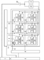
- FIG. 8 is a drive circuit diagram of the display device according to the first modification.
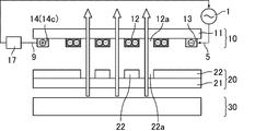
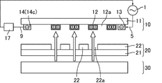
- the second electrode 14 is connected to the light source 40 in the backlight unit via the charge electrode 9 and the rectifier circuit 17.
- the electromotive force generated by driving the first shutter unit can be used as a part of the light source.
- the shutter unit 12 slides to the left and right as shown in FIGS. 5 and 6 in accordance with the switching of the potential supplied to the first electrode, and performs power generation simultaneously with display. Can do. Since the generated electromotive force can be used as a part of the power source and / or light source in the drive circuit, the power consumption of the entire display device can be suppressed.
- FIG. 9 is a schematic cross-sectional view of one pixel of the display device according to the second embodiment
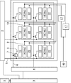
- FIG. 10 is a drive circuit diagram of the display device according to the second embodiment.
- the second electrode 14, the charge electrode 9, the rectifier circuit 17, the external battery 24, and the power source 1 are connected in series in this order.
- a secondary battery is used as the external battery 24, and the type of the secondary battery is not particularly limited.
- the display of the display device according to the second embodiment is performed by adjusting the light transmission amount by the movement of the shutter unit 12 as in the first embodiment.
- power generation is performed using the movement of the shutter unit 12, which contributes to low power consumption.
- the external battery can be charged using vibration (environmental vibration) from the outside of the display device when the display is turned off. .
- vibration environmental vibration
- electrostatic induction occurs, and electric charge is supplied to the external battery 24 via the second electrode 14, the charge electrode 9 and the rectifier circuit 17, and charging is performed. It can be carried out.
- the electric charge accumulated in the external battery can be used as the electromotive force in the power supply in the drive circuit as it is when the display is turned on.
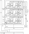
- FIG. 11 is a drive circuit diagram of a display device according to the second modification.
- the second electrode 14, the charge electrode 9, the rectifier circuit 17, the external battery 24, and the light source 40 in the backlight unit are connected in series in this order.
- vibration environmental vibration
- the external battery is charged using vibration (environmental vibration) from the outside of the display device, and the charge stored in the external battery remains unchanged when the display is turned on. It can be used in a light source as an electromotive force.
- the first shutter portion slides left and right in accordance with the switching of the potential supplied to the first electrode, and the power generation is performed simultaneously with the display. be able to. Furthermore, according to the second embodiment, charging is performed when display is not performed, and the charged power can be used as part of the power source and / or the light source in the drive circuit when displaying, so that more effective display can be performed. The power consumption of the entire apparatus can be suppressed.
- the third embodiment is the same as the first embodiment except that the second shutter portion is not the support that supports the first shutter but the second electrode is the second electrode.
- 12 and 13 are schematic cross-sectional views of one pixel of the display device according to the third embodiment.
- FIG. 12 shows a time when no voltage is applied, and 13 shows a time when a negative voltage is applied.
- FIG. 14 is a drive circuit diagram of the display device according to the third embodiment.
- the second shutter portion 22 is connected to the charge electrode 9 and functions as the second electrode.
- the charge electrode 9 is connected to the power source 1 in the drive circuit via the rectifier circuit 17.
- the basic point of the display principle is the same as that of the first embodiment. As shown in FIG. 12, when no voltage is applied, the slit 12a and the slit 22a are completely overlapped, and the light from the backlight unit 30 passes through these slits 12a and 22a.
- the display has the highest luminance (white display).
- the distance between the first shutter portion 12 and the second electrode 22 that is the second shutter portion is increased. Therefore, the second electrode 22 is charged by electrostatic induction. The positive charge that was stored decreases.
- the shutter unit 12 returns to the original position by the restoring force of the first elastic body 15.
- the distance between the shutter unit 12 and the second electrode 22 changes, the amount of charge charged in the second electrode 22 changes, and a current flows through the charge electrode 9. Since the charge electrode 9 is connected to the power source 1 in the drive circuit via the rectifier circuit 17, the generated electromotive force can be used as a part of the power source in the drive circuit.
- FIG. 15 is a schematic cross-sectional view of one pixel of the display device according to the third modification
- FIG. 16 is a drive circuit diagram of the display device according to the third modification.
- the second electrode 22 is connected to the light source 40 in the backlight unit via the charge electrode 9 and the rectifier circuit 17.
- the electromotive force generated by driving the first shutter unit can be used as a part of the light source.
- the first shutter unit slides to the left and right according to the switching of the potential supplied to the first electrode, and performs power generation simultaneously with display.
- the generated electromotive force can be used as a part of the power source and / or the light source in the driving circuit, the power consumption of the entire display device can be suppressed.
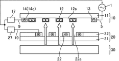
- FIGS. 17 and 18 are cross-sectional schematic diagrams for one pixel of the display device according to the fourth embodiment.
- FIG. 17 shows a time when no voltage is applied
- FIG. 18 shows a time when a negative voltage is applied.
- FIG. 19 is a drive circuit diagram of the display device according to the fourth embodiment.
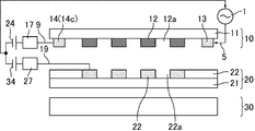
- the support 14c is connected to the charge electrode 9 and functions as the second electrode
- the second shutter portion 22 is connected to the charge electrode 19
- the third electrode Functions as an electrode.
- the charge electrode 9 is connected to the power source 1 of the drive circuit via the rectifier circuit 17
- the charge electrode 19 is connected to the power source 1 of the drive circuit via the rectifier circuit 27.
- FIG.17 and 18 The basic point of the display principle is the same as that of the first embodiment. As shown in FIG. 17, when no voltage is applied, the slit 12a and the slit 22a are completely overlapped, and light from the backlight unit 30 is transmitted through the slits 12a and 22a. The display has the highest luminance (white display).
- the shutter unit 12 slides to the left, the distance between the second electrode 14 that is a support of the shutter unit 12 and the shutter unit 12 approaches, electrostatic induction occurs, and the second electrode 14 is connected to the shutter unit 12. Charge to the opposite polarity. Further, since the distance between the first shutter portion 12 and the third electrode 22 which is the second shutter portion is increased, the positive charge charged in the second electrode 22 due to electrostatic induction is reduced.
- the shutter unit 12 returns to the original position by the restoring force of the first elastic body 15.
- the amount of charge charged in the second electrode 14 changes, and a current flows through the charge electrode 9.
- the amount of charge charged in the second electrode 22 changes, and a current flows through the charge electrode 19. Since the charge electrode 9 is connected to the power source 1 of the drive circuit via the rectifier circuit 17 and the charge electrode 19 is connected to the power source 1 of the drive circuit via the rectifier circuit 27, the generated electromotive force is It can be used as part of the power supply in the circuit.
- FIG. 20 is a drive circuit diagram of a display device according to Modification 4-1.
- the second electrode 14 is connected to the light source via the charge electrode 9 and the rectifier circuit 17, and the third electrode 22 is connected via the charge electrode 19 and the rectifier circuit 27. Connected to the light source.
- the electromotive force generated by driving the first shutter unit can be used as a part of the light source.
- FIG. 21 is a drive circuit diagram of a display device according to Modification 4-2.
- the second electrode 14 is connected to the power source 1 in the drive circuit via the charge electrode 9 and the rectifier circuit 17, and the third electrode 22 is connected to the charge electrode 19. And connected to the light source 40 via the rectifier circuit 27.
- the second electrode 14 may be connected to the light source 40, and the third electrode 22 may be connected to the power source 1 in the drive circuit.
- the electromotive force generated by driving the first shutter unit can be used in the power source and light source in the drive circuit.
- the shutter unit 12 slides to the left and right as shown in FIGS. 17 and 18 in accordance with the switching of the potential supplied to the first electrode, and performs power generation simultaneously with display. Can do. Furthermore, in the fourth embodiment, the second electrode and the third electrode both generate a new electromotive force in the power source and / or the light source of the driving circuit by using the movement of electric charges generated by the movement of the first shutter unit. Since it can supply, the power consumption as the whole electric power generation display apparatus can be suppressed more.
- FIG. 22 is a schematic cross-sectional view of one pixel of the display device according to the fifth embodiment
- FIG. 23 is a drive circuit diagram of the display device according to the fifth embodiment.
- the second electrode 14 and the third electrode 22 are connected in parallel, and the second electrode 14 is connected to the third electrode 22 via the charge electrode 9 and the rectifier circuit 17.
- the external battery 24 is connected to the power source 1 in the drive circuit.
- a secondary battery is used as the external battery 24, and the type of the secondary battery is not particularly limited.
- the electromotive force generated by driving the first shutter unit can be used as a part of the power supply in the drive circuit.
- the external battery is charged using vibration (environmental vibration) from the outside of the display device, and the charge accumulated in the external battery is stored when the display is turned on. It can be used as it is as an electromotive force in the power source in the drive circuit.
- FIG. 24 is a drive circuit diagram of a display device according to Modification 5-1.
- the second electrode 14 has the charge electrode 9, the rectifier circuit 17, the external battery 24, and the power source 1 connected in series in this order.
- the electrode 22 is connected to the power source 1 in the drive circuit without passing through the external battery 24.
- the third electrode 22 and the external battery 24 may be connected in series.
- the electromotive force generated by driving the first shutter unit can be used as part of the power supply in the drive circuit.
- the external battery is charged using vibration (environmental vibration) from the outside of the display device, and the charge accumulated in the external battery is stored when the display is turned on. It can be used as it is as an electromotive force in the power source in the drive circuit.
- FIG. 25 is a drive circuit diagram of a display device according to Modification 5-2.
- the second electrode 14 and the third electrode 22 are connected in parallel, and the second electrode 14 is connected via the charge electrode 9 and the rectifier circuit 17,
- the third electrode 22 is connected in series with the external battery 24 via the charge electrode 19 and the rectifier circuit 27, and the external battery 24 is connected to the light source 40.
- the electromotive force generated by driving the first shutter unit can be used as a part of the light source.
- the external battery is charged using vibration (environmental vibration) from the outside of the display device, and the charge accumulated in the external battery is stored when the display is turned on.
- the light source can be directly used as an electromotive force in the light source.
- FIG. 26 is a drive circuit diagram of a display device according to Modification 5-3.
- the second electrode 14 is connected to the power supply 1 in the drive circuit via the charge electrode 9, the rectifier circuit 17, and the external battery 24, and the third electrode 14
- the electrode 22 is connected to the light source 40 via the charge electrode 19 and the rectifier circuit 27.
- the third electrode may be connected to an external battery.
- the second electrode 14 may be connected to the light source 40 and the third electrode 22 may be connected to the power source 1 in the drive circuit.
- the electromotive force generated by driving the first shutter unit can be used as a part of the power source and light source in the drive circuit.
- the external battery is charged using vibration (environmental vibration) from the outside of the display device, and the charge accumulated in the external battery is stored when the display is turned on. It can be directly used as an electromotive force in a power source and a light source in the drive circuit.
- the first shutter unit slides to the left and right in accordance with the switching of the potential supplied to the first electrode, and performs power generation simultaneously with display.
- the generated electromotive force can be used as a part of the power source and / or the light source in the driving circuit, the power consumption of the entire display device can be suppressed.
- Embodiment 6 is the same as Embodiment 4 except that it has two external batteries (one is a first external battery and the other is a second external battery).
- FIG. 27 is a schematic cross-sectional view of one pixel of the display device according to the sixth embodiment
- FIG. 28 is a drive circuit diagram of the display device according to the sixth embodiment. As shown in FIGS. 27 and 28, the second electrode 14 and the first external battery 24 are connected in series, the third electrode 22 and the second external battery 34 are connected in series, The one external battery 24 and the second external battery 34 are connected in parallel.
- the second electrode 14, the charge electrode 9, the rectifier circuit 17, the first external battery 24, and the power supply 1 are connected in series in this order, and the third electrode 22, the charge electrode 9, the rectifier circuit 27, the second The external battery 34 and the power source 1 are connected in series in this order.
- the electromotive force generated by driving the first shutter unit can be used as a part of the power source in the drive circuit.
- the external battery is charged using vibration (environmental vibration) from the outside of the display device, and the charge accumulated in the external battery is stored when the display is turned on. It can be used as it is as an electromotive force in the power source in the drive circuit.
- FIG. 29 is a drive circuit diagram of a display device according to Modification 6-1.
- the second electrode 14, the charge electrode 9, the rectifier circuit 17, and the first external battery 24 are connected in series in this order, and the third electrode 22
- the charge electrode 9, the rectifier circuit 27, and the second external battery are connected in series in this order.
- the first external battery 24 and the second external battery 34 are connected in parallel, and both are connected to the light source 40.
- the electromotive force generated by driving the first shutter unit can be used as part of the light source in the drive circuit.
- the external battery is charged using vibration (environmental vibration) from the outside of the display device, and the charge accumulated in the external battery is stored when the display is turned on.
- the light source can be directly used as an electromotive force in the light source.
- FIG. 30 is a drive circuit diagram of a display device according to modification 6-2.
- the second electrode 14 is connected to the power supply 1 in the drive circuit via the charge electrode 9, the rectifier circuit 17, and the first external battery 24.
- the third electrode 22 is connected to the light source 40 via the charge electrode 19, the rectifier circuit 27, and the second external battery 34.
- the second electrode 14 may be connected to the light source 40, and the third electrode 22 may be connected to the power source 1 in the drive circuit.
- the electromotive force generated by driving the first shutter unit can be used as a part of the power source and light source in the drive circuit.
- the external battery is charged using vibration (environmental vibration) from the outside of the display device, and the charge accumulated in the external battery is stored when the display is turned on. As it is, it can be used as an electromotive force in a power source or a light source in the drive circuit.
- the first shutter unit slides to the left and right according to the switching of the potential supplied to the first electrode, and performs power generation at the same time as performing display.
- the generated electromotive force can be used as a part of the power source and / or the light source in the driving circuit, the power consumption of the entire display device can be suppressed.
- FIGS. 31 and 32 are cross-sectional schematic diagrams for one pixel of the display device according to the seventh embodiment.
- FIG. 31 shows a time when no voltage is applied
- FIG. 32 shows a time when a negative voltage is applied.
- the shutter unit 12 and the slit 22 a completely overlap, and the shutter unit 12 blocks light from the backlight unit 30. Is the display state with the lowest luminance (black display).
- gradation display is performed by adjusting the amount of transmitted light according to the degree of overlap between the shutter unit 12 and the slit 22a, or by sliding the shutter unit 12 at a high speed and being emitted from the backlight. This is achieved by adjusting the amount of transmitted light per unit time.
- the shutter unit 12 slides to the left and right as shown in FIGS. 31 and 32 in accordance with the switching of the potential supplied to the first electrode, and performs power generation simultaneously with display. Since the generated electromotive force can be used as a part of the power supply in the drive circuit, the power consumption of the entire display device can be suppressed.
- FIG. 33 is a schematic cross-sectional view of one pixel of the display device according to the eighth embodiment.
- the display device according to the eighth embodiment includes the second substrate 20, the first substrate 10, and the backlight unit 30 in this order from the observation surface side to the back surface side.
- the first shutter unit slides to the left and right according to the switching of the potential supplied to the first electrode, and can generate power at the same time as performing the display. Since the generated electromotive force can be used as a part of the power supply in the drive circuit, the power consumption of the entire display device can be suppressed.
- the ninth embodiment is the same as the first embodiment except that the first slit is positively charged and that the first slit slides left and right due to the attractive force between the first slit and the first electrode.
- . 34 and 35 are cross-sectional schematic diagrams for one pixel of the display device according to the ninth embodiment.
- FIG. 34 shows a time when no voltage is applied
- FIG. 35 shows a time when a negative voltage is applied.
- the slit 12a and the slit 22a are completely overlapped, and the light from the backlight unit 30 is transmitted through these slits 12a and 22a.
- the display has the highest luminance (white display).
- the first slit is positively charged.
- the distance between the second electrode 14 that is a support of the shutter portion 12 and the shutter portion 12 is increased, and the negative electrode that has been charged in the second electrode 22 by electrostatic induction is negative. The charge decreases.
- the shutter unit 12 returns to the original position by the restoring force of the second elastic body 16.
- the amount of charge charged in the second electrode 14 changes, and a current flows through the charge electrode 9. Since the charge electrode 9 is connected to the power source 1 in the drive circuit via the rectifier circuit 17 or the like, the generated electromotive force can be used as a part of the power source in the drive circuit.
- the first shutter unit slides to the left and right according to the switching of the potential supplied to the first electrode, and can generate power at the same time as performing the display. Since the generated electromotive force can be used as a part of the power supply in the drive circuit, the power consumption of the entire display device can be suppressed.
- the tenth embodiment is the same as the first embodiment except that the shapes of the first slit and the second slit are different.
- FIG. 36 is an illustration of the first slit and the second slit included in the display device according to the tenth embodiment.
- each first slit 12a is a square.
- the plurality of slits 12a form one row side by side in a certain direction.
- a plurality of the one row are arranged in a direction orthogonal to the longitudinal direction of the row, and each row is parallel to each other.
- the one column corresponds to the rectangular slit 12a of the first embodiment, and performs display by transmitting or blocking light from the backlight unit.
- the second slit 22a is the same as the first slit 12a, and the shape of one second slit 22a is a square.
- the plurality of slits 22a form one row side by side in a certain direction.
- a plurality of the one row are arranged in a direction orthogonal to the longitudinal direction of the row, and each row is parallel to each other.
- the one column corresponds to the rectangular slit 22a of the first embodiment, and performs display by transmitting or blocking light from the backlight unit.
- both the first slit and the second slit may be in the form of a square shape per slit as described above, or the first slit and the second slit.
- One of the slits has a form in which the shape per slit is a square, and the other has a form in which the shape per slit as shown in Embodiment 1 is a rectangle. May be.
- the first shutter unit slides to the left and right according to the switching of the potential supplied to the first electrode, and can generate power at the same time as performing the display. Since the generated electromotive force can be used as a part of the power supply in the drive circuit, the power consumption of the entire display device can be suppressed.
Landscapes
- Engineering & Computer Science (AREA)
- Physics & Mathematics (AREA)
- General Physics & Mathematics (AREA)
- Computer Hardware Design (AREA)
- Theoretical Computer Science (AREA)
- Optics & Photonics (AREA)
- Control Of Indicators Other Than Cathode Ray Tubes (AREA)
- Mechanical Light Control Or Optical Switches (AREA)
- Devices For Indicating Variable Information By Combining Individual Elements (AREA)
Abstract
La présente invention concerne un dispositif d'affichage de type obturateur MEMS équipé d'une fonction de génération d'énergie, dans lequel une consommation d'énergie est réduite. Ce dispositif d'affichage équipé d'une fonction de génération d'énergie comprend : un premier substrat ayant une première électrode, une première partie d'obturateur mobile comprenant une première fente, et une seconde électrode sur le côté opposé de la première partie d'obturateur par rapport à la première électrode ; un second substrat ayant une seconde partie d'obturateur comprenant une seconde fente ; et un circuit de commande pour actionner la première partie d'obturateur ; la première d'obturateur étant chargée positivement ou négativement, et le circuit de commande étant connecté à la première électrode.
Priority Applications (1)
| Application Number | Priority Date | Filing Date | Title |
|---|---|---|---|
| US14/412,751 US9595230B2 (en) | 2012-07-24 | 2013-07-17 | Display device equipped with power generation function |
Applications Claiming Priority (2)
| Application Number | Priority Date | Filing Date | Title |
|---|---|---|---|
| JP2012164198 | 2012-07-24 | ||
| JP2012-164198 | 2012-07-24 |
Publications (1)
| Publication Number | Publication Date |
|---|---|
| WO2014017341A1 true WO2014017341A1 (fr) | 2014-01-30 |
Family
ID=49997155
Family Applications (1)
| Application Number | Title | Priority Date | Filing Date |
|---|---|---|---|
| PCT/JP2013/069341 Ceased WO2014017341A1 (fr) | 2012-07-24 | 2013-07-17 | Dispositif d'affichage équipé d'une fonction de génération d'énergie |
Country Status (2)
| Country | Link |
|---|---|
| US (1) | US9595230B2 (fr) |
| WO (1) | WO2014017341A1 (fr) |
Citations (3)
| Publication number | Priority date | Publication date | Assignee | Title |
|---|---|---|---|---|
| JP2011036089A (ja) * | 2009-08-05 | 2011-02-17 | Panasonic Corp | 振動発電素子およびその製造方法 |
| JP2011519428A (ja) * | 2008-02-14 | 2011-07-07 | クォルコム・メムズ・テクノロジーズ・インコーポレーテッド | 発電ブラックマスクを有する装置およびそれを製造する方法 |
| JP2011209689A (ja) * | 2010-03-26 | 2011-10-20 | Samsung Electronics Co Ltd | Memsシャッター及びこれを有する表示装置 |
Family Cites Families (6)
| Publication number | Priority date | Publication date | Assignee | Title |
|---|---|---|---|---|
| US8040594B2 (en) * | 1997-08-28 | 2011-10-18 | E Ink Corporation | Multi-color electrophoretic displays |
| US6842170B1 (en) * | 1999-03-17 | 2005-01-11 | Motorola, Inc. | Display with aligned optical shutter and backlight cells applicable for use with a touchscreen |
| EP1667089A4 (fr) * | 2003-08-19 | 2009-04-08 | Fuji Electric Holdings | Afficheur et procede d'attaque |
| WO2005019925A1 (fr) * | 2003-08-21 | 2005-03-03 | Olympus Corporation | Actionneur electrostatique, dispositif obturateur, module d'imagerie, et camera |
| US7755582B2 (en) * | 2005-02-23 | 2010-07-13 | Pixtronix, Incorporated | Display methods and apparatus |
| US9158106B2 (en) | 2005-02-23 | 2015-10-13 | Pixtronix, Inc. | Display methods and apparatus |
-
2013
- 2013-07-17 US US14/412,751 patent/US9595230B2/en not_active Expired - Fee Related
- 2013-07-17 WO PCT/JP2013/069341 patent/WO2014017341A1/fr not_active Ceased
Patent Citations (3)
| Publication number | Priority date | Publication date | Assignee | Title |
|---|---|---|---|---|
| JP2011519428A (ja) * | 2008-02-14 | 2011-07-07 | クォルコム・メムズ・テクノロジーズ・インコーポレーテッド | 発電ブラックマスクを有する装置およびそれを製造する方法 |
| JP2011036089A (ja) * | 2009-08-05 | 2011-02-17 | Panasonic Corp | 振動発電素子およびその製造方法 |
| JP2011209689A (ja) * | 2010-03-26 | 2011-10-20 | Samsung Electronics Co Ltd | Memsシャッター及びこれを有する表示装置 |
Also Published As
| Publication number | Publication date |
|---|---|
| US9595230B2 (en) | 2017-03-14 |
| US20150154923A1 (en) | 2015-06-04 |
Similar Documents
| Publication | Publication Date | Title |
|---|---|---|
| CN102822778B (zh) | 显示装置 | |
| JP5714883B2 (ja) | Memsシャッター及びこれを有する表示装置 | |
| JP5925901B2 (ja) | 半導体装置 | |
| CN102597864B (zh) | 电场驱动显示装置 | |
| US9188787B2 (en) | Touch grating, display device and method of realizing stereoscopic display and touch functions | |
| KR20080000498A (ko) | 액정렌즈 및 이를 포함하는 영상표시장치 | |
| KR20110026395A (ko) | 전기 영동 표시 패널 | |
| CN102116952A (zh) | 立体显示器件 | |
| KR102192590B1 (ko) | 표시 장치 및 이의 구동 방법 | |
| KR102003928B1 (ko) | 줌 액정 렌즈 유닛 및 그 액정 렌즈 구조 | |
| JP2011137864A (ja) | ポリマーネットワーク液晶駆動装置及び駆動方法、並びにポリマーネットワーク液晶パネル | |
| US9595230B2 (en) | Display device equipped with power generation function | |
| JP2023522606A (ja) | 光経路制御部材及びこれを含むディスプレイ装置 | |
| CN103901649B (zh) | 一种可切换视角的lcd显示装置 | |
| US8995047B2 (en) | Three-dimensional image display and converter therefor | |
| CN104155786B (zh) | 可切换2d/3d显示系统及其驱动方法 | |
| KR101630333B1 (ko) | 전기영동 표시장치 | |
| CN114175868A (zh) | 光路控制构件及包括该光路控制构件的显示装置 | |
| JP2020166169A (ja) | レンズアレイおよび表示装置 | |
| JP5156999B2 (ja) | 液晶光学レンズ | |
| CN109839781B (zh) | 多功能透镜装置 | |
| JP2011090262A (ja) | 液晶表示装置 | |
| US20130044364A1 (en) | Display device and method for manufacturing the same | |
| KR100741086B1 (ko) | 광제어 스위치 및 이를 구비하는 디스플레이 장치 | |
| CN108803187A (zh) | 一种电子纸和电子纸的驱动方法 |
Legal Events
| Date | Code | Title | Description |
|---|---|---|---|
| 121 | Ep: the epo has been informed by wipo that ep was designated in this application |
Ref document number: 13822944 Country of ref document: EP Kind code of ref document: A1 |
|
| WWE | Wipo information: entry into national phase |
Ref document number: 14412751 Country of ref document: US |
|
| NENP | Non-entry into the national phase |
Ref country code: DE |
|
| 122 | Ep: pct application non-entry in european phase |
Ref document number: 13822944 Country of ref document: EP Kind code of ref document: A1 |
|
| NENP | Non-entry into the national phase |
Ref country code: JP |