WO2014017562A1 - Dispositif laser et procédé de commande de dispositif laser - Google Patents
Dispositif laser et procédé de commande de dispositif laser Download PDFInfo
- Publication number
- WO2014017562A1 WO2014017562A1 PCT/JP2013/070110 JP2013070110W WO2014017562A1 WO 2014017562 A1 WO2014017562 A1 WO 2014017562A1 JP 2013070110 W JP2013070110 W JP 2013070110W WO 2014017562 A1 WO2014017562 A1 WO 2014017562A1
- Authority
- WO
- WIPO (PCT)
- Prior art keywords
- input energy
- electrodes
- pair
- laser
- value
- Prior art date
- Legal status (The legal status is an assumption and is not a legal conclusion. Google has not performed a legal analysis and makes no representation as to the accuracy of the status listed.)
- Ceased
Links
Images





Classifications
-
- H—ELECTRICITY
- H01—ELECTRIC ELEMENTS
- H01S—DEVICES USING THE PROCESS OF LIGHT AMPLIFICATION BY STIMULATED EMISSION OF RADIATION [LASER] TO AMPLIFY OR GENERATE LIGHT; DEVICES USING STIMULATED EMISSION OF ELECTROMAGNETIC RADIATION IN WAVE RANGES OTHER THAN OPTICAL
- H01S3/00—Lasers, i.e. devices using stimulated emission of electromagnetic radiation in the infrared, visible or ultraviolet wave range
- H01S3/09—Processes or apparatus for excitation, e.g. pumping
- H01S3/097—Processes or apparatus for excitation, e.g. pumping by gas discharge of a gas laser
- H01S3/09702—Details of the driver electronics and electric discharge circuits
-
- H—ELECTRICITY
- H01—ELECTRIC ELEMENTS
- H01S—DEVICES USING THE PROCESS OF LIGHT AMPLIFICATION BY STIMULATED EMISSION OF RADIATION [LASER] TO AMPLIFY OR GENERATE LIGHT; DEVICES USING STIMULATED EMISSION OF ELECTROMAGNETIC RADIATION IN WAVE RANGES OTHER THAN OPTICAL
- H01S3/00—Lasers, i.e. devices using stimulated emission of electromagnetic radiation in the infrared, visible or ultraviolet wave range
- H01S3/0014—Monitoring arrangements not otherwise provided for
-
- H—ELECTRICITY
- H01—ELECTRIC ELEMENTS
- H01S—DEVICES USING THE PROCESS OF LIGHT AMPLIFICATION BY STIMULATED EMISSION OF RADIATION [LASER] TO AMPLIFY OR GENERATE LIGHT; DEVICES USING STIMULATED EMISSION OF ELECTROMAGNETIC RADIATION IN WAVE RANGES OTHER THAN OPTICAL
- H01S3/00—Lasers, i.e. devices using stimulated emission of electromagnetic radiation in the infrared, visible or ultraviolet wave range
- H01S3/09—Processes or apparatus for excitation, e.g. pumping
- H01S3/097—Processes or apparatus for excitation, e.g. pumping by gas discharge of a gas laser
- H01S3/09705—Processes or apparatus for excitation, e.g. pumping by gas discharge of a gas laser with particular means for stabilising the discharge
-
- H—ELECTRICITY
- H01—ELECTRIC ELEMENTS
- H01S—DEVICES USING THE PROCESS OF LIGHT AMPLIFICATION BY STIMULATED EMISSION OF RADIATION [LASER] TO AMPLIFY OR GENERATE LIGHT; DEVICES USING STIMULATED EMISSION OF ELECTROMAGNETIC RADIATION IN WAVE RANGES OTHER THAN OPTICAL
- H01S3/00—Lasers, i.e. devices using stimulated emission of electromagnetic radiation in the infrared, visible or ultraviolet wave range
- H01S3/05—Construction or shape of optical resonators; Accommodation of active medium therein; Shape of active medium
- H01S3/08—Construction or shape of optical resonators or components thereof
- H01S3/08004—Construction or shape of optical resonators or components thereof incorporating a dispersive element, e.g. a prism for wavelength selection
- H01S3/08009—Construction or shape of optical resonators or components thereof incorporating a dispersive element, e.g. a prism for wavelength selection using a diffraction grating
-
- H—ELECTRICITY
- H01—ELECTRIC ELEMENTS
- H01S—DEVICES USING THE PROCESS OF LIGHT AMPLIFICATION BY STIMULATED EMISSION OF RADIATION [LASER] TO AMPLIFY OR GENERATE LIGHT; DEVICES USING STIMULATED EMISSION OF ELECTROMAGNETIC RADIATION IN WAVE RANGES OTHER THAN OPTICAL
- H01S3/00—Lasers, i.e. devices using stimulated emission of electromagnetic radiation in the infrared, visible or ultraviolet wave range
- H01S3/09—Processes or apparatus for excitation, e.g. pumping
- H01S3/097—Processes or apparatus for excitation, e.g. pumping by gas discharge of a gas laser
- H01S3/0971—Processes or apparatus for excitation, e.g. pumping by gas discharge of a gas laser transversely excited
-
- H—ELECTRICITY
- H01—ELECTRIC ELEMENTS
- H01S—DEVICES USING THE PROCESS OF LIGHT AMPLIFICATION BY STIMULATED EMISSION OF RADIATION [LASER] TO AMPLIFY OR GENERATE LIGHT; DEVICES USING STIMULATED EMISSION OF ELECTROMAGNETIC RADIATION IN WAVE RANGES OTHER THAN OPTICAL
- H01S3/00—Lasers, i.e. devices using stimulated emission of electromagnetic radiation in the infrared, visible or ultraviolet wave range
- H01S3/23—Arrangements of two or more lasers not provided for in groups H01S3/02 - H01S3/22, e.g. tandem arrangements of separate active media
- H01S3/2366—Arrangements of two or more lasers not provided for in groups H01S3/02 - H01S3/22, e.g. tandem arrangements of separate active media comprising a gas as the active medium
Definitions
- the present disclosure relates to a laser device and a control method of the laser device.
- a gas laser device is used as an exposure light source in place of a conventional mercury lamp.
- a KrF excimer laser device that outputs ultraviolet laser light with a wavelength of 248 nm or an ArF excimer laser device that outputs ultraviolet laser light with a wavelength of 193 nm is used.
- the spontaneous amplitude of the KrF excimer laser device and ArF excimer laser device is as wide as about 350 to 400 pm. Therefore, if the projection lens is made of a material that transmits ultraviolet rays such as KrF and ArF laser light, chromatic aberration may occur. As a result, the resolution may be reduced. Therefore, it is necessary to narrow the spectral line width of the laser light output from the gas laser device until the chromatic aberration is negligible. Therefore, a narrow band module (Line Narrow Module: LNM) having a narrow band element (etalon, grating, etc.) is provided in the laser resonator of the gas laser device in order to narrow the spectral line width. There is.
- LNM Line Narrow Module
- a narrow band element etalon, grating, etc.
- the laser apparatus includes a laser chamber in which a laser gain medium is placed, a pair of electrodes that are provided in the laser chamber and excite the laser gain medium by generating a discharge, and discharge in the laser chamber.
- a control unit for controlling the integrated value Einsum of the input energy to calculate a control unit.
- the laser device includes a laser chamber in which a laser gain medium is placed, a pair of electrodes provided in the laser chamber, and a charger that applies a charging voltage for generating discharge between the pair of electrodes. And calculating the input energy Ein between the pair of electrodes based on the value of the charging voltage, and further calculating the integrated value Einsum of the input energy by integrating the calculated input energy Ein. And a control unit that determines whether or not the integrated value Einsum of energy exceeds the integrated lifetime value Einsumlife of input energy.
- the laser device includes a laser chamber in which a laser gain medium is placed, a pair of electrodes that are provided in the laser chamber and excite the laser gain medium by generating a discharge, and the laser chamber
- a charger for applying a charging voltage for causing discharge, a pulse power module for shortening the charging voltage applied by the charger and applying the pulse to the pair of electrodes, and a charging voltage applied by the charger
- a charge measuring device for calculating the input energy Ein on the basis of the measured charging voltage, and further calculating the integrated value Einsum of the input energy by integrating the calculated input energy Ein. Energy integrated value Einsum exceeds input energy integrated life value Einsumlife And a control unit that determines Luke may be provided.
- the laser device includes a laser chamber in which a laser gain medium is placed, a pair of electrodes that are provided in the laser chamber and excite the laser gain medium by generating a discharge, and the laser chamber
- a charger for applying a charging voltage for causing discharge, a pulse power module for applying a short pulse to the charging voltage applied by the charger and applying the pulse to the pair of electrodes, and being applied between the pair of electrodes
- a voltage measuring device for measuring a voltage
- a current measuring device for measuring a current flowing between the pair of electrodes
- an input energy Ein is calculated based on the measured voltage and current, and the calculated input energy Ein Is integrated to calculate an integrated value Einsum of the input energy, and the integrated value Einsum of the input energy is calculated.
- a control unit for determining whether exceeds the cumulative lifetime value Einsumlife of input energy may be provided.
- the laser device includes a laser chamber in which a laser gain medium is placed, a pair of electrodes that are provided in the laser chamber and excite the laser gain medium by generating a discharge, and the laser chamber
- a charger for applying a charging voltage for causing discharge; a pulse power module for applying a short pulse to the charging voltage applied by the charger; and applying energy Ein based on the charging voltage to the pair of electrodes.
- a controller that calculates, subtracts the input energy Ein from the input energy life index value EinL, and determines whether or not the input energy life index value EinL after the reduction exceeds zero.
- the laser device includes a laser chamber in which a laser gain medium is placed, a pair of electrodes provided in the laser chamber, and a charger that applies a charging voltage for generating discharge between the pair of electrodes.
- the input energy Ein is calculated based on the value of the charging voltage, the input energy Ein is subtracted from the input energy life index value EinL between the pair of electrodes, and the input energy life index value EinL after the reduction is 0
- a control unit that determines whether or not the threshold is exceeded.
- the laser device includes a laser chamber in which a laser gain medium is placed, a pair of electrodes that are provided in the laser chamber and excite the laser gain medium by generating a discharge, and the laser chamber
- the input energy is calculated based on the measured charging voltage and the measured charging voltage, the input energy Ein is subtracted from the input energy life index value EinL, and the input energy life index value EinL after the reduction is zero.
- a control unit that determines whether or not it exceeds.
- the laser device includes a laser chamber in which a laser gain medium is placed, a pair of electrodes that are provided in the laser chamber and excite the laser gain medium by generating a discharge, and the laser chamber
- An input energy is calculated based on the measured voltage and current, a voltage measuring device for measuring a voltage, a current measuring device for measuring a current flowing between the pair of electrodes, and the input energy from an input energy life index value EinL.
- a control unit that reduces Ein and determines whether or not the input energy life index value EinL after the reduction exceeds 0 , It may be provided.
- the laser device control method includes a step of setting an integrated value Einsum of input energy and a voltage applied between a pair of electrodes for exciting a laser gain medium that emits laser light to cause discharge.
- the calculated input energy integrated value Einsum is the input energy integrated lifetime value Einsumlife.
- a step of determining whether exceeds may contain.
- the laser device control method includes a step of setting an integrated value Einsum of input energy, and a charging voltage for applying and discharging a voltage between a pair of electrodes for exciting a laser gain medium that emits laser light. , A step of causing discharge between the pair of electrodes, a step of calculating input energy Ein based on the set charging voltage, and the calculated integrated value Einsum of the current input energy. Adding the input energy Ein to calculate a new input energy integrated value Einsum, and determining whether the calculated input energy integrated value Einsum exceeds the input energy integrated life value Einsumlife And may be included.
- the laser device control method includes a step of setting an integrated value Einsum of input energy and a voltage applied between a pair of electrodes for exciting a laser gain medium that emits laser light to cause discharge.
- calculating the integrated value Einsum of the input energy and calculating the integrated value Einsum of the input energy.
- a step of determining whether it exceeds the cumulative lifetime value Einsumlife may contain.
- the laser device control method includes a step of setting an integrated value Einsum of input energy and a voltage applied between a pair of electrodes for exciting a laser gain medium that emits laser light to cause discharge.
- Integrated value Einsum of the issued input energy comprises the steps of determining whether it exceeds the cumulative lifetime value Einsumlife of applied energy may comprise.
- the laser device control method includes a step of setting the input energy life index value EinL, and a voltage applied between the pair of electrodes for exciting the laser gain medium that emits the laser light to cause discharge.
- the laser device control method includes a step of setting an input energy lifetime index value EinL, and a charging voltage for applying and discharging a voltage between a pair of electrodes for exciting a laser gain medium that emits laser light. , A step of causing discharge between the pair of electrodes, a step of calculating input energy Ein based on the set charging voltage, and the calculated from the current input energy life index value EinL A step of calculating a new input energy life index value EinL by reducing the input energy Ein and a step of determining whether or not the calculated input energy life index value EinL exceeds 0 may be included. .
- the laser device control method includes a step of setting the input energy life index value EinL, and a voltage applied between the pair of electrodes for exciting the laser gain medium that emits the laser light to cause discharge.
- a step of determining may comprise.
- the laser device control method includes a step of setting the input energy life index value EinL, and a voltage applied between the pair of electrodes for exciting the laser gain medium that emits the laser light to cause discharge.
- Subtracting the calculated input energy Ein from EinL to calculate a new input energy life index value EinL; and the calculation Applied energy life index value EinL which comprises the steps of determining whether more than 0 may contain.
- a discharge-excited gas laser apparatus for a semiconductor exposure apparatus which is an excimer laser apparatus, is required to output a desired pulse laser beam stably for a long time.
- the electrodes in the laser chamber may be deteriorated due to the discharge, and the pulse laser beam having a desired energy may not be output.
- the lifetime of the electrodes in the laser chamber was predicted based on whether or not the total number of laser pulses emitted from the laser chamber reached a predetermined threshold value. However, since the life of the electrode in the laser chamber also changes depending on the amount of energy input to the electrode, there are cases where accurate prediction cannot be made when judged only by the total number of laser pulses.
- the lifetime of components (electrodes, optical elements) or modules (laser chambers, optical modules) mounted on the excimer laser apparatus has been predicted by the total number of laser pulses.
- a laser apparatus that can change the pulse energy output from the excimer laser apparatus within a range of 10 mJ to 20 mJ, etc., in accordance with the requirements of the exposure apparatus.
- the lifespan of the components and modules differs depending on the input energy and the pulse energy of the output laser light, the lifespan cannot be accurately predicted. Therefore, there is a need for a laser device that can predict the life of components and modules as accurately as possible even when the input energy and the pulse energy of the output laser light change in this way.
- FIG. 1 shows an excimer laser device that is one embodiment of the present disclosure.
- This excimer laser device (which may be simply referred to as a laser device in the present specification) includes a laser chamber 10, a charger 12, a pulse power module (PPM) 13, a laser resonator, and an energy monitor unit. 17, The control part 30 may be included.
- ArF laser gas may be placed in the laser chamber 10 as a laser gain medium.
- the laser chamber 10 may include a pair of electrodes 11a and 11b and two windows 10a and 10b that transmit laser light.
- the laser resonator may include a line narrowing module (LNM) 14 and an output coupling mirror (OC) 15. Although not shown, other forms of the laser resonator may include a high reflection mirror (HR) instead of the band narrowing module 14.
- the laser chamber 10 may be disposed on the optical path of the laser resonator.
- the band narrowing module 14 may include a prism 14a and a grating 14b.
- the prism 14a may expand the beam width.
- the grating 14b may be arranged in a Littrow arrangement so that the laser device oscillates at a target wavelength.
- the output coupling mirror 15 may be a partial reflection mirror that reflects part of the laser light and transmits part of the light.
- the energy monitor unit 17 may include a beam splitter 17a, a condensing lens 17b, and an optical sensor 17c arranged on the optical path of the laser light that has passed through the output coupling mirror 15.
- the pulse power module 13 includes a capacitor not shown in FIG. 1, is connected to the electrodes 11a and 11b, and may further include a switch 13a. A discharge may occur between the electrodes 11a and 11b by inputting a trigger signal to the switch 13a.
- the charger 12 may be connected to a capacitor provided in the pulse power module 13.
- the control unit 30 may receive the target pulse energy Et and the oscillation trigger signal transmitted from the exposure apparatus controller 110 provided in the exposure apparatus 100.
- the control unit 30 Based on the received target pulse energy Et and the oscillation trigger signal, the control unit 30 sets a predetermined charging voltage (Vhv) in the charger 12 so that the pulse energy of the laser light becomes the target pulse energy Et. Also good.
- the control unit 30 may operate the switch 13a provided in the pulse power module 13 after a predetermined time from the oscillation trigger input to apply a voltage between the electrode 11a and the electrode 11b. Accordingly, the pulse power module 13 may shorten the charging voltage applied by the charger 12 and apply a voltage between the electrode 11a and the electrode 11b.
- the laser beam that has passed through the output coupling mirror 15 and reflected by the beam splitter 17a may be incident on the optical sensor c.
- the laser beam partially reflected by the beam splitter 17a may be incident on the optical sensor 17c via the condenser lens 17b.
- the pulse energy of the laser beam may be detected by the optical sensor 17c.
- the laser beam that has passed through the beam splitter 17 a may enter the exposure apparatus 100.
- the storage unit 31 is provided in the control unit 30, and one or both of the charging voltage Vhv and the output pulse energy E may be stored in the storage unit 31.
- the charging voltage Vhv (Vhv1, Vhv2,..., Vhvn) in each pulse may be stored by repeating the above-described operation.
- the control unit 30 may perform feedback control for determining the charging voltage Vhv used for the next laser oscillation based on the difference ⁇ E between the target pulse energy Et and the energy E detected by the optical sensor 17c.
- the control unit 30 may predict the lifetime of the electrodes 11a and 11b provided in the laser chamber 10 based on the charging voltage Vhv (Vhv1, Vhv2,..., Vhvn) of each pulse. .
- the consumption amount of the electrodes 11a and 11b provided in the laser chamber 10 may be affected by the following parameters.
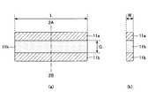
- FIG. 2A is a side view of the electrodes 11a and 11b provided in the laser chamber 10
- FIG. 2B is a cross-sectional view taken along the alternate long and short dash line 2A-2B in FIG. 2A.
- the pair of electrodes 11a and 11b arranged in the laser chamber 10 may be arranged at a predetermined position so that a predetermined discharge region 11h is formed.
- G be the gap between the electrode 11a and the electrode 11b.
- the equation for obtaining the area S of the discharge surface of the electrodes 11a and 11b is S ⁇ W ⁇ L.
- the area S of the discharge surface may be calculated based on the portion that actually discharges on the surfaces of the electrodes 11a and 11b.
- the area S of the discharge surface may be a measured area of the used electrode and may be used as the area S of the discharge surface.
- the area S of the discharge surface can be calculated by setting L as the length of the shorter electrode and W as the width of the narrower electrode. Good.
- the discharge region 11h is a space between the pair of electrodes 11a and 11b, and its volume is approximated by W ⁇ L ⁇ G.
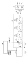
- FIG. 3 shows electric circuits such as the charger 12 and the pulse power module 13.
- the pulse power module 13 may include a semiconductor switch that is a switch 13a, magnetic switches MS 1 , MS 2 , MS 3 , a capacitor C 0 , and capacitors C 1 , C 2 , C 3 , C 4 .
- a semiconductor switch that is a switch 13a, magnetic switches MS 1 , MS 2 , MS 3 , a capacitor C 0 , and capacitors C 1 , C 2 , C 3 , C 4 .
- the switch 13a may be provided on the wire that connects the capacitor C 0 and the capacitor C 1.
- Magnetic switch MS 1 may be provided between the capacitor C 1 and capacitor C 2.
- Magnetic switch MS 2 may be provided between the capacitor C 2 and the capacitor C 3.
- Magnetic switch MS 3 may be provided between the capacitor C 3 and the capacitor C 4.
- Voltage measuring device 41 may measure the voltage applied to the capacitor C 0.
- the voltage measuring device 51 and connected to the electrode 11a and the electrode 11b, may be circuitry on the current measuring device 52 is provided as needed between the one electrode and the electrode 11a of the capacitor C 4.
- the current measuring device 52 may be a current probe, for example.
- the voltage measuring device 51 may measure the voltage between the electrode 11a and the electrode 11b.
- the current measuring device 52 may measure the current that flows during the discharge between the electrode 11a and the electrode 11b.
- the control unit 30 sets a command value for the voltage Vhv for charging the capacitor C 0 in the charger 12. Charger based on this command value 12 may be charged to charge the capacitor C 0, as the voltage applied to the capacitor C 0 is Vhv.
- control unit 30 the signal to the switch 13a is transmitted, the switch 13a is closed, a current I1 flows from the capacitor C 0 to the capacitor C 1, the capacitor C 1 may be charged.
- the current I3 flows from the capacitor C 2 to the capacitor C 3, the charge in the capacitor C 3 may be charged. At this time, the charge in the capacitor C 3 is shorter than the pulse width of the pulse width of the current I3 I2 may be charged.
- the current flows sequentially from the capacitor C 1 to the capacitor C 2 , from the capacitor C 2 to the capacitor C 3 , and from the capacitor C 3 to the capacitor C 4 , so that the pulse width is shortened and the capacitor C 4 is charged. May be.
- the voltage between the electrodes 11a and the electrodes 11b provided in the laser chamber 10 is applied from the capacitor C 4, a discharge may occur in the laser gas between the electrodes 11a and the electrodes 11b.
- the consumption rate coefficient ⁇ for each electrode material will be described.
- the amount of consumption of the electrodes 11a and 11b depends on the material forming the electrodes 11a and 11b. For this reason, the consumption rate coefficient ⁇ of the material forming the electrodes 11a and 11b may be measured in advance and used when predicting the lifetime of the electrodes 11a and 11b.
- FIG. 4 shows the results of measurement by the inventor on the relationship between the electrode consumption amount Rd in the electrodes 11a and 11b and the integrated value Einsum of the input energy to the electrodes 11a and 11b. Show. From the results shown in FIG. 4, the electrode consumption amount Rd in the electrodes 11a and 11b and the integrated value Einsum of the input energy to the electrodes 11a and 11b are in a substantially proportional relationship.
- a desired laser performance for example, desired output pulse energy
- the electrodes 11a and 11b can be predicted to have reached the life of the electrodes. it can. That is, in this case, 190 ⁇ 10 9 J is the accumulated life value Einsumlife of the input energy that becomes the electrode life.
- the electrode life of the electrodes 11a and 11b can be determined based on the integrated value of the energy input to the electrodes 11a and 11b.
- the energy Ein i input to the electrodes 11a and 11b by the i-th pulse laser oscillation is calculated from the charging voltage VHv i and the capacitance C 0C of the capacitor C 0 provided in the pulse power module 13 according to the above equation (1). It can be calculated from the equation shown in (2).
- Ein i k ⁇ C 0C ⁇ (Vhv i) 2/2 ⁇ (2)
- the consumption rate coefficient ⁇ of the electrodes 11a and 11b can be obtained from the gradient of the electrode consumption amount Rd with respect to the integrated value Einsum of the input energy based on the graph as shown in FIG.
- the electrode consumption amount Rd may be calculated by the following equation (4).
- the lifetimes of the electrodes 11a and 11b can be predicted based on the integrated value Einsum of the energy input to the electrodes 11a and 11b.
- the accumulated life value Einsumlife of the input energy can be calculated from the electrode consumption amount Rdlife, the area S of the discharge surface of the electrodes 11a and 11b, and the consumption rate coefficient ⁇ of the electrodes 11a and 11b. it can.
- Whether or not the electrodes 11a and 11b have reached the end of life may be determined to have reached the end of life when the relationship of the following equation (6) is satisfied.
- the control unit 30 notifies an external device (not shown) that the electrodes have reached the end of life, or an operation panel (not shown) of the laser device, etc. It may be displayed.
- the control unit 30 notifies the external device not shown that the electrode life is near or displays it on the operation panel not shown of the laser device. May be.
- ⁇ may be a value in the range of 0.8 ⁇ ⁇ ⁇ 1.
- the charging voltage Vhv i has been described using the value set in the charger 12.
- the integrated value Einsum of the input energy may be calculated based on the voltage value of the capacitor C 0 measured by the voltage measuring device 41 shown in FIG.
- the integrated value Einsum of the input energy may be calculated based on the voltage value and the current value applied to the electrodes 11a and 11b measured by the voltage measuring device 51 and the current measuring device 52 shown in FIG.
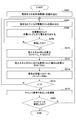
- Electrode lifetime prediction method 1 Based on FIG. 5, the control method of a laser apparatus, especially the electrode lifetime prediction method will be described.
- the control unit 30 may read the integrated value of energy already input to the electrodes 11a and 11b, and set the read integrated value of input energy as Einsum.
- the integrated value of energy already input to the electrodes 11a and 11b may be an integrated value of energy input to the electrodes 11a and 11b until the laser chamber 10 is installed in the laser apparatus. Specifically, the case where the discharge between the electrodes 11a and 11b has already been performed in another laser device can be mentioned. Further, when the electrodes 11a and 11b are not yet discharged, the integrated value Einsum of input energy may be set to zero.
- control unit 30 may read the charging voltage Vhv set in the charger 12 in step S104.
- control unit 30, in step S106, the battery charger 12 may apply a voltage Vhv to capacitor C 0.
- step S108 the control unit 30 may determine whether or not a discharge has occurred between the electrode 11a and the electrode 11b in the laser chamber 10. If it is determined that the battery has been discharged, the process may proceed to step S110. On the other hand, if it is determined that the battery is not discharged, the process may move to step S104.
- the determination as to whether or not the discharge has occurred may be as described below, for example. The determination may be made based on whether or not a trigger signal is transmitted to the switch 13a. The determination may be made based on whether or not the laser beam is detected by the energy monitor unit 17.
- control unit 30 may add the input energy Ein calculated in step S110 to the current input energy integrated value Einsum to obtain a new input energy integrated value Einsum.
- step S114 the control unit 30 may determine whether or not the integrated value Einsum of the input energy exceeds the integrated life value Einsumlife of the input energy. If it is determined that the integrated value Einsum of the input energy exceeds the integrated life value Einsumlife of the input energy, the process may proceed to step S116. On the other hand, when it is determined that the integrated value Einsum of the input energy does not exceed the integrated life value Einsumlife of the input energy, the process may proceed to step S104.
- step S116 since the electrodes 11a and 11b have reached the end of their lives, it may be notified to an external device not shown that the laser chamber 10 has the end of life. Further, it may be displayed on an operation panel or the like (not shown) of the laser device instead of reporting to the external device.
- the control unit 30 may determine whether or not maintenance such as chamber replacement has been performed in step S118. If it is determined that maintenance has been performed, the flow of the electrode life prediction method may be terminated. On the other hand, if it is determined that maintenance is not performed, the process may move to step S104.
- the maintenance is chamber replacement, the serial number of the laser chamber 10 may be recognized, and it may be determined whether the chamber replacement has been performed based on whether the serial number is different.
- the installation positions of the electrodes 11a and 11b may be recognized, and the determination may be made based on whether or not the installation positions of the electrodes 11a and 11b have changed.
- the serial numbers of the electrodes 11a and 11b are recognized, and whether or not the electrodes 11a and 11b have been replaced depends on whether the serial numbers are different. You may judge.
- the calculation of the input energy Ein may be performed based on the voltage value of the capacitor C 0 measured by the voltage measuring device 41. In this case, the measurement of the voltage of the capacitor C 0 by the voltage measuring device 41 may be performed in the process of step S108 and the like. Alternatively, the input energy Ein may be calculated by substituting Vhv for a value obtained by multiplying the voltage measured by the voltage measuring device 41 by a predetermined coefficient as necessary.
- the input energy Ein may be calculated based on the voltage and current measured by the voltage measuring device 51 and the current measuring device 52.
- the measurement of the voltage and current in the voltage measuring device 51 and the current measuring device 52 may be performed together in the process of step S108 and the like.
- the input energy Ein may be calculated by multiplying the product of the voltage measured by the voltage measuring device 51 and the current measured by the current measuring device 52 by a predetermined coefficient as necessary.
- Electrode lifetime prediction method 2 Next, another method for predicting the electrode life will be described with reference to FIG. 6 may be determined based on the relationship between the input energy Ein and the number of shots Blife that is the life.
- the relationship between the input energy Ein shown in FIG. 6 and the number of shots Blife at which the electrode reaches the end of its life may be measured in advance by a test.
- the control unit 30 When the life index value Lf is 1 ⁇ Lf, the control unit 30 notifies an external device (not shown) that the electrode has reached the end of life, or an operation panel (not shown) of the laser device. It may be displayed. When the life index value Lf is in the range of 0.8 ⁇ Lf ⁇ 1, the control unit 30 notifies the external device (not shown) that the life of the electrode is near, or the laser device May be displayed on an operation panel (not shown).
- the control unit 30 may read the current life index value Lf in step S202.
- control unit 30 may read the charging voltage Vhv set in the charger 12 in step S204.
- step S206 the control unit 30 in step S206, the battery charger 12, so that the charging voltage Vhv, a voltage may be applied to the capacitor C 0.
- step S208 the control unit 30 may determine whether or not a discharge has occurred between the electrode 11a and the electrode 11b in the laser chamber 10. If it is determined that the battery has been discharged, the process may proceed to step S210. On the other hand, when it is determined that the battery is not discharged, the process may move to step S204.
- the determination of whether or not the discharge has occurred may be described as follows, for example. The determination may be made based on whether or not a trigger signal is transmitted to the switch 13a. Further, the determination may be made based on whether or not the laser light is detected in the energy monitor unit 17.
- control unit 30 may calculate the input energy Ein in step S210.
- the input energy Ein may be calculated based on the equation (1).
- control unit 30 may add a reciprocal of the life shot number Blife calculated in step S212 to the current life index value Lf to obtain a new life index value Lf.
- control unit 30 may determine whether or not the life index value Lf exceeds 1 in step S216. When it is determined that the life index value Lf exceeds 1, the process may move to step S218. On the other hand, when it is determined that the life index value Lf does not exceed 1, the process may proceed to step S204.
- control unit 30 may notify an external device (not shown) that the laser chamber 10 has reached the end of its life because the electrodes 11a and 11b have reached the end of their end. Instead of reporting to the external device, it may be displayed on an operation panel (not shown) of the laser device.
- step S220 it may be determined whether or not maintenance such as chamber replacement has been performed. If it is determined that maintenance has been performed, the flow of the electrode life prediction method may be terminated. On the other hand, if it is determined that maintenance is not performed, the process may move to step S204.
- the maintenance is chamber replacement, the serial number in the laser chamber 10 may be recognized, and it may be determined whether the chamber replacement has been performed based on whether the serial number is different.
- the installation positions of the electrodes 11a and 11b may be recognized, and the determination may be made based on whether or not the installation positions of the electrodes 11a and 11b have changed.
- the serial numbers of the electrodes 11a and 11b are recognized, and whether or not the electrodes 11a and 11b have been replaced depends on whether the serial numbers are different. You may judge.
- the calculation of the input energy Ein may be performed based on the voltage value of the capacitor C 0 measured by the voltage measuring device 41. In this case, measurement of the voltage of the capacitor C 0 by a voltage measuring device 41 may be performed during the process step, such as step S208. Alternatively, the input energy Ein may be calculated by substituting Vhv for a value obtained by multiplying the voltage measured by the voltage measuring device 41 by a predetermined coefficient as necessary.
- the input energy Ein may be calculated based on the voltage and current measured by the voltage measuring device 51 and the current measuring device 52.
- the measurement of the voltage and current in the voltage measuring device 51 and the current measuring device 52 may be performed together in the process of step S208 or the like.
- the input energy Ein may be calculated by multiplying the product of the voltage measured by the voltage measuring device 51 and the current measured by the current measuring device 52 by a predetermined coefficient as necessary.
- Electrode life prediction method 3 Based on FIG. 8, another method for predicting the electrode life will be described.
- the control unit 30 may read an integrated value of energy already input to the electrodes 11a and 11b and calculate an input energy life index value EinL. Specifically, the control unit 30 reads the integrated value of the energy already input to the electrodes 11a and 11b, and subtracts the input integrated value of the input energy from the integrated life value Einsumlife of the input energy, thereby calculating the input energy life index. The value EinL may be calculated. Further, the integrated value of the input energy input to the electrodes 11a and 11b so far may be the integrated value of the input energy input to the electrodes 11a and 11b until the laser chamber 10 is installed in the laser apparatus. Good. Specifically, the case where the discharge between the electrodes 11a and 11b is already performed in another laser device can be mentioned. Further, when the electrodes 11a and 11b are not yet discharged, the integrated value of the input energy may be zero. In this case, the input energy life index value EinL is equal to the integrated life value Einsumlife of the input energy.
- control unit 30 may read the charging voltage Vhv set in the charger 12 in step S304.
- control unit 30, in step S306, the battery charger 12 may apply a voltage Vhv to capacitor C 0.
- step S308 the control unit 30 may determine whether or not a discharge has occurred between the electrode 11a and the electrode 11b in the laser chamber 10. If it is determined that the battery has been discharged, the process may proceed to step S310. On the other hand, if it is determined that the battery is not discharged, the process may move to step S304.
- the determination of whether or not the discharge has occurred may be described as follows, for example. The determination may be made based on whether or not a trigger signal is transmitted to the switch 13a. Further, the determination may be made based on whether or not the laser light is detected in the energy monitor unit 17.
- control unit 30 may calculate the input energy Ein in step S310.
- the input energy Ein may be calculated based on the equation (1).
- control unit 30 may set the new input energy life index value EinL by subtracting the input energy Ein calculated in step S310 from the current input energy life index value EinL.
- control unit 30 may determine whether or not the input energy life index value EinL is smaller than 0 in step S314. When it is determined that the input energy life index value EinL is smaller than 0, the process may proceed to step S316. On the other hand, when it is determined that the input energy life index value EinL is not smaller than 0, the process may proceed to step S304.
- control unit 30 may notify an external device (not shown) that the laser chamber 10 has reached the end of its life because the electrodes 11a and 11b have reached the end of their end. Instead of reporting to the external device, the fact that the laser chamber 10 has reached the end of its life may be displayed on an operation panel (not shown) of the laser device.
- step S3108 the control unit 30 may determine whether maintenance such as chamber replacement has been performed. If it is determined that maintenance has been performed, the flow of the electrode life prediction method may be terminated. On the other hand, if it is determined that maintenance is not performed, the process may move to step S304.
- the maintenance is chamber replacement, the serial number in the laser chamber 10 may be recognized, and it may be determined whether the chamber replacement has been performed based on whether the serial number is different. Further, when the maintenance is adjustment of the gap G in the electrodes 11a and 11b, the position in the electrodes 11a and 11b may be recognized and the determination may be made based on whether or not the position in the electrodes 11a and 11b has changed.
- the serial numbers of the electrodes 11a and 11b are recognized, and whether or not the electrodes 11a and 11b have been replaced depends on whether the serial numbers are different. You may judge.
- the calculation of the input energy Ein may be performed based on the voltage value of the capacitor C 0 measured by the voltage measuring device 41. In this case, measurement of the voltage of the capacitor C 0 by a voltage measuring device 41 may be performed during the process step, such as step S308. Alternatively, the input energy Ein may be calculated by substituting Vhv for a value obtained by multiplying the voltage measured by the voltage measuring device 41 by a predetermined coefficient as necessary.
- the input energy Ein may be calculated based on the voltage and current measured by the voltage measuring device 51 and the current measuring device 52.
- the measurement of the voltage and current in the voltage measuring device 51 and the current measuring device 52 may be performed together in the process of step S308 and the like.
- the input energy Ein may be calculated by multiplying the product of the voltage measured by the voltage measuring device 51 and the current measured by the current measuring device 52 by a predetermined coefficient as necessary.
- the pulse energy E of the pulse laser beam may be monitored, and the integrated value Einsum of the input energy may be approximated from the value of the input energy Ein corresponding to the value of the pulse energy E.
- the value of the input energy Ein when the pulse energy E in the pulse laser beam is less than 10 mJ, the value of the input energy Ein may be Eina (J). Further, when the pulse energy E in the pulse laser beam is 10 mJ or more and less than 11.25 mJ, the value of the input energy Ein may be Einb (J). Further, when the pulse energy E in the pulse laser beam is 11.25 mJ or more and less than 13.75 mJ, the value of the input energy Ein may be Einc (J). Further, when the pulse energy E in the pulse laser beam is 13.75 mJ or more and less than 15 mJ, the value of the input energy Ein may be Eind (J). Moreover, when the pulse energy E in the pulse laser beam is 15 mJ or more, the value of the input energy Ein may be Amsterdam (J).
- na is the shot number nb of the pulse laser light having a pulse energy E of less than 10 mJ
- the shot number nc of the pulse laser light having a pulse energy E of 10 mJ or more and less than 11.25 mJ is 11 in the pulse energy E.
- a pulse laser beam shot number nd of .25 mJ or more and less than 13.75 mJ has a pulse energy E of 13.75 mJ or more and a pulse laser beam shot number ne of less than 15 mJ has a pulse energy E of 15 mJ or more.
- the control unit 30 may read the integrated value of energy already input to the electrodes 11a and 11b, and set the read integrated value of input energy as Einsum.
- the integrated value of energy already input to the electrodes 11a and 11b may be an integrated value of energy input to the electrodes 11a and 11b until the laser chamber 10 is installed in the laser apparatus. Specifically, the case where the laser chamber 10 has already been discharged between the electrodes 11a and 11b in another laser device can be cited. Further, when the electrodes 11a and 11b are not yet discharged, the integrated value Einsum of input energy may be set to zero.
- control unit 30 may determine whether or not laser oscillation has occurred in step S334. Specifically, whether or not laser oscillation has occurred may be determined based on whether or not the pulse laser beam is detected in the optical sensor 17c in the energy monitor unit 17. If it is determined that laser oscillation has occurred, the process may proceed to step S336. On the other hand, when it is determined that laser oscillation is not occurring, step S334 may be repeated.
- the optical sensor 17c in the energy monitor unit 17 may measure the pulse energy E of the pulse laser beam in step S336.
- step S338 the control unit 30 may perform a subroutine for specifying a range of pulse energy described later. Thereby, the corresponding input energy Ein may be obtained from the pulse energy E of the pulse laser beam measured in step S336.
- step S340 the control unit 30 may add the input energy Ein obtained in step S338 to the current input energy integrated value Einsum to obtain a new input energy integrated value Einsum.
- step S342 the control unit 30 may determine whether or not the integrated value Einsum of the input energy exceeds the integrated lifetime value Einsumlife of the input energy. If it is determined that the integrated value Einsum of the input energy exceeds the integrated life value Einsumlife of the input energy, the process may proceed to step S344. On the other hand, when it is determined that the integrated value Einsum of the input energy does not exceed the integrated life value Einsumlife of the input energy, the process may proceed to step S334.
- step S344 since the electrodes 11a and 11b have reached the end of their lives, it may be notified to an external device not shown that the laser chamber 10 has the end of life. Further, it may be displayed on an operation panel or the like (not shown) of the laser device instead of reporting to the external device.
- step S346 the control unit 30 may determine whether or not maintenance such as chamber replacement has been performed. If it is determined that maintenance has been performed, the flow of the electrode life prediction method may be terminated. On the other hand, if it is determined that maintenance is not performed, the process may move to step S334.
- the maintenance is chamber replacement, the serial number of the laser chamber 10 may be recognized, and it may be determined whether the chamber replacement has been performed based on whether the serial number is different.
- the installation positions of the electrodes 11a and 11b may be recognized, and the determination may be made based on whether or not the installation positions of the electrodes 11a and 11b have changed.
- the serial numbers of the electrodes 11a and 11b are recognized, and whether or not the electrodes 11a and 11b have been replaced depends on whether the serial numbers are different. You may judge.
- This subroutine is performed in the control unit 30 and may be a subroutine for obtaining the corresponding input energy Ein from the pulse energy E of the pulse laser beam measured in step S336.
- step S352 it may be determined whether or not the measured value of the pulse energy E of the pulse laser beam is less than 10 mJ. When the measured pulse energy E is less than 10 mJ, the process may proceed to step S354. If the measured pulse energy E is not less than 10 mJ, the process may proceed to step S356.
- step S354 the input energy Ein may be set to Eina, and thereafter, the process may return to the main routine shown in FIG.
- step S356 it may be determined whether or not the value of the measured pulse energy E of the pulse laser beam is within a range of 10 mJ or more and less than 11.25 mJ.
- the process may proceed to step S358.
- the process may move to step S360.
- step S358 the input energy Ein may be set to Einb, and thereafter, the process may return to the main routine shown in FIG.
- step S360 it may be determined whether or not the value of the measured pulse energy E of the pulsed laser light is within a range of 11.25 mJ or more and less than 13.75 mJ.
- the process may move to step S362.
- the process may move to step S364.
- step S362 the input energy Ein may be set to Einc, and thereafter, the process may return to the main routine shown in FIG.
- step S364 it may be determined whether or not the value of the measured pulse energy E of the pulse laser beam is within a range of 13.75 mJ or more and less than 15 mJ.
- the process may proceed to step S366.
- the process may proceed to step S368.
- step S366 the input energy Ein may be set to Eind, and thereafter, the process may return to the main routine shown in FIG.
- step S368 the input energy Ein may be set to Amsterdam, and thereafter, the process may return to the main routine shown in FIG.
- the double chamber excimer laser device may include an MO 200, a PO 300, a control unit 230, and high reflection mirrors 261 and 262.
- MO and PO are abbreviations for master oscillator and power oscillator, respectively.
- MO 200 may have the same structure as the laser device shown in FIG. Specifically, the MO 200 may include an MO laser chamber 210, an MO charger 212, an MO pulse power module 213, a laser resonator, and an MO energy monitor unit 217.
- the MO laser chamber 210 may include a pair of electrodes 211a and 211b and two windows 210a and 210b through which laser light is transmitted.
- the laser resonator may include a band narrowing module 214 and an MO output coupling mirror 215.
- the MO laser chamber 210 may be disposed on the optical path of the laser resonator.
- the narrowband module 214 may include a prism 214a and a grating 214b.
- the prism 214a may enlarge the beam width.
- the grating 214b may be Littrow arranged so that the laser device oscillates at the target wavelength.
- the MO output coupling mirror 215 may be a partial reflection mirror that reflects part of the laser light and transmits part of the laser light.
- the MO energy monitor unit 217 may include a beam splitter 217a, a condensing lens 217b, and an optical sensor 217c that are disposed on the optical path of the laser light that has passed through the MO output coupling mirror 215.
- the MO pulse power module 213 includes a capacitor not shown in FIG. 12, is connected to the electrodes 211a and 211b, and may further include a switch 213a. A discharge may be generated between the electrodes 211a and 211b by inputting a trigger signal to the switch 213a.
- the MO charger 212 may be connected to a capacitor provided in the MO pulse power module 213.
- PO 300 may include a PO laser chamber 310, a PO charger 312, a PO pulse power module 313, a laser resonator, and a PO energy monitor unit 317.
- the PO laser chamber 310 may include a pair of electrodes 311a and 311b and two windows 310a and 310b through which laser light is transmitted.
- the laser resonator may include a partial reflection mirror 318 and a PO output coupling mirror 315.
- the PO laser chamber 310 may be disposed on the optical path of the laser resonator.
- the PO output coupling mirror 315 may be a partial reflection mirror that reflects part of the laser light and transmits part of the laser light.
- the PO energy monitor unit 317 may include a beam splitter 317a, a condensing lens 317b, and an optical sensor 317c arranged on the optical path of the laser light that has passed through the PO output coupling mirror 315.
- the PO pulse power module 313 includes a capacitor not shown in FIG. 12, is connected to the electrodes 311a and 311b, and may further include a switch 313a. A discharge may occur between the electrodes 311a and 311b by inputting a trigger signal to the switch 313a.
- the PO charger 312 may be connected to a capacitor provided in the PO pulse power module 313.
- the control unit 230 may receive the target pulse energy Et and the oscillation trigger signal transmitted from the exposure apparatus controller 110 provided in the exposure apparatus 100.
- the control unit 230 Based on the received target pulse energy Et and the oscillation trigger signal, the control unit 230 applies a predetermined charging voltage to the MO charger 212 so that the pulse energy of the laser beam output from the PO 300 becomes the target pulse energy Et. (Vhvmo) may be set, and a predetermined charging voltage (Vhvpo) may be set for the PO charger 312 as well.
- the control unit 230 may apply a voltage between the electrode 211a and the electrode 211b by operating the switch 213a provided in the MO pulse power module 213 after a predetermined time from the oscillation trigger input.
- a voltage may be applied between the electrode 311a and the electrode 311b by operating the switch 313a provided in the PO pulse power module 313 after another predetermined time predetermined from the operation of the switch 213a.
- the laser gas When a discharge occurs between the electrodes 211a and 211b of the MO laser chamber 210, the laser gas is excited, and light can be generated from the excited laser gas.
- the light can resonate between the MO output coupling mirror 215 and the band narrowing module 214, and can oscillate.
- a part of the laser beam narrowed by the prism 214a and the grating 214b may be transmitted through the MO output coupling mirror 215 and output.
- a part of the output laser light is reflected by the beam splitter 217 a, the pulse energy Emo is detected by the MO energy monitor unit 217, and the value of the detected pulse energy Emo may be transmitted to the control unit 230.
- the laser light (seed light) output from the MO 200 and transmitted through the beam splitter 217a may be reflected by the high reflection mirrors 261 and 262 and enter the partial reflection mirror 318 provided in the PO 300.
- a part of the incident laser beam may be transmitted and may be incident on the space between the electrodes 311a and 311b of the PO laser chamber 310.
- the laser light output from the MO 200 is discharged between the electrodes 310a and 310b in the PO laser chamber 310 at a timing at which the laser light is present in the space between the electrodes 311a and 311b of the PO laser chamber 310 via the partial reflection mirror 318.
- the laser gas may be excited.
- the laser light incident on the PO 300 may be amplified and transmitted through the PO output coupling mirror 315 to output the laser light.
- a part of the laser beam transmitted through the PO output coupling mirror 315 is reflected by the beam splitter 317a, and its pulse energy Epo is detected by the PO energy monitor unit 317.
- the value of the detected pulse energy Epo is determined by the control unit. 230 may be transmitted.
- the charging voltage may be feedback-controlled so that the next output light energy of the MO 200 approaches a predetermined pulse energy Emot based on the value of the pulse energy Emo.
- the charging voltage may be feedback-controlled so that the next output light energy of PO300 approaches the target pulse energy Et based on the value of the pulse energy Epo.
- the control unit 230 may determine the electrode lifetime of the electrodes 211a and 211b in the MO laser chamber 210 in the MO 200 based on the charging voltage Vhvmo and the pulse energy Emo.
- the control unit 230 may predict the electrode lifetimes of the electrodes 311a and 311b in the PO laser chamber 310 in the PO 300 based on the charging voltage Vhvpo and the pulse energy Epo. Details of the prediction method will be described later.
- the electrode life of the electrode is predicted based on the charging voltage Vhvmo, the pulse energy Emo, the charging voltage Vhvpo, and the pulse energy Epo. Also good. Details of the prediction method will be described later.
- the control unit 230 may read an integrated value of input energy that has been input to the electrodes 211a and 211b up to the present, and may use the read integrated value of input energy as an integrated value Einsummo of input energy.
- control unit 230 may read the charging voltage Vhvmo set in the MO charger 212 in step S404.
- the controller 230 may apply the voltage Vhvmo to the capacitor Cmo 0 by the MO charger 212 in step S406.
- the capacity of the capacitor is Cmo 0C .
- step S408 the control unit 230 may determine whether or not a discharge has occurred between the electrode 211a and the electrode 211b in the MO laser chamber 210. If it is determined that the battery has been discharged, the process may proceed to step S410. On the other hand, if it is determined that the battery is not discharged, the process may move to step S404.
- the determination of whether or not the discharge has occurred may be described as follows, for example. The determination may be made based on whether a trigger signal is transmitted to the switch 213a. The determination may be made based on whether or not the laser light is detected by the MO energy monitor unit 217.
- step S412 the input energy Einsum calculated in step S410 may be added to the current input energy integrated value Einsummo to obtain a new input energy integrated value Einsummo.
- step S414 it may be determined whether the integrated value Einsummo of the input energy exceeds the integrated lifetime value Einsumlifemo of the input energy of the MO 200. If it is determined that the integrated value Einsummo of the input energy exceeds the integrated lifetime value Einsumlifemo of the input energy, the process may proceed to step S416. On the other hand, when it is determined that the integrated value Einsummo of the input energy does not exceed the integrated life value Einsumlifemo of the input energy, the process may proceed to step S404.
- step S416 since the electrodes 211a and 211b have reached the end of their lives, a notification that the MO laser chamber 210 has reached the end of life may be sent to an external device not shown.
- a request to move the one used as the MO laser chamber 210 to be used as the PO laser chamber 310 may be notified to the external device or the like. Thereafter, the chamber used as the MO laser chamber 210 may be moved to the position of the PO laser chamber 310.
- step S4108 since the one used as the MO laser chamber 210 is used as the PO laser chamber 310, it may be determined whether or not the chamber has been moved. If it is determined that the chamber has been moved, the process proceeds to step S422. On the other hand, if it is determined that the chamber is not moved, the process proceeds to step S404.
- the integrated value Einsummo of the input energy up to the present may be set as the integrated value Einsumpo of the input energy.
- the MO laser chamber 210 and the PO laser chamber 310 are moved.
- the reference numerals and the like in these are assumed to be different.
- step S424 the charging voltage Vhvpo set in the PO charger 312 may be read.
- the PO charger 312 may apply a voltage Vhvpo the capacitor Cpo 0.
- the capacity of the capacitor is Cpo 0C .
- step S428 it may be determined whether or not a discharge has occurred between the electrode 311a and the electrode 311b in the PO laser chamber 310. If it is determined that the battery has been discharged, the process may proceed to step S430. On the other hand, if it is determined that the battery is not discharged, the process may move to step S424.
- the determination as to whether or not the discharge has occurred may be as described below, for example. The determination may be made based on whether or not a trigger signal is transmitted to the switch 313a. The determination may be made based on whether the laser light is detected by the PO energy monitor unit 317 or not.
- step S432 the input energy Einpo calculated in step S430 may be added to the current input energy integrated value Einsumpo to obtain a new input energy integrated value Einsumpo.
- step S434 it may be determined whether the integrated value Einsumpo of the input energy exceeds the integrated life value Einsumlifepo of the input energy. If it is determined that the integrated value Einsumpo of the input energy exceeds the integrated life value Einsumlifepo of the input energy, the process may proceed to step S436. On the other hand, when it is determined that the integrated value Einsumpo of the input energy does not exceed the integrated life value Einsumlifepo of the input energy, the process may proceed to step S424.
- step S436 it may be notified to an external device (not shown) that the PO laser chamber 310 has a lifetime because the electrodes 311a and 311b have reached the lifetime. Instead of reporting to the external device, it may be displayed on an operation panel (not shown) of the laser device.
- step S4308 it may be determined whether or not maintenance such as chamber replacement has been performed. If it is determined that maintenance has been performed, the flow of the electrode life prediction method may be terminated. On the other hand, if it is determined that maintenance is not performed, the process may proceed to step S424.
- the maintenance is chamber replacement, the serial number in the PO laser chamber 310 may be recognized, and it may be determined whether the chamber replacement has been performed based on whether the serial number is different.
- the MO pulse power module 213 and the PO pulse power module 313 may be the same circuit as the circuit of FIG.
- the difference between the MO pulse power module 213, the PO pulse power module 313, and the circuit of FIG. 3 is the values of the inductance of each magnetic switch and the capacitance of each capacitor.
- the calculation of the input energy Einmo may be performed based on the voltage value of the capacitor Cmo 0 measured by a voltage measuring device (not shown). In this case, the measurement of the voltage of the capacitor Cmo 0 by the voltage measuring device may be performed in the process of step S408 and the like. Alternatively, the input energy Einmo may be calculated by substituting a value obtained by multiplying the voltage measured by the voltage measuring instrument by a predetermined coefficient as necessary with Vhvmo.
- the calculation of the input energy Einpo may be performed based on the voltage value of the capacitor Cpo 0 measured by a voltage measuring device (not shown). In this case, the measurement of the voltage of the capacitor Cpo 0 by the voltage measuring device may be performed in the process of step S428. Alternatively, the input energy Einpo may be calculated by substituting a value obtained by multiplying the voltage measured by the voltage measuring instrument by a predetermined coefficient as necessary with Vhvpo.
- the input energy Einmo is calculated based on the voltage value between the electrodes 211a and 211b measured by a voltage measuring device (not shown) and the current value flowing during discharge measured by a current measuring device (not shown). May be. In this case, the voltage and current measurement by the voltage measuring device and the current measuring device may be performed together in the process of step S408 and the like. Further, the input energy Einmo may be calculated by multiplying the product of the voltage measured by the voltage measuring instrument and the current measured by the current measuring instrument by a predetermined coefficient as necessary.
- the input energy Einpo is calculated based on the voltage value between the electrodes 311a and 311b measured by a voltage measuring device (not shown) and the current value flowing during discharge measured by a current measuring device (not shown). May be.
- the measurement of the voltage and current in the voltage measuring device and the current measuring device may be performed together in the process of step S428 and the like.
- the input energy Einpo may be calculated by multiplying the product of the voltage measured by the voltage measuring instrument and the current measured by the current measuring instrument by a predetermined coefficient as necessary.
- step S416 the life of the electrode is regarded as the life of the chamber, and the chamber used as the MO laser chamber 210 is moved as the PO laser chamber 310.
- it may be handled by replacing the electrode instead of moving the chamber, and if desired laser characteristics can be obtained by adjusting the electrode gap, it can be handled by adjusting the electrode gap. May be.
- the MO laser chamber 210 is used as the PO laser chamber 310 .
- the MO laser chamber 210 is moved. May be.
Landscapes
- Physics & Mathematics (AREA)
- Electromagnetism (AREA)
- Engineering & Computer Science (AREA)
- Plasma & Fusion (AREA)
- Optics & Photonics (AREA)
- Microelectronics & Electronic Packaging (AREA)
- Lasers (AREA)
Priority Applications (2)
| Application Number | Priority Date | Filing Date | Title |
|---|---|---|---|
| JP2014526983A JP6165142B2 (ja) | 2012-07-26 | 2013-07-24 | レーザ装置及びレーザ装置の制御方法 |
| US14/602,208 US9647415B2 (en) | 2012-07-26 | 2015-01-21 | Laser apparatus and method of controlling laser apparatus |
Applications Claiming Priority (2)
| Application Number | Priority Date | Filing Date | Title |
|---|---|---|---|
| JP2012166292 | 2012-07-26 | ||
| JP2012-166292 | 2012-07-26 |
Related Child Applications (1)
| Application Number | Title | Priority Date | Filing Date |
|---|---|---|---|
| US14/602,208 Continuation US9647415B2 (en) | 2012-07-26 | 2015-01-21 | Laser apparatus and method of controlling laser apparatus |
Publications (1)
| Publication Number | Publication Date |
|---|---|
| WO2014017562A1 true WO2014017562A1 (fr) | 2014-01-30 |
Family
ID=49997371
Family Applications (1)
| Application Number | Title | Priority Date | Filing Date |
|---|---|---|---|
| PCT/JP2013/070110 Ceased WO2014017562A1 (fr) | 2012-07-26 | 2013-07-24 | Dispositif laser et procédé de commande de dispositif laser |
Country Status (3)
| Country | Link |
|---|---|
| US (1) | US9647415B2 (fr) |
| JP (1) | JP6165142B2 (fr) |
| WO (1) | WO2014017562A1 (fr) |
Cited By (4)
| Publication number | Priority date | Publication date | Assignee | Title |
|---|---|---|---|---|
| WO2015140930A1 (fr) * | 2014-03-18 | 2015-09-24 | ギガフォトン株式会社 | Dispositif de laser à gaz et procédé de commande associé |
| WO2020161865A1 (fr) * | 2019-02-07 | 2020-08-13 | ギガフォトン株式会社 | Procédé d'apprentissage automatique, dispositif de gestion d'article consommable et support lisible par ordinateur |
| WO2022018795A1 (fr) * | 2020-07-20 | 2022-01-27 | ギガフォトン株式会社 | Procédé de création de données d'entraînement, procédé d'apprentissage automatique, dispositif de gestion d'article consommable et support lisible par ordinateur |
| US11841267B2 (en) | 2018-07-05 | 2023-12-12 | Gigaphoton Inc. | Energy measuring apparatus and excimer laser apparatus |
Families Citing this family (1)
| Publication number | Priority date | Publication date | Assignee | Title |
|---|---|---|---|---|
| JP6845255B2 (ja) * | 2016-12-05 | 2021-03-17 | ギガフォトン株式会社 | レーザ装置 |
Citations (8)
| Publication number | Priority date | Publication date | Assignee | Title |
|---|---|---|---|---|
| JPH05291649A (ja) * | 1992-04-13 | 1993-11-05 | Fanuc Ltd | レーザ発振器の制御装置 |
| JPH09223833A (ja) * | 1996-02-12 | 1997-08-26 | Cymer Inc | 部品の耐用期間の終焉を予測可能なレーザーシステム及びその予測方法 |
| JPH10135542A (ja) * | 1996-10-29 | 1998-05-22 | Fanuc Ltd | ガス放電励起レーザ装置 |
| JPH11177166A (ja) * | 1997-12-11 | 1999-07-02 | Amada Eng Center Co Ltd | Yagレーザの電源装置 |
| JP2002043219A (ja) * | 2000-04-25 | 2002-02-08 | Gigaphoton Inc | レーザ装置管理システム |
| JP2003243753A (ja) * | 2002-02-21 | 2003-08-29 | Gigaphoton Inc | ガスレーザ装置及びガスレーザ装置のフッ素濃度制御方法 |
| JP2008225047A (ja) * | 2007-03-13 | 2008-09-25 | Seiko Epson Corp | 画像形成装置および画像形成方法 |
| JP2009018453A (ja) * | 2007-07-10 | 2009-01-29 | Seiko Epson Corp | 液体吐出装置、液体吐出装置の制御方法および液体吐出装置の制御プログラム |
Family Cites Families (13)
| Publication number | Priority date | Publication date | Assignee | Title |
|---|---|---|---|---|
| US5504766A (en) | 1992-04-13 | 1996-04-02 | Fanuc, Ltd. | Controller for laser beam oscillator |
| US5463650A (en) * | 1992-07-17 | 1995-10-31 | Kabushiki Kaisha Komatsu Seisakusho | Apparatus for controlling output of an excimer laser device |
| US5657334A (en) * | 1996-02-15 | 1997-08-12 | Cymer, Inc. | External high voltage control for a laser system |
| JPH10275951A (ja) | 1997-03-28 | 1998-10-13 | Nikon Corp | レーザ光源の寿命判定方法 |
| JP3725781B2 (ja) * | 1997-12-15 | 2005-12-14 | サイマー, インコーポレイテッド | 高パルス速度パルス電源システム |
| JP2000349017A (ja) | 1999-06-08 | 2000-12-15 | Canon Inc | 露光装置システムおよびデバイス製造方法 |
| RU2258253C2 (ru) | 2000-02-16 | 2005-08-10 | Саймер, Инк. | Система контроля технологического процесса для лазеров, используемых в литографии |
| US6810061B2 (en) * | 2001-08-27 | 2004-10-26 | Komatsu Ltd. | Discharge electrode and discharge electrode manufacturing method |
| JP3806025B2 (ja) * | 2001-11-29 | 2006-08-09 | 株式会社小松製作所 | ガスレーザ装置 |
| JP4223887B2 (ja) * | 2003-08-11 | 2009-02-12 | 株式会社小松製作所 | 2ステージレーザのパルスエネルギー制御装置及び2ステージレーザシステム |
| JP2006088163A (ja) * | 2004-09-21 | 2006-04-06 | Fanuc Ltd | レーザ装置 |
| JP5179736B2 (ja) * | 2006-09-21 | 2013-04-10 | 株式会社小松製作所 | 露光装置用レーザ装置 |
| JP6022837B2 (ja) * | 2011-10-25 | 2016-11-09 | ギガフォトン株式会社 | エキシマレーザ装置及びエキシマレーザシステム |
-
2013
- 2013-07-24 WO PCT/JP2013/070110 patent/WO2014017562A1/fr not_active Ceased
- 2013-07-24 JP JP2014526983A patent/JP6165142B2/ja active Active
-
2015
- 2015-01-21 US US14/602,208 patent/US9647415B2/en active Active
Patent Citations (8)
| Publication number | Priority date | Publication date | Assignee | Title |
|---|---|---|---|---|
| JPH05291649A (ja) * | 1992-04-13 | 1993-11-05 | Fanuc Ltd | レーザ発振器の制御装置 |
| JPH09223833A (ja) * | 1996-02-12 | 1997-08-26 | Cymer Inc | 部品の耐用期間の終焉を予測可能なレーザーシステム及びその予測方法 |
| JPH10135542A (ja) * | 1996-10-29 | 1998-05-22 | Fanuc Ltd | ガス放電励起レーザ装置 |
| JPH11177166A (ja) * | 1997-12-11 | 1999-07-02 | Amada Eng Center Co Ltd | Yagレーザの電源装置 |
| JP2002043219A (ja) * | 2000-04-25 | 2002-02-08 | Gigaphoton Inc | レーザ装置管理システム |
| JP2003243753A (ja) * | 2002-02-21 | 2003-08-29 | Gigaphoton Inc | ガスレーザ装置及びガスレーザ装置のフッ素濃度制御方法 |
| JP2008225047A (ja) * | 2007-03-13 | 2008-09-25 | Seiko Epson Corp | 画像形成装置および画像形成方法 |
| JP2009018453A (ja) * | 2007-07-10 | 2009-01-29 | Seiko Epson Corp | 液体吐出装置、液体吐出装置の制御方法および液体吐出装置の制御プログラム |
Cited By (14)
| Publication number | Priority date | Publication date | Assignee | Title |
|---|---|---|---|---|
| WO2015140930A1 (fr) * | 2014-03-18 | 2015-09-24 | ギガフォトン株式会社 | Dispositif de laser à gaz et procédé de commande associé |
| JPWO2015140930A1 (ja) * | 2014-03-18 | 2017-04-06 | ギガフォトン株式会社 | ガスレーザ装置及びその制御方法 |
| US9853410B2 (en) | 2014-03-18 | 2017-12-26 | Gigaphoton Inc. | Gas laser device and control method therefor |
| US11841267B2 (en) | 2018-07-05 | 2023-12-12 | Gigaphoton Inc. | Energy measuring apparatus and excimer laser apparatus |
| US11822324B2 (en) | 2019-02-07 | 2023-11-21 | Gigaphoton Inc. | Machine learning method, consumable management apparatus, and computer readable medium |
| JPWO2020161865A1 (ja) * | 2019-02-07 | 2021-12-09 | ギガフォトン株式会社 | 機械学習方法、消耗品管理装置、及びコンピュータ可読媒体 |
| CN113261166B (zh) * | 2019-02-07 | 2023-07-14 | 极光先进雷射株式会社 | 机器学习方法、消耗品管理装置和计算机可读介质 |
| CN113261166A (zh) * | 2019-02-07 | 2021-08-13 | 极光先进雷射株式会社 | 机器学习方法、消耗品管理装置和计算机可读介质 |
| WO2020161865A1 (fr) * | 2019-02-07 | 2020-08-13 | ギガフォトン株式会社 | Procédé d'apprentissage automatique, dispositif de gestion d'article consommable et support lisible par ordinateur |
| JP7428667B2 (ja) | 2019-02-07 | 2024-02-06 | ギガフォトン株式会社 | 機械学習方法、消耗品管理装置、及びコンピュータ可読媒体 |
| WO2022018795A1 (fr) * | 2020-07-20 | 2022-01-27 | ギガフォトン株式会社 | Procédé de création de données d'entraînement, procédé d'apprentissage automatique, dispositif de gestion d'article consommable et support lisible par ordinateur |
| JPWO2022018795A1 (fr) * | 2020-07-20 | 2022-01-27 | ||
| JP7432733B2 (ja) | 2020-07-20 | 2024-02-16 | ギガフォトン株式会社 | 訓練データ作成方法、機械学習方法、消耗品管理装置及びコンピュータ可読媒体 |
| US12579217B2 (en) | 2020-07-20 | 2026-03-17 | Gigaphoton Inc. | Training data creation method, machine learning method, consumable management device, and computer readable medium |
Also Published As
| Publication number | Publication date |
|---|---|
| US9647415B2 (en) | 2017-05-09 |
| JPWO2014017562A1 (ja) | 2016-07-11 |
| JP6165142B2 (ja) | 2017-07-19 |
| US20150139258A1 (en) | 2015-05-21 |
Similar Documents
| Publication | Publication Date | Title |
|---|---|---|
| JP6204363B2 (ja) | レーザ装置及びレーザ装置の制御方法 | |
| JP6165142B2 (ja) | レーザ装置及びレーザ装置の制御方法 | |
| JP6310390B2 (ja) | レーザ装置の制御方法及びレーザ装置 | |
| CN113261166B (zh) | 机器学习方法、消耗品管理装置和计算机可读介质 | |
| US7903700B2 (en) | Narrow-spectrum laser device | |
| US7382816B2 (en) | Two-stage laser pulse energy control device and two-stage laser system | |
| JP5114767B2 (ja) | 狭帯域化レーザのスペクトル幅調整装置 | |
| JP2000286495A (ja) | エキシマレーザーまたはフッ素分子レーザーシステム | |
| JPH08274399A (ja) | パルスレーザ装置のパルスエネルギ制御装置と方法 | |
| US10965090B2 (en) | Laser apparatus | |
| US9601893B2 (en) | Laser apparatus | |
| JP5253830B2 (ja) | レーザ装置の故障診断システム | |
| WO2018025394A1 (fr) | Dispositif laser à gaz | |
| JP5755068B2 (ja) | 狭帯域化レーザのスペクトル幅調整装置 | |
| JP5513653B2 (ja) | レーザ装置の故障診断システム | |
| JP5371208B2 (ja) | 2ステージレーザのパルスエネルギー制御装置 | |
| US20230318252A1 (en) | Control method of laser system, laser system, and electronic device manufacturing method | |
| JP2009188419A (ja) | 露光用ガスレーザ装置 | |
| JP5832581B2 (ja) | 狭帯域化レーザのスペクトル幅調整装置 | |
| US20250286339A1 (en) | Line narrowing module, laser device, and electronic device manufacturing method |
Legal Events
| Date | Code | Title | Description |
|---|---|---|---|
| 121 | Ep: the epo has been informed by wipo that ep was designated in this application |
Ref document number: 13823724 Country of ref document: EP Kind code of ref document: A1 |
|
| ENP | Entry into the national phase |
Ref document number: 2014526983 Country of ref document: JP Kind code of ref document: A |
|
| NENP | Non-entry into the national phase |
Ref country code: DE |
|
| 122 | Ep: pct application non-entry in european phase |
Ref document number: 13823724 Country of ref document: EP Kind code of ref document: A1 |