WO2014030507A1 - 耐熱性に優れた複合多孔質膜 - Google Patents
耐熱性に優れた複合多孔質膜 Download PDFInfo
- Publication number
- WO2014030507A1 WO2014030507A1 PCT/JP2013/070592 JP2013070592W WO2014030507A1 WO 2014030507 A1 WO2014030507 A1 WO 2014030507A1 JP 2013070592 W JP2013070592 W JP 2013070592W WO 2014030507 A1 WO2014030507 A1 WO 2014030507A1
- Authority
- WO
- WIPO (PCT)
- Prior art keywords
- composite porous
- heat
- inorganic filler
- porous membrane
- microporous
- Prior art date
- Legal status (The legal status is an assumption and is not a legal conclusion. Google has not performed a legal analysis and makes no representation as to the accuracy of the status listed.)
- Ceased
Links
Images

Classifications
-
- B—PERFORMING OPERATIONS; TRANSPORTING
- B32—LAYERED PRODUCTS
- B32B—LAYERED PRODUCTS, i.e. PRODUCTS BUILT-UP OF STRATA OF FLAT OR NON-FLAT, e.g. CELLULAR OR HONEYCOMB, FORM
- B32B27/00—Layered products comprising a layer of synthetic resin
- B32B27/18—Layered products comprising a layer of synthetic resin characterised by the use of special additives
- B32B27/20—Layered products comprising a layer of synthetic resin characterised by the use of special additives using fillers, pigments, thixotroping agents
-
- B—PERFORMING OPERATIONS; TRANSPORTING
- B32—LAYERED PRODUCTS
- B32B—LAYERED PRODUCTS, i.e. PRODUCTS BUILT-UP OF STRATA OF FLAT OR NON-FLAT, e.g. CELLULAR OR HONEYCOMB, FORM
- B32B27/00—Layered products comprising a layer of synthetic resin
- B32B27/06—Layered products comprising a layer of synthetic resin as the main or only constituent of a layer, which is next to another layer of the same or of a different material
- B32B27/08—Layered products comprising a layer of synthetic resin as the main or only constituent of a layer, which is next to another layer of the same or of a different material of synthetic resin
-
- B—PERFORMING OPERATIONS; TRANSPORTING
- B32—LAYERED PRODUCTS
- B32B—LAYERED PRODUCTS, i.e. PRODUCTS BUILT-UP OF STRATA OF FLAT OR NON-FLAT, e.g. CELLULAR OR HONEYCOMB, FORM
- B32B27/00—Layered products comprising a layer of synthetic resin
- B32B27/18—Layered products comprising a layer of synthetic resin characterised by the use of special additives
- B32B27/20—Layered products comprising a layer of synthetic resin characterised by the use of special additives using fillers, pigments, thixotroping agents
- B32B27/205—Layered products comprising a layer of synthetic resin characterised by the use of special additives using fillers, pigments, thixotroping agents the fillers creating voids or cavities, e.g. by stretching
-
- B—PERFORMING OPERATIONS; TRANSPORTING
- B32—LAYERED PRODUCTS
- B32B—LAYERED PRODUCTS, i.e. PRODUCTS BUILT-UP OF STRATA OF FLAT OR NON-FLAT, e.g. CELLULAR OR HONEYCOMB, FORM
- B32B27/00—Layered products comprising a layer of synthetic resin
- B32B27/32—Layered products comprising a layer of synthetic resin comprising polyolefins
-
- C—CHEMISTRY; METALLURGY
- C08—ORGANIC MACROMOLECULAR COMPOUNDS; THEIR PREPARATION OR CHEMICAL WORKING-UP; COMPOSITIONS BASED THEREON
- C08J—WORKING-UP; GENERAL PROCESSES OF COMPOUNDING; AFTER-TREATMENT NOT COVERED BY SUBCLASSES C08B, C08C, C08F, C08G or C08H
- C08J7/00—Chemical treatment or coating of shaped articles made of macromolecular substances
- C08J7/04—Coating
- C08J7/042—Coating with two or more layers, where at least one layer of a composition contains a polymer binder
-
- C—CHEMISTRY; METALLURGY
- C08—ORGANIC MACROMOLECULAR COMPOUNDS; THEIR PREPARATION OR CHEMICAL WORKING-UP; COMPOSITIONS BASED THEREON
- C08J—WORKING-UP; GENERAL PROCESSES OF COMPOUNDING; AFTER-TREATMENT NOT COVERED BY SUBCLASSES C08B, C08C, C08F, C08G or C08H
- C08J7/00—Chemical treatment or coating of shaped articles made of macromolecular substances
- C08J7/04—Coating
- C08J7/0427—Coating with only one layer of a composition containing a polymer binder
-
- C—CHEMISTRY; METALLURGY
- C08—ORGANIC MACROMOLECULAR COMPOUNDS; THEIR PREPARATION OR CHEMICAL WORKING-UP; COMPOSITIONS BASED THEREON
- C08J—WORKING-UP; GENERAL PROCESSES OF COMPOUNDING; AFTER-TREATMENT NOT COVERED BY SUBCLASSES C08B, C08C, C08F, C08G or C08H
- C08J7/00—Chemical treatment or coating of shaped articles made of macromolecular substances
- C08J7/04—Coating
- C08J7/043—Improving the adhesiveness of the coatings per se, e.g. forming primers
-
- C—CHEMISTRY; METALLURGY
- C08—ORGANIC MACROMOLECULAR COMPOUNDS; THEIR PREPARATION OR CHEMICAL WORKING-UP; COMPOSITIONS BASED THEREON
- C08J—WORKING-UP; GENERAL PROCESSES OF COMPOUNDING; AFTER-TREATMENT NOT COVERED BY SUBCLASSES C08B, C08C, C08F, C08G or C08H
- C08J9/00—Working-up of macromolecular substances to porous or cellular articles or materials; After-treatment thereof
- C08J9/36—After-treatment
-
- H—ELECTRICITY
- H01—ELECTRIC ELEMENTS
- H01M—PROCESSES OR MEANS, e.g. BATTERIES, FOR THE DIRECT CONVERSION OF CHEMICAL ENERGY INTO ELECTRICAL ENERGY
- H01M10/00—Secondary cells; Manufacture thereof
- H01M10/05—Accumulators with non-aqueous electrolyte
- H01M10/052—Li-accumulators
- H01M10/0525—Rocking-chair batteries, i.e. batteries with lithium insertion or intercalation in both electrodes; Lithium-ion batteries
-
- H—ELECTRICITY
- H01—ELECTRIC ELEMENTS
- H01M—PROCESSES OR MEANS, e.g. BATTERIES, FOR THE DIRECT CONVERSION OF CHEMICAL ENERGY INTO ELECTRICAL ENERGY
- H01M50/00—Constructional details or processes of manufacture of the non-active parts of electrochemical cells other than fuel cells, e.g. hybrid cells
- H01M50/40—Separators; Membranes; Diaphragms; Spacing elements inside cells
- H01M50/409—Separators, membranes or diaphragms characterised by the material
- H01M50/411—Organic material
- H01M50/414—Synthetic resins, e.g. thermoplastics or thermosetting resins
- H01M50/417—Polyolefins
-
- H—ELECTRICITY
- H01—ELECTRIC ELEMENTS
- H01M—PROCESSES OR MEANS, e.g. BATTERIES, FOR THE DIRECT CONVERSION OF CHEMICAL ENERGY INTO ELECTRICAL ENERGY
- H01M50/00—Constructional details or processes of manufacture of the non-active parts of electrochemical cells other than fuel cells, e.g. hybrid cells
- H01M50/40—Separators; Membranes; Diaphragms; Spacing elements inside cells
- H01M50/409—Separators, membranes or diaphragms characterised by the material
- H01M50/44—Fibrous material
-
- H—ELECTRICITY
- H01—ELECTRIC ELEMENTS
- H01M—PROCESSES OR MEANS, e.g. BATTERIES, FOR THE DIRECT CONVERSION OF CHEMICAL ENERGY INTO ELECTRICAL ENERGY
- H01M50/00—Constructional details or processes of manufacture of the non-active parts of electrochemical cells other than fuel cells, e.g. hybrid cells
- H01M50/40—Separators; Membranes; Diaphragms; Spacing elements inside cells
- H01M50/409—Separators, membranes or diaphragms characterised by the material
- H01M50/446—Composite material consisting of a mixture of organic and inorganic materials
-
- B—PERFORMING OPERATIONS; TRANSPORTING
- B32—LAYERED PRODUCTS
- B32B—LAYERED PRODUCTS, i.e. PRODUCTS BUILT-UP OF STRATA OF FLAT OR NON-FLAT, e.g. CELLULAR OR HONEYCOMB, FORM
- B32B38/00—Ancillary operations in connection with laminating processes
- B32B38/0012—Mechanical treatment, e.g. roughening, deforming, stretching
- B32B2038/0028—Stretching, elongating
-
- B—PERFORMING OPERATIONS; TRANSPORTING
- B32—LAYERED PRODUCTS
- B32B—LAYERED PRODUCTS, i.e. PRODUCTS BUILT-UP OF STRATA OF FLAT OR NON-FLAT, e.g. CELLULAR OR HONEYCOMB, FORM
- B32B2255/00—Coating on the layer surface
- B32B2255/10—Coating on the layer surface on synthetic resin layer or on natural or synthetic rubber layer
-
- B—PERFORMING OPERATIONS; TRANSPORTING
- B32—LAYERED PRODUCTS
- B32B—LAYERED PRODUCTS, i.e. PRODUCTS BUILT-UP OF STRATA OF FLAT OR NON-FLAT, e.g. CELLULAR OR HONEYCOMB, FORM
- B32B2255/00—Coating on the layer surface
- B32B2255/20—Inorganic coating
-
- B—PERFORMING OPERATIONS; TRANSPORTING
- B32—LAYERED PRODUCTS
- B32B—LAYERED PRODUCTS, i.e. PRODUCTS BUILT-UP OF STRATA OF FLAT OR NON-FLAT, e.g. CELLULAR OR HONEYCOMB, FORM
- B32B2305/00—Condition, form or state of the layers or laminate
- B32B2305/02—Cellular or porous
- B32B2305/026—Porous
-
- B—PERFORMING OPERATIONS; TRANSPORTING
- B32—LAYERED PRODUCTS
- B32B—LAYERED PRODUCTS, i.e. PRODUCTS BUILT-UP OF STRATA OF FLAT OR NON-FLAT, e.g. CELLULAR OR HONEYCOMB, FORM
- B32B2307/00—Properties of the layers or laminate
- B32B2307/50—Properties of the layers or laminate having particular mechanical properties
- B32B2307/514—Oriented
- B32B2307/516—Oriented mono-axially
-
- B—PERFORMING OPERATIONS; TRANSPORTING
- B32—LAYERED PRODUCTS
- B32B—LAYERED PRODUCTS, i.e. PRODUCTS BUILT-UP OF STRATA OF FLAT OR NON-FLAT, e.g. CELLULAR OR HONEYCOMB, FORM
- B32B2307/00—Properties of the layers or laminate
- B32B2307/50—Properties of the layers or laminate having particular mechanical properties
- B32B2307/514—Oriented
- B32B2307/518—Oriented bi-axially
-
- C—CHEMISTRY; METALLURGY
- C08—ORGANIC MACROMOLECULAR COMPOUNDS; THEIR PREPARATION OR CHEMICAL WORKING-UP; COMPOSITIONS BASED THEREON
- C08J—WORKING-UP; GENERAL PROCESSES OF COMPOUNDING; AFTER-TREATMENT NOT COVERED BY SUBCLASSES C08B, C08C, C08F, C08G or C08H
- C08J2323/00—Characterised by the use of homopolymers or copolymers of unsaturated aliphatic hydrocarbons having only one carbon-to-carbon double bond; Derivatives of such polymers
- C08J2323/02—Characterised by the use of homopolymers or copolymers of unsaturated aliphatic hydrocarbons having only one carbon-to-carbon double bond; Derivatives of such polymers not modified by chemical after treatment
- C08J2323/04—Homopolymers or copolymers of ethene
-
- C—CHEMISTRY; METALLURGY
- C08—ORGANIC MACROMOLECULAR COMPOUNDS; THEIR PREPARATION OR CHEMICAL WORKING-UP; COMPOSITIONS BASED THEREON
- C08J—WORKING-UP; GENERAL PROCESSES OF COMPOUNDING; AFTER-TREATMENT NOT COVERED BY SUBCLASSES C08B, C08C, C08F, C08G or C08H
- C08J2323/00—Characterised by the use of homopolymers or copolymers of unsaturated aliphatic hydrocarbons having only one carbon-to-carbon double bond; Derivatives of such polymers
- C08J2323/02—Characterised by the use of homopolymers or copolymers of unsaturated aliphatic hydrocarbons having only one carbon-to-carbon double bond; Derivatives of such polymers not modified by chemical after treatment
- C08J2323/10—Homopolymers or copolymers of propene
- C08J2323/12—Polypropene
-
- C—CHEMISTRY; METALLURGY
- C08—ORGANIC MACROMOLECULAR COMPOUNDS; THEIR PREPARATION OR CHEMICAL WORKING-UP; COMPOSITIONS BASED THEREON
- C08J—WORKING-UP; GENERAL PROCESSES OF COMPOUNDING; AFTER-TREATMENT NOT COVERED BY SUBCLASSES C08B, C08C, C08F, C08G or C08H
- C08J2400/00—Characterised by the use of unspecified polymers
- C08J2400/22—Thermoplastic resins
-
- C—CHEMISTRY; METALLURGY
- C08—ORGANIC MACROMOLECULAR COMPOUNDS; THEIR PREPARATION OR CHEMICAL WORKING-UP; COMPOSITIONS BASED THEREON
- C08J—WORKING-UP; GENERAL PROCESSES OF COMPOUNDING; AFTER-TREATMENT NOT COVERED BY SUBCLASSES C08B, C08C, C08F, C08G or C08H
- C08J2427/00—Characterised by the use of homopolymers or copolymers of compounds having one or more unsaturated aliphatic radicals, each having only one carbon-to-carbon double bond, and at least one being terminated by a halogen; Derivatives of such polymers
- C08J2427/02—Characterised by the use of homopolymers or copolymers of compounds having one or more unsaturated aliphatic radicals, each having only one carbon-to-carbon double bond, and at least one being terminated by a halogen; Derivatives of such polymers not modified by chemical after-treatment
- C08J2427/12—Characterised by the use of homopolymers or copolymers of compounds having one or more unsaturated aliphatic radicals, each having only one carbon-to-carbon double bond, and at least one being terminated by a halogen; Derivatives of such polymers not modified by chemical after-treatment containing fluorine atoms
- C08J2427/16—Homopolymers or copolymers of vinylidene fluoride
-
- H—ELECTRICITY
- H01—ELECTRIC ELEMENTS
- H01M—PROCESSES OR MEANS, e.g. BATTERIES, FOR THE DIRECT CONVERSION OF CHEMICAL ENERGY INTO ELECTRICAL ENERGY
- H01M50/00—Constructional details or processes of manufacture of the non-active parts of electrochemical cells other than fuel cells, e.g. hybrid cells
- H01M50/40—Separators; Membranes; Diaphragms; Spacing elements inside cells
- H01M50/489—Separators, membranes, diaphragms or spacing elements inside the cells, characterised by their physical properties, e.g. swelling degree, hydrophilicity or shut down properties
-
- Y—GENERAL TAGGING OF NEW TECHNOLOGICAL DEVELOPMENTS; GENERAL TAGGING OF CROSS-SECTIONAL TECHNOLOGIES SPANNING OVER SEVERAL SECTIONS OF THE IPC; TECHNICAL SUBJECTS COVERED BY FORMER USPC CROSS-REFERENCE ART COLLECTIONS [XRACs] AND DIGESTS
- Y02—TECHNOLOGIES OR APPLICATIONS FOR MITIGATION OR ADAPTATION AGAINST CLIMATE CHANGE
- Y02E—REDUCTION OF GREENHOUSE GAS [GHG] EMISSIONS, RELATED TO ENERGY GENERATION, TRANSMISSION OR DISTRIBUTION
- Y02E60/00—Enabling technologies; Technologies with a potential or indirect contribution to GHG emissions mitigation
- Y02E60/10—Energy storage using batteries
Definitions
- the present invention relates to a composite porous membrane. More specifically, the present invention relates to a composite porous membrane excellent in heat resistance and having a strength suitable for suppressing shrinkage in a high temperature atmosphere.
- microporous film using a polymer material is widely used for filters such as air filters, bag filters and liquid filtration filters, and separators used in secondary batteries and capacitors.
- filters such as air filters, bag filters and liquid filtration filters, and separators used in secondary batteries and capacitors.
- microporous membranes have higher strength than materials such as woven fabrics and non-woven fabrics, and are excellent in denseness. Therefore, among the above applications, in particular, microfiltration membranes and ultrafiltration membranes, and separators for lithium ion secondary batteries.
- microporous membranes made of polyolefin resins are most used because of their excellent chemical resistance and oxidation resistance.
- the micropores When used for lithium ion secondary batteries, in order to prevent sudden temperature rise due to overcharge and short circuit due to high capacity, the micropores are closed by melting around 120 ° C like polyethylene microporous membrane, and the internal impedance is reduced. Shutdown function to prevent the battery reaction from increasing, function to prevent short circuit without causing meltdown even at around 150 ° C like a polypropylene microporous film, or stacking both functions to prevent shutdown function and meltdown Safety is improved by using a microporous membrane.
- the heat-resistant fine particles are made 70% by volume or more.
- a heat-resistant separator having a heat-resistant porous layer is proposed (for example, see Patent Document 1). Further, the porous film (A) containing at least an inorganic filler and the porous film (B) which is a mixture of a polyolefin having a melting point of less than 150 ° C. and a polyolefin having a melting point of 150 ° C. or more are integrated, and heat at 150 ° C.
- a battery separator having a shrinkage rate of 5% or less has also been proposed (see, for example, Patent Document 2).
- an inorganic filler having a heat-resistant temperature of 150 ° C. or more is mainly used in a microporous membrane manufactured by a dry uniaxial stretching method having relatively good heat shrinkage resistance and having a puncture strength of at most 3N.
- a porous material mainly composed of a needle-like filler having a heat-resistant temperature of 150 ° C. or higher on a heat-resistant separator (see, for example, Patent Document 3) provided with a porous layer and a microporous film produced by the dry uniaxial stretching method.
- a heat resistant separator provided with a layer has also been proposed.
- Patent Documents 3 and 4 are excellent in suppressing shrinkage at high temperature, but the polyolefin crystal and orientation degree on the surface of the microporous film tend to be high due to the characteristics of the production method by the stretching method. For this reason, adhesiveness with an inorganic filler falls and there exists a possibility of producing the drop-off of an inorganic filler at the time of a manufacturing process and use.
- the problem of the present invention is to sufficiently suppress thermal shrinkage even when the melting temperature of the polyolefin resin is exceeded, and to improve the adhesion between the microporous film and the heat-resistant layer, thereby suppressing the falling off of the inorganic filler.
- the object is to provide a composite porous membrane.
- the present invention has the following configuration.
- [1] A composite porous film composed of a heat-resistant layer composed of an inorganic filler and a binder and a microporous film composed of a polyolefin resin, wherein the primary particle diameter of the inorganic filler is 5 nm to 100 nm.
- Composite porous membrane [2] The composite porous membrane according to [1], wherein the inorganic filler constituting the heat-resistant layer is at least one selected from the group consisting of alumina, boehmite, silica, and titania.
- the inorganic filler constituting the heat-resistant layer is composed of an aggregate of a plurality of primary particles, and the average particle diameter of the aggregate is 0.3 ⁇ m or less [1] or [ 2].
- the composite porous membrane of the present invention comprises a heat-resistant layer composed of an inorganic filler having a primary particle size of 5 nm to 100 nm and a binder, and a microporous membrane composed of a polyolefin resin. Even so, heat shrinkage can be sufficiently suppressed, the adhesion between the microporous membrane and the heat-resistant layer can be increased, the drop-off of the inorganic filler can be suppressed, and the productivity can be improved. In particular, when used for a secondary battery separator, it is possible to maintain the prevention of a short circuit between the electrodes.
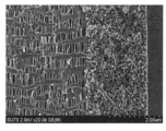
- Example 2 is an SEM photograph taken from the heat-resistant layer side of a composite porous membrane having the same configuration as in Example 1.
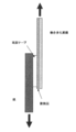
- 2 is an SEM photograph of a composite porous membrane having the same configuration as that of Example 1 taken from an MD cross section. It is a plot figure implemented when measuring 150 degreeC heat resistance. It is a plot figure which shows the measurement of tape adhesiveness.
- the present invention is a composite porous membrane composed of a heat-resistant layer made of an inorganic filler and a binder having a primary particle diameter of 5 nm to 100 nm and a microporous membrane made of a polyolefin resin.
- the microporous membrane used in the present invention is composed of a polyolefin resin.
- a polyolefin resin include polyethylene and polypropylene, and these copolymers, homopolymers, or copolymers may be used in a blend of two or more.
- Polyolefin resins such as polybutene-1, polyhexene-1, polyoctene-1, poly-4-methylpentene-1, polymethylpentene, 1,2-polybutadiene, and 1,4-polybutadiene can also be used.
- the weight average molecular weight (Mw) and molecular weight distribution (Mw / Mn) of the polyolefin resin may be any as long as they can produce a microporous membrane.
- the polypropylene resin used in the present invention is a crystalline polymer mainly composed of propylene polymerized units, and is preferably polypropylene having 90% by weight or more of propylene polymerized units. Specifically, it may be a homopolymer of propylene, or a random or block copolymer of 90% by weight or more of propylene polymer units and 10% by weight or less of ethylene or ⁇ -olefin.
- the olefin used when the crystalline polypropylene is a copolymer include ethylene, 1-butene, 1-pentene, 1-hexene, 1-octene, 1-decene, 1-dodecene and 4-methyl-1-pentene. , 3-methyl-1-pentene and the like. Among these, it is preferable from the point of manufacturing cost to use a propylene homopolymer.
- Examples of the polyethylene resin used in the present invention include an ethylene homopolymer, a random or block copolymer of two or more with a monomer other than ethylene mainly composed of ethylene, and a mixture of two or more of these. It is done.
- the main component means the most abundant component.
- the monomer other than ethylene is not particularly limited, but olefins having 3 to 12 carbon atoms such as propylene, 1-butene, 1-pentene, 1-hexene and 1-octene, vinyl esters such as vinyl acetate, acrylic Examples thereof include acrylic acid esters such as ethyl acid, methacrylic acid esters such as methyl methacrylate, and carbon monoxide. These may be used alone or in combination of two or more.
- polyolefin resins such as polypropylene resin and polyethylene resin of the present invention include antioxidants, neutralizers, inorganic fillers and antiblocking agents, lubricants, antistatic agents, ⁇ crystal nucleating agents used in ordinary polyolefin resins.
- antioxidants such as polypropylene resin and polyethylene resin of the present invention
- inorganic fillers and antiblocking agents such as antioxidants, neutralizers, inorganic fillers and antiblocking agents, lubricants, antistatic agents, ⁇ crystal nucleating agents used in ordinary polyolefin resins.
- a surfactant and the like can be blended as necessary.
- Antioxidants include tetrakis [methylene-3- (3 ′, 5′-di-t-butyl-4′-hydroxyphenyl) propionate] methane, 2,6-di-t-butyl-4-methylphenol, Phenolic compounds such as n-octadecyl-3- (3 ′, 5′-di-t-butyl-4′-hydroxyphenyl) propionate and tris (3,5-di-t-butyl-4-hydroxybenzyl) isocyanurate Antioxidant, or tris (2,4-di-t-butylphenyl) phosphite, tris (nonylphenyl) phosphite, distearyl pentaerythritol diphosphite, tetrakis (2,4-di-t-butylphenyl) Examples thereof include phosphorus antioxidants such as -4,4'-biphenylene-diphosphonite.
- neutralizing agents include higher fatty acid salts such as calcium stearate.
- inorganic fillers and anti-blocking agents include calcium carbonate, silica, hydrotalcite, zeolite, aluminum silicate, magnesium silicate, and the like.
- ⁇ crystal nucleating agents include talc, aluminum hydroxy-bis (4-t-butylbenzoate), 1,3: 2,4-dibenzylidene sorbitol, 1,3: 2,4-bis (p-methylbenzylidene) Sorbitol, 1,3: 2,4-bis (p-ethylbenzylidene) sorbitol, 1,3: 2,4-bis (2 ′, 4′-dimethylbenzylidene) sorbitol, 1,3: 2,4-bis ( 3 ′, 4′-dimethylbenzylidene) sorbitol, 1,3-p-chlorobenzylidene-2,4-p-methylbenzylidenesorbitol, 1,3: 2,4-bis (p-chlorobenzylidene) sorbitol, sodium-bis (4-t-butylphenyl) phosphate, sodium-2,2'-methylene-bis (4,6-di-t-butylphenyl)
- a method for producing a microporous membrane using the above polyolefin resin after forming a molten resin into a sheet, a dry lamellar structure is formed by heat treatment, and a microporous portion is formed by peeling a crystal interface by uniaxial or biaxial stretching.
- Typical method is a wet method in which a microporous part is formed by uniaxial or biaxial stretching after extraction and removal of the solvent after forming a sheet while maintaining microphase separation by heating and melting the resin and solvent As mentioned.
- those produced by a dry uniaxial stretching method are particularly preferably used.
- the inorganic filler used in the heat-resistant layer of the present invention is not particularly limited as long as it has a melting point of 200 ° C. or higher, high electrical insulation, and electrochemical stability.
- Specific examples include oxide ceramics such as alumina, silica, titania, zirconia, magnesia, barium titanate, hydroxide ceramics such as aluminum hydroxide and magnesium hydroxide, silicon nitride, titanium nitride, boron nitride, etc.
- Nitride based ceramics or materials derived from mineral resources such as boehmite, talc, kaolin, zeolite, apatite, halloysite, pyrophyllite, montmorillonite, sericite, mica, amicite, bentonite, calcium silicate, magnesium silicate, etc. . These may be used alone or in a mixture of two or more. Among these, it is preferable to use alumina, silica, titania, and boehmite.
- an inorganic filler whose surface is hydrophobized by introducing a functional group such as an alkyl group or a phenyl group using a surface modifier such as a silane coupling agent on the surface of the inorganic filler may be used.
- a method for qualitatively and quantitatively confirming the content of the inorganic filler used in the present invention a method of performing surface analysis of the inorganic fine particles on the surface layer of the composite porous membrane by fluorescent X-ray analysis, X-ray photoelectron spectroscopy, etc., composite porous Dissolve the thermoplastic resin that composes the membrane using a solvent that can dissolve, and separate the inorganic filler by filtration, centrifugation, etc., then surface analysis and atomic absorption method, ICP (high frequency inductive coupling) Examples of the method include elemental analysis by a method such as plasma emission spectroscopy. Of course, it is not limited to these illustrated methods, and can be confirmed by other methods. Furthermore, it is preferable to use these methods together because it is possible to determine whether it is one type of inorganic filler contained or a mixture of a plurality of inorganic fillers.
- the primary particle size of the inorganic filler is 5 nm to 100 nm, preferably 10 nm to 50 nm.
- the primary particle diameter is the minimum particle diameter of the inorganic filler, and the average particle diameter is the secondary particle diameter of a cluster composed of aggregates of primary particles.
- the inorganic filler is composed of a cluster composed of an aggregate of a plurality of primary particles, and the average particle diameter is preferably 0.3 ⁇ m or less. 0.05 ⁇ m to 0.3 ⁇ m is more preferable, and 0.05 ⁇ m to 0.1 ⁇ m is even more preferable.
- the average particle size in the above range, it is possible to suppress clogging of the microporous membrane and maintain air permeability, and to obtain a composite porous membrane excellent in adhesion with the microporous membrane. .
- Examples of the method for measuring the average particle diameter include a light scattering method, an image analysis method, a sedimentation method, and the like, but the average particle size in the present invention is measured using a laser diffraction scattering type particle size distribution measuring device, and the number of particles is measured. It is the value of the particle size at which the cumulative frequency is 50%.
- the shape of the inorganic filler for example, there are various things such as a spherical shape, an oval shape, a scale shape, a plate shape, a fiber shape, a tuft shape, and an indeterminate shape, but there is no particular limitation as long as it satisfies the requirements of the present invention. Can be used. Of these, spherical, plate-like, and tuft-like shapes are preferable for achieving both heat shrinkage suppression and adhesion improvement.
- a binder is added and mixed for the purpose of improving the adhesion to the inorganic filler and / or the microporous film.
- binders to be used include polyolefin resins such as polyethylene, polypropylene, and polybutadiene, polyvinylidene fluoride, polytetrafluoroethylene, polyvinylidene fluoride-hexafluoropropylene copolymer, and polyvinylidene fluoride-hexafluoropropylene-tetrafluoroethylene copolymer.
- fluorine-containing resin such as ethylene-tetrafluoroethylene copolymer, styrene-butadiene copolymer and its hydride, acrylonitrile-butadiene copolymer and its hydride, acrylonitrile-butadiene-styrene copolymer and its hydrogen , Methacrylic acid ester-acrylic acid ester copolymer, styrene-acrylic acid ester copolymer, acrylonitrile-acrylic acid ester copolymer, ethylene propylene rubber Copolymer resins such as ethyl cellulose, hydroxyethyl cellulose, carboxymethyl cellulose, etc., resins such as polyvinyl alcohol, polyamideimide, polyamide, poly-N-vinylacetamide, polyvinyl butyral, polyvinyl formal, etc. May be used.
- polyorganosiloxane may be mixed with an inorganic
- the weight fraction of the inorganic filler / binder in the heat-resistant layer is preferably 40/60 to 98/2, more preferably 50/50 to 95/5, although it depends on the specific gravity of the filler material. More preferably, it is 60/40 to 90/10. By setting it within this range, a composite porous membrane excellent in heat resistance can be obtained in which the adhesion between the filler and / or the microporous membrane and the air permeability of the composite porous membrane are balanced.
- the layer thickness of the heat-resistant layer is preferably 0.5 ⁇ m or more in order to maintain the heat resistance of the composite porous membrane, and is preferably 20 ⁇ m or less from the viewpoint of maintaining air permeability and adhesion. More preferably, it is 1 ⁇ m to 15 ⁇ m, and still more preferably 2 ⁇ m to 10 ⁇ m.
- the heat-resistant layer is not limited to one side of the microporous film, and may be laminated so as to be an intermediate layer of the heat-resistant layer / microporous film / heat-resistant layer and the microporous film / heat-resistant layer / microporous film. When heat-resistant layers are laminated on both sides, the layer thickness is the sum of the thicknesses laminated, and the heat-resistant layer may be laminated with the same thickness or different thicknesses.
- the microporous membrane used in the present invention preferably has a thickness of 5 to 50 ⁇ m, more preferably 10 to 30 ⁇ m, considering the balance between air permeability and heat resistance.
- the porosity is preferably 30 to 70%, more preferably 40% to 60%.
- the pore size is preferably a size having a maximum pore size of 35 to 50 nm and an average pore size of 10 to 30 nm as a size that causes little unevenness in permeability and is unlikely to be clogged.
- the air permeability by the Gurley method is preferably 30 to 600 sec / 100 cc, and more preferably 50 to 400 sec / 100 cc.
- the composite porous membrane having such a structure has a property of sufficiently suppressing thermal shrinkage even when the melting temperature of the polyolefin resin is exceeded, and has excellent adhesion between the heat-resistant layer and the microporous membrane.
- the film thickness of the composite porous membrane is determined according to the use such as a filter and a separator, but is preferably 5 ⁇ m to 150 ⁇ m. If it is in this range, it is preferable as a composite porous membrane from the viewpoints of air permeability, heat resistance, strength and the like. More preferably, it is 6 ⁇ m to 100 ⁇ m, and still more preferably 10 ⁇ m to 50 ⁇ m.
- the air permeability of the composite porous membrane is preferably 30 to 600 sec / 100 cc, preferably 50 to 400 sec / 100 cc, in consideration of the balance between strength and ion permeability as in the case of the microporous membrane itself. More preferably.
- the adhesion between the microporous membrane and the heat-resistant layer is good. Adhesion can be improved by uniformly adjusting the dispersion state of the inorganic filler and binder in the coating liquid, thereby suppressing the blockage of the microporous membrane and maintaining the air permeability. Can be prevented.
- the adhesion is in three stages: ⁇ : no dropout even when rubbed strongly, ⁇ : dropout when rubbed strongly, ⁇ : easy dropout when rubbed. When evaluated, depending on the application used, if it is ⁇ , ⁇ , it can be used sufficiently. More preferably, ⁇ : no drop is observed even when rubbed strongly.
- the adhesion of the composite porous membrane in the present invention is good not only for the adhesion between inorganic fillers but also for the adhesion between the heat-resistant layer and the microporous membrane.
- the former can be determined by suppressing the falling of the heat-resistant layer against friction (hereinafter referred to as frictional adhesion).
- the heat-resistant layer side is pasted by a technique such as tape, and is determined by the stress at the time of peeling. (Hereinafter referred to as tape adhesion).
- tape adhesion As an example, for measurement using a tensile tester, the composite porous membrane is cut to a certain length, and a double-sided pressure-sensitive adhesive tape is stuck on the heat-resistant layer.
- peel strength can be measured.
- the conditions are described in the examples. When the tape adhesion is evaluated according to the conditions, it is preferably 500 gf or more, more preferably 1000 gf or more, and still more preferably 2000 gf or more.
- the composite porous membrane of the present invention has a strength capable of sufficiently suppressing thermal shrinkage even when the melting temperature of the polyolefin resin is exceeded, and is excellent in heat resistance.
- the heat resistance can be evaluated using 150 ° C. heat resistance and 180 ° C. heat resistance based on thermal shrinkage at 150 ° C. and 180 ° C. If the heat resistance at 150 ° C. is a heat shrinkage rate of 19% or less, it will have a strength that can sufficiently suppress heat shrinkage, preferably 0% to 15%, more preferably 0% to 10%. is there.
- the heat resistance at 180 ° C. may be a heat shrinkage rate of 10% or less, preferably 0% to 8%, more preferably 0% to 5%.
- Heat shrinkage can be sufficiently suppressed if either of the heat shrinkage rates at both temperatures can be reduced, but it is preferable that the heat shrinkage rate at 180 ° C., which is a high temperature, is smaller, and more preferably, the heat shrinkage rate at both temperatures is smaller. .
- the microporous membrane manufactured by the above-mentioned method is used, and a heat resistant layer is laminated on one side or both sides of the microporous membrane, or a heat resistant layer is laminated so as to be an intermediate layer between two microporous membranes.
- a composite porous membrane can be obtained.
- a method of laminating the heat-resistant layer and the microporous membrane a method of separately producing the heat-resistant layer and the microporous membrane and laminating each of them, at least one kind of inorganic filler and binder on at least one side of the microporous membrane is used. Examples thereof include a method of forming a heat-resistant layer by applying a coating solution containing the same. When it is desired to form a thin heat-resistant layer, the latter method is preferable from the viewpoint of productivity.
- Specific methods for forming a heat-resistant layer by applying a coating solution containing at least two kinds of inorganic filler and binder on at least one surface of the microporous membrane include the following steps. (1) A water or polar organic solvent slurry in which 100 parts by weight of an inorganic filler is dispersed is mixed with a water or polar organic solvent solution containing 2 to 150 parts by weight of a binder, and a coating solution is prepared through a dispersion treatment. . Alternatively, 100 parts by weight of an inorganic filler is directly added and mixed while stirring a solution of water or a polar organic solvent containing 2 to 150 parts by weight of a binder, and then a coating solution is prepared through a dispersion treatment. (2) After coating the coating liquid on at least one surface of the microporous film to form a coated film, it is dipped and deposited in a poor solvent that does not dissolve the binder by hot air drying.
- a solvent for preparing a binder solution.
- the solvent include water or polar organic solvents such as acetone, N-methylpyrrolidone, dimethylacetamide, dimethylformamide, dimethylsulfoxide and the like.
- the solvent used as a poor solvent with respect to a binder can also be added. With the addition of such a poor solvent, a micro phase separation structure is induced, and a heat-resistant layer having pores can be formed.
- the pores of the heat-resistant layer are formed by a matrix composed of an inorganic filler and a binder.
- an inorganic filler is dispersed in this binder solution to obtain a coating solution.
- the method of addition is not particularly limited, and an inorganic filler may be separately dispersed in the same solvent as the binder solution, mixed with the binder solution, and used as a coating solution.
- a dispersant such as ammonium polyacrylate, an antibacterial agent such as benzalkonium chloride and cetylpyridinium chloride, or an antifungal agent is added as long as the effects of the present invention are not impaired. May be.
- the method of surface-treating an inorganic filler with a silane coupling agent etc. is applicable.
- the inorganic filler When dispersing the inorganic filler, it can be dispersed and prepared by stirring with a stirrer such as a disper, but by using a device that can be crushed and dispersed with high stress, such as a homogenizer, bead mill, jet mill, etc. A more uniform coating solution can be produced.
- a stirrer such as a disper
- high stress such as a homogenizer, bead mill, jet mill, etc.
- a more uniform coating solution can be produced.
- an inorganic filler with a very small primary particle diameter is inherently high in surface energy, so that it is easy to form agglomerated particles by agglomeration, and the remaining fine primary particles tend to cause clogging of the microporous film. Absent.
- massive particles are crushed and a plurality of primary particles are clustered in a uniform size.
- the binder and the cluster are uniformly dispersed in the coating liquid, so that it is possible to obtain a composite porous film having a heat-resistant layer that is closely packed and maintains a space between the clusters.
- the composite porous membrane of the present invention works synergistically with other structures by dispersing inorganic fillers with extremely small primary particle diameters in an appropriate and uniform size, and the fine primary particles are finely packed. Expected from the original effect of adding fine primary particles, while enjoying the effects of lowering heat shrinkage and improving heat resistance due to filling, and at the same time maintaining high adhesion to the microporous membrane and air permeability. It will have an excellent effect.
- the molecular chains constituting the binder in the course of the secondary dispersion treatment are cut by strong physical stress, thereby promoting uniform dispersion with an inorganic filler having a very small primary particle size.
- the weight average molecular weight (Mw) of the binder after the secondary dispersion treatment is 300,000 or more and 1,000,000 or less, and the molecular weight distribution (Mw / Mn) is 2.0.
- the coating liquid excellent in the adhesiveness between an inorganic filler and / or a microporous film can be obtained.
- the coating liquid obtained in (1) is applied to at least one side of the microporous membrane.
- the coating method include a knife coater method, a gravure coater method, a micro gravure coater method, a screen printing method, a Mayer bar method, a die coater method, a reverse roll coater method, an ink jet method, a spray method, and a roll coater method.
- the gravure coater method and the micro gravure coater method are preferable, and the die coater method in which the coating liquid does not come into contact with the outside air and wear due to the inorganic filler is also preferable.
- the microporous membrane is subjected to surface treatment on the surface of the microporous membrane for the purpose of promoting uniform penetration of the coating solution and improving the adhesion between the heat-resistant layer and the microporous membrane immediately before or just before coating. Is also preferable in order to achieve the object of the present invention.
- the surface treatment method is not particularly limited as long as the porous structure on the surface of the microporous membrane is not significantly impaired. Specific examples include corona discharge treatment, plasma treatment, mechanical surface-roughening method, solvent treatment method, acid treatment method. And an oxidation method by ultraviolet irradiation.
- Film thickness A composite porous membrane is cut into a circular shape with a diameter of 72 mm, and a dial gauge (measuring element diameter of 5 mm, measurement load of 1.5 N) is used, and any 15 locations are measured in accordance with JIS K 7130 (1992) A-2 method. The thickness was measured. The average value of the 15 values was taken as the film thickness.
- Average particle diameter The average particle diameter was measured using LA-950 manufactured by HORIBA, which is a laser diffraction / scattering particle size distribution measuring apparatus, and the cumulative frequency of the number of particles was 50% (median diameter: d50). ) was calculated.
- the primary particle diameter was measured by measuring the surface or cross section of the heat-resistant layer from an image obtained by a scanning electron microscope (SEM), measuring 100 particles with an image analyzer, and calculating the average particle diameter.
- SEM scanning electron microscope
- Friction adhesion was checked based on the following criteria after the panel rubbed the surface of the heat-resistant layer with fingers. ⁇ : The inorganic filler does not fall off even when rubbed strongly ⁇ : The inorganic filler comes off when rubbed strongly ⁇ : The inorganic filler easily falls off when rubbed
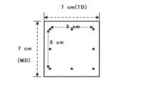
- tape adhesion Confirmation of tape adhesion was determined by measuring the stress at the time of tape peeling with a tensile tester.
- the composite porous membrane is cut to 2 cm (TD) ⁇ 7 cm (MD), and a double-sided adhesive tape (Sumitomo 3M Co., Ltd., PPS-10: width 1 cm), which is also cut to a length of 2 cm, is applied onto the heat-resistant layer.
- a double-sided adhesive tape (Sumitomo 3M Co., Ltd., PPS-10: width 1 cm)
- kraft paper cut to 2 cm wide x 7 cm long was affixed to one side of the adhesive tape, the composite porous membrane and the edge of the paper were each sandwiched between chucks, and the heat resistant layer / microporous membrane was pulled at a pulling speed of 500 mm / min.
- the interfacial peel strength (gf) was measured (see the plot diagram in FIG. 4).
- TMA thermo mechanical analysis: TMA / SS7100E manufactured by SII Nano Technology Co., Ltd.
- TMA thermal mechanical analysis: TMA / SS7100E manufactured by SII Nano Technology Co., Ltd.
- a sample cut to MD15 mm ⁇ TD3 mm was set in a cell with a constant load of 100 mN, and from room temperature to 5 ° C./min. The temperature was raised to 200 ° C., and the thermal shrinkage at 180 ° C. was measured (180 ° C. heat resistance).
- Air permeability The air permeability of the composite porous membrane was measured using a Gurley-type densometer (air permeability tester) manufactured by Toyo Seiki Seisakusho, based on JIS P8117.
- the molecular weight of the binder was measured using a gel permeation chromatography (GPC) apparatus.
- the molecular weight distribution (Mw / Mn) was calculated from the number average molecular weight (Mn) and the weight average molecular weight (Mw) determined by GPC measurement.
- the GPC apparatus uses PU-2080 Plus manufactured by JASCO Corporation as a pump, 830-RI manufactured by JASCO Corporation as a detector, and 8.0 mm of Shodex KF-805L + KF-806M heated in a 35 ° C. oven in a column. A total of two (ID) ⁇ 300 mm (L) columns were used.
- Dimethylformamide (DMF) was used as an eluent, and measurement was performed under a flow rate condition of 1 ml / min.
- Example 1 Preparation of coating solution
- NMP N-methylpyrrolidone
- Kynar Flex polyvinylidene fluoride 2801, manufactured by Arkema Co., Ltd.
- Mw 579,000
- Mw / Mn 2.28 from GPC measurement
- An NMP solution having a weight concentration of 4% was prepared.
- JNC-Cell (registered trademark, thickness 20 ⁇ m, maximum pore size ⁇ 30 nm, porosity 48%, air permeability 250 sec / 100 ml), which is a JNC PP separator, was used as the polyolefin microporous membrane.
- N 2 plasma was irradiated as a pretreatment, and then the coating liquid was applied using a micro gravure and dried with a dryer to obtain a composite porous membrane.
- the obtained composite porous membrane had a thickness of 24 ⁇ m and an air permeability of 260 sec / 100 ml.
- Example 2 Implemented except that SiO 2 (AEROSIL (registered trademark) MOX80: primary particle size 50 nm, manufactured by Nippon Aerosil Co., Ltd.) is used as the inorganic filler, and the slurry is further treated three times at a treatment pressure of 200 MPa using a jet mill.
- a coating solution was prepared in the same manner as in Example 1, and applied to the microporous membrane to obtain a composite porous membrane. Under these conditions, since the average particle size could not be measured with the laser diffraction / scattering particle size distribution analyzer, only the primary particle size was measured by SEM observation.
- the physical property values of the obtained composite porous membrane are shown in Table 1.
- Example 3 Other than using Al 2 O 3 (AEROXIDE (registered trademark) AluC: primary particle diameter 15 nm) manufactured by Nippon Aerosil Co., Ltd.) as the inorganic filler, and further processing the slurry once at a processing pressure of 200 Mpa using a jet mill.
- AEROXIDE registered trademark
- AluC primary particle diameter 15 nm
- a jet mill Prepared a coating liquid by the same method as in Example 1, and the average particle diameter of Al 2 O 3 particles in the coating liquid was 0.07 ⁇ m, and the resultant was applied to a microporous film to form a composite porous film.
- Table 1 The physical property values of the obtained composite porous membrane are shown in Table 1.
- Example 4 Polyvinylidene fluoride (Kynar HSV500 manufactured by Arkema Co., Ltd .; Mw: 885,000, Mw / Mn: 2.47) as a binder was dissolved in N-methylpyrrolidone (NMP), and an NMP solution having a weight concentration of 3% Was made.
- NMP N-methylpyrrolidone
- Al 2 O 3 (AEROXIDE (registered trademark) AluC: primary particle diameter: 15 nm) manufactured by Nippon Aerosil Co., Ltd. was added to this and mixed so that the weight concentration was 9%, and an NMP slurry having a filler / binder weight ratio of 3: 1. Was further stirred using a disper at a rotation speed of 300 rpm for 1 hour.
- JNC-Cell registered trademark, film thickness: 15 ⁇ m, maximum pore size ⁇ 30 nm, porosity: 52%, air permeability: 170 sec / 100 ml
- a membrane was prepared.
- the physical property values of the obtained composite porous membrane are shown in Table 1.
- Example 5 Polyvinylidene fluoride (Kynar HSV900 manufactured by Arkema Co., Ltd .; Mw: 1,091,000, Mw / Mn; 2.02) as a binder was dissolved in N-methylpyrrolidone (NMP) at a weight concentration of 2.4. % NMP solution was prepared.
- NMP N-methylpyrrolidone
- Boehmite Boehmite C06 manufactured by Daimei Chemical Co., Ltd .: primary particle size 100 nm
- JNC-Cell registered trademark, film thickness: 15 ⁇ m, maximum pore size ⁇ 30 nm, porosity: 47%, air permeability: 220 sec / 100 ml
- a membrane was prepared. Table 2 shows physical property values of the obtained composite porous membrane.
- NMP N-methylpyrrolidone
- a copolymerized polyvinylidene fluoride Kynar 2801 manufactured by Arkema Co., Ltd.
- AEROXIDE AluC primary particle diameter: 15 nm
- SG-ALO100UP primary particle diameter: 110 nm
- An NMP slurry with a filler / binder weight ratio of 2: 1 was prepared.
- Example 7 Example 1 except that JNC-Cell (registered trademark, film thickness 15 ⁇ m, maximum pore size ⁇ 30 nm, porosity 49%, air permeability 180 sec / 100 ml), a JNC PP separator, was used as the polyolefin microporous membrane.
- a composite porous membrane was prepared by the method described above. Table 2 shows physical property values of the obtained composite porous membrane.
- Boehmite (DISAL (registered trademark) 10C manufactured by SASOL: primary particle size 50 nm) is used as an inorganic filler, a jet mill is prepared at 200 Mpa once, and the average particle size of boehmite in the coating solution is 0.3 ⁇ m.
- a composite porous membrane was prepared in the same manner as in Example 1 except that. Table 2 shows physical property values of the obtained composite porous membrane. The adhesion was slightly lower than that of Example 1, and dropping was observed with strong finger rubbing. The heat resistance at 180 ° C. was sufficient, but the heat resistance at 150 ° C. was slightly low.
- Example 9 Example 1 Except that an NMP slurry was prepared in the same process as Example 1, and then a coating solution was prepared by stirring only with a disper (8000 rpm, 1 hour), and the average particle size of boehmite in the coating solution was set to 10 ⁇ m.
- a composite porous membrane was prepared in the same manner as described above. Table 2 shows physical property values of the obtained composite porous membrane. The adhesiveness of the obtained composite porous membrane was slightly lower than that of Example 1, and it was detached by strong finger rubbing. The heat resistance at 180 ° C. was sufficient, but the heat resistance at 150 ° C. was slightly low.
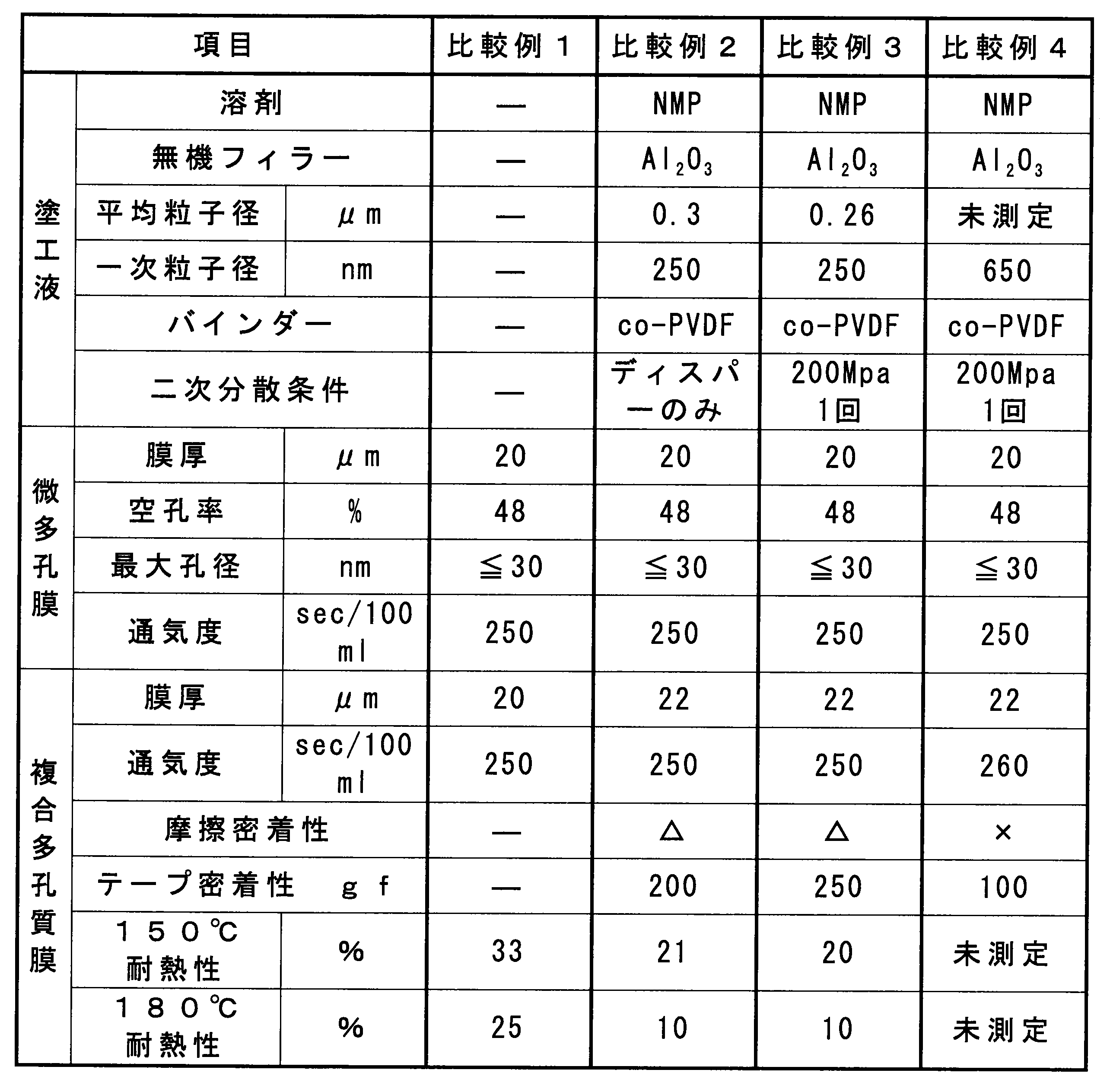
- Example 1 The microporous film used in Example 1 was evaluated for heat resistance without a heat-resistant layer coating.
- Table 3 shows the physical property values of the obtained composite porous membrane.
- Comparative Example 3 Except for performing the treatment once at a treatment pressure of 200 Mpa using a jet mill, it was prepared in the same manner as in Comparative Example 2, the average particle diameter of Al 2 O 3 particles in the coating solution was 0.26 ⁇ m, A composite porous membrane was formed by coating on a microporous membrane. Table 3 shows the physical property values of the obtained composite porous membrane. The shrinkage rate at 150 ° C. for 2 hours (150 ° C. heat resistance) was 20%, and 10% under the conditions (180 ° C. heat resistance) placed in an atmosphere at 180 ° C.
- Example 4 Al 2 O 3 particles having a primary particle size of 650 nm were prepared in the same manner as in Example 1 except that they were processed once at a processing pressure of 200 Mpa using a jet mill, and applied to a microporous membrane. Thus, a composite porous membrane was obtained. Table 3 shows the physical property values of the obtained composite porous membrane. The obtained microporous film had low adhesion and easily dropped off when rubbed with a finger. Therefore, heat resistance at 150 ° C. and heat resistance at 180 ° C. were not measured.
- the composite porous membrane of the present invention sufficiently suppresses thermal shrinkage even under conditions where the temperature rises above the melting temperature, enhances the adhesion between the microporous membrane and the heat-resistant layer, and removes the inorganic filler. Can also be suppressed. In addition, since the falling off of the inorganic filler can be suppressed, it can contribute to the improvement of productivity. Since heat resistance is good, especially when it is set as a separator, the short circuit prevention between electrodes can be maintained.
- the composite porous membrane of the present invention can be used as a porous membrane used for filters and separators used under high temperature conditions.
Landscapes
- Chemical & Material Sciences (AREA)
- Chemical Kinetics & Catalysis (AREA)
- General Chemical & Material Sciences (AREA)
- Electrochemistry (AREA)
- Engineering & Computer Science (AREA)
- Medicinal Chemistry (AREA)
- Polymers & Plastics (AREA)
- Organic Chemistry (AREA)
- Health & Medical Sciences (AREA)
- Materials Engineering (AREA)
- Inorganic Chemistry (AREA)
- Composite Materials (AREA)
- Manufacturing & Machinery (AREA)
- Cell Separators (AREA)
- Laminated Bodies (AREA)
- Manufacture Of Porous Articles, And Recovery And Treatment Of Waste Products (AREA)
Description
[1]無機フィラーとバインダーとからなる耐熱層と、ポリオレフィン樹脂からなる微多孔膜とで構成された複合多孔質膜であって、無機フィラーの一次粒子径が5nm~100nmであることを特徴とする複合多孔質膜。
[2]耐熱層を構成する無機フィラーが、アルミナ、ベーマイト、シリカ及びチタニアよりなる群から選ばれた少なくとも1種であることを特徴とする[1]に記載の複合多孔質膜。
[3]耐熱層を構成する無機フィラーが、複数の一次粒子の集合体で構成されたものであり、集合体の平均粒子径が0.3μm以下であることを特徴とする[1]または[2]に記載の複合多孔質膜。
[4]複合多孔質膜を構成する微多孔膜が、乾式一軸延伸法により作製された[1]~[3]のいずれか1つに記載の複合多孔質膜。
[5]微多孔膜を構成するポリオレフィン樹脂が、ポリプロピレンである[1]~[4]のいずれか1つに記載の複合多孔質膜。
(1)無機フィラー100重量部を分散させた水または極性有機溶媒のスラリーに、バインダーを2~150重量部含んだ水または極性有機溶媒の溶液を混合、分散処理を経て塗工液を調製する。或いは、バインダーを2~150重量部含んだ水または極性有機溶媒の溶液を攪拌させながら、無機フィラー100重量部を直接添加、混合させた後分散処理を経て塗工液を調製する。
(2)該塗工液を微多孔膜の少なくとも片面に塗工して塗工膜を形成した後、熱風乾燥あるいはバインダーを溶解しない貧溶媒中に浸漬・析出させる。
先に列挙した各種バインダーの少なくとも1種を溶媒に溶かし、バインダー溶液を作成する。溶媒は水またはアセトン、N-メチルピロリドン、ジメチルアセトアミド、ジメチルホルムアミド、ジメチルスルホキシド等の極性有機溶媒が挙げられる。また、バインダーに対し貧溶媒となる溶剤を添加することもできる。このような貧溶媒の添加に伴い、ミクロ相分離構造が誘発され、空孔部を形成した耐熱層を形成させることができる。特に本発明のように一次粒子径が極めて微小な無機フィラーを用いる場合、耐熱層の空孔部は無機フィラー及びバインダーからなるマトリックスにより形成されることとなるため、耐熱性のみならず通気性や電解液等の保液性向上にも繋がり好ましい。貧溶剤としてはアルコール類が好適であり、特にグリコールの様な多価アルコールが好適である。更に、極性有機溶媒を主体とした溶液の場合、貧溶媒として水を添加してもよい。このバインダー溶液に、必要量の無機フィラーを分散させて塗工液とする。添加の手法については特に限定されることはなく、別途無機フィラーをバインダー溶液と同じ溶媒中に分散後、バインダー溶液と混合、塗工液としてもよい。
(1)で得られた塗工液を、微多孔膜の少なくとも一方の片面に塗工する。微多孔膜の両面に耐熱層を形成する場合は、両面同時に塗工することが工程の短縮という観点から好ましい。塗工方法としては、ナイフコーター法、グラビアコーター法、マイクログラビアコーター法、スクリーン印刷法、マイヤーバー法、ダイコーター法、リバースロールコーター法、インクジェット法、スプレー法、ロールコーター法等が挙げられる。この中でも、均一性の観点からグラビアコーター法、マイクログラビアコーター法が好ましく、また、塗工液が外気と接触せず、無機フィラーによる磨耗が少ないダイコーター法も好ましい。
○:強く擦っても無機フィラーの脱落が見られない
△:強く擦ると無機フィラーの脱落が見られる
×:擦ると容易に無機フィラーの脱落が見られる
(塗工液の調製)
N-メチルピロリドン(NMP)に、バインダーとして共重合ポリフッ化ビニリデン(アルケマ(株)製 Kynar Flex(登録商標) 2801;GPC測定よりMw;579,000、Mw/Mn;2.28)を溶解、重量濃度4%のNMP溶液を作製した。これにベーマイト(大明化学(株)製 ベーマイトC01:一次粒子径30nm)を重量濃度8%となる様に添加、混合してフィラー/バインダー重量比2:1のNMPスラリーを作製、更にディスパーを用いて回転速度300rpmにて1時間攪拌を実施した。得られたスラリーの平均粒子径はd50=11μmであった。更にスラリーを、ジェットミルを用いて200Mpaの処理圧にて5回処理を行い、無機フィラー濃度8重量%、バインダー濃度4重量%の塗工液を1000g調製した。得られた塗工液中のベーマイトの平均粒子径はd50=0.08μmであった。また、GPCを用い同条件にて処理したバインダーの分子量を測定した所、Mwは約320,000であり、Mw/Mnは1.46であった。
ポリオレフィン微多孔膜として、JNC製PPセパレータであるJNC-Cell(登録商標、厚さ20μm、最大孔径≦30nm、空孔率48%、通気度250sec/100ml)を用いた。これに前処理としてN2プラズマを照射後、前記塗工液をマイクログラビアを用いて塗工、ドライヤーにて乾燥させて複合多孔質膜を得た。得られた複合多孔質膜の膜厚は24μm、通気度は260sec/100mlであった。摩擦密着性は○:強く擦っても脱落が見られないものであり、テープ密着性は3500gf、150℃耐熱性は8%、180℃耐熱性は3%であった。これらをまとめて表1に示す。
無機フィラーとしてSiO2(日本アエロジル(株)製 AEROSIL(登録商標) MOX80:一次粒子径50nm)を使用し、更にスラリーを、ジェットミルを用いて200Mpaの処理圧にて3回処理する以外は実施例1と同様の手法で塗工液を作製、微多孔膜に塗工して複合多孔質膜とした。本条件において、レーザー回折散乱方式粒度分布測定装置では平均粒子径を測定できなかったため、SEM観察による一次粒子径の測定のみを行なった。得られた複合多孔質膜の物性値を表1に示す。
無機フィラーとしてAl2O3(日本アエロジル(株)製 AEROXIDE(登録商標) AluC:一次粒子径15nm)を使用し、更にスラリーを、ジェットミルを用いて200Mpaの処理圧にて1回処理する以外は実施例1と同様の手法で塗工液を作製、塗工液中のAl2O3粒子の平均粒子径を0.07μmとし、微多孔膜に塗工して複合多孔質膜とした。得られた複合多孔質膜の物性値を表1に示す。
N-メチルピロリドン(NMP)に、バインダーとしてポリフッ化ビニリデン(アルケマ(株)製 Kynar HSV500;GPC測定よりMw;885,000、Mw/Mn;2.47)を溶解、重量濃度3%のNMP溶液を作製した。これにAl2O3(日本アエロジル(株)製 AEROXIDE(登録商標) AluC:一次粒子径15nm)を重量濃度9%となる様に添加、混合してフィラー/バインダー重量比3:1のNMPスラリーを作製、更にディスパーを用いて回転速度300rpmにて1時間攪拌を実施した。得られたスラリーの平均粒子径はd50=11μmであった。更にスラリーを、ジェットミルを用いて200Mpaの処理圧にて1回処理を行い、無機フィラー濃度9重量%、バインダー濃度3重量%の塗工液を1000g調製した。得られた塗工液中のAl2O3の平均粒子径はd50=0.11μmであった。これにポリオレフィン微多孔膜として、JNC-Cell(登録商標、膜厚15μm、最大孔径≦30nm、空孔率52%、通気度170sec/100ml)を用い、実施例1と同様の手法で複合多孔質膜を作製した。得られた複合多孔質膜の物性値を表1に示す。
N-メチルピロリドン(NMP)に、バインダーとしてポリフッ化ビニリデン(アルケマ(株)製 Kynar HSV900;GPC測定よりMw;1,091,000、Mw/Mn;2.02)を溶解、重量濃度2.4%のNMP溶液を作製した。これにベーマイト(大明化学(株)製 ベーマイトC06:一次粒子径100nm)を重量濃度9.6%となる様に添加、混合してフィラー/バインダー重量比4:1のNMPスラリーを作製、更にディスパーを用いて回転速度300rpmにて1時間攪拌を実施した。得られたスラリーの平均粒子径はd50=15.5μmであった。更にスラリーを、ジェットミルを用いて200Mpaの処理圧にて3回処理を行い、無機フィラー濃度9.6重量%、バインダー濃度2.4重量%の塗工液を1000g調製した。得られた塗工液中のベーマイトの平均粒子径はd50=0.30μmであった。これにポリオレフィン微多孔膜として、JNC-Cell(登録商標、膜厚15μm、最大孔径≦30nm、空孔率47%、通気度220sec/100ml)を用い、実施例1と同様の手法で複合多孔質膜を作製した。得られた複合多孔質膜の物性値を表2に示す。
N-メチルピロリドン(NMP)に、バインダーとして共重合ポリフッ化ビニリデン(アルケマ(株)製 Kynar 2801)を溶解、重量濃度4%のNMP溶液を作製した。これに異なる粒子径のAl2O3としてAEROXIDE AluC(一次粒子径:15nm)を重量濃度4%、SG-ALO100UP(一次粒子径:110nm)を重量濃度4%となる様に混合・添加してフィラー/バインダー重量比2:1のNMPスラリーを作製した。更にディスパーを用いて回転速度300rpmにて1時間攪拌を実施した後、ジェットミルを用いて170Mpaの処理圧にて1回処理を行い、無機フィラー濃度8重量%、バインダー濃度4重量%の塗工液を1000g調製した。これにポリオレフィン微多孔膜として、JNC-Cell(登録商標、膜厚21μm、最大孔径≦30nm、空孔率53%、通気度150sec/100ml)を用い、実施例1と同様の手法で複合多孔質膜を作製した。得られた複合多孔質膜の物性値を表2に示す。
ポリオレフィン微多孔膜として、JNC製PPセパレータであるJNC-Cell(登録商標、膜厚15μm、最大孔径≦30nm、空孔率49%、通気度180sec/100ml)を用いた以外は実施例1と同様の手法で複合多孔質膜を作製した。得られた複合多孔質膜の物性値を表2に示す。
無機フィラーとしてベーマイト(SASOL社製 DISPAL(登録商標)10C:一次粒子径50nm)を用い、ジェットミルを200Mpa、1回処理にて調製し、塗工液中のベーマイトの平均粒子径を0.3μmとした以外は実施例1と同様の手法で複合多孔質膜を作製した。得られた複合多孔質膜の物性値を表2に示す。密着性は実施例1と比べやや低く、強い指擦りで脱落が見られた。180℃耐熱性は十分であるが、150℃耐熱性はやや低いものであった。
[実施例9]
実施例1と同じ工程でNMPスラリーを作製後、ディスパーのみの攪拌(8000rpm、1時間)で塗工液を作製し、塗工液中のベーマイトの平均粒子径を10μmとした以外は実施例1と同様の手法で複合多孔質膜を作製した。得られた複合多孔質膜の物性値を表2に示す。得られた複合多孔質膜の密着性は実施例1と比べやや低く、強い指擦りで脱落が見られた。180℃耐熱性は十分であるが、150℃耐熱性はやや低いものであった。
実施例1で用いた微多孔膜を、耐熱層コート無しで耐熱性を評価した。150℃、2時間における収縮率(150℃耐熱性)は33%であり、180℃雰囲気下に置いた条件(180℃耐熱性)では25%であった。得られた複合多孔質膜の物性値を表3に示す。
一次粒子径が250nmであるAl2O3粒子(SASOL社製 CERALOX(登録商標)APA-0.5)を、ディスパーのみの攪拌(8000rpm、1時間)とした以外は、実施例1と同様の手法で作製、塗工液中のAl2O3粒子の平均粒子径を0.3μmとし、微多孔膜に塗工して複合多孔質膜とした。得られた複合多孔質膜の物性値を表3に示す。150℃、2時間における収縮率(150℃耐熱性)は21%と20%を超え、180℃雰囲気下に置いた条件(180℃耐熱性)では10%であった。
ジェットミルを用いて200Mpaの処理圧にて1回処理を行なった以外は、比較例2と同様の手法で作製、塗工液中のAl2O3粒子の平均粒子径を0.26μmとし、微多孔膜に塗工して複合多孔質膜とした。得られた複合多孔質膜の物性値を表3に示す。150℃、2時間における収縮率(150℃耐熱性)は20%であり、180℃雰囲気下に置いた条件(180℃耐熱性)では10%であった。
一次粒子径が650nmであるAl2O3粒子を、ジェットミルを用いて200Mpaの処理圧にて1回処理を行なった以外は、実施例1と同様の手法で作製、微多孔膜に塗工して複合多孔質膜とした。得られた複合多孔質膜の物性値を表3に示す。得られた微多孔膜の密着性は低く、指で擦ると容易に脱落したので、150℃耐熱性、180℃耐熱性は測定しなかった。


Claims (5)
- 無機フィラーとバインダーとからなる耐熱層と、ポリオレフィン樹脂からなる微多孔膜とで構成された複合多孔質膜であって、無機フィラーの一次粒子径が5nm~100nmであることを特徴とする複合多孔質膜。
- 耐熱層を構成する無機フィラーが、アルミナ、ベーマイト、シリカ及びチタニアよりなる群から選ばれた少なくとも1種であることを特徴とする請求項1に記載の複合多孔質膜。
- 耐熱層を構成する無機フィラーが、複数の一次粒子の集合体で構成されたものであり、集合体の平均粒子径が0.3μm以下であることを特徴とする請求項1または2に記載の複合多孔質膜。
- 複合多孔質膜を構成する微多孔膜が、乾式一軸延伸法により作製された請求項1~3のいずれか1項に記載の複合多孔質膜。
- 微多孔膜を構成するポリオレフィン樹脂が、ポリプロピレンである請求項1~4のいずれか1項に記載の複合多孔質膜。
Priority Applications (5)
| Application Number | Priority Date | Filing Date | Title |
|---|---|---|---|
| KR1020157006625A KR101698370B1 (ko) | 2012-08-23 | 2013-07-30 | 우수한 내열성을 갖는 복합 다공성막 |
| EP13831040.4A EP2889134A4 (en) | 2012-08-23 | 2013-07-30 | POROUS COMPOSITE FILM HAVING EXCELLENT HEAT RESISTANCE |
| CN201380043852.2A CN104582949B (zh) | 2012-08-23 | 2013-07-30 | 耐热性优良的复合多孔质膜 |
| JP2014531563A JP5741982B2 (ja) | 2012-08-23 | 2013-07-30 | 耐熱性に優れた複合多孔質膜 |
| US14/422,000 US9748542B2 (en) | 2012-08-23 | 2013-07-30 | Composite porous film having excellent heat resistance |
Applications Claiming Priority (2)
| Application Number | Priority Date | Filing Date | Title |
|---|---|---|---|
| JP2012-183822 | 2012-08-23 | ||
| JP2012183822 | 2012-08-23 |
Publications (1)
| Publication Number | Publication Date |
|---|---|
| WO2014030507A1 true WO2014030507A1 (ja) | 2014-02-27 |
Family
ID=50149817
Family Applications (1)
| Application Number | Title | Priority Date | Filing Date |
|---|---|---|---|
| PCT/JP2013/070592 Ceased WO2014030507A1 (ja) | 2012-08-23 | 2013-07-30 | 耐熱性に優れた複合多孔質膜 |
Country Status (7)
| Country | Link |
|---|---|
| US (1) | US9748542B2 (ja) |
| EP (1) | EP2889134A4 (ja) |
| JP (1) | JP5741982B2 (ja) |
| KR (1) | KR101698370B1 (ja) |
| CN (1) | CN104582949B (ja) |
| TW (1) | TWI568490B (ja) |
| WO (1) | WO2014030507A1 (ja) |
Cited By (11)
| Publication number | Priority date | Publication date | Assignee | Title |
|---|---|---|---|---|
| CN105169829A (zh) * | 2015-08-26 | 2015-12-23 | 浙江宇邦滤材科技有限公司 | 一种芳纶超细纤维针刺滤袋及其制备方法 |
| WO2016143798A1 (ja) * | 2015-03-12 | 2016-09-15 | Jnc株式会社 | 有機・無機複合膜及びこれを用いた多層耐熱セパレータ材 |
| JP2016183209A (ja) * | 2015-03-25 | 2016-10-20 | 三菱樹脂株式会社 | 積層多孔フィルム、非水電解液二次電池用セパレータ、及び非水電解液二次電池 |
| WO2017073598A1 (ja) * | 2015-10-30 | 2017-05-04 | Jnc株式会社 | 平滑性に優れた有機・無機複合膜及びこれを用いた多層耐熱セパレータ材 |
| JP2017123330A (ja) * | 2016-01-08 | 2017-07-13 | 三星エスディアイ株式会社Samsung SDI Co., Ltd. | 耐熱層を含む分離膜、これを用いた二次電池およびこれらの製造方法 |
| JP2019046586A (ja) * | 2017-08-30 | 2019-03-22 | 旭化成株式会社 | 非水電解質電池用添加剤及びこれを用いた非水電解質電池 |
| WO2019244643A1 (ja) * | 2018-06-20 | 2019-12-26 | 日本ゼオン株式会社 | 二次電池機能層用スラリーの製造方法 |
| JP2020537307A (ja) * | 2017-10-13 | 2020-12-17 | オプトドット コーポレイション | 多層ナノ多孔質セパレータ |
| JPWO2020246497A1 (ja) * | 2019-06-04 | 2021-09-13 | 帝人株式会社 | 非水系二次電池用セパレータ及び非水系二次電池 |
| WO2021200083A1 (ja) * | 2020-03-31 | 2021-10-07 | 日本ゼオン株式会社 | 電気化学素子機能層用組成物、電気化学素子用積層体、および電気化学素子 |
| JP2025525736A (ja) * | 2022-08-02 | 2025-08-07 | アムテック リサーチ インターナショナル エルエルシー | セラミック-変性、酸-補足性ポリオレフィンセパレーター |
Families Citing this family (17)
| Publication number | Priority date | Publication date | Assignee | Title |
|---|---|---|---|---|
| CN104157816A (zh) * | 2014-08-25 | 2014-11-19 | 深圳市星源材质科技股份有限公司 | 无机纳米粒子杂化聚烯烃微孔膜及其制备方法 |
| KR102588911B1 (ko) * | 2015-07-02 | 2023-10-16 | 데이진 가부시키가이샤 | 비수계 이차전지용 세퍼레이터, 비수계 이차전지 및 비수계 이차전지의 제조 방법 |
| HUE071713T2 (hu) * | 2015-11-11 | 2025-09-28 | Lg Energy Solution Ltd | Elektróda adhezív réteget tartalmazó szeparátor és az azt tartalmazó elektrokémiai eszköz |
| CN105374971A (zh) * | 2015-11-30 | 2016-03-02 | 江苏华东锂电技术研究院有限公司 | 一种锂离子电池隔膜及其制备方法 |
| KR102218038B1 (ko) * | 2016-06-08 | 2021-02-19 | 주식회사 엘지화학 | 세퍼레이터 및 이를 포함하는 전기화학소자 |
| PL3460873T3 (pl) * | 2017-01-26 | 2023-01-02 | Lg Energy Solution, Ltd. | Sposób wytwarzania separatora, separator tak wytworzony i zawierające go urządzenie elektrochemiczne |
| CN111279526A (zh) * | 2017-09-15 | 2020-06-12 | 赛昂能源有限公司 | 用于电化学电池的保护膜 |
| JP6992390B2 (ja) * | 2017-10-06 | 2022-02-04 | 株式会社Gsユアサ | 蓄電素子の製造方法及び蓄電素子 |
| CN108711605A (zh) * | 2018-07-10 | 2018-10-26 | 深圳中兴新材技术股份有限公司 | 一种复合电池隔膜、制备方法和电池 |
| CN108963161B (zh) * | 2018-07-10 | 2021-05-14 | 福建师范大学 | 含有二价磷酸盐和磷碳价键的涂覆膜制备方法 |
| CN113441019A (zh) | 2020-03-24 | 2021-09-28 | 中昊晨光化工研究院有限公司 | 一种聚四氟乙烯复合过滤材料及其制法与应用 |
| JP7474115B2 (ja) * | 2020-05-28 | 2024-04-24 | 帝人株式会社 | 非水系二次電池用セパレータ及び非水系二次電池 |
| CN115668626A (zh) * | 2020-05-28 | 2023-01-31 | 帝人株式会社 | 非水系二次电池用隔膜及非水系二次电池 |
| JP7798030B2 (ja) * | 2020-09-17 | 2026-01-14 | 株式会社レゾナック | 塗工液組成物、塗工膜付基材、セパレータ、二次電池および電極材料 |
| KR20230118078A (ko) | 2020-12-04 | 2023-08-10 | 로저스코포레이션 | 열 폭주 방지용 다층 시트 |
| CN114984769A (zh) * | 2022-06-09 | 2022-09-02 | 万华化学集团股份有限公司 | 一种含氟聚合物中空纤维疏水多孔膜及其制备方法 |
| JP7785202B2 (ja) * | 2022-06-24 | 2025-12-12 | 香港時代新能源科技有限公司 | セパレータ、その製造方法、並びに、それに関連する二次電池及び電力消費装置 |
Citations (12)
| Publication number | Priority date | Publication date | Assignee | Title |
|---|---|---|---|---|
| JP2002541644A (ja) * | 1999-04-09 | 2002-12-03 | ビーエーエスエフ アクチェンゲゼルシャフト | 電気化学的電池の隔壁板用複合材料 |
| JP2004227972A (ja) * | 2003-01-24 | 2004-08-12 | Sumitomo Chem Co Ltd | 非水電解液二次電池用セパレータ |
| WO2006123798A1 (ja) * | 2005-05-20 | 2006-11-23 | Sumitomo Chemical Company, Limited | 多孔質フィルムおよび積層多孔質フィルム |
| JP2008123996A (ja) | 2006-10-16 | 2008-05-29 | Hitachi Maxell Ltd | 非水電解質電池用セパレータおよび非水電解質電池 |
| WO2008123331A1 (ja) * | 2007-03-23 | 2008-10-16 | Sumitomo Chemical Company, Limited | セパレータ |
| JP2010123465A (ja) | 2008-11-21 | 2010-06-03 | Hitachi Maxell Ltd | 電池用セパレータおよびリチウム二次電池 |
| WO2010104077A1 (ja) * | 2009-03-09 | 2010-09-16 | 旭化成イーマテリアルズ株式会社 | 積層セパレータ、ポリオレフィン微多孔膜、及び蓄電デバイス用セパレータ |
| JP2011154936A (ja) | 2010-01-28 | 2011-08-11 | Hitachi Maxell Ltd | 電池用セパレータおよびリチウム二次電池 |
| JP2011258462A (ja) * | 2010-06-10 | 2011-12-22 | Du pont teijin advanced paper co ltd | 非水系電気電子部品用薄葉材 |
| JP2012003938A (ja) | 2010-06-17 | 2012-01-05 | Hitachi Maxell Ltd | 電池用セパレータおよびリチウム二次電池 |
| WO2012018133A1 (ja) * | 2010-08-06 | 2012-02-09 | 住友化学株式会社 | セパレータ及びその製造方法 |
| WO2013073362A1 (ja) * | 2011-11-18 | 2013-05-23 | 住友化学株式会社 | 積層多孔質フィルム及びその製造方法、並びに非水電解液二次電池用セパレータ、積層電極シート及び非水電解液二次電池 |
Family Cites Families (13)
| Publication number | Priority date | Publication date | Assignee | Title |
|---|---|---|---|---|
| JP3756815B2 (ja) * | 1999-06-22 | 2006-03-15 | 三菱電機株式会社 | 電池用セパレータ及び電池 |
| KR100939585B1 (ko) * | 2004-12-07 | 2010-02-01 | 파나소닉 주식회사 | 세퍼레이터 및 이것을 이용한 비수전해액 2차전지 |
| US20090274954A1 (en) | 2005-05-20 | 2009-11-05 | Sumitomo Chemical Company, Limited | Porous film and laminated porous film |
| WO2006137540A1 (ja) * | 2005-06-24 | 2006-12-28 | Tonen Chemical Corporation | ポリエチレン多層微多孔膜並びにそれを用いた電池用セパレータ及び電池 |
| KR100686816B1 (ko) * | 2005-07-22 | 2007-02-26 | 삼성에스디아이 주식회사 | 리튬 이차 전지 |
| WO2008062727A1 (en) * | 2006-11-20 | 2008-05-29 | Teijin Limited | Separator for nonaqueous secondary battery, process for producing the same, and nonaqueous secondary battery |
| PL2116372T3 (pl) | 2007-01-30 | 2018-08-31 | Asahi Kasei Kabushiki Kaisha | Wielowarstwowa porowata membrana i sposób jej wytwarzania |
| EP2296825B1 (en) * | 2008-06-02 | 2017-05-10 | Agfa-Gevaert N.V. | Process for producing an ion-permeable web-reinforced separator |
| JP2010067359A (ja) * | 2008-09-08 | 2010-03-25 | Teijin Ltd | 非水電解質電池セパレータ及びそれを用いた非水電解質二次電池 |
| JP5476844B2 (ja) * | 2009-08-06 | 2014-04-23 | 住友化学株式会社 | 多孔質フィルム、電池用セパレータ及び電池 |
| WO2011016571A1 (ja) * | 2009-08-06 | 2011-02-10 | 住友化学株式会社 | 多孔質フィルム、電池用セパレータ及び電池 |
| JP5697328B2 (ja) * | 2009-11-24 | 2015-04-08 | 三菱樹脂株式会社 | 積層多孔フィルム、電池用セパレータ、および電池 |
| KR101173202B1 (ko) | 2010-02-25 | 2012-08-13 | 주식회사 엘지화학 | 세퍼레이터의 제조방법, 이로부터 형성된 세퍼레이터 및 이를 포함하는 전기화학소자의 제조방법 |
-
2013
- 2013-07-30 WO PCT/JP2013/070592 patent/WO2014030507A1/ja not_active Ceased
- 2013-07-30 EP EP13831040.4A patent/EP2889134A4/en not_active Withdrawn
- 2013-07-30 US US14/422,000 patent/US9748542B2/en active Active
- 2013-07-30 JP JP2014531563A patent/JP5741982B2/ja active Active
- 2013-07-30 KR KR1020157006625A patent/KR101698370B1/ko not_active Expired - Fee Related
- 2013-07-30 CN CN201380043852.2A patent/CN104582949B/zh not_active Expired - Fee Related
- 2013-07-31 TW TW102127356A patent/TWI568490B/zh active
Patent Citations (12)
| Publication number | Priority date | Publication date | Assignee | Title |
|---|---|---|---|---|
| JP2002541644A (ja) * | 1999-04-09 | 2002-12-03 | ビーエーエスエフ アクチェンゲゼルシャフト | 電気化学的電池の隔壁板用複合材料 |
| JP2004227972A (ja) * | 2003-01-24 | 2004-08-12 | Sumitomo Chem Co Ltd | 非水電解液二次電池用セパレータ |
| WO2006123798A1 (ja) * | 2005-05-20 | 2006-11-23 | Sumitomo Chemical Company, Limited | 多孔質フィルムおよび積層多孔質フィルム |
| JP2008123996A (ja) | 2006-10-16 | 2008-05-29 | Hitachi Maxell Ltd | 非水電解質電池用セパレータおよび非水電解質電池 |
| WO2008123331A1 (ja) * | 2007-03-23 | 2008-10-16 | Sumitomo Chemical Company, Limited | セパレータ |
| JP2010123465A (ja) | 2008-11-21 | 2010-06-03 | Hitachi Maxell Ltd | 電池用セパレータおよびリチウム二次電池 |
| WO2010104077A1 (ja) * | 2009-03-09 | 2010-09-16 | 旭化成イーマテリアルズ株式会社 | 積層セパレータ、ポリオレフィン微多孔膜、及び蓄電デバイス用セパレータ |
| JP2011154936A (ja) | 2010-01-28 | 2011-08-11 | Hitachi Maxell Ltd | 電池用セパレータおよびリチウム二次電池 |
| JP2011258462A (ja) * | 2010-06-10 | 2011-12-22 | Du pont teijin advanced paper co ltd | 非水系電気電子部品用薄葉材 |
| JP2012003938A (ja) | 2010-06-17 | 2012-01-05 | Hitachi Maxell Ltd | 電池用セパレータおよびリチウム二次電池 |
| WO2012018133A1 (ja) * | 2010-08-06 | 2012-02-09 | 住友化学株式会社 | セパレータ及びその製造方法 |
| WO2013073362A1 (ja) * | 2011-11-18 | 2013-05-23 | 住友化学株式会社 | 積層多孔質フィルム及びその製造方法、並びに非水電解液二次電池用セパレータ、積層電極シート及び非水電解液二次電池 |
Non-Patent Citations (1)
| Title |
|---|
| See also references of EP2889134A4 |
Cited By (19)
| Publication number | Priority date | Publication date | Assignee | Title |
|---|---|---|---|---|
| WO2016143798A1 (ja) * | 2015-03-12 | 2016-09-15 | Jnc株式会社 | 有機・無機複合膜及びこれを用いた多層耐熱セパレータ材 |
| JP2016170970A (ja) * | 2015-03-12 | 2016-09-23 | Jnc株式会社 | 有機・無機複合膜及びこれを用いた多層耐熱セパレータ材 |
| CN107428122A (zh) * | 2015-03-12 | 2017-12-01 | 捷恩智株式会社 | 有机‑无机复合膜及使用其的多层耐热隔板材料 |
| US20180062141A1 (en) * | 2015-03-12 | 2018-03-01 | Jnc Corporation | Organic-inorganic composite film, and multi-layer heat resistant separator material using same |
| JP2016183209A (ja) * | 2015-03-25 | 2016-10-20 | 三菱樹脂株式会社 | 積層多孔フィルム、非水電解液二次電池用セパレータ、及び非水電解液二次電池 |
| CN105169829A (zh) * | 2015-08-26 | 2015-12-23 | 浙江宇邦滤材科技有限公司 | 一种芳纶超细纤维针刺滤袋及其制备方法 |
| WO2017073598A1 (ja) * | 2015-10-30 | 2017-05-04 | Jnc株式会社 | 平滑性に優れた有機・無機複合膜及びこれを用いた多層耐熱セパレータ材 |
| JP2017123330A (ja) * | 2016-01-08 | 2017-07-13 | 三星エスディアイ株式会社Samsung SDI Co., Ltd. | 耐熱層を含む分離膜、これを用いた二次電池およびこれらの製造方法 |
| JP2019046586A (ja) * | 2017-08-30 | 2019-03-22 | 旭化成株式会社 | 非水電解質電池用添加剤及びこれを用いた非水電解質電池 |
| JP2020537307A (ja) * | 2017-10-13 | 2020-12-17 | オプトドット コーポレイション | 多層ナノ多孔質セパレータ |
| JP7485596B2 (ja) | 2017-10-13 | 2024-05-16 | エルジー エナジー ソリューション リミテッド | 多層ナノ多孔質セパレータ |
| WO2019244643A1 (ja) * | 2018-06-20 | 2019-12-26 | 日本ゼオン株式会社 | 二次電池機能層用スラリーの製造方法 |
| JPWO2019244643A1 (ja) * | 2018-06-20 | 2021-06-24 | 日本ゼオン株式会社 | 二次電池機能層用スラリーの製造方法 |
| JP7347419B2 (ja) | 2018-06-20 | 2023-09-20 | 日本ゼオン株式会社 | 二次電池機能層用スラリーの製造方法 |
| JPWO2020246497A1 (ja) * | 2019-06-04 | 2021-09-13 | 帝人株式会社 | 非水系二次電池用セパレータ及び非水系二次電池 |
| JP2021192385A (ja) * | 2019-06-04 | 2021-12-16 | 帝人株式会社 | 非水系二次電池用セパレータ及び非水系二次電池 |
| WO2021200083A1 (ja) * | 2020-03-31 | 2021-10-07 | 日本ゼオン株式会社 | 電気化学素子機能層用組成物、電気化学素子用積層体、および電気化学素子 |
| CN115039282A (zh) * | 2020-03-31 | 2022-09-09 | 日本瑞翁株式会社 | 电化学元件功能层用组合物、电化学元件用层叠体以及电化学元件 |
| JP2025525736A (ja) * | 2022-08-02 | 2025-08-07 | アムテック リサーチ インターナショナル エルエルシー | セラミック-変性、酸-補足性ポリオレフィンセパレーター |
Also Published As
| Publication number | Publication date |
|---|---|
| TWI568490B (zh) | 2017-02-01 |
| EP2889134A4 (en) | 2016-05-25 |
| TW201412384A (zh) | 2014-04-01 |
| US20150221917A1 (en) | 2015-08-06 |
| US9748542B2 (en) | 2017-08-29 |
| KR20150046127A (ko) | 2015-04-29 |
| CN104582949B (zh) | 2016-08-17 |
| KR101698370B1 (ko) | 2017-01-20 |
| JPWO2014030507A1 (ja) | 2016-07-28 |
| JP5741982B2 (ja) | 2015-07-01 |
| CN104582949A (zh) | 2015-04-29 |
| EP2889134A1 (en) | 2015-07-01 |
Similar Documents
| Publication | Publication Date | Title |
|---|---|---|
| JP5741982B2 (ja) | 耐熱性に優れた複合多孔質膜 | |
| EP3179535B1 (en) | Porous film and multilayer porous film | |
| CN101687404B (zh) | 多层多孔膜 | |
| KR101227325B1 (ko) | 다층 다공막 및 그의 제조 방법 | |
| CN102917876B (zh) | 叠层多孔膜、电池用隔板及电池 | |
| WO2017170289A1 (ja) | ポリオレフィン微多孔膜及びその製造方法、電池用セパレータ並びに電池 | |
| CN104838519A (zh) | 非水系二次电池用隔膜及非水系二次电池 | |
| CN104205417A (zh) | 层合多孔膜及蓄电装置用隔膜 | |
| EP3369567A1 (en) | Organic-inorganic composite membrane excellent in smoothness and multi-layer heat resistant separator material using same | |
| EP3239223A1 (en) | Polyolefin microporous membrane, production method therefor, and battery separator | |
| JPWO2014069410A1 (ja) | 多層多孔膜及びその製造方法、並びに非水電解液電池用セパレータ | |
| JP2016060061A (ja) | 積層微多孔フィルム及びその製造方法、並びに電池用セパレータ | |
| JP6543164B2 (ja) | 多層微多孔膜及び蓄電デバイス用セパレータ | |
| WO2022059744A1 (ja) | 蓄電デバイス用セパレータ及び蓄電デバイス | |
| CN108140781A (zh) | 具有含颗粒多孔层和无机涂层的双轴取向多孔膜 | |
| US20230223653A1 (en) | Separator for Power Storage Device | |
| CN118318346A (zh) | 蓄电装置用分隔件及使用其的蓄电装置 |
Legal Events
| Date | Code | Title | Description |
|---|---|---|---|
| 121 | Ep: the epo has been informed by wipo that ep was designated in this application |
Ref document number: 13831040 Country of ref document: EP Kind code of ref document: A1 |
|
| ENP | Entry into the national phase |
Ref document number: 2014531563 Country of ref document: JP Kind code of ref document: A |
|
| WWE | Wipo information: entry into national phase |
Ref document number: 14422000 Country of ref document: US |
|
| NENP | Non-entry into the national phase |
Ref country code: DE |
|
| ENP | Entry into the national phase |
Ref document number: 20157006625 Country of ref document: KR Kind code of ref document: A |
|
| WWE | Wipo information: entry into national phase |
Ref document number: 2013831040 Country of ref document: EP |