WO2014030544A1 - 縫合器 - Google Patents
縫合器 Download PDFInfo
- Publication number
- WO2014030544A1 WO2014030544A1 PCT/JP2013/071408 JP2013071408W WO2014030544A1 WO 2014030544 A1 WO2014030544 A1 WO 2014030544A1 JP 2013071408 W JP2013071408 W JP 2013071408W WO 2014030544 A1 WO2014030544 A1 WO 2014030544A1
- Authority
- WO
- WIPO (PCT)
- Prior art keywords
- pair
- needle
- gripping
- linear
- gripping members
- Prior art date
- Legal status (The legal status is an assumption and is not a legal conclusion. Google has not performed a legal analysis and makes no representation as to the accuracy of the status listed.)
- Ceased
Links
Images




Classifications
-
- A—HUMAN NECESSITIES
- A61—MEDICAL OR VETERINARY SCIENCE; HYGIENE
- A61B—DIAGNOSIS; SURGERY; IDENTIFICATION
- A61B17/00—Surgical instruments, devices or methods
- A61B17/04—Surgical instruments, devices or methods for suturing wounds; Holders or packages for needles or suture materials
- A61B17/0469—Suturing instruments for use in minimally invasive surgery, e.g. endoscopic surgery
-
- A—HUMAN NECESSITIES
- A61—MEDICAL OR VETERINARY SCIENCE; HYGIENE
- A61B—DIAGNOSIS; SURGERY; IDENTIFICATION
- A61B17/00—Surgical instruments, devices or methods
- A61B17/04—Surgical instruments, devices or methods for suturing wounds; Holders or packages for needles or suture materials
- A61B17/06—Needles ; Sutures; Needle-suture combinations; Holders or packages for needles or suture materials
-
- A—HUMAN NECESSITIES
- A61—MEDICAL OR VETERINARY SCIENCE; HYGIENE
- A61B—DIAGNOSIS; SURGERY; IDENTIFICATION
- A61B17/00—Surgical instruments, devices or methods
- A61B17/04—Surgical instruments, devices or methods for suturing wounds; Holders or packages for needles or suture materials
- A61B17/06—Needles ; Sutures; Needle-suture combinations; Holders or packages for needles or suture materials
- A61B17/062—Needle manipulators
-
- A—HUMAN NECESSITIES
- A61—MEDICAL OR VETERINARY SCIENCE; HYGIENE
- A61B—DIAGNOSIS; SURGERY; IDENTIFICATION
- A61B17/00—Surgical instruments, devices or methods
- A61B17/04—Surgical instruments, devices or methods for suturing wounds; Holders or packages for needles or suture materials
- A61B17/06—Needles ; Sutures; Needle-suture combinations; Holders or packages for needles or suture materials
- A61B17/062—Needle manipulators
- A61B17/0625—Needle manipulators the needle being specially adapted to interact with the manipulator, e.g. being ridged to snap fit in a hole of the manipulator
-
- A—HUMAN NECESSITIES
- A61—MEDICAL OR VETERINARY SCIENCE; HYGIENE
- A61B—DIAGNOSIS; SURGERY; IDENTIFICATION
- A61B17/00—Surgical instruments, devices or methods
- A61B17/00234—Surgical instruments, devices or methods for minimally invasive surgery
- A61B2017/00292—Surgical instruments, devices or methods for minimally invasive surgery mounted on or guided by flexible, e.g. catheter-like, means
- A61B2017/00296—Surgical instruments, devices or methods for minimally invasive surgery mounted on or guided by flexible, e.g. catheter-like, means mounted on an endoscope
-
- A—HUMAN NECESSITIES
- A61—MEDICAL OR VETERINARY SCIENCE; HYGIENE
- A61B—DIAGNOSIS; SURGERY; IDENTIFICATION
- A61B17/00—Surgical instruments, devices or methods
- A61B17/04—Surgical instruments, devices or methods for suturing wounds; Holders or packages for needles or suture materials
- A61B17/0401—Suture anchors, buttons or pledgets, i.e. means for attaching sutures to bone, cartilage or soft tissue; Instruments for applying or removing suture anchors
- A61B2017/0417—T-fasteners
-
- A—HUMAN NECESSITIES
- A61—MEDICAL OR VETERINARY SCIENCE; HYGIENE
- A61B—DIAGNOSIS; SURGERY; IDENTIFICATION
- A61B17/00—Surgical instruments, devices or methods
- A61B17/04—Surgical instruments, devices or methods for suturing wounds; Holders or packages for needles or suture materials
- A61B17/06—Needles ; Sutures; Needle-suture combinations; Holders or packages for needles or suture materials
- A61B17/06004—Means for attaching suture to needle
- A61B2017/06047—Means for attaching suture to needle located at the middle of the needle
-
- A—HUMAN NECESSITIES
- A61—MEDICAL OR VETERINARY SCIENCE; HYGIENE
- A61B—DIAGNOSIS; SURGERY; IDENTIFICATION
- A61B17/00—Surgical instruments, devices or methods
- A61B17/04—Surgical instruments, devices or methods for suturing wounds; Holders or packages for needles or suture materials
- A61B17/06—Needles ; Sutures; Needle-suture combinations; Holders or packages for needles or suture materials
- A61B17/06066—Needles, e.g. needle tip configurations
- A61B2017/0609—Needles, e.g. needle tip configurations having sharp tips at both ends, e.g. shuttle needle alternately retained and released by first and second facing jaws of a suturing instrument
-
- A—HUMAN NECESSITIES
- A61—MEDICAL OR VETERINARY SCIENCE; HYGIENE
- A61B—DIAGNOSIS; SURGERY; IDENTIFICATION
- A61B17/00—Surgical instruments, devices or methods
- A61B17/28—Surgical forceps
- A61B17/29—Forceps for use in minimally invasive surgery
- A61B2017/2901—Details of shaft
- A61B2017/2905—Details of shaft flexible
Definitions
- the present invention relates to a medical suturing device.
- This application claims priority based on US Patent Application No. 61 / 693,028 provisionally filed in the United States on August 24, 2012, the contents of which are incorporated herein by reference.
- Japanese National Patent Publication No. 2001-500765 discloses an automatic needle delivery and suturing device.
- the suture instrument disclosed in Japanese Patent Publication No. 2001-500765 has two end effectors and a needle that engages with these end effectors.
- this suturing device by passing the needle from one end effector of the two end effectors to the other end effector, the living tissue can be sutured through the needle.
- a suturing device that delivers a suture needle between a pair of gripping members is interlocked with opening and closing of the gripping member and delivery of the suture needle. Delivered to the gripping member. For this reason, it is impossible to grasp the living tissue by closing the grasping member and grasping the living tissue.
- a flexible endoscope having one or a plurality of treatment instrument channels through which a treatment instrument can be inserted is known. However, if the number of treatment instrument channels is too large, the outer diameter of the insertion portion becomes large and workability is increased. Deteriorate. For this reason, it is desired that a limited number of treatment instrument channels can be used effectively.
- the present invention has been made in view of the above-described problems.
- the tissue can be grasped and a suture needle can be delivered between a pair of grasping members. It is an object of the present invention to provide a suturing device that can open a gripping member again without delivering a suture needle after gripping.
- the suture instrument includes a long shaft member extending along a longitudinal axis, a first shaft that is provided at a distal end of the long shaft member and can be opened and closed to treat a target site.
- a pair of gripping members having a gripping member and a second gripping member; a suture needle that engages with the pair of gripping members to puncture tissue between the pair of gripping members; and the pair of gripping members
- a power transmission member having a distal end portion coupled to the pair of gripping members and extending along the longitudinal axis, and the power is the power transmission
- An opening / closing operation unit for operating the power transmission member to be generated in the member, a needle fixing first member provided movably with respect to the first gripping member, and provided movably with respect to the second gripping member And a pair of gripping members.
- a pair of needle fixing portions for fixing or releasing the fixing of the suture needle to the pair of gripping members according to their own movement, and the pair of needle fixing portions relative to the pair of gripping members, respectively.
- a first linear member connected to the first needle fixing second member; and a second linear member connected to the second needle fixing second member to move the first linear fixing member along the longitudinal axis.
- a pair of linear members arranged movably with respect to the power transmission member and a base end portion of the pair of linear members so as to move the pair of linear members along the longitudinal axis
- a needle fixing operation section to be operated, and a link member provided at a distal end portion of the long shaft member, a first end fixed to the first linear member, and a second end fixed to the second linear member And pulling the first linear member toward the base end side by operating the needle fixing operation portion.
- the second linear member extends in the axial direction intersecting the longitudinal axis between the first linear member and the second linear member so that the second linear member advances toward the pair of gripping members.
- a rotation support part that rotatably supports the link member around the rotation axis.
- the suture instrument according to a second aspect of the present invention is the suture instrument according to the first aspect, wherein the link member moves around the rotation axis in accordance with an operation of pulling the first linear member by the needle fixing operation portion.
- the link member moves around the rotation axis in accordance with an operation of pulling the first linear member by the needle fixing operation portion.
- the link member has a curved shape along a circumferential direction around the longitudinal axis.
- a suture instrument is the suture instrument according to the first aspect, wherein the link member opens in the longitudinal axis direction and has an annular main body having the rotation shaft, and a rotation of the rotation shaft.
- a connecting portion that is connected to the main body so as to be rotatable with respect to the main body about an axis parallel to the center of movement, and that has a through hole through which the linear member is inserted.
- the cylindrical member is attached to the cylindrical member for contacting the opening end of the through hole and positioning the linear member with respect to the connecting portion.
- the linear member has flexibility, and the linear member opens and closes the pair of gripping members in the longitudinal axis direction. Between the shaft and the tip of the linear member, it is inserted into a hard pipe and fixed to the pipe.
- the suturing device is the suturing device according to the first aspect, wherein the gripping member has a cone-shaped recess for supporting the suturing needle, and the suturing needle is fitted in the recess.
- a conical end portion, a groove portion adjacent to the end portion and having a smaller diameter than the end portion, and the needle fixing portion includes a through-hole through which the end portion can be inserted, And a locking hole portion that is connected to the through hole and has a width smaller than the inner diameter of the through hole and larger than the outer diameter of the groove portion.
- the tissue can be grasped and the suture needle can be delivered between the pair of grasping members in order to suture the biological tissue, and the suture needle is delivered after the biological tissue is grasped once. It is possible to provide a suturing device that can open the gripping member again without any trouble. Thereby, the function as forceps which hold
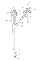
- FIG. 1 is an overall view showing a suture instrument according to an embodiment of the present invention. It is a schematic diagram which shows a suture needle. It is a top view which shows the treatment part in the suture instrument. It is a top view which shows the structure of a part of the treatment part. It is explanatory drawing for demonstrating operation
- FIG. 3B is a cross-sectional view taken along line AA in FIG. 3A.
- FIG. 4B is a cross-sectional view showing a state where the suture needle and the needle fixing portion are not attached in FIG. 4A. It is a perspective view which shows a link member. It is a front view of a treatment part.
- FIG. 8 is a reference diagram for comparison with the configuration shown in FIG. 7. It is explanatory drawing which shows one process at the time of use of the suturing device. It is explanatory drawing which shows one process at the time of use of the suturing device. It is a schematic diagram for demonstrating the effect
- FIG. 1 is an overall view showing a suturing device according to an embodiment of the present invention.
- the suturing device 1 is an apparatus that is used together with an endoscope 100 and sutures a living tissue using a suture thread 6.
- the suturing device 1 includes a suturing needle 2 to which a suture thread 6 is attached and an applicator 10 for puncturing the suturing needle 2 into a living tissue.
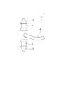
- FIG. 2 is a schematic diagram showing a suture needle.
- the suture needle 2 is a needle having one end (first end) formed in a cone shape and the other end (second end) formed sharply.
- the end part (first end part) 3 (second end part) 4 of the suture needle 2 is formed conically and sharply. That is, the end portions 3 and 4 of the suture needle 2 can puncture a living tissue.
- two groove portions 5 that are engaged with a pair of needle fixing portions 30 described later are formed between the end portions 3 and 4 of the suture needle 2, two groove portions 5 that are engaged with a pair of needle fixing portions 30 described later are formed.
- Each groove 5 has an outer diameter smaller than the maximum outer diameter of the conical portion at the end of the suture needle 2.
- an end portion of the suture thread 6 is fixed between the groove portions 5 in the intermediate portion of the suture needle 2.
- the applicator 10 includes a treatment section 11, a long shaft member 50 in which the treatment section 11 is arranged at one end (first end), and the other end (second end) of the long shaft member 50.
- the operation unit 60 is provided.
- the side on which the treatment unit 11 is disposed will be described as the distal end side
- the side on which the operation unit 60 is disposed will be described as the proximal end side.
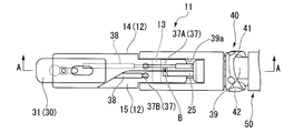
- FIG. 3A is a plan view showing the treatment portion 11 in the suture instrument 1.
- FIG. 3B is a plan view showing a partial configuration of the treatment section 11.
- FIG. 3C is a view for explaining the operation of the treatment portion 11 in the suture instrument 1.
- 4A is a cross-sectional view taken along line AA in FIG. 3A.
- 4B is a cross-sectional view showing a state in which the suture needle 2 and the needle fixing portion 30 are removed in FIG. 4A.
- the treatment section 11 includes a pair of gripping members 12, a pair of needle fixing sections 30 provided on the pair of gripping members 12, and a pair of gripping members 12 as long axes.
- the cover member 39 connected to the member 50 and the link member 40 connected to the long shaft member 50 are provided.
- the pair of gripping members 12 includes a first gripping member 14 and a second gripping member 15 that are connected to each other by a pin 13 at a proximal end portion so as to be relatively rotatable.
- the first gripping member 14 and the second gripping member 15 are relatively rotated with the central axis of the pin 13 as the center of rotation. Thereby, a pair of holding member 12 opens and closes.
- the first gripping member 14 is formed with a first gripping surface 17 for gripping the living tissue
- the second gripping member 15 is formed with a second gripping surface 18 for gripping the living tissue.
- a recess 19 is formed in the first gripping surface 17 so as to be recessed in a direction perpendicular to the first gripping surface 17.
- a recess 20 is formed in the second gripping surface 18 so as to be recessed in a direction orthogonal to the second gripping surface 18.
- the depressions 19 and 20 formed in the first gripping surface 17 and the second gripping surface 18 have shapes that follow the shapes of the end portions 3 and 4 of the suture needle 2.
- the end portions 3 and 4 of the suture needle 2 are fitted in the recesses 19 and 20.
- a link 25 is connected to the base ends of the pair of gripping members 12. Further, an opening / closing wire 26 (power transmission member) is fixed to the link 25.
- the link 25 is provided to convert the advance / retreat operation of the opening / closing wire 26 into the opening / closing operation of the pair of gripping members 12.
- the open / close wire 26 has a distal end connected to the pair of gripping members 12 via the link 25, and a proximal end connected to the operation unit 60 (see FIG. 1).
- the opening / closing wire 26 is a wire rod (for example, a stranded wire) fixed to the proximal end of the link 25, and is inserted through the coil sheath 52 (see FIG. 7) inside the long shaft member 50.
- the pair of needle fixing portions 30 are arranged inside each of the pair of gripping members 12.
- the pair of gripping members 12 are provided with grooves 21 and 22 into which the needle fixing portion 30 is inserted, and lids 23 and 24 that respectively close the grooves 21 and 22.
- the grooves 21 and 22 are formed so as to extend from the distal ends of the pair of gripping members 12 toward the proximal end, and the distal ends of the grooves 21 and 22 are opened.
- a needle fixing first member 31 which is a plate-like member constituting the pair of needle fixing portions 30, is inserted into the groove 21.
- the needle fixing first member 31 is formed with a through hole 33 penetrating in the plate thickness direction and a locking hole portion 35 formed so as to be connected to the through hole 33.
- the through hole 33 has an inner diameter that is substantially the same as the inner diameter of the recess 19 (see FIGS. 4A and 4B) formed in the pair of gripping members 12.
- One of the end portions 3 and 4 of the suture needle 2 can be inserted into the through-hole 33.
- the width of the locking hole portion 35 is smaller than the inner diameter of the through hole 33 and larger than the outer diameter of the groove portion 5 formed in the suture needle 2. Further, the locking hole portion 35 is disposed on the proximal end side of the through hole 33. Thereby, when the locking hole 35 enters the groove 5 of the suture needle 2, one of the end portions 3 and 4 of the suture needle 2 is fixed to the needle fixing first member 31.
- a needle fixing second member 32 which is a plate-like member constituting the pair of needle fixing portions 30, is inserted into the groove 22.
- the needle fixing second member 32 is formed with a through hole 34 similar to the above-described through hole 33 and a locking hole portion 36 similar to the above-described locking hole portion 35.
- the needle fixing second member 32 is formed in the same shape and size as the needle fixing first member 31. The shape of the needle fixing second member 32 and the needle fixing first member 31 may be different from each other.
- a delivery wire 37 (linear member) is fixed to the proximal ends of the pair of needle fixing portions 30. That is, the distal end of the first delivery wire 37 ⁇ / b> A (first linear member) is fixed to the proximal end of the needle fixing first member 31, and the delivery first wire 37 ⁇ / b> A (first linear member) is attached to the proximal end of the needle fixing second member 32. The tip of the two wires 37B (second linear member) is fixed. The delivery wire 37 is disposed at a position separated from the link 25 so as to avoid the link 25.
- the delivery wire 37 In the delivery wire 37, a range from the pin 13 that is an opening and closing shaft of the pair of gripping members 12 to the tip of the delivery wire 37 is covered with a hard pipe 38.
- the delivery wire 37 has flexibility in a portion B (see FIGS. 3A, 3B, and 3C) that is curved by opening and closing operations of the pair of gripping members 12 (see FIG. 3A), and the curved portion B is bent.
- it has high rigidity that is less likely to buckle on the tip side.
- the pipe 38 that covers the delivery wire 37 may be made of a material harder than the delivery wire 37 or may be a pipe having the same hardness as the delivery wire 37. That is, the pipe 38 that covers the delivery wire 37 only needs to reinforce the delivery wire 37.
- the cover member 39 is a cylindrical member fixed to the tip of the long shaft member 50.
- the cover member 39 holds both ends of the pin 13.
- a link 25 and an opening / closing wire 26 for opening and closing the pair of gripping members 12 are inserted inside the cover member 39.
- a slit 39 a is formed on the outer peripheral surface of the cover member 39 to prevent the pair of gripping members 12 and the link 25 from interfering with the cover member 39 when the pair of gripping members 12 are opened and closed.
- FIG. 5 is a perspective view showing the link member 40.
- the link member 40 includes an annular main body 41, rotation support portions 42 and 43, and a pair of connection portions 44 and 45.
- the main body 41 rotates relative to the cover member 39 with the central axis of the rotation support portions 42 and 43 as the rotation center.
- An opening / closing wire 26 and a delivery wire 37 are inserted inside the annular body 41.
- the rotation support portions 42 and 43 are formed in a columnar shape having a central axis extending in a direction intersecting the longitudinal axis of the long shaft member 50.
- the shape of the rotation support parts 42 and 43 is not limited to a cylindrical shape, and may be other than a cylindrical shape.
- the rotation support portions 42 and 43 are provided for the purpose of connecting the main body 41 to the cover member 39.
- the rotation support portions 42 and 43 have the center axis X directed in a direction orthogonal to the longitudinal axis of the long shaft member 50.
- the rotation support parts 42 and 43 are arrange
- the rotation support portions 42 and 43 are fixed to the main body 41. Furthermore, the ends 42a and 43a facing the inside of the main body 41 in the rotation support portions 42 and 43 are inserted into the cover member 39 (see FIG. 3A). Accordingly, as shown in FIG. 3A, the main body 41 is connected to the cover member 39 by the rotation support portions 42 and 43. That is, in the present embodiment, the rotation support portions 42 and 43 connect the link member 40 and the long shaft member 50 via the cover member 39.
- the connecting portions 44 and 45 are two rod-like members extending in parallel with each other, and the delivery wire 37 is inserted through the main body 41.
- the rod-shaped members constituting the connecting portions 44 and 45 are rotatable relative to the main body 41 with the central axes X ′ and X ′′ as the rotation centers.
- each rod-shaped member At the center in the central axis direction of each rod-shaped member, holes 44a and 45a extending in the direction perpendicular to the central axis are formed.
- Two delivery wires 37 (a delivery first wire 37A and a delivery second wire 37B) are respectively inserted into the holes 44a and 45a formed in the respective rod-shaped members constituting the connecting portions 44 and 45. .
- the connecting portions 44 and 45 can connect the delivery wire 37 to the longitudinal axis of the long shaft member 50 regardless of the rotating angle of the main body 41 itself. Maintain approximately parallel to the axis.
- the connecting portions 44 and 45 do not have to be rod-like members, and the same effect can be obtained as long as the connecting portions 44 and 45 are rotatable relative to the main body 41.
- a cylindrical member 46 is fixed to the delivery wire 37 ⁇ / b> A inserted through the holes 44 a and 45 a of the coupling portions 44 and 45.
- the delivery second wire 37 ⁇ / b> B is also provided with the same configuration as the cylindrical member 46.
- a delivery wire 37 is inserted into the cylindrical member 46. Further, the cylindrical member 46 abuts on the opening end of the hole 44 a formed in the connecting portion 44. The delivery wire 37 is positioned with respect to the connecting portion 44 by the cylindrical member 46 coming into contact with the opening end of the connecting portion 44. The cylindrical member 46 a disposed on the distal end side of the connecting portion 44 in the cylindrical member 46 is attached to the delivery wire 37 by a fixing method having a strength capable of withstanding the traction force when the delivery wire 37 is pulled to the proximal end side. It is fixed.
- cylindrical member 46b disposed on the proximal end side of the connecting portion 44 in the cylindrical member 46 has a strength that can withstand the pressing force when the delivery wire 37 is pressed to the distal end side by the connecting portion 44. It is fixed to the delivery wire 37 by a method.
- the frictional resistance generated in the transfer wire 37 on the proximal side from the link member 40 is larger than the frictional resistance generated in the transfer wire 37 on the distal side from the link member 40.
- the cylindrical member 46a disposed on the distal end side of the connecting portions 44 and 45 has a fixing method having higher strength than the cylindrical member 46b disposed on the proximal end side of the connecting portions 44 and 45. It has been adopted.
- the cylindrical member 46 a disposed on the distal end side of the connecting portions 44 and 45 is fixed to the delivery wire 37 by laser welding.
- the cylindrical member 46 b disposed on the base end side of the connecting portions 44 and 45 is fixed to the delivery wire 37 by brazing or the like. Note that the fixing method of each cylindrical member 46 to the delivery wire 37 may be a different fixing method in consideration of workability.
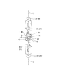
- FIG. 6 is a front view of the treatment section.
- the link member 40 in order to emphasize the positional relationship of the link member 40, the link member 40 hidden behind the pair of gripping members 12, the cover member 39, etc. is intentionally shown.
- the link member 40 has a positional relationship in which the entire link member 40 is displaced in the circumferential direction with respect to the midline L of the pair of gripping members 12.
- the transfer wire 37 is parallel to the longitudinal axis of the long shaft member 50 in the region from the pair of gripping members 12 to the holes 44a and 45a of the connecting portions 44 and 45. It becomes a straight line state.
- FIG. 7 is a cross-sectional view showing a cross section perpendicular to the longitudinal axis of the long shaft member.
- the long shaft member 50 includes a resin outer sheath 51 and a coil sheath 52 inserted through the outer sheath 51.
- the outer sheath 51 and the coil sheath 52 constituting the long axis member 50 are flexible members having a longitudinal axis.
- the outer sheath 51 is a cylindrical member having an outer diameter that can be inserted into a treatment instrument channel (indicated by reference numeral 101 in FIG. 1) of an endoscope.
- the outer surface of the outer sheath 51 is a surface state with low frictional resistance against the inner surface of the treatment instrument channel 101.
- the coil sheath 52 is a sheath in which a wire is wound in a coil shape with the longitudinal axis of the long shaft member 50 as the center, and is a sheath that balances flexibility and resistance to compression in the longitudinal axis direction.
- An opening / closing wire 26 is inserted into the coil sheath 52.
- the outer sheath 51 and the coil sheath 52 are in a state where their centerlines are shifted in parallel.
- second coil sheaths 53 and 54 are disposed between the outer sheath 51 and the coil sheath 52.
- the second coil sheaths 53 and 54 are cylindrical members through which the delivery wire 37 is inserted.
- the second coil sheaths 53 and 54 are disposed adjacent to each other inside the long shaft member 50. Accordingly, the maximum outer diameter of the bundle of the coil sheath 52 and the second coil sheaths 53 and 54 is reduced as compared with the case where the second coil sheaths 53 and 54 are arranged at positions facing the radial direction of the coil sheath 52. Can do.
- the thickness d2 of the outer sheath 51a in the case where the second coil sheaths 53 and 54 are arranged at positions facing each other with the coil sheath 52 interposed therebetween is shown in FIG.
- the thickness d1 of the outer sheath 51 can be increased without increasing the outer diameter of the outer sheath 51. For this reason, it is possible to achieve both reduction in the diameter of the long shaft member 50 and prevention of buckling of the long shaft member 50.
- the opening ends on the distal end side of the second coil sheaths 53 and 54 are arranged at positions spaced from the link member 40 toward the proximal end side.
- the transfer wire 37 extending from the opening end on the distal end side of the second coil sheaths 53 and 54 is passed to the holes 44a and 45a formed in the connecting portions 44 and 45 provided in the link member 40 (see FIGS. 4A and 4B). Each of them extends.
- the operation unit 60 includes a first slider 61 for pushing and pulling the opening / closing wire 26, and second sliders 62 and 63 for pulling each of the delivery wires 37.
- the base end of the opening / closing wire 26 is fixed to the first slider 61.
- the second slider 62 is a slider for pulling the delivery first wire 37A.
- the second slider 63 is a slider for pulling the delivery second wire 37B.
- the base ends of the transfer wires 37 are fixed to the second sliders 62 and 63.
- the operation unit 60 is an open / close operation unit that performs an operation of transmitting power to the open / close wire 26 in order to open / close the pair of gripping members 12, and the transfer wire 37 is connected to the long shaft member 50.
- This is a needle fixing operation unit that performs an operation of moving the needle 2 along the longitudinal axis of the needle 2 to fix and release the suture needle 2 from the needle fixing unit 30.
- the configuration of the operation unit 60 is not limited to the configuration having the first slider 61 and the second sliders 62 and 63.
- the operation unit 60 employs a configuration in which the opening / closing wire 26 or the delivery wire 37 is moved using a lever, a configuration in which the opening / closing wire 26 or the delivery wire 37 is wound around a rotating shaft, and the like. It may be.
- FIG. 9 and FIG. 10 are explanatory views showing one process when the suturing device 1 is used.
- FIG. 11 is a schematic diagram for explaining the operation of the suturing device 1.
- the suturing device 1 is prepared in a state where the suturing needle 2 is attached to one of the pair of gripping members 12 provided in the suturing device 1 (second gripping member 15 in FIG. 9).
- the suturing device 1 is inserted into the treatment instrument channel 101 of the endoscope 100 from the treatment unit 11 side and guided to a target site that is a target for suturing a living tissue.
- the first slider 61 shown in FIG. 1 is pulled to close the pair of gripping members 12 to the site T to be sutured as shown in FIG. Grasp the living tissue located.
- the suturing needle 2 attached to one of the pair of gripping members 12 is the gripping surface of the other of the pair of gripping members 12 (first gripping member 14) ( It enters into the depression (indentation 19) formed in the first gripping surface 17).
- the suture needle 2 is punctured into the living tissue Ta between the gripping surfaces 17 and 18 arranged to face each other in the pair of gripping members 12.
- the suturing device 1 of the present embodiment when the traction force of the first slider 61 shown in FIG. 1 is loosened, the grasping of the living tissue between the first grasping surface 17 and the second grasping surface 18 is released.
- the first slider 61 is moved to the tip side, the pair of gripping members 12 are opened.
- the suture needle 2 remains attached to the second gripping member 15.
- the suture needle 2 can be re-stabbed into the living tissue.
- the living tissue is moved in the same manner as a grasping forceps that merely grasps the living tissue. Or change the direction of the living tissue.
- the connecting portion 45 of the link member 40 is moved to the proximal end side on the distal end side of the long shaft member 50. Since the link member 40 can be rotated with respect to the cover member 39 by the rotation support portions 42 and 43, when the connecting portion 45 is moved to the proximal end side, the connecting portion 44 is moved to the distal end side.
- the first wire for transfer 37A the portion on the distal end side with respect to the link member 40 is pressed toward the distal end side
- the first wire for transfer 37A the portion on the proximal end side with respect to the link member 40 is pulled toward the distal end side. . That is, the delivery first wire 37 ⁇ / b> A moves to the distal end side as a whole by the action of the link member 40.
- the needle fixing first member 31 to which the distal end of the delivery first wire 37A is secured is pressed by the delivery first wire 37A and moves to the distal end side. Then, the needle fixing first member 31 moves so that the locking hole portion 35 enters the groove portion 5. As a result, the suture needle 2 is fixed to the needle fixing first member 31.
- the needle fixing second member 32 to which the distal end of the delivery second wire 37B is secured moves to the proximal end side when the delivery second wire 37B is pulled. Then, the needle fixing second member 32 moves so that the locking hole portion 36 is disengaged from the groove portion 5. Thereby, the suture needle 2 can be detached from the needle fixing second member 32.
- the first wire for delivery 37A is positioned closer to the first gripping member 14 than the pin 13, and the second wire for delivery 37B is closer to the first than the pin 13. It is located on the two gripping member 15 side. Accordingly, when the pair of gripping members 12 is opened, the pair of needle fixing portions 30 is pressed so that the pair of needle fixing portions 30 are relatively advanced with respect to the pair of gripping members 12. As a result, the locking hole portion of the needle fixing first member 31 or the needle fixing second member 32 enters the groove portion 5 formed in the suturing needle 2, and the suturing needle 2 is moved by a slight forward and backward movement of the second sliders 62 and 63. Do not fall off.
- the suture thread 6 is ligated as necessary, and a series of treatments is completed.
- the suture thread 6 may be inserted through the living tissue again.
- the pair of gripping members 12 are closed, and the delivery second wire 37 ⁇ / b> B is moved to the proximal end side in the operation unit 60.
- the suture needle 2 can be detached from the needle fixing second member 32 provided on the second gripping member 15, and at the same time, the suture needle 2 can be removed by the needle fixing first member 31 provided on the first gripping member 14. It is fixed to one gripping member 14.
- the suturing device 1 can grasp a tissue to sew a living tissue and deliver the suturing needle 2 between a pair of grasping members 12, and can also hold the suturing needle 2 after grasping the living tissue once.
- the gripping member 12 can be opened again without delivery.
- grips a biological tissue and the function as an apparatus which sutures a biological tissue can be reconciled.
- the suturing device 1 can be used by inserting the suturing device 1 into the treatment instrument channel of the flexible endoscope, it is necessary to suture the living tissue when performing a diagnosis using the flexible endoscope. When a special site is found, the treatment tool of the suture instrument 1 can be easily guided to the suture target site.
- an endoscope provided with only one treatment instrument channel, it is possible to move a living tissue in the vicinity of a suture target site or suture a suture target site without separately preparing a grasping forceps. .
- the suturing position can be easily changed after once grasping the living tissue.
- the above embodiment can be suitably applied to a suturing device that sutures biological tissue.
Landscapes
- Health & Medical Sciences (AREA)
- Life Sciences & Earth Sciences (AREA)
- Surgery (AREA)
- Heart & Thoracic Surgery (AREA)
- Engineering & Computer Science (AREA)
- Biomedical Technology (AREA)
- Nuclear Medicine, Radiotherapy & Molecular Imaging (AREA)
- Medical Informatics (AREA)
- Molecular Biology (AREA)
- Animal Behavior & Ethology (AREA)
- General Health & Medical Sciences (AREA)
- Public Health (AREA)
- Veterinary Medicine (AREA)
- Surgical Instruments (AREA)
- Sewing Machines And Sewing (AREA)
Abstract
縫合器は、長軸部材と、一対の把持部材と、縫合針と、動力伝達部材と、開閉操作部と、針固定第一部材と、針固定第二部材とを有し、縫合針を前記一対の把持部材に固定するまたは固定を解除する一対の針固定部と、前記一対の針固定部に連結された一対の線状部材と、前記一対の線状部材を操作する針固定操作部と、前記一対の線状部材に第一端及び第二端が固定されたリンク部材と、前記リンク部材を回動自在に支持する回動支持部と、を備える。
Description
本発明は、医療用の縫合器に関する。
本願は、2012年08月24日に、米国に仮出願された米国特許出願第61/693,028号に基づき優先権を主張し、その内容をここに援用する。
本願は、2012年08月24日に、米国に仮出願された米国特許出願第61/693,028号に基づき優先権を主張し、その内容をここに援用する。
従来、体内で縫合をするための縫合器が知られている。例えば日本国特表2001-500765号公報には、自動針受け渡し縫合器が開示されている。
日本国特表2001-500765号公報に開示された縫合器は、2つのエンドエフェクタと、これらのエンドエフェクタに係合する針とを有している。この縫合器では、2つのエンドエフェクタのうちの一方のエンドエフェクタから他方のエンドエフェクタへ、針を受け渡すことにより、生体組織に針を通して縫合することができる。
日本国特表2001-500765号公報に開示された縫合器は、2つのエンドエフェクタと、これらのエンドエフェクタに係合する針とを有している。この縫合器では、2つのエンドエフェクタのうちの一方のエンドエフェクタから他方のエンドエフェクタへ、針を受け渡すことにより、生体組織に針を通して縫合することができる。
従来、一対の把持部材間で縫合針を受け渡しする縫合器は、把持部材の開閉と縫合針の受け渡しとが連動しており、一対の把持部材を一度閉じると縫合針は自動的に反対側の把持部材へと受け渡される。このため、把持部材を閉じて生体組織を把持し、生体組織をつかみなおすことはできない。また、処置具を挿通可能な1つあるいは複数の処置具チャンネルを備えた軟性内視鏡が知られているが、処置具チャンネルの数が多すぎると挿入部の外径が太くなり作業性が悪くなる。このため、限られた数の処置具チャンネルを有効利用できることが望まれている。
本発明は、上記の様な問題に鑑みてなされたものであり、生体組織を縫合するために組織を把持して一対の把持部材間で縫合針を受け渡すことができるとともに、一度生体組織を把持した後に縫合針を受け渡すことなく再度把持部材を開くこともできる縫合器の提供を目的とする。
本発明は、上記の様な問題に鑑みてなされたものであり、生体組織を縫合するために組織を把持して一対の把持部材間で縫合針を受け渡すことができるとともに、一度生体組織を把持した後に縫合針を受け渡すことなく再度把持部材を開くこともできる縫合器の提供を目的とする。
本発明の第1の態様に係る縫合器は、長手軸に沿って延設された長軸部材と、 前記長軸部材の先端に設けられ、対象部位を処置するために開閉動作可能な第一把持部材と第二把持部材とを有する一対の把持部材と、前記一対の把持部材の間で組織を穿刺するために、前記一対の把持部材と係合する縫合針と、前記一対の把持部材が開閉するための動力を前記一対の把持部材に伝達するために、先端部が前記一対の把持部材に連結され、前記長手軸に沿って延設された動力伝達部材と、前記動力が前記動力伝達部材に生じるように前記動力伝達部材を操作する開閉操作部と、前記第一把持部材に対して移動可能に設けられた針固定第一部材と、前記第二把持部材に対して移動可能に設けられた針固定第二部材とを有し、前記一対の把持部材に対する自身の移動に応じて前記縫合針を前記一対の把持部材に固定するまたは固定を解除する一対の針固定部と、前記一対の針固定部をそれぞれ前記一対の把持部材に対して相対的に移動させるために、前記針固定第一部材に連結された第一線状部材と、前記第針固定第二部材に連結された第二線状部材とを有し、前記長手軸に沿って前記動力伝達部材に対して移動自在に配置された一対の線状部材と、前記一対の線状部材の基端部に設けられ、前記一対の線状部材を前記長手軸に沿って移動するように操作する針固定操作部と、前記長軸部材の先端部に設けられ、前記第一線状部材に第一端が固定され、且つ前記第二線状部材に第二端が固定されたリンク部材と、前記針固定操作部の操作によって前記第一線状部材を前記基端部側に牽引したときに、前記第二線状部材が前記一対の把持部材側に前進するように、前記第一線状部材と前記第二線状部材との間において、前記長手軸と交差する軸方向に延びた回動軸周りに前記リンク部材を回動自在に支持する回動支持部と、を備える。
本発明の第2の態様に係る縫合器は、上記第1の態様において、前記針固定操作部による前記第一線状部材を牽引する動作に応じて、前記リンク部材が前記回動軸周りに回動されると共に、前記第二線状部材が前記一対の把持部材側に移動されることによって、前記針固定第一部材に前記縫合針が固定されると共に、前記針固定第二部材への前記縫合針の固定が解除される。
本発明の第3の態様に係る縫合器は、上記第2の態様において、前記リンク部材は、前記長手軸周りの周方向に沿った湾曲形状である。
本発明の第4の態様に係る縫合器は、上記第1の態様において、前記リンク部材は、前記長手軸方向に開口し、前記回動軸を有する環状の本体と、前記回動軸の回動中心と平行な軸線を回動中心として前記本体に対して回動可能に前記本体に連結され、前記線状部材が挿通される貫通孔が形成された連結部と、を有し、前記線状部材には、前記貫通孔の開口端部に当接し、前記線状部材を前記連結部に対して位置決めするための筒部材が取り付けられている。
本発明の第5の態様に係る縫合器は、上記第1の態様において、前記線状部材は可撓性を有し、前記線状部材は、前記長手軸方向における前記一対の把持部材の開閉軸と前記線状部材の先端との間において、硬質なパイプに挿通され、前記パイプに固定されている。
本発明の第6の態様に係る縫合器は、上記第1の態様において、前記把持部材は、前記縫合針を支えるための錐体状の窪みを有し、前記縫合針は、前記窪みに嵌合する錐体状の端部と、前記端部と隣接し前記端部よりも小さい径を有する溝部と、を有し、前記針固定部は、前記端部が挿通可能な貫通孔と、前記貫通孔とつながって形成され、前記貫通孔の内径よりも小さく且つ前記溝部の外径よりも大きい幅を有する係止孔部と、を有する。
上記本発明の各態様によれば、生体組織を縫合するために組織を把持して一対の把持部材間で縫合針を受け渡すことができるとともに、一度生体組織を把持した後に縫合針を受け渡すことなく再度把持部材を開くこともできる縫合器を提供できる。これにより、生体組織を把持する鉗子としての機能と、生体組織を縫合する装置としての機能を両立することができる。
本発明の一実施形態の縫合器について説明する。
図1は、本発明の一実施形態の縫合器を示す全体図である。図1に示すように、縫合器1は、内視鏡100とともに使用され、縫合糸6を用いて生体組織を縫合する装置である。縫合器1は、縫合糸6が取り付けられた縫合針2と、縫合針2を生体組織に穿刺するためのアプリケータ10とを備える。
図1は、本発明の一実施形態の縫合器を示す全体図である。図1に示すように、縫合器1は、内視鏡100とともに使用され、縫合糸6を用いて生体組織を縫合する装置である。縫合器1は、縫合糸6が取り付けられた縫合針2と、縫合針2を生体組織に穿刺するためのアプリケータ10とを備える。
図2は、縫合針を示す模式図である。図2に示すように、縫合針2は、一端(第一端)が錐体状に形成され、他端(第二端)が鋭利に形成された針である。本実施形態では、縫合針2の端部(第一端部)3,(第二端部)4は、円錐形且つ鋭利に形成されている。すなわち、縫合針2の端部3,4は、いずれも生体組織に穿刺できる。また、縫合針2の端部3,4の間には、後述する一対の針固定部30が係合する溝部5が2つ形成されている。各溝部5は、縫合針2の端部における円錐形部分の最大外径よりも小さな外径を有する。また、縫合針2の中間部であって各溝部5の間には、縫合糸6の端部が固定されている。
図1に示すように、アプリケータ10は、処置部11と、処置部11が一端(第一端)に配された長軸部材50と、長軸部材50の他端(第二端)に配された操作部60とを備える。以下、アプリケータ10において、処置部11が配された側を先端側、操作部60が配された側を基端側として説明する。
図3Aは、縫合器1における処置部11を示す平面図である。図3Bは、処置部11における一部の構成を示す平面図である。図3Cは、縫合器1における処置部11の動作を説明するための図である。図4Aは、図3AのA-A線における断面図である。図4Bは、図4Aにおいて縫合針2及び針固定部30を取り外した状態を示す断面図である。
図3A,図4A及び図4Bに示すように、処置部11は、一対の把持部材12と、一対の把持部材12に設けられた一対の針固定部30と、一対の把持部材12を長軸部材50と連結するカバー部材39と、長軸部材50に連結されたリンク部材40とを有している。
一対の把持部材12は、基端部においてピン13により相対回動可能に連結された第一把持部材14及び第二把持部材15を有している。第一把持部材14と第二把持部材15とは、ピン13の中心軸線を回動中心として相対的に回動する。これにより、一対の把持部材12は開閉動作する。
第一把持部材14には、生体組織を把持するための第一把持面17が形成され、第二把持部材15には、生体組織を把持するための第二把持面18が形成されている。第一把持面17には、縫合針2を支えるために、第一把持面17に対して直交する方向に窪んで形成された窪み19が形成されている。第二把持面18には、縫合針2を支えるために、第二把持面18に対して直交する方向に窪んで形成された窪み20が形成されている。
第一把持面17及び第二把持面18に形成された窪み19,20は、縫合針2の端部3,4の形状に倣った形状を有する。窪み19,20には、縫合針2の端部3,4が嵌合する。
一対の把持部材12の各々の基端には、リンク25が連結されている。さらに、リンク25には、開閉用ワイヤ26(動力伝達部材)が固定されている。
リンク25は、開閉用ワイヤ26の進退動作を一対の把持部材12の開閉動作に変換するために設けられている。開閉用ワイヤ26は、先端がリンク25を介して一対の把持部材12と連結されており、基端が操作部60(図1参照)に接続されている。開閉用ワイヤ26は、リンク25の基端に固定された線材(例えば、より線)であり、長軸部材50の内部においてコイルシース52(図7参照)に挿通されている。
リンク25は、開閉用ワイヤ26の進退動作を一対の把持部材12の開閉動作に変換するために設けられている。開閉用ワイヤ26は、先端がリンク25を介して一対の把持部材12と連結されており、基端が操作部60(図1参照)に接続されている。開閉用ワイヤ26は、リンク25の基端に固定された線材(例えば、より線)であり、長軸部材50の内部においてコイルシース52(図7参照)に挿通されている。
図4A及び図4Bに示すように、一対の針固定部30は、一対の把持部材12の各々の内部に配されている。具体的には、一対の把持部材12には、針固定部30が挿入される溝21,22と、溝21,22の各々を塞ぐ蓋23,24とが設けられている。
溝21,22は、一対の把持部材12の先端から基端へ向かって延びて形成されており、溝21,22の先端は開口されている。
図4A及び図4Bに示すように、溝21には、一対の針固定部30を構成する板状の部材である針固定第一部材31が挿入されている。
溝21,22は、一対の把持部材12の先端から基端へ向かって延びて形成されており、溝21,22の先端は開口されている。
図4A及び図4Bに示すように、溝21には、一対の針固定部30を構成する板状の部材である針固定第一部材31が挿入されている。
図3Bに示すように、針固定第一部材31には、板厚方向に貫通された貫通孔33と、貫通孔33とつながって形成された係止孔部35とが形成されている。
貫通孔33は、一対の把持部材12に形成された窪み19(図4A及び図4B参照)の内径と略同じ大きさの内径を有する。貫通孔33には、縫合針2の端部3,4のうちの一方が挿通可能である。
貫通孔33は、一対の把持部材12に形成された窪み19(図4A及び図4B参照)の内径と略同じ大きさの内径を有する。貫通孔33には、縫合針2の端部3,4のうちの一方が挿通可能である。
係止孔部35の幅は、貫通孔33の内径よりも小さく、縫合針2に形成された溝部5の外径よりも大きい。また、係止孔部35は、貫通孔33の基端側に配置されている。これにより、縫合針2の溝部5に係止孔部35が入り込むと、縫合針2の端部3,4のうちの一方は針固定第一部材31に固定される。
図4A及び図4Bに示すように、溝22には、一対の針固定部30を構成する板状の部材である針固定第二部材32が挿入されている。針固定第二部材32には、上述の貫通孔33と同様の貫通孔34と、上述の係止孔部35と同様の係止孔部36とが形成されている。本実施形態では、針固定第二部材32は、針固定第一部材31と同形同大に形成されている。針固定第二部材32と針固定第一部材31との形状が互いに異なっていてもよい。
また、図3Bに示すように、一対の針固定部30の基端には、受け渡し用ワイヤ37(線状部材)の先端が固定されている。すなわち、針固定第一部材31の基端には、受け渡し用第一ワイヤ37A(第一線状部材)の先端が固定されており、針固定第二部材32の基端には、受け渡し用第二ワイヤ37B(第二線状部材)の先端が固定されている。受け渡し用ワイヤ37は、リンク25をよけるように、リンク25から離間した位置に配置されている。
受け渡し用ワイヤ37において、一対の把持部材12を連結し一対の把持部材12における開閉軸であるピン13から受け渡し用ワイヤ37の先端までの範囲は、硬質なパイプ38によって被覆されている。これにより、受け渡し用ワイヤ37は、一対の把持部材12(図3A参照)の開閉動作により湾曲する部分B(図3A,図3B,図3C参照)においては柔軟性を有し、湾曲する部分Bよりも先端側においては座屈しにくい高い剛性を有する。受け渡し用ワイヤ37を被覆するパイプ38は、受け渡し用ワイヤ37よりも硬質な材料であってもよいし、受け渡し用ワイヤ37と同等の硬度を有するパイプであってもよい。すなわち、受け渡し用ワイヤ37を被覆するパイプ38は、受け渡し用ワイヤ37を補強できればよい。
カバー部材39は、長軸部材50の先端に固定された筒状部材である。カバー部材39は、ピン13の両端を保持する。カバー部材39の内部には、一対の把持部材12を開閉させるリンク25及び開閉用ワイヤ26が挿通されている。カバー部材39の外周面には、一対の把持部材12の開閉動作時に一対の把持部材12およびリンク25がカバー部材39に干渉しないようにするためのスリット39aが形成されている。
図5は、リンク部材40を示す斜視図である。図5に示すように、リンク部材40は、環状の本体41と、回動支持部42,43と、一対の連結部44,45とを有する。
図3A,図4A及び図4Bに示すように、本体41は、回動支持部42,43の中心軸線を回動中心としてカバー部材39に対して回動する。環状に形成された本体41の内側には、開閉用ワイヤ26及び受け渡し用ワイヤ37が挿通されている。
図3A,図4A及び図4Bに示すように、本体41は、回動支持部42,43の中心軸線を回動中心としてカバー部材39に対して回動する。環状に形成された本体41の内側には、開閉用ワイヤ26及び受け渡し用ワイヤ37が挿通されている。
図5に示すように、回動支持部42,43は、長軸部材50の長手軸に対して交差する方向に中心軸線が延びている円柱状に形成されている。なお、回動支持部42,43の形状は円柱状に限らず、円柱状以外でもよい。回動支持部42,43は、本体41をカバー部材39に連結する目的で設けられている。本実施形態では、回動支持部42,43は、長軸部材50の長手軸に対して直交する方向に中心軸線Xが向けられている。また、回動支持部42,43は、環状の本体41の中心を間に挟んで対向する二箇所に配置されている。
回動支持部42,43は、本体41に固定されている。さらに、回動支持部42,43において本体41の内側に向けられた端42a、43aは、カバー部材39(図3A参照)に差し込まれる。これにより、図3Aに示すように、本体41は、回動支持部42,43によって、カバー部材39に連結されている。すなわち、本実施形態では、回動支持部42,43は、カバー部材39を介してリンク部材40と長軸部材50とを連結する。
図5に示すように、連結部44,45は、互いに平行に延びる2本の棒状部材であり、本体41に受け渡し用ワイヤ37が挿通される。連結部44,45を構成する各棒状部材は、各々の中心軸線X’,X’’を回動中心として本体41に対して相対的に回動自在である。
各棒状部材の中心軸線方向における中央に、この中心軸線と直交する方向に中心線が延びる孔44a,45aが形成されている。連結部44,45を構成する各棒状部材に形成された孔44a,45aには、2本の受け渡し用ワイヤ37(受け渡し用第一ワイヤ37A、受け渡し用第二ワイヤ37B)がそれぞれ挿通されている。
本体41と連結部44,45とが相対的に回動することができるため、連結部44,45は、本体41自身の回動角度に関係なく、受け渡し用ワイヤ37を長軸部材50の長手軸に対して略平行に維持する。
連結部44,45は、棒状部材でなくてもよく、本体41に対して相対的に回動自在であれば同じ効果が得られる。
連結部44,45は、棒状部材でなくてもよく、本体41に対して相対的に回動自在であれば同じ効果が得られる。
図4A,4Bに示すように、連結部44,45の孔44a,45aに挿通された受け渡し用ワイヤ37Aには、筒部材46が固定されている。なお、図示していないが、受け渡し用第二ワイヤ37Bにも筒部材46と同様の構成が設けられている。
筒部材46には、受け渡し用ワイヤ37が挿通される。さらに、筒部材46は、連結部44に形成された孔44aの開口端に当接する。筒部材46が連結部44の開口端に当接することにより、連結部44に対して受け渡し用ワイヤ37が位置決めされている。筒部材46において連結部44の先端側に配される筒部材46aは、受け渡し用ワイヤ37が基端側に牽引されたときの牽引力に耐えることができる強度を有する固定方法により受け渡し用ワイヤ37に固定されている。また、筒部材46において連結部44の基端側に配される筒部材46bは、受け渡し用ワイヤ37が先端側に連結部44により押圧されたときの押圧力に耐えることができる強度を有する固定方法により受け渡し用ワイヤ37に固定されている。
リンク部材40よりも基端側において受け渡し用ワイヤ37に生じる摩擦抵抗は、リンク部材40よりも先端側において受け渡し用ワイヤ37に生じる摩擦抵抗よりも大きい。特に、長軸部材50の長さが長くなると、長軸部材50内における受け渡し用ワイヤ37への摩擦抵抗が大きくなるので、摩擦抵抗の大きさの差が顕著となる。このため、本実施形態では、連結部44,45の先端側に配される筒部材46aは、連結部44,45の基端側に配される筒部材46bよりも高い強度を有する固定方法が採用されている。具体的には、本実施形態では、連結部44,45の先端側に配される筒部材46aは、受け渡し用ワイヤ37に対してレーザー溶接により固定されている。また、本実施形態では、連結部44,45の基端側に配される筒部材46bは、受け渡し用ワイヤ37に対してロウ付け等により固定されている。なお、受け渡し用ワイヤ37に対する各筒部材46の固定方法は、作業性を考慮して異なる固定方法でもよい。
図6は、処置部の正面図である。なお、図6においては、リンク部材40の位置関係を強調するために一対の把持部材12やカバー部材39等に隠れて本来見えないリンク部材40を敢えて示している。図6に示すように、本実施形態では、リンク部材40は、リンク部材40の全体が一対の把持部材12の正中線Lに対して周方向にずれた位置関係となっている。一対の把持部材12が全閉状態にあるときに、受け渡し用ワイヤ37は、一対の把持部材12から連結部44,45の孔44a,45aまでの領域において、長軸部材50の長手軸と平行な直線状態となる。
図7は、長軸部材の長手軸に直交する断面を示す断面図である。図7に示すように、長軸部材50は、樹脂製の外シース51と、外シース51に挿通されたコイルシース52とを有している。長軸部材50を構成する外シース51及びコイルシース52は、長手軸を有する柔軟な部材である。
外シース51は、内視鏡の処置具チャンネル(図1に符号101で示す。)に挿通可能な外径を有する筒状部材である。外シース51の外面は、処置具チャンネル101の内面に対する摩擦抵抗が低い表面状態である。
コイルシース52は、長軸部材50の長手軸を中心として線材がコイル状に巻かれたシースであり、柔軟性と、長手軸方向への圧縮に対する耐性とのバランスが取れたシースである。コイルシース52内には、開閉用ワイヤ26が挿通されている。
外シース51とコイルシース52とは、互いの中心線が平行にずれた状態にある。さらに、本実施形態では、外シース51とコイルシース52との間には、第二コイルシース53,54が配置されている。
外シース51とコイルシース52とは、互いの中心線が平行にずれた状態にある。さらに、本実施形態では、外シース51とコイルシース52との間には、第二コイルシース53,54が配置されている。
第二コイルシース53,54は、受け渡し用ワイヤ37が挿通される筒状部材である。第二コイルシース53,54は、長軸部材50の内部で互いに隣接して配置されている。これにより、第二コイルシース53,54がコイルシース52の径方向に対向する位置に配されている場合と比較して、コイルシース52と第二コイルシース53,54との束の最大外径を小さくすることができる。これにより、例えば図8に示すようにコイルシース52を間に挟んで対向する位置に第二コイルシース53,54が配されている場合の外シース51aの肉厚d2と比較して、図7に示すように、外シース51の外径を大きくすることなく外シース51の肉厚d1を厚くすることができる。このため、長軸部材50の細径化と、長軸部材50の座屈防止とを両立できる。
また、第二コイルシース53,54における先端側の開口端は、リンク部材40より基端側に離間した位置に配されている。第二コイルシース53,54の先端側の開口端から延びる受け渡し用ワイヤ37は、リンク部材40(図4A及び図4B参照)に設けられた各連結部44,45に形成された孔44a,45aへ向かってそれぞれ延びている。
図1に示すように、操作部60は、開閉用ワイヤ26を押し引きするための第一スライダ61と、受け渡し用ワイヤ37の各々を牽引するための第二スライダ62,63とを備える。第一スライダ61には開閉用ワイヤ26の基端が固定されている。第二スライダ62は、受け渡し用第一ワイヤ37Aを牽引するためのスライダである。第二スライダ63は、受け渡し用第二ワイヤ37Bを牽引するためのスライダである。第二スライダ62,63には、受け渡し用ワイヤ37の各々の基端が固定されている。
本実施形態では、操作部60は、一対の把持部材12を開閉動作させるために開閉用ワイヤ26に動力を伝達する操作をする開閉操作部であり、且つ、受け渡し用ワイヤ37を長軸部材50の長手軸に沿って移動させて縫合針2の針固定部30への固定及び固定解除を行う操作をする針固定操作部である。
操作部60の構成は、第一スライダ61や第二スライダ62,63を有する構成に限られない。例えば、操作部60は、レバーを用いて開閉用ワイヤ26あるいは受け渡し用ワイヤ37を移動させる構成や、回転する軸に開閉用ワイヤ26あるいは受け渡し用ワイヤ37を巻きつけて移動させる構成等が採用されていてもよい。
操作部60の構成は、第一スライダ61や第二スライダ62,63を有する構成に限られない。例えば、操作部60は、レバーを用いて開閉用ワイヤ26あるいは受け渡し用ワイヤ37を移動させる構成や、回転する軸に開閉用ワイヤ26あるいは受け渡し用ワイヤ37を巻きつけて移動させる構成等が採用されていてもよい。
次に、本実施形態の縫合器1の使用時の動作及び作用について説明する。図9及び図10は、縫合器1の使用時の一過程を示す説明図である。図11は、縫合器1の作用を説明するための模式図である。
縫合器1は、縫合器1に設けられた一対の把持部材12の一方(図9においては第二把持部材15)に、縫合針2を取り付けられた状態で用意される。縫合器1は、図1に示すように、処置部11側から内視鏡100の処置具チャンネル101内に挿入され、生体組織を縫合する対象である対象部位へと案内される。
縫合器1は、縫合器1に設けられた一対の把持部材12の一方(図9においては第二把持部材15)に、縫合針2を取り付けられた状態で用意される。縫合器1は、図1に示すように、処置部11側から内視鏡100の処置具チャンネル101内に挿入され、生体組織を縫合する対象である対象部位へと案内される。
縫合対象である部位Tまで処置部11が案内されたら、図1に示す第一スライダ61を牽引することにより、図10に示すように一対の把持部材12を閉じて縫合対象である部位Tに位置する生体組織を把持する。一対の把持部材12を閉じると、一対の把持部材12の一方(第二把持部材15)に取り付けられた縫合針2は、一対の把持部材12の他方(第一把持部材14)の把持面(第一把持面17)に形成された窪み(窪み19)に入り込む。これにより、一対の把持部材12において対向配置された把持面17,18の間にある生体組織Taに、縫合針2が穿刺される。
また、本実施形態の縫合器1では、図1に示す第一スライダ61の牽引力を緩めると、第一把持面17と第二把持面18との間にある生体組織の把持が解除される。また第一スライダ61を先端側へと移動させると、一対の把持部材12が開く。このとき、縫合針2は第二把持部材15に取り付けられた状態のままである。これにより、生体組織への縫合針2の刺し直しができる。なお、縫合針2が生体組織を貫通しない程度の力で第一スライダ61を牽引しつつ生体組織を把持することにより、生体組織を単に把持するだけの把持鉗子と同様に、生体組織を移動させたり生体組織の向きを変えたりすることもできる。
縫合糸6が取り付けられた縫合針2を用いて生体組織を縫合するためには、縫合針2が生体組織に穿刺された状態から、縫合針2が刺入された側からその反対側へと縫合針2を引き抜く。この場合、図1に示す操作部60において第二スライダ62,63として設けられた2つのスライダのうち、相対的に先端側にあるスライダを手作業等により牽引する。本実施形態では、受け渡し用第二ワイヤ37Bが固定された第二スライダ63が牽引される。
これにより、長軸部材50の先端側において、図11に示すように、リンク部材40の連結部45が基端側へと移動される。リンク部材40は回動支持部42,43によってカバー部材39に対して回動可能であるので、連結部45が基端側へ移動されると、連結部44は逆に先端側へと移動される。すなわち、受け渡し用第一ワイヤ37Aにおいてリンク部材40よりも先端側の部分は先端側へ押圧され、受け渡し用第一ワイヤ37Aにおいてリンク部材40よりも基端側の部分は先端側へと牽引される。すなわち、受け渡し用第一ワイヤ37Aは、リンク部材40の作用によって、全体として先端側へと移動する。
一対の把持部材12の内部では、受け渡し用第一ワイヤ37Aの先端が固定された針固定第一部材31は、受け渡し用第一ワイヤ37Aによって押圧されて先端側へ移動する。すると、係止孔部35が溝部5に入り込むように針固定第一部材31が移動する。これにより、針固定第一部材31に縫合針2が固定される。
また、受け渡し用第二ワイヤ37Bの先端が固定された針固定第二部材32は、受け渡し用第二ワイヤ37Bが牽引されることによって基端側へ移動する。すると、係止孔部36が溝部5から外れるように針固定第二部材32が移動する。これにより、針固定第二部材32から縫合針2が取り外しできる。
この状態で、第一スライダ61を先端側へ移動させることにより一対の把持部材12を開くと、縫合針2は、第一把持部材14に固定された状態で移動し、生体組織を貫通して引き抜かれる。その結果、縫合針2に固定された縫合糸6が生体組織に挿通される。
また、本実施形態では、処置部11を正面視したときに、受け渡し用第一ワイヤ37Aはピン13よりも第一把持部材14側に位置し、受け渡し用第二ワイヤ37Bはピン13よりも第二把持部材15側に位置している。これにより、一対の把持部材12を開いたときに、一対の把持部材12に対して一対の針固定部30が相対的に前進するように一対の針固定部30が押圧される。その結果、縫合針2に形成された溝部5に針固定第一部材31あるいは針固定第二部材32の係止孔部が入り込み、第二スライダ62,63の僅かな進退移動では縫合針2が脱落しない。
その後、必要に応じて縫合糸6を結紮し、一連の処置を終了する。なお、必要に応じて、第二把持部材15から第一把持部材14へと縫合針2を受け渡した後に生体組織に対して再度縫合糸6を挿通させてもよい。
要約すると、第二把持部材15から第一把持部材14へ針を受け渡す場合には、一対の把持部材12を閉じ、操作部60において受け渡し用第二ワイヤ37Bを基端側へと移動させる。これにより、第二把持部材15に設けられた針固定第二部材32から縫合針2が取り外し可能となり、同時に、第一把持部材14に設けられた針固定第一部材31によって縫合針2が第一把持部材14に固定される。
本実施形態の縫合器1は、生体組織を縫合するために組織を把持して一対の把持部材12間で縫合針2を受け渡すことができるとともに、一度生体組織を把持した後に縫合針2を受け渡すことなく再度把持部材12を開くこともできる。これにより、生体組織を把持する鉗子としての機能と、生体組織を縫合する装置としての機能を両立することができる。
また、軟性内視鏡の処置具チャンネル内に縫合器1を挿通して縫合器1を使用することができるので、軟性内視鏡を用いて診察をしている際に生体組織の縫合が必要な部位を発見した場合、縫合器1の処置具を容易に縫合対象部位まで案内することができる。
特に、処置具チャンネルが1つだけ設けられた内視鏡において、把持鉗子を別途用意することなく縫合対象部位近傍の生体組織を移動させたり縫合対象部位を縫合したりできるので、作業効率がよい。
また、一度生体組織を把持した後に縫合位置を容易に変更することができる。
また、軟性内視鏡の処置具チャンネル内に縫合器1を挿通して縫合器1を使用することができるので、軟性内視鏡を用いて診察をしている際に生体組織の縫合が必要な部位を発見した場合、縫合器1の処置具を容易に縫合対象部位まで案内することができる。
特に、処置具チャンネルが1つだけ設けられた内視鏡において、把持鉗子を別途用意することなく縫合対象部位近傍の生体組織を移動させたり縫合対象部位を縫合したりできるので、作業効率がよい。
また、一度生体組織を把持した後に縫合位置を容易に変更することができる。
以上、本発明の好ましい実施形態の一例について説明したが、本発明は上記実施形態に限定されることはない。本発明の趣旨を逸脱しない範囲で、構成の付加、省略、置換、およびその他の変更が可能である。
上記実施形態は、生体組織を縫合する縫合器に好適に適用することができる。
3,4 端部
5 溝部
12 把持部材
26 開閉用ワイヤ(動力伝達部材)
30 針固定部
33 貫通孔
35 係止孔部
37 受け渡し用ワイヤ(線状部材)
38 パイプ
40 リンク部材
41 本体
42,43 回動支持部
44,45 連結部
46 筒部材
50 長軸部材
60 操作部(開閉操作部,針固定操作部)
5 溝部
12 把持部材
26 開閉用ワイヤ(動力伝達部材)
30 針固定部
33 貫通孔
35 係止孔部
37 受け渡し用ワイヤ(線状部材)
38 パイプ
40 リンク部材
41 本体
42,43 回動支持部
44,45 連結部
46 筒部材
50 長軸部材
60 操作部(開閉操作部,針固定操作部)
Claims (6)
- 長手軸に沿って延設された長軸部材と、
前記長軸部材の先端に設けられ、対象部位を処置するために開閉動作可能な第一把持部材と第二把持部材とを有する一対の把持部材と、
前記一対の把持部材の間で組織を穿刺するために、前記一対の把持部材と係合する縫合針と、
前記一対の把持部材が開閉するための動力を前記一対の把持部材に伝達するために、先端部が前記一対の把持部材に連結され、前記長手軸に沿って延設された動力伝達部材と、
前記動力が前記動力伝達部材に生じるように前記動力伝達部材を操作する開閉操作部と、
前記第一把持部材に対して移動可能に設けられた針固定第一部材と、前記第二把持部材に対して移動可能に設けられた針固定第二部材とを有し、前記一対の把持部材に対する自身の移動に応じて前記縫合針を前記一対の把持部材に固定するまたは固定を解除する一対の針固定部と、
前記一対の針固定部をそれぞれ前記一対の把持部材に対して相対的に移動させるために、前記針固定第一部材に連結された第一線状部材と、前記第針固定第二部材に連結された第二線状部材とを有し、前記長手軸に沿って前記動力伝達部材に対して移動自在に配置された一対の線状部材と、
前記一対の線状部材の基端部に設けられ、前記一対の線状部材を前記長手軸に沿って移動するように操作する針固定操作部と、
前記長軸部材の先端部に設けられ、前記第一線状部材に第一端が固定され、且つ前記第二線状部材に第二端が固定されたリンク部材と、
前記針固定操作部の操作によって前記第一線状部材を前記基端部側に牽引したときに、前記第二線状部材が前記一対の把持部材側に前進するように、前記第一線状部材と前記第二線状部材との間において、前記長手軸と交差する軸方向に延びた回動軸周りに前記リンク部材を回動自在に支持する回動支持部と、
を備える縫合器。 - 前記針固定操作部による前記第一線状部材を牽引する動作に応じて、前記リンク部材が前記回動軸周りに回動されると共に、前記第二線状部材が前記一対の把持部材側に移動されることによって、前記針固定第一部材に前記縫合針が固定されると共に、前記針固定第二部材への前記縫合針の固定が解除される請求項1に記載の縫合器。
- 前記リンク部材は、前記長手軸周りの周方向に沿った湾曲形状である請求項2に記載の縫合器。
- 前記リンク部材は、前記長手軸方向に開口し、前記回動軸を有する環状の本体と、前記回動軸の回動中心と平行な軸線を回動中心として前記本体に対して回動可能に前記本体に連結され、前記線状部材が挿通される貫通孔が形成された連結部と、を有し、
前記線状部材には、前記貫通孔の開口端部に当接し、前記線状部材を前記連結部に対して位置決めするための筒部材が取り付けられている請求項1に記載の縫合器。 - 前記線状部材は可撓性を有し、前記線状部材は、前記長手軸方向における前記一対の把持部材の開閉軸と前記線状部材の先端との間において、硬質なパイプに挿通され、前記パイプに固定されている請求項1に記載の縫合器。
- 前記把持部材は、前記縫合針を支えるための錐体状の窪みを有し、
前記縫合針は、前記窪みに嵌合する錐体状の端部と、前記端部と隣接し前記端部よりも小さい径を有する溝部と、を有し、
前記針固定部は、前記端部が挿通可能な貫通孔と、前記貫通孔とつながって形成され、前記貫通孔の内径よりも小さく且つ前記溝部の外径よりも大きい幅を有する係止孔部と、を有する請求項1に記載の縫合器。
Priority Applications (4)
| Application Number | Priority Date | Filing Date | Title |
|---|---|---|---|
| CN201380044189.8A CN104582590B (zh) | 2012-08-24 | 2013-08-07 | 缝合器 |
| JP2014510600A JPWO2014030544A1 (ja) | 2012-08-24 | 2013-08-07 | 縫合器 |
| EP13831750.8A EP2889008B1 (en) | 2012-08-24 | 2013-08-07 | Suture device |
| US14/627,289 US9901336B2 (en) | 2012-08-24 | 2015-02-20 | Suture device |
Applications Claiming Priority (2)
| Application Number | Priority Date | Filing Date | Title |
|---|---|---|---|
| US201261693028P | 2012-08-24 | 2012-08-24 | |
| US61/693,028 | 2012-08-24 |
Related Child Applications (1)
| Application Number | Title | Priority Date | Filing Date |
|---|---|---|---|
| US14/627,289 Continuation US9901336B2 (en) | 2012-08-24 | 2015-02-20 | Suture device |
Publications (1)
| Publication Number | Publication Date |
|---|---|
| WO2014030544A1 true WO2014030544A1 (ja) | 2014-02-27 |
Family
ID=50149853
Family Applications (1)
| Application Number | Title | Priority Date | Filing Date |
|---|---|---|---|
| PCT/JP2013/071408 Ceased WO2014030544A1 (ja) | 2012-08-24 | 2013-08-07 | 縫合器 |
Country Status (5)
| Country | Link |
|---|---|
| US (1) | US9901336B2 (ja) |
| EP (1) | EP2889008B1 (ja) |
| JP (2) | JPWO2014030544A1 (ja) |
| CN (1) | CN104582590B (ja) |
| WO (1) | WO2014030544A1 (ja) |
Cited By (6)
| Publication number | Priority date | Publication date | Assignee | Title |
|---|---|---|---|---|
| WO2016051821A1 (ja) * | 2014-09-29 | 2016-04-07 | オリンパス株式会社 | 縫合器 |
| WO2016074331A1 (zh) * | 2014-11-14 | 2016-05-19 | 江苏江科知识产权运营有限公司 | 一种用于打结的微创手术器械及其打结剪线的方法 |
| WO2017018001A1 (ja) * | 2015-07-29 | 2017-02-02 | オリンパス株式会社 | 縫合器 |
| CN107427295A (zh) * | 2015-03-18 | 2017-12-01 | 奥林巴斯株式会社 | 缝合器 |
| JP2021521977A (ja) * | 2018-04-25 | 2021-08-30 | メロン メディカル ビー ブイ | 針‐縫合糸結合体、針ホルダー及び手術用縫合装置 |
| US11806007B2 (en) | 2018-05-25 | 2023-11-07 | Suturion Ab | Suturing device |
Families Citing this family (11)
| Publication number | Priority date | Publication date | Assignee | Title |
|---|---|---|---|---|
| JP6173642B2 (ja) | 2015-07-29 | 2017-08-02 | オリンパス株式会社 | 縫合器 |
| CN107920814A (zh) * | 2015-08-04 | 2018-04-17 | 奥林巴斯株式会社 | 缝合装置 |
| US10271836B2 (en) | 2015-12-01 | 2019-04-30 | Covidien Lp | Powered endoscopic suturing device |
| CN109984777B (zh) * | 2017-12-29 | 2022-02-08 | 江苏木偶医疗科技有限公司 | 一种驱动结构及具有柔性关节的装置 |
| WO2019180867A1 (ja) * | 2018-03-22 | 2019-09-26 | オリンパス株式会社 | 持針器およびその使用方法 |
| US12544065B2 (en) | 2019-08-08 | 2026-02-10 | Novelrad Ltd. | Suturing device and method for its use |
| EP4069098B1 (en) | 2019-12-05 | 2025-10-15 | Novelrad Ltd. | Suturing systems and components thereof |
| WO2022137434A1 (ja) * | 2020-12-24 | 2022-06-30 | オリンパス株式会社 | 縫合機構および医療システム |
| CN113069159B (zh) * | 2021-03-26 | 2023-03-03 | 象山县第一人民医院医疗健康集团 | 一种肺部手术用缝合器 |
| CA3217853A1 (en) | 2021-04-26 | 2022-11-03 | Boston Scientific Scimed, Inc. | Suture based closure device |
| WO2025178368A1 (ko) * | 2024-02-20 | 2025-08-28 | 주식회사 엔도로보틱스 | 내시경 수술용 봉합 장치 |
Citations (4)
| Publication number | Priority date | Publication date | Assignee | Title |
|---|---|---|---|---|
| JPH07155332A (ja) * | 1993-10-08 | 1995-06-20 | United States Surgical Corp | 装填機構を備えた手術用縫合装置 |
| JP2001500765A (ja) | 1996-09-23 | 2001-01-23 | シンバイオシス コーポレイション | 自動針受渡し縫合器 |
| JP2010005386A (ja) * | 2008-06-13 | 2010-01-14 | Tyco Healthcare Group Lp | 内視鏡的ステッチング装置 |
| JP2010505519A (ja) * | 2006-10-05 | 2010-02-25 | タイコ ヘルスケア グループ リミテッド パートナーシップ | 可撓性の内視鏡的縫合装置 |
Family Cites Families (5)
| Publication number | Priority date | Publication date | Assignee | Title |
|---|---|---|---|---|
| US5478344A (en) * | 1993-10-08 | 1995-12-26 | United States Surgical Corporation | Surgical suturing apparatus with loading mechanism |
| US8864776B2 (en) * | 2008-04-11 | 2014-10-21 | Covidien Lp | Deployment system for surgical suture |
| US20110040308A1 (en) * | 2008-06-13 | 2011-02-17 | Ramiro Cabrera | Endoscopic Stitching Devices |
| US8968339B2 (en) * | 2010-12-10 | 2015-03-03 | Covidien Lp | Suturing device with deployable needle |
| US8968340B2 (en) * | 2011-02-23 | 2015-03-03 | Covidien Lp | Single actuating jaw flexible endolumenal stitching device |
-
2013
- 2013-08-07 JP JP2014510600A patent/JPWO2014030544A1/ja active Pending
- 2013-08-07 CN CN201380044189.8A patent/CN104582590B/zh active Active
- 2013-08-07 WO PCT/JP2013/071408 patent/WO2014030544A1/ja not_active Ceased
- 2013-08-07 EP EP13831750.8A patent/EP2889008B1/en active Active
-
2014
- 2014-12-16 JP JP2014254412A patent/JP5815109B2/ja active Active
-
2015
- 2015-02-20 US US14/627,289 patent/US9901336B2/en active Active
Patent Citations (4)
| Publication number | Priority date | Publication date | Assignee | Title |
|---|---|---|---|---|
| JPH07155332A (ja) * | 1993-10-08 | 1995-06-20 | United States Surgical Corp | 装填機構を備えた手術用縫合装置 |
| JP2001500765A (ja) | 1996-09-23 | 2001-01-23 | シンバイオシス コーポレイション | 自動針受渡し縫合器 |
| JP2010505519A (ja) * | 2006-10-05 | 2010-02-25 | タイコ ヘルスケア グループ リミテッド パートナーシップ | 可撓性の内視鏡的縫合装置 |
| JP2010005386A (ja) * | 2008-06-13 | 2010-01-14 | Tyco Healthcare Group Lp | 内視鏡的ステッチング装置 |
Cited By (17)
| Publication number | Priority date | Publication date | Assignee | Title |
|---|---|---|---|---|
| CN106714703A (zh) * | 2014-09-29 | 2017-05-24 | 奥林巴斯株式会社 | 缝合器 |
| WO2016051821A1 (ja) * | 2014-09-29 | 2016-04-07 | オリンパス株式会社 | 縫合器 |
| JP6081665B2 (ja) * | 2014-09-29 | 2017-02-15 | オリンパス株式会社 | 縫合器 |
| WO2016074331A1 (zh) * | 2014-11-14 | 2016-05-19 | 江苏江科知识产权运营有限公司 | 一种用于打结的微创手术器械及其打结剪线的方法 |
| EP3272296A4 (en) * | 2015-03-18 | 2019-01-16 | Olympus Corporation | SUTURE DEVICE |
| CN107427295A (zh) * | 2015-03-18 | 2017-12-01 | 奥林巴斯株式会社 | 缝合器 |
| US10357244B2 (en) | 2015-03-18 | 2019-07-23 | Olympus Corporation | Suturing device |
| CN107427295B (zh) * | 2015-03-18 | 2020-05-19 | 奥林巴斯株式会社 | 缝合器 |
| JPWO2017018001A1 (ja) * | 2015-07-29 | 2017-09-07 | オリンパス株式会社 | 縫合器 |
| US20180140294A1 (en) * | 2015-07-29 | 2018-05-24 | Olympus Corporation | Suture device |
| WO2017018001A1 (ja) * | 2015-07-29 | 2017-02-02 | オリンパス株式会社 | 縫合器 |
| US10729425B2 (en) | 2015-07-29 | 2020-08-04 | Olympus Corporation | Suture device |
| JP2021521977A (ja) * | 2018-04-25 | 2021-08-30 | メロン メディカル ビー ブイ | 針‐縫合糸結合体、針ホルダー及び手術用縫合装置 |
| JP7386181B2 (ja) | 2018-04-25 | 2023-11-24 | メロン メディカル ビー ブイ | 針‐縫合糸結合体、針ホルダー及び手術用縫合装置 |
| US12256924B2 (en) | 2018-04-25 | 2025-03-25 | Mellon Medical B.V. | Needle-suture combination, needle holder and surgical suture apparatus |
| US11806007B2 (en) | 2018-05-25 | 2023-11-07 | Suturion Ab | Suturing device |
| US12396723B2 (en) | 2018-05-25 | 2025-08-26 | Suturion Ab | Suturing device |
Also Published As
| Publication number | Publication date |
|---|---|
| JP2015061669A (ja) | 2015-04-02 |
| US9901336B2 (en) | 2018-02-27 |
| CN104582590A (zh) | 2015-04-29 |
| JP5815109B2 (ja) | 2015-11-17 |
| US20150230790A1 (en) | 2015-08-20 |
| EP2889008A1 (en) | 2015-07-01 |
| EP2889008A4 (en) | 2016-05-18 |
| CN104582590B (zh) | 2017-02-22 |
| JPWO2014030544A1 (ja) | 2016-07-28 |
| EP2889008B1 (en) | 2018-06-20 |
Similar Documents
| Publication | Publication Date | Title |
|---|---|---|
| JP5815109B2 (ja) | 縫合器 | |
| US10595856B2 (en) | Stitching device with long needle delivery | |
| US20200289111A1 (en) | Stitching device with long needle | |
| US9693769B2 (en) | Suture device | |
| US11839373B2 (en) | Magnet-assisted suture grasper comprising a suture retrieval needle, a retriever body, a grasper wire, a grasper arm, and a grasper magnet | |
| JP6180694B2 (ja) | 縫合装置 | |
| CN106659497A (zh) | 缝合持针器及内窥镜系统 | |
| WO2017110287A1 (ja) | 内視鏡用鉗子および内視鏡用鉗子の製造方法 | |
| WO2013161764A1 (ja) | 操作部材 | |
| JP2012165812A (ja) | 軟性内視鏡用処置具および鋏鉗子 | |
| US20130172913A1 (en) | Suture thread pushing apparatus and suture thread pushing system | |
| JPWO2016147464A1 (ja) | 縫合器 | |
| JPWO2019163086A1 (ja) | 内視鏡用処置具および内視鏡システム | |
| WO2018229925A1 (ja) | カテーテル | |
| WO2013005752A1 (en) | Tissue-securing device | |
| CN111867488B (zh) | 持针器及其使用方法 | |
| WO2020079824A1 (ja) | 内視鏡用処置具 | |
| WO2014061505A1 (ja) | 内視鏡用処置具 | |
| JP6173642B2 (ja) | 縫合器 | |
| EP3520717B1 (en) | Clip removal device | |
| WO2022079788A1 (ja) | 牽引器具、牽引システム、縫合糸の牽引方法および縫合方法 | |
| CN119730798A (zh) | 缝合装置 | |
| WO2021183511A1 (en) | Methods for coupling device components and related devices having such components | |
| JP2018068410A (ja) | 処置具 |
Legal Events
| Date | Code | Title | Description |
|---|---|---|---|
| ENP | Entry into the national phase |
Ref document number: 2014510600 Country of ref document: JP Kind code of ref document: A |
|
| 121 | Ep: the epo has been informed by wipo that ep was designated in this application |
Ref document number: 13831750 Country of ref document: EP Kind code of ref document: A1 |
|
| NENP | Non-entry into the national phase |
Ref country code: DE |
|
| WWE | Wipo information: entry into national phase |
Ref document number: 2013831750 Country of ref document: EP |