WO2014030739A1 - ワイヤハーネス用外装部材及びワイヤハーネス - Google Patents
ワイヤハーネス用外装部材及びワイヤハーネス Download PDFInfo
- Publication number
- WO2014030739A1 WO2014030739A1 PCT/JP2013/072550 JP2013072550W WO2014030739A1 WO 2014030739 A1 WO2014030739 A1 WO 2014030739A1 JP 2013072550 W JP2013072550 W JP 2013072550W WO 2014030739 A1 WO2014030739 A1 WO 2014030739A1
- Authority
- WO
- WIPO (PCT)
- Prior art keywords
- wire harness
- main body
- exterior member
- rigidity
- tube portion
- Prior art date
- Legal status (The legal status is an assumption and is not a legal conclusion. Google has not performed a legal analysis and makes no representation as to the accuracy of the status listed.)
- Ceased
Links
Images


Classifications
-
- H—ELECTRICITY
- H02—GENERATION; CONVERSION OR DISTRIBUTION OF ELECTRIC POWER
- H02G—INSTALLATION OF ELECTRIC CABLES OR LINES, OR OF COMBINED OPTICAL AND ELECTRIC CABLES OR LINES
- H02G3/00—Installations of electric cables or lines or protective tubing therefor in or on buildings, equivalent structures or vehicles
- H02G3/02—Details
- H02G3/04—Protective tubing or conduits, e.g. cable ladders or cable troughs
- H02G3/0406—Details thereof
-
- B—PERFORMING OPERATIONS; TRANSPORTING
- B60—VEHICLES IN GENERAL
- B60R—VEHICLES, VEHICLE FITTINGS, OR VEHICLE PARTS, NOT OTHERWISE PROVIDED FOR
- B60R16/00—Electric or fluid circuits specially adapted for vehicles and not otherwise provided for; Arrangement of elements of electric or fluid circuits specially adapted for vehicles and not otherwise provided for
- B60R16/02—Electric or fluid circuits specially adapted for vehicles and not otherwise provided for; Arrangement of elements of electric or fluid circuits specially adapted for vehicles and not otherwise provided for electric constitutive elements
- B60R16/0207—Wire harnesses
-
- B—PERFORMING OPERATIONS; TRANSPORTING
- B60—VEHICLES IN GENERAL
- B60R—VEHICLES, VEHICLE FITTINGS, OR VEHICLE PARTS, NOT OTHERWISE PROVIDED FOR
- B60R16/00—Electric or fluid circuits specially adapted for vehicles and not otherwise provided for; Arrangement of elements of electric or fluid circuits specially adapted for vehicles and not otherwise provided for
- B60R16/02—Electric or fluid circuits specially adapted for vehicles and not otherwise provided for; Arrangement of elements of electric or fluid circuits specially adapted for vehicles and not otherwise provided for electric constitutive elements
- B60R16/0207—Wire harnesses
- B60R16/0215—Protecting, fastening and routing means therefor
-
- F—MECHANICAL ENGINEERING; LIGHTING; HEATING; WEAPONS; BLASTING
- F16—ENGINEERING ELEMENTS AND UNITS; GENERAL MEASURES FOR PRODUCING AND MAINTAINING EFFECTIVE FUNCTIONING OF MACHINES OR INSTALLATIONS; THERMAL INSULATION IN GENERAL
- F16L—PIPES; JOINTS OR FITTINGS FOR PIPES; SUPPORTS FOR PIPES, CABLES OR PROTECTIVE TUBING; MEANS FOR THERMAL INSULATION IN GENERAL
- F16L57/00—Protection of pipes or objects of similar shape against external or internal damage or wear
-
- H—ELECTRICITY
- H02—GENERATION; CONVERSION OR DISTRIBUTION OF ELECTRIC POWER
- H02G—INSTALLATION OF ELECTRIC CABLES OR LINES, OR OF COMBINED OPTICAL AND ELECTRIC CABLES OR LINES
- H02G3/00—Installations of electric cables or lines or protective tubing therefor in or on buildings, equivalent structures or vehicles
- H02G3/02—Details
- H02G3/04—Protective tubing or conduits, e.g. cable ladders or cable troughs
- H02G3/0462—Tubings, i.e. having a closed section
- H02G3/0481—Tubings, i.e. having a closed section with a circular cross-section
-
- H—ELECTRICITY
- H02—GENERATION; CONVERSION OR DISTRIBUTION OF ELECTRIC POWER
- H02G—INSTALLATION OF ELECTRIC CABLES OR LINES, OR OF COMBINED OPTICAL AND ELECTRIC CABLES OR LINES
- H02G3/00—Installations of electric cables or lines or protective tubing therefor in or on buildings, equivalent structures or vehicles
- H02G3/02—Details
- H02G3/04—Protective tubing or conduits, e.g. cable ladders or cable troughs
- H02G3/0462—Tubings, i.e. having a closed section
- H02G3/0487—Tubings, i.e. having a closed section with a non-circular cross-section
Definitions
- the present invention relates to an exterior member for a wire harness and a wire harness including the exterior member.
- a wire harness for high voltage (that is, for high voltage) is used as a member for electrically connecting a battery of a hybrid vehicle or an electric vehicle and an inverter unit.
- Some wire harnesses that electrically connect the battery and the inverter unit include a plurality of high-voltage conductive paths and an exterior member for protecting them (see Patent Document 1 below). ).
- the present invention has been made in view of the above circumstances, and an object of the present invention is to provide a wire harness exterior member and a wire harness that can be thinned.
- a wire harness exterior member and a wire harness according to the present invention are characterized by the following (1) to (9).
- the rigidity adding portion is provided so as to protrude from the outer surface of the straight tube portion main body, or formed by deforming the straight tube portion main body outward.
- the rigidity adding portion is formed on the inner surface of the straight tube portion main body or formed by the inward deformation of the straight tube portion main body.
- the wire harness exterior member according to (2) or (3), The rigidity adding portion is formed so that the surface area of the straight tube portion main body is larger than that in the case where the cross section of the straight tube portion main body is circular.
- the wire harness exterior member according to any one of (1) to (4), The rigidity adding portion is formed in a shape extending along the axial direction of the straight tube portion main body.
- the wire harness exterior member according to any one of (1) to (6), The rigidity adding portion is disposed on a vertical lower side of the outer surface of the straight pipe portion main body when fixed to the vehicle body floor.
- the wire harness exterior member according to any one of (1) to (7), The rigidity adding portion is also disposed on the vertical upper side of the outer surface of the straight pipe body when fixed to the vehicle body floor.
- a wire harness including the exterior member for wire harness according to any one of (1) to (8) and a conductive path covered with the exterior member for wire harness.
- the rigidity addition part can increase the cross-sectional secondary moment of the straight pipe body. it can. As a result, it is easy to ensure the necessary and sufficient rigidity. Therefore, according to the above (1) wire harness exterior member, it is possible to reduce the thickness of the straight tube main body, thereby reducing the weight and cost. In addition, according to the wire harness exterior member of (1) above, rigidity can be ensured at the rigidity adding portion, so that even if the straight tube portion main body is thinned, bending of the straight tube portion main body can be prevented. .
- the wire harness exterior member (1) it is possible to improve the workability at the time of manufacturing the wire harness, the workability at the time of fixing the wire harness to the vehicle body, and the like. Furthermore, since the wire harness exterior member (1) has the rigidity adding portion, the rigidity adding portion can be used to improve durability against external factors such as curbs.
- the rigidity added portion is formed by protruding from the outer surface of the straight tube portion main body, or the straight tube portion is deformed inward. For this reason, according to the exterior member for wire harnesses of the above (2), the rigidity adding portion can be used for securing chipping performance in addition to the rigidity adding portion and for improving heat dissipation. it can.
- the rigidity added portion is formed by protruding from the inner surface of the straight tube portion main body or by deforming the straight tube portion inward.
- a rigidity addition part can be used in order to aim at the improvement of heat dissipation other than adding rigidity.
- the rigidity added portion does not protrude outward, it is easy to attach the retrofitting parts, and it also obstructs the work when the wire harness is fixed to the vehicle body. Hard to become.
- the rigidity adding portion is formed in a shape extending along the axial direction of the straight tube body, an exterior member for wire harness that can be extruded can be provided.
- a wire harness exterior member having a straight tube portion and a bent tube portion can be provided.
- the rigidity adding portion is disposed at least vertically below the outer surface of the straight pipe body when fixed to the vehicle body floor. For this reason, the rigidity adding portion can be used not only for adding rigidity but also for ensuring chipping resistance and for improving durability against external factors such as curbs.
- the rigidity adding portion is arranged on the vertical lower side when fixed to the vehicle body floor and the vertical upper side located on the opposite side of the outer surface of the straight pipe body.
- the rigidity of the straight pipe body can be increased.
- wire harness of (9) above including any one of the wire harness exterior members of (1) to (8) above, weight reduction and cost reduction can be achieved, and further chipping resistance can be achieved.
- a wire harness with good performance and workability can be provided.
- FIG. 1 is a schematic diagram illustrating a wiring harness wiring state.
- FIG. 2 is a configuration diagram of the wire harness.
- FIG. 3 is a perspective view of the exterior member.
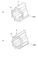
- 4 (a) to 4 (d) are perspective views of other examples of the rigidity adding portion.
- 5 (a) to 5 (c) are perspective views of still another example of the rigidity adding portion.
- 6A and 6B are perspective views of still another example of the rigidity adding portion.
- FIG. 7A to FIG. 7C are perspective views of still another example of the rigidity adding portion.
- FIG. 8A and FIG. 8B are perspective views of still another example of the rigidity adding portion.
- the wire harness according to the present embodiment includes a conductive path and a wire harness exterior member that accommodates and protects the conductive path.
- the exterior member for a wire harness is a resin or metal tube, and has a rigidity adding portion for adding rigidity.
- FIG. 1 is a schematic view showing a wiring state of a wire harness according to the present invention.
- 2 is a configuration diagram of a wire harness
- FIG. 3 is a perspective view of an exterior member
- FIGS. 4A to 8B are perspective views of another example of a rigidity adding portion.
- a wire harness including the wire harness exterior member of the embodiment is routed to a hybrid vehicle (which may be an electric vehicle or a general vehicle) will be described.
- reference numeral 1 indicates a hybrid vehicle.
- the hybrid vehicle 1 is a vehicle that mixes and drives the two powers of the engine 2 and the motor unit 3. Electric power from a battery 5 (in other words, a battery pack) is supplied to the motor unit 3 via the inverter unit 4.
- a battery 5 in other words, a battery pack
- the engine 2, the motor unit 3, and the inverter unit 4 are mounted in an engine room 6 at a position close to the front wheels and the like.
- the battery 5 is mounted on the rear part 7 of the automobile close to the rear wheels.
- the battery 5 may be mounted in an automobile room that exists behind the engine room 6.
- the motor unit 3 and the inverter unit 4 are electrically connected by a high-voltage wire harness 8.
- the battery 5 and the inverter unit 4 are also electrically connected by a high-voltage wire harness 9.
- the intermediate part 10 of the wire harness 9 is routed on the ground side of the vehicle body underfloor 11. Further, the wire harness 9 is routed substantially parallel along the vehicle body underfloor 11.
- the vehicle body underfloor 11 is a known body and a so-called panel member, and a through hole (not shown) is formed at a predetermined position. The wire harness 9 is inserted through the through hole.
- the wire harness 9 and the battery 5 are electrically connected via a junction block 12 provided in the battery 5.
- the rear end 13 of the wire harness 9 is electrically connected to the junction block 12 by a known method.
- the front end 14 side of the wire harness 9 is electrically connected to the inverter unit 4 by a known method.
- the motor unit 3 has a motor (not shown) and a generator (not shown).
- the inverter unit 4 includes an inverter (not shown) and a converter (not shown).
- the motor unit 3 is formed as a motor assembly including a shield case (not shown).
- the inverter unit 4 is also formed as an inverter assembly including a shield case (not shown).
- the battery 5 is of Ni-MH type or Li-ion type and is modularized. It is also possible to use a power storage device such as a capacitor.
- the battery 5 is not particularly limited as long as it can be used for the hybrid vehicle 1 and the electric vehicle.
- the wire harness 9 is a high-voltage member for electrically connecting the inverter unit 4 and the battery 5 as described above, and includes a high-voltage coaxial composite conductive path 15 (that is, a conductive path) and an exterior member 16 ( That is, it is comprised including the exterior member for wire harnesses.
- the wire harness 9 having such a configuration is routed so as to be hidden beside a lean hose (not shown), for example, under the vehicle body floor 11.
- the single high-voltage coaxial composite conductive path 15 has a plus circuit and a minus circuit. That is, the high-voltage coaxial composite conductive path 15 has two systems. Specifically, the high-voltage coaxial composite conductive path 15 covers the first conductive path 17 having a circular cross section located at the center of the high-voltage coaxial composite conductive path 15 and the outer periphery of the first conductive path 17 with a predetermined thickness. A first insulator 18.
- the high-voltage coaxial composite conductive path 15 includes a second conductive path 19 provided outside the first insulator 18 and a second insulator 20 that covers the outer periphery of the second conductive path 19 with a predetermined thickness.
- the high-voltage coaxial composite conductive path 15 includes an electromagnetic shield member 21 provided outside the second insulator 20 and a sheath 22 that covers the outer periphery of the electromagnetic shield member 21 with a predetermined thickness.
- a known high-voltage electric wire including a conductor and an insulator, a conductive wire such as a shielded electric wire, a cabtire cable, and the like can be given.
- the number of conductive paths may be at least one.
- the high-voltage coaxial composite conductive path 15 has two systems in the present embodiment, but is not limited to this, and may be three systems, n systems. Further, the high-voltage coaxial composite conductive path 15 may be configured without the sheath 22.
- the exterior member 16 is a resin tube for accommodating and protecting the high-voltage coaxial composite conductive path 15, and includes a bent tube portion 23 and a non-bent tube portion 24 (that is, a straight tube portion). .)
- the bent pipe portion 23 becomes a bent portion when the wire harness 9 is transported or routed, and the non-bent pipe portion 24 continues to the bent pipe portion 23.
- the non-bending tube portion 24 is provided as a portion that is difficult to bend.
- the exterior member 16 is a resin molded product obtained by extruding a desired resin material in the present embodiment.
- the exterior member 16 is not limited to resin, and may be made of metal as long as it has a rigidity adding portion 28 described later.
- the bending pipe part 23 and the non-bending pipe part 24 are each formed in multiple numbers in this embodiment, at least one should just be formed and the number is not specifically limited. That is, the configuration may be such that one bending tube portion 23 is provided and one non-bending tube portion 24 is continuously formed on both sides. Alternatively, the configuration may be such that one non-bending tube portion 24 is formed and one bending tube portion 23 is continuously formed on both sides thereof.
- the bending tube portion 23 is formed in a bellows tube shape having a plurality of concave portions 25 and convex portions 26 continuously formed in the circumferential direction of the outer surface in the longitudinal direction.
- the length of the bending pipe portion 23 is set according to the bending range.
- the bending pipe part 23 is formed in a bendable part having flexibility (in other words, flexibility).
- the bending pipe part 23 is formed in the same part as a well-known corrugated tube in this embodiment.
- the bending tube portion 23 is not limited to the bellows tube shape as long as it is a bendable shape.
- the bent tube portion 23 is formed so that its cross-sectional shape matches the cross-sectional shape of the non-bent tube portion main body 27 described later (this is an example and may have a different cross-sectional shape).
- the exterior member 16 has the same shape as the corrugated tube as described above, it can be regarded as a “cortube” or a “partially formed corrugated tube”.
- the exterior member 16 is formed in a shape in which no slit is provided (that is, there is no stomach split) along the tube axis direction (that is, the longitudinal direction).
- the reason for not providing the slit is to increase the rigidity and strength.
- moisture content in the exterior member 16 is also mentioned.
- the high-voltage coaxial composite conductive path 15 is difficult to protrude from the bent portion of the exterior member 16.
- the non-bending tube portion 24 has a non-bending tube portion main body 27 (that is, a straight tube portion main body) and a pair of rigidity adding portions 28.
- the non-bending tube portion main body 27 is formed to be thin as will be described later. Further, the non-bending tube portion main body 27 is formed in a straight tube shape having a circular cross section.
- the cross section of the non-bending tube portion main body 27 is not limited to a circle, and may be an ellipse, an oval, a substantially rectangle, or the like. For example, see FIGS. 4A to 8B for the cross-sectional shape. ).
- the pair of rigidity adding portions 28 are provided in the non-bending tube portion main body 27 in order to add rigidity.
- a pair of rigidity addition part 28 is formed so that the non-bending pipe part main body 27 may become a part which does not bend at the time of manufacture of a wire harness 9, transportation, and also at the time of route routing.
- the part which does not bend means the part which does not give flexibility positively. That is, it can also be said that it does not bend.
- the non-bending pipe part 24 can be regarded as a “straight pipe part” or a “straight pipe part” because the non-bending pipe part body 27 has a straight tube shape.
- the thickness of the non-bending tube main body 27 is set to a thickness having a necessary minimum strength. That is, the non-bending tube portion main body 27 is formed thin.
- the rigidity adding portion 28 is provided so as to supplement the rigidity so as to be equal to or more than the lowered rigidity.
- the non-bending tube portion 24 is increased in the moment of section by providing the rigidity adding portion 28.
- the rigidity adding portion 28 is formed as a rigidity adding portion for preventing the non-bending tube portion main body 27 from being bent even when the non-bending tube portion main body 27 is formed thin. As for the bending, for example, when being assembled and fixed to the vehicle body underfloor 11, a slight bending that does not hinder the workability is allowed.
- the rigidity adding portion 28 is formed in a shape that can resist the force in the direction indicated by the arrow P in FIG. 3 (that is, its own weight, the weight of the high-voltage coaxial composite conductive path 15 accommodated, etc.).
- the rigidity adding portion 28 is formed so as to protrude from the lower portion and the upper portion of the outer surface of the non-bent tube portion main body 27. That is, the rigidity adding portion 28 protrudes from the outer surface of the non-bending tube portion main body 27.
- the lower part and the upper part coincide with the vertically lower part and the vertically upper part of the non-bending pipe part main body 27 when the wire harness 9 is fixed to the vehicle body underfloor 11.
- the rigidity adding portion 28 is disposed at the lower portion and the upper portion and is formed to be a pair.
- the rigidity addition part 28 is not limited to a pair, What is necessary is just to be formed in the lower part of the non-bending pipe part main body 27 at least.
- the pair of rigidity adding portions 28 are formed so as to extend straight along the axial direction of the non-bending tube portion main body 27.
- the pair of rigidity adding portions 28 are formed in a ridge shape having a rectangular cross section (in other words, a rib shape) (other shapes will be described later).
- the exterior member 16 can be extruded because the rigidity added portion 28 is formed in the shape described above. If extrusion molding is possible, the long exterior member 16 can be molded.
- the lower rigidity addition part 28 of the pair of rigidity addition parts 28 is used as a chipping-resistant part 29 for withstanding chipping.
- the lower rigidity adding portion 28 which is the chipping-resistant portion 29 can withstand a stepping stone or the like when the vehicle travels, and can prevent the non-bending tube portion main body 27 and the internal conductive path from being affected.
- the lower rigidity addition part 28 which is the chipping-resistant part 29 is effective also when it rides on a curbstone etc. from the shape and arrangement
- the lower rigidity addition portion 28 is also used to improve durability against external factors such as curbs.
- the rigidity adding portion 28 is also formed as a portion for expanding the surface area of the outer surface of the non-bending tube portion main body 27. Since the radiation amount of heat increases by the surface integral of the rigidity adding portion 28, the non-bending tube portion 24 can enhance the heat radiation effect (that is, the cooling effect). Since the rigidity adding portion 28 is a portion that can improve heat dissipation as described above, it is also used as the heat radiating portion 30.
- FIG. 4A shows the rigidity adding portion 28 described above.
- the rigidity adding portion 128 is provided as a rigidity adding portion so as to protrude outward from the lower portion and the upper portion of the outer surface of the non-bending tube portion main body 27.
- Three rigidity adding portions 128 are arranged along the arrow P direction (the number is an example).
- the plurality of rigidity adding portions 128 are provided in upper and lower three pairs.
- the plurality of rigidity adding portions 128 are formed so as to extend straight along the axial direction of the non-bending tube portion main body 27.
- the plurality of rigidity adding portions 128 are formed in a ridge shape (in other words, a rib shape) having a rectangular cross section.
- Reference numeral 129 indicates a chipping resistant portion.
- the rigidity adding portion 128 is also used as a heat radiating portion (reference number omitted).
- the rigidity adding portion 228 is provided as a rigidity adding portion so as to protrude outward from the lower and upper portions of the outer surface of the non-bending tube portion main body 27.
- the rigidity adding portion 228 is provided in a total of six, ie, a pair of upper and lower ones arranged along the arrow P direction and two pairs of upper and lower ones arranged radially (the number is an example).
- the plurality of rigidity adding portions 228 are formed so as to extend straight along the axial direction of the non-bending tube portion main body 27.
- the plurality of rigidity adding portions 228 are formed in a ridge shape having a rectangular cross section (in other words, a rib shape).
- Reference numeral 229 indicates a chipping resistant portion.
- the rigidity adding portion 228 is also used as a heat radiating portion (reference numeral omitted).
- the rigidity adding portion 328 protrudes outward from the lower and upper portions of the outer surface of the non-bending tube body 27 as an additional portion of rigidity, and from the left and right portions of the outer surface. It is provided so as to protrude outward.
- the rigidity adding portion 328 is provided in a total of eight pairs of upper and lower ones arranged along the direction of arrow P, two upper and lower pairs arranged radially, and one pair of left and right (the number is an example).
- the plurality of rigidity adding portions 328 are formed so as to extend straight along the axial direction of the non-bending tube portion main body 27.
- the plurality of rigidity adding portions 328 are formed in a ridge shape (in other words, a rib shape) having a rectangular cross section. In this case, there is an advantage that assembly can be performed without worrying about the upper and lower sides, and an advantage that rigidity can be increased in all directions.
- Reference numeral 329 indicates a chipping resistant portion.
- the rigidity adding portion 328 is also used as a heat radiating portion (reference numeral omitted).
- the rigidity adding portion 428 is formed by deforming the lower and upper portions, the left portion and the right portion of the non-bending tube main body 27 inward as shown in FIG.
- the rigidity adding portion 428 is formed of a total of four, one pair of upper and lower ones arranged along the arrow P direction and one pair of left and right (the number is an example).
- the plurality of rigidity adding portions 428 are formed so as to extend straight along the axial direction of the non-bending tube portion main body 27.
- the plurality of rigidity adding portions 428 are formed in a ridge shape (in other words, a rib shape) having a substantially U-shaped cross section.
- the rigidity adding portion 528 is provided as a rigidity adding portion so as to protrude inward from the lower and upper portions of the inner surface of the non-bending tube portion main body 27. That is, the rigidity adding portion 28 protrudes from the inner surface of the non-bending tube portion main body 27.
- the rigidity adding portion 528 is provided in a total of four, ie, a pair of upper and lower ones arranged along the arrow P direction and a pair of left and right ones (the number is an example).
- the plurality of rigidity adding portions 528 are formed so as to extend straight along the axial direction of the non-bending tube portion main body 27.
- the plurality of rigidity adding portions 528 are formed in a ridge shape (in other words, a rib shape) having a rectangular cross section.
- the rigidity adding portion 628 is formed by deforming the lower and upper portions, the left portion and the right portion of the non-bending tube portion main body 27 as the rigidity adding portions outward as shown in the drawing.
- the rigidity adding portion 628 is formed by a total of four of a pair of upper and lower ones arranged along the arrow P direction and a pair of left and right (the number is an example).
- the plurality of rigidity adding portions 628 are formed so as to extend straight along the axial direction of the non-bending tube portion main body 27.
- the plurality of rigidity adding portions 628 are formed in a ridge shape (in other words, a rib shape) having a semicircular cross section.
- Reference numeral 629 indicates an anti-chipping portion.
- the rigidity adding portion 728 is formed by deforming the left and right portions of the non-bending tube portion main body 27 inward as shown in the drawing as a rigidity adding portion.
- the pair of rigidity adding portions 728 are formed so as to extend straight along the axial direction of the non-bending tube portion main body 27.
- the pair of rigidity adding portions 728 are formed in a shape that includes a press line when the non-bending tube portion main body 27 is made of metal, for example.
- the non-bending tube portion main body 27 is not limited to metal, and may be made of resin and extruded into the shape shown in FIG.
- the rigidity adding portion 828a is formed by deforming the non-bending tube portion main body 27 into, for example, a substantially regular hexagonal shape as a rigidity adding portion.
- the rigidity adding portion 828a corresponds to all of the deformation of the non-bending tube portion main body 27 from a circular shape to a polygonal shape.
- the rigidity adding portion 828a is also formed so that the surface area of the non-bending tube portion main body 27 is larger than that of a circular cross section.
- the rigidity adding portion 828a has a portion extending along the arrow P direction, this portion acts so as to resist bending. Since the rigidity adding portion 828a increases the surface area as described above, the heat dissipation performance of the non-bending tube portion main body 27 can be increased by the increase.
- the non-bending pipe part main body 27 may be deform
- the non-bending tube portion main body 27 may be deformed into, for example, a substantially regular decagonal shape to form the rigidity adding portion 828c (the number of corners is an example).
- the non-bending tube portion main body 27 may be deformed into, for example, a substantially cross shape to form the rigidity adding portion 928a. Further, as shown in FIG. 8B, the non-bending tube portion main body 27 may be deformed into, for example, a star shape to form the rigidity adding portion 928b.
- At least one rigid addition portion 28 as a rigid addition portion is a non-bending tube portion main body of the exterior member 16. 27, the second moment of section of the non-bending tube body 27 can be increased by the rigidity adding portion 28. As a result, it is easy to ensure the necessary and sufficient rigidity. Therefore, it is possible to reduce the thickness of the non-bending tube portion main body 27, thereby reducing the weight and cost of the wire harness 9.
- the rigidity of the non-bending tube portion main body 27 can be ensured by the rigidity adding portion 28. Therefore, even if the non-bending tube portion main body 27 is thinned, the non-bending tube portion main body 27. Can be prevented. Therefore, workability at the time of manufacturing the wire harness 9 and workability at the time of fixing the wire harness 9 to the vehicle body underfloor 11 can be improved.
- the exterior member 16 (wire harness exterior member) is a tubular body harness exterior member that covers the high-voltage coaxial composite conductive path 15 (conductive path).
- the exterior member 16 has a non-bending pipe part main body 27 (straight pipe part main body) for routing under the vehicle body floor 11 of the automobile, and a rigidity adding part (28 for adding rigidity to the non-bending pipe part main body 27. , 128, 228, 328, 428, 528, 628, 728, 828a-c, 928a-b).
- the rigidity adding portion is formed by protruding from the outer surface of the non-bending tube portion main body 27 or by deforming the non-bending tube portion main body 27 outward.
- the rigidity adding portion is formed by protruding on the inner surface of the non-bending tube portion main body 27, or the non-bending tube portion main body 27 is deformed inward.
- the rigidity adding portion is formed so that the surface area of the outer surface of the non-bending tube portion main body 27 is larger than that in the case where the cross section of the non-bending tube portion main body 27 is circular.
- the rigidity adding portion is formed in a shape extending along the axial direction of the non-bending tube portion main body 27.
- the exterior member 16 is continuous to the non-bending pipe part 24 (straight pipe part) formed as a non-bending part including the non-bending pipe part main body 27 and the rigidity addition part, and the non-bending pipe part 24, And a bent pipe portion 23 formed as a bent portion.
- the rigidity adding portion is disposed on the vertical lower side of the outer surface of the non-bending tube portion main body 27 when being fixed to the vehicle body floor bottom 11.
- the rigidity adding portion is also disposed on the vertical upper side of the outer surface of the non-bending tube portion main body 27 when being fixed to the vehicle body floor bottom 11.
- the wire harness 9 includes the exterior member 16 of any one of the above (1) to (8) and the high-voltage coaxial composite conductive path 15 (conductive path) covered with the exterior member 16.
- the wire harness exterior member and wire harness according to the present invention are useful in that a wire harness exterior member and wire harness capable of being thinned can be provided.
- SYMBOLS 1 Hybrid vehicle (automobile), 2 ... Engine, 3 ... Motor unit, 4 ... Inverter unit, 5 ... Battery, 6 ... Engine room, 7 ... Car rear part, 8, 9 ... Wire harness, 10 ... Middle part, 11 ... Under the car body floor, 12 ... junction block, 13 ... rear end, 14 ... front end, 15 ... high-voltage coaxial composite conductive path (conductive path), 16 ... exterior member (exterior member for wire harness), 17 ... first conductive path, 18 ... 1st insulator, 19 ... second conductive path, 20 ... second insulator, 21 ... electromagnetic shield member, 22 ... sheath, 23 ... bend tube portion, 24 ...
- non-bend tube portion (straight tube portion), 25 ... concave , 26 ... convex part, 27 ... non-bent pipe part main body (straight pipe part main body), 28 ... rigidity added part, 29 ... chipping resistant part, 30 ... Thermal unit, 128,228,328,428,528,628,728,828a ⁇ c, 928a ⁇ b ... rigid additional section
Landscapes
- Engineering & Computer Science (AREA)
- Architecture (AREA)
- Civil Engineering (AREA)
- Structural Engineering (AREA)
- Mechanical Engineering (AREA)
- General Engineering & Computer Science (AREA)
- Details Of Indoor Wiring (AREA)
- Protection Of Pipes Against Damage, Friction, And Corrosion (AREA)
Description
本発明は、ワイヤハーネス用の外装部材、及びこの外装部材を含むワイヤハーネスに関する。
ハイブリッド自動車や電気自動車のバッテリーとインバータユニットとの間を電気的に接続する部材として、高圧用(すなわち、高電圧用。)のワイヤハーネスが用いられる。上記バッテリーとインバータユニットとの間を電気的に接続するワイヤハーネスの中には、複数本の高圧導電路と、これらを保護するための外装部材とを含むものがある(下記特許文献1参照。)。
ハイブリッド自動車や電気自動車などの自動車の分野においては、搭載される部品等の軽量化やコスト低減の実現に向けた努力及び検討が続けられている。このような中、本願発明者らは、ワイヤハーネスの軽量化やコスト低減にあたり外装部材の肉厚を薄くすることを考えている。しかしながら、単に外装部材の肉厚を薄くするだけでは実現が困難である。何故ならば、薄肉化された外装部材が長尺であればあるほど、自重などの影響によって撓みが生じ易い。このために、例えばワイヤハーネスの製造時における作業性や、ワイヤハーネスの車体への固定時等における作業性に支障を来してしまう可能性があるからである。
本発明は、上記した事情に鑑みてなされたもので、薄肉化を図ることが可能なワイヤハーネス用外装部材及びワイヤハーネスを提供することを課題とする。
前述した課題を解決するために、本発明に係るワイヤハーネス用外装部材及びワイヤハーネスは、下記(1)~(9)を特徴としている。
(1) 導電路を覆う管体形状のワイヤハーネス用外装部材であって、
自動車の車体床下に配索するためのストレート管部本体を有するとともに、該ストレート管部本体に剛性を付加するための剛性付加部を少なくとも一つ有するワイヤハーネス用外装部材。
(1) 導電路を覆う管体形状のワイヤハーネス用外装部材であって、
自動車の車体床下に配索するためのストレート管部本体を有するとともに、該ストレート管部本体に剛性を付加するための剛性付加部を少なくとも一つ有するワイヤハーネス用外装部材。
(2) (1)のワイヤハーネス用外装部材であって、
前記剛性付加部は、前記ストレート管部本体の外面に突設される、若しくは前記ストレート管部本体が外側へ変形することにより形成される。
前記剛性付加部は、前記ストレート管部本体の外面に突設される、若しくは前記ストレート管部本体が外側へ変形することにより形成される。
(3) (1)のワイヤハーネス用外装部材であって、
前記剛性付加部は、前記ストレート管部本体の内面に突設される、若しくは前記ストレート管部本体が内側へ変形することにより形成される。
前記剛性付加部は、前記ストレート管部本体の内面に突設される、若しくは前記ストレート管部本体が内側へ変形することにより形成される。
(4) (2)又は(3)のワイヤハーネス用外装部材であって、
前記剛性付加部は、前記ストレート管部本体の断面が円形の場合と比べて該ストレート管部本体の表面積が大きくなるように、形成される。
前記剛性付加部は、前記ストレート管部本体の断面が円形の場合と比べて該ストレート管部本体の表面積が大きくなるように、形成される。
(5) (1)~(4)のいずれか1つのワイヤハーネス用外装部材であって、
前記剛性付加部は、前記ストレート管部本体の軸方向に沿ってのびる形状に形成される。
前記剛性付加部は、前記ストレート管部本体の軸方向に沿ってのびる形状に形成される。
(6) (1)~(5)のいずれか1つのワイヤハーネス用外装部材であって、
前記ストレート管部本体及び前記剛性付加部を含み曲がりにくい部分として形成されるストレート管部と、該ストレート管部に連続し、曲げ部分として形成される曲げ管部とを有する。
前記ストレート管部本体及び前記剛性付加部を含み曲がりにくい部分として形成されるストレート管部と、該ストレート管部に連続し、曲げ部分として形成される曲げ管部とを有する。
(7) (1)~(6)のいずれか1つのワイヤハーネス用外装部材であって、
前記剛性付加部は、前記ストレート管部本体の外面のうち、前記車体床下への固定時における鉛直下方側に配置される。
前記剛性付加部は、前記ストレート管部本体の外面のうち、前記車体床下への固定時における鉛直下方側に配置される。
(8) (1)~(7)のいずれか1つのワイヤハーネス用外装部材であって、
前記剛性付加部は、前記ストレート管部本体の外面のうち、前記車体床下への固定時における鉛直上方側にも配置される。
前記剛性付加部は、前記ストレート管部本体の外面のうち、前記車体床下への固定時における鉛直上方側にも配置される。
(9) (1)~(8)のいずれか1つのワイヤハーネス用外装部材と、該ワイヤハーネス用外装部材に覆われる導電路とを含むワイヤハーネス。
上記(1)のワイヤハーネス用外装部材によれば、剛性を付加するための剛性付加部を少なくとも一つ有することから、この剛性付加部によりストレート管部本体の断面二次モーメントを大きくすることができる。この結果、必要十分な剛性を確保し易い。従って、上記(1)のワイヤハーネス用外装部材によれば、ストレート管部本体の薄肉化を図ることができ、以て軽量化やコスト低減を図ることができる。また、上記(1)のワイヤハーネス用外装部材によれば、剛性付加部にて剛性を確保することができることから、ストレート管部本体の薄肉化を図ってもストレート管部本体の撓みを防止できる。従って、上記(1)のワイヤハーネス用外装部材によれば、例えばワイヤハーネス製造時における作業性や、ワイヤハーネスの車体への固定時等における作業性を向上できる。さらに、上記(1)のワイヤハーネス用外装部材によれば、剛性付加部を有することから、この剛性付加部を例えば縁石等の外因に対する耐久性向上を図るために用いることができる。
上記(2)のワイヤハーネス用外装部材では、剛性付加部が、ストレート管部本体の外面に突設される、若しくはストレート管部が内側へ変形することにより形成される。このため、上記(2)のワイヤハーネス用外装部材によれば、剛性付加部を剛性の付加部分以外に、耐チッピング性能を確保するために、また、放熱性の向上を図るために用いることができる。
上記(3)のワイヤハーネス用外装部材では、剛性付加部が、ストレート管部本体の内面に突設される、若しくはストレート管部が内側へ変形することにより形成される。このため、上記(3)のワイヤハーネス用外装部材によれば、剛性付加部を、剛性を付加するため以外に、放熱性の向上を図るために用いることができる。また、上記(3)のワイヤハーネス用外装部材によれば、剛性付加部が外側に突出しないことから、後付け部品を装着し易く、また、ワイヤハーネスの車体への固定時において、作業の邪魔になりにくい。
上記(4)のワイヤハーネス用外装部材によれば、ストレート管部本体の断面が円形である場合と比べて、ストレート管部本体の表面積が大きいことから、表面積を増大させた分だけ放熱性が高い。
上記(5)のワイヤハーネス用外装部材によれば、剛性付加部がストレート管部本体の軸方向に沿ってのびる形状に形成されることから、押出成型可能なワイヤハーネス用外装部材を提供できる。
上記(6)のワイヤハーネス用外装部材によれば、ストレート管部と曲げ管部とを有するワイヤハーネス用外装部材を提供できる。
上記(7)のワイヤハーネス用外装部材では、ストレート管部本体の外面のうち、車体床下への固定時における少なくとも鉛直下方側に剛性付加部が配置される。このため、剛性付加部を、剛性を付加するため以外に、耐チッピング性能を確保するために、また、例えば縁石等の外因に対する耐久性向上を図るために用いることができる。
上記(8)のワイヤハーネス用外装部材によれば、ストレート管部本体の外面のうち、車体床下への固定時における鉛直下方側と、その反対側に位置する鉛直上方側に剛性付加部が配置されることから、ストレート管部本体の剛性を高めることができる。これにより、上記(8)のワイヤハーネス用外装部材によれば、ストレート管部本体の更なる薄肉化を図ることができる。
上記(9)のワイヤハーネスによれば、上記(1)~(8)のいずれか1つのワイヤハーネス用外装部材を含むことから、軽量化やコスト低減を図ることができ、さらには、耐チッピング性能や作業性等も良好なワイヤハーネスを提供できる。
本実施形態に係るワイヤハーネスは、導電路と、この導電路を収容保護するワイヤハーネス用外装部材とを含む。ワイヤハーネス用外装部材は、樹脂製又は金属製の管体であり、剛性を付加するための剛性付加部を有する。
以下、図1~図8を参照しながら本発明に係るワイヤハーネス用外装部材の実施形態を説明する。図1は本発明に係るワイヤハーネスの配索状態を示す概略図である。また、図2はワイヤハーネスの構成図、図3は外装部材の斜視図、図4(a)~図8(b)は他の例となる剛性付加部の斜視図である。
本実施形態においては、ハイブリッド自動車(電気自動車や一般的な自動車であってもよいものとする)に実施形態のワイヤハーネス用外装部材を含むワイヤハーネスを配索する例を挙げて説明する。
図1において、引用符号1はハイブリッド自動車を示す。ハイブリッド自動車1は、エンジン2及びモータユニット3の二つの動力をミックスして駆動する車両である。モータユニット3にはインバータユニット4を介してバッテリー5(換言すれば、電池パック。)からの電力が供給される。エンジン2、モータユニット3、及びインバータユニット4は、この例においては前輪等に近い位置のエンジンルーム6に搭載される。また、バッテリー5は、後輪等に近い自動車後部7に搭載される。尚、バッテリー5は、エンジンルーム6の後方に存在する自動車室内に搭載してもよい。
モータユニット3とインバータユニット4は、高圧用のワイヤハーネス8により電気的に接続される。また、バッテリー5とインバータユニット4も高圧用のワイヤハーネス9により電気的に接続される。ワイヤハーネス9は、その中間部10が車体床下11の地面側に配索される。また、ワイヤハーネス9は、車体床下11に沿って略平行に配索される。車体床下11は、公知のボディであるとともに所謂パネル部材であって、所定位置には貫通孔(図示せず。)が形成される。この貫通孔には、ワイヤハーネス9が挿通される。
ワイヤハーネス9とバッテリー5は、このバッテリー5に設けられるジャンクションブロック12を介して電気的に接続される。ジャンクションブロック12には、ワイヤハーネス9の後端13が公知の方法で電気的に接続される。ワイヤハーネス9の前端14側は、インバータユニット4に対し公知の方法で電気的に接続される。
モータユニット3は、モータ(図示せず。)及びジェネレータ(図示せず。)を有する。また、インバータユニット4は、インバータ(図示せず。)及びコンバータ(図示せず。)を有する。モータユニット3は、シールドケース(図示せず。)を含むモータアッセンブリとして形成される。また、インバータユニット4もシールドケース(図示せず。)を含むインバータアッセンブリとして形成される。バッテリー5は、Ni-MH系やLi-ion系のものであって、モジュール化されている。尚、例えばキャパシタのような蓄電装置を使用することも可能である。バッテリー5は、ハイブリッド自動車1や電気自動車に使用可能であれば特に限定されない。
先ず、ワイヤハーネス9の構成及び構造について説明をする。ワイヤハーネス9は、上記の如くインバータユニット4とバッテリー5とを電気的に接続するための高圧用の部材であって、高圧同軸複合導電路15(すなわち、導電路。)と、外装部材16(すなわち、ワイヤハーネス用外装部材。)とを含んで構成される。このような構成のワイヤハーネス9は、車体床下11において例えば図示しないリーンホースの横で隠れるように経路配索される。
図2において、高圧同軸複合導電路15は、この一本でプラス回路及びマイナス回路を有する。すなわち、高圧同軸複合導電路15は、二系統の回路を有する。具体的には、高圧同軸複合導電路15は、高圧同軸複合導電路15の中心に位置する断面円形状の第一導電路17と、この第一導電路17の外周を所定厚さで被覆する第一絶縁体18と、を有する。また、高圧同軸複合導電路15は、第一絶縁体18の外側に設けられる第二導電路19と、この第二導電路19の外周を所定厚さで被覆する第二絶縁体20と、を有する。さらに、高圧同軸複合導電路15は、第二絶縁体20の外側に設けられる電磁シールド部材21と、この電磁シールド部材21の外周を所定厚さで被覆するシース22とを含む。
導電路に関し、高圧同軸複合導電路15以外としては、導体と絶縁体とを含む公知の高圧用の電線や、シールド電線、キャブタイヤケーブル等の導電路が挙げられる。尚、導電路の本数は少なくとも一本であればよい。
高圧同軸複合導電路15は、本実施形態においては二系統であるが、これに限らず三系統…、n系統であってもよい。また、高圧同軸複合導電路15は、シース22を有しない構成であってもよい。
図2及び図3において、外装部材16は、高圧同軸複合導電路15を収容保護するための樹脂製の管体であって、曲げ管部23と、非曲げ管部24(すなわち、ストレート管部。)とを有する。曲げ管部23は、ワイヤハーネス9の輸送時や経路配索時に曲げ部分となり、この曲げ管部23に非曲げ管部24が連続する。非曲げ管部24は、曲がりにくい部分として設けられる。外装部材16は、本実施形態においては所望の樹脂材料を押し出し成形することにより得られる樹脂成型品である。尚、外装部材16は、樹脂製に限定されず、後述する剛性付加部28を有するのであれば金属製のものであってもよい。
尚、曲げ管部23及び非曲げ管部24は、本実施形態においてはそれぞれ複数形成されているが、少なくとも一つ形成されていればよく、その数は特に限定されない。すなわち、曲げ管部23を一つにするとともに、この両側に非曲げ管部24を一つずつ連続して形成する構成であってもよい。或いは、非曲げ管部24を一つにするとともに、この両側に曲げ管部23を一つずつ連続して形成するような構成であってもよい。
曲げ管部23は、その外面の周方向に一周に亘って形成された凹部25及び凸部26を、その長手方向に複数連続して有する蛇腹管形状に形成される。曲げ管部23は、曲げ範囲に応じてその長さが設定される。曲げ管部23は、柔軟性(換言すれば、可撓性。)を有して曲げ可能な部分に形成される。曲げ管部23は、本実施形態において公知のコルゲートチューブと同様の部分に形成される。尚、曲げ管部23は、曲げ可能な形状であれば、上記蛇腹管形状に限定されない。
曲げ管部23は、本実施形態においては、その断面形状が後述する非曲げ管部本体27の断面形状に合うように形成される(一例であり、異なる断面形状であってもよい。)。
外装部材16は、上記の如くコルゲートチューブと同様の形状部分を有することから、「コルチューブ」や「部分形成コルゲートチューブ」などとみなすことができる。
外装部材16は、その管軸方向(すなわち、長手方向。)に沿ってスリットを設けない(すなわち、腹割きのない。)形状に形成される。スリットを設けない理由としては、剛性や強度を高める点が挙げられる。また、外装部材16内への水分の浸入を防止して防水性の向上を図る点も挙げられる。さらには、例えば外装部材16の曲げた部分から高圧同軸複合導電路15がはみ出しにくくする点も挙げられる。
非曲げ管部24は、非曲げ管部本体27(すなわち、ストレート管部本体。)と、一対の剛性付加部28とを有する。非曲げ管部本体27は、後述するように薄肉に形成される。また、非曲げ管部本体27は、断面円形のストレートチューブ形状に形成される。尚、非曲げ管部本体27の断面は、円形に限らず、楕円形や長円形、略矩形等であってもよい。断面形状は例えば図4(a)~図8(b)参照。)。一対の剛性付加部28は、剛性を付加するために非曲げ管部本体27に設けられる。一対の剛性付加部28は、ワイヤハーネス9の製造時や輸送時、さらには経路配索時に非曲げ管部本体27が曲がらない部分となるように形成される。尚、上記曲がらない部分とは、可撓性を積極的に持たせない部分という意味である。すなわち、撓まない部分とも言える。非曲げ管部24は、非曲げ管部本体27がストレートチューブ形状であることから、「直管部」や「ストレート管部」ともみなすことができる。
非曲げ管部本体27は、その肉厚が必要最低限の強度を有する厚みに設定される。すなわち、非曲げ管部本体27は、薄肉に形成される。尚、薄肉となる厚みの設定に伴い剛性の低下が懸念されるが、この剛性の低下分以上となるように剛性付加部28を設けて剛性を補う。非曲げ管部24は、剛性付加部28を設けることにより断面二次モーメントが増加する。
剛性付加部28は、非曲げ管部本体27を薄肉に形成した場合であっても、この非曲げ管部本体27に撓みを生じさせないようにするための剛性の付加部分として形成される。尚、撓みに関しては、例えば車体床下11に組み付け固定する際に、作業性に支障を来さない程度の僅かな撓みは許容される。剛性付加部28は、図3中に矢印Pで示す方向の力(すなわち、自重や、収容される高圧同軸複合導電路15の重み等。)に抗することができる形状に形成される。
剛性付加部28は、本実施形態においては、非曲げ管部本体27の外面のうちの下部及び上部から突出するように形成される。すなわち、剛性付加部28は、非曲げ管部本体27の外面に突設される。この下部及び上部は、車体床下11へのワイヤハーネス9の固定時における非曲げ管部本体27の鉛直下方及び鉛直上方に一致する。剛性付加部28は、下部及び上部に配置され、一対となるように形成される。尚、剛性付加部28は、一対に限定されるものでなく、少なくとも非曲げ管部本体27の下部に形成されていればよい。
一対の剛性付加部28は、非曲げ管部本体27の軸方向に沿って真っ直ぐのびるように形成される。一対の剛性付加部28は、断面矩形の突条形状(換言すれば、リブ形状。)に形成される(他の形状については後述する。)。外装部材16は、剛性付加部28が上記形状に形成されることから、押出成型可能である。尚、押出成型が可能であれば、長尺な外装部材16の成型が可能になる。
一対の剛性付加部28のうちの下側の剛性付加部28は、チッピングに耐えるための耐チッピング部29として用いられる。耐チッピング部29である下側の剛性付加部28は、車両走行時において飛び石等があってもこれに耐え、非曲げ管部本体27や内部の導電路にまで影響を及ぼさないようにできる。また、耐チッピング部29である下側の剛性付加部28は、その形状及び配置から、例えば縁石等に乗り上げた場合にも有効である。このように、下側の剛性付加部28は、縁石等の外因に対する耐久性向上を図るためにも用いられる。
剛性付加部28は、非曲げ管部本体27の外面の表面積を広げるための部分としても形成される。非曲げ管部24は、剛性付加部28の表面積分だけ熱の放射量が増加することから、放熱効果(すなわち、冷却効果。)を高めることができる。剛性付加部28は、上記の如く放熱性を向上させることができる部分であることから、放熱部30としても用いられる。
以上のような剛性付加部28は、図4(b)~図4(d)、図5(a)~図5(c)、図6(a)~図6(b)、図7(a)~図7(c)、又は図8(a)~図8(b)に示す形状に変更してもよい。尚、図4(a)には上記説明の剛性付加部28が示されている。
図4(b)において、剛性付加部128は、剛性の付加部分として非曲げ管部本体27の外面の下部及び上部から外方へ突出するように設けられる。剛性付加部128は、矢印P方向に沿って三つずつ配設される(数は一例である。)。複数の剛性付加部128は、上下三つの対で設けられる。複数の剛性付加部128は、非曲げ管部本体27の軸方向に沿って真っ直ぐのびるように形成される。複数の剛性付加部128は、断面矩形の突条形状(換言すれば、リブ形状。)に形成される。尚、引用符号129は耐チッピング部を示す。剛性付加部128は、放熱部(符号省略。)としても用いられる。
図4(c)において、剛性付加部228は、剛性の付加部分として非曲げ管部本体27の外面の下部及び上部から外方へ突出するように設けられる。剛性付加部228は、矢印P方向に沿って配置される上下一対のものと、放射状に配置される上下二対のものの合計六つで設けられる(数は一例である。)。複数の剛性付加部228は、非曲げ管部本体27の軸方向に沿って真っ直ぐのびるように形成される。複数の剛性付加部228は、断面矩形の突条形状(換言すれば、リブ形状。)に形成される。尚、引用符号229は耐チッピング部を示す。剛性付加部228は、放熱部(符号省略。)としても用いられる。
図4(d)において、剛性付加部328は、剛性の付加部分として非曲げ管部本体27の外面の下部及び上部から外方へ突出するように、また、当該外面の左部及び右部から外方へ突出するように設けられる。剛性付加部328は、矢印P方向に沿って配置される上下一対のものと、放射状に配置される上下二対及び左右一対のものの合計八つで設けられる(数は一例である。)。複数の剛性付加部328は、非曲げ管部本体27の軸方向に沿って真っ直ぐのびるように形成される。複数の剛性付加部328は、断面矩形の突条形状(換言すれば、リブ形状。)に形成される。尚、この場合、上下を気にせずに組み付けをすることができるという利点や、全方向に対し剛性を高めることができるという利点を有する。引用符号329は耐チッピング部を示す。剛性付加部328は、放熱部(符号省略。)としても用いられる。
図5(a)において、剛性付加部428は、剛性の付加部分として非曲げ管部本体27の下部及び上部と、左部及び右部とが図示の如く内側に変形することにより形成される。剛性付加部428は、矢印P方向に沿って配置される上下一対のものと、左右一対のものの合計四つで形成される(数は一例である。)。複数の剛性付加部428は、非曲げ管部本体27の軸方向に沿って真っ直ぐのびるように形成される。複数の剛性付加部428は、断面略U字状の突条形状(換言すれば、リブ形状。)に形成される。
図5(b)において、剛性付加部528は、剛性の付加部分として非曲げ管部本体27の内面の下部及び上部から内方へ突出するように設けられる。すなわち、剛性付加部28は、非曲げ管部本体27の内面に突設される。剛性付加部528は、矢印P方向に沿って配置される上下一対のものと、左右一対のものの合計四つで設けられる(数は一例である。)。複数の剛性付加部528は、非曲げ管部本体27の軸方向に沿って真っ直ぐにのびるように形成される。複数の剛性付加部528は、断面矩形の突条形状(換言すれば、リブ形状。)に形成される。
図5(c)において、剛性付加部628は、剛性の付加部分として非曲げ管部本体27の下部及び上部と、左部及び右部とが図示の如く外側に変形することにより形成される。剛性付加部628は、矢印P方向に沿って配置される上下一対のものと、左右一対のものの合計四つで形成される(数は一例である。)。複数の剛性付加部628は、非曲げ管部本体27の軸方向に沿って真っ直ぐのびるように形成される。複数の剛性付加部628は、断面半円形の突条形状(換言すれば、リブ形状。)に形成される。尚、引用符号629は耐チッピング部を示す。
図6(a)において、剛性付加部728は、剛性の付加部分として非曲げ管部本体27の左部及び右部が図示の如く内側に変形することにより形成される。一対の剛性付加部728は、非曲げ管部本体27の軸方向に沿って真っ直ぐのびるように形成される。一対の剛性付加部728は、非曲げ管部本体27を例えば金属製とした場合、プレスラインを入れたような形状に形成される。尚、非曲げ管部本体27は、金属製に限らず、樹脂製で図6(a)に示す形状に押出成型してもよい。
尚、図6(b)に示す如く一対の剛性付加部728を非曲げ管部本体27の下部及び上部に配置してもよい。
図7(a)において、剛性付加部828aは、剛性の付加部分として非曲げ管部本体27が例えば略正六角形状に変形することにより形成される。剛性付加部828aは、非曲げ管部本体27が断面円形の状態から多角形に変形した分の全てが該当する。この場合、剛性付加部828aは、断面円形の場合と比べて非曲げ管部本体27の表面積が大きくなるようにも形成される。また、剛性付加部828aは、矢印P方向に沿ってのびる部分を有することから、この部分が撓みに抗するように作用する。剛性付加部828aは、上記の如く表面積を増大させることから、増大分だけ非曲げ管部本体27の放熱性を高めることができる。
尚、図7(b)に示す如く非曲げ管部本体27を例えば略正八角形状に変形させて剛性付加部828bを形成してもよい。また、図7(c)に示す如く非曲げ管部本体27を例えば略正十角形状に変形させて剛性付加部828cを形成してもよい(角の数は一例である。)。
さらに、図8(a)に示す如く非曲げ管部本体27を例えば略十字形状に変形させて剛性付加部928aを形成してもよい。また、図8(b)に示す如く非曲げ管部本体27を例えば星形状に変形させて剛性付加部928bを形成してもよい。
以上、図1~図8(b)を参照しながら説明してきたように、ワイヤハーネス9によれば、剛性の付加部分としての剛性付加部28を少なくとも一つ外装部材16の非曲げ管部本体27に有することから、剛性付加部28により非曲げ管部本体27の断面二次モーメントを増加できる。この結果、必要十分な剛性を確保し易い。従って、非曲げ管部本体27の薄肉化を図ることができ、以てワイヤハーネス9の軽量化やコスト低減を図ることができる。
また、ワイヤハーネス9によれば、剛性付加部28にて非曲げ管部本体27の剛性を確保することができることから、非曲げ管部本体27の薄肉化を図っても非曲げ管部本体27の撓みを防止することができる。従って、ワイヤハーネス9の製造時における作業性や、ワイヤハーネス9の車体床下11への固定時等における作業性を向上できる。
以下では、実施形態に係るワイヤハーネス9及び外装部材16について纏める。
(1)外装部材16(ワイヤハーネス用外装部材)は、高圧同軸複合導電路15(導電路)を覆う管体形状のワイヤハーネス用外装部材である。外装部材16は、自動車の車体床下11に配索するための非曲げ管部本体27(ストレート管部本体)を有するとともに、該非曲げ管部本体27に剛性を付加するための剛性付加部(28、128、228、328、428、528、628、728、828a~c、928a~b)を少なくとも一つ有する。
(2)外装部材16では、前記剛性付加部は、前記非曲げ管部本体27の外面に突設される、若しくは前記非曲げ管部本体27が外側へ変形することにより形成される。
(3)外装部材16では、前記剛性付加部は、前記非曲げ管部本体27の内面に突設される、若しくは前記非曲げ管部本体27が内側へ変形することにより形成される。
(4)外装部材16では、前記剛性付加部は、前記非曲げ管部本体27の断面が円形の場合と比べて該非曲げ管部本体27の外面の表面積が大きくなるように、形成される。
(5)外装部材16では、前記剛性付加部は、前記非曲げ管部本体27の軸方向に沿ってのびる形状に形成される。
(6)外装部材16は、前記非曲げ管部本体27及び前記剛性付加部を含み曲がりにくい部分として形成される非曲げ管部24(ストレート管部)と、該非曲げ管部24に連続し、曲げ部分として形成される曲げ管部23とを有する。
(7)外装部材16では、前記剛性付加部は、前記非曲げ管部本体27の外面のうち、前記車体床下11への固定時における鉛直下方側に配置される。
(8)外装部材16では、前記剛性付加部は、前記非曲げ管部本体27の外面のうち、前記車体床下11への固定時における鉛直上方側にも配置される。
(9)ワイヤハーネス9は、上記(1)~(8)のいずれか1つの外装部材16と、該外装部材16に覆われる高圧同軸複合導電路15(導電路)を含む。
(1)外装部材16(ワイヤハーネス用外装部材)は、高圧同軸複合導電路15(導電路)を覆う管体形状のワイヤハーネス用外装部材である。外装部材16は、自動車の車体床下11に配索するための非曲げ管部本体27(ストレート管部本体)を有するとともに、該非曲げ管部本体27に剛性を付加するための剛性付加部(28、128、228、328、428、528、628、728、828a~c、928a~b)を少なくとも一つ有する。
(2)外装部材16では、前記剛性付加部は、前記非曲げ管部本体27の外面に突設される、若しくは前記非曲げ管部本体27が外側へ変形することにより形成される。
(3)外装部材16では、前記剛性付加部は、前記非曲げ管部本体27の内面に突設される、若しくは前記非曲げ管部本体27が内側へ変形することにより形成される。
(4)外装部材16では、前記剛性付加部は、前記非曲げ管部本体27の断面が円形の場合と比べて該非曲げ管部本体27の外面の表面積が大きくなるように、形成される。
(5)外装部材16では、前記剛性付加部は、前記非曲げ管部本体27の軸方向に沿ってのびる形状に形成される。
(6)外装部材16は、前記非曲げ管部本体27及び前記剛性付加部を含み曲がりにくい部分として形成される非曲げ管部24(ストレート管部)と、該非曲げ管部24に連続し、曲げ部分として形成される曲げ管部23とを有する。
(7)外装部材16では、前記剛性付加部は、前記非曲げ管部本体27の外面のうち、前記車体床下11への固定時における鉛直下方側に配置される。
(8)外装部材16では、前記剛性付加部は、前記非曲げ管部本体27の外面のうち、前記車体床下11への固定時における鉛直上方側にも配置される。
(9)ワイヤハーネス9は、上記(1)~(8)のいずれか1つの外装部材16と、該外装部材16に覆われる高圧同軸複合導電路15(導電路)を含む。
本発明は本発明の主旨を変えない範囲で種々変更実施可能なことは勿論である。
本出願は、2012年8月23日出願の日本特許出願(特願2012-183752)に基づくものであり、その内容はここに参照として取り込まれる。
本発明に係るワイヤハーネス用外装部材及びワイヤハーネスによれば、薄肉化を図ることが可能なワイヤハーネス用外装部材及びワイヤハーネスを提供できる点で有用である。
1…ハイブリッド自動車(自動車)、 2…エンジン、 3…モータユニット、 4…インバータユニット、 5…バッテリー、 6…エンジンルーム、 7…自動車後部、 8、9…ワイヤハーネス、 10…中間部、 11…車体床下、 12…ジャンクションブロック、 13…後端、 14…前端、 15…高圧同軸複合導電路(導電路)、 16…外装部材(ワイヤハーネス用外装部材)、 17…第一導電路、 18…第一絶縁体、 19…第二導電路、 20…第二絶縁体、 21…電磁シールド部材、 22…シース、 23…曲げ管部、 24…非曲げ管部(ストレート管部)、 25…凹部、 26…凸部、 27…非曲げ管部本体(ストレート管部本体)、 28…剛性付加部、 29…耐チッピング部、 30…放熱部、 128、228、328、428、528、628、728、828a~c、928a~b…剛性付加部
Claims (9)
- 導電路を覆う管体形状のワイヤハーネス用外装部材であって、
自動車の車体床下に配索するためのストレート管部本体を有するとともに、該ストレート管部本体に剛性を付加するための剛性付加部を少なくとも一つ有する
ワイヤハーネス用外装部材。 - 前記剛性付加部は、前記ストレート管部本体の外面に突設される、若しくは前記ストレート管部本体が外側へ変形することにより形成される
請求項1に記載のワイヤハーネス用外装部材。 - 前記剛性付加部は、前記ストレート管部本体の内面に突設される、若しくは前記ストレート管部本体が内側へ変形することにより形成される
請求項1に記載のワイヤハーネス用外装部材。 - 前記剛性付加部は、前記ストレート管部本体の断面が円形の場合と比べて該ストレート管部本体の表面積が大きくなるように、形成される
請求項2又は3に記載のワイヤハーネス用外装部材。 - 前記剛性付加部は、前記ストレート管部本体の軸方向に沿ってのびる形状に形成される
請求項1~4のいずれか1項に記載のワイヤハーネス用外装部材。 - 前記ストレート管部本体及び前記剛性付加部を含み曲がりにくい部分として形成されるストレート管部と、該ストレート管部に連続し、曲げ部分として形成される曲げ管部とを有する
請求項1~5のいずれか1項に記載のワイヤハーネス用外装部材。 - 前記剛性付加部は、前記ストレート管部本体の外面のうち、前記車体床下への固定時における鉛直下方側に配置される
請求項1~6のいずれか1項に記載のワイヤハーネス用外装部材。 - 前記剛性付加部は、前記ストレート管部本体の外面のうち、前記車体床下への固定時における鉛直上方側にも配置される
請求項7に記載のワイヤハーネス用外装部材。 - 請求項1~8のいずれか1つに記載のワイヤハーネス用外装部材と、該ワイヤハーネス用外装部材に覆われる導電路とを含む
ワイヤハーネス。
Priority Applications (3)
| Application Number | Priority Date | Filing Date | Title |
|---|---|---|---|
| CN201380044010.9A CN104604056B (zh) | 2012-08-23 | 2013-08-23 | 线束外部部件和线束 |
| EP13830678.2A EP2889973B1 (en) | 2012-08-23 | 2013-08-23 | Wire harness exterior member and wire harness |
| US14/602,398 US9735556B2 (en) | 2012-08-23 | 2015-01-22 | Wire harness exterior member and wire harness |
Applications Claiming Priority (2)
| Application Number | Priority Date | Filing Date | Title |
|---|---|---|---|
| JP2012-183752 | 2012-08-23 | ||
| JP2012183752A JP6089292B2 (ja) | 2012-08-23 | 2012-08-23 | ワイヤハーネス用外装部材及びワイヤハーネス |
Related Child Applications (1)
| Application Number | Title | Priority Date | Filing Date |
|---|---|---|---|
| US14/602,398 Continuation US9735556B2 (en) | 2012-08-23 | 2015-01-22 | Wire harness exterior member and wire harness |
Publications (1)
| Publication Number | Publication Date |
|---|---|
| WO2014030739A1 true WO2014030739A1 (ja) | 2014-02-27 |
Family
ID=50150042
Family Applications (1)
| Application Number | Title | Priority Date | Filing Date |
|---|---|---|---|
| PCT/JP2013/072550 Ceased WO2014030739A1 (ja) | 2012-08-23 | 2013-08-23 | ワイヤハーネス用外装部材及びワイヤハーネス |
Country Status (5)
| Country | Link |
|---|---|
| US (1) | US9735556B2 (ja) |
| EP (1) | EP2889973B1 (ja) |
| JP (1) | JP6089292B2 (ja) |
| CN (1) | CN104604056B (ja) |
| WO (1) | WO2014030739A1 (ja) |
Cited By (2)
| Publication number | Priority date | Publication date | Assignee | Title |
|---|---|---|---|---|
| CN107533886A (zh) * | 2015-05-08 | 2018-01-02 | 株式会社自动网络技术研究所 | 屏蔽导电路径 |
| DE112014007162B4 (de) * | 2014-11-12 | 2024-04-25 | Sumitomo Wiring Systems, Ltd. | Schutzrohr für elektrische Leitungen und Kabelbaum |
Families Citing this family (8)
| Publication number | Priority date | Publication date | Assignee | Title |
|---|---|---|---|---|
| JP5883486B2 (ja) * | 2014-07-01 | 2016-03-15 | 調和工業株式会社 | 油圧ホース用油漏れ防止材及び油漏れ防止方法並びに杭の施工方法 |
| EP2993749A1 (de) * | 2014-09-05 | 2016-03-09 | Nexans | Anordnung zur elektrischen verbindung von elektrischen geräten |
| JP5700167B1 (ja) * | 2014-11-12 | 2015-04-15 | 住友電装株式会社 | 電線保護パイプおよびワイヤハーネス |
| JP6150852B2 (ja) * | 2015-07-13 | 2017-06-21 | 矢崎総業株式会社 | 外装部材及びワイヤハーネス |
| WO2017030157A1 (ja) * | 2015-08-19 | 2017-02-23 | 矢崎総業株式会社 | 外装部材、ワイヤハーネス、及び、外装部材の製造方法 |
| JP2017042034A (ja) * | 2015-08-19 | 2017-02-23 | 矢崎総業株式会社 | 外装部材、ワイヤハーネス、及び、外装部材の製造方法 |
| JP6485778B2 (ja) * | 2016-06-14 | 2019-03-20 | 矢崎総業株式会社 | ワイヤハーネス |
| JP6590845B2 (ja) * | 2017-02-27 | 2019-10-16 | 矢崎総業株式会社 | 外装部材及びワイヤハーネス |
Citations (3)
| Publication number | Priority date | Publication date | Assignee | Title |
|---|---|---|---|---|
| JP2004173453A (ja) * | 2002-11-21 | 2004-06-17 | Mirai Ind Co Ltd | 保護管連結装置、配線・配管材保護管、連結具及び保護管固定具 |
| JP2004224156A (ja) * | 2003-01-22 | 2004-08-12 | Honda Motor Co Ltd | 車両用電力ケーブル保持構造 |
| JP2009143326A (ja) * | 2007-12-12 | 2009-07-02 | Sumitomo Wiring Syst Ltd | 三次元姿勢のワイヤハーネスの形成方法、該方法で形成された三次元姿勢のワイヤハーネス、ワイヤハーネスの外装保護材および該外装保護材の製造方法 |
Family Cites Families (10)
| Publication number | Priority date | Publication date | Assignee | Title |
|---|---|---|---|---|
| FR2831216B1 (fr) * | 2001-10-24 | 2004-01-16 | Wecosta | Conduit d'admission thermoforme en materiau non tisse a double flexions |
| JP3909763B2 (ja) * | 2002-11-20 | 2007-04-25 | 株式会社オートネットワーク技術研究所 | シールド機能を備えた車両用導電路 |
| US8020920B2 (en) | 2006-12-06 | 2011-09-20 | Sumitomo Wiring Systems Ltd. | Outer protective assembly of wire harness for door and arranging structure of wire harness for door |
| EP2000723A1 (en) * | 2007-06-08 | 2008-12-10 | Plastiflex Belgium | Fluid conducting pipe having rigid sections alternating with flexible sections |
| JP2009027856A (ja) * | 2007-07-20 | 2009-02-05 | Toyota Motor Corp | 蛇腹チューブ構造 |
| JP2010013046A (ja) * | 2008-07-07 | 2010-01-21 | Yazaki Corp | ワイヤハーネスの配索構造 |
| JP5576157B2 (ja) | 2010-03-16 | 2014-08-20 | 矢崎総業株式会社 | ワイヤハーネス及びこの製造方法 |
| FR2962603B1 (fr) * | 2010-07-12 | 2012-07-13 | Peugeot Citroen Automobiles Sa | Cable electrique avec gaine et manchon |
| JP6329726B2 (ja) * | 2012-07-25 | 2018-05-23 | 矢崎総業株式会社 | ワイヤハーネス用外装部材及びワイヤハーネス |
| JP6010820B2 (ja) * | 2012-11-21 | 2016-10-19 | 矢崎総業株式会社 | 電線用外装保護チューブ |
-
2012
- 2012-08-23 JP JP2012183752A patent/JP6089292B2/ja active Active
-
2013
- 2013-08-23 CN CN201380044010.9A patent/CN104604056B/zh active Active
- 2013-08-23 EP EP13830678.2A patent/EP2889973B1/en active Active
- 2013-08-23 WO PCT/JP2013/072550 patent/WO2014030739A1/ja not_active Ceased
-
2015
- 2015-01-22 US US14/602,398 patent/US9735556B2/en active Active
Patent Citations (3)
| Publication number | Priority date | Publication date | Assignee | Title |
|---|---|---|---|---|
| JP2004173453A (ja) * | 2002-11-21 | 2004-06-17 | Mirai Ind Co Ltd | 保護管連結装置、配線・配管材保護管、連結具及び保護管固定具 |
| JP2004224156A (ja) * | 2003-01-22 | 2004-08-12 | Honda Motor Co Ltd | 車両用電力ケーブル保持構造 |
| JP2009143326A (ja) * | 2007-12-12 | 2009-07-02 | Sumitomo Wiring Syst Ltd | 三次元姿勢のワイヤハーネスの形成方法、該方法で形成された三次元姿勢のワイヤハーネス、ワイヤハーネスの外装保護材および該外装保護材の製造方法 |
Non-Patent Citations (1)
| Title |
|---|
| See also references of EP2889973A4 * |
Cited By (2)
| Publication number | Priority date | Publication date | Assignee | Title |
|---|---|---|---|---|
| DE112014007162B4 (de) * | 2014-11-12 | 2024-04-25 | Sumitomo Wiring Systems, Ltd. | Schutzrohr für elektrische Leitungen und Kabelbaum |
| CN107533886A (zh) * | 2015-05-08 | 2018-01-02 | 株式会社自动网络技术研究所 | 屏蔽导电路径 |
Also Published As
| Publication number | Publication date |
|---|---|
| EP2889973B1 (en) | 2023-07-26 |
| US20150136481A1 (en) | 2015-05-21 |
| JP2014042408A (ja) | 2014-03-06 |
| EP2889973A4 (en) | 2016-04-06 |
| EP2889973A1 (en) | 2015-07-01 |
| JP6089292B2 (ja) | 2017-03-08 |
| CN104604056B (zh) | 2017-09-29 |
| CN104604056A (zh) | 2015-05-06 |
| US9735556B2 (en) | 2017-08-15 |
Similar Documents
| Publication | Publication Date | Title |
|---|---|---|
| WO2014030739A1 (ja) | ワイヤハーネス用外装部材及びワイヤハーネス | |
| JP5311921B2 (ja) | ワイヤハーネス | |
| JP5530690B2 (ja) | ワイヤハーネス | |
| CN104254464B (zh) | 线束 | |
| US9742166B2 (en) | Wire harness | |
| US9412491B2 (en) | Wire harness | |
| JP5987208B2 (ja) | ワイヤハーネス用外装部材及びワイヤハーネス | |
| JP6014910B2 (ja) | 高圧導電路及びワイヤハーネス | |
| WO2010001670A1 (ja) | ワイヤハーネス | |
| JP5987207B2 (ja) | ワイヤハーネス用外装部材及びワイヤハーネス | |
| JP6089291B2 (ja) | ワイヤハーネス用外装部材及びワイヤハーネス | |
| JP2014050263A (ja) | ワイヤハーネス同士の合体構造 | |
| JP5903739B2 (ja) | ワイヤハーネス | |
| JP2016032388A (ja) | ワイヤハーネス | |
| JP2017225220A (ja) | ワイヤハーネス | |
| JP5938785B2 (ja) | ワイヤハーネス | |
| JP6127312B2 (ja) | ワイヤハーネス | |
| JP5629799B2 (ja) | 車体床下ワイヤハーネスの保護部材 | |
| JP2017224435A (ja) | ワイヤハーネス | |
| WO2016021026A1 (ja) | ワイヤハーネス | |
| JP2016019343A (ja) | ワイヤハーネス用の外装部材、及びワイヤハーネス | |
| JP2020108185A (ja) | 外装部材及びワイヤハーネス | |
| JP2020108184A (ja) | 外装部材及びワイヤハーネス | |
| JP2017103937A (ja) | ワイヤハーネス |
Legal Events
| Date | Code | Title | Description |
|---|---|---|---|
| 121 | Ep: the epo has been informed by wipo that ep was designated in this application |
Ref document number: 13830678 Country of ref document: EP Kind code of ref document: A1 |
|
| WWE | Wipo information: entry into national phase |
Ref document number: 2013830678 Country of ref document: EP |
|
| NENP | Non-entry into the national phase |
Ref country code: DE |