WO2014038467A1 - Ventilateur à flux transversal - Google Patents
Ventilateur à flux transversal Download PDFInfo
- Publication number
- WO2014038467A1 WO2014038467A1 PCT/JP2013/073145 JP2013073145W WO2014038467A1 WO 2014038467 A1 WO2014038467 A1 WO 2014038467A1 JP 2013073145 W JP2013073145 W JP 2013073145W WO 2014038467 A1 WO2014038467 A1 WO 2014038467A1
- Authority
- WO
- WIPO (PCT)
- Prior art keywords
- blades
- auxiliary ring
- fan
- blade
- ring
- Prior art date
- Legal status (The legal status is an assumption and is not a legal conclusion. Google has not performed a legal analysis and makes no representation as to the accuracy of the status listed.)
- Ceased
Links
Images






Classifications
-
- F—MECHANICAL ENGINEERING; LIGHTING; HEATING; WEAPONS; BLASTING
- F04—POSITIVE - DISPLACEMENT MACHINES FOR LIQUIDS; PUMPS FOR LIQUIDS OR ELASTIC FLUIDS
- F04D—NON-POSITIVE-DISPLACEMENT PUMPS
- F04D17/00—Radial-flow pumps, e.g. centrifugal pumps; Helico-centrifugal pumps
- F04D17/02—Radial-flow pumps, e.g. centrifugal pumps; Helico-centrifugal pumps having non-centrifugal stages, e.g. centripetal
- F04D17/04—Radial-flow pumps, e.g. centrifugal pumps; Helico-centrifugal pumps having non-centrifugal stages, e.g. centripetal of transverse-flow type
-
- F—MECHANICAL ENGINEERING; LIGHTING; HEATING; WEAPONS; BLASTING
- F04—POSITIVE - DISPLACEMENT MACHINES FOR LIQUIDS; PUMPS FOR LIQUIDS OR ELASTIC FLUIDS
- F04D—NON-POSITIVE-DISPLACEMENT PUMPS
- F04D29/00—Details, component parts, or accessories
- F04D29/26—Rotors specially for elastic fluids
- F04D29/28—Rotors specially for elastic fluids for centrifugal or helico-centrifugal pumps for radial-flow or helico-centrifugal pumps
- F04D29/281—Rotors specially for elastic fluids for centrifugal or helico-centrifugal pumps for radial-flow or helico-centrifugal pumps for fans or blowers
- F04D29/282—Rotors specially for elastic fluids for centrifugal or helico-centrifugal pumps for radial-flow or helico-centrifugal pumps for fans or blowers the leading edge of each vane being substantially parallel to the rotation axis
-
- F—MECHANICAL ENGINEERING; LIGHTING; HEATING; WEAPONS; BLASTING
- F04—POSITIVE - DISPLACEMENT MACHINES FOR LIQUIDS; PUMPS FOR LIQUIDS OR ELASTIC FLUIDS
- F04D—NON-POSITIVE-DISPLACEMENT PUMPS
- F04D29/00—Details, component parts, or accessories
- F04D29/26—Rotors specially for elastic fluids
- F04D29/28—Rotors specially for elastic fluids for centrifugal or helico-centrifugal pumps for radial-flow or helico-centrifugal pumps
- F04D29/281—Rotors specially for elastic fluids for centrifugal or helico-centrifugal pumps for radial-flow or helico-centrifugal pumps for fans or blowers
- F04D29/282—Rotors specially for elastic fluids for centrifugal or helico-centrifugal pumps for radial-flow or helico-centrifugal pumps for fans or blowers the leading edge of each vane being substantially parallel to the rotation axis
- F04D29/283—Rotors specially for elastic fluids for centrifugal or helico-centrifugal pumps for radial-flow or helico-centrifugal pumps for fans or blowers the leading edge of each vane being substantially parallel to the rotation axis rotors of the squirrel-cage type
-
- F—MECHANICAL ENGINEERING; LIGHTING; HEATING; WEAPONS; BLASTING
- F04—POSITIVE - DISPLACEMENT MACHINES FOR LIQUIDS; PUMPS FOR LIQUIDS OR ELASTIC FLUIDS
- F04D—NON-POSITIVE-DISPLACEMENT PUMPS
- F04D29/00—Details, component parts, or accessories
- F04D29/26—Rotors specially for elastic fluids
- F04D29/28—Rotors specially for elastic fluids for centrifugal or helico-centrifugal pumps for radial-flow or helico-centrifugal pumps
- F04D29/30—Vanes
-
- F—MECHANICAL ENGINEERING; LIGHTING; HEATING; WEAPONS; BLASTING
- F04—POSITIVE - DISPLACEMENT MACHINES FOR LIQUIDS; PUMPS FOR LIQUIDS OR ELASTIC FLUIDS
- F04D—NON-POSITIVE-DISPLACEMENT PUMPS
- F04D29/00—Details, component parts, or accessories
- F04D29/66—Combating cavitation, whirls, noise, vibration or the like; Balancing
- F04D29/661—Combating cavitation, whirls, noise, vibration or the like; Balancing especially adapted for elastic fluid pumps
- F04D29/663—Sound attenuation
-
- F—MECHANICAL ENGINEERING; LIGHTING; HEATING; WEAPONS; BLASTING
- F04—POSITIVE - DISPLACEMENT MACHINES FOR LIQUIDS; PUMPS FOR LIQUIDS OR ELASTIC FLUIDS
- F04D—NON-POSITIVE-DISPLACEMENT PUMPS
- F04D29/00—Details, component parts, or accessories
- F04D29/66—Combating cavitation, whirls, noise, vibration or the like; Balancing
- F04D29/661—Combating cavitation, whirls, noise, vibration or the like; Balancing especially adapted for elastic fluid pumps
- F04D29/663—Sound attenuation
- F04D29/665—Sound attenuation by means of resonance chambers or interference
-
- F—MECHANICAL ENGINEERING; LIGHTING; HEATING; WEAPONS; BLASTING
- F05—INDEXING SCHEMES RELATING TO ENGINES OR PUMPS IN VARIOUS SUBCLASSES OF CLASSES F01-F04
- F05D—INDEXING SCHEME FOR ASPECTS RELATING TO NON-POSITIVE-DISPLACEMENT MACHINES OR ENGINES, GAS-TURBINES OR JET-PROPULSION PLANTS
- F05D2240/00—Components
- F05D2240/20—Rotors
- F05D2240/30—Characteristics of rotor blades, i.e. of any element transforming dynamic fluid energy to or from rotational energy and being attached to a rotor
- F05D2240/304—Characteristics of rotor blades, i.e. of any element transforming dynamic fluid energy to or from rotational energy and being attached to a rotor related to the trailing edge of a rotor blade
Definitions
- the present invention relates to a cross flow fan.
- a cross flow fan used in an air conditioner or the like has a plurality of blades extending in the longitudinal direction between disk-shaped or annular support plates disposed at both ends in the longitudinal direction.
- a disk-shaped or annular intermediate plate is disposed between the two support plates in order to reinforce the strength of the plurality of blades. There is a case.
- An object of the present invention is to reduce flow path loss that occurs in a support plate or the like without reducing the strength of a cross flow fan.
- a cross-flow fan includes a support plate, a plurality of blades extending in a longitudinal direction from the support plate, and having a plurality of cut portions formed on an outer end thereof, and a longitudinal direction of the plurality of blades.
- a ring portion located in the middle portion and disposed outside the outer ends of the plurality of blades; and a plurality of connection portions extending from the ring portion to adjacent blades of the plurality of blades and joined to the blades between the adjacent blades.
- an auxiliary ring located in the middle portion and disposed outside the outer ends of the plurality of blades; and a plurality of connection portions extending from the ring portion to adjacent blades of the plurality of blades and joined to the blades between the adjacent blades.
- the auxiliary ring is joined to the blade at the connection portion extending only between the adjacent blades to suppress the flow pressure pressure loss, and assists at the intermediate portion in the longitudinal direction of the plurality of blades.
- the ring joins the blades and bundles the plurality of blades, whereby the strength of the fan block including the support plate and the plurality of blades can be reinforced.
- the fan block blades become long, and noise such as wind noise increases. Therefore, noise can be suppressed by forming a notch at the outer end of the blade.
- the auxiliary ring is disposed at a position where the cut portions of the plurality of blades are not formed. According to the crossflow fan according to the second aspect, since the auxiliary ring is arranged at a position where the cut portion is not formed, the connection strength between the auxiliary ring and the blade can be increased, and the ring portion of the auxiliary ring It is possible to suppress a decrease in the wind speed.
- the crossflow fan according to a third aspect of the present invention is the crossflow fan according to the second aspect, wherein the plurality of blades are arranged in the auxiliary ring more than the portion where the plurality of cut portions are not arranged in the auxiliary ring. It is set so that it becomes large in the part where it is done.
- the distance from the place where the auxiliary ring is arranged to the cut portion can be increased, the mutual interference between the auxiliary ring and the cut portion can be reduced, and the auxiliary ring It is possible to suppress a decrease in wind speed at the part.
- the crossflow fan according to a fourth aspect of the present invention is the crossflow fan according to any one of the first to third aspects, wherein the auxiliary ring is formed integrally with the plurality of blades.
- the crossflow fan which concerns on a 4th viewpoint, an auxiliary
- the crossflow fan according to a fifth aspect of the present invention is the crossflow fan according to any one of the first aspect to the fourth aspect, wherein the auxiliary ring becomes thinner as the thickness of the ring portion goes from the inner circumference side to the outer circumference side Yes.
- the cross flow fan which concerns on a 5th viewpoint, the fluid loss of the air which hits a ring part can be reduced because the thickness of a ring part becomes thin as it goes to an outer peripheral side.
- the crossflow fan according to a sixth aspect of the present invention is the crossflow fan according to any one of the first to fifth aspects, wherein the auxiliary ring has a plurality of connecting portions joined to the respective suction surfaces of the plurality of blades.
- the triangular connecting portion is formed in a triangular shape protruding inward from the ring portion, and one side of the triangular connecting portion is joined to the suction surface of the blade.
- the joining portion can be enlarged, while the pressure surface side of the blade is not used for connection. By reducing the number of connecting portions existing on the pressure surface side, it is possible to keep the flow path loss increased by the connecting portions low.
- the crossflow fan according to a seventh aspect of the present invention is the crossflow fan according to any one of the first aspect to the sixth aspect, wherein the plurality of blades have a shape of the cut portion extending toward the outer end. Delta shape.
- produces by the blowing flow from a fan is reduced and subdivided by making a notch part into a delta shape, and it can reduce a noise.
- a crossflow fan according to an eighth aspect of the present invention is the crossflow fan according to any one of the first to seventh aspects, wherein the plurality of blades have a shape of a cut portion between at least one pair of adjacent blades. They are different from each other. According to the crossflow fan according to the eighth aspect, by changing the shape of the cut portion between adjacent blades, the regularity of the wind flow generated in the cut portion can be disturbed. The generated air vibration can be reduced.
- the plurality of blades are different from each other in at least one disposition interval between adjacent blades.
- the crossflow fan which concerns on a 9th viewpoint, the regularity of the movement of a blade
- a crossflow fan according to a tenth aspect of the present invention is the crossflow fan according to any one of the first to ninth aspects, wherein the support plate includes a plurality of support plates, and the auxiliary ring includes a plurality of auxiliary rings.
- a plurality of fan blocks formed by integrally forming one support plate, one auxiliary ring, and a plurality of blades are formed, and at least one set of adjacent fan blocks is arranged such that the blades of the adjacent fan blocks are aligned. They are fixed to each other so as not to deviate by a predetermined angle.
- the regularity of the movement of the blades between the adjacent fan blocks can be disturbed by preventing the blades from being aligned in a straight line between the adjacent fan blocks. It is possible to suppress the vibration of air that occurs as the fan block blades move.
- the auxiliary ring is arranged at a position where the cut portion is not formed, so that the strength of the crossflow fan can be reduced and the flow path loss can be reduced.
- the distance between the auxiliary ring and the cut portion can be increased, and the effect of suppressing the decrease in wind speed at the ring portion of the auxiliary ring is enhanced.
- the assembly of the auxiliary ring and the plurality of blades can be omitted, thereby reducing the cost.
- the fluid loss of air can be reduced and the air blowing characteristics can be improved by reducing the thickness of the ring portion toward the outer peripheral side.
- the structure in which one side of the triangular connection portion is joined to the suction surface of the blades has the effect of reducing the flow path loss of the crossflow fan and preventing the strength from being lowered. It can be improved at the same time.
- the effect of reducing wind noise is improved.
- the wind noise can be reduced by making the shape of the cut portion different between adjacent blades.
- the wind noise can be reduced by changing the arrangement interval of adjacent blades.
- the crossflow fan according to the tenth aspect of the present invention it is possible to reduce wind noise by preventing the blades from being aligned in a straight line between adjacent fan blocks.
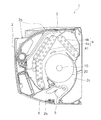
- Sectional drawing which shows the outline
- the perspective view which shows the outline
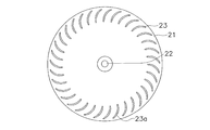
- the top view which shows an example of a structure of the end plate of an impeller.
- the perspective view which shows an example of a structure of the fan block of an impeller.
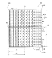
- the side view which shows an example of a structure of the fan block of an impeller.
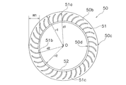
- the top view which shows an example of a structure of the support plate of a fan block.
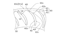
- Sectional drawing which shows an example of a structure of the auxiliary ring of a fan block.
- FIG. 6 is a partially enlarged plan view for explaining the configuration of the fan block shown in FIG. 5.
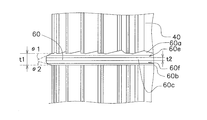
- FIG. 7 is a partially enlarged side view for explaining the configuration of the fan block shown in FIG. 6.
- the side view which shows the other example of a structure of the fan block of an impeller.
- the side view which shows the other example of a structure of the fan block of an impeller.
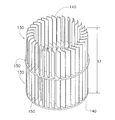
- the side view which shows the other example of a structure of an impeller.
- FIG. 1 is a diagram schematically showing a cross section of an indoor unit 1 of an air conditioner.
- the indoor unit 1 includes a main body casing 2, an air filter 3, an indoor heat exchanger 4, a cross flow fan 10, a vertical flap 5, and a horizontal flap 6.
- an air filter 3 is disposed on the top surface of the main body casing 2 on the top side downstream of the suction port 2 a so as to face the suction port 2 a.
- An indoor heat exchanger 4 is disposed further downstream of the air filter 3. All of the room air that passes through the suction port 2a and reaches the indoor heat exchanger 4 passes through the air filter 3 to remove dust.
- the indoor heat exchanger 4 is configured by connecting a front side heat exchanger 4a and a back side heat exchanger 4b so as to form an inverted V shape in a side view.
- the front-side heat exchanger 4 a When viewed from the top surface of the main casing 2, the front-side heat exchanger 4 a is disposed at a position substantially opposite to the front half of the suction port 2 a, and the rear-side heat exchanger 4 b is substantially opposite to the rear half. Is arranged.
- Both the front side heat exchanger 4a and the back side heat exchanger 4b are configured by arranging a large number of plate fins parallel to each other in the width direction of the indoor unit 1 and attaching them to the heat transfer tubes.
- a substantially cylindrical cross flow fan 10 extends long along the width direction of the main body casing 2, and is provided in parallel with the width direction of the main body casing 2 together with the indoor heat exchanger 4. Yes.
- the cross flow fan 10 includes an impeller 20 disposed in a space surrounded by an inverted V-shaped indoor heat exchanger 4 and a fan motor (not shown) for driving the impeller 20. ).
- the cross flow fan 10 rotates the impeller 20 in a direction A1 (clockwise) indicated by an arrow in FIG. 1 to generate an air flow.
- the blowout passage connected to the blowout port 2b downstream of the cross flow fan 10 is configured with a scroll member 2c on the back side.
- the scroll member 2c has substantially the same width as the opening of the air outlet 2b of the main casing 2 in a front view.
- the upper end of the scroll member 2c is located above the upper end of the cross flow fan 10, and is located at a position shifted to the back side from the central axis of the cylindrical cross flow fan 10 in a side view.
- the lower end of the scroll member 2c is connected to the open end of the air outlet 2b.
- FIG. 2 shows a schematic structure of the impeller 20 of the crossflow fan 10.
- the impeller 20 is configured, for example, by joining end plates 21 and 24 and three fan blocks 30.
- An end plate 21 is disposed at one end of the impeller 20, and has a metal rotation shaft 22 on the axis O.
- the end plate 24 with the blade 40 and the auxiliary ring 60 disposed at the other end of the impeller 20 is usually provided with a boss portion (not shown) connected to a fan motor shaft (not shown). Provided in the center.
- the end plate 24 disposed at the other end of the impeller 20 may have other configurations such as having a member coupled to a part of the fan motor and having a metal shaft at the center. is there.
- the rotating shaft 22 of the end plate 21 and the boss (or metal shaft) of the end plate 24 at the other end of the impeller 20 are supported, and the impeller 20 rotates around the axis O.
- the end plate 21 is the same as the conventional one. However, in order to apply the present invention, the structure of the end plate 21 does not have to be the same as the conventional one, and the structure of the end plate 21 can be changed as appropriate.
- Each fan block 30 includes a plurality of blades 40, an annular support plate 50, and an auxiliary ring 60.
- each fan block 30 has its own plurality of blades 40 welded to the support plate 50 or the end plate 21 of the adjacent fan block 30.
- FIG. 3 shows a process in which two adjacent fan blocks 30 are welded.
- the end plate 21 is first placed on the jig 103, the tip end portion 40 d of the blade 40 of the fan block 30 is fitted into the recess 23, and the horn 102 is applied to the support plate 50 of the fan block 30 to perform ultrasonic welding. Subsequently, as shown in FIG.
- the front end portion 40d of the blade 40 of the next fan block 30 is fitted into the concave portion 51 of the support plate 50 of the fan block 30 which has been welded, and the next series is similarly applied.
- the horn 102 is applied to the support plate 50 of the fan block 30 and ultrasonic welding is performed. At that time, the supporting plate 50 to be welded is chucked from the outer peripheral direction so as not to be misaligned. This operation is repeated, and finally, the horn 102 is applied to the end plate 24 with the blades 40 and welded. In order to position the blades 40 on the end plate 21 during such welding, the same number of recesses 23 as the blades 40 are formed in the end plate 21 as shown in FIG.
- each recess 23 has a planar shape slightly larger than the cross-sectional shape of each blade 40, each blade 40 is fitted and fitted into each recess 23.
- a step portion 23a is formed in order to position the end plate 21 and the fan block 30 in only one of the plurality of recesses 23, there is one in which a step portion 23a is formed.
- FIG. 5 is a perspective view showing one of the plurality of fan blocks 30 constituting the impeller 20 shown in FIG. 2, and FIG. 6 is a side view of the fan block 30.
- the fan block 30 shown in FIGS. 5 and 6 includes a plurality of blades 40, a support plate 50, and an auxiliary ring 60 that are integrally molded by injection molding or the like using a thermoplastic resin as a main material.
- the rotation direction of the fan block 30 is a direction A1 indicated by an arrow in FIG. (3-1) Blades
- the plurality of blades 40 extend from the first surface 50a of the annular support plate 50 in the longitudinal direction (direction along the axis O).
- the blade base 40 c is fixed to the first surface 50 a of the support plate 50, and the opposite side of the blade base 40 c in the longitudinal direction of the blade 40 is the blade tip 40 d.
- the length L1 of the blade 40 (the dimension from the blade base 40c to the blade tip 40d) is, for example, about 10 cm.
- the blade 40 has a suction surface 40f and a pressure surface e.
- a notch 40i is formed in the blade tip 40d.
- This notch 40i is used for positioning the two fan blocks 30 or the fan block 30 and the end plate 21, and the stepped portion 23a of the concave portion 23 of the end plate 21 described above or the fan block 30 described later. This is a portion that fits into the step 51 c of the recess 51. Since there is the notch 40i, each blade 40 and each recess 23 of the end plate 21 or each recess 51 of the fan block 30 can be made to correspond one-to-one.
- FIG. 7 shows a state in which the annular support plate 50 is viewed from the bottom surface, that is, a state viewed from the second surface 50b side. On the second surface 50b facing the first surface 50a of the support plate 50, a recess 51 into which the blade 40 is fitted is formed.
- each recess 51 has a planar shape slightly larger than the cross-sectional shape of each blade 40, when the two fan blocks 30 are overlapped, each blade 40 is fitted and fitted into each recess 51.
- the A ring-shaped convex portion 52 higher than the second surface 50 b is formed along the inner periphery of the support plate 50.
- the convex portion 52 is inclined obliquely on the outer peripheral side, and plays a role of guiding the blade 40 to the concave portion 51 when the two fan blocks 30 are overlaid.
- the outer periphery 51a of the recess 51 that contacts the outer end 40a of the blade 40 is inside the outer periphery 50c of the support plate 50, and the inner end 51b of the recess 51 that contacts the inner end 40b of the blade 40 is the inner periphery 50d of the support plate 50.
- the distance d1 from the center of the support plate 50 (a point on the axis O) to the outer periphery 51a of the recess 51 is the radius from the center of the support plate 50 to the outer periphery 50c. smaller than r1.
- the distance d2 from the center of the support plate 50 (a point on the axis O) to the inner end 51b of the recess 51 (the distance from the inner end 40b of the blade 40) is from the center of the support plate 50 to the inner periphery 50d. It is larger than the radius r2.
- the support plate 50 has a width W1 (radius r1-radius r2) of the support plate 50 that is a radial distance (distance) from the outer end 40a to the inner end 40b of the blades 40. It is set larger than d1 ⁇ distance d2).
- the auxiliary ring 60 is located in the middle portion of the blade 40 in the longitudinal direction, and is a distance of 60% of the dimension (the length L1 of the blade 40) from the blade base 40c to the blade tip 40d. Only a position away from the blade base 40c. In order to improve the strength of the cross flow fan 10 and facilitate the assembly process such as ultrasonic welding, the auxiliary ring 60 is disposed at a distance of 55% or more of the length L1 from the blade base 40c. It is preferable. However, the arrangement position of the auxiliary ring 60 does not necessarily need to be 55% or more of the length L1 from the blade base portion 40c, and may be located in the middle portion of the blade 40 in the longitudinal direction.
- FIG. 8 shows a cross-sectional shape of a portion where the auxiliary ring 60 and the blade 40 are joined.
- the cross section shown in FIG. 8 is a cross section that appears when cut along a plane perpendicular to the axis O.
- the auxiliary ring 60, the blade 40, and the support plate 50 are partially enlarged when viewed from the blade tip 40 d of the blade 40 toward the blade base 40 c.
- the auxiliary ring 60 mainly includes a ring part 61, a connection part 62, and a connection auxiliary part 63.
- the radius r3 of the outer periphery 61a of the ring part 61 is larger than the radius r1 of the outer periphery 51a of the support plate 50. Further, the radius r3 of the outer periphery 61a of the ring portion 61 is larger than the distance d1 from the center of the auxiliary ring 60 (a point on the axis O) to the outer end 40a of the blade 40. That is, the outer periphery 61 a of the ring portion 61 passes outside the outer ends 40 a of all the blades 40.
- the radius r4 of the inner periphery 61b of the ring portion 61 is larger than the radius r2 of the inner periphery 50d of the support plate 50 and slightly larger than the distance d1 to the outer end 40a of the blade 40.
- the inner circumference 61b passes near the outside of the outer end 40a of the blade 40.
- connection part 62 is formed in a triangular shape protruding inward from the ring part 61 when viewed in the direction of the axis O.
- the triangular connection portion 62 has three top portions 62a, 62b, and 62c, the side between the top portions 62a and 62b is connected to the ring portion 61, and the side between the top portions 62a and 62c is the suction surface of the blade 40. 40f.
- the connecting portion 62 is not connected to the pressure surface 40 e of the blade 40.
- the length L4 (the length from the top portion 62a to the top portion 62c) of the portion where the connecting portion 62 is connected to the suction surface 40f is shorter than one half of the chord length L3.
- connection auxiliary portion 63 is formed in the vicinity of the outer end 40a of the blade 40.
- the connection auxiliary portion 63 is a portion that fills the space between the outer end 40a of the blade 40, the connection portion 62, and the ring portion 61, and assists the connection of these three members.
- FIG. 10 shows an enlarged part of the auxiliary ring 60 as seen from the side.
- the auxiliary ring 60 has a first surface 60a on the blade tip 40d side, a second surface 60b on the blade base 40c side, an outer peripheral surface 60c, and an inner peripheral surface 60d.
- a curved surface 60e having a radius of curvature R1 is formed at a portion connecting the first surface 60a and the outer peripheral surface 60c
- a curved surface 60f having a radius of curvature R2 is formed at a portion connecting the second surface 60b and the outer peripheral surface 60c.
- the auxiliary ring 60 is thinner as it goes from the inner circumference side to the outer circumference side.
- the auxiliary ring 60 has a thickness t2 on the outer peripheral surface 60c smaller than a thickness t1 in the vicinity of the blade base 40c.
- the first surface 60a of the auxiliary ring 60 has an inclination angle ⁇ 1 that intersects a plane perpendicular to the axis 0 and a tilt angle ⁇ 2 that the second surface 60b intersects this perpendicular plane. Is set to The thickness t1 of the auxiliary ring 60 is set smaller than the thickness t3 of the support plate 50.
- the blade 40 has a large number of notches 40 g.
- a recess 40h is formed around each notch 40g.
- Each notch 40g is formed at the outer end 40a of each blade 40.
- the cut portion 40g has a delta shape when viewed from a direction perpendicular to the suction surface 40f of each blade 40, and extends toward the outer end 40a. Thereby, in a fan blowing area
- the distance d3 between the adjacent cut portions 40g is set to be the same between any adjacent cut portions 40g.
- the concave portion 40h has the smallest thickness at the V-shaped portion in contact with the cut portion 40g.
- the thickness of the V-shaped portion is substantially equal to the thickness of the outer end 40 a of the blade 40.
- Each concave portion 40h surrounds the cut portion 40g in a C shape, and is gently inclined from the suction surface 40f toward the cut portion 40g. In the recess 40h, there is no unevenness from the suction surface 40f toward the notch 40g, so noise is hardly generated. Further, since there is no step from the suction surface 40f toward the notch 40g, noise is hardly generated.
- the auxiliary ring 60 is disposed at a position where the notch 40g between the two notches 40g at the center of each blade 40 is not formed.
- (4) Modification (4-1) Although the case where one auxiliary ring 60 is provided in one fan block 30 has been described in the above embodiment, a plurality of auxiliary rings 60 may be provided in one fan block 30. (4-2) In the above embodiment, the case where the radius r3 of the outer periphery 61a of the ring portion 61 is larger than the radius r1 of the outer periphery 51a of the annular support plate 50 has been described. It may be set to be the same as the radius r1 of the 50 outer peripheries 51a.
- the said embodiment demonstrated the case where the shape of all the cut parts 40g of the fan block 30 was the same as FIG. 6 showed, you may vary the shape of a cut part.
- the shapes of the cut portions 40g and 40j can be made different.
- the pair of blades 401 and 402 having different shapes of the cut portions are configured to be continuously arranged (a configuration in which the blades 401 and the blades 402 appear alternately during one round of the fan block 30).
- the fan block 30 may be arranged in some places.
- the shape of the cut portion 40g and 40j is different from that of the cut portion 40g having a delta shape as shown in FIG. 11, whereas the cut portion 40j has a circular shape. It is a concept that includes not only different cases but also the same shape but different sizes.
- the shape of the recess 40h may be changed in accordance with the shape of the notches 40g and 40j, or Only the shape may be different between the blades 40 adjacent to each other.
- the arrangement pitch of all the cut portions 40g of the fan block 30 (the distance d3 between the cut portions 40g adjacent to each other) is the same has been described.
- the arrangement pitch of the notches may be varied.
- the distance d4 of the portion where the auxiliary ring 60 is disposed may be set larger than the distance d3 of the portion where the auxiliary ring 60 is not disposed.
- the distance from the portion where the auxiliary ring 60 is arranged to the notch 40g (approximately a half of the distance d4) is the same as that in FIG. 6 (approximately the half of the distance d3). It can be made longer than 1).
- mutual interference between the auxiliary ring 60 and the notch 40g can be reduced, and the effect of suppressing the decrease in wind speed at the ring 61 of the auxiliary ring 60 is enhanced.
- the arrangement intervals of the blades 40 are the same has been described. However, as illustrated in FIG. May be.
- a space between the blade 403 and the blade 404 is set to an arrangement interval L7 different from the arrangement intervals L4 and L5.
- the arrangement interval of the blades is a distance from the position of the center of gravity of one blade 403 to the position of the center of gravity of the adjacent blade 404 when viewed in a cross section perpendicular to the central axis O.
- the blade 40 When the arrangement interval of the blades 40 is the same, the blade 40 is located at the same position every time (tf / nf) obtained by dividing the time tf required for the fan block 30 to make one revolution by the number nf of the blades 40 of the fan block 30. The situation that exists in is repeated. Thus, when the movement of the blades 40 is performed regularly, noise with a frequency corresponding to the value of nf / tf is likely to occur. If the arrangement intervals L5 and L6 of the blades 403, 404, 405, and 406 are made different as shown in FIG. And the regularity of movement of the blades 40 is disturbed. Thereby, the vibration of the air which arises by the movement of the blade
- wing 40 of the fan block 30 adjacent to each other is arrange
- the fan block blades adjacent to each other need not be aligned.
- the fan blocks 310 and 320 are ultrasonically welded at a position shifted by a predetermined angle ⁇ 3 so as not to be aligned in a straight line, such as the blades 407 and 408 of the adjacent fan blocks 310 and 320 shown in FIG. .
- the ring portion 61 of the auxiliary ring 60 is located outside the outer end 40a of the plurality of blades 40, 401 to 408, located in the middle portion in the longitudinal direction of the plurality of blades 40, 401 to 408.
- the plurality of connecting portions 62 of the auxiliary ring 60 extend from the ring portion 61 to the adjacent blades of the plurality of blades 40 and 401 to 408, and are joined to the blades 40 and 401 to 408 between the adjacent blades.
- a plurality of cut portions 40g and 40j are formed in 40a. In other words, the space between adjacent blades is sandwiched between the pressure surface 40e of one blade 40, 401-408 of the plurality of blades 40, 401-408 and the negative pressure surface 40f of the adjacent blade 40, 401-408. It is a designated area.
- the auxiliary ring 60 is joined to the blades 40 and 401 to 408 at the connecting portion 62 that extends only between the adjacent blades, thereby suppressing the flow path pressure loss.
- the annular ring portion 61 bundles the plurality of blades 40 at the intermediate portion in the longitudinal direction of the plurality of blades 40, 401 to 408, thereby including the annular support plate 50 and the plurality of blades 40, 401 to 408.
- the strength of the fan blocks 30, 310, 320 is reinforced.
- the auxiliary ring 60 is joined to the blades 40 and 401 to 408 at the connecting portion 62 that extends only between the adjacent blades, thereby suppressing the flow path pressure loss.
- the annular ring portion 61 bundles the plurality of blades 40, 401 to 408 at the longitudinal intermediate portions of the plurality of blades 40, 401 to 408, whereby the annular support plate 50 and the plurality of blades 40, 401 are combined.
- the strength of the fan blocks 30, 310, 320 including ⁇ 408 is reinforced.
- noise such as wind noise increases because the blades 40, 401 to 408 of the fan blocks 30, 310, and 320 are lengthened, and the noise is generated at the outer ends 40a of the blades 40, 401 to 408. It can suppress by forming 40g and 40j.
- the structure joined by the support plate 150 can be considered.
- the structure of the support plate 150 is the same as that of the support plate 50 described above.
- the strength when the impeller is configured is almost the same.
- the flow path loss of the two fan blocks 130 becomes larger than in the case of the auxiliary ring 60.
- an increase in the cost for assembly can be considered due to an increase in the number of steps for joining the two fan blocks 130.
- the said embodiment demonstrated the case where the support plate 50 was circular, even if a support plate is disk shape, it can form similarly to the case where it is circular, and uses a disk-shaped support plate. Even in this case, the same effect as that obtained when the annular support plate 50 is used can be obtained.
- the auxiliary ring 60 is disposed at a position where the cut portions 40g and 40j of the plurality of blades 40 and 401 to 408 are not formed.
- the auxiliary ring 60 and the plurality of blades 40, 401 to 408 are formed of resin, and the auxiliary ring 60 is integrated with the plurality of blades 40, 401 to 408 by injection molding or the like. Molded.
- the support plate 50 is also formed of resin, and is molded integrally with the auxiliary ring 60 and the plurality of blades 40, 401 to 408 by injection molding or the like simultaneously with the plurality of blades 40, 401 to 408 and the auxiliary ring 60. Has been. Therefore, the cost reduction effect by reducing the assembly man-hour is further increased.
- the auxiliary ring 60 becomes thinner as the thickness of the ring portion 61 goes from the inner peripheral side to the outer peripheral side. That is, the inner thickness t1 is larger than the outer thickness t2. Therefore, the fluid loss of air in the auxiliary ring 60 can be reduced, and the air blowing characteristics can be improved. In addition, it is preferable that the thickness of the auxiliary ring 60 decreases from the connecting portion 62 to the ring portion 61 as it goes to the outer peripheral side. Also in this case, the air blowing characteristics can be further improved. Further, since the auxiliary ring 60 is thinner on the outer peripheral side than on the inner peripheral side, the fan block 30 of the cross flow fan 10 can be easily removed from the mold during injection molding.
- connection portion 62 is formed in a triangular shape protruding inward from the ring portion 61.
- One side of the triangular connection part 62 (the side between the top part 62a and the top part 62c) is joined to the suction surface 40f of the blades 40, 401 to 408. Since one side of the triangular connecting portion 62 is joined to the suction surface 40f of the blades 40, 401 to 408, the joining portion can be enlarged relative to the area of the connecting portion 62.
- one of the vertices is on the pressure surface side of the other blade, the flow path loss increased by the connecting portion can be suppressed low.
- connection portion 60 the sides between the top portions 62a, 62b, and 62c are substantially linear, but each side may be slightly uneven.
- the plurality of blades 40, 401, 404 to 408 have a delta shape in which the shape of the cut portion 40g extends toward the outer end.
- a delta shape for example, air flows more smoothly than when the shape is U-shaped, and vibration of the air at the notch 40g is suppressed. As a result, the effect of reducing wind noise is improved.
Landscapes
- Engineering & Computer Science (AREA)
- Mechanical Engineering (AREA)
- General Engineering & Computer Science (AREA)
- Structures Of Non-Positive Displacement Pumps (AREA)
Priority Applications (2)
| Application Number | Priority Date | Filing Date | Title |
|---|---|---|---|
| CN201380046041.8A CN104603466A (zh) | 2012-09-04 | 2013-08-29 | 横流风扇 |
| EP13836035.9A EP2894345A4 (fr) | 2012-09-04 | 2013-08-29 | Ventilateur à flux transversal |
Applications Claiming Priority (6)
| Application Number | Priority Date | Filing Date | Title |
|---|---|---|---|
| JP2012194255A JP5590081B2 (ja) | 2012-09-04 | 2012-09-04 | クロスフローファン |
| JP2012-194256 | 2012-09-04 | ||
| JP2012-194255 | 2012-09-04 | ||
| JP2012194256A JP5704139B2 (ja) | 2012-09-04 | 2012-09-04 | クロスフローファン |
| JP2012-216122 | 2012-09-28 | ||
| JP2012216122A JP5590088B2 (ja) | 2012-09-28 | 2012-09-28 | クロスフローファン |
Publications (1)
| Publication Number | Publication Date |
|---|---|
| WO2014038467A1 true WO2014038467A1 (fr) | 2014-03-13 |
Family
ID=50237079
Family Applications (1)
| Application Number | Title | Priority Date | Filing Date |
|---|---|---|---|
| PCT/JP2013/073145 Ceased WO2014038467A1 (fr) | 2012-09-04 | 2013-08-29 | Ventilateur à flux transversal |
Country Status (3)
| Country | Link |
|---|---|
| EP (1) | EP2894345A4 (fr) |
| CN (1) | CN104603466A (fr) |
| WO (1) | WO2014038467A1 (fr) |
Families Citing this family (3)
| Publication number | Priority date | Publication date | Assignee | Title |
|---|---|---|---|---|
| KR102203939B1 (ko) * | 2014-01-06 | 2021-01-18 | 삼성전자주식회사 | 가이드 블레이드 및 이를 갖춘 공기조화기 |
| CN109538514A (zh) * | 2019-01-21 | 2019-03-29 | 湖北工程职业学院 | 一种减震降噪的横流风机 |
| CN116265761B (zh) * | 2021-12-16 | 2026-01-23 | 宁波奥克斯电气有限公司 | 斜扭贯流风叶和空调器 |
Citations (7)
| Publication number | Priority date | Publication date | Assignee | Title |
|---|---|---|---|---|
| JPS56136192U (fr) * | 1980-03-14 | 1981-10-15 | ||
| JPH03229991A (ja) * | 1990-02-05 | 1991-10-11 | Matsushita Electric Ind Co Ltd | 横断流送風機 |
| JPH0587086A (ja) | 1991-09-05 | 1993-04-06 | Sanko Gosei Kk | 筒状羽根車 |
| JP2001263285A (ja) * | 2000-03-21 | 2001-09-26 | Mitsubishi Electric Corp | 貫流送風機および空気調和機 |
| JP2008002378A (ja) * | 2006-06-23 | 2008-01-10 | Daikin Ind Ltd | 多翼ファン |
| JP2009293616A (ja) * | 2008-05-09 | 2009-12-17 | Daikin Ind Ltd | クロスフローファン及びこれを備えた空気調和機 |
| JP2010236540A (ja) * | 2009-03-10 | 2010-10-21 | Daikin Ind Ltd | クロスフローファン及びこれを備えた空気調和機 |
Family Cites Families (9)
| Publication number | Priority date | Publication date | Assignee | Title |
|---|---|---|---|---|
| GB980623A (en) * | 1960-02-12 | 1965-01-13 | Firth Cleveland Ltd | Improvements relating to cross-flow blowers |
| GB986222A (en) * | 1960-02-15 | 1965-03-17 | Firth Cleveland Ltd | Improvements relating to bladed rotors for flow machines and apparatus for making such rotors |
| JPS51154411U (fr) * | 1975-06-04 | 1976-12-09 | ||
| JPS5274105A (en) * | 1975-12-17 | 1977-06-21 | Hitachi Ltd | Straight blow fan and method of manufacture of same |
| JP3107711B2 (ja) * | 1994-08-09 | 2000-11-13 | 株式会社東芝 | 横流ファン |
| JP4432865B2 (ja) * | 2004-09-30 | 2010-03-17 | ダイキン工業株式会社 | 送風機の羽根車およびそれを用いた空気調和機 |
| JP3995010B2 (ja) * | 2005-09-28 | 2007-10-24 | ダイキン工業株式会社 | 多翼送風機の羽根車及びその製造方法 |
| JP4973249B2 (ja) * | 2006-03-31 | 2012-07-11 | ダイキン工業株式会社 | 多翼ファン |
| JP4775867B1 (ja) * | 2010-03-15 | 2011-09-21 | シャープ株式会社 | ファン、成型用金型および流体送り装置 |
-
2013
- 2013-08-29 WO PCT/JP2013/073145 patent/WO2014038467A1/fr not_active Ceased
- 2013-08-29 CN CN201380046041.8A patent/CN104603466A/zh active Pending
- 2013-08-29 EP EP13836035.9A patent/EP2894345A4/fr not_active Withdrawn
Patent Citations (7)
| Publication number | Priority date | Publication date | Assignee | Title |
|---|---|---|---|---|
| JPS56136192U (fr) * | 1980-03-14 | 1981-10-15 | ||
| JPH03229991A (ja) * | 1990-02-05 | 1991-10-11 | Matsushita Electric Ind Co Ltd | 横断流送風機 |
| JPH0587086A (ja) | 1991-09-05 | 1993-04-06 | Sanko Gosei Kk | 筒状羽根車 |
| JP2001263285A (ja) * | 2000-03-21 | 2001-09-26 | Mitsubishi Electric Corp | 貫流送風機および空気調和機 |
| JP2008002378A (ja) * | 2006-06-23 | 2008-01-10 | Daikin Ind Ltd | 多翼ファン |
| JP2009293616A (ja) * | 2008-05-09 | 2009-12-17 | Daikin Ind Ltd | クロスフローファン及びこれを備えた空気調和機 |
| JP2010236540A (ja) * | 2009-03-10 | 2010-10-21 | Daikin Ind Ltd | クロスフローファン及びこれを備えた空気調和機 |
Non-Patent Citations (1)
| Title |
|---|
| See also references of EP2894345A4 * |
Also Published As
| Publication number | Publication date |
|---|---|
| CN104603466A (zh) | 2015-05-06 |
| EP2894345A1 (fr) | 2015-07-15 |
| EP2894345A4 (fr) | 2015-08-12 |
Similar Documents
| Publication | Publication Date | Title |
|---|---|---|
| KR101547799B1 (ko) | 크로스 플로우 팬 | |
| EP1933040B1 (fr) | Turboventilateur et climatiseur | |
| CN108350893B (zh) | 横流风扇 | |
| CN102187100B (zh) | 贯流风扇、送风机和叶轮成形机 | |
| CN104603465B (zh) | 横流风扇 | |
| JP5187353B2 (ja) | 貫流ファン及びこれを備えた空気調和機 | |
| WO2014038467A1 (fr) | Ventilateur à flux transversal | |
| JP3668782B2 (ja) | 送風ファンおよびその製造方法 | |
| JP5664809B2 (ja) | クロスフローファン | |
| JP5041446B2 (ja) | 貫流ファン、送風機および羽根車の成形機 | |
| JP5590088B2 (ja) | クロスフローファン | |
| JP5030115B2 (ja) | 貫流ファン、送風機および羽根車の成形機 |
Legal Events
| Date | Code | Title | Description |
|---|---|---|---|
| 121 | Ep: the epo has been informed by wipo that ep was designated in this application |
Ref document number: 13836035 Country of ref document: EP Kind code of ref document: A1 |
|
| NENP | Non-entry into the national phase |
Ref country code: DE |
|
| REEP | Request for entry into the european phase |
Ref document number: 2013836035 Country of ref document: EP |
|
| WWE | Wipo information: entry into national phase |
Ref document number: 2013836035 Country of ref document: EP |