WO2014042012A1 - 空調室内機 - Google Patents
空調室内機 Download PDFInfo
- Publication number
- WO2014042012A1 WO2014042012A1 PCT/JP2013/073149 JP2013073149W WO2014042012A1 WO 2014042012 A1 WO2014042012 A1 WO 2014042012A1 JP 2013073149 W JP2013073149 W JP 2013073149W WO 2014042012 A1 WO2014042012 A1 WO 2014042012A1
- Authority
- WO
- WIPO (PCT)
- Prior art keywords
- coanda
- air
- blade
- airflow
- wind direction
- Prior art date
- Legal status (The legal status is an assumption and is not a legal conclusion. Google has not performed a legal analysis and makes no representation as to the accuracy of the status listed.)
- Ceased
Links
Images










Classifications
-
- F—MECHANICAL ENGINEERING; LIGHTING; HEATING; WEAPONS; BLASTING
- F24—HEATING; RANGES; VENTILATING
- F24F—AIR-CONDITIONING; AIR-HUMIDIFICATION; VENTILATION; USE OF AIR CURRENTS FOR SCREENING
- F24F1/00—Room units for air-conditioning, e.g. separate or self-contained units or units receiving primary air from a central station
- F24F1/0007—Indoor units, e.g. fan coil units
- F24F1/0011—Indoor units, e.g. fan coil units characterised by air outlets
-
- F—MECHANICAL ENGINEERING; LIGHTING; HEATING; WEAPONS; BLASTING
- F24—HEATING; RANGES; VENTILATING
- F24F—AIR-CONDITIONING; AIR-HUMIDIFICATION; VENTILATION; USE OF AIR CURRENTS FOR SCREENING
- F24F1/00—Room units for air-conditioning, e.g. separate or self-contained units or units receiving primary air from a central station
- F24F1/0007—Indoor units, e.g. fan coil units
- F24F1/0043—Indoor units, e.g. fan coil units characterised by mounting arrangements
- F24F1/0057—Indoor units, e.g. fan coil units characterised by mounting arrangements mounted in or on a wall
-
- F—MECHANICAL ENGINEERING; LIGHTING; HEATING; WEAPONS; BLASTING
- F24—HEATING; RANGES; VENTILATING
- F24F—AIR-CONDITIONING; AIR-HUMIDIFICATION; VENTILATION; USE OF AIR CURRENTS FOR SCREENING
- F24F11/00—Control or safety arrangements
- F24F11/70—Control systems characterised by their outputs; Constructional details thereof
- F24F11/72—Control systems characterised by their outputs; Constructional details thereof for controlling the supply of treated air, e.g. its pressure
- F24F11/79—Control systems characterised by their outputs; Constructional details thereof for controlling the supply of treated air, e.g. its pressure for controlling the direction of the supplied air
-
- F—MECHANICAL ENGINEERING; LIGHTING; HEATING; WEAPONS; BLASTING
- F24—HEATING; RANGES; VENTILATING
- F24F—AIR-CONDITIONING; AIR-HUMIDIFICATION; VENTILATION; USE OF AIR CURRENTS FOR SCREENING
- F24F13/00—Details common to, or for air-conditioning, air-humidification, ventilation or use of air currents for screening
- F24F13/08—Air-flow control members, e.g. louvres, grilles, flaps or guide plates
- F24F13/10—Air-flow control members, e.g. louvres, grilles, flaps or guide plates movable, e.g. dampers
- F24F13/14—Air-flow control members, e.g. louvres, grilles, flaps or guide plates movable, e.g. dampers built up of tilting members, e.g. louvre
- F24F13/1413—Air-flow control members, e.g. louvres, grilles, flaps or guide plates movable, e.g. dampers built up of tilting members, e.g. louvre using more than one tilting member, e.g. with several pivoting blades
-
- F—MECHANICAL ENGINEERING; LIGHTING; HEATING; WEAPONS; BLASTING
- F24—HEATING; RANGES; VENTILATING
- F24F—AIR-CONDITIONING; AIR-HUMIDIFICATION; VENTILATION; USE OF AIR CURRENTS FOR SCREENING
- F24F2221/00—Details or features not otherwise provided for
- F24F2221/28—Details or features not otherwise provided for using the Coanda effect
Definitions
- the present invention relates to an air conditioning indoor unit, and more particularly to an air conditioning indoor unit that uses the Coanda effect.
- the subject of this invention is providing the air-conditioning indoor unit which can implement
- An air conditioner indoor unit is an air conditioner indoor unit that generates a fluctuating air flow by changing the wind direction of conditioned air blown out from a blower outlet, and includes a Coanda blade and a control unit. ing.
- the Coanda blade is provided in the vicinity of the air outlet, and guides the conditioned air into a predetermined direction as a Coanda airflow along its lower surface by the Coanda effect.
- the control unit controls the fluctuation airflow of the conditioned air.
- control unit controls the operation of the Coanda blade during fluctuation airflow control, and executes a first mode including a Coanda generation state in which the Coanda airflow is generated and a Coanda non-generation state in which the Coanda airflow is not generated.
- the Coanda blades change the flow of conditioned air instantaneously into a Coanda airflow directed in a predetermined direction by the Coanda effect. In other words, when the Coanda effect is eliminated, the Coanda airflow instantaneously switches to the original flow.
- the conditioned air hits the resident, the conditioned air does not hit the resident at the same time as the Coanda airflow is generated, and the conditioned air hits the resident at the same time as the Coanda effect is eliminated.
- this air conditioning indoor unit when the fluctuation airflow control is performed, the flow of wind is diversified by suddenly generating a Coanda airflow, so that conditioned air closer to natural wind can be provided to the occupant.
- An air conditioner indoor unit is an air conditioner indoor unit that generates a fluctuating air flow by changing the wind direction of conditioned air blown out from a blower outlet, and includes a Coanda blade and a control unit. ing.
- the Coanda blade is provided in the vicinity of the air outlet, and guides the conditioned air in a predetermined direction into a Coanda airflow along its lower surface by the Coanda effect.
- the control unit controls the fluctuation airflow by changing the wind direction change pattern of the conditioned air. Further, at least the first mode and the second mode are preset in the control unit as modes that can be executed.
- the first mode is a mode including a Coanda generation state in which the operation of the Coanda blade is controlled to generate a Coanda airflow and a Coanda non-generation state in which the Coanda airflow is not generated during fluctuation airflow control.
- the second mode is a mode in which a Coanda airflow is not always generated during fluctuation airflow control. Furthermore, a control part mixes the time slot
- the Coanda blades change the flow of conditioned air instantaneously into a Coanda airflow directed in a predetermined direction by the Coanda effect.
- the Coanda airflow instantaneously switches to the original flow.
- the conditioned air hits the resident, the conditioned air does not hit the resident at the same time as the Coanda airflow is generated, and the conditioned air hits the resident at the same time as the Coanda effect is eliminated.
- the flow of wind is diversified by mixing the time zone in which the first mode is executed and the time zone in which the second mode is executed. Can be provided to residents.
- the air conditioning indoor unit according to the third aspect of the present invention is the air conditioning indoor unit according to the first aspect or the second aspect, and further includes a wind direction adjusting blade that changes a blowing angle of the conditioned air with respect to a horizontal plane.
- the control unit controls the fluctuation airflow using one or both of the wind direction adjusting blade and the Coanda blade.
- This air conditioner indoor unit can realize three types of fluctuation airflow, including fluctuation airflow caused only by wind direction adjustment blades, fluctuation airflow caused only by Coanda blades, and fluctuation airflow caused by wind direction adjustment blades and Coanda blades. On the other hand, it is possible to provide a fluctuating airflow that is varied.
- the air conditioning indoor unit is the air conditioning indoor unit according to the third aspect, wherein the fluctuation airflow control includes an A mode and a B mode.
- the A mode the airflow is generated by swinging the wind direction adjusting blade and the Coanda blade.
- the B mode only the wind direction adjusting blade is swung to generate a fluctuating air current.
- the fluctuation airflow that gradually approaches and gradually moves away from the resident is instantaneously adsorbed on the lower surface of the Coanda blade by the swing of the Coanda blade and becomes a Coanda airflow and is not suitable for the resident. The state where the Coanda effect is eliminated and the state toward the resident is repeated.
- the conditioned air is swung up and down by the wind direction adjusting blades, and becomes a fluctuating air flow that gradually approaches and gradually moves away from the occupant. That is, by mixing the A mode and the B mode, it is possible to realize a fluctuation air flow accompanied by “unexpected wind” and a fluctuation air flow accompanied by “unexpected wind”.
- An air conditioning indoor unit is the air conditioning indoor unit according to the fourth aspect, wherein the fluctuation airflow control further includes a C mode in which only the Coanda blade is oscillated to generate a fluctuation airflow. .
- the C mode when the direction of the conditioned air is constant, the Coanda vane swings and is instantaneously adsorbed on the lower surface of the Coanda vane to become a Coanda airflow and is not suitable for the resident. Is canceled and the state toward the resident is repeated. That is, a certain “unexpected wind” can be generated.
- An air conditioning indoor unit is the air conditioning indoor unit according to the first aspect or the second aspect, and the control unit changes the air volume of the conditioned air during fluctuation airflow control.
- conditioned air becomes an airflow that is closer to natural wind by changing the air volume in addition to the wind direction, so that a comfortable air-conditioned space can be provided to the occupant.
- An air conditioning indoor unit is the air conditioning indoor unit according to the sixth aspect, wherein the control unit changes the air volume of the conditioned air to a predetermined air volume at least during a time period in which the Coanda air current is generated.
- “unexpected wind” has no effect unless it reaches the residents. In other words, if the air volume in the time zone in which the Coanda air current is generated is reduced, the conditioned air at the moment when the Coanda effect is canceled does not reach the resident due to the air volume reduction and does not become an “unexpected wind”.
- the conditioned air volume is changed to a predetermined volume at least during the time period in which the Coanda flow is generated, and the conditioned air at the moment when the Coanda effect is eliminated maintains the predetermined volume. Can be realized.
- the flow of the wind is diversified by suddenly generating the Coanda airflow during the fluctuation airflow control, so that conditioned air closer to natural wind is provided to the occupant. be able to.
- the flow of wind diversifies by mixing the time zone for executing the first mode and the time zone for executing the second mode at the time of fluctuation airflow control. It is possible to provide residents with conditioned air that is closer to natural wind.
- the air conditioner indoor unit In the air conditioner indoor unit according to the third aspect of the present invention, three types of fluctuation airflow are realized, including fluctuation airflow caused only by the wind direction adjustment blade, fluctuation airflow caused only by the Coanda blade, and fluctuation airflow caused by the wind direction adjustment blade and the Coanda blade. It is possible to provide a fluctuating air flow that is varied to residents.
- the air-conditioning indoor unit by mixing the A mode and the B mode, a fluctuation air flow accompanied by “unexpected wind” and a fluctuation air flow accompanied by “unexpected wind” are realized. be able to.
- the air conditioning indoor unit pertaining to the fifth aspect of the present invention in the C mode, when the direction of the conditioned air is constant, the Coanda blade swings and is instantaneously adsorbed on the lower surface of the Coanda blade, resulting in a Coanda airflow. The state where it disappears and the state where the Coanda effect is canceled and the occupant is directed again are repeated. That is, a certain “unexpected wind” can be generated.
- the conditioned air becomes an airflow that is closer to natural wind by changing the air volume in addition to the wind direction, so that a comfortable air-conditioned space can be provided to the occupant.
- the conditioned air volume is changed to the predetermined air volume, and the conditioned air at the moment when the Coanda effect is eliminated maintains the predetermined air volume.
- the “unexpected wind” can be realized.
- the conceptual diagram which shows the direction of conditioned air, and the direction of Coanda airflow.
- the conceptual diagram showing an example of the opening angle of a wind direction adjustment blade
- wing consist, and the internal angle which the tangent of the terminal F of a scroll and a wind direction adjustment blade
- wing consist.
- the side view of the air-conditioning indoor unit installation space which shows the wind direction of Coanda airflow when the attitude
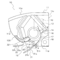
- FIG. 1 is a cross-sectional view of the air conditioning indoor unit 10 when operation is stopped according to an embodiment of the present invention.
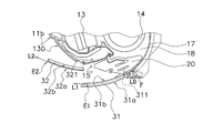
- FIG. 2 is a cross-sectional view of the air conditioning indoor unit 10 during operation. 1 and 2, the air conditioning indoor unit 10 is a wall-hanging type, and a main body casing 11, an indoor heat exchanger 13, an indoor fan 14, a bottom frame 16, and a control unit 40 are mounted thereon.
- the main body casing 11 has a top surface portion 11a, a front panel 11b, a back plate 11c, and a lower horizontal plate 11d, and houses an indoor heat exchanger 13, an indoor fan 14, a bottom frame 16, and a control unit 40 therein. .
- the top surface part 11a is located in the upper part of the main body casing 11, and the inlet (not shown) is provided in the front part of the top surface part 11a.
- the front panel 11b constitutes the front part of the indoor unit, and has a flat shape without a suction port. Further, the upper end of the front panel 11b is rotatably supported by the top surface portion 11a, and can operate in a hinged manner.
- the indoor heat exchanger 13 and the indoor fan 14 are attached to the bottom frame 16.
- the indoor heat exchanger 13 exchanges heat with the passing air.
- the indoor heat exchanger 13 has an inverted V-shape in which both ends are bent downward in a side view, and the indoor fan 14 is located below the indoor heat exchanger 13.
- the indoor fan 14 is a cross-flow fan, blows air taken in from the room against the indoor heat exchanger 13 and then blows it into the room.
- An air outlet 15 is provided at the lower part of the main body casing 11.
- a wind direction adjusting blade 31 that changes the direction of conditioned air blown from the blower outlet 15 is rotatably attached to the blower outlet 15.
- the wind direction adjusting blade 31 is driven by a motor (not shown) and can change the direction of the conditioned air, and can also open and close the air outlet 15.
- the wind direction adjusting blade 31 can take a plurality of postures having different inclination angles.
- a Coanda blade 32 is provided in the vicinity of the air outlet 15.
- the Coanda blade 32 can take a posture inclined in the front-rear direction by a motor (not shown), and is accommodated in the accommodating portion 130 provided in the front panel 11b when the operation is stopped.
- the Coanda blade 32 can take a plurality of postures having different inclination angles. Further, the air outlet 15 is connected to the inside of the main body casing 11 by the air outlet channel 18. The blowout channel 18 is formed along the scroll 17 of the bottom frame 16 from the blowout port 15.
- the indoor air is sucked into the indoor fan 14 through the suction port and the indoor heat exchanger 13 by the operation of the indoor fan 14, and blown out from the blower outlet 15 through the blowout passage 18 from the indoor fan 14.
- the control unit 40 is located on the right side of the indoor heat exchanger 13 and the indoor fan 14 when the main body casing 11 is viewed from the front panel 11b, and controls the rotational speed of the indoor fan 14, the wind direction adjusting blade 31 and the Coanda blade 32. Perform motion control.
- the depth of the depression in this region is set so as to match the thickness dimension of the Coanda blade 32, and constitutes a housing portion 130 in which the Coanda blade 32 is housed.
- the surface of the accommodating part 130 is also a gentle circular curved surface.
- the blower outlet 15 is formed in the lower part of the main body casing 11, and is a rectangular opening which makes a horizontal direction (direction orthogonal to the paper surface of FIG. 1) a long side.
- the lower end of the blower outlet 15 is in contact with the front edge of the lower horizontal plate 11d, and the virtual plane connecting the lower end and the upper end of the blower outlet 15 is inclined forward and upward.
- Scroll 17 The scroll 17 is a partition wall curved so as to face the indoor fan 14 and is a part of the bottom frame 16.
- the end F of the scroll 17 reaches the vicinity of the periphery of the air outlet 15.
- the air passing through the blowout flow path 18 travels along the scroll 17 and is sent in the tangential direction of the end F of the scroll 17. Therefore, if there is no wind direction adjusting blade 31 at the air outlet 15, the air direction of the conditioned air blown out from the air outlet 15 is a direction substantially along the tangent L 0 of the terminal end F of the scroll 17.
- the vertical wind direction adjusting plate 20 includes a plurality of blade pieces 201 and a connecting rod 203 that connects the plurality of blade pieces 201. Further, the vertical air direction adjusting plate 20 is disposed nearer the indoor fan 14 than the air direction adjusting blades 31 in the blowout flow path 18. The plurality of blade pieces 201 swing left and right around a state perpendicular to the longitudinal direction as the connecting rod 203 horizontally reciprocates along the longitudinal direction of the outlet 15. The connecting rod 203 is horizontally reciprocated by a motor (not shown). (2-5) Wind direction adjusting blade 31 The wind direction adjusting blade 31 has an area that can block the air outlet 15.
- the outer side surface 31 a is finished to have a gentle circular curved surface that protrudes outwardly as if it is an extension of the curved surface of the front panel 11 b. Further, the inner side surface 31b (see FIG. 2) of the wind direction adjusting blade 31 also forms an arcuate curved surface substantially parallel to the outer surface.
- the wind direction adjusting blade 31 has a rotation shaft 311 at the lower end.
- the rotating shaft 311 is connected to the rotating shaft of a stepping motor (not shown) fixed to the main body casing 11 in the vicinity of the lower end of the air outlet 15.
- the rotation shaft 311 rotates counterclockwise when viewed from the front in FIG. 1, so that the upper end of the airflow direction adjusting blade 31 moves away from the upper end side of the outlet 15 to open the outlet 15.
- the rotation shaft 311 rotates in the clockwise direction in FIG. 1, the upper end of the wind direction adjusting blade 31 operates so as to approach the upper end side of the outlet 15 to close the outlet 15.
- the conditioned air blown out from the air outlet 15 flows substantially along the inner side surface 31 b of the airflow direction adjusting blade 31.
- the conditioned air blown out substantially along the tangential direction of the terminal end F of the scroll 17 has its wind direction changed slightly upward by the wind direction adjusting blade 31.
- the Coanda blade 32 is stored in the storage unit 130 while the air-conditioning operation is stopped or in an operation in the normal blowing mode described later.
- the Coanda blade 32 moves away from the accommodating portion 130 by rotating.
- the rotation shaft 321 of the Coanda blade 32 is provided in the vicinity of the lower end of the housing portion 130 and inside the main body casing 11 (a position above the upper wall of the blowout flow path 18).
- the rotating shaft 321 is connected with a predetermined interval. Therefore, as the rotation shaft 321 rotates and the Coanda blade 32 moves away from the housing portion 130 of the front surface of the indoor unit, the height position of the lower end of the Coanda blade 32 rotates so as to become lower.
- the accommodating portion 130 is provided outside the air passage, and the entire Coanda blade 32 is accommodated outside the air passage when being accommodated.
- the rest may be accommodated in the air passage (for example, the upper wall portion of the air passage).
- the rotating shaft 321 rotates counterclockwise in the front view of FIG. 1, the upper and lower ends of the Coanda blades 32 are separated from the housing portion 130 while drawing an arc.
- the shortest distance between the accommodation unit 130 on the front surface of the indoor unit is larger than the shortest distance between the lower end and the accommodation unit 130. That is, the Coanda blade 32 is controlled so as to move away from the front surface of the indoor unit as it goes forward.
- the rotation shaft 321 rotates in the clockwise direction in the front view of FIG. 1
- the Coanda blade 32 approaches the storage unit 130 and is finally stored in the storage unit 130.
- the operating state of the Coanda blade 32 includes a state where the Coanda blade 32 is housed in the storage unit 130, a posture rotated and tilted forward and upward, a posture rotated and substantially horizontal, and a posture rotated and tilted forward and downward. is there.
- the outer surface 32a of the Coanda blade 32 is finished to a gentle circular curved surface that protrudes outwardly as if it is an extension of the gentle circular curved surface of the front panel 11b.
- the inner side surface 32 b of the Coanda blade 32 is finished to have an arcuate curved surface that follows the surface of the housing portion 130.
- the dimension in the longitudinal direction of the Coanda blade 32 is set to be equal to or larger than the dimension in the longitudinal direction of the wind direction adjusting blade 31. This is because all the conditioned air whose direction is adjusted by the wind direction adjusting blade 31 is received by the Coanda blade 32, and its purpose is to prevent the conditioned air from the side of the Coanda blade 32 from short-circuiting.
- Controlling the direction of conditioned air The air conditioning indoor unit of the present embodiment, as means for controlling the direction of conditioned air, is a normal blowing mode in which only the wind direction adjusting blade 31 is rotated to adjust the direction of conditioned air, and the wind direction.
- the adjustment vane 31 and the Coanda vane 32 are rotated, and the Coanda effect utilization mode in which the conditioned air is made into a Coanda airflow along the outer surface 32a of the Coanda vane 32 by the Coanda effect is provided. Since the postures of the wind direction adjusting blade 31 and the Coanda blade 32 change for each air blowing direction in each mode, each posture will be described with reference to the drawings. It should be noted that the blowing direction can be selected by the user via a remote controller or the like. It is also possible to control the mode change and the blowing direction to be automatically changed.
- FIG. 3A is a side view of the wind direction adjusting blade 31 and the Coanda blade 32 when the conditioned air is normally forward blown.
- the control unit 40 rotates the wind direction adjusting blade 31 to a position where the inner side surface 31b of the wind direction adjusting blade 31 becomes substantially horizontal.
- wing 31 has comprised the circular arc curved surface like this embodiment, the wind direction adjustment blade
- FIG. 3B is a side view of the wind direction adjusting blade 31 and the Coanda blade 32 when the conditioned air is normally forward down blown.
- the control unit 40 rotates the wind direction adjusting blade 31 until the tangent at the front end E1 of the inner side surface 31b of the wind direction adjusting blade 31 becomes lower than the horizontal. As a result, the conditioned air is in a front lower blowing state.
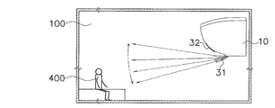
- FIG. 6A is a side view of the air conditioning indoor unit installation space showing the wind direction of the conditioned air by the vertical swing of the wind direction adjusting blade 31.
- the wind direction adjustment as shown in FIG. 6A is a wind direction adjustment by a so-called auto louver function, which is also implemented in a conventional product, and is used as a means for repeating the operation of applying or not applying the wind to the human body 400.
- Coanda (effect) means that if there is a wall near the flow of gas or liquid, it flows in the direction along the wall surface even if the direction of the flow is different from the direction of the wall. It is a phenomenon to try (Asakura Shoten “Dictionary of Law”).
- the Coanda utilization mode includes “Coanda airflow front blowing” and “Coanda airflow ceiling blowing” using this Coanda effect.
- the direction of the conditioned air and the direction of the Coanda airflow differ depending on how the reference position is determined, but an example is shown below.
- FIG. 4A is a conceptual diagram showing the direction of conditioned air and the direction of Coanda airflow. In FIG.
- the Coanda blade 32 and the wind direction adjusting blade 31 need to be equal to or less than a predetermined opening angle, and the above relationship is established so that both blades (31, 32) are within the range. Is established. Thereby, as shown in FIG. 4A, after the wind direction of the conditioned air is changed to D1 by the wind direction adjusting blade 31, it is further changed to D2 by the Coanda effect.
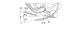
- FIG. 4B is a conceptual diagram illustrating an example of an opening angle between the wind direction adjusting blade 31 and the Coanda blade 32.
- the wind direction adjusting blade 31 and the Coanda blade 32 have an inner angle formed by the tangent of the end F of the scroll 17 and the Coanda blade 32 and the tangent of the end F of the scroll 17. It is preferable to take a posture that satisfies the condition that it is larger than the inner angle formed by the wind direction adjusting blade 31. 5A (the inner angle R2 formed by the tangent line L0 of the terminal end F of the scroll 17 and the Coanda blade 32 when the Coanda airflow is blown forward and the tangent line L0 of the terminal end F of the scroll 17 and the airflow direction adjusting blade 31 are formed.
- Comparison diagram with inner angle R1) and FIG. 5B inner angle R2 formed between tangent L0 of end F of scroll 17 and Coanda blade 32 when Coanda airflow ceiling is blown, tangent L0 of end F of scroll 17 and wind direction adjusting blade 31) (Refer to the comparison figure with the internal angle R1).
- 3C is a side view of the wind direction adjusting blade 31 and the Coanda blade 32 during the Coanda airflow forward blow.
- the control unit 40 moves the airflow direction adjustment blade 31 until the tangent L1 at the front end E1 of the inner side surface 31b of the airflow direction adjustment blade 31 becomes lower than the horizontal. Rotate.
- the control unit 40 rotates the Coanda blade 32 until the outer surface 32a of the Coanda blade 32 becomes substantially horizontal.
- the Coanda blade 32 is rotated until the tangent L2 at the front end E2 of the outer surface 32a becomes substantially horizontal. That is, as shown in FIG. 5A, the inner angle R2 formed by the tangent line L0 and the tangent line L2 is larger than the inner angle R1 formed by the tangent line L0 and the tangent line L1.
- the conditioned air adjusted by the wind direction adjusting blade 31 to the front lower blowing becomes a flow attached to the outer surface 32a of the Coanda blade 32 by the Coanda effect, and changes to a Coanda airflow along the outer surface 32a. Therefore, even if the tangent L1 direction at the front end E1 of the airflow direction adjusting blade 31 is the front lower blowing, the tangential L2 direction at the front end E2 of the Coanda blade 32 is horizontal, so that the conditioned air is generated by the Coanda effect by the Coanda effect. It blows off in the tangent L2 direction at the front end E2 of the outer side surface 32a, that is, in the horizontal direction.
- 3D is a side view of the wind direction adjusting blade 31 and the Coanda blade 32 when the Coanda airflow ceiling is blown.
- the control unit 40 rotates the airflow direction adjusting blade 31 until the tangent L1 at the front end E1 of the inner side surface 31b of the airflow direction adjusting blade 31 becomes horizontal.
- the control part 40 rotates the Coanda blade
- the conditioned air adjusted to be blown horizontally by the airflow direction adjusting blade 31 becomes a flow adhered to the outer surface 32a of the Coanda blade 32 by the Coanda effect, and changes to a Coanda airflow along the outer surface 32a.
- the tangential L2 direction at the front end E2 of the Coanda blade 32 is forward upward blowing, so that the conditioned air is generated by the Coanda effect by the Coanda effect. It blows out in the tangent L2 direction at the front end E2 of the outer side surface 32a, that is, the ceiling direction. Since the front end portion of the Coanda blade 32 protrudes outward from the air outlet 15, the Coanda airflow reaches further away. Furthermore, since the tip of the Coanda blade 32 is located above the air outlet 15, the generation of an airflow that passes above the Coanda blade 32 is suppressed, and the upward induction of the Coanda airflow is hardly inhibited. .
- the Coanda blades 32 are separated from the front surface of the indoor unit and the inclination becomes gentle, and the conditioned air becomes more susceptible to the Coanda effect in front of the front panel 11b.
- the size in the longitudinal direction of the Coanda blade 32 is not less than the size in the longitudinal direction of the wind direction adjusting blade 31. Therefore, all of the conditioned air whose wind direction is adjusted by the wind direction adjusting blade 31 can be received by the Coanda blade 32, and the effect of preventing the conditioned air from being short-circuited from the side of the Coanda blade 32 is also achieved.
- FIG. 6B is a side view of the air-conditioning indoor unit installation space showing the wind direction of the conditioned air when the wind direction adjusting blade 31 faces downward.
- FIG. 6C is a side view of the air conditioning indoor unit installation space showing the wind direction of the Coanda airflow when the Coanda blade 32 is in the ceiling blowing posture.
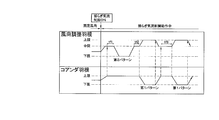
- FIG. 7 is a flowchart showing the operation of the wind direction adjusting blade 31 and the Coanda blade 32 during the fluctuation airflow A control.
- the wind direction adjusting blade 31 swings between an upper limit position and a lower limit position with an operation of waiting at an intermediate position interposed therebetween.
- the control unit 40 irregularly changes the time during which the wind direction adjusting blade 31 waits at the intermediate position (hereinafter referred to as the intermediate position standby time), and thereby the wind moving away from the wind approaching the resident. Since the combination of the two is irregularly changed, it is possible to provide residents with various winds.
- the Coanda blade 32 swings between the upper limit position and the lower limit position. As shown in FIG.
- the airflow direction adjustment blade 31 swings between the upper limit position and the intermediate position.
- One pattern and a second pattern in which the wind direction adjusting blade 31 swings between the intermediate position and the lower limit position while the Coanda blade 32 stands by at the upper limit position are included.
- the operation in which the Coanda blade 32 moves from the upper limit position to the lower limit position is synchronized with the timing at which the wind direction adjustment blade 31 moves from the intermediate position to the upper limit position.
- the operation of the Coanda blade 32 moving from the lower limit position to the upper limit position is synchronized with the timing when the wind direction adjusting blade 31 is moved from the upper limit position to the intermediate position.
- the Coanda blade 32 is controlled so as to be in the upper limit position, so that no Coanda airflow is generated.
- the intermediate position standby time of the wind direction adjusting blade 31 is irregularly changed, the time during which the Coanda airflow is not generated is irregularly changed, and the intervals at which the wind is unexpectedly changed are irregularly changed by the residents.
- a variety of winds can be provided.
- the wind direction adjusting blade 31 is in the intermediate position and the Coanda blade 32 is in the upper limit position. Time is measured as standby time.
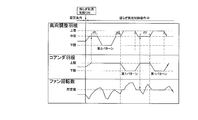
- FIG. 8 is a flowchart showing the operation of the wind direction adjusting blade 31 and the Coanda blade 32 and the fan rotation speed of the indoor fan 14 during the fluctuation airflow B control.
- the operation of the wind direction adjusting blade 31 and the Coanda blade 32 is the same as that during the fluctuation airflow A control, but the fan rotational speed of the indoor fan 14 is changed according to the operation of the wind direction adjusting blade 31 and the Coanda blade 32. Is different from the fluctuation airflow A control.
- the fan rotation speed of the indoor fan 14 is increased to a predetermined value.
- the predetermined value refers to the number of rotations of the fan for ensuring the minimum air volume that allows the wind separated from the Coanda blades 32 to reach the occupant. Therefore, when the fan rotation speed of the indoor fan 14 rises to a predetermined value at the time when the Coanda blade 32 starts moving from the upper limit position to the lower limit position, the airflow is peeled off from the Coanda blade 32 and directed toward the resident. Unexpected wind is realized because the airflow surely reaches the residents.
- the wind direction adjusting blade 31 starts moving to the lower limit position after the first standby time tf1 has elapsed, and after reaching the lower limit position, it stops at the lower limit position for a predetermined time and starts moving again to the intermediate position.
- the wind direction adjusting blade 31 that has moved to the intermediate position then waits for the second waiting time tf2 and then starts to move to the upper limit position.
- the Coanda blade 32 starts to move to the lower limit position in synchronization.
- the Coanda blade 32 that has reached the lower limit position waits there for a predetermined time and then starts to rise toward the upper limit position.
- the wind direction adjusting blade 31 that has reached the upper limit position also stands by for a certain period of time, and starts moving toward the intermediate position synchronously when the Coanda blade 32 starts moving to the upper limit position.
- the wind direction adjusting blade 31 that has reached the intermediate position waits there. During this time, the Coanda blade 32 reaches the upper limit position.
- the control unit 40 measures the standby time starting from the time when the wind direction adjusting blade 31 reaches the intermediate position and the Coanda blade 32 reaches the upper limit position.
- the wind direction adjusting blade 31 starts moving to the upper limit position after waiting for the second waiting time tf3. At this time, the Coanda blade 32 starts to move to the lower limit position in synchronization.
- the Coanda blade 32 that has reached the lower limit position waits there for a predetermined time and then starts to rise toward the upper limit position.
- the wind direction adjusting blade 31 that has already reached the upper limit position is also waiting there for a certain period of time, but in synchronization with the Coanda blade 32 starting to move to the upper limit position, it moves toward the intermediate position. Start. Thereafter, it operates according to wind direction patterns with different standby times set in advance.
- control part 40 can also change each of the time for which the wind direction adjustment blade
- the fan rotation speed of the indoor fan 14 repeatedly rises and falls irregularly according to a preset fluctuation amount pattern. However, while the Coanda blade 32 is at the lower limit position, the fan rotation speed is irregularly changed within a predetermined value or more. Then, when the Coanda blade 32 starts to move from the lower limit position to the upper limit position and the Coanda blade 32 reaches the upper limit position, the restriction is released and the fan rotation speed is changed irregularly.
- the fan rotation speed of the indoor fan 14 in accordance with the operation of the wind direction adjusting blade 31 and the Coanda blade 32, low-frequency fluctuations and swells are realized, and conditioned air that is closer to natural wind is occupant. Can be provided.
- the fan speed is controlled to be a predetermined value or more.
- the control unit 40 controls the operation of the Coanda blade during fluctuation airflow control, and executes a mode including a Coanda generation state in which the Coanda airflow is generated and a Coanda non-generation state in which the Coanda airflow is not generated. Therefore, when the fluctuation airflow control is performed, the flow of the wind is diversified by suddenly generating the Coanda airflow, and the conditioned air closer to the natural wind can be provided to the occupant.
- control unit 40 changes the air volume of the conditioned air during fluctuation air flow control, the conditioned air becomes an air flow that is closer to the natural wind by changing the air volume in addition to the wind direction, providing a comfortable air-conditioned space for the residents. can do.
- the control unit 40 changes the air volume of the conditioned air to a predetermined value during the time period in which the Coanda airflow is generated, that is, the period during which the Coanda blade 32 moves from the upper limit position to the lower limit position, waits, and moves to the upper limit position again To do. Therefore, the conditioned air at the moment when the Coanda effect is eliminated can surely reach the occupant, thus realizing an “unexpected wind”.
- (6) Modified Example In the above embodiment, both the fluctuation airflow A control and the fluctuation airflow B control, the Coanda generation state in which the Coanda airflow is generated by irregularly swinging the wind direction adjusting blade 31 and the Coanda blade 32, and the Coanda. Although the mode including the Coanda non-generation state that does not generate the airflow is realized, it is not limited to this. Below, the modification of fluctuation airflow control is demonstrated.
- FIG. 9 is a flowchart showing the operation of the wind direction adjusting blade 31 and the Coanda blade 32 during fluctuation airflow control in the first modification.
- the fluctuation airflow control in the first modification is performed by oscillating only the airflow direction adjusting blade 31 and the time zone in which the A mode in which the airflow direction adjusting blade 31 and the Coanda blade 32 are swung to generate the fluctuating airflow is executed. It is characterized by mixing the time zone in which the B mode for generating the fluctuation airflow is executed.
- the Coanda blade 32 swings between the upper limit position and the lower limit position.
- the controller 40 irregularly changes the time during which the Coanda blade 32 waits at the upper limit position, and accordingly, the time during which the Coanda airflow is not generated irregularly changes, and the wind blows unexpectedly to the resident. Since the intervals are changed irregularly, various winds can be provided by residents.
- the Coanda blade 32 is moved to the fully closed position, the Coanda airflow is not always generated regardless of the upper and lower limit positions of the wind direction adjusting blade 31.
- the wind direction adjusting blade 31 swings between the upper limit position and the lower limit position with the operation of waiting at the intermediate position interposed therebetween.
- the control unit 40 irregularly changes the time during which the wind direction adjusting blade 31 waits at the intermediate position, and thereby, the combination of the wind approaching the resident and the wind moving away is irregularly switched. So it can provide residents with a variety of winds.
- FIG. 10 is a flowchart showing the operation of the wind direction adjusting blade 31 and the Coanda blade 32 during fluctuation airflow control in the second modification.
- the fluctuation airflow control in the second modification includes a C mode in which only the Coanda blade 32 is swung to generate a fluctuation airflow in addition to the A mode and the B mode of the fluctuation airflow control in the first modification. It is characteristic that it is made to do.
- the Coanda blade 32 is instantaneously adsorbed on the lower surface of the Coanda blade 32 and becomes a Coanda airflow. A state where it is not suitable for the resident and a state where the Coanda effect is canceled and the resident is again directed are repeated. That is, a certain “unexpected wind” can be generated.
- conditioned air close to natural wind can be provided to the occupant, so that it is useful not only for wall-mounted air conditioning indoor units but also for air purifiers.
Landscapes
- Engineering & Computer Science (AREA)
- Chemical & Material Sciences (AREA)
- Combustion & Propulsion (AREA)
- Mechanical Engineering (AREA)
- General Engineering & Computer Science (AREA)
- Air Conditioning Control Device (AREA)
- Air-Flow Control Members (AREA)
Abstract
風の流れの多様化によって、より自然風に近い調和空気を実現することができる空調室内機を提供する。空調室内機(10)では、制御部(40)は、揺らぎ気流制御時に、コアンダ羽根の動作を制御して、コアンダ気流を発生させるコアンダ発生状態と、コアンダ気流を発生させないコアンダ非発生状態とを含むモードを実行するので、揺らぎ気流制御時に、突然にコアンダ気流が発生することによって風の流れが多様化し、より自然風に近い調和空気を居住者に提供することができる。
Description
本発明は、空調室内機に関し、特にコアンダ効果を利用する空調室内機に関する。
近年、居住空間の快適性を向上させる目的で、空調室内機から吹き出される調和空気を自然気流に近づける取り組みが行われている。例えば、特許文献1(特開2001-41538号公報)に記載されている空気調和機では、調和空気の風向を上下に揺動する3枚の羽根で調節し、その際、3枚の羽根の位相を異ならせることによって自然風に近い気流を実現しようとするものである。
しかしながら、上記のような構成では、気流は人に対して徐々に近づき徐々に遠ざかるような当たり方をするだけで、多様な風の流れを実現することはできない。
本発明の課題は、風の流れの多様化によって、より自然風に近い調和空気を実現することができる空調室内機を提供することにある。
本発明の課題は、風の流れの多様化によって、より自然風に近い調和空気を実現することができる空調室内機を提供することにある。
本発明の第1観点に係る空調室内機は、吹出口から吹き出される調和空気の風向を上下に変化させて揺らぎ気流を発生させる空調室内機であって、コアンダ羽根と、制御部とを備えている。コアンダ羽根は、吹出口の近傍に設けられ、コアンダ効果により調和空気を自己の下面に沿わせたコアンダ気流にして所定の方向へ誘導する。制御部は、調和空気の揺らぎ気流を制御する。また、制御部は、揺らぎ気流制御時に、コアンダ羽根の動作を制御して、コアンダ気流を発生させるコアンダ発生状態と、コアンダ気流を発生させないコアンダ非発生状態とを含む第1モードを実行する。
コアンダ羽根は、コアンダ効果によって調和空気の流れを瞬間的に所定方向に向うコアンダ気流に変える。言い換えると、コアンダ効果が解消されるとコアンダ気流は瞬間的に元の流れに切り換わる。調和空気が居住者に当たっているような場合、コアンダ気流が発生したと同時に居住者に調和空気が当たらなくなり、コアンダ効果が解消されたと同時に調和空気が居住者に当たる。この空調室内機では、揺らぎ気流制御時に、突然にコアンダ気流が発生することによって風の流れが多様化するので、より自然風に近い調和空気を居住者に提供することができる。
コアンダ羽根は、コアンダ効果によって調和空気の流れを瞬間的に所定方向に向うコアンダ気流に変える。言い換えると、コアンダ効果が解消されるとコアンダ気流は瞬間的に元の流れに切り換わる。調和空気が居住者に当たっているような場合、コアンダ気流が発生したと同時に居住者に調和空気が当たらなくなり、コアンダ効果が解消されたと同時に調和空気が居住者に当たる。この空調室内機では、揺らぎ気流制御時に、突然にコアンダ気流が発生することによって風の流れが多様化するので、より自然風に近い調和空気を居住者に提供することができる。
本発明の第2観点に係る空調室内機は、吹出口から吹き出される調和空気の風向を上下に変化させて揺らぎ気流を発生させる空調室内機であって、コアンダ羽根と、制御部とを備えている。コアンダ羽根は、吹出口の近傍に設けられ、コアンダ効果により調和空気を自己の下面に沿わせたコアンダ気流にして所定の方向へ誘導する。制御部は、調和空気の風向変化パターンを変更して揺らぎ気流を制御する。また、制御部には、少なくとも、第1モードと第2モードとが実行可能なモードとして予め設定されている。第1モードは、揺らぎ気流制御時に、コアンダ羽根の動作を制御して、コアンダ気流を発生させるコアンダ発生状態と、コアンダ気流を発生させないコアンダ非発生状態とを含むモードである。第2モードは、揺らぎ気流制御時に、コアンダ気流を常時発生させないモードである。さらに、制御部は、揺らぎ気流制御時に、第1モードを実行する時間帯と、第2モードを実行する時間帯とを混在させる。
コアンダ羽根は、コアンダ効果によって調和空気の流れを瞬間的に所定方向に向うコアンダ気流に変える。言い換えると、コアンダ効果が解消されるとコアンダ気流は瞬間的に元の流れに切り換わる。調和空気が居住者に当たっているような場合、コアンダ気流が発生したと同時に居住者に調和空気が当たらなくなり、コアンダ効果が解消されたと同時に調和空気が居住者に当たる。この空調室内機では、揺らぎ気流制御時に、第1モードを実行する時間帯と第2モードを実行する時間帯とが混在することによって風の流れが多様化するので、より自然風に近い調和空気を居住者に提供することができる。
本発明の第3観点に係る空調室内機は、第1観点または第2観点に係る空調室内機であって、水平面に対する調和空気の吹出角度を変更する風向調整羽根をさらに備えている。また、制御部は、風向調整羽根およびコアンダ羽根のいずれか一方または両方を用いて揺らぎ気流を制御する。
この空調室内機では、風向調整羽根だけによる揺らぎ気流と、コアンダ羽根だけによる揺らぎ気流と、風向調整羽根およびコアンダ羽根による揺らぎ気流とを含む3種類の揺らぎ気流を実現することができ、居住者に対して変化に富んだ揺らぎ気流を提供することができる。
本発明の第4観点に係る空調室内機は、第3観点に係る空調室内機であって、揺らぎ気流制御が、AモードとBモードとを含んでいる。Aモードは、風向調整羽根およびコアンダ羽根を揺動させて揺らぎ気流を発生させる。Bモードは、風向調整羽根だけを揺動させて揺らぎ気流を発生させる。
この空調室内機では、Aモードにおいて、居住者に徐々に近づき徐々に遠ざかる揺らぎ気流が、コアンダ羽根の揺動によってコアンダ羽根の下面に瞬間的に吸着されコアンダ気流となり居住者に向わなくなる状態と、コアンダ効果か解消され再び居住者に向う状態とが繰り返される。また、Bモードにおいて、調和空気が、風向調整羽根によって上下に揺動し、居住者に徐々に近づき徐々に遠ざかる揺らぎ気流となる。つまり、AモードとBモードとを混在させることによって、「不意の風」をともなう揺らぎ気流と、「不意の風」をともなわない揺らぎ気流とを実現することができる。
この空調室内機では、Aモードにおいて、居住者に徐々に近づき徐々に遠ざかる揺らぎ気流が、コアンダ羽根の揺動によってコアンダ羽根の下面に瞬間的に吸着されコアンダ気流となり居住者に向わなくなる状態と、コアンダ効果か解消され再び居住者に向う状態とが繰り返される。また、Bモードにおいて、調和空気が、風向調整羽根によって上下に揺動し、居住者に徐々に近づき徐々に遠ざかる揺らぎ気流となる。つまり、AモードとBモードとを混在させることによって、「不意の風」をともなう揺らぎ気流と、「不意の風」をともなわない揺らぎ気流とを実現することができる。
本発明の第5観点に係る空調室内機は、第4観点に係る空調室内機であって、揺らぎ気流制御は、コアンダ羽根だけを揺動させて揺らぎ気流を発生させるCモードをさらに含んでいる。
この空調室内機では、Cモードにおいて、調和空気の方向が一定であるときにコアンダ羽根の揺動によってコアンダ羽根の下面に瞬間的に吸着されコアンダ気流となり居住者に向わなくなる状態と、コアンダ効果が解消され再び居住者に向う状態とが繰り返される。つまり、一定の「不意の風」を発生させることができる。
この空調室内機では、Cモードにおいて、調和空気の方向が一定であるときにコアンダ羽根の揺動によってコアンダ羽根の下面に瞬間的に吸着されコアンダ気流となり居住者に向わなくなる状態と、コアンダ効果が解消され再び居住者に向う状態とが繰り返される。つまり、一定の「不意の風」を発生させることができる。
本発明の第6観点に係る空調室内機は、第1観点または第2観点に係る空調室内機であって、制御部が、揺らぎ気流制御時に調和空気の風量を変化させる。
この空調室内機では、風向に加えて風量が変化することによって、調和空気がさらに自然風に近い気流となるので、居住者により心地よい空調空間を提供することができる。
この空調室内機では、風向に加えて風量が変化することによって、調和空気がさらに自然風に近い気流となるので、居住者により心地よい空調空間を提供することができる。
本発明の第7観点に係る空調室内機は、第6観点に係る空調室内機であって、制御部が、少なくともコアンダ気流を発生させる時間帯に調和空気の風量を所定風量へ変更する。
この空調室内機では、「不意の風」は居住者に届かなければ効果がない。つまり、コアンダ気流を発生させる時間帯の風量が低下していると、コアンダ効果を解消した瞬間の調和空気は風量低下によって居住者に届かず「不意の風」にならない。
この空調室内機では、少なくともコアンダ気流を発生させる時間帯は調和空気の風量を所定風量へ変更しており、コアンダ効果が解消された瞬間の調和空気は所定風量を維持するので、「不意の風」を実現できる。
この空調室内機では、「不意の風」は居住者に届かなければ効果がない。つまり、コアンダ気流を発生させる時間帯の風量が低下していると、コアンダ効果を解消した瞬間の調和空気は風量低下によって居住者に届かず「不意の風」にならない。
この空調室内機では、少なくともコアンダ気流を発生させる時間帯は調和空気の風量を所定風量へ変更しており、コアンダ効果が解消された瞬間の調和空気は所定風量を維持するので、「不意の風」を実現できる。
本発明の第1観点に係る空調室内機では、揺らぎ気流制御時に、突然にコアンダ気流が発生することによって、風の流れが多様化するので、より自然風に近い調和空気を居住者に提供することができる。
本発明の第2観点に係る空調室内機では、揺らぎ気流制御時に、第1モードを実行する時間帯と第2モードを実行する時間帯とが混在することによって風の流れが多様化するので、より自然風に近い調和空気を居住者に提供することができる。
本発明の第3観点に係る空調室内機では、風向調整羽根だけによる揺らぎ気流と、コアンダ羽根だけによる揺らぎ気流と、風向調整羽根およびコアンダ羽根による揺らぎ気流とを含む3種類の揺らぎ気流を実現することができ、居住者に対して変化に富んだ揺らぎ気流を提供することができる。
本発明の第2観点に係る空調室内機では、揺らぎ気流制御時に、第1モードを実行する時間帯と第2モードを実行する時間帯とが混在することによって風の流れが多様化するので、より自然風に近い調和空気を居住者に提供することができる。
本発明の第3観点に係る空調室内機では、風向調整羽根だけによる揺らぎ気流と、コアンダ羽根だけによる揺らぎ気流と、風向調整羽根およびコアンダ羽根による揺らぎ気流とを含む3種類の揺らぎ気流を実現することができ、居住者に対して変化に富んだ揺らぎ気流を提供することができる。
本発明の第4観点に係る空調室内機では、AモードとBモードとを混在させることによって、「不意の風」をともなう揺らぎ気流と、「不意の風」をともなわない揺らぎ気流とを実現することができる。
本発明の第5観点に係る空調室内機では、Cモードにおいて、調和空気の方向が一定であるときにコアンダ羽根の揺動によってコアンダ羽根の下面に瞬間的に吸着されコアンダ気流となり居住者に向わなくなる状態と、コアンダ効果が解消され再び居住者に向う状態とが繰り返される。つまり、一定の「不意の風」を発生させることができる。
本発明の第6観点に係る空調室内機では、風向に加えて風量が変化することによって、調和空気がさらに自然風に近い気流となるので、居住者により心地よい空調空間を提供することができる。
本発明の第5観点に係る空調室内機では、Cモードにおいて、調和空気の方向が一定であるときにコアンダ羽根の揺動によってコアンダ羽根の下面に瞬間的に吸着されコアンダ気流となり居住者に向わなくなる状態と、コアンダ効果が解消され再び居住者に向う状態とが繰り返される。つまり、一定の「不意の風」を発生させることができる。
本発明の第6観点に係る空調室内機では、風向に加えて風量が変化することによって、調和空気がさらに自然風に近い気流となるので、居住者により心地よい空調空間を提供することができる。
本発明の第7観点に係る空調室内機では、少なくともコアンダ気流を発生させる時間帯は調和空気の風量を所定風量へ変更しており、コアンダ効果が解消された瞬間の調和空気は所定風量を維持するので、「不意の風」を実現できる。
以下、図面を参照しながら、本発明の実施形態について説明する。なお、以下の実施形態は、本発明の具体例であって、本発明の技術的範囲を限定するものではない。
(1)空調室内機10の構成
図1は、本発明の一実施形態に係る運転停止時の空調室内機10の断面図である。また、図2は、運転時の空調室内機10の断面図である。図1及び図2において、空調室内機10は壁掛けタイプであり、本体ケーシング11、室内熱交換器13、室内ファン14、底フレーム16、及び制御部40が搭載されている。
本体ケーシング11は、天面部11a、前面パネル11b、背面板11c及び下部水平板11dを有し、内部に室内熱交換器13、室内ファン14、底フレーム16、及び制御部40を収納している。
(1)空調室内機10の構成
図1は、本発明の一実施形態に係る運転停止時の空調室内機10の断面図である。また、図2は、運転時の空調室内機10の断面図である。図1及び図2において、空調室内機10は壁掛けタイプであり、本体ケーシング11、室内熱交換器13、室内ファン14、底フレーム16、及び制御部40が搭載されている。
本体ケーシング11は、天面部11a、前面パネル11b、背面板11c及び下部水平板11dを有し、内部に室内熱交換器13、室内ファン14、底フレーム16、及び制御部40を収納している。
天面部11aは、本体ケーシング11の上部に位置し、天面部11aの前部には、吸込口(図示せず)が設けられている。
前面パネル11bは室内機の前面部を構成しており、吸込口がないフラットな形状を成している。また、前面パネル11bは、その上端が天面部11aに回動自在に支持され、ヒンジ式に動作することができる。
室内熱交換器13及び室内ファン14は、底フレーム16に取り付けられている。室内熱交換器13は、通過する空気との間で熱交換を行う。また、室内熱交換器13は、側面視において両端が下方に向いて屈曲する逆V字状の形状を成し、その下方に室内ファン14が位置する。室内ファン14は、クロスフローファンであり、室内から取り込んだ空気を、室内熱交換器13に当てて通過させた後、室内に吹き出す。
前面パネル11bは室内機の前面部を構成しており、吸込口がないフラットな形状を成している。また、前面パネル11bは、その上端が天面部11aに回動自在に支持され、ヒンジ式に動作することができる。
室内熱交換器13及び室内ファン14は、底フレーム16に取り付けられている。室内熱交換器13は、通過する空気との間で熱交換を行う。また、室内熱交換器13は、側面視において両端が下方に向いて屈曲する逆V字状の形状を成し、その下方に室内ファン14が位置する。室内ファン14は、クロスフローファンであり、室内から取り込んだ空気を、室内熱交換器13に当てて通過させた後、室内に吹き出す。
本体ケーシング11の下部には、吹出口15が設けられている。吹出口15には、吹出口15から吹き出される調和空気の方向を変更する風向調整羽根31が回動自在に取り付けられている。風向調整羽根31は、モータ(図示せず)によって駆動し、調和空気の方向を変更するだけでなく、吹出口15を開閉することもできる。風向調整羽根31は、傾斜角が異なる複数の姿勢をとることが可能である。
また、吹出口15の近傍にはコアンダ羽根32が設けられている。コアンダ羽根32は、モータ(図示せず)によって前後方向に傾斜した姿勢をとることが可能であり、運転停止時に前面パネル11bに設けられた収容部130に収容される。コアンダ羽根32は、傾斜角が異なる複数の姿勢をとることが可能である。
また、吹出口15は、吹出流路18によって本体ケーシング11の内部と繋がっている。吹出流路18は、吹出口15から底フレーム16のスクロール17に沿って形成されている。
また、吹出口15の近傍にはコアンダ羽根32が設けられている。コアンダ羽根32は、モータ(図示せず)によって前後方向に傾斜した姿勢をとることが可能であり、運転停止時に前面パネル11bに設けられた収容部130に収容される。コアンダ羽根32は、傾斜角が異なる複数の姿勢をとることが可能である。
また、吹出口15は、吹出流路18によって本体ケーシング11の内部と繋がっている。吹出流路18は、吹出口15から底フレーム16のスクロール17に沿って形成されている。
室内空気は、室内ファン14の稼動によって吸込口、室内熱交換器13を経て室内ファン14に吸い込まれ、室内ファン14から吹出流路18を経て吹出口15から吹き出される。
制御部40は、本体ケーシング11を前面パネル11bから視て室内熱交換器13及び室内ファン14の右側方に位置しており、室内ファン14の回転数制御、風向調整羽根31及びコアンダ羽根32の動作制御を行う。
(2)詳細構成
(2-1)前面パネル11b
図1に示すように、前面パネル11bは本体ケーシング11の上部前方からなだらかな円弧曲面を描きながら下部水平板11dの前方エッジに向かって延びている。前面パネル11bの下部に本体ケーシング11の内側に向かって窪んだ領域がある。この領域の窪み深さはコアンダ羽根32の厚み寸法に合うように設定されており、コアンダ羽根32が収容される収容部130を成している。収容部130の表面もなだらかな円弧曲面である。
制御部40は、本体ケーシング11を前面パネル11bから視て室内熱交換器13及び室内ファン14の右側方に位置しており、室内ファン14の回転数制御、風向調整羽根31及びコアンダ羽根32の動作制御を行う。
(2)詳細構成
(2-1)前面パネル11b
図1に示すように、前面パネル11bは本体ケーシング11の上部前方からなだらかな円弧曲面を描きながら下部水平板11dの前方エッジに向かって延びている。前面パネル11bの下部に本体ケーシング11の内側に向かって窪んだ領域がある。この領域の窪み深さはコアンダ羽根32の厚み寸法に合うように設定されており、コアンダ羽根32が収容される収容部130を成している。収容部130の表面もなだらかな円弧曲面である。
(2-2)吹出口15
図1に示すように、吹出口15は、本体ケーシング11の下部に形成されており、横方向(図1紙面と直交する方向)を長辺とする長方形の開口である。吹出口15の下端は下部水平板11dの前方エッジに接しており、吹出口15の下端と上端とを結ぶ仮想面は前方上向きに傾斜している。
(2-3)スクロール17
スクロール17は、室内ファン14に対峙するように湾曲した隔壁であり、底フレーム16の一部である。スクロール17の終端Fは、吹出口15の周縁近傍まで到達している。吹出流路18を通る空気は、スクロール17に沿って進み、スクロール17の終端Fの接線方向に送られる。したがって、吹出口15に風向調整羽根31がなければ、吹出口15から吹き出される調和空気の風向は、スクロール17の終端Fの接線L0に概ね沿った方向である。
図1に示すように、吹出口15は、本体ケーシング11の下部に形成されており、横方向(図1紙面と直交する方向)を長辺とする長方形の開口である。吹出口15の下端は下部水平板11dの前方エッジに接しており、吹出口15の下端と上端とを結ぶ仮想面は前方上向きに傾斜している。
(2-3)スクロール17
スクロール17は、室内ファン14に対峙するように湾曲した隔壁であり、底フレーム16の一部である。スクロール17の終端Fは、吹出口15の周縁近傍まで到達している。吹出流路18を通る空気は、スクロール17に沿って進み、スクロール17の終端Fの接線方向に送られる。したがって、吹出口15に風向調整羽根31がなければ、吹出口15から吹き出される調和空気の風向は、スクロール17の終端Fの接線L0に概ね沿った方向である。
(2-4)垂直風向調整板20
垂直風向調整板20は、図1及び図2に示すように、複数の羽根片201と、複数の羽根片201を連結する連結棒203を有している。また、垂直風向調整板20は、吹出流路18において、風向調整羽根31よりも室内ファン14近傍に配置されている。
複数枚の羽根片201は、連結棒203が吹出口15の長手方向に沿って水平往復移動することによって、その長手方向に対して垂直な状態を中心に左右に揺動する。なお、連結棒203は、モータ(図示せず)によって水平往復移動する。
(2-5)風向調整羽根31
風向調整羽根31は、吹出口15を塞ぐことができる程度の面積を有している。風向調整羽根31が吹出口15を閉じた状態において、その外側面31aは前面パネル11bの曲面の延長上にあるような外側に凸のなだらかな円弧曲面に仕上げられている。また、風向調整羽根31の内側面31b(図2参照)も、外面にほぼ平行な円弧曲面を成している。
垂直風向調整板20は、図1及び図2に示すように、複数の羽根片201と、複数の羽根片201を連結する連結棒203を有している。また、垂直風向調整板20は、吹出流路18において、風向調整羽根31よりも室内ファン14近傍に配置されている。
複数枚の羽根片201は、連結棒203が吹出口15の長手方向に沿って水平往復移動することによって、その長手方向に対して垂直な状態を中心に左右に揺動する。なお、連結棒203は、モータ(図示せず)によって水平往復移動する。
(2-5)風向調整羽根31
風向調整羽根31は、吹出口15を塞ぐことができる程度の面積を有している。風向調整羽根31が吹出口15を閉じた状態において、その外側面31aは前面パネル11bの曲面の延長上にあるような外側に凸のなだらかな円弧曲面に仕上げられている。また、風向調整羽根31の内側面31b(図2参照)も、外面にほぼ平行な円弧曲面を成している。
風向調整羽根31は、下端部に回動軸311を有している。回動軸311は、吹出口15の下端近傍で、本体ケーシング11に固定されているステッピングモータ(図示せず)の回転軸に連結されている。
回動軸311が図1正面視反時計方向に回動することによって、風向調整羽根31の上端が吹出口15の上端側から遠ざかるように動作して吹出口15を開ける。逆に、回動軸311が図1正面視時計方向に回動することによって、風向調整羽根31の上端が吹出口15の上端側へ近づくように動作して吹出口15を閉じる。
風向調整羽根31が吹出口15を開けている状態において、吹出口15から吹き出された調和空気は、風向調整羽根31の内側面31bに概ね沿って流れる。すなわち、スクロール17の終端Fの接線方向に概ね沿って吹き出された調和空気は、その風向が風向調整羽根31によってやや上向きに変更される。
回動軸311が図1正面視反時計方向に回動することによって、風向調整羽根31の上端が吹出口15の上端側から遠ざかるように動作して吹出口15を開ける。逆に、回動軸311が図1正面視時計方向に回動することによって、風向調整羽根31の上端が吹出口15の上端側へ近づくように動作して吹出口15を閉じる。
風向調整羽根31が吹出口15を開けている状態において、吹出口15から吹き出された調和空気は、風向調整羽根31の内側面31bに概ね沿って流れる。すなわち、スクロール17の終端Fの接線方向に概ね沿って吹き出された調和空気は、その風向が風向調整羽根31によってやや上向きに変更される。
(2-6)コアンダ羽根32
コアンダ羽根32は、空調運転が停止している間や後述する通常吹出モードでの運転では収容部130に収納されている。コアンダ羽根32は回動することによって収容部130から離れる。コアンダ羽根32の回動軸321は、収容部130の下端近傍で且つ本体ケーシング11の内側の位置(吹出流路18上壁の上方の位置)に設けられており、コアンダ羽根32の下端部と回動軸321とは所定の間隔を保って連結されている。それゆえ、回動軸321が回動してコアンダ羽根32が室内機前面部の収容部130から離れるほど、コアンダ羽根32の下端の高さ位置は低くなるように回転する。また、コアンダ羽根32が回転して開いたときの傾斜は室内機前面部の傾斜よりも緩やかである。
本実施形態では、収容部130は、送風路の外に設けられており、収容時にコアンダ羽根32の全体が送風路の外側に収容される。かかる構造に代えて、コアンダ羽根32の一部のみが送風路の外側に収容され、残りが送風路内(たとえば、送風経路の上壁部)に収容されるようにしてもよい。
コアンダ羽根32は、空調運転が停止している間や後述する通常吹出モードでの運転では収容部130に収納されている。コアンダ羽根32は回動することによって収容部130から離れる。コアンダ羽根32の回動軸321は、収容部130の下端近傍で且つ本体ケーシング11の内側の位置(吹出流路18上壁の上方の位置)に設けられており、コアンダ羽根32の下端部と回動軸321とは所定の間隔を保って連結されている。それゆえ、回動軸321が回動してコアンダ羽根32が室内機前面部の収容部130から離れるほど、コアンダ羽根32の下端の高さ位置は低くなるように回転する。また、コアンダ羽根32が回転して開いたときの傾斜は室内機前面部の傾斜よりも緩やかである。
本実施形態では、収容部130は、送風路の外に設けられており、収容時にコアンダ羽根32の全体が送風路の外側に収容される。かかる構造に代えて、コアンダ羽根32の一部のみが送風路の外側に収容され、残りが送風路内(たとえば、送風経路の上壁部)に収容されるようにしてもよい。
また、回動軸321が図1正面視反時計方向に回動することによって、コアンダ羽根32の上端および下端ともに円弧を描きながら収容部130から離れるが、そのとき、上端と吹出口より上方の室内機前面部の収容部130との最短距離は、下端と収容部130との最短距離より大きい。すなわち、コアンダ羽根32は前方に行くにしたがって前記室内機前面部から離れるような姿勢に制御される。そして、回動軸321が図1正面視時計方向に回動することによって、コアンダ羽根32は収容部130に近づき、最終的に収容部130に収容される。コアンダ羽根32の運転状態の姿勢としては、収容部130に収納された状態、回転して前方上向きに傾斜した姿勢、さらに回転してほぼ水平な姿勢、さらに回転して前方下向きに傾斜した姿勢がある。
コアンダ羽根32が収容部130に収容された状態で、コアンダ羽根32の外側面32aは前面パネル11bのなだらかな円弧曲面の延長上にあるような外側に凸のなだらかな円弧曲面に仕上げられている。また、コアンダ羽根32の内側面32bは、収容部130の表面に沿うような円弧曲面に仕上げられている。
コアンダ羽根32が収容部130に収容された状態で、コアンダ羽根32の外側面32aは前面パネル11bのなだらかな円弧曲面の延長上にあるような外側に凸のなだらかな円弧曲面に仕上げられている。また、コアンダ羽根32の内側面32bは、収容部130の表面に沿うような円弧曲面に仕上げられている。
また、コアンダ羽根32の長手方向の寸法は、風向調整羽根31の長手方向の寸法以上となるように設定されている。この理由は風向調整羽根31で風向調節された調和空気すべてをコアンダ羽根32で受けるためであり、その目的はコアンダ羽根32の側方からの調和空気がショートサーキットすることを防止することである。
(3)調和空気の方向制御
本実施形態の空調室内機は、調和空気の方向を制御する手段として、風向調整羽根31のみを回動させて調和空気の方向を調整する通常吹出モードと、風向調整羽根31及びコアンダ羽根32を回動させてコアンダ効果によって調和空気をコアンダ羽根32の外側面32aに沿わせたコアンダ気流にするコアンダ効果利用モードとを有している。
風向調整羽根31及びコアンダ羽根32は、上記各モードにおいて空気の吹出方向ごとに姿勢が変化するので、各姿勢について図面を参照しながら説明する。なお、吹出方向の選択は、ユーザーがリモコン等を介して行なうことができるものとする。また、モードの変更や吹出方向は自動的に変更されるように制御することも可能である。
(3)調和空気の方向制御
本実施形態の空調室内機は、調和空気の方向を制御する手段として、風向調整羽根31のみを回動させて調和空気の方向を調整する通常吹出モードと、風向調整羽根31及びコアンダ羽根32を回動させてコアンダ効果によって調和空気をコアンダ羽根32の外側面32aに沿わせたコアンダ気流にするコアンダ効果利用モードとを有している。
風向調整羽根31及びコアンダ羽根32は、上記各モードにおいて空気の吹出方向ごとに姿勢が変化するので、各姿勢について図面を参照しながら説明する。なお、吹出方向の選択は、ユーザーがリモコン等を介して行なうことができるものとする。また、モードの変更や吹出方向は自動的に変更されるように制御することも可能である。
(3-1)通常吹出モード
通常吹出モードは、風向調整羽根31のみを回動させて調和空気の方向を調整するモードであり、「通常前吹き」と「通常前方下吹き」とを含む。
(3-1-1)通常前吹き
図3Aは、調和空気が通常前吹き時の風向調整羽根31及びコアンダ羽根32の側面図である。図3Aにおいて、ユーザーが「通常前吹き」を選択したとき、制御部40は風向調整羽根31の内側面31bが略水平になる位置まで風向調整羽根31を回動させる。なお、本願実施形態のように風向調整羽根31の内側面31bが円弧曲面をなしている場合は、内側面31bの前方端E1における接線が略水平になるまで風向調整羽根31を回動させる。その結果、調和空気は、前吹き状態となる。
通常吹出モードは、風向調整羽根31のみを回動させて調和空気の方向を調整するモードであり、「通常前吹き」と「通常前方下吹き」とを含む。
(3-1-1)通常前吹き
図3Aは、調和空気が通常前吹き時の風向調整羽根31及びコアンダ羽根32の側面図である。図3Aにおいて、ユーザーが「通常前吹き」を選択したとき、制御部40は風向調整羽根31の内側面31bが略水平になる位置まで風向調整羽根31を回動させる。なお、本願実施形態のように風向調整羽根31の内側面31bが円弧曲面をなしている場合は、内側面31bの前方端E1における接線が略水平になるまで風向調整羽根31を回動させる。その結果、調和空気は、前吹き状態となる。
(3-1-2)通常前方下吹き
図3Bは、調和空気が通常前方下吹き時の風向調整羽根31及びコアンダ羽根32の側面図である。図3Bにおいて、ユーザーは吹出方向を「通常前吹き」よりも下方に向けたいとき、「通常前方下吹き」を選択すればよい。
このとき、制御部40は、風向調整羽根31の内側面31bの前方端E1における接線が水平よりも前下がりになるまで風向調整羽根31を回動させる。その結果、調和空気は、前方下吹き状態となる。
(3-1-3)風向自動
図6Aは、風向調整羽根31の上下遥動による調和空気の風向を示す空調室内機設置空間の側面図である。図6Aに示すような風向調整は、従来品にも実施されている、いわゆるオートルーバー機能による風向調整であって、人体400に風を当てる動作・当てない動作の繰り返し手段として利用される。
図3Bは、調和空気が通常前方下吹き時の風向調整羽根31及びコアンダ羽根32の側面図である。図3Bにおいて、ユーザーは吹出方向を「通常前吹き」よりも下方に向けたいとき、「通常前方下吹き」を選択すればよい。
このとき、制御部40は、風向調整羽根31の内側面31bの前方端E1における接線が水平よりも前下がりになるまで風向調整羽根31を回動させる。その結果、調和空気は、前方下吹き状態となる。
(3-1-3)風向自動
図6Aは、風向調整羽根31の上下遥動による調和空気の風向を示す空調室内機設置空間の側面図である。図6Aに示すような風向調整は、従来品にも実施されている、いわゆるオートルーバー機能による風向調整であって、人体400に風を当てる動作・当てない動作の繰り返し手段として利用される。
(3-2)コアンダ効果利用モード
コアンダ(効果)とは、気体や液体の流れのそばに壁があると、流れの方向と壁の方向とが異なっていても、壁面に沿った方向に流れようとする現象である(朝倉書店「法則の辞典」)。コアンダ利用モードは、このコアンダ効果を利用した「コアンダ気流前方吹き」および「コアンダ気流天井吹き」を含む。
また、調和空気の方向およびコアンダ気流の方向については、基準位置の取り方次第で定義の方法が異なるが、以下に一例を示す。図4Aは、調和空気の方向およびコアンダ気流の方向を示す概念図である。図4Aにおいて、コアンダ羽根32の外側面32a側にコアンダ効果を生じさせるには、風向調整羽根31によって変更された調和空気の方向(D1)の傾斜がコアンダ羽根32の姿勢(傾斜)に近くなる必要がある。両者が離れすぎているとコアンダ効果が生じない。そのため、本コアンダ効果利用モードでは、コアンダ羽根32と風向調整羽根31とが所定の開き角度以下になる必要があり、両羽根(31、32)がその範囲内を成すようにして、上記の関係が成立するようにしている。これにより、図4Aに示すように、調和空気の風向が風向調整羽根31によってD1に変更された後、さらにコアンダ効果によりD2に変更される。
コアンダ(効果)とは、気体や液体の流れのそばに壁があると、流れの方向と壁の方向とが異なっていても、壁面に沿った方向に流れようとする現象である(朝倉書店「法則の辞典」)。コアンダ利用モードは、このコアンダ効果を利用した「コアンダ気流前方吹き」および「コアンダ気流天井吹き」を含む。
また、調和空気の方向およびコアンダ気流の方向については、基準位置の取り方次第で定義の方法が異なるが、以下に一例を示す。図4Aは、調和空気の方向およびコアンダ気流の方向を示す概念図である。図4Aにおいて、コアンダ羽根32の外側面32a側にコアンダ効果を生じさせるには、風向調整羽根31によって変更された調和空気の方向(D1)の傾斜がコアンダ羽根32の姿勢(傾斜)に近くなる必要がある。両者が離れすぎているとコアンダ効果が生じない。そのため、本コアンダ効果利用モードでは、コアンダ羽根32と風向調整羽根31とが所定の開き角度以下になる必要があり、両羽根(31、32)がその範囲内を成すようにして、上記の関係が成立するようにしている。これにより、図4Aに示すように、調和空気の風向が風向調整羽根31によってD1に変更された後、さらにコアンダ効果によりD2に変更される。
また、本実施形態のコアンダ効果利用モードでは、コアンダ羽根32が風向調整羽根31の前方(吹出の下流側)かつ上方の位置あるのが好ましい。
また、風向調整羽根31とコアンダ羽根32との開き角度については、基準位置の取り方次第で定義の方法が異なるが、以下に一例を示す。図4Bは、風向調整羽根31とコアンダ羽根32との開き角度の一例を表す概念図である。図4Bにおいて、風向調整羽根31の内側面31bの前後端を結ぶ直線と水平線との角度を風向調整羽根31の傾斜角θ1とし、コアンダ羽根32の外側面32aの前後端を結ぶ直線と水平線との角度をコアンダ羽根32の傾斜角θ2としたとき、風向調整羽根31とコアンダ羽根32との開き角度θ=θ2-θ1である。なお、θ1及びθ2は絶対値ではなく、図4B正面視において水平線よりも下方となる場合は負の値である。
また、風向調整羽根31とコアンダ羽根32との開き角度については、基準位置の取り方次第で定義の方法が異なるが、以下に一例を示す。図4Bは、風向調整羽根31とコアンダ羽根32との開き角度の一例を表す概念図である。図4Bにおいて、風向調整羽根31の内側面31bの前後端を結ぶ直線と水平線との角度を風向調整羽根31の傾斜角θ1とし、コアンダ羽根32の外側面32aの前後端を結ぶ直線と水平線との角度をコアンダ羽根32の傾斜角θ2としたとき、風向調整羽根31とコアンダ羽根32との開き角度θ=θ2-θ1である。なお、θ1及びθ2は絶対値ではなく、図4B正面視において水平線よりも下方となる場合は負の値である。
「コアンダ気流前方吹き」および「コアンダ気流天井吹き」ともに、風向調整羽根31およびコアンダ羽根32は、スクロール17の終端Fの接線とコアンダ羽根32とが成す内角が、スクロール17の終端Fの接線と風向調整羽根31とが成す内角よりも大きい、という条件を満たす姿勢をとるのが好ましい。
なお、内角については、図5A(コアンダ気流前方吹き時のスクロール17の終端Fの接線L0とコアンダ羽根32とが成す内角R2と、スクロール17の終端Fの接線L0と風向調整羽根31とが成す内角R1との比較図)、および図5B(コアンダ気流天井吹き時のスクロール17の終端Fの接線L0とコアンダ羽根32とが成す内角R2と、スクロール17の終端Fの接線L0と風向調整羽根31とが成す内角R1との比較図)を参照のこと。
なお、内角については、図5A(コアンダ気流前方吹き時のスクロール17の終端Fの接線L0とコアンダ羽根32とが成す内角R2と、スクロール17の終端Fの接線L0と風向調整羽根31とが成す内角R1との比較図)、および図5B(コアンダ気流天井吹き時のスクロール17の終端Fの接線L0とコアンダ羽根32とが成す内角R2と、スクロール17の終端Fの接線L0と風向調整羽根31とが成す内角R1との比較図)を参照のこと。
また、図5A及び図5Bに示すように、コアンダ効果利用モードにおけるコアンダ羽根32では、コアンダ羽根32の先端部が水平より前方上向で、吹出口15よりも外側上方に位置する。その結果、コアンダ気流はより遠方に到達する上に、コアンダ羽根32の上側を通過するような強い気流の発生は抑制され、コアンダ気流の上方への誘導が阻害されにくくなる。
また、コアンダ羽根32の後端部の高さ位置は運転停止時よりも低くなっているので、上流側でのコアンダ効果によるコアンダ気流が生成し易い。
(3-2-1)コアンダ気流前方吹き
図3Cは、コアンダ気流前方吹き時の風向調整羽根31及びコアンダ羽根32の側面図である。図3Cにおいて、「コアンダ気流前方吹き」が選択されたとき、制御部40は、風向調整羽根31の内側面31bの前方端E1における接線L1が水平よりも前下がりになるまで風向調整羽根31を回動させる。
また、コアンダ羽根32の後端部の高さ位置は運転停止時よりも低くなっているので、上流側でのコアンダ効果によるコアンダ気流が生成し易い。
(3-2-1)コアンダ気流前方吹き
図3Cは、コアンダ気流前方吹き時の風向調整羽根31及びコアンダ羽根32の側面図である。図3Cにおいて、「コアンダ気流前方吹き」が選択されたとき、制御部40は、風向調整羽根31の内側面31bの前方端E1における接線L1が水平よりも前下がりになるまで風向調整羽根31を回動させる。
次に、制御部40は、コアンダ羽根32の外側面32aが略水平になる位置までコアンダ羽根32を回動させる。なお、本願実施形態のようにコアンダ羽根32の外側面32aが円弧曲面をなしている場合は、外側面32aの前方端E2における接線L2が略水平になるまでコアンダ羽根32を回動させる。つまり、図5Aに示すように、接線L0と接線L2とが成す内角R2は、接線L0と接線L1とが成す内角R1よりも大きくなる。
風向調整羽根31で前方下吹きに調整された調和空気は、コアンダ効果によってコアンダ羽根32の外側面32aに付着した流れとなり、この外側面32aに沿ったコアンダ気流に変わる。
したがって、風向調整羽根31の前方端E1における接線L1方向が前方下吹きであっても、コアンダ羽根32の前方端E2における接線L2方向が水平であるので、調和空気は、コアンダ効果によってコアンダ羽根32の外側面32aの前方端E2における接線L2方向、すなわち水平方向に吹き出される。
風向調整羽根31で前方下吹きに調整された調和空気は、コアンダ効果によってコアンダ羽根32の外側面32aに付着した流れとなり、この外側面32aに沿ったコアンダ気流に変わる。
したがって、風向調整羽根31の前方端E1における接線L1方向が前方下吹きであっても、コアンダ羽根32の前方端E2における接線L2方向が水平であるので、調和空気は、コアンダ効果によってコアンダ羽根32の外側面32aの前方端E2における接線L2方向、すなわち水平方向に吹き出される。
このように、コアンダ羽根32が室内機前面部から離れて傾斜が緩やかになり、調和空気が前面パネル11bよりも前方でコアンダ効果を受け易くなる。その結果、風向調整羽根31で風向調節された調和空気が前方下吹きであっても、コアンダ効果によって水平吹きの空気となる。これは、吹出口通過直後の空気を前面パネルに近づけて前面パネルのコアンダ効果で上向きにする方法に比べて、風向調整羽根31の通風抵抗による圧損が抑制されつつ風向が変更される。
(3-2-2)コアンダ気流天井吹き
図3Dは、コアンダ気流天井吹き時の風向調整羽根31及びコアンダ羽根32の側面図である。図3Dにおいて、「コアンダ気流天井吹き」が選択されたとき、制御部40は風向調整羽根31の内側面31bの前方端E1における接線L1が水平になるまで風向調整羽根31を回動させる。
(3-2-2)コアンダ気流天井吹き
図3Dは、コアンダ気流天井吹き時の風向調整羽根31及びコアンダ羽根32の側面図である。図3Dにおいて、「コアンダ気流天井吹き」が選択されたとき、制御部40は風向調整羽根31の内側面31bの前方端E1における接線L1が水平になるまで風向調整羽根31を回動させる。
次に、制御部40は、外側面32aの前方端E2における接線L2が前方上向きとなるまでコアンダ羽根32を回動させる。つまり、図5Bに示すように、接線L0と接線L2とが成す内角R2は、接線L0と接線L1とが成す内角R1よりも大きくなる。風向調整羽根31で水平吹きに調整された調和空気は、コアンダ効果によってコアンダ羽根32の外側面32aに付着した流れとなり、この外側面32aに沿ったコアンダ気流に変わる。
したがって、風向調整羽根31の前方端E1における接線L1方向が前方吹きであっても、コアンダ羽根32の前方端E2における接線L2方向が前方上吹きであるので、調和空気は、コアンダ効果によってコアンダ羽根32の外側面32aの前方端E2における接線L2方向、すなわち天井方向に吹き出される。コアンダ羽根32の先端部は吹出口15より外側に突出しているので、コアンダ気流はより遠方に到達する。さらに、コアンダ羽根32の先端部は吹出口15よりも上方に位置しているので、コアンダ羽根32の上側を通過するような気流の発生は抑制され、コアンダ気流の上方への誘導が阻害されにくい。
したがって、風向調整羽根31の前方端E1における接線L1方向が前方吹きであっても、コアンダ羽根32の前方端E2における接線L2方向が前方上吹きであるので、調和空気は、コアンダ効果によってコアンダ羽根32の外側面32aの前方端E2における接線L2方向、すなわち天井方向に吹き出される。コアンダ羽根32の先端部は吹出口15より外側に突出しているので、コアンダ気流はより遠方に到達する。さらに、コアンダ羽根32の先端部は吹出口15よりも上方に位置しているので、コアンダ羽根32の上側を通過するような気流の発生は抑制され、コアンダ気流の上方への誘導が阻害されにくい。
このように、コアンダ羽根32が室内機前面部から離れて傾斜が緩やかになり、調和空気が前面パネル11bよりも前方でコアンダ効果を受け易くなる。その結果、風向調整羽根31で風向調節された調和空気が前方吹きであっても、コアンダ効果によって上向きの空気となる。
なお、コアンダ羽根32の長手方向の寸法は、風向調整羽根31の長手方向の寸法以上である。それゆえ、風向調整羽根31で風向調節された調和空気すべてをコアンダ羽根32で受けることができ、コアンダ羽根32の側方から調和空気がショートサーキットすることが防止されるという効果も奏している。
(3-2-3)不意の風
図6Bは、風向調整羽根31が下向き時の調和空気の風向を示す空調室内機設置空間の側面図である。また、図6Cは、コアンダ羽根32の姿勢が天井吹き姿勢のときのコアンダ気流の風向を示す空調室内機設置空間の側面図である。
なお、コアンダ羽根32の長手方向の寸法は、風向調整羽根31の長手方向の寸法以上である。それゆえ、風向調整羽根31で風向調節された調和空気すべてをコアンダ羽根32で受けることができ、コアンダ羽根32の側方から調和空気がショートサーキットすることが防止されるという効果も奏している。
(3-2-3)不意の風
図6Bは、風向調整羽根31が下向き時の調和空気の風向を示す空調室内機設置空間の側面図である。また、図6Cは、コアンダ羽根32の姿勢が天井吹き姿勢のときのコアンダ気流の風向を示す空調室内機設置空間の側面図である。
図6B及び図6Cにおいて、図6Bのような人体400に向いた風を、コアンダ効果を利用して図6Cのような上向きのコアンダ気流に変更し、その後、その逆の動作を行なうことによって、突然人体400に当たるような不意の風を作り出すことができる。
例えば、風向調整羽根31が居住者の居る方向に調和空気を向けているときに、コアンダ羽根32が不規則な周期で、コアンダ効果を発生させる領域とコアンダ効果を発生させない領域との間の境界域を跨ぐように移動した場合、コアンダ気流の発生と消滅とが繰り返され、居住者に突然当たる風が作られる。
(3-2-4)揺らぎ気流A
揺らぎ気流とは、調和空気の風向を不規則に変動させることによって生成される気流であり、風向を不規則に変動させるという点で(3-1-3)で説明した風向自動と異なるものである。
例えば、風向調整羽根31が居住者の居る方向に調和空気を向けているときに、コアンダ羽根32が不規則な周期で、コアンダ効果を発生させる領域とコアンダ効果を発生させない領域との間の境界域を跨ぐように移動した場合、コアンダ気流の発生と消滅とが繰り返され、居住者に突然当たる風が作られる。
(3-2-4)揺らぎ気流A
揺らぎ気流とは、調和空気の風向を不規則に変動させることによって生成される気流であり、風向を不規則に変動させるという点で(3-1-3)で説明した風向自動と異なるものである。
図7は、揺らぎ気流A制御時の風向調整羽根31およびコアンダ羽根32の動作を示すフローチャートである。図7において、風向調整羽根31は、中間位置に待機する動作を挟んで、上限位置と下限位置との間を揺動する。制御部40は、風向調整羽根31が中間位置に待機する時間(以後、中間位置待機時間よとぶ)を不規則に変化させており、これによって、居住者に近づいていく風と遠ざかっていく風の組合せが不規則に入れ替わるので、居住者に多様な風を提供することができる。
さらに、コアンダ羽根32は、上限位置と下限位置との間を揺動する。図7に示すとおり、揺らぎ気流制御には、コアンダ羽根32が上限位置と下限位置との間を揺動している間に風向調整羽根31が上限位置と中間位置との間を揺動する第1パターンと、コアンダ羽根32が上限位置に待機する間に風向調整羽根31が中間位置と下限位置との間を揺動する第2パターンとが含まれている。
さらに、コアンダ羽根32は、上限位置と下限位置との間を揺動する。図7に示すとおり、揺らぎ気流制御には、コアンダ羽根32が上限位置と下限位置との間を揺動している間に風向調整羽根31が上限位置と中間位置との間を揺動する第1パターンと、コアンダ羽根32が上限位置に待機する間に風向調整羽根31が中間位置と下限位置との間を揺動する第2パターンとが含まれている。
第1パターンにおいて、コアンダ羽根32が上限位置から下限位置に向う動作と、風向調整羽根31が中間位置か上限位置に向うタイミングとは同期している。また、コアンダ羽根32が下限位置から上限位置に向う動作と、風向調整羽根31が上限位置か中間位置に向うタイミングとは同期している。
風向調整羽根31が中間位置にあるときは、コアンダ羽根32は上限位置にあるように制御されているのでコアンダ気流は発生しない。したがって、風向調整羽根31の中間位置待機時間が不規則に変化することによって、コアンダ気流を発生させない時間が不規則に変化し、風が不意に吹いてくる間隔が不規則に入れ替わり、居住者により多様な風を提供することができる。
なお、風向調整羽根31の中間位置待機時間では、調和空気を安定して一方向に吹かせたいので、本実施形態では、風向調整羽根31が中間位置にあり且つコアンダ羽根32が上限位置にある時間を待機時間として計測している。
風向調整羽根31が中間位置にあるときは、コアンダ羽根32は上限位置にあるように制御されているのでコアンダ気流は発生しない。したがって、風向調整羽根31の中間位置待機時間が不規則に変化することによって、コアンダ気流を発生させない時間が不規則に変化し、風が不意に吹いてくる間隔が不規則に入れ替わり、居住者により多様な風を提供することができる。
なお、風向調整羽根31の中間位置待機時間では、調和空気を安定して一方向に吹かせたいので、本実施形態では、風向調整羽根31が中間位置にあり且つコアンダ羽根32が上限位置にある時間を待機時間として計測している。
また、制御部40は、風向調整羽根31が上限位置に待機する時間および下限位置に待機する時間それぞれを不規則に変化させることもできる。さらに、制御部40は、コアンダ羽根32が下限位置に待機する時間を不規則に変化させることもできる。
このように、風向調整羽根31及びコアンダ羽根32が不規則に揺動することによって、自然風に近い調和空気を居住者に提供することができる。
(3-2-5)揺らぎ気流B
図8は、揺らぎ気流B制御時の風向調整羽根31、コアンダ羽根32の動作および室内ファン14のファン回転数を示すフローチャートである。図8において、風向調整羽根31およびコアンダ羽根32の動作は揺らぎ気流A制御時と同じであるが、風向調整羽根31およびコアンダ羽根32の動作に応じて室内ファン14のファン回転数を変化させている点において、揺らぎ気流A制御と異なる。
このように、風向調整羽根31及びコアンダ羽根32が不規則に揺動することによって、自然風に近い調和空気を居住者に提供することができる。
(3-2-5)揺らぎ気流B
図8は、揺らぎ気流B制御時の風向調整羽根31、コアンダ羽根32の動作および室内ファン14のファン回転数を示すフローチャートである。図8において、風向調整羽根31およびコアンダ羽根32の動作は揺らぎ気流A制御時と同じであるが、風向調整羽根31およびコアンダ羽根32の動作に応じて室内ファン14のファン回転数を変化させている点において、揺らぎ気流A制御と異なる。
特に、揺らぎ気流B制御では、コアンダ羽根32が上限位置から下限位置への移動を開始する時点で、室内ファン14のファン回転数を所定値まで上げる。ここで言う所定値とは、コアンダ羽根32から剥離した風が居住者に届くことができる最低の風量を確保するためのファン回転数をいう。
したがって、コアンダ羽根32が上限位置から下限位置への移動を開始する時点で、室内ファン14のファン回転数が所定値まで上昇すれば、気流がコアンダ羽根32から剥がれて居住者に向ったときに、気流が居住者に確実に届くので、不意の風が実現する。
(4)動作
ここでは、図8を用いて揺らぎ気流B制御時の風向調整羽根31およびコアンダ羽根32の動作を説明する。図8において、風向モードが固定風向制御から揺らぎ気流B制御へ切り換えられたとき、風向調整羽根31は、一旦、中間位置まで移動して待機する。それと同時に、コアンダ羽根32は上限位置まで移動し待機する。制御部40は、風向調整羽根31が中間位置に到達し且つコアンダ羽根32が上限位置に到達した時間を起点に待機時間を計測する。
したがって、コアンダ羽根32が上限位置から下限位置への移動を開始する時点で、室内ファン14のファン回転数が所定値まで上昇すれば、気流がコアンダ羽根32から剥がれて居住者に向ったときに、気流が居住者に確実に届くので、不意の風が実現する。
(4)動作
ここでは、図8を用いて揺らぎ気流B制御時の風向調整羽根31およびコアンダ羽根32の動作を説明する。図8において、風向モードが固定風向制御から揺らぎ気流B制御へ切り換えられたとき、風向調整羽根31は、一旦、中間位置まで移動して待機する。それと同時に、コアンダ羽根32は上限位置まで移動し待機する。制御部40は、風向調整羽根31が中間位置に到達し且つコアンダ羽根32が上限位置に到達した時間を起点に待機時間を計測する。
風向調整羽根31は、第1待機時間tf1が経過した後に下限位置への移動を開始し、下限位置に到達後は所定時間だけ下限位置に静止し、再び中間位置へ移動を開始する。中間位置へ移動した風向調整羽根31は、そこで第2待機時間tf2だけ待機した後に上限位置への移動を開始する。このとき、コアンダ羽根32が同期して下限位置への移動を開始する。下限位置に到達したコアンダ羽根32は、一定時間だけそこに待機した後、上限位置に向って上昇を開始する。
また、上限位置に到達した風向調整羽根31も一定時間だけそこで待機し、コアンダ羽根32が上限位置への移動を開始するときに同期して、中間位置へ向って移動を開始する。中間位置に到達した風向調整羽根31は、そこで待機する。この間に、コアンダ羽根32が上限位置に到達する。制御部40は、風向調整羽根31が中間位置に到達し且つコアンダ羽根32が上限位置に到達した時間を起点に待機時間を計測する。
また、上限位置に到達した風向調整羽根31も一定時間だけそこで待機し、コアンダ羽根32が上限位置への移動を開始するときに同期して、中間位置へ向って移動を開始する。中間位置に到達した風向調整羽根31は、そこで待機する。この間に、コアンダ羽根32が上限位置に到達する。制御部40は、風向調整羽根31が中間位置に到達し且つコアンダ羽根32が上限位置に到達した時間を起点に待機時間を計測する。
風向調整羽根31は、第2待機時間tf3だけ待機した後に上限位置への移動を開始する。このとき、コアンダ羽根32が同期して下限位置への移動を開始する。下限位置に到達したコアンダ羽根32は、一定時間だけそこに待機した後、上限位置に向って上昇を開始する。
また、すでに上限位置に到達した風向調整羽根31も、一定時間だけそこに待機しているが、コアンダ羽根32が上限位置への移動を開始するときに同期して、中間位置へ向って移動を開始する。以降は、予め設定されている待機時間の異なる風向パターンにしたがって動作する。
なお、制御部40は、風向調整羽根31が上限位置に待機する時間および下限位置に待機する時間それぞれを不規則に変化させることもできる。さらに、制御部40は、コアンダ羽根32が下限位置に待機する時間を不規則に変化させることもできる。
また、すでに上限位置に到達した風向調整羽根31も、一定時間だけそこに待機しているが、コアンダ羽根32が上限位置への移動を開始するときに同期して、中間位置へ向って移動を開始する。以降は、予め設定されている待機時間の異なる風向パターンにしたがって動作する。
なお、制御部40は、風向調整羽根31が上限位置に待機する時間および下限位置に待機する時間それぞれを不規則に変化させることもできる。さらに、制御部40は、コアンダ羽根32が下限位置に待機する時間を不規則に変化させることもできる。
室内ファン14のファン回転数は、予め設定されている変動量パターンに従って不規則に上昇又は下降を繰り返す。但し、コアンダ羽根32が下限位置にある間は、ファン回転数を所定値以上の範囲で不規則に変化させる制限を行う。そして、コアンダ羽根32が下限位置から上限位置への移動を開始し、コアンダ羽根32が上限位置へ到達した時点で、その制限を解除し、ファン回転数を不規則に変化させる。
このように、風向調整羽根31およびコアンダ羽根32の動作に応じて室内ファン14のファン回転数を変化させることによって、低周波の変動・うねりが実現され、より自然風に近い調和空気を居住者に提供することができる。さらに、コアンダ羽根32が上限位置から下限位置に移動し、待機し、再び上限位置に移動する期間については、コアンダ羽根32から剥離した風が居住者に届くことができる最低の風量を確保するために、所定値以上のファン回転数となるように制御される。
このように、風向調整羽根31およびコアンダ羽根32の動作に応じて室内ファン14のファン回転数を変化させることによって、低周波の変動・うねりが実現され、より自然風に近い調和空気を居住者に提供することができる。さらに、コアンダ羽根32が上限位置から下限位置に移動し、待機し、再び上限位置に移動する期間については、コアンダ羽根32から剥離した風が居住者に届くことができる最低の風量を確保するために、所定値以上のファン回転数となるように制御される。
(5)特徴
(5-1)
空調室内機10では、制御部40は、揺らぎ気流制御時に、コアンダ羽根の動作を制御して、コアンダ気流を発生させるコアンダ発生状態と、コアンダ気流を発生させないコアンダ非発生状態とを含むモードを実行するので、揺らぎ気流制御時に、突然にコアンダ気流が発生することによって風の流れが多様化し、より自然風に近い調和空気を居住者に提供することができる。
(5-2)
また、制御部40が、揺らぎ気流制御時に調和空気の風量を変化させるので、風向に加えて風量が変化することによって、調和空気がさらに自然風に近い気流となり、居住者により心地よい空調空間を提供することができる。
(5-1)
空調室内機10では、制御部40は、揺らぎ気流制御時に、コアンダ羽根の動作を制御して、コアンダ気流を発生させるコアンダ発生状態と、コアンダ気流を発生させないコアンダ非発生状態とを含むモードを実行するので、揺らぎ気流制御時に、突然にコアンダ気流が発生することによって風の流れが多様化し、より自然風に近い調和空気を居住者に提供することができる。
(5-2)
また、制御部40が、揺らぎ気流制御時に調和空気の風量を変化させるので、風向に加えて風量が変化することによって、調和空気がさらに自然風に近い気流となり、居住者により心地よい空調空間を提供することができる。
(5-3)
さらに、制御部40が、コアンダ気流を発生させる時間帯、つまり、コアンダ羽根32が上限位置から下限位置に移動し、待機し、再び上限位置に移動する期間、調和空気の風量を所定値へ変更する。それゆえ、コアンダ効果が解消された瞬間の調和空気は、確実に居住者に届くので「不意の風」を実現できる。
(6)変形例
上記実施形態では、揺らぎ気流A制御および揺らぎ気流B制御ともに、風向調整羽根31及びコアンダ羽根32を不規則に揺動させることによって、コアンダ気流を発生させるコアンダ発生状態と、コアンダ気流を発生させないコアンダ非発生状態とを含むモードを実現しているが、これに限定されるものではない。以下に、揺らぎ気流制御の変形例を説明する。
さらに、制御部40が、コアンダ気流を発生させる時間帯、つまり、コアンダ羽根32が上限位置から下限位置に移動し、待機し、再び上限位置に移動する期間、調和空気の風量を所定値へ変更する。それゆえ、コアンダ効果が解消された瞬間の調和空気は、確実に居住者に届くので「不意の風」を実現できる。
(6)変形例
上記実施形態では、揺らぎ気流A制御および揺らぎ気流B制御ともに、風向調整羽根31及びコアンダ羽根32を不規則に揺動させることによって、コアンダ気流を発生させるコアンダ発生状態と、コアンダ気流を発生させないコアンダ非発生状態とを含むモードを実現しているが、これに限定されるものではない。以下に、揺らぎ気流制御の変形例を説明する。
(6-1)第1変形例
図9は、第1変形例における揺らぎ気流制御時の風向調整羽根31およびコアンダ羽根32の動作を示すフローチャートである。図9において、第1変形例における揺らぎ気流制御は、風向調整羽根31及びコアンダ羽根32を揺動させて揺らぎ気流を発生させるAモードを実行する時間帯と、風向調整羽根31だけを揺動させて揺らぎ気流を発生させるBモードを実行する時間帯とを混在させていることが特徴である。
Aモードについては、上記実施形態の揺らぎ気流A制御と同じであり、風向調整羽根31は、中間位置に待機する動作を挟んで、上限位置と下限位置との間を揺動する。制御部40は、風向調整羽根31が中間位置に待機する時間を不規則に変化させており、これによって、居住者に近づいていく風と遠ざかっていく風の組合せが不規則に入れ替わるので、居住者に多様な風を提供することができる。
図9は、第1変形例における揺らぎ気流制御時の風向調整羽根31およびコアンダ羽根32の動作を示すフローチャートである。図9において、第1変形例における揺らぎ気流制御は、風向調整羽根31及びコアンダ羽根32を揺動させて揺らぎ気流を発生させるAモードを実行する時間帯と、風向調整羽根31だけを揺動させて揺らぎ気流を発生させるBモードを実行する時間帯とを混在させていることが特徴である。
Aモードについては、上記実施形態の揺らぎ気流A制御と同じであり、風向調整羽根31は、中間位置に待機する動作を挟んで、上限位置と下限位置との間を揺動する。制御部40は、風向調整羽根31が中間位置に待機する時間を不規則に変化させており、これによって、居住者に近づいていく風と遠ざかっていく風の組合せが不規則に入れ替わるので、居住者に多様な風を提供することができる。
さらに、コアンダ羽根32は、上限位置と下限位置との間を揺動する。制御部40は、コアンダ羽根32が上限位置に待機する時間を不規則に変化させており、これによって、コアンダ気流を発生させない時間が不規則に変化し、居住者に風が不意に吹いてくる間隔が不規則に入れ替わるので、居住者により多様な風を提供することができる。
Bモードは、コアンダ羽根32を全閉位置に移動するので、風向調整羽根31の上下限位置に関係なくコアンダ気流を常時発生させない。それでも、風向調整羽根31は、中間位置に待機する動作を挟んで、上限位置と下限位置との間を揺動する。その際、制御部40は、風向調整羽根31が中間位置に待機する時間を不規則に変化させており、これによって、居住者に近づいていく風と遠ざかっていく風の組合せが不規則に入れ替わるので、居住者に多様な風を提供することができる。
Bモードは、コアンダ羽根32を全閉位置に移動するので、風向調整羽根31の上下限位置に関係なくコアンダ気流を常時発生させない。それでも、風向調整羽根31は、中間位置に待機する動作を挟んで、上限位置と下限位置との間を揺動する。その際、制御部40は、風向調整羽根31が中間位置に待機する時間を不規則に変化させており、これによって、居住者に近づいていく風と遠ざかっていく風の組合せが不規則に入れ替わるので、居住者に多様な風を提供することができる。
つまり、AモードとBモードとを混在させることによって、「不意の風」をともなう揺らぎ気流と、「不意の風」をともなわない揺らぎ気流とを交互に繰り返して、多様な風を実現している。
(6-2)第2変形例
図10は、第2変形例における揺らぎ気流制御時の風向調整羽根31およびコアンダ羽根32の動作を示すフローチャートである。図10において、第2変形例における揺らぎ気流制御は、第1変形例における揺らぎ気流制御のAモード及びBモードのほかに、コアンダ羽根32だけを揺動させて揺らぎ気流を発生させるCモードを混在させていることが特徴である。
Cモードでは、例えば、風向調整羽根31が中間位置で静止することによって調和空気の方向が一定であるときに、コアンダ羽根32の揺動によってコアンダ羽根32の下面に瞬間的に吸着されコアンダ気流となり居住者に向わなくなる状態と、コアンダ効果が解消され再び居住者に向う状態とが繰り返される。つまり、一定の「不意の風」を発生させることができる。
(6-2)第2変形例
図10は、第2変形例における揺らぎ気流制御時の風向調整羽根31およびコアンダ羽根32の動作を示すフローチャートである。図10において、第2変形例における揺らぎ気流制御は、第1変形例における揺らぎ気流制御のAモード及びBモードのほかに、コアンダ羽根32だけを揺動させて揺らぎ気流を発生させるCモードを混在させていることが特徴である。
Cモードでは、例えば、風向調整羽根31が中間位置で静止することによって調和空気の方向が一定であるときに、コアンダ羽根32の揺動によってコアンダ羽根32の下面に瞬間的に吸着されコアンダ気流となり居住者に向わなくなる状態と、コアンダ効果が解消され再び居住者に向う状態とが繰り返される。つまり、一定の「不意の風」を発生させることができる。
つまり、Aモード、Bモード及びCモードを混在させることによって、「不意の風」をともなう揺らぎ気流と、「不意の風」をともなわない揺らぎ気流と、一方向の「不意の風」ともなう揺らぎ気流とを交互に繰り返して、多様な風を実現している。
以上のように、本発明によれば、自然風に近い調和空気を居住者へ提供することができるので、壁掛け式の空調室内機に限らず、空気清浄機にも有用である。
10 空調室内機
15 吹出口
31 風向調整羽根
32 コアンダ羽根
40 制御部
15 吹出口
31 風向調整羽根
32 コアンダ羽根
40 制御部
Claims (7)
- 吹出口(15)から吹き出される調和空気の風向を上下に変化させて揺らぎ気流を発生させる空調室内機であって、
前記吹出口(15)の近傍に設けられ、コアンダ効果により前記調和空気を自己の下面に沿わせたコアンダ気流にして所定の方向へ誘導するコアンダ羽根(32)と、
前記調和空気の前記揺らぎ気流を制御する制御部(40)と、
を備え、
前記制御部(40)は、前記揺らぎ気流制御時に、前記コアンダ羽根(32)の動作を制御して、前記コアンダ気流を発生させるコアンダ発生状態と、前記コアンダ気流を発生させないコアンダ非発生状態とを含む第1モードを実行する、
空調室内機。 - 吹出口(15)から吹き出される調和空気の風向を上下に変化させて揺らぎ気流を発生させる空調室内機であって、
前記吹出口(15)の近傍に設けられ、コアンダ効果により前記調和空気を自己の下面に沿わせたコアンダ気流にして所定の方向へ誘導するコアンダ羽根(32)と、
前記調和空気の風向変化パターンを変更して前記揺らぎ気流を制御する制御部(40)と、
を備え、
前記制御部(40)には、少なくとも、
前記揺らぎ気流制御時に、前記コアンダ羽根(32)の動作を制御して、前記コアンダ気流を発生させるコアンダ発生状態と、前記コアンダ気流を発生させないコアンダ非発生状態とを含む第1モードと、
前記揺らぎ気流制御時に、前記コアンダ気流を常時発生させない第2モードと、
が実行可能なモードとして予め設定されており、
制御部(40)は、前記揺らぎ気流制御時に、前記第1モードを実行する時間帯と、前記第2モードを実行する時間帯とを混在させる、
空調室内機。 - 水平面に対する前記調和空気の吹出角度を変更する風向調整羽根(31)をさらに備え、
前記制御部(40)は、前記風向調整羽根(31)および前記コアンダ羽根(32)のいずれか一方または両方を用いて前記揺らぎ気流を制御する、
請求項1又は請求項2に記載の空調室内機。 - 前記揺らぎ気流制御は、
前記風向調整羽根(31)及び前記コアンダ羽根(32)を揺動させて揺らぎ気流を発生させるAモードと、
前記風向調整羽根(31)だけを揺動させて揺らぎ気流を発生させるBモードと、
を含む、
請求項3に記載の空調室内機。 - 前記揺らぎ気流制御は、
前記コアンダ羽根(32)だけを揺動させて揺らぎ気流を発生させるCモードをさらに含む、
請求項4に記載の空調室内機。 - 前記制御部(40)は、前記揺らぎ気流制御時に前記調和空気の風量を変化させる、
請求項1又は請求項2に記載の空調室内機。 - 前記制御部(40)は、少なくとも前記コアンダ気流を発生させる時間帯は前記調和空気の風量を所定風量へ変更する、
請求項6に記載の空調室内機。
Priority Applications (3)
| Application Number | Priority Date | Filing Date | Title |
|---|---|---|---|
| CN201380047536.2A CN104620058B (zh) | 2012-09-13 | 2013-08-29 | 空调室内机 |
| ES13837777T ES2807904T3 (es) | 2012-09-13 | 2013-08-29 | Unidad interior de aire acondicionado |
| EP13837777.5A EP2918930B1 (en) | 2012-09-13 | 2013-08-29 | Air-conditioning indoor unit |
Applications Claiming Priority (2)
| Application Number | Priority Date | Filing Date | Title |
|---|---|---|---|
| JP2012201807A JP5408318B1 (ja) | 2012-09-13 | 2012-09-13 | 空調室内機 |
| JP2012-201807 | 2012-09-13 |
Publications (1)
| Publication Number | Publication Date |
|---|---|
| WO2014042012A1 true WO2014042012A1 (ja) | 2014-03-20 |
Family
ID=50202631
Family Applications (1)
| Application Number | Title | Priority Date | Filing Date |
|---|---|---|---|
| PCT/JP2013/073149 Ceased WO2014042012A1 (ja) | 2012-09-13 | 2013-08-29 | 空調室内機 |
Country Status (5)
| Country | Link |
|---|---|
| EP (1) | EP2918930B1 (ja) |
| JP (1) | JP5408318B1 (ja) |
| CN (1) | CN104620058B (ja) |
| ES (1) | ES2807904T3 (ja) |
| WO (1) | WO2014042012A1 (ja) |
Cited By (1)
| Publication number | Priority date | Publication date | Assignee | Title |
|---|---|---|---|---|
| CN114364921A (zh) * | 2019-09-17 | 2022-04-15 | 大金工业株式会社 | 空调室内机和空调机 |
Families Citing this family (7)
| Publication number | Priority date | Publication date | Assignee | Title |
|---|---|---|---|---|
| JP6065076B1 (ja) * | 2015-09-10 | 2017-01-25 | ダイキン工業株式会社 | 壁掛け式の空調室内機 |
| JP6869109B2 (ja) * | 2017-05-31 | 2021-05-12 | ダイキン インダストリーズ (タイランド) リミテッドDaikin Industries (Thailand) Ltd. | 空気調和機 |
| JP6947266B2 (ja) * | 2019-09-17 | 2021-10-13 | ダイキン工業株式会社 | 空調室内機 |
| GB2588220B (en) | 2019-10-17 | 2022-08-03 | Dyson Technology Ltd | A fan assembly |
| KR102517611B1 (ko) * | 2020-11-13 | 2023-04-03 | 엘지전자 주식회사 | 공기조화기 |
| CN114110950B (zh) * | 2021-11-29 | 2023-04-07 | 海信空调有限公司 | 空调器及其控制方法和装置和存储介质 |
| EP4394262B1 (en) * | 2022-12-26 | 2026-03-25 | LG Electronics Inc. | Indoor unit of air conditioner |
Citations (4)
| Publication number | Priority date | Publication date | Assignee | Title |
|---|---|---|---|---|
| JPH06265168A (ja) * | 1993-03-11 | 1994-09-20 | Mitsubishi Heavy Ind Ltd | 空気調和機における吹出風の制御方法 |
| JP2001041538A (ja) | 1999-08-04 | 2001-02-16 | Matsushita Electric Ind Co Ltd | 空気調和機の風向制御方法 |
| JP2007192480A (ja) * | 2006-01-20 | 2007-08-02 | Sharp Corp | 空気調和機 |
| JP2013117368A (ja) * | 2011-10-31 | 2013-06-13 | Daikin Industries Ltd | 空調室内機 |
Family Cites Families (6)
| Publication number | Priority date | Publication date | Assignee | Title |
|---|---|---|---|---|
| JP4017483B2 (ja) * | 2002-09-25 | 2007-12-05 | シャープ株式会社 | 空気調和機 |
| JP3686963B2 (ja) * | 2003-11-28 | 2005-08-24 | シャープ株式会社 | 空気調和機 |
| CN100588884C (zh) * | 2005-10-31 | 2010-02-10 | 乐金电子(天津)电器有限公司 | 空调室内机出风口的多向异步运转叶片的连接结构 |
| JP4033885B2 (ja) * | 2006-09-11 | 2008-01-16 | シャープ株式会社 | 空気調和機 |
| CN101614438A (zh) * | 2008-06-23 | 2009-12-30 | 乐金电子(天津)电器有限公司 | 柜式空调室内机出风导流片结构 |
| CN102597641B (zh) * | 2009-09-28 | 2014-11-12 | 大金工业株式会社 | 控制装置 |
-
2012
- 2012-09-13 JP JP2012201807A patent/JP5408318B1/ja active Active
-
2013
- 2013-08-29 WO PCT/JP2013/073149 patent/WO2014042012A1/ja not_active Ceased
- 2013-08-29 EP EP13837777.5A patent/EP2918930B1/en active Active
- 2013-08-29 CN CN201380047536.2A patent/CN104620058B/zh active Active
- 2013-08-29 ES ES13837777T patent/ES2807904T3/es active Active
Patent Citations (4)
| Publication number | Priority date | Publication date | Assignee | Title |
|---|---|---|---|---|
| JPH06265168A (ja) * | 1993-03-11 | 1994-09-20 | Mitsubishi Heavy Ind Ltd | 空気調和機における吹出風の制御方法 |
| JP2001041538A (ja) | 1999-08-04 | 2001-02-16 | Matsushita Electric Ind Co Ltd | 空気調和機の風向制御方法 |
| JP2007192480A (ja) * | 2006-01-20 | 2007-08-02 | Sharp Corp | 空気調和機 |
| JP2013117368A (ja) * | 2011-10-31 | 2013-06-13 | Daikin Industries Ltd | 空調室内機 |
Cited By (2)
| Publication number | Priority date | Publication date | Assignee | Title |
|---|---|---|---|---|
| CN114364921A (zh) * | 2019-09-17 | 2022-04-15 | 大金工业株式会社 | 空调室内机和空调机 |
| CN114364921B (zh) * | 2019-09-17 | 2023-10-24 | 大金工业株式会社 | 空调室内机和空调机 |
Also Published As
| Publication number | Publication date |
|---|---|
| CN104620058B (zh) | 2016-06-15 |
| ES2807904T3 (es) | 2021-02-24 |
| CN104620058A (zh) | 2015-05-13 |
| JP5408318B1 (ja) | 2014-02-05 |
| EP2918930A1 (en) | 2015-09-16 |
| EP2918930B1 (en) | 2020-06-24 |
| JP2014055746A (ja) | 2014-03-27 |
| EP2918930A4 (en) | 2016-10-26 |
Similar Documents
| Publication | Publication Date | Title |
|---|---|---|
| JP5403125B2 (ja) | 空調室内機 | |
| JP5408318B1 (ja) | 空調室内機 | |
| JP5408228B2 (ja) | 空調室内機 | |
| JP5408227B2 (ja) | 空調室内機 | |
| JP5365675B2 (ja) | 空調室内機 | |
| WO2013065436A1 (ja) | 空調室内機 | |
| JP5408319B1 (ja) | 空調室内機 | |
| JP2013178074A (ja) | 空調室内機 | |
| JP5403046B2 (ja) | 空調室内機 | |
| JP5338895B2 (ja) | 空調室内機 | |
| JP5408317B1 (ja) | 空調室内機 | |
| JP6077245B2 (ja) | 空調室内機 | |
| JP5413535B2 (ja) | 空調室内機 | |
| JP5772589B2 (ja) | 空調室内機 | |
| JP2013139913A (ja) | 空調室内機 | |
| JP2021050903A (ja) | 空調室内機 | |
| JP5783041B2 (ja) | 空調室内機 | |
| JP2008122001A (ja) | 空気調和機 |
Legal Events
| Date | Code | Title | Description |
|---|---|---|---|
| 121 | Ep: the epo has been informed by wipo that ep was designated in this application |
Ref document number: 13837777 Country of ref document: EP Kind code of ref document: A1 |
|
| NENP | Non-entry into the national phase |
Ref country code: DE |
|
| WWE | Wipo information: entry into national phase |
Ref document number: 2013837777 Country of ref document: EP |