WO2014042012A1 - Unité intérieure de climatisation - Google Patents
Unité intérieure de climatisation Download PDFInfo
- Publication number
- WO2014042012A1 WO2014042012A1 PCT/JP2013/073149 JP2013073149W WO2014042012A1 WO 2014042012 A1 WO2014042012 A1 WO 2014042012A1 JP 2013073149 W JP2013073149 W JP 2013073149W WO 2014042012 A1 WO2014042012 A1 WO 2014042012A1
- Authority
- WO
- WIPO (PCT)
- Prior art keywords
- coanda
- blade
- air
- airflow
- wind direction
- Prior art date
- Legal status (The legal status is an assumption and is not a legal conclusion. Google has not performed a legal analysis and makes no representation as to the accuracy of the status listed.)
- Ceased
Links
Images










Classifications
-
- F—MECHANICAL ENGINEERING; LIGHTING; HEATING; WEAPONS; BLASTING
- F24—HEATING; RANGES; VENTILATING
- F24F—AIR-CONDITIONING; AIR-HUMIDIFICATION; VENTILATION; USE OF AIR CURRENTS FOR SCREENING
- F24F1/00—Room units for air-conditioning, e.g. separate or self-contained units or units receiving primary air from a central station
- F24F1/0007—Indoor units, e.g. fan coil units
- F24F1/0011—Indoor units, e.g. fan coil units characterised by air outlets
-
- F—MECHANICAL ENGINEERING; LIGHTING; HEATING; WEAPONS; BLASTING
- F24—HEATING; RANGES; VENTILATING
- F24F—AIR-CONDITIONING; AIR-HUMIDIFICATION; VENTILATION; USE OF AIR CURRENTS FOR SCREENING
- F24F1/00—Room units for air-conditioning, e.g. separate or self-contained units or units receiving primary air from a central station
- F24F1/0007—Indoor units, e.g. fan coil units
- F24F1/0043—Indoor units, e.g. fan coil units characterised by mounting arrangements
- F24F1/0057—Indoor units, e.g. fan coil units characterised by mounting arrangements mounted in or on a wall
-
- F—MECHANICAL ENGINEERING; LIGHTING; HEATING; WEAPONS; BLASTING
- F24—HEATING; RANGES; VENTILATING
- F24F—AIR-CONDITIONING; AIR-HUMIDIFICATION; VENTILATION; USE OF AIR CURRENTS FOR SCREENING
- F24F11/00—Control or safety arrangements
- F24F11/70—Control systems characterised by their outputs; Constructional details thereof
- F24F11/72—Control systems characterised by their outputs; Constructional details thereof for controlling the supply of treated air, e.g. its pressure
- F24F11/79—Control systems characterised by their outputs; Constructional details thereof for controlling the supply of treated air, e.g. its pressure for controlling the direction of the supplied air
-
- F—MECHANICAL ENGINEERING; LIGHTING; HEATING; WEAPONS; BLASTING
- F24—HEATING; RANGES; VENTILATING
- F24F—AIR-CONDITIONING; AIR-HUMIDIFICATION; VENTILATION; USE OF AIR CURRENTS FOR SCREENING
- F24F13/00—Details common to, or for air-conditioning, air-humidification, ventilation or use of air currents for screening
- F24F13/08—Air-flow control members, e.g. louvres, grilles, flaps or guide plates
- F24F13/10—Air-flow control members, e.g. louvres, grilles, flaps or guide plates movable, e.g. dampers
- F24F13/14—Air-flow control members, e.g. louvres, grilles, flaps or guide plates movable, e.g. dampers built up of tilting members, e.g. louvre
- F24F13/1413—Air-flow control members, e.g. louvres, grilles, flaps or guide plates movable, e.g. dampers built up of tilting members, e.g. louvre using more than one tilting member, e.g. with several pivoting blades
-
- F—MECHANICAL ENGINEERING; LIGHTING; HEATING; WEAPONS; BLASTING
- F24—HEATING; RANGES; VENTILATING
- F24F—AIR-CONDITIONING; AIR-HUMIDIFICATION; VENTILATION; USE OF AIR CURRENTS FOR SCREENING
- F24F2221/00—Details or features not otherwise provided for
- F24F2221/28—Details or features not otherwise provided for using the Coanda effect
Definitions
- the present invention relates to an air conditioning indoor unit, and more particularly to an air conditioning indoor unit that uses the Coanda effect.
- the subject of this invention is providing the air-conditioning indoor unit which can implement
- An air conditioner indoor unit is an air conditioner indoor unit that generates a fluctuating air flow by changing the wind direction of conditioned air blown out from a blower outlet, and includes a Coanda blade and a control unit. ing.
- the Coanda blade is provided in the vicinity of the air outlet, and guides the conditioned air into a predetermined direction as a Coanda airflow along its lower surface by the Coanda effect.
- the control unit controls the fluctuation airflow of the conditioned air.
- control unit controls the operation of the Coanda blade during fluctuation airflow control, and executes a first mode including a Coanda generation state in which the Coanda airflow is generated and a Coanda non-generation state in which the Coanda airflow is not generated.
- the Coanda blades change the flow of conditioned air instantaneously into a Coanda airflow directed in a predetermined direction by the Coanda effect. In other words, when the Coanda effect is eliminated, the Coanda airflow instantaneously switches to the original flow.
- the conditioned air hits the resident, the conditioned air does not hit the resident at the same time as the Coanda airflow is generated, and the conditioned air hits the resident at the same time as the Coanda effect is eliminated.
- this air conditioning indoor unit when the fluctuation airflow control is performed, the flow of wind is diversified by suddenly generating a Coanda airflow, so that conditioned air closer to natural wind can be provided to the occupant.
- An air conditioner indoor unit is an air conditioner indoor unit that generates a fluctuating air flow by changing the wind direction of conditioned air blown out from a blower outlet, and includes a Coanda blade and a control unit. ing.
- the Coanda blade is provided in the vicinity of the air outlet, and guides the conditioned air in a predetermined direction into a Coanda airflow along its lower surface by the Coanda effect.
- the control unit controls the fluctuation airflow by changing the wind direction change pattern of the conditioned air. Further, at least the first mode and the second mode are preset in the control unit as modes that can be executed.
- the first mode is a mode including a Coanda generation state in which the operation of the Coanda blade is controlled to generate a Coanda airflow and a Coanda non-generation state in which the Coanda airflow is not generated during fluctuation airflow control.
- the second mode is a mode in which a Coanda airflow is not always generated during fluctuation airflow control. Furthermore, a control part mixes the time slot
- the Coanda blades change the flow of conditioned air instantaneously into a Coanda airflow directed in a predetermined direction by the Coanda effect.
- the Coanda airflow instantaneously switches to the original flow.
- the conditioned air hits the resident, the conditioned air does not hit the resident at the same time as the Coanda airflow is generated, and the conditioned air hits the resident at the same time as the Coanda effect is eliminated.
- the flow of wind is diversified by mixing the time zone in which the first mode is executed and the time zone in which the second mode is executed. Can be provided to residents.
- the air conditioning indoor unit according to the third aspect of the present invention is the air conditioning indoor unit according to the first aspect or the second aspect, and further includes a wind direction adjusting blade that changes a blowing angle of the conditioned air with respect to a horizontal plane.
- the control unit controls the fluctuation airflow using one or both of the wind direction adjusting blade and the Coanda blade.
- This air conditioner indoor unit can realize three types of fluctuation airflow, including fluctuation airflow caused only by wind direction adjustment blades, fluctuation airflow caused only by Coanda blades, and fluctuation airflow caused by wind direction adjustment blades and Coanda blades. On the other hand, it is possible to provide a fluctuating airflow that is varied.
- the air conditioning indoor unit is the air conditioning indoor unit according to the third aspect, wherein the fluctuation airflow control includes an A mode and a B mode.
- the A mode the airflow is generated by swinging the wind direction adjusting blade and the Coanda blade.
- the B mode only the wind direction adjusting blade is swung to generate a fluctuating air current.
- the fluctuation airflow that gradually approaches and gradually moves away from the resident is instantaneously adsorbed on the lower surface of the Coanda blade by the swing of the Coanda blade and becomes a Coanda airflow and is not suitable for the resident. The state where the Coanda effect is eliminated and the state toward the resident is repeated.
- the conditioned air is swung up and down by the wind direction adjusting blades, and becomes a fluctuating air flow that gradually approaches and gradually moves away from the occupant. That is, by mixing the A mode and the B mode, it is possible to realize a fluctuation air flow accompanied by “unexpected wind” and a fluctuation air flow accompanied by “unexpected wind”.
- An air conditioning indoor unit is the air conditioning indoor unit according to the fourth aspect, wherein the fluctuation airflow control further includes a C mode in which only the Coanda blade is oscillated to generate a fluctuation airflow. .
- the C mode when the direction of the conditioned air is constant, the Coanda vane swings and is instantaneously adsorbed on the lower surface of the Coanda vane to become a Coanda airflow and is not suitable for the resident. Is canceled and the state toward the resident is repeated. That is, a certain “unexpected wind” can be generated.
- An air conditioning indoor unit is the air conditioning indoor unit according to the first aspect or the second aspect, and the control unit changes the air volume of the conditioned air during fluctuation airflow control.
- conditioned air becomes an airflow that is closer to natural wind by changing the air volume in addition to the wind direction, so that a comfortable air-conditioned space can be provided to the occupant.
- An air conditioning indoor unit is the air conditioning indoor unit according to the sixth aspect, wherein the control unit changes the air volume of the conditioned air to a predetermined air volume at least during a time period in which the Coanda air current is generated.
- “unexpected wind” has no effect unless it reaches the residents. In other words, if the air volume in the time zone in which the Coanda air current is generated is reduced, the conditioned air at the moment when the Coanda effect is canceled does not reach the resident due to the air volume reduction and does not become an “unexpected wind”.
- the conditioned air volume is changed to a predetermined volume at least during the time period in which the Coanda flow is generated, and the conditioned air at the moment when the Coanda effect is eliminated maintains the predetermined volume. Can be realized.
- the flow of the wind is diversified by suddenly generating the Coanda airflow during the fluctuation airflow control, so that conditioned air closer to natural wind is provided to the occupant. be able to.
- the flow of wind diversifies by mixing the time zone for executing the first mode and the time zone for executing the second mode at the time of fluctuation airflow control. It is possible to provide residents with conditioned air that is closer to natural wind.
- the air conditioner indoor unit In the air conditioner indoor unit according to the third aspect of the present invention, three types of fluctuation airflow are realized, including fluctuation airflow caused only by the wind direction adjustment blade, fluctuation airflow caused only by the Coanda blade, and fluctuation airflow caused by the wind direction adjustment blade and the Coanda blade. It is possible to provide a fluctuating air flow that is varied to residents.
- the air-conditioning indoor unit by mixing the A mode and the B mode, a fluctuation air flow accompanied by “unexpected wind” and a fluctuation air flow accompanied by “unexpected wind” are realized. be able to.
- the air conditioning indoor unit pertaining to the fifth aspect of the present invention in the C mode, when the direction of the conditioned air is constant, the Coanda blade swings and is instantaneously adsorbed on the lower surface of the Coanda blade, resulting in a Coanda airflow. The state where it disappears and the state where the Coanda effect is canceled and the occupant is directed again are repeated. That is, a certain “unexpected wind” can be generated.
- the conditioned air becomes an airflow that is closer to natural wind by changing the air volume in addition to the wind direction, so that a comfortable air-conditioned space can be provided to the occupant.
- the conditioned air volume is changed to the predetermined air volume, and the conditioned air at the moment when the Coanda effect is eliminated maintains the predetermined air volume.
- the “unexpected wind” can be realized.
- the conceptual diagram which shows the direction of conditioned air, and the direction of Coanda airflow.
- the conceptual diagram showing an example of the opening angle of a wind direction adjustment blade
- wing consist, and the internal angle which the tangent of the terminal F of a scroll and a wind direction adjustment blade
- wing consist.
- the side view of the air-conditioning indoor unit installation space which shows the wind direction of Coanda airflow when the attitude
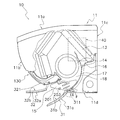
- FIG. 1 is a cross-sectional view of the air conditioning indoor unit 10 when operation is stopped according to an embodiment of the present invention.
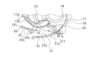
- FIG. 2 is a cross-sectional view of the air conditioning indoor unit 10 during operation. 1 and 2, the air conditioning indoor unit 10 is a wall-hanging type, and a main body casing 11, an indoor heat exchanger 13, an indoor fan 14, a bottom frame 16, and a control unit 40 are mounted thereon.
- the main body casing 11 has a top surface portion 11a, a front panel 11b, a back plate 11c, and a lower horizontal plate 11d, and houses an indoor heat exchanger 13, an indoor fan 14, a bottom frame 16, and a control unit 40 therein. .
- the top surface part 11a is located in the upper part of the main body casing 11, and the inlet (not shown) is provided in the front part of the top surface part 11a.
- the front panel 11b constitutes the front part of the indoor unit, and has a flat shape without a suction port. Further, the upper end of the front panel 11b is rotatably supported by the top surface portion 11a, and can operate in a hinged manner.
- the indoor heat exchanger 13 and the indoor fan 14 are attached to the bottom frame 16.
- the indoor heat exchanger 13 exchanges heat with the passing air.
- the indoor heat exchanger 13 has an inverted V-shape in which both ends are bent downward in a side view, and the indoor fan 14 is located below the indoor heat exchanger 13.
- the indoor fan 14 is a cross-flow fan, blows air taken in from the room against the indoor heat exchanger 13 and then blows it into the room.
- An air outlet 15 is provided at the lower part of the main body casing 11.
- a wind direction adjusting blade 31 that changes the direction of conditioned air blown from the blower outlet 15 is rotatably attached to the blower outlet 15.
- the wind direction adjusting blade 31 is driven by a motor (not shown) and can change the direction of the conditioned air, and can also open and close the air outlet 15.
- the wind direction adjusting blade 31 can take a plurality of postures having different inclination angles.
- a Coanda blade 32 is provided in the vicinity of the air outlet 15.
- the Coanda blade 32 can take a posture inclined in the front-rear direction by a motor (not shown), and is accommodated in the accommodating portion 130 provided in the front panel 11b when the operation is stopped.
- the Coanda blade 32 can take a plurality of postures having different inclination angles. Further, the air outlet 15 is connected to the inside of the main body casing 11 by the air outlet channel 18. The blowout channel 18 is formed along the scroll 17 of the bottom frame 16 from the blowout port 15.
- the indoor air is sucked into the indoor fan 14 through the suction port and the indoor heat exchanger 13 by the operation of the indoor fan 14, and blown out from the blower outlet 15 through the blowout passage 18 from the indoor fan 14.
- the control unit 40 is located on the right side of the indoor heat exchanger 13 and the indoor fan 14 when the main body casing 11 is viewed from the front panel 11b, and controls the rotational speed of the indoor fan 14, the wind direction adjusting blade 31 and the Coanda blade 32. Perform motion control.
- the depth of the depression in this region is set so as to match the thickness dimension of the Coanda blade 32, and constitutes a housing portion 130 in which the Coanda blade 32 is housed.
- the surface of the accommodating part 130 is also a gentle circular curved surface.
- the blower outlet 15 is formed in the lower part of the main body casing 11, and is a rectangular opening which makes a horizontal direction (direction orthogonal to the paper surface of FIG. 1) a long side.
- the lower end of the blower outlet 15 is in contact with the front edge of the lower horizontal plate 11d, and the virtual plane connecting the lower end and the upper end of the blower outlet 15 is inclined forward and upward.
- Scroll 17 The scroll 17 is a partition wall curved so as to face the indoor fan 14 and is a part of the bottom frame 16.
- the end F of the scroll 17 reaches the vicinity of the periphery of the air outlet 15.
- the air passing through the blowout flow path 18 travels along the scroll 17 and is sent in the tangential direction of the end F of the scroll 17. Therefore, if there is no wind direction adjusting blade 31 at the air outlet 15, the air direction of the conditioned air blown out from the air outlet 15 is a direction substantially along the tangent L 0 of the terminal end F of the scroll 17.
- the vertical wind direction adjusting plate 20 includes a plurality of blade pieces 201 and a connecting rod 203 that connects the plurality of blade pieces 201. Further, the vertical air direction adjusting plate 20 is disposed nearer the indoor fan 14 than the air direction adjusting blades 31 in the blowout flow path 18. The plurality of blade pieces 201 swing left and right around a state perpendicular to the longitudinal direction as the connecting rod 203 horizontally reciprocates along the longitudinal direction of the outlet 15. The connecting rod 203 is horizontally reciprocated by a motor (not shown). (2-5) Wind direction adjusting blade 31 The wind direction adjusting blade 31 has an area that can block the air outlet 15.
- the outer side surface 31 a is finished to have a gentle circular curved surface that protrudes outwardly as if it is an extension of the curved surface of the front panel 11 b. Further, the inner side surface 31b (see FIG. 2) of the wind direction adjusting blade 31 also forms an arcuate curved surface substantially parallel to the outer surface.
- the wind direction adjusting blade 31 has a rotation shaft 311 at the lower end.
- the rotating shaft 311 is connected to the rotating shaft of a stepping motor (not shown) fixed to the main body casing 11 in the vicinity of the lower end of the air outlet 15.
- the rotation shaft 311 rotates counterclockwise when viewed from the front in FIG. 1, so that the upper end of the airflow direction adjusting blade 31 moves away from the upper end side of the outlet 15 to open the outlet 15.
- the rotation shaft 311 rotates in the clockwise direction in FIG. 1, the upper end of the wind direction adjusting blade 31 operates so as to approach the upper end side of the outlet 15 to close the outlet 15.
- the conditioned air blown out from the air outlet 15 flows substantially along the inner side surface 31 b of the airflow direction adjusting blade 31.
- the conditioned air blown out substantially along the tangential direction of the terminal end F of the scroll 17 has its wind direction changed slightly upward by the wind direction adjusting blade 31.
- the Coanda blade 32 is stored in the storage unit 130 while the air-conditioning operation is stopped or in an operation in the normal blowing mode described later.
- the Coanda blade 32 moves away from the accommodating portion 130 by rotating.
- the rotation shaft 321 of the Coanda blade 32 is provided in the vicinity of the lower end of the housing portion 130 and inside the main body casing 11 (a position above the upper wall of the blowout flow path 18).
- the rotating shaft 321 is connected with a predetermined interval. Therefore, as the rotation shaft 321 rotates and the Coanda blade 32 moves away from the housing portion 130 of the front surface of the indoor unit, the height position of the lower end of the Coanda blade 32 rotates so as to become lower.
- the accommodating portion 130 is provided outside the air passage, and the entire Coanda blade 32 is accommodated outside the air passage when being accommodated.
- the rest may be accommodated in the air passage (for example, the upper wall portion of the air passage).
- the rotating shaft 321 rotates counterclockwise in the front view of FIG. 1, the upper and lower ends of the Coanda blades 32 are separated from the housing portion 130 while drawing an arc.
- the shortest distance between the accommodation unit 130 on the front surface of the indoor unit is larger than the shortest distance between the lower end and the accommodation unit 130. That is, the Coanda blade 32 is controlled so as to move away from the front surface of the indoor unit as it goes forward.
- the rotation shaft 321 rotates in the clockwise direction in the front view of FIG. 1
- the Coanda blade 32 approaches the storage unit 130 and is finally stored in the storage unit 130.
- the operating state of the Coanda blade 32 includes a state where the Coanda blade 32 is housed in the storage unit 130, a posture rotated and tilted forward and upward, a posture rotated and substantially horizontal, and a posture rotated and tilted forward and downward. is there.
- the outer surface 32a of the Coanda blade 32 is finished to a gentle circular curved surface that protrudes outwardly as if it is an extension of the gentle circular curved surface of the front panel 11b.
- the inner side surface 32 b of the Coanda blade 32 is finished to have an arcuate curved surface that follows the surface of the housing portion 130.
- the dimension in the longitudinal direction of the Coanda blade 32 is set to be equal to or larger than the dimension in the longitudinal direction of the wind direction adjusting blade 31. This is because all the conditioned air whose direction is adjusted by the wind direction adjusting blade 31 is received by the Coanda blade 32, and its purpose is to prevent the conditioned air from the side of the Coanda blade 32 from short-circuiting.
- Controlling the direction of conditioned air The air conditioning indoor unit of the present embodiment, as means for controlling the direction of conditioned air, is a normal blowing mode in which only the wind direction adjusting blade 31 is rotated to adjust the direction of conditioned air, and the wind direction.
- the adjustment vane 31 and the Coanda vane 32 are rotated, and the Coanda effect utilization mode in which the conditioned air is made into a Coanda airflow along the outer surface 32a of the Coanda vane 32 by the Coanda effect is provided. Since the postures of the wind direction adjusting blade 31 and the Coanda blade 32 change for each air blowing direction in each mode, each posture will be described with reference to the drawings. It should be noted that the blowing direction can be selected by the user via a remote controller or the like. It is also possible to control the mode change and the blowing direction to be automatically changed.
- FIG. 3A is a side view of the wind direction adjusting blade 31 and the Coanda blade 32 when the conditioned air is normally forward blown.
- the control unit 40 rotates the wind direction adjusting blade 31 to a position where the inner side surface 31b of the wind direction adjusting blade 31 becomes substantially horizontal.
- wing 31 has comprised the circular arc curved surface like this embodiment, the wind direction adjustment blade
- FIG. 3B is a side view of the wind direction adjusting blade 31 and the Coanda blade 32 when the conditioned air is normally forward down blown.
- the control unit 40 rotates the wind direction adjusting blade 31 until the tangent at the front end E1 of the inner side surface 31b of the wind direction adjusting blade 31 becomes lower than the horizontal. As a result, the conditioned air is in a front lower blowing state.
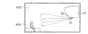
- FIG. 6A is a side view of the air conditioning indoor unit installation space showing the wind direction of the conditioned air by the vertical swing of the wind direction adjusting blade 31.
- the wind direction adjustment as shown in FIG. 6A is a wind direction adjustment by a so-called auto louver function, which is also implemented in a conventional product, and is used as a means for repeating the operation of applying or not applying the wind to the human body 400.
- Coanda (effect) means that if there is a wall near the flow of gas or liquid, it flows in the direction along the wall surface even if the direction of the flow is different from the direction of the wall. It is a phenomenon to try (Asakura Shoten “Dictionary of Law”).
- the Coanda utilization mode includes “Coanda airflow front blowing” and “Coanda airflow ceiling blowing” using this Coanda effect.
- the direction of the conditioned air and the direction of the Coanda airflow differ depending on how the reference position is determined, but an example is shown below.
- FIG. 4A is a conceptual diagram showing the direction of conditioned air and the direction of Coanda airflow. In FIG.
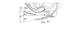
- the Coanda blade 32 and the wind direction adjusting blade 31 need to be equal to or less than a predetermined opening angle, and the above relationship is established so that both blades (31, 32) are within the range. Is established. Thereby, as shown in FIG. 4A, after the wind direction of the conditioned air is changed to D1 by the wind direction adjusting blade 31, it is further changed to D2 by the Coanda effect.
- FIG. 4B is a conceptual diagram illustrating an example of an opening angle between the wind direction adjusting blade 31 and the Coanda blade 32.
- the wind direction adjusting blade 31 and the Coanda blade 32 have an inner angle formed by the tangent of the end F of the scroll 17 and the Coanda blade 32 and the tangent of the end F of the scroll 17. It is preferable to take a posture that satisfies the condition that it is larger than the inner angle formed by the wind direction adjusting blade 31. 5A (the inner angle R2 formed by the tangent line L0 of the terminal end F of the scroll 17 and the Coanda blade 32 when the Coanda airflow is blown forward and the tangent line L0 of the terminal end F of the scroll 17 and the airflow direction adjusting blade 31 are formed.
- Comparison diagram with inner angle R1) and FIG. 5B inner angle R2 formed between tangent L0 of end F of scroll 17 and Coanda blade 32 when Coanda airflow ceiling is blown, tangent L0 of end F of scroll 17 and wind direction adjusting blade 31) (Refer to the comparison figure with the internal angle R1).
- 3C is a side view of the wind direction adjusting blade 31 and the Coanda blade 32 during the Coanda airflow forward blow.
- the control unit 40 moves the airflow direction adjustment blade 31 until the tangent L1 at the front end E1 of the inner side surface 31b of the airflow direction adjustment blade 31 becomes lower than the horizontal. Rotate.
- the control unit 40 rotates the Coanda blade 32 until the outer surface 32a of the Coanda blade 32 becomes substantially horizontal.
- the Coanda blade 32 is rotated until the tangent L2 at the front end E2 of the outer surface 32a becomes substantially horizontal. That is, as shown in FIG. 5A, the inner angle R2 formed by the tangent line L0 and the tangent line L2 is larger than the inner angle R1 formed by the tangent line L0 and the tangent line L1.
- the conditioned air adjusted by the wind direction adjusting blade 31 to the front lower blowing becomes a flow attached to the outer surface 32a of the Coanda blade 32 by the Coanda effect, and changes to a Coanda airflow along the outer surface 32a. Therefore, even if the tangent L1 direction at the front end E1 of the airflow direction adjusting blade 31 is the front lower blowing, the tangential L2 direction at the front end E2 of the Coanda blade 32 is horizontal, so that the conditioned air is generated by the Coanda effect by the Coanda effect. It blows off in the tangent L2 direction at the front end E2 of the outer side surface 32a, that is, in the horizontal direction.
- 3D is a side view of the wind direction adjusting blade 31 and the Coanda blade 32 when the Coanda airflow ceiling is blown.
- the control unit 40 rotates the airflow direction adjusting blade 31 until the tangent L1 at the front end E1 of the inner side surface 31b of the airflow direction adjusting blade 31 becomes horizontal.
- the control part 40 rotates the Coanda blade
- the conditioned air adjusted to be blown horizontally by the airflow direction adjusting blade 31 becomes a flow adhered to the outer surface 32a of the Coanda blade 32 by the Coanda effect, and changes to a Coanda airflow along the outer surface 32a.
- the tangential L2 direction at the front end E2 of the Coanda blade 32 is forward upward blowing, so that the conditioned air is generated by the Coanda effect by the Coanda effect. It blows out in the tangent L2 direction at the front end E2 of the outer side surface 32a, that is, the ceiling direction. Since the front end portion of the Coanda blade 32 protrudes outward from the air outlet 15, the Coanda airflow reaches further away. Furthermore, since the tip of the Coanda blade 32 is located above the air outlet 15, the generation of an airflow that passes above the Coanda blade 32 is suppressed, and the upward induction of the Coanda airflow is hardly inhibited. .
- the Coanda blades 32 are separated from the front surface of the indoor unit and the inclination becomes gentle, and the conditioned air becomes more susceptible to the Coanda effect in front of the front panel 11b.
- the size in the longitudinal direction of the Coanda blade 32 is not less than the size in the longitudinal direction of the wind direction adjusting blade 31. Therefore, all of the conditioned air whose wind direction is adjusted by the wind direction adjusting blade 31 can be received by the Coanda blade 32, and the effect of preventing the conditioned air from being short-circuited from the side of the Coanda blade 32 is also achieved.
- FIG. 6B is a side view of the air-conditioning indoor unit installation space showing the wind direction of the conditioned air when the wind direction adjusting blade 31 faces downward.
- FIG. 6C is a side view of the air conditioning indoor unit installation space showing the wind direction of the Coanda airflow when the Coanda blade 32 is in the ceiling blowing posture.
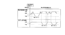
- FIG. 7 is a flowchart showing the operation of the wind direction adjusting blade 31 and the Coanda blade 32 during the fluctuation airflow A control.
- the wind direction adjusting blade 31 swings between an upper limit position and a lower limit position with an operation of waiting at an intermediate position interposed therebetween.
- the control unit 40 irregularly changes the time during which the wind direction adjusting blade 31 waits at the intermediate position (hereinafter referred to as the intermediate position standby time), and thereby the wind moving away from the wind approaching the resident. Since the combination of the two is irregularly changed, it is possible to provide residents with various winds.
- the Coanda blade 32 swings between the upper limit position and the lower limit position. As shown in FIG.
- the airflow direction adjustment blade 31 swings between the upper limit position and the intermediate position.
- One pattern and a second pattern in which the wind direction adjusting blade 31 swings between the intermediate position and the lower limit position while the Coanda blade 32 stands by at the upper limit position are included.
- the operation in which the Coanda blade 32 moves from the upper limit position to the lower limit position is synchronized with the timing at which the wind direction adjustment blade 31 moves from the intermediate position to the upper limit position.
- the operation of the Coanda blade 32 moving from the lower limit position to the upper limit position is synchronized with the timing when the wind direction adjusting blade 31 is moved from the upper limit position to the intermediate position.
- the Coanda blade 32 is controlled so as to be in the upper limit position, so that no Coanda airflow is generated.
- the intermediate position standby time of the wind direction adjusting blade 31 is irregularly changed, the time during which the Coanda airflow is not generated is irregularly changed, and the intervals at which the wind is unexpectedly changed are irregularly changed by the residents.
- a variety of winds can be provided.
- the wind direction adjusting blade 31 is in the intermediate position and the Coanda blade 32 is in the upper limit position. Time is measured as standby time.
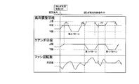
- FIG. 8 is a flowchart showing the operation of the wind direction adjusting blade 31 and the Coanda blade 32 and the fan rotation speed of the indoor fan 14 during the fluctuation airflow B control.
- the operation of the wind direction adjusting blade 31 and the Coanda blade 32 is the same as that during the fluctuation airflow A control, but the fan rotational speed of the indoor fan 14 is changed according to the operation of the wind direction adjusting blade 31 and the Coanda blade 32. Is different from the fluctuation airflow A control.
- the fan rotation speed of the indoor fan 14 is increased to a predetermined value.
- the predetermined value refers to the number of rotations of the fan for ensuring the minimum air volume that allows the wind separated from the Coanda blades 32 to reach the occupant. Therefore, when the fan rotation speed of the indoor fan 14 rises to a predetermined value at the time when the Coanda blade 32 starts moving from the upper limit position to the lower limit position, the airflow is peeled off from the Coanda blade 32 and directed toward the resident. Unexpected wind is realized because the airflow surely reaches the residents.
- the wind direction adjusting blade 31 starts moving to the lower limit position after the first standby time tf1 has elapsed, and after reaching the lower limit position, it stops at the lower limit position for a predetermined time and starts moving again to the intermediate position.
- the wind direction adjusting blade 31 that has moved to the intermediate position then waits for the second waiting time tf2 and then starts to move to the upper limit position.
- the Coanda blade 32 starts to move to the lower limit position in synchronization.
- the Coanda blade 32 that has reached the lower limit position waits there for a predetermined time and then starts to rise toward the upper limit position.
- the wind direction adjusting blade 31 that has reached the upper limit position also stands by for a certain period of time, and starts moving toward the intermediate position synchronously when the Coanda blade 32 starts moving to the upper limit position.
- the wind direction adjusting blade 31 that has reached the intermediate position waits there. During this time, the Coanda blade 32 reaches the upper limit position.
- the control unit 40 measures the standby time starting from the time when the wind direction adjusting blade 31 reaches the intermediate position and the Coanda blade 32 reaches the upper limit position.
- the wind direction adjusting blade 31 starts moving to the upper limit position after waiting for the second waiting time tf3. At this time, the Coanda blade 32 starts to move to the lower limit position in synchronization.
- the Coanda blade 32 that has reached the lower limit position waits there for a predetermined time and then starts to rise toward the upper limit position.
- the wind direction adjusting blade 31 that has already reached the upper limit position is also waiting there for a certain period of time, but in synchronization with the Coanda blade 32 starting to move to the upper limit position, it moves toward the intermediate position. Start. Thereafter, it operates according to wind direction patterns with different standby times set in advance.
- control part 40 can also change each of the time for which the wind direction adjustment blade
- the fan rotation speed of the indoor fan 14 repeatedly rises and falls irregularly according to a preset fluctuation amount pattern. However, while the Coanda blade 32 is at the lower limit position, the fan rotation speed is irregularly changed within a predetermined value or more. Then, when the Coanda blade 32 starts to move from the lower limit position to the upper limit position and the Coanda blade 32 reaches the upper limit position, the restriction is released and the fan rotation speed is changed irregularly.
- the fan rotation speed of the indoor fan 14 in accordance with the operation of the wind direction adjusting blade 31 and the Coanda blade 32, low-frequency fluctuations and swells are realized, and conditioned air that is closer to natural wind is occupant. Can be provided.
- the fan speed is controlled to be a predetermined value or more.
- the control unit 40 controls the operation of the Coanda blade during fluctuation airflow control, and executes a mode including a Coanda generation state in which the Coanda airflow is generated and a Coanda non-generation state in which the Coanda airflow is not generated. Therefore, when the fluctuation airflow control is performed, the flow of the wind is diversified by suddenly generating the Coanda airflow, and the conditioned air closer to the natural wind can be provided to the occupant.
- control unit 40 changes the air volume of the conditioned air during fluctuation air flow control, the conditioned air becomes an air flow that is closer to the natural wind by changing the air volume in addition to the wind direction, providing a comfortable air-conditioned space for the residents. can do.
- the control unit 40 changes the air volume of the conditioned air to a predetermined value during the time period in which the Coanda airflow is generated, that is, the period during which the Coanda blade 32 moves from the upper limit position to the lower limit position, waits, and moves to the upper limit position again To do. Therefore, the conditioned air at the moment when the Coanda effect is eliminated can surely reach the occupant, thus realizing an “unexpected wind”.
- (6) Modified Example In the above embodiment, both the fluctuation airflow A control and the fluctuation airflow B control, the Coanda generation state in which the Coanda airflow is generated by irregularly swinging the wind direction adjusting blade 31 and the Coanda blade 32, and the Coanda. Although the mode including the Coanda non-generation state that does not generate the airflow is realized, it is not limited to this. Below, the modification of fluctuation airflow control is demonstrated.
- FIG. 9 is a flowchart showing the operation of the wind direction adjusting blade 31 and the Coanda blade 32 during fluctuation airflow control in the first modification.
- the fluctuation airflow control in the first modification is performed by oscillating only the airflow direction adjusting blade 31 and the time zone in which the A mode in which the airflow direction adjusting blade 31 and the Coanda blade 32 are swung to generate the fluctuating airflow is executed. It is characterized by mixing the time zone in which the B mode for generating the fluctuation airflow is executed.
- the Coanda blade 32 swings between the upper limit position and the lower limit position.
- the controller 40 irregularly changes the time during which the Coanda blade 32 waits at the upper limit position, and accordingly, the time during which the Coanda airflow is not generated irregularly changes, and the wind blows unexpectedly to the resident. Since the intervals are changed irregularly, various winds can be provided by residents.
- the Coanda blade 32 is moved to the fully closed position, the Coanda airflow is not always generated regardless of the upper and lower limit positions of the wind direction adjusting blade 31.
- the wind direction adjusting blade 31 swings between the upper limit position and the lower limit position with the operation of waiting at the intermediate position interposed therebetween.
- the control unit 40 irregularly changes the time during which the wind direction adjusting blade 31 waits at the intermediate position, and thereby, the combination of the wind approaching the resident and the wind moving away is irregularly switched. So it can provide residents with a variety of winds.
- FIG. 10 is a flowchart showing the operation of the wind direction adjusting blade 31 and the Coanda blade 32 during fluctuation airflow control in the second modification.
- the fluctuation airflow control in the second modification includes a C mode in which only the Coanda blade 32 is swung to generate a fluctuation airflow in addition to the A mode and the B mode of the fluctuation airflow control in the first modification. It is characteristic that it is made to do.
- the Coanda blade 32 is instantaneously adsorbed on the lower surface of the Coanda blade 32 and becomes a Coanda airflow. A state where it is not suitable for the resident and a state where the Coanda effect is canceled and the resident is again directed are repeated. That is, a certain “unexpected wind” can be generated.
- conditioned air close to natural wind can be provided to the occupant, so that it is useful not only for wall-mounted air conditioning indoor units but also for air purifiers.
Landscapes
- Engineering & Computer Science (AREA)
- Chemical & Material Sciences (AREA)
- Combustion & Propulsion (AREA)
- Mechanical Engineering (AREA)
- General Engineering & Computer Science (AREA)
- Air Conditioning Control Device (AREA)
- Air-Flow Control Members (AREA)
Priority Applications (3)
| Application Number | Priority Date | Filing Date | Title |
|---|---|---|---|
| ES13837777T ES2807904T3 (es) | 2012-09-13 | 2013-08-29 | Unidad interior de aire acondicionado |
| CN201380047536.2A CN104620058B (zh) | 2012-09-13 | 2013-08-29 | 空调室内机 |
| EP13837777.5A EP2918930B1 (fr) | 2012-09-13 | 2013-08-29 | Unité intérieure de climatisation |
Applications Claiming Priority (2)
| Application Number | Priority Date | Filing Date | Title |
|---|---|---|---|
| JP2012-201807 | 2012-09-13 | ||
| JP2012201807A JP5408318B1 (ja) | 2012-09-13 | 2012-09-13 | 空調室内機 |
Publications (1)
| Publication Number | Publication Date |
|---|---|
| WO2014042012A1 true WO2014042012A1 (fr) | 2014-03-20 |
Family
ID=50202631
Family Applications (1)
| Application Number | Title | Priority Date | Filing Date |
|---|---|---|---|
| PCT/JP2013/073149 Ceased WO2014042012A1 (fr) | 2012-09-13 | 2013-08-29 | Unité intérieure de climatisation |
Country Status (5)
| Country | Link |
|---|---|
| EP (1) | EP2918930B1 (fr) |
| JP (1) | JP5408318B1 (fr) |
| CN (1) | CN104620058B (fr) |
| ES (1) | ES2807904T3 (fr) |
| WO (1) | WO2014042012A1 (fr) |
Cited By (1)
| Publication number | Priority date | Publication date | Assignee | Title |
|---|---|---|---|---|
| CN114364921A (zh) * | 2019-09-17 | 2022-04-15 | 大金工业株式会社 | 空调室内机和空调机 |
Families Citing this family (7)
| Publication number | Priority date | Publication date | Assignee | Title |
|---|---|---|---|---|
| JP6065076B1 (ja) * | 2015-09-10 | 2017-01-25 | ダイキン工業株式会社 | 壁掛け式の空調室内機 |
| JP6869109B2 (ja) * | 2017-05-31 | 2021-05-12 | ダイキン インダストリーズ (タイランド) リミテッドDaikin Industries (Thailand) Ltd. | 空気調和機 |
| EP4001790B1 (fr) | 2019-09-17 | 2024-03-20 | Daikin Industries, Ltd. | Unité intérieure pour climatiseur |
| GB2588220B (en) | 2019-10-17 | 2022-08-03 | Dyson Technology Ltd | A fan assembly |
| KR102517611B1 (ko) * | 2020-11-13 | 2023-04-03 | 엘지전자 주식회사 | 공기조화기 |
| CN114110950B (zh) * | 2021-11-29 | 2023-04-07 | 海信空调有限公司 | 空调器及其控制方法和装置和存储介质 |
| EP4394262B1 (fr) * | 2022-12-26 | 2026-03-25 | LG Electronics Inc. | Unité intérieure de climatiseur |
Citations (4)
| Publication number | Priority date | Publication date | Assignee | Title |
|---|---|---|---|---|
| JPH06265168A (ja) * | 1993-03-11 | 1994-09-20 | Mitsubishi Heavy Ind Ltd | 空気調和機における吹出風の制御方法 |
| JP2001041538A (ja) | 1999-08-04 | 2001-02-16 | Matsushita Electric Ind Co Ltd | 空気調和機の風向制御方法 |
| JP2007192480A (ja) * | 2006-01-20 | 2007-08-02 | Sharp Corp | 空気調和機 |
| JP2013117368A (ja) * | 2011-10-31 | 2013-06-13 | Daikin Industries Ltd | 空調室内機 |
Family Cites Families (6)
| Publication number | Priority date | Publication date | Assignee | Title |
|---|---|---|---|---|
| JP4017483B2 (ja) * | 2002-09-25 | 2007-12-05 | シャープ株式会社 | 空気調和機 |
| JP3686963B2 (ja) * | 2003-11-28 | 2005-08-24 | シャープ株式会社 | 空気調和機 |
| CN100588884C (zh) * | 2005-10-31 | 2010-02-10 | 乐金电子(天津)电器有限公司 | 空调室内机出风口的多向异步运转叶片的连接结构 |
| JP4033885B2 (ja) * | 2006-09-11 | 2008-01-16 | シャープ株式会社 | 空気調和機 |
| CN101614438A (zh) * | 2008-06-23 | 2009-12-30 | 乐金电子(天津)电器有限公司 | 柜式空调室内机出风导流片结构 |
| AU2010299201B2 (en) * | 2009-09-28 | 2013-07-25 | Daikin Industries, Ltd. | Control device |
-
2012
- 2012-09-13 JP JP2012201807A patent/JP5408318B1/ja active Active
-
2013
- 2013-08-29 WO PCT/JP2013/073149 patent/WO2014042012A1/fr not_active Ceased
- 2013-08-29 ES ES13837777T patent/ES2807904T3/es active Active
- 2013-08-29 EP EP13837777.5A patent/EP2918930B1/fr active Active
- 2013-08-29 CN CN201380047536.2A patent/CN104620058B/zh active Active
Patent Citations (4)
| Publication number | Priority date | Publication date | Assignee | Title |
|---|---|---|---|---|
| JPH06265168A (ja) * | 1993-03-11 | 1994-09-20 | Mitsubishi Heavy Ind Ltd | 空気調和機における吹出風の制御方法 |
| JP2001041538A (ja) | 1999-08-04 | 2001-02-16 | Matsushita Electric Ind Co Ltd | 空気調和機の風向制御方法 |
| JP2007192480A (ja) * | 2006-01-20 | 2007-08-02 | Sharp Corp | 空気調和機 |
| JP2013117368A (ja) * | 2011-10-31 | 2013-06-13 | Daikin Industries Ltd | 空調室内機 |
Cited By (2)
| Publication number | Priority date | Publication date | Assignee | Title |
|---|---|---|---|---|
| CN114364921A (zh) * | 2019-09-17 | 2022-04-15 | 大金工业株式会社 | 空调室内机和空调机 |
| CN114364921B (zh) * | 2019-09-17 | 2023-10-24 | 大金工业株式会社 | 空调室内机和空调机 |
Also Published As
| Publication number | Publication date |
|---|---|
| JP2014055746A (ja) | 2014-03-27 |
| EP2918930B1 (fr) | 2020-06-24 |
| CN104620058B (zh) | 2016-06-15 |
| EP2918930A4 (fr) | 2016-10-26 |
| CN104620058A (zh) | 2015-05-13 |
| JP5408318B1 (ja) | 2014-02-05 |
| EP2918930A1 (fr) | 2015-09-16 |
| ES2807904T3 (es) | 2021-02-24 |
Similar Documents
| Publication | Publication Date | Title |
|---|---|---|
| JP5403125B2 (ja) | 空調室内機 | |
| JP5408318B1 (ja) | 空調室内機 | |
| JP5408228B2 (ja) | 空調室内機 | |
| JP5408227B2 (ja) | 空調室内機 | |
| JP5365675B2 (ja) | 空調室内機 | |
| WO2013065436A1 (fr) | Unité de climatisation d'intérieur | |
| JP5536158B2 (ja) | 空調室内機 | |
| JP5408319B1 (ja) | 空調室内機 | |
| JP5403046B2 (ja) | 空調室内機 | |
| JP5338895B2 (ja) | 空調室内機 | |
| JP5408317B1 (ja) | 空調室内機 | |
| JP6077245B2 (ja) | 空調室内機 | |
| JP5413535B2 (ja) | 空調室内機 | |
| JP5772589B2 (ja) | 空調室内機 | |
| JP2013139913A (ja) | 空調室内機 | |
| JP2014070810A (ja) | 空調室内機 | |
| JP5783041B2 (ja) | 空調室内機 | |
| JP2008122001A (ja) | 空気調和機 |
Legal Events
| Date | Code | Title | Description |
|---|---|---|---|
| 121 | Ep: the epo has been informed by wipo that ep was designated in this application |
Ref document number: 13837777 Country of ref document: EP Kind code of ref document: A1 |
|
| NENP | Non-entry into the national phase |
Ref country code: DE |
|
| WWE | Wipo information: entry into national phase |
Ref document number: 2013837777 Country of ref document: EP |