WO2014045596A1 - ズームレンズシステムおよび撮像装置 - Google Patents
ズームレンズシステムおよび撮像装置 Download PDFInfo
- Publication number
- WO2014045596A1 WO2014045596A1 PCT/JP2013/005594 JP2013005594W WO2014045596A1 WO 2014045596 A1 WO2014045596 A1 WO 2014045596A1 JP 2013005594 W JP2013005594 W JP 2013005594W WO 2014045596 A1 WO2014045596 A1 WO 2014045596A1
- Authority
- WO
- WIPO (PCT)
- Prior art keywords
- lens
- lens group
- positive
- fixed
- object side
- Prior art date
- Legal status (The legal status is an assumption and is not a legal conclusion. Google has not performed a legal analysis and makes no representation as to the accuracy of the status listed.)
- Ceased
Links
Images



Classifications
-
- G—PHYSICS
- G02—OPTICS
- G02B—OPTICAL ELEMENTS, SYSTEMS OR APPARATUS
- G02B15/00—Optical objectives with means for varying the magnification
- G02B15/14—Optical objectives with means for varying the magnification by axial movement of one or more lenses or groups of lenses relative to the image plane for continuously varying the equivalent focal length of the objective
- G02B15/145—Optical objectives with means for varying the magnification by axial movement of one or more lenses or groups of lenses relative to the image plane for continuously varying the equivalent focal length of the objective having five groups only
- G02B15/1455—Optical objectives with means for varying the magnification by axial movement of one or more lenses or groups of lenses relative to the image plane for continuously varying the equivalent focal length of the objective having five groups only the first group being negative
- G02B15/145527—Optical objectives with means for varying the magnification by axial movement of one or more lenses or groups of lenses relative to the image plane for continuously varying the equivalent focal length of the objective having five groups only the first group being negative arranged -+-++
-
- G—PHYSICS
- G02—OPTICS
- G02B—OPTICAL ELEMENTS, SYSTEMS OR APPARATUS
- G02B13/00—Optical objectives specially designed for the purposes specified below
- G02B13/18—Optical objectives specially designed for the purposes specified below with lenses having one or more non-spherical faces, e.g. for reducing geometrical aberration
Definitions
- the present invention relates to a zoom lens system and an image pickup apparatus using the same.
- Japanese Patent Publication No. 2003-232993 (reference 1) describes providing a refractive optical system having intermediate imaging that can maintain good imaging performance even with a small number of lenses. Therefore, this document 1 includes an imaging lens group that forms an intermediate image of an object, a field lens group that is disposed in the vicinity of the formation position of the intermediate image, and a relay lens group that re-images the intermediate image. It is described that the focal length f1 of the imaging lens group and the focal length f of the refractive optical system satisfy the conditional expression “1 ⁇
- One aspect of the present invention includes a first optical system that forms light from the object side as an intermediate image, and a second optical system that forms light from the intermediate image as a final image,
- the first optical system includes a fixed lens group that does not move when zooming
- the second optical system includes a zoom lens group that moves when zooming, and the fixed lens group is closest to the object side.
- a zoom lens system including a first negative meniscus lens disposed on the object side and having a convex surface facing the object side.
- the first optical system is a wide-angle lens group in which the first negative meniscus lens is disposed closest to the object side with the convex surface facing the object side.
- the light beam that has passed through the first negative meniscus lens is guided to the opposite side across the optical axis to form an inverted image as an intermediate image, and is finally imaged by the second optical system.
- the zoom lens group included in the second optical system moves, and the wide-angle fixed lens group that constitutes the first optical system does not move. Since the first optical system that forms the intermediate image can be fixed, the imaging position of the intermediate image can also be fixed.
- the image formation position of the intermediate image does not change with zooming, and the intermediate image surface can be prevented from being positioned in the lens surface or the lens at each zoom position from the wide-angle end to the telephoto end. Accordingly, it is possible to suppress foreign matters such as scratches and dust on the lens surface from appearing in the final image.
- the imaging position of the intermediate image can be fixed by fixing the first optical system
- the back focus of the first optical system can be designed to be short. For this reason, it is easy to widen the angle and the overall length of the first optical system can be shortened, so that the overall length of the zoom lens system is also easily shortened.
- the zooming mechanism can be simplified because the drive mechanism for zooming can be concentrated in the vicinity of the second optical system. Therefore, a compact wide-angle zoom lens system capable of forming a clear final image can be provided.
- the fixed lens group includes a first fixed lens group having a negative refractive power including a first negative meniscus lens, and a second fixed lens having a positive refractive power disposed on the final image side of the first fixed lens group. It is desirable to include a lens group and a diaphragm disposed between the first fixed lens group and the second fixed lens group. It is easy to position the entrance pupil of the zoom lens system on the object side of the stop, and to easily approach the first fixed lens group. For this reason, it is easy to achieve a wide angle without increasing the lens diameter of the first negative meniscus lens.
- the second fixed lens group includes a first cemented lens disposed closest to the object side, and the first cemented lens includes a biconvex positive lens and a biconcave negative lens disposed in order from the object side. It is desirable. By arranging the first cemented lens on the final image side of the entrance pupil, chromatic aberration can be effectively corrected. More preferably, the first cemented lens includes a biconvex positive lens disposed on the final image side of the negative lens.
- the second optical system includes a third fixed lens unit having a negative refractive power that is disposed on the object side of the variable power lens unit and does not move when zooming.
- the imaging position of the intermediate image can be fixed by fixing the first optical system, and the intermediate image is fixed to the fixed lens by disposing a third fixed lens group between the intermediate image and the variable power lens group. It can be sandwiched between the group and the third fixed lens group. Therefore, it is possible to more effectively suppress the intermediate image plane from being positioned on the lens surface or in the lens during zooming.
- the distance on the optical axis between the intermediate image and the lens surface closest to the object side of the third fixed lens group is the distance on the optical axis between the intermediate image and the lens surface closest to the final image side of the fixed lens group. Shorter than that.
- the zoom lens system by fixing each lens group sandwiching the intermediate image from the object side and the final image side, the distance between the intermediate image and the lens surface closest to the object side of the third fixed lens group is reduced.
- the relationship of being shorter than the distance between the intermediate image and the lens surface on the most final image side of the fixed lens group can be maintained. Because of this relationship, the front focus of the third fixed lens group can be made shorter than the back focus of the fixed lens group, so the lens diameter of the third fixed lens group can be easily reduced.
- the third fixed lens group includes a first positive meniscus lens that is disposed closest to the final image side and has a convex surface facing the final image side, and includes a refractive index n1 of the first negative meniscus lens and a first positive meniscus lens.
- the refractive index n3 of the lens preferably satisfies the following conditions (1.1) to (1.3). n1 ⁇ 1.65 (1.1) n3 ⁇ 1.90 (1.2) 0.82 ⁇ n1 / n3 ⁇ 1.00 (1.3)
- this zoom lens system can be designed so that the negative distortion aberration DistLf and the positive distortion aberration DistLb satisfy the following conditions (1.4) and (1.5).
- the third fixed lens group includes a second cemented lens disposed closest to the final image side, and the second cemented lens is a second negative lens having a convex surface directed toward the final image side disposed in order from the object side. It is composed of a meniscus lens and a first positive meniscus lens, and the Abbe number ⁇ 32 of the second negative meniscus lens and the Abbe number ⁇ 33 of the first positive meniscus lens satisfy the following conditions (A) and (B): Is desirable. 45.0 ⁇ ⁇ 32 ⁇ 55.0 (A) 15.0 ⁇ ⁇ 33 ⁇ 25.0 (B)
- condition (A) is set to give a weak dispersion force (low dispersion) to the second negative meniscus lens, and a strong dispersion force (high dispersion) is given to the first positive meniscus lens.
- Condition (B) is set in Therefore, chromatic aberration can be favorably corrected from the visible region to the near-infrared region by combining the second negative meniscus lens with low dispersion and the first positive meniscus lens with high dispersion.
- the variable power lens group includes a first moving lens group having positive refractive power that moves from the final image side to the object side when zooming from the wide-angle end to the telephoto end, and a final image side of the first moving lens group. And a second moving lens group having a positive refractive power that moves from the final image side to the object side when zooming from the wide-angle end to the telephoto end, and the first moving lens group is closest to the final image side.
- the first positive lens is arranged, and the second moving lens group is constituted by a second positive lens, a first negative lens, and a third positive lens arranged in order from the object side.
- the partial dispersion ratio Pgf41 of the positive lens, the partial dispersion ratio Pgf51 of the second positive lens, the partial dispersion ratio Pgf52 of the first negative lens, and the partial dispersion ratio Pgf53 of the third positive lens satisfy the following conditions ( It is desirable to satisfy 2.1) to (2.4). 0.53 ⁇ Pgf41 ⁇ 0.55 (2.1) 0.53 ⁇ Pgf53 ⁇ 0.55 (2.2) 0.55 ⁇ Pgf51 ⁇ 0.58 (2.3) 0.58 ⁇ Pgf52 ⁇ 0.66 (2.4)
- Conditions (2.1) and (2.2) are as follows: partial dispersion ratio Pgf41 of the first positive lens closest to the object side of the first moving lens group and the first image side closest to the final image side of the second moving lens group. 3 shows that the partial dispersion ratio Pgf53 of the positive lens No. 3 is set low with substantially equal balance. Furthermore, the condition (2.3) sets the partial dispersion ratio Pgf51 of the second positive lens slightly higher than the conditions (2.1) and (2.2), and the condition (2.4) It shows that the partial dispersion ratio Pgf52 of the negative lens is set to be the highest in the variable power lens group.
- the chromatic aberration of the zoom lens system can be corrected more satisfactorily by bonding the first positive lens and a lens having a positive refractive power that satisfies the condition (2.1).
- One of the different aspects of the present invention is an imaging apparatus having the zoom lens system and an imaging device disposed at a position where a final image of the zoom lens system is formed.
- FIG. 3 is a diagram illustrating lens data of the zoom lens system according to the first embodiment. It is a figure which shows the numerical values of the zoom lens system which concerns on 1st Embodiment, (a) shows basic data, (b) shows zoom data, (c) shows aspherical data.
- FIG. 2A is an aberration diagram of the zoom lens system according to the first embodiment, and FIG. 3A is an aberration diagram at a wide angle end, and FIG.
- FIG. 2B is an aberration diagram at a telephoto end.
- FIG. 6 is an aberration diagram of the first optical system of the zoom lens system according to the first embodiment. It is a figure which shows schematic structure of the zoom lens system which concerns on 2nd Embodiment, and an imaging device using the same, (a) shows the lens arrangement
- FIG. 6 is a diagram illustrating lens data of a zoom lens system according to a second embodiment. It is a figure which shows various numerical values of the zoom lens system which concerns on 2nd Embodiment, (a) shows basic data, (b) shows zoom data, (c) shows aspherical data.
- FIG. 4A is an aberration diagram of the zoom lens system according to the second embodiment
- FIG. 4A is an aberration diagram at a wide angle end
- FIG. 4B is an aberration diagram at a telephoto end
- FIG. 10 is an aberration diagram of the first optical system of the zoom lens system according to the second embodiment.
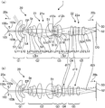
- FIG. 1 shows a schematic configuration of a zoom lens system 10 according to a first embodiment of the present invention and an imaging apparatus 1 using the same
- FIG. 1A shows a lens arrangement at a wide angle end (WIDE).
- FIG. 1B shows the lens arrangement at the telephoto end (TELE).
- An imaging device (camera) 1 is arranged at a position where a zoom lens system 10 and a final image 52 of the zoom lens system 10 are formed, and a CCD, a CMOS, or the like that converts the final image 52 into an electrical signal (image data).
- An imaging device (imaging device, image sensor) 50 is arranged at a position where a zoom lens system 10 and a final image 52 of the zoom lens system 10 are formed, and a CCD, a CMOS, or the like that converts the final image 52 into an electrical signal (image data).
- An imaging device (imaging device, image sensor) 50 is arranged at a position where a zoom lens system 10 and a final image 52 of the zoom lens
- the zoom lens system 10 includes, in order from the object side 10a, a first optical system (primary imaging lens group) 11 that forms light from the object side 10a as an intermediate image 51, and finally outputs light from the intermediate image 51.
- a second optical system (secondary imaging lens group, relay lens group) 12 that forms an image 52 is formed.
- the primary imaging lens group 11 is a fixed wide-angle lens group (fixed lens group) 11a that does not move when the zoom lens system 10 changes magnification.
- the fixed wide-angle lens group 11a of this example includes, in order from the object side 10a, a first fixed lens group G1 having a negative refractive power, a diaphragm (aperture stop) St, and a second fixed lens group G2 having a positive refractive power. It consists of and.
- the relay lens group 12 includes, in order from the object side 10a, a third fixed lens group G3 having a negative refractive power that does not move when zooming, and a zoom lens group 12a that moves when zooming. Yes.
- the variable power lens group 12a includes a first moving lens group G4 having a positive refractive power that moves when zooming and a second moving lens group G5 having a positive refractive power that moves when zooming.
- An imaging device 50 is disposed on the final image side (image side) 10b of the relay lens group 12 with a cover glass CG interposed therebetween.
- the imaging device 50 can provide image data to a host device such as a personal computer, or can transmit the image data to an external information processing apparatus via a computer network or the like.
- the zoom lens system 10 is a re-imaging type lens system (two-stage optical system) composed of a primary imaging lens group 11 and a relay lens group 12, and the entire glass lenses L11 and L12 are made of thirteen. , L21 to L25, L31, L32, L41, and L51 to L53.
- the zoom lens system 10 forms an intermediate image 51 between the primary imaging lens group 11 and the relay lens group 12 and forms a final image 52 on the final image side 10 b of the relay lens group 12. That is, in this zoom lens system 10, the primary imaging lens group 11 is incident from one region (upper half region, first region) 100a on the first surface 100x including the optical axis 100. The light beam is collected in the direction along the optical axis 100 by the first fixed lens group G1 and converged by the second fixed lens group G2 to be opposite to the first region 100a, that is, the first axis including the optical axis 100. An image is formed as an intermediate image (inverted image) 51 inverted on the other region (lower half region, second region) 100b with respect to the surface 100x.
- the intermediate image 51 can be formed as a final image (upright image) 52 in which the top, bottom, left and right of the intermediate image 51 are reversed.
- the first fixed lens group G1 closest to the object side 10a is a lens group having a negative refractive power as a whole, and is arranged in order from the object side 10a.
- the first negative lens group G1 has the convex surface S1 facing the object side 10a. It comprises a meniscus lens L11 and a negative meniscus lens L12 that is convex on the object side 10a.
- the first negative meniscus lens L11 is a lens having the largest effective diameter (aperture) in the zoom lens system 10, but its effective diameter is as very compact as 16.50 mm.
- Both surfaces of the negative meniscus lens L12, that is, the convex surface S3 on the object side 10a and the concave surface S4 on the final image side 10b are aspherical surfaces.
- the second fixed lens group G2 disposed across the stop St on the final image side 10b of the first fixed lens group G1 is a lens group having a positive refractive power as a whole, and is sequentially disposed from the object side 10a.
- the first cemented lens LB1 includes a biconvex positive lens L21, a biconcave negative lens L22, and a biconvex positive lens L23, which are arranged in order from the object side 10a.
- Both surfaces of the positive lens L24 that is, the convex surface S9 on the object side 10a and the convex surface S10 on the final image side 10b are aspherical surfaces.
- a distance dmia (d12a) on the optical axis 100 between the concave surface S12 on the final image side 10b of the positive meniscus lens L25 and the intermediate image 51 is 3.34 mm.
- the third fixed lens group G3 arranged with the intermediate image 51 sandwiched between the final image side 10b of the second fixed lens group G2 is a lens group having a negative refractive power as a whole, and sequentially from the object side 10a. It is composed of a biconcave negative lens L31 and a first positive meniscus lens L32 having a convex surface S16 facing the final image side 10b. A distance dmib (d12b) on the optical axis 100 between the intermediate image 51 and the concave surface S13 on the object side 10a of the negative lens L31 is 2.10 mm.
- the first moving lens group G4 disposed on the final image side 10b of the third fixed lens group G3 is a lens group having a positive refractive power as a whole, and is a biconvex positive lens (first positive lens). ) L41.
- the second moving lens group G5 arranged on the most final image side 10b is a lens group having a positive refractive power as a whole, and is arranged in order from the object side 10a, and is a positive meniscus lens convex toward the object side 10a.
- Both surfaces of the positive lens L53 that is, the convex surface S23 on the object side 10a and the convex surface S24 on the final image side 10b are aspherical surfaces.
- This zoom lens system 10 is composed of 13 lenses L11 to L53 grouped into five lens groups G1 to G5 having refractive powers of negative-positive-negative-positive-positive in order from the object side 10a.
- This is a lens system capable of zooming.
- the fixed lens groups G1 to G3 do not move, that is, the imaging magnification of the incident light beam is not changed, and each of the moving lens groups G4 and G5 is changed. Moves monotonously along the optical axis 100 from the final image side 10b to the object side 10a, thereby changing the imaging magnification of the intermediate image 51.
- the moving distance of the first moving lens group G4 (8.84 mm in this example) is slightly longer than the moving distance of the second moving lens group G5 (7.41 mm in this example).
- Focus adjustment can be performed by any one of the first fixed lens group G1, the positive meniscus lens L25 of the second fixed lens group G2, and the zoom lens system 10 as a whole.
- a light beam captured from a wide range (wide angle) via the convex surface S ⁇ b> 1 of the first negative meniscus lens L ⁇ b> 11 disposed closest to the object side 10 a is optically reflected by the primary imaging lens group 11. Then, it is guided to the opposite side (second region 100b) across 100 and once formed as an inverted image 51 (intermediate imaging), then the relay lens group 12 sandwiches the optical axis 100 and the original side (first side). 1 to the final region (secondary image formation) as an erect image 52.
- the final image 52 has a region (first first) incident on the optical axis 100 when light incident from the off-axis (off-axis light beam) crosses the optical axis 100 twice (intersects and strides). An image is formed in the region 100a). For this reason, it is not necessary to refract a wide-angle off-axis light beam only in the first region 100a and form a final image, so that it is easy to widen the angle while suppressing the occurrence of various aberrations. Therefore, it is easy to improve the degree of freedom of design.
- the moving lens groups G ⁇ b> 4 and G ⁇ b> 5 included in the relay lens group 12 on the final image side 10 b with respect to the intermediate image 51 move during zooming, and the primary imaging lens group that forms the intermediate image 51. 11 is fixed without moving.
- the imaging position of the intermediate image 51 can be fixed without moving. Therefore, the image formation position of the intermediate image 51 does not vary with zooming, and the intermediate image surface can be prevented from being positioned on the lens surface or in the lens at each zoom position from the wide-angle end to the telephoto end. For this reason, it is possible to prevent foreign matters such as scratches and dust on the lens surface from appearing in the final image 52.
- the second and third fixed lens groups G2 and G3 that are closest to the intermediate image 51 and sandwich the intermediate image 51 from both sides in the direction of the optical axis 100 are fixed. Therefore, it is easy to ensure the sealing performance in the vicinity of the intermediate image 51, and the contamination of foreign matter in the vicinity of the intermediate image 51 can be suppressed.
- the imaging position of the intermediate image 51 can be fixed by fixing the primary imaging lens group 11, the back focus of the primary imaging lens group 11 can be extremely shortened. For this reason, it is easy to widen the angle and the overall length of the first optical system can be shortened, so that the overall length of the zoom lens system is also easily shortened.
- the driving mechanism for zooming can be concentrated in the vicinity of the first and second moving lens groups G4 and G5, so that driving for zooming is possible.
- the shape of the mechanism and cam can be simplified. Therefore, the overall length of the zoom lens system 10 can be easily shortened, and the lens size on the object side 10a can be easily reduced. Therefore, it is possible to provide the zoom lens system 10 that can secure a wide viewing angle with a compact configuration and can form a bright and clear final image 52.
- a diaphragm St is disposed between the first fixed lens group G1 and the second fixed lens group G2.
- the entrance pupil EP of the zoom lens system 10 can be positioned on the object side 10a of the stop St, and the entrance pupil EP can be easily brought close to the first fixed lens group G1. Therefore, in the zoom lens system 10, since the primary imaging lens group 11 has the entrance pupil EP inside, the first fixed lens group G1 on the object side 10a with respect to the entrance pupil EP has a negative refractive power. It can be configured with only a lens. For this reason, it is possible to effectively widen and widen the angle of view without increasing the lens diameters of the first negative meniscus lens L11 and the negative meniscus lens L12.
- the position of the entrance pupil EP represents the distance from the convex surface S1 on the object side 10a of the first negative meniscus lens L11 arranged closest to the object side 10a, and is 5.46 mm in this example.
- a positive meniscus lens L25 having the highest refractive index (1.96 in this example) in the zoom lens system 10 is disposed on the most final image side 10b of the primary imaging lens group 11. ing. For this reason, it is easy to refract the principal ray of the incident light beam toward the optical axis 100 (inward) by the strong refractive power of the positive meniscus lens L25. Therefore, the back focus of the primary imaging lens group 11, that is, the distance d12a between the concave surface S12 of the positive meniscus lens L25 and the intermediate image 51 can be shortened. For this reason, it is easy to shorten the overall length of the zoom lens system 10.
- the off-axis light beam is easily collected toward the optical axis 100 by the high-refractive-index positive meniscus lens L25, it is possible to suppress an increase in the image height of the intermediate image 51. For this reason, it is easy to reduce the size of the negative lens L31 that is disposed closest to the object side 10a of the relay lens group 12 and receives the light beam diverging from the intermediate image 51 first.
- the distance d12b (2.10 mm in this example) between the intermediate image 51 and the concave surface S13 of the negative lens L31 is the distance d12a (in this example) between the concave surface S12 of the positive meniscus lens L25 and the intermediate image 51. It can be arranged to be shorter than 3.34 mm). Accordingly, since the front focus of the third fixed lens group G3 can be made shorter than the back focus of the second fixed lens group G2, the lens diameter of the third fixed lens group G3 can be easily reduced, and the entire length of the zoom lens system 10 can be reduced. Is also easy to shorten.
- the lens group G3 is disposed so that the convex surface S16 of the first positive meniscus lens L32 is in the opposite direction, and further the refractive index n1 of the first negative meniscus lens L11 and the refractive index of the first positive meniscus lens L32.
- n3 is designed to satisfy the following conditions (1.1) to (1.3).
- the upper limit of condition (1.1) is preferably 2.25, more preferably 2.10, and even more preferably 2.00.
- the lower limit of condition (1.1) is preferably 1.75, and more preferably 1.85.
- the upper limit of condition (1.2) is preferably 2.25, more preferably 2.10, and even more preferably 2.00.
- the lower limit of condition (1.2) is preferably 1.92, and more preferably 1.94.
- the primary imaging lens group 11 is generated by disposing a double-sided aspheric negative meniscus lens L 12 and a double-sided aspheric positive lens L 24 in the primary imaging lens group 11.
- An increase in the negative distortion aberration DistLf can be suppressed. Therefore, the negative distortion aberration DistLf is easily canceled by the positive distortion aberration DistLb generated in the relay lens group 12.
- the zoom lens system 10 is designed such that the negative distortion aberration DistLf and the positive distortion aberration DistLb satisfy the following conditions (1.4) and (1.5).
- the partial dispersion ratio Pgf41 of the positive lens L41, the partial dispersion ratio Pgf51 of the positive meniscus lens L51, the partial dispersion ratio Pgf52 of the negative lens L52, and the partial dispersion ratio Pgf53 of the positive lens L53 are as follows. It is designed to satisfy the conditions (2.1) to (2.4). 0.53 ⁇ Pgf41 ⁇ 0.55 (2.1) 0.53 ⁇ Pgf53 ⁇ 0.55 (2.2) 0.55 ⁇ Pgf51 ⁇ 0.58 (2.3) 0.58 ⁇ Pgf52 ⁇ 0.66 (2.4)
- the partial dispersion ratio Pgf41 of the positive lens L41 and the partial dispersion ratio Pgf53 of the positive lens L53 are low with a substantially equal balance.
- the partial dispersion ratio Pgf51 of the positive meniscus lens L51 is set slightly higher than the conditions (2.1) and (2.2)
- the condition (2.4 ) The partial dispersion ratio Pgf52 of the negative lens L52 is set highest in the variable power lens group 12a.
- both surfaces S23 and S24 of the positive lens L53 which is the final lens disposed on the most final image side 10b of the moving lens group G4, aspherical, it is possible to satisfactorily correct spherical aberration and field curvature, An increase in the number of sheets can be suppressed, and an increase in the total optical length can be suppressed.
- the upper limit of conditions (2.1) and (2.2) is preferably 0.54.
- the upper limit of condition (2.3) is preferably 0.57, and the lower limit of condition (2.3) is preferably 0.56.
- the upper limit of condition (2.4) is preferably 0.64, and the lower limit of condition (2.4) is preferably 0.60.
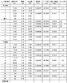
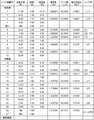
- FIG. 2 shows lens data of each lens of the zoom lens system 10.
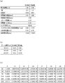
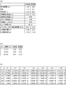
- FIG. 3 shows various numerical values of the zoom lens system 10.
- Ri is a radius of curvature (mm) of each lens (each lens surface) arranged in order from the object side 10a
- di is a distance (mm) between each lens surface arranged in order from the object side 10a
- Di is an object.
- nd is the refractive index (d line) of each lens arranged in sequence from the object side 10a
- ⁇ d is the Abbe number of each lens arranged in sequence from the object side 10a ( d line).
- Flat indicates a plane.
- 3A the entrance pupil position indicates the distance from the convex surface S1 of the first negative meniscus lens L11
- the exit pupil position indicates the distance from the image plane of the imaging device 50. The same applies to the following embodiments.
- the air distance (distance) d16 between the third fixed lens group G3 and the first moving lens group G4, and the first moving lens The air gap d18 between the group G4 and the second moving lens group G5 and the air gap d24 between the second moving lens group G5 and the cover glass CG change.
- both surfaces S3 and S4 of the negative meniscus lens L12, both surfaces S9 and S10 of the positive lens L24, and both surfaces S23 and S24 of the positive lens L53 are aspheric.
- the aspherical surface has coefficients K, C1, and C2 in FIG. 3C, where X is the coordinate in the optical axis direction, Y is the coordinate perpendicular to the optical axis, the light traveling direction is positive, and R is the paraxial radius of curvature.
- C3, C4, C5 and C6 are represented by the following formula. “En” means “10 to the power of n”.
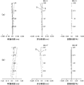
- FIG. 4 shows aberration diagrams of the zoom lens system 10
- FIG. 4 (a) shows aberration diagrams at the wide-angle end
- FIG. 4 (b) shows aberration diagrams at the telephoto end
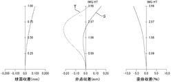
- FIG. 5 shows aberration diagrams of the primary imaging lens group 11 of the zoom lens system 10.
- the spherical aberration indicates a wavelength of 656 nm (dotted line), a wavelength of 587 nm (solid line), a wavelength of 546 nm (one-dot chain line), a wavelength of 486 nm (two-dot chain line), and a wavelength of 435 nm (one-dot long chain line).
- Astigmatism indicates the aberrations of the tangential ray (T) and the sagittal ray (S), respectively.
- the vertical axis represents the image height (IMG HT). The same applies to the following embodiments.
- the zoom lens system 10 of the present example is capable of photographing a bright and clear image with a wide angle of 126 degrees at the wide angle end and an F value of 2.0, and is a zoom lens system with a good balance between performance and cost. 10 is an example.
- FIG. 6 shows a schematic configuration of a zoom lens system 20 according to a second embodiment of the present invention and an imaging apparatus 1 using the same, and FIG. 6A shows a lens arrangement at the wide angle end (WIDE). FIG. 6B shows the lens arrangement at the telephoto end (TELE).
- WIDE wide angle end
- TELE telephoto end
- the zoom lens system 20 also forms a primary image forming lens group 21 that forms light from the object side 20a as an intermediate image 51 and a light from the intermediate image 51 as a final image 52 in order from the object side 20a. And a relay lens group 22.
- the primary imaging lens group 21 of this example is also a fixed wide-angle lens group 21a that does not move when the zoom lens system 20 changes magnification.
- This fixed wide-angle lens group 21a also has, in order from the object side 20a, a first fixed lens group G1 having a negative refractive power that does not move when zooming, a stop St, and a positive refractive power that does not move when zooming.
- the relay lens group 22 of the present example also includes, in order from the object side 20a, a third fixed lens group G3 having a negative refractive power that does not move when zooming, and a zoom lens group 22a that moves when zooming. It is configured.
- the zoom lens group 22a also includes a first moving lens group G4 having a positive refractive power that moves when zooming and a second moving lens group G5 having a positive refractive power that moves when zooming. It is configured.
- This zoom lens system 20 is composed of a total of 14 glass lenses L11, L12, L21 to L25, L31 to L33, L41, and L51 to L53.
- the third fixed lens group G3 is composed of a biconcave negative lens L31 and a second cemented second lens (balsam lens) LB2 which are arranged in order from the object side 20a.
- the second cemented lens LB2 is arranged in order from the object side 20a, the second negative meniscus lens L32 having the convex surface S16 facing the final image side 20b, and the first positive meniscus having the convex surface S17 facing the final image side 20b.
- a meniscus lens L33 Since the configurations of the other lens groups G1, G2, G4, and G5 and the shapes of the lenses included in the lens groups G1, G2, G4, and G5 are the same as those in the first embodiment, common reference numerals are used. A description of each lens will be omitted.
- the second cemented lens LB2 is disposed on the final image side 20b from the intermediate image 51, and the Abbe number ⁇ 32 of the second negative meniscus lens L32 and the first positive meniscus lens L33 are arranged.
- the Abbe number ⁇ 33 is designed to satisfy the following conditions (A) and (B). 45.0 ⁇ ⁇ 32 ⁇ 55.0 (A) 15.0 ⁇ ⁇ 33 ⁇ 25.0 (B)
- the condition (A) is set to give a weak dispersion force (low dispersion) to the second negative meniscus lens L32, and a strong dispersion force (high dispersion) is applied to the first positive meniscus lens L33.
- the condition (B) is set to give Therefore, by combining the low dispersion second negative meniscus lens L32 and the high dispersion first positive meniscus lens L33, chromatic aberration can be favorably corrected from the visible region to the near infrared region. Therefore, even if the incident light is in a wavelength band including near infrared rays and the chromatic aberration correction by the first cemented lens LB1 disposed on the object side 20a from the intermediate image 51 is insufficient, the second cemented lens.
- the chromatic aberration correction capability can be reinforced by LB2. If the range of the conditions (A) and (B) is exceeded, the longitudinal chromatic aberration increases and it becomes difficult to correct the aberration.
- FIG. 7 shows lens data of each lens of the zoom lens system 20.
- FIG. 8 shows various numerical values of the zoom lens system 20.
- the air distance d17 between the third fixed lens group G3 and the first moving lens group G4, the first moving lens group G4, The air gap d19 between the second moving lens group G5 and the air gap d25 between the second moving lens group G5 and the cover glass CG change.
- both surfaces S3 and S4 of the negative meniscus lens L12, both surfaces S9 and S10 of the positive lens L24, and both surfaces S24 and S25 of the positive lens L53 are aspherical surfaces.
- the values of the equations giving the above conditions (1.1) to (1.3), (2.1) to (2.4), (A) and (B) of the zoom lens system 20 of the present example are as follows: It becomes as follows.
- the refractive index n3 indicates the refractive index of the first positive meniscus lens L33.
- FIG. 9 shows aberration diagrams of the zoom lens system 20
- FIG. 9 (a) shows aberration diagrams at the wide-angle end
- FIG. 9 (b) shows aberration diagrams at the telephoto end
- FIG. 10 is an aberration diagram of the primary imaging lens group 21 of the zoom lens system 20. As shown in FIGS. 9 and 10, both aberrations are well corrected and a clear image can be taken. For spherical aberration, a wavelength of 900 nm is indicated by a broken line.
- the zoom lens system 20 of the present example has a wide angle of 117 degrees at the wide angle end, a bright F value of 1.8, and can capture a clear image from the visible region to the near infrared region.
- the zoom lens system 20 is suitable for high-sensitivity cameras (imaging devices) that do not have an autofocus mechanism or the like and are used for various purposes such as day-and-night monitoring purposes or observation, disaster prevention, measurement, and recording. Can provide.
- the first optical system and / or the second optical system of the zoom lens system may have at least one reflecting surface (mirror). Further, the inventions defined in the claims may be mutually independent for each claim.
Landscapes
- Physics & Mathematics (AREA)
- General Physics & Mathematics (AREA)
- Optics & Photonics (AREA)
- Lenses (AREA)
Priority Applications (2)
| Application Number | Priority Date | Filing Date | Title |
|---|---|---|---|
| EP13839860.7A EP2899581B1 (de) | 2012-09-20 | 2013-09-20 | Zoomobjektivsystem und bildaufnahmevorrichtung |
| JP2014536608A JP6227539B2 (ja) | 2012-09-20 | 2013-09-20 | ズームレンズシステムおよび撮像装置 |
Applications Claiming Priority (2)
| Application Number | Priority Date | Filing Date | Title |
|---|---|---|---|
| JP2012206720 | 2012-09-20 | ||
| JP2012-206720 | 2012-09-20 |
Publications (1)
| Publication Number | Publication Date |
|---|---|
| WO2014045596A1 true WO2014045596A1 (ja) | 2014-03-27 |
Family
ID=50340931
Family Applications (1)
| Application Number | Title | Priority Date | Filing Date |
|---|---|---|---|
| PCT/JP2013/005594 Ceased WO2014045596A1 (ja) | 2012-09-20 | 2013-09-20 | ズームレンズシステムおよび撮像装置 |
Country Status (3)
| Country | Link |
|---|---|
| EP (1) | EP2899581B1 (de) |
| JP (3) | JP6227539B2 (de) |
| WO (1) | WO2014045596A1 (de) |
Cited By (18)
| Publication number | Priority date | Publication date | Assignee | Title |
|---|---|---|---|---|
| JP2015060062A (ja) * | 2013-09-18 | 2015-03-30 | キヤノン株式会社 | 結像光学系および画像投射装置 |
| JP2016006442A (ja) * | 2014-06-20 | 2016-01-14 | オリンパス株式会社 | 変倍リレー光学系、及び、撮像装置 |
| JP2016143032A (ja) * | 2015-02-05 | 2016-08-08 | コニカミノルタ株式会社 | 投影光学系及びプロジェクター |
| US9509893B2 (en) | 2014-03-31 | 2016-11-29 | Panasonic Intellectual Property Management Co., Ltd. | Imaging device and analyzing apparatus using the imaging device |
| JP2017102239A (ja) * | 2015-12-01 | 2017-06-08 | コニカミノルタ株式会社 | 投影光学系及びプロジェクター |
| WO2017195387A1 (ja) * | 2016-05-13 | 2017-11-16 | 株式会社タムロン | 観察光学系、観察撮像装置、観察撮像システム、結像レンズ系及び観察光学系の調整方法 |
| WO2017195857A1 (ja) * | 2016-05-13 | 2017-11-16 | パナソニックIpマネジメント株式会社 | 結像光学系及び画像投写装置 |
| JP2017211480A (ja) * | 2016-05-25 | 2017-11-30 | 富士フイルム株式会社 | 結像光学系、投写型表示装置、および、撮像装置 |
| JP2018036381A (ja) * | 2016-08-30 | 2018-03-08 | 富士フイルム株式会社 | ズームレンズ、撮像装置、および投写型表示装置 |
| JP2018180447A (ja) * | 2017-04-20 | 2018-11-15 | コニカミノルタ株式会社 | 投影光学系及び投影装置 |
| JP2019095684A (ja) * | 2017-11-27 | 2019-06-20 | セイコーエプソン株式会社 | 投写光学系および投写型画像表示装置 |
| JP2020052385A (ja) * | 2018-09-25 | 2020-04-02 | 富士フイルム株式会社 | 結像光学系、投写型表示装置、および撮像装置 |
| JP2020077008A (ja) * | 2015-12-01 | 2020-05-21 | コニカミノルタ株式会社 | 投影光学系及びプロジェクター |
| WO2020152942A1 (ja) * | 2019-01-25 | 2020-07-30 | パナソニックIpマネジメント株式会社 | 光学系、画像投写装置および撮像装置 |
| JP2020115236A (ja) * | 2020-04-15 | 2020-07-30 | 富士フイルム株式会社 | 結像光学系、投写型表示装置、および、撮像装置 |
| JPWO2021256477A1 (de) * | 2020-06-16 | 2021-12-23 | ||
| CN114600027A (zh) * | 2019-10-29 | 2022-06-07 | 富士胶片株式会社 | 变倍光学系统及摄像装置 |
| WO2022176234A1 (ja) * | 2021-02-16 | 2022-08-25 | パナソニックIpマネジメント株式会社 | 光学系、画像投写装置および撮像装置 |
Families Citing this family (1)
| Publication number | Priority date | Publication date | Assignee | Title |
|---|---|---|---|---|
| CN113534424B (zh) * | 2021-07-15 | 2024-08-23 | 舜宇光学(中山)有限公司 | 变焦镜头 |
Citations (6)
| Publication number | Priority date | Publication date | Assignee | Title |
|---|---|---|---|---|
| JPH02267511A (ja) * | 1989-04-10 | 1990-11-01 | Nikon Corp | ズーム光学系 |
| JP2003232993A (ja) | 2002-02-08 | 2003-08-22 | Nikon Corp | 屈折光学系 |
| JP2008536175A (ja) * | 2005-04-08 | 2008-09-04 | パナビジョン・インターナショナル・リミテッド・パートナーシップ | 簡素化したズーム構造を持つワイドレンジで広角の複合ズーム |
| JP2011007824A (ja) * | 2009-06-23 | 2011-01-13 | Canon Inc | 光学装置 |
| JP2011509415A (ja) * | 2007-12-04 | 2011-03-24 | ブラックアイ オプティクス,エルエルシー | 固定群内に液体レンズを有する望遠タイプのズームレンズ |
| JP2011130014A (ja) * | 2009-12-15 | 2011-06-30 | Canon Inc | 撮像装置 |
Family Cites Families (5)
| Publication number | Priority date | Publication date | Assignee | Title |
|---|---|---|---|---|
| US7283309B2 (en) * | 2004-08-20 | 2007-10-16 | Panavision International, L.P. | Wide-range, wide-angle, rotatable compound zoom |
| US7224535B2 (en) * | 2005-07-29 | 2007-05-29 | Panavision International, L.P. | Zoom lens system |
| JP5389390B2 (ja) * | 2008-07-25 | 2014-01-15 | オリンパス株式会社 | 観察装置 |
| JP5871743B2 (ja) * | 2012-07-31 | 2016-03-01 | キヤノン株式会社 | 結像光学系、及びそれを用いた投射型画像表示装置、撮像装置 |
| JP6198862B2 (ja) * | 2016-01-14 | 2017-09-20 | キヤノン株式会社 | 結像光学系、及びそれを用いた投射型画像表示装置、撮像装置 |
-
2013
- 2013-09-20 EP EP13839860.7A patent/EP2899581B1/de active Active
- 2013-09-20 WO PCT/JP2013/005594 patent/WO2014045596A1/ja not_active Ceased
- 2013-09-20 JP JP2014536608A patent/JP6227539B2/ja active Active
-
2017
- 2017-08-28 JP JP2017163065A patent/JP6427241B2/ja active Active
-
2018
- 2018-10-26 JP JP2018201518A patent/JP6615974B2/ja active Active
Patent Citations (6)
| Publication number | Priority date | Publication date | Assignee | Title |
|---|---|---|---|---|
| JPH02267511A (ja) * | 1989-04-10 | 1990-11-01 | Nikon Corp | ズーム光学系 |
| JP2003232993A (ja) | 2002-02-08 | 2003-08-22 | Nikon Corp | 屈折光学系 |
| JP2008536175A (ja) * | 2005-04-08 | 2008-09-04 | パナビジョン・インターナショナル・リミテッド・パートナーシップ | 簡素化したズーム構造を持つワイドレンジで広角の複合ズーム |
| JP2011509415A (ja) * | 2007-12-04 | 2011-03-24 | ブラックアイ オプティクス,エルエルシー | 固定群内に液体レンズを有する望遠タイプのズームレンズ |
| JP2011007824A (ja) * | 2009-06-23 | 2011-01-13 | Canon Inc | 光学装置 |
| JP2011130014A (ja) * | 2009-12-15 | 2011-06-30 | Canon Inc | 撮像装置 |
Cited By (37)
| Publication number | Priority date | Publication date | Assignee | Title |
|---|---|---|---|---|
| US9958652B2 (en) | 2013-09-18 | 2018-05-01 | Canon Kabushiki Kaisha | Imaging optical system, image projection optical system and image projection apparatus |
| JP2015060062A (ja) * | 2013-09-18 | 2015-03-30 | キヤノン株式会社 | 結像光学系および画像投射装置 |
| US9509893B2 (en) | 2014-03-31 | 2016-11-29 | Panasonic Intellectual Property Management Co., Ltd. | Imaging device and analyzing apparatus using the imaging device |
| JP2016006442A (ja) * | 2014-06-20 | 2016-01-14 | オリンパス株式会社 | 変倍リレー光学系、及び、撮像装置 |
| US9958660B2 (en) | 2014-06-20 | 2018-05-01 | Olympus Corporation | Imaging apparatus including variable power relay optical system |
| JP2016143032A (ja) * | 2015-02-05 | 2016-08-08 | コニカミノルタ株式会社 | 投影光学系及びプロジェクター |
| JP2017102239A (ja) * | 2015-12-01 | 2017-06-08 | コニカミノルタ株式会社 | 投影光学系及びプロジェクター |
| JP2020077008A (ja) * | 2015-12-01 | 2020-05-21 | コニカミノルタ株式会社 | 投影光学系及びプロジェクター |
| WO2017195857A1 (ja) * | 2016-05-13 | 2017-11-16 | パナソニックIpマネジメント株式会社 | 結像光学系及び画像投写装置 |
| JP2017203935A (ja) * | 2016-05-13 | 2017-11-16 | 株式会社タムロン | 観察光学系、観察撮像装置、観察撮像システム、結像レンズ系及び観察光学系の調整方法 |
| WO2017195387A1 (ja) * | 2016-05-13 | 2017-11-16 | 株式会社タムロン | 観察光学系、観察撮像装置、観察撮像システム、結像レンズ系及び観察光学系の調整方法 |
| JPWO2017195857A1 (ja) * | 2016-05-13 | 2019-03-14 | パナソニックIpマネジメント株式会社 | 結像光学系及び画像投写装置 |
| US10921571B2 (en) | 2016-05-13 | 2021-02-16 | Tamron Co., Ltd. | Observation optical system, observation imaging device, observation imaging system, image forming lens system, and method of adjusting observation optical system |
| JP2017211480A (ja) * | 2016-05-25 | 2017-11-30 | 富士フイルム株式会社 | 結像光学系、投写型表示装置、および、撮像装置 |
| US10816777B2 (en) | 2016-05-25 | 2020-10-27 | Fujifilm Corporation | Imaging optical system, projection-type display apparatus, and imaging apparatus |
| JP2018036381A (ja) * | 2016-08-30 | 2018-03-08 | 富士フイルム株式会社 | ズームレンズ、撮像装置、および投写型表示装置 |
| JP7019961B2 (ja) | 2017-04-20 | 2022-02-16 | コニカミノルタ株式会社 | 投影光学系及び投影装置 |
| CN112859300A (zh) * | 2017-04-20 | 2021-05-28 | 柯尼卡美能达株式会社 | 投影光学系统以及投影装置 |
| JP2018180447A (ja) * | 2017-04-20 | 2018-11-15 | コニカミノルタ株式会社 | 投影光学系及び投影装置 |
| JP2019095684A (ja) * | 2017-11-27 | 2019-06-20 | セイコーエプソン株式会社 | 投写光学系および投写型画像表示装置 |
| JP2020052385A (ja) * | 2018-09-25 | 2020-04-02 | 富士フイルム株式会社 | 結像光学系、投写型表示装置、および撮像装置 |
| CN113348396A (zh) * | 2019-01-25 | 2021-09-03 | 松下知识产权经营株式会社 | 光学系统、图像投影装置以及摄像装置 |
| WO2020152942A1 (ja) * | 2019-01-25 | 2020-07-30 | パナソニックIpマネジメント株式会社 | 光学系、画像投写装置および撮像装置 |
| US20210341715A1 (en) * | 2019-01-25 | 2021-11-04 | Panasonic Intellectual Property Management Co., Ltd. | Optical system, image projection apparatus, and imaging apparatus |
| JPWO2020152942A1 (ja) * | 2019-01-25 | 2021-12-02 | パナソニックIpマネジメント株式会社 | 光学系、画像投写装置および撮像装置 |
| US12253659B2 (en) | 2019-01-25 | 2025-03-18 | Panasonic Intellectual Property Management Co., Ltd. | Optical system, image projection apparatus, and imaging apparatus |
| JP7417834B2 (ja) | 2019-01-25 | 2024-01-19 | パナソニックIpマネジメント株式会社 | 光学系、画像投写装置および撮像装置 |
| CN114600027B (zh) * | 2019-10-29 | 2023-11-14 | 富士胶片株式会社 | 变倍光学系统及摄像装置 |
| CN114600027A (zh) * | 2019-10-29 | 2022-06-07 | 富士胶片株式会社 | 变倍光学系统及摄像装置 |
| JP2020115236A (ja) * | 2020-04-15 | 2020-07-30 | 富士フイルム株式会社 | 結像光学系、投写型表示装置、および、撮像装置 |
| WO2021256477A1 (ja) * | 2020-06-16 | 2021-12-23 | 株式会社nittoh | 中間像が内部に形成される光学系 |
| JP7627959B2 (ja) | 2020-06-16 | 2025-02-07 | 株式会社nittoh | 中間像が内部に形成される光学系 |
| JPWO2021256477A1 (de) * | 2020-06-16 | 2021-12-23 | ||
| US12411323B2 (en) | 2020-06-16 | 2025-09-09 | Nittoh Inc. | Optical system having intermediate image formed therein |
| WO2022176234A1 (ja) * | 2021-02-16 | 2022-08-25 | パナソニックIpマネジメント株式会社 | 光学系、画像投写装置および撮像装置 |
| JPWO2022176234A1 (de) * | 2021-02-16 | 2022-08-25 | ||
| JP7829144B2 (ja) | 2021-02-16 | 2026-03-13 | パナソニックIpマネジメント株式会社 | 光学系、画像投写装置および撮像装置 |
Also Published As
| Publication number | Publication date |
|---|---|
| JP2017204011A (ja) | 2017-11-16 |
| EP2899581A4 (de) | 2016-04-20 |
| JPWO2014045596A1 (ja) | 2016-08-18 |
| EP2899581A1 (de) | 2015-07-29 |
| EP2899581B1 (de) | 2017-08-23 |
| JP2019015987A (ja) | 2019-01-31 |
| JP6227539B2 (ja) | 2017-11-08 |
| JP6427241B2 (ja) | 2018-11-21 |
| JP6615974B2 (ja) | 2019-12-04 |
Similar Documents
| Publication | Publication Date | Title |
|---|---|---|
| JP6615974B2 (ja) | ズームレンズシステムおよび撮像装置 | |
| US9529181B2 (en) | Zoom lens system and imaging apparatus | |
| US10422981B2 (en) | Lens system and imaging apparatus having adjacent stop and fixed lens system at an output side | |
| US7460311B2 (en) | Zoom lens system and image pickup apparatus including the same | |
| JP6197147B1 (ja) | 対物光学系 | |
| US8953260B2 (en) | Telephoto lens system | |
| US8878911B2 (en) | Three-dimensional image pickup optical system and three-dimensional image pickup apparatus | |
| KR20140024647A (ko) | 반사형 망원 렌즈 및 이를 포함한 촬영 장치 | |
| US8705179B2 (en) | Zoom lens system | |
| JPWO2013175722A1 (ja) | ズームレンズおよび撮像装置 | |
| US20210072505A1 (en) | Optical system and imaging apparatus having the same | |
| JP2022171857A (ja) | 光学系およびそれを有する撮像装置 | |
| KR101271733B1 (ko) | 줌 렌즈계 | |
| JP4889333B2 (ja) | ズームレンズシステム | |
| JP6815376B2 (ja) | 変倍光学系及び撮像装置 | |
| US12560779B2 (en) | Optical system, optical apparatus, and image pickup apparatus | |
| KR101981775B1 (ko) | 렌즈 광학계 및 이를 포함한 촬영 장치 | |
| JP2019148790A (ja) | 変倍光学系及び撮像装置 | |
| US20250199392A1 (en) | Stereoscopic optical system and image pickup apparatus |
Legal Events
| Date | Code | Title | Description |
|---|---|---|---|
| 121 | Ep: the epo has been informed by wipo that ep was designated in this application |
Ref document number: 13839860 Country of ref document: EP Kind code of ref document: A1 |
|
| ENP | Entry into the national phase |
Ref document number: 2014536608 Country of ref document: JP Kind code of ref document: A |
|
| REEP | Request for entry into the european phase |
Ref document number: 2013839860 Country of ref document: EP |
|
| NENP | Non-entry into the national phase |
Ref country code: DE |