WO2014045869A1 - パーキングブレーキケーブルの配索構造 - Google Patents
パーキングブレーキケーブルの配索構造 Download PDFInfo
- Publication number
- WO2014045869A1 WO2014045869A1 PCT/JP2013/073695 JP2013073695W WO2014045869A1 WO 2014045869 A1 WO2014045869 A1 WO 2014045869A1 JP 2013073695 W JP2013073695 W JP 2013073695W WO 2014045869 A1 WO2014045869 A1 WO 2014045869A1
- Authority
- WO
- WIPO (PCT)
- Prior art keywords
- vehicle
- brake cable
- parking brake
- floor tunnel
- cable
- Prior art date
- Legal status (The legal status is an assumption and is not a legal conclusion. Google has not performed a legal analysis and makes no representation as to the accuracy of the status listed.)
- Ceased
Links
Images




Classifications
-
- B—PERFORMING OPERATIONS; TRANSPORTING
- B60—VEHICLES IN GENERAL
- B60T—VEHICLE BRAKE CONTROL SYSTEMS OR PARTS THEREOF; BRAKE CONTROL SYSTEMS OR PARTS THEREOF, IN GENERAL; ARRANGEMENT OF BRAKING ELEMENTS ON VEHICLES IN GENERAL; PORTABLE DEVICES FOR PREVENTING UNWANTED MOVEMENT OF VEHICLES; VEHICLE MODIFICATIONS TO FACILITATE COOLING OF BRAKES
- B60T11/00—Transmitting braking action from initiating means to ultimate brake actuator without power assistance or drive or where such assistance or drive is irrelevant
- B60T11/04—Transmitting braking action from initiating means to ultimate brake actuator without power assistance or drive or where such assistance or drive is irrelevant transmitting mechanically
- B60T11/046—Using cables
-
- B—PERFORMING OPERATIONS; TRANSPORTING
- B60—VEHICLES IN GENERAL
- B60K—ARRANGEMENT OR MOUNTING OF PROPULSION UNITS OR OF TRANSMISSIONS IN VEHICLES; ARRANGEMENT OR MOUNTING OF PLURAL DIVERSE PRIME-MOVERS IN VEHICLES; AUXILIARY DRIVES FOR VEHICLES; INSTRUMENTATION OR DASHBOARDS FOR VEHICLES; ARRANGEMENTS IN CONNECTION WITH COOLING, AIR INTAKE, GAS EXHAUST OR FUEL SUPPLY OF PROPULSION UNITS IN VEHICLES
- B60K1/00—Arrangement or mounting of electrical propulsion units
- B60K1/04—Arrangement or mounting of electrical propulsion units of the electric storage means for propulsion
-
- B—PERFORMING OPERATIONS; TRANSPORTING
- B60—VEHICLES IN GENERAL
- B60K—ARRANGEMENT OR MOUNTING OF PROPULSION UNITS OR OF TRANSMISSIONS IN VEHICLES; ARRANGEMENT OR MOUNTING OF PLURAL DIVERSE PRIME-MOVERS IN VEHICLES; AUXILIARY DRIVES FOR VEHICLES; INSTRUMENTATION OR DASHBOARDS FOR VEHICLES; ARRANGEMENTS IN CONNECTION WITH COOLING, AIR INTAKE, GAS EXHAUST OR FUEL SUPPLY OF PROPULSION UNITS IN VEHICLES
- B60K20/00—Arrangement or mounting of change-speed gearing control devices in vehicles
- B60K20/02—Arrangement or mounting of change-speed gearing control devices in vehicles of initiating means
- B60K20/04—Arrangement or mounting of change-speed gearing control devices in vehicles of initiating means floor mounted
-
- B—PERFORMING OPERATIONS; TRANSPORTING
- B60—VEHICLES IN GENERAL
- B60T—VEHICLE BRAKE CONTROL SYSTEMS OR PARTS THEREOF; BRAKE CONTROL SYSTEMS OR PARTS THEREOF, IN GENERAL; ARRANGEMENT OF BRAKING ELEMENTS ON VEHICLES IN GENERAL; PORTABLE DEVICES FOR PREVENTING UNWANTED MOVEMENT OF VEHICLES; VEHICLE MODIFICATIONS TO FACILITATE COOLING OF BRAKES
- B60T7/00—Brake-action initiating means
- B60T7/02—Brake-action initiating means for personal initiation
- B60T7/04—Brake-action initiating means for personal initiation foot actuated
- B60T7/045—Brake-action initiating means for personal initiation foot actuated with locking and release means, e.g. providing parking brake application
-
- B—PERFORMING OPERATIONS; TRANSPORTING
- B60—VEHICLES IN GENERAL
- B60K—ARRANGEMENT OR MOUNTING OF PROPULSION UNITS OR OF TRANSMISSIONS IN VEHICLES; ARRANGEMENT OR MOUNTING OF PLURAL DIVERSE PRIME-MOVERS IN VEHICLES; AUXILIARY DRIVES FOR VEHICLES; INSTRUMENTATION OR DASHBOARDS FOR VEHICLES; ARRANGEMENTS IN CONNECTION WITH COOLING, AIR INTAKE, GAS EXHAUST OR FUEL SUPPLY OF PROPULSION UNITS IN VEHICLES
- B60K1/00—Arrangement or mounting of electrical propulsion units
- B60K1/04—Arrangement or mounting of electrical propulsion units of the electric storage means for propulsion
- B60K2001/0405—Arrangement or mounting of electrical propulsion units of the electric storage means for propulsion characterised by their position
- B60K2001/0438—Arrangement under the floor
Definitions
- the present invention relates to a parking brake cable routing structure that extends rearward from a foot-operated operation pedal provided in front of the seat and is connected to a parking brake unit provided in a wheel behind the seat.
- a parking brake cable (hereinafter referred to as “brake cable”) that connects the foot-operated operation pedal provided in front of the driver seat and the parking brake unit provided on the rear wheel is routed on the floor panel.
- a parking brake cable routing structure is known (for example, see Patent Document 1). At this time, the brake cable extending from the operation pedal is routed toward the rear of the passenger compartment along the upper surface of the floor tunnel formed at the center in the vehicle width direction of the floor panel.
- the brake cable climbs up the side surface of the floor tunnel from the foot-operated operation pedal provided in front of the driver seat through the floor surface, to the upper surface of the floor tunnel. It is routed all the way. At this time, in order to avoid interference with the driver seat, the brake cable needs to climb up the side surface of the floor tunnel at a position ahead of the vehicle from the driver seat. On the other hand, when the brake cable is bent, it is necessary to increase the bend R as much as possible. Therefore, it is necessary to route the side of the floor tunnel so as to climb up as far as possible from the operation pedal. That is, the brake cable climbs up the side wall of the floor tunnel immediately before the driver seat and reaches the upper surface of the floor tunnel. However, when the shift selection device is set at the side of the seat on the top surface of the floor tunnel, the brake cable that climbs up the side wall of the floor tunnel to the top surface of the floor tunnel just before the driver seat The problem of interfering with the device arises.
- the present invention has been made paying attention to the above problem, and a brake cable for routing the floor tunnel from the front side of the seat toward the rear of the vehicle, and a shift selection device set at the seat side position on the floor tunnel. It is an object of the present invention to provide a parking brake cable routing structure that can prevent interference with the vehicle.
- a parking brake cable routing structure of the present invention includes a brake cable, a shift selection device, and device support means.
- the brake cable connects a foot-operated operation pedal provided in front of the driver seat and a parking brake unit provided in a wheel behind the driver seat.
- the shift selection device is operated by a driver and outputs a signal for switching the driving range position.
- the device support means supports the shift selection device at a lateral position of the driver seat in a state where a cable insertion space is left between the shift selection device and the upper surface of the floor tunnel.
- the brake cable is routed so as to face the upper surface of the floor tunnel on the vehicle front side of the driver seat and to penetrate the cable insertion space.
- the shift selection device is supported by the device support means in a state where a cable insertion space is left between the driver seat side position and the upper surface of the floor tunnel. Further, the brake cable is routed so as to be directed to the upper surface of the floor tunnel on the front side of the vehicle with respect to the driver seat and to penetrate the cable insertion space. That is, the brake cable passes below the shift selection device supported by the device support means on the upper surface of the floor tunnel. Therefore, when routing the brake cable extending from the foot-operated operation pedal provided in front of the driver seat toward the upper surface of the floor tunnel in front of the driver seat, There is no interference with the supported shift selection device. As a result, it is possible to prevent interference between the brake cable arranged on the floor tunnel from the front side of the driver seat toward the rear of the vehicle and the shift selection device set at the side position of the seat on the floor tunnel.
- FIG. 1 is a schematic overall side view showing an electric vehicle of Example 1.
- FIG. 1 is a schematic overall plan view showing an electric vehicle of Example 1.
- FIG. It is a perspective view which shows the operation pedal of Example 1.
- FIG. 3 is a perspective view of a single appearance of the shift selection mechanism according to the first embodiment. It is an external appearance perspective view of the attachment state of the shift selection mechanism of Example 1.
- 1 is a plan view of an essential part showing an electric vehicle of Example 1.
- Example 1 The configuration of the parking brake cable routing structure of the first embodiment is as follows: “Electric vehicle overall configuration”, “Electric vehicle mounting configuration”, “Parking brake mechanism configuration”, “Shift selection mechanism configuration”, “Airbag” The description will be divided into “Configuration of sensor mechanism” and “Brake cable routing configuration”.
- FIG. 1 is an overall perspective view showing a main structure of an electric vehicle to which the cable routing structure of the first embodiment is applied. Hereinafter, based on FIG. 1, the whole structure of the electric vehicle of Example 1 is demonstrated.
- the electric vehicle 1 includes a drive motor 2, a drive motor inverter 3, a DC / DC junction box 4, a battery pack 5, a charging port 6, and an in-vehicle charger 7. And an air conditioner unit 8.
- a drive motor 2 As shown in FIG. 1, the electric vehicle 1 according to the first embodiment includes a drive motor 2, a drive motor inverter 3, a DC / DC junction box 4, a battery pack 5, a charging port 6, and an in-vehicle charger 7. And an air conditioner unit 8.
- what is shown by 9 in FIG. 1 is a 12-volt vehicle-mounted battery.
- the drive motor 2 is a driving source for running the electric vehicle 1 and is disposed in a motor room M provided at the front of the vehicle.
- An output shaft (not shown) of the drive motor 2 is connected to left and right front wheels FL (not shown) as drive wheels.
- the drive motor 2 performs a drive operation to generate a drive torque using the discharge power from the battery pack 5, and the left and right front wheels FL, (Not shown) is driven (powering).
- a negative torque command is output to the drive motor inverter 3
- a power generation operation is performed to convert rotational energy from the left and right front wheels FL (not shown) into electrical energy, and the generated power is stored in the battery pack. 5 charging power (regeneration).
- the DC / DC junction box 4 has a built-in DC / DC converter, distributes high-voltage discharge power from the battery pack 5, supplies power to the 12-volt power supply system, and charges the 12-volt in-vehicle battery 9. Do. Further, the DC / DC junction box 4 has a normal charging relay and a quick charging relay so that the charging circuit can be switched in accordance with the charging mode.
- the battery pack 5 is located below the floor panel 10 that divides the passenger compartment space R and the underfloor space Y, that is, the underfloor space Y, and is disposed at the center of the wheel base here.
- the battery pack 5 serves as a power source for the drive motor 2 and a power source for a PTC heater (not shown) built in the air conditioner unit 8.
- the charging port 6 is a portion to which a charging connector connected to an external power source such as a charging stand or a household charging facility is connected.
- the charging port 6 is provided at the center of the front portion of the vehicle and is covered with a port lid 6a so as to be opened and closed.
- the charging port 6 has a normal charging port 6b and a quick charging port 6c.
- the normal charging port 6 b is a charging port used for charging by a household charging facility, a normal charging stand or the like, and is connected to the DC / DC junction box 4 via the in-vehicle charger 7.
- the rapid charging port 6c is a charging port used when charging by a rapid charging stand or the like, and is directly connected to the DC / DC junction box 4.
- the air conditioner unit 8 is disposed on the upper side of the floor panel 10, that is, in the passenger compartment space R and on the front side of the vehicle with respect to the battery pack 5. Here, it arrange
- the air conditioner unit 8 blows temperature-controlled air into the passenger compartment space R.
- FIG. 2A is a schematic overall side view showing the electric vehicle of the first embodiment.
- FIG. 2B is a schematic overall plan view showing the electric vehicle of the first embodiment.
- FR indicates the front of the vehicle
- UP indicates the upper side of the vehicle
- R indicates the right side of the vehicle
- L indicates the left side of the vehicle.
- the electric vehicle 1 selects the parking brake mechanism 20 that fixes the left and right rear wheels RL and RR (see FIG. 2B) and the driving range position of the automatic transmission (not shown).
- a shift selection mechanism 30 for controlling and an airbag sensor mechanism 40 for sensing an impact input to the vehicle are mounted.
- the floor panel 10 of the first embodiment includes a floor tunnel 11 that is formed by bulging the central portion in the vehicle width direction toward the upper side of the vehicle and extends rearward in the front of the vehicle.
- the parking brake mechanism 20 includes a pair of foot-operated operation pedals 21 provided in front of the vehicle on the seat S and a pair of left and right rear wheels RL and RR disposed on the vehicle rear side of the seat S.
- Parking brake units 22 and 22 (hereinafter referred to as “brake units”) and a parking brake cable 23 (hereinafter referred to as “brake cables”) that is routed from the operation pedal 21 toward the rear of the vehicle and coupled to the pair of brake units 22 and 22.
- the “seat S” is a driver seat on which the driver is seated.
- the shift selection mechanism 30 is installed on the upper surface 11a of the floor tunnel 11 facing upward. At this time, the shift selection mechanism 30 is installed at a side position of the sheet S.
- the airbag sensor mechanism 40 is installed on the upper surface 11a of the floor tunnel 11. At this time, the airbag sensor mechanism 40 is installed at a position behind the vehicle relative to the shift selection mechanism 30.
- FIG. 3 is a perspective view illustrating the operation pedal according to the first embodiment.
- the configuration of the parking brake mechanism according to the first embodiment will be described below with reference to FIGS. 2A, 2B, and 3.
- the parking brake mechanism 20 includes the operation pedal 21, the pair of brake units 22, 22, and the brake cable 23 as described above.
- the operation pedal 21 pulls the brake cable 23 when the driver depresses it. As shown in FIG. 3, the operation pedal 21 has a bracket 21a and a pedal arm 21b.
- the bracket 21a is fixed in front of the seat S installed in the passenger compartment space R, here, near the left end of the dash panel D, and protrudes toward the passenger compartment space R.
- the electric vehicle 1 of the first embodiment is a left-hand drive vehicle in which a handle (not shown) is set on the left side of the vehicle.
- the pedal arm 21b is rotatably attached to the bracket 21a, and one end of the brake cable 23 is fixed.
- the pedal arm 21b is provided with a pedal pad 21c at the lower end. By stepping on the pedal pad 21c, the pedal arm 21b rotates and pulls the brake cable 23.
- the pedal arm 21b is provided with a ratchet mechanism (not shown) to hold the pedal arm 21b at the depressed angle. This ratchet mechanism can be released by depressing the pedal arm 21b again.
- the pair of brake units 22 and 22 are driven when the brake cable 23 is pulled to fix the left and right rear wheels RL and RR.
- the brake cable 23 is made of a flexible steel wire cable, and an equalizer 24 (see FIG. 2B) is provided at an intermediate portion. Due to the equalizer 24, the brake cable 23 is bifurcated from the intermediate portion. That is, one front cable 23a is provided between the operation pedal 21 and the equalizer 24, and two rear cables 23b and 23b are provided between the equalizer 24 and each brake unit 22, 22. As shown in FIG. 2A, the front cable 23a and the equalizer 24 are routed on the upper surface of the floor panel 10 facing the vehicle compartment space R, and the midway position of the rear cable 23b penetrates the floor panel 10 and is below the floor space. Drawn to Y.
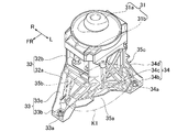
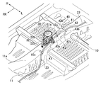
- FIG. 4A is an external perspective view of a single shift selection mechanism according to the first embodiment
- FIG. 4B is an external perspective view of the shift selection mechanism according to the first embodiment in an attached state.
- FR indicates the front of the vehicle
- R indicates the right side of the vehicle
- L indicates the left side of the vehicle.
- the shift selection mechanism 30 includes a shift selection device 31 and a support bracket (device support means) 32 as shown in FIG. 4A.
- the shift selection device 31 has an operation stick 31a and a control circuit 31b as shown in FIG. 4A.
- the shift selection device 31 outputs a signal for switching the driving range position from the control circuit 31b to the automatic transmission by tilting the operation stick 31a. That is, the shift selection device 31 is an operation part having a shift-by-wire structure.
- the support bracket 32 supports the shift selection device 31 in a state where a cable insertion space K1 is left between the shift selection device 31 and the upper surface 11a of the floor tunnel 11.
- the support bracket 32 includes a support leg 32a that stands up from the floor tunnel 11, and a pedestal portion 32b that is supported by the upper end of the support leg 32a and to which the shift selection device 31 is attached.
- the support bracket 32 is made of resin, and is formed separately from the shift selection device 31.
- the support leg 32a is fixed to the front leg portion 33 fixed to the center portion in the vehicle width direction of the upper surface 11a of the floor tunnel 11, and is positioned rearward of the front leg portion 33 and aligned in the vehicle width direction. It has a tripod structure having a pair of rear legs 34, 34 (see FIG. 5A).
- the front leg portion 33 includes a base plate 33b having a bolt through hole 33a formed at the lower end portion, a leg portion 33c that bifurcates in the left-right direction and connects to the pedestal portion 32b as it goes upward from the base plate 33b. have.
- the rear leg 34 includes a base plate 34b having a bolt through hole 34a formed at the lower end, an arm 34c extending from the base plate 34b to the front of the vehicle and connected to the front leg 33, and a base plate 34b.
- a leg portion 34d extending upward and connected to the pedestal portion 32b.
- the pedestal portion 32b is a hollow frame member opened in the vehicle front-rear direction, and the control circuit 31b of the shift selection device 31 is disposed on the inner side, and the operation stick 31a of the shift selection device 31 is attached on the upper side.
- the support bracket 32 surrounds the cable insertion space K1 by the support leg 32a and the pedestal portion 32b.
- the cable insertion space K1 is surrounded by the front leg 33 and the arm part 34c of the one rear leg 34 and is opened toward the left side of the vehicle, the left open part 35a, the front leg 33 and the other.
- a right opening 35b surrounded by the arm 34c of the rear leg 34 and opened toward the left side of the vehicle, and each leg 33c and pedestal 32b of the pair of left and right rear legs 34, 34.
- a rear opening 35c that is surrounded and opened toward the rear of the vehicle.
- the airbag sensor mechanism 40 includes an airbag sensor (sensor device) 41 and a sensor support bracket (sensor support means) 42.
- the airbag sensor 41 is a so-called acceleration sensor, and detects a collision input to the electric vehicle 1.
- an airbag ECU (not shown) deploys the airbag unit.
- the sensor support bracket 42 supports the airbag sensor 41 with the second cable insertion space K2 between the upper surface 11a of the floor tunnel 11.
- the sensor support bracket 42 is supported by a pair of support legs 42a, 42a standing up from the floor tunnel 11, a top part 42b of the pair of support legs 42a, and a base part 42b on which the airbag sensor 41 is placed and fixed. have.
- the pair of support legs 42a and 42a are arranged in the vehicle width direction and surround both sides of the second cable insertion space K2.
- the pedestal portion 42b covers the upper side of the second cable insertion space K2, and the airbag sensor 41 is fixed to the upper surface.
- the sensor support bracket 42 surrounds the second cable insertion space K2 by the pair of support legs 42a and 42a and the base portion 42b.
- the second cable insertion space K2 includes a front opening portion 43a that opens to the front of the vehicle and a rear opening portion 43b that opens to the rear of the vehicle.
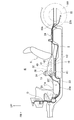
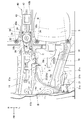
- FIG. 5A is a plan view of a principal part showing the electric vehicle of the first embodiment.
- FIG. 5B is a side view of an essential part showing the electric vehicle of the first embodiment.
- FR indicates the front of the vehicle
- UP indicates the upper side of the vehicle
- R indicates the right side of the vehicle
- L indicates the left side of the vehicle.
- the configuration of the brake cable according to the first embodiment will be described with reference to FIGS. 2B, 3, 5 ⁇ / b> A, and 5 ⁇ / b> B.
- an operation pedal 21 is provided at the vehicle front position of the seat S, and a pair of inner sides of the left and right rear wheels RL and RR located behind the seat S is provided. Brake units 22 and 22 are arranged, respectively.
- the floor panel 10 is formed with a floor tunnel 11 in which a central portion in the vehicle width direction swells upward in the vehicle and extends in the vehicle front-rear direction.
- a shift selection mechanism 30 having a shift selection device 31 and an airbag sensor mechanism 40 having an airbag sensor 41 are sequentially arranged on the upper surface 11a of the floor tunnel 11 from the vehicle front side. At this time, the shift selection mechanism 30 is installed at a side position of the sheet S.
- the brake cable 23 that connects the operation pedal 21 of the parking brake mechanism 20 and the pair of brake units 22 and 22 is connected to the operation pedal 21 at one end, and as shown in FIG. Extends along the dash panel D toward the lower side of the vehicle (part A in FIGS. 3 and 5A).
- a side member 13 extending in the vehicle front-rear direction is set below the position where the operation pedal 21 is attached. Therefore, the brake cable 23 is gradually routed toward the floor tunnel 11 at the center in the vehicle width direction as it goes downward in the vehicle.
- the midway position of the brake cable 23 is fixed to the dash panel D by the first clip 15a.
- the brake cable 23 extended to the lower end portion 11c of the side surface 11b of the floor tunnel 11 serving as a boundary position between the floor tunnel 11 and the floor panel 10 is directed toward the rear of the vehicle along the lower end portion 11c of the floor tunnel 11. It is routed (B section in FIG. 5A). Thereafter, the brake cable 23 is gradually directed upward in the vehicle rearward direction at the front side position of the driver seat S, and scoops up the side surface 11b of the floor tunnel 11 (C portion in FIG. 5A). The intermediate position of the brake cable 23 is fixed to the floor panel 10 near the lower end portion 11c of the floor tunnel 11 by the second clip 15b.
- the electric vehicle 1 is provided with an air conditioner duct 16 for guiding the conditioned air from the air conditioner unit 8 to the lower side of the seat S. It has a flat shape along the side surface 11 b of the floor tunnel 11.
- the brake cable 23 passes through a gap space formed between the flat portion of the air conditioning duct 16 and the side surface 11b of the floor tunnel 11.
- the brake cable 23 climbing up the side surface 11b of the floor tunnel 11 is fixed to the upper surface 11a of the floor tunnel 11 by the third clip 15c, and then routed toward the rear of the vehicle along the upper surface 11a of the floor tunnel 11.
- the shift selection mechanism 30 and the airbag sensor mechanism 40 are provided on the upper surface 11a of the floor tunnel 11, but the brake cable 23 passes through the cable insertion space K1 and the second cable insertion space K2 in order. It is routed (D section in FIG. 5A). That is, as shown in FIG. 5B, the brake cable 23 is routed from the left opening 35a toward the rear opening 35c in the cable insertion space K1. In the second cable insertion space K2, the cable is routed from the front opening 43a toward the rear opening 43b.
- the brake cable 23 that has passed through the second cable insertion space K2 is provided with an equalizer 24.
- the brake cable 23 branches into two rear cables 23b, and then passes through the floor panel 10 to the underfloor space Y. It is pulled out (see FIG. 2B).
- a stepping type operation pedal 21 of the parking brake mechanism 20 is provided in front of the seat S. Therefore, when routing the brake cable 23 from the operation pedal 21 toward the rear of the vehicle, it is necessary to avoid interference with the seat S.
- an air conditioner duct 16 for guiding the conditioned air from the air conditioner unit 8 is installed between the lower surface of the seat S and the floor panel 10. Therefore, the brake cable 23 cannot be routed between the seat S and the floor panel 10. Further, as shown in FIG. 5A, the seat S is close to the side surface 11b of the floor tunnel 11 formed in the center portion of the floor panel 10 in the vehicle width direction. Therefore, the brake cable 23 cannot be routed between the seat S and the side surface 11 b of the floor tunnel 11.
- the side surface of the floor tunnel 11 is positioned in front of the seat S. 11b must be crawled up and routed along the top surface 11a.
- a gap is provided between the seat S and the side surface 11b of the floor tunnel 11 so that the brake cable 23 can be routed, it is not necessary to route the brake cable 23 on the upper surface 11a of the floor tunnel 11.
- the dimension in the vehicle width direction of the electric vehicle 1 increases, which is not preferable from the viewpoint of vehicle compactness.
- the brake cable 23 is preferably routed in a straight line in order to smoothly transmit the traction force by the operation pedal 21 to the brake unit 22. That is, when this brake cable 23 is bent, it is necessary to make the bending R as large as possible. Therefore, it is necessary to route the brake cable 23 so as to climb up the side surface 11b of the floor tunnel 11 at a position as far as possible from the operation pedal 21 and close to the seat S.
- a brake pedal and an accelerator pedal are installed at the vehicle forward position of the seat S. Therefore, when routing the brake cable 23, it is necessary to avoid interference with these pedals.
- a shift selection mechanism 30 is disposed at a lateral position of the seat S, and an airbag sensor mechanism 40 is disposed on the vehicle rear side of the shift selection mechanism 30. . Therefore, when routing the brake cable 23, it is necessary to avoid interference with these mechanisms 30 and 40.
- the brake cable 23 extending from the operation pedal 21 provided in front of the seat S is directed toward the vehicle lower side along the dash panel D, and gradually in the center in the vehicle width direction. It is routed toward the floor tunnel 11. Thereby, interference with the side member 13 and the brake cable 23 set below the attachment position of the operation pedal 21 can be avoided.
- the brake cable 23 is routed toward the rear of the vehicle along the lower end portion 11c of the side surface 11b of the floor tunnel 11, which is the boundary position between the floor tunnel 11 and the floor panel 10. Then, at the front side position of the driver seat S, the vehicle is gradually turned upward as it goes rearward of the vehicle, and the side surface 11b of the floor tunnel 11 is scooped up.
- the lower end portion 11 c of the side surface 11 b of the floor tunnel 11 has a corner shape formed by the floor panel 10 that is a horizontal plane and the floor tunnel 11 that rises from the floor panel 10. That is, the side surface 11b of the floor tunnel 11 is in the way, and it is difficult for the driver's feet to enter the corner-shaped portion formed at the lower end portion 11c of the floor tunnel 11. Therefore, by arranging the brake cable 23 along the lower end portion 11 c of the corner-shaped floor tunnel 11, it is possible to make it difficult for the driver's feet to contact the brake cable 23.
- the shift selection device 31 is supported by the support bracket 32 with a cable insertion space K1 between the upper surface 11a of the floor tunnel 11.
- the airbag sensor 41 is supported by the sensor support bracket 42 with a second cable insertion space K ⁇ b> 2 between the upper surface 11 a of the floor tunnel 11. Therefore, the brake cable 23 that climbs up the side surface 11b of the floor tunnel 11 and reaches the upper surface 11a of the floor tunnel 11 is routed so as to penetrate the cable insertion space K1, and also penetrates the second cable insertion space K2. So that it is routed.
- the brake cable 23 sequentially passes below the shift selection device 31 and below the airbag sensor 41 when the upper surface 11a of the floor tunnel 11 is routed toward the rear of the vehicle.
- the cable insertion space K1 includes a left open portion 35a that opens toward the left side of the vehicle, and a right open portion 35b that opens toward the right side of the vehicle. Therefore, with respect to the floor tunnel 11 formed at the center in the vehicle width direction, the bending R of the brake cable 23 is not reduced regardless of whether the operation pedal 21 of the parking brake mechanism 20 is on the right side or the left side of the vehicle.
- the cable can be smoothly routed in the cable insertion space K1.
- the operation pedal 21 is provided in the vicinity of the left end portion of the dash panel D, and the brake cable 23 is routed from the left side of the floor tunnel 11 toward the floor tunnel 11. And it inserts in the cable penetration space K1 from the left side opening part 35a opened toward the vehicle left side.
- the operation pedal 21 is provided on the right side of the vehicle with respect to the floor tunnel 11.
- the brake cable 23 is routed from the right side of the floor tunnel 11 toward the floor tunnel 11. And it inserts in the cable penetration space K1 from the right side opening part 35b opened toward the vehicle right side. In this way, the brake cable 23 can be smoothly routed regardless of whether the operation pedal 21 is on the right side or the left side of the vehicle with respect to the floor tunnel 11.
- the support bracket 32 has the support leg 32a standing from the floor tunnel 11, and the pedestal portion 32b supported by the support leg 32a. Therefore, even when the shift selection device 31 is stably supported and vibration occurs in the electric vehicle 1, the brake cable 23 is prevented from coming into contact with the shift selection device 31.
- the support leg 32a of the support bracket 32 has a tripod structure having a single front leg 33 and a pair of rear legs 34, 34 arranged in the vehicle width direction, for example, four support legs are provided.
- the installation space of the support bracket 32 can be made more compact than in the case of. As a result, it is possible to make it difficult for the brake cable 23 to contact the support bracket 32.
- a foot-operated operation pedal 21 provided in front of a driver seat (seat) S and a parking brake unit 22 provided on wheels (rear wheels) RL and RR behind the driver seat S.
- a parking brake cable 23 to be connected;
- a shift selection device 31 that is operated by a driver and outputs a signal for switching the driving range position;
- Device support means (support bracket) 32 for supporting the shift selection device 31 at a lateral position of the driver seat S in a state where a cable insertion space K1 is left between the upper surface 11a of the floor tunnel 11;
- the parking brake cable 23 is routed so as to face the upper surface 11a of the floor tunnel 11 on the vehicle front side of the driver seat S and to penetrate the cable insertion space K1. This prevents interference between the parking brake cable 23 arranged on the floor tunnel 11 from the front side of the seat S toward the rear of the vehicle and the shift selection device 31 set at the seat side position on the floor tunnel 11. be able to.
- the cable insertion space is K1, a left opening 35a that opens toward the left side of the vehicle, a right opening 35b that opens toward the right side of the vehicle, and a rear opening 35c that opens toward the rear of the vehicle. It was set as the structure which has. Thereby, even if the operation pedal 21 is set to the left or right direction with respect to the floor tunnel 11, the parking brake cable 23 can be smoothly routed in the cable insertion space K1 without reducing the bending R of the parking brake cable 23. .
- the device support means (support bracket) 32 includes a support leg 32a erected from the upper surface 11a of the floor tunnel 11, and a pedestal portion 32b supported by the support leg 32a and to which the shift selection device 31 is attached. It was set as the structure which has. Thereby, the shift selection device 31 can be stably supported, and the parking brake cable 23 can be prevented from coming into contact with the shift selection device 31 when the vehicle vibrates.
- the support leg 32a includes a single front leg 33, and a pair of rear legs 34, 34 that are arranged at the vehicle rear side of the front leg 33 and are arranged in the vehicle width direction.
- the tripod structure is provided. Thereby, the installation space of the device support means (support bracket) 32 can be made compact.
- the floor tunnel 11 is formed by bulging the floor panel 10 upward of the vehicle,
- the parking brake cable 23 is routed toward the rear of the vehicle along the boundary position (lower end portion) 11c between the floor panel 10 and the floor tunnel 11. Accordingly, it is possible to make it difficult for the driver's feet to contact the parking brake cable 23 when the electric vehicle 1 is driven.
- a sensor device (airbag sensor) 41 mounted on the vehicle is supported at a position behind the shift selection device 31 with a second cable insertion space K2 between the floor tunnel 11 and the vehicle.
- Sensor support means (sensor support bracket) 42 is provided,
- the parking brake cable 23 penetrating the cable insertion space K1 is configured to be routed so as to penetrate the second cable insertion space K2.
- the parking brake cable routing structure of the present invention has been described based on the first embodiment. However, the specific configuration is not limited to this embodiment, and the invention according to each claim of the claims. Design changes and additions are permitted without departing from the gist of the present invention.
- Example 1 although the example which provided the operation pedal 21 of the parking brake mechanism 20 on the vehicle left side with respect to the floor tunnel 11 was shown, it is not restricted to this.
- An operation pedal 21 may be provided on the right side of the vehicle with respect to the floor tunnel 11.
- the support bracket 32 has a tripod structure having a single front leg 33 and a pair of rear legs 34, 34 arranged in the vehicle width direction.
- the present invention is not limited to this, and may have four legs having a pair of front legs, or may have a structure having more legs.
- the support bracket 32 since the support bracket 32 only needs to have an opening portion that opens in the direction in which the operation pedal 21 of the parking brake mechanism 20 is provided, only one of the left opening portion 35a and the right opening portion 35b is required. Or an open portion opened toward the front of the vehicle.
- the device support means may be any device that supports the shift selection device 31 in a state where a cable insertion space is provided between the shift selection device 31 and the upper surface 11 a of the floor tunnel 11.
- the sensor device mounted on the vehicle is the airbag sensor 41 of the airbag sensor mechanism 40, but is not limited thereto.
- an ABS sensor a yaw rate sensor, a lateral gravity sensor, a longitudinal gravity sensor, or the like may be used.
- the parking brake cable routing structure of the first embodiment is applied to the electric vehicle 1, the present invention is not limited to this. It can be applied to engine vehicles, hybrid vehicles, fuel cell vehicles, and the like. In other words, the present invention can be applied to any vehicle including a stepping-type operation pedal, a brake cable routed from the front to the rear of the vehicle, and a shift selection device.
Landscapes
- Engineering & Computer Science (AREA)
- Transportation (AREA)
- Mechanical Engineering (AREA)
- Chemical & Material Sciences (AREA)
- Combustion & Propulsion (AREA)
- Body Structure For Vehicles (AREA)
- Braking Elements And Transmission Devices (AREA)
- Transmission Of Braking Force In Braking Systems (AREA)
Abstract
Description
しかしながら、フロアトンネル上面であってシートの側方位置にシフト選択デバイスを設定する場合では、ドライバーシートの直前位置でフロアトンネルの側壁を這い上がってフロアトンネル上面に至ったブレーキケーブルが、このシフト選択デバイスと干渉するという問題が生じる。
前記ブレーキケーブルは、ドライバーシートの前方に設けられた足踏み式の操作ペダルと、前記ドライバーシートよりも後方の車輪に設けられたパーキングブレーキユニットと、を連結する。
前記シフト選択デバイスは、ドライバーにより操作されて、運転レンジ位置を切り替える信号を出力する。
前記デバイス支持手段は、前記シフト選択デバイスを、フロアトンネルの上面との間にケーブル挿通空間を空けた状態で、前記ドライバーシートの側方位置に支持する。
そして、前記ブレーキケーブルを、前記ドライバーシートよりも車両前方側で前記フロアトンネルの上面に向けると共に、前記ケーブル挿通空間を貫通するように配索する。
そのため、ドライバーシートの前方に設けられた足踏み式の操作ペダルから延在するブレーキケーブルを、ドライバーシートよりも車両前方側でフロアトンネルの上面に向けて配索する際、ドライバーシートの側方位置で支持されたシフト選択デバイスと干渉することはない。
この結果、フロアトンネル上をドライバーシートの前側から車両後方に向けて配索するブレーキケーブルと、フロアトンネル上のシートの側方位置に設定されたシフト選択デバイスとの干渉を防止することができる。
実施例1のパーキングブレーキケーブルの配索構造の構成を、「電気自動車の全体構成」、「電気自動車の搭載構成」、「パーキングブレーキ機構の構成」、「シフト選択機構の構成」、「エアバッグセンサ機構の構成」、「ブレーキケーブルの配索構成」に分けて説明する。
図1は、実施例1のケーブル配索構造が適用された電気自動車の主要構造を示す全体斜視図である。以下、図1に基づき、実施例1の電気自動車の全体構成を説明する。
図2Aは、実施例1の電気自動車を示す概略全体側面図である。図2Bは、実施例1の電気自動車を示す概略全体平面図である。なお、図中FRは車両前方を示し、UPは車両上方を示し、Rは車両右側方を示し、Lは車両左側方を示す。以下、図2A,図2Bに基づき、実施例1の電気自動車の搭載構成を説明する。
また、実施例1のフロアパネル10は、車幅方向中央部を車両上方に向けて膨出することで形成され、車両前後方に延びるフロアトンネル11を有している。
図3は、実施例1の操作ペダルを示す斜視図である。以下、図2A,図2B,図3に基づき、実施例1のパーキングブレーキ機構の構成を説明する。
そして、図2Aに示すように、フロントケーブル23a及びイコライザ24は、フロアパネル10の車室空間Rに面した上面に配索され、リヤケーブル23bの途中位置がフロアパネル10を貫通して床下空間Yに引き出される。
図4Aは、実施例1のシフト選択機構の単体の外観斜視図であり、図4Bは、実施例1のシフト選択機構の取付状態の外観斜視図である。図中FRは車両前方を示し、Rは車両右側方を示し、Lは車両左側方を示す。以下、図4A,図4Bに基づき、実施例1のシフト選択機構の構成を説明する。
前記前側脚部33は、下端部にボルト貫通孔33aが形成されたベースプレート33bと、このベースプレート33bから上方に向かうにつれて、左右方向に二股に分岐すると共に台座部32bに連結した脚部33cと、を有している。
前記後側脚部34は、下端部にボルト貫通孔34aが形成されたベースプレート34bと、このベースプレート34bから車両前方にアーチ状に延びて前側脚部33に連結するアーム部34cと、ベースプレート34bから上方に延びて台座部32bに連結した脚部34dと、を有している。
前記エアバッグセンサ機構40は、図4Bに示すように、エアバッグセンサ(センサ装置)41と、センサ支持ブラケット(センサ支持手段)42と、を有している。
図5Aは、実施例1の電気自動車を示す要部平面図である。図5Bは、実施例1の電気自動車を示す要部側面図である。なお、図中FRは車両前方を示し、UPは車両上方を示し、Rは車両右側方を示し、Lは車両左側方を示す。以下、図2B,図3,図5A,図5Bに基づき、実施例1のブレーキケーブルの配索構成を説明する。
このため、ブレーキケーブル23は、車両下方に向かうにつれて、次第に車幅方向中央部のフロアトンネル11に向かって配索される。なお、ブレーキケーブル23の途中位置が、第1クリップ15aによってダッシュパネルDに固定されている。
その後、ブレーキケーブル23は、ドライバーシートSの前側位置で、車両後方に向かうにつれて次第に車両上方に向けられ、フロアトンネル11の側面11bを這い上がる(図5AにおけるC部)。なお、ブレーキケーブル23の途中位置が、第2クリップ15bによってフロアトンネル11の下端部11c近傍のフロアパネル10に固定されている。
すなわち、このブレーキケーブル23は、図5Bに示すように、ケーブル挿通空間K1では、左側開放部35aから後側開放部35cに向かって配索される。また、第2ケーブル挿通空間K2では、前方開放部43aから後側開放部43bに向かって配索される。
まず、「ブレーキケーブル配索時の課題」を説明し、続いて、実施例1のパーキングブレーキケーブルの配索構造におけるブレーキケーブルの配索作用を説明する。
実施例1では、パーキングブレーキ機構20の足踏み式の操作ペダル21がシートSの前方に設けられている。そのため、この操作ペダル21から車両後方に向けてブレーキケーブル23を配索する際、シートSとの干渉を回避する必要がある。
また、シートSは、図5Aに示すように、フロアパネル10の車幅方向中央部に形成したフロアトンネル11の側面11bに近接している。そのため、シートSとフロアトンネル11の側面11bとの間にブレーキケーブル23を配索することはできない。
なお、シートSとフロアトンネル11の側面11bとの間に、ブレーキケーブル23を配索可能な程度の隙間を設ける場合では、ブレーキケーブル23をフロアトンネル11の上面11aに配索させる必要はなくなる。しかし、この場合では、電気自動車1の車幅方向寸法が増大してしまい、車両コンパクト化の観点から好ましくない。
実施例1のパーキングブレーキ配索構造では、シートSの前方に設けられた操作ペダル21から延在したブレーキケーブル23は、ダッシュパネルDに沿いながら車両下方に向かいつつ、次第に車幅方向中央部のフロアトンネル11に向かって配索される。これにより、操作ペダル21の取付位置の下方に設定されたサイドメンバ13とブレーキケーブル23との干渉が回避できる。
また、フロアトンネル11の側面11bの下端部11cは、水平面であるフロアパネル10と、そのフロアパネル10から立ち上がったフロアトンネル11とで形成されたコーナー形状となっている。つまり、フロアトンネル11の側面11bが邪魔になり、フロアトンネル11の下端部11cに形成されるコーナー形状部分には、ドライバーの足が入り込みにくくなっている。そのため、このコーナー形状のフロアトンネル11の下端部11cに沿ってブレーキケーブル23を配索することで、ドライバーの足がブレーキケーブル23に接触しにくくすることができる。
そのため、フロアトンネル11の側面11bを這い上がり、フロアトンネル11の上面11aに至ったブレーキケーブル23は、ケーブル挿通空間K1を貫通するように配索されると共に、第2ケーブル挿通空間K2を貫通するように配索される。
また、フロアトンネル11上をシートSの前側から車両後方に向けて配索するブレーキケーブル23と、フロアトンネル11上のエアバッグセンサ41との干渉も防止することができる。
一方、ハンドルが車両右側に設定される右ハンドル車では、操作ペダル21はフロアトンネル11よりも車両右側に設けられる。この場合、ブレーキケーブル23は、フロアトンネル11の右側からフロアトンネル11に向かって配索される。そして、車両右側方に向かって開放した右側開放部35bからケーブル挿通空間K1に挿入される。
このように、フロアトンネル11に対して操作ペダル21が車両右側、車両左側のいずれにあっても、ブレーキケーブル23のスムーズな配索が可能となる。
実施例1のパーキングブレーキケーブルの配索構造にあっては、下記に列挙する効果を得ることができる。
ドライバーにより操作されて、運転レンジ位置を切り替える信号を出力するシフト選択デバイス31と、
前記シフト選択デバイス31を、フロアトンネル11の上面11aとの間にケーブル挿通空間K1を空けた状態で、前記ドライバーシートSの側方位置に支持するデバイス支持手段(支持ブラケット)32と、
を備え、
前記パーキングブレーキケーブル23を、前記ドライバーシートSよりも車両前方側で前記フロアトンネル11の上面11aに向けると共に、前記ケーブル挿通空間K1を貫通するように配索する構成とした。
これにより、フロアトンネル11上をシートSの前側から車両後方に向けて配索するパーキングブレーキケーブル23と、フロアトンネル11上のシート側方位置に設定されたシフト選択デバイス31との干渉を防止することができる。
これにより、フロアトンネル11に対して操作ペダル21が左右いずれの方向に設定されても、パーキングブレーキケーブル23の曲げRを小さくすることなく、ケーブル挿通空間K1内にスムーズに配索することができる。
これにより、シフト選択デバイス31を安定的に支持することができ、車両振動時等にパーキングブレーキケーブル23がシフト選択デバイス31に接触することを防止できる。
これにより、デバイス支持手段(支持ブラケット)32の設置スペースのコンパクト化を図ることができる。
前記パーキングブレーキケーブル23を、前記フロアパネル10と前記フロアトンネル11との境界位置(下端部)11cに沿わせながら車両後方に向かって配索する構成とした。
これにより、電気自動車1の運転時に、ドライバーの足がパーキングブレーキケーブル23に接触しにくくすることができる。
前記ケーブル挿通空間K1を貫通した前記パーキングブレーキケーブル23を、前記第2ケーブル挿通空間K2を貫通するように配索する構成とした。
これにより、シフト選択デバイス31の車両後方側に、センサ装置(エアバッグセンサ)41を設けた場合であってもあっても、パーキングブレーキケーブル23を、車幅方向中央部において屈曲を抑えた状態で配索することができる。
Claims (6)
- ドライバーシートの前方に設けられた足踏み式の操作ペダルから車両後方に延在され、
前記ドライバーシートよりも後方の車輪に設けられたパーキングブレーキユニットに連結するパーキングブレーキケーブルと、
ドライバーにより操作されて、運転レンジ位置を切り替える信号を出力するシフト選択デバイスと、
前記シフト選択デバイスを、フロアトンネルの上面との間にケーブル挿通空間を空けた状態で、前記ドライバーシートの側方位置に支持するデバイス支持手段と、
を備え、
前記パーキングブレーキケーブルを、前記ドライバーシートよりも車両前方側で前記フロアトンネルの上面に向けると共に、前記ケーブル挿通空間を貫通するように配索する
ことを特徴とするパーキングブレーキケーブルの配索構造。 - 請求項1に記載されたパーキングブレーキケーブルの配索構造において、
前記ケーブル挿通空間は、車両左側方に向かって開放した左側開放部と、車両右側方に向かって開放した右側開放部と、車両後方に向かって開放した後側開放部と、を有する
ことを特徴とするパーキングブレーキケーブルの配索構造。 - 請求項1又は請求項2に記載されたパーキングブレーキケーブルの配索構造において、
前記デバイス支持手段は、前記フロアトンネルの上面から起立する支持脚と、前記支持脚に支持されると共に前記シフト選択デバイスが取り付けられる台座部と、を有する
ことを特徴とするパーキングブレーキケーブルの配索構造。 - 請求項3に記載されたパーキングブレーキケーブルの配索構造において、
前記支持脚を、単独の前側脚部と、前記前側脚部よりも車両後方位置に配置されると共に、車幅方向に並ぶ一対の後側脚部と、を備える三脚構造とする
ことを特徴とするパーキングブレーキケーブルの配索構造。 - 請求項1から請求項4のいずれか一項に記載されたパーキングブレーキケーブルの配索構造において、
前記フロアトンネルは、フロアパネルを車両上方に向かって膨出することで形成され、
前記パーキングブレーキケーブルを、前記フロアパネルと前記フロアトンネルとの境界位置に沿わせながら車両後方に向かって配索する
ことを特徴とするパーキングブレーキケーブルの配索構造。 - 請求項1から請求項5のいずれか一項に記載されたパーキングブレーキケーブルの配索構造において、
車両に搭載されるセンサ装置を、前記シフト選択デバイスよりも車両後方位置で、前記フロアトンネルとの間に第2ケーブル挿通空間を空けた状態で支持するセンサ支持手段を設け、
前記ケーブル挿通空間を貫通した前記パーキングブレーキケーブルを、前記第2ケーブル挿通空間を貫通するように配索する
ことを特徴とするパーキングブレーキケーブルの配索構造。
Priority Applications (4)
| Application Number | Priority Date | Filing Date | Title |
|---|---|---|---|
| JP2014536737A JP5854151B2 (ja) | 2012-09-18 | 2013-09-03 | パーキングブレーキケーブルの配索構造 |
| CN201380047838.XA CN104619563B (zh) | 2012-09-18 | 2013-09-03 | 停车制动拉索的布线构造 |
| EP13840004.9A EP2899080B1 (en) | 2012-09-18 | 2013-09-03 | Structure for routing parking brake cable |
| US14/417,806 US9505387B2 (en) | 2012-09-18 | 2013-09-03 | Wiring structure of a parking brake cable |
Applications Claiming Priority (2)
| Application Number | Priority Date | Filing Date | Title |
|---|---|---|---|
| JP2012-204195 | 2012-09-18 | ||
| JP2012204195 | 2012-09-18 |
Publications (1)
| Publication Number | Publication Date |
|---|---|
| WO2014045869A1 true WO2014045869A1 (ja) | 2014-03-27 |
Family
ID=50341186
Family Applications (1)
| Application Number | Title | Priority Date | Filing Date |
|---|---|---|---|
| PCT/JP2013/073695 Ceased WO2014045869A1 (ja) | 2012-09-18 | 2013-09-03 | パーキングブレーキケーブルの配索構造 |
Country Status (5)
| Country | Link |
|---|---|
| US (1) | US9505387B2 (ja) |
| EP (1) | EP2899080B1 (ja) |
| JP (1) | JP5854151B2 (ja) |
| CN (1) | CN104619563B (ja) |
| WO (1) | WO2014045869A1 (ja) |
Cited By (1)
| Publication number | Priority date | Publication date | Assignee | Title |
|---|---|---|---|---|
| CN111942481A (zh) * | 2019-05-15 | 2020-11-17 | 马自达汽车株式会社 | 车辆的下部车体构造 |
Families Citing this family (7)
| Publication number | Priority date | Publication date | Assignee | Title |
|---|---|---|---|---|
| US9488296B1 (en) * | 2015-04-29 | 2016-11-08 | Honda Motor Co., Ltd. | Crash protection sleeve for a parking brake wire |
| US10444442B2 (en) * | 2017-11-03 | 2019-10-15 | Senko Advanced Components, Inc. | MPO optical fiber connector |
| JP7077863B2 (ja) * | 2018-08-21 | 2022-05-31 | トヨタ自動車株式会社 | シフトブラケット |
| JP7110974B2 (ja) * | 2018-12-26 | 2022-08-02 | 株式会社オートネットワーク技術研究所 | 給電システム及び自動車 |
| KR102896178B1 (ko) * | 2020-04-09 | 2025-12-04 | 현대자동차 주식회사 | 시프트 바이 와이어 시스템 |
| JP7353241B2 (ja) * | 2020-06-22 | 2023-09-29 | 本田技研工業株式会社 | 車両 |
| CN116034511B (zh) * | 2020-07-03 | 2025-10-31 | 帝人株式会社 | 由一体成型的纤维增强塑料制成的电池托盘 |
Citations (3)
| Publication number | Priority date | Publication date | Assignee | Title |
|---|---|---|---|---|
| JPH0576931U (ja) | 1992-03-27 | 1993-10-19 | 日産車体株式会社 | パーキングブレーキ装置 |
| JP2000168516A (ja) * | 1998-12-11 | 2000-06-20 | Suzuki Motor Corp | パーキングブレーキケーブル配索部構造 |
| JP2002337629A (ja) * | 2001-05-18 | 2002-11-27 | Suzuki Motor Corp | ケーブル配索構造 |
Family Cites Families (25)
| Publication number | Priority date | Publication date | Assignee | Title |
|---|---|---|---|---|
| US2853144A (en) * | 1953-05-27 | 1958-09-23 | American Motors Corp | Floor supported bracket and brake linkage |
| US3177033A (en) * | 1962-09-20 | 1965-04-06 | Gen Motors Corp | Vehicle compartment closure |
| US4412458A (en) * | 1981-02-12 | 1983-11-01 | General Motors Corporation | Vehicle parking brake actuating mechanism |
| US4716781A (en) * | 1982-01-21 | 1988-01-05 | Dussault Jean Paul | Universal emergency brake for vehicle |
| US4454936A (en) * | 1982-04-01 | 1984-06-19 | Wise Stanley S | Emergency and parking brake arrangement in vehicle braking system |
| JPS59227550A (ja) * | 1983-06-08 | 1984-12-20 | Toyota Motor Corp | パーキングブレーキ操作装置 |
| IT8422586U1 (it) * | 1984-07-16 | 1986-01-16 | Alfa Romeo Spa | Mobiletto con comandi e servi per una autovettura. |
| US4790205A (en) * | 1986-12-15 | 1988-12-13 | Ford Motor Company | Cable flexible joint |
| US4864886A (en) * | 1987-05-05 | 1989-09-12 | Itt Corporation | Console integrated pull to release parking brake actuator |
| IT1231869B (it) * | 1989-03-10 | 1992-01-14 | Fiat Auto Spa | Dispositivo di azionamento a cavi flessibili per il comando di un cambio di velocita' |
| US5054333A (en) * | 1990-05-23 | 1991-10-08 | Dura Mechanical Components, Inc. | Movable pedal lever stop |
| US5106143A (en) * | 1990-08-31 | 1992-04-21 | Prince Corporation | Snap-in floor console |
| US5315893A (en) * | 1992-11-17 | 1994-05-31 | Deere & Company | Vehicle brake mechanism |
| DE19621949C2 (de) * | 1996-05-31 | 2000-09-28 | Daimler Chrysler Ag | Bodenstruktur für einen Personenkraftwagen |
| US5970814A (en) * | 1997-12-05 | 1999-10-26 | Prince Corporation | Integrated floor console |
| US6267217B1 (en) * | 1998-11-13 | 2001-07-31 | Meridian Automotive Systems, Inc. | Modular console assembly for vehicles having transmission shifter and parking brake mechanisms pre-assembled thereto and method for mounting the console assembly to a vehicle interior |
| DE19853656B4 (de) * | 1998-11-20 | 2005-12-08 | Fico Cables, S.A., Rubi | Verbindungseinheit |
| US7028574B1 (en) * | 1999-08-12 | 2006-04-18 | Daimlerchrysler Corporation | Sled system for mounting parking brake and shift assemblies |
| FR2895957B1 (fr) * | 2006-01-12 | 2009-06-12 | Peugeot Citroen Automobiles Sa | Dispositif de commande manuelle d'un organe de freinage, notamment d'un frein de stationnement pour vehicule automobile |
| JP4928807B2 (ja) * | 2006-03-10 | 2012-05-09 | 本田技研工業株式会社 | パーキングロックの解除装置 |
| CN201080181Y (zh) * | 2007-07-05 | 2008-07-02 | 比亚迪股份有限公司 | 一种脚踏式驻车制动装置 |
| JP2009012689A (ja) * | 2007-07-06 | 2009-01-22 | Fuji Heavy Ind Ltd | 足踏み式パーキングブレーキ装置 |
| US7874603B2 (en) * | 2009-04-28 | 2011-01-25 | Automotive Components Holdings, Llc | Console retainer with integrated shifter retention |
| CN201784606U (zh) * | 2010-08-30 | 2011-04-06 | 比亚迪股份有限公司 | 一种驻车制动装置的安装结构 |
| JP5880723B2 (ja) * | 2012-09-18 | 2016-03-09 | 日産自動車株式会社 | パーキングブレーキケーブルの配索構造 |
-
2013
- 2013-09-03 CN CN201380047838.XA patent/CN104619563B/zh not_active Expired - Fee Related
- 2013-09-03 US US14/417,806 patent/US9505387B2/en not_active Expired - Fee Related
- 2013-09-03 EP EP13840004.9A patent/EP2899080B1/en not_active Not-in-force
- 2013-09-03 JP JP2014536737A patent/JP5854151B2/ja not_active Expired - Fee Related
- 2013-09-03 WO PCT/JP2013/073695 patent/WO2014045869A1/ja not_active Ceased
Patent Citations (3)
| Publication number | Priority date | Publication date | Assignee | Title |
|---|---|---|---|---|
| JPH0576931U (ja) | 1992-03-27 | 1993-10-19 | 日産車体株式会社 | パーキングブレーキ装置 |
| JP2000168516A (ja) * | 1998-12-11 | 2000-06-20 | Suzuki Motor Corp | パーキングブレーキケーブル配索部構造 |
| JP2002337629A (ja) * | 2001-05-18 | 2002-11-27 | Suzuki Motor Corp | ケーブル配索構造 |
Non-Patent Citations (1)
| Title |
|---|
| See also references of EP2899080A4 * |
Cited By (2)
| Publication number | Priority date | Publication date | Assignee | Title |
|---|---|---|---|---|
| CN111942481A (zh) * | 2019-05-15 | 2020-11-17 | 马自达汽车株式会社 | 车辆的下部车体构造 |
| EP3738865A1 (en) * | 2019-05-15 | 2020-11-18 | Mazda Motor Corporation | Lower vehicle-body structure of a vehicle, vehicle-body structure of a vehicle, and vehicle |
Also Published As
| Publication number | Publication date |
|---|---|
| EP2899080A4 (en) | 2015-10-21 |
| EP2899080B1 (en) | 2017-05-03 |
| EP2899080A1 (en) | 2015-07-29 |
| JPWO2014045869A1 (ja) | 2016-08-18 |
| CN104619563B (zh) | 2017-06-13 |
| US9505387B2 (en) | 2016-11-29 |
| CN104619563A (zh) | 2015-05-13 |
| US20150251642A1 (en) | 2015-09-10 |
| JP5854151B2 (ja) | 2016-02-09 |
Similar Documents
| Publication | Publication Date | Title |
|---|---|---|
| JP5854151B2 (ja) | パーキングブレーキケーブルの配索構造 | |
| US9950641B2 (en) | Straddle-type electric vehicle | |
| US9937780B2 (en) | Front-drive electric vehicle | |
| US20120118653A1 (en) | In-vehicle electronic component disposing construction for electronic component for electric motor for driving vehicle | |
| JPWO2021111810A5 (ja) | ||
| WO2011142304A1 (ja) | 車両用バッテリの冷却装置 | |
| JP2022154930A (ja) | 電動車両 | |
| JP5715708B2 (ja) | 電気自動車の充電口構造 | |
| JP5667964B2 (ja) | 車両のケーブル配設構造及び車両の組立方法 | |
| JP2021062676A (ja) | 自動車 | |
| JP2013014276A (ja) | 電気自動車のバッテリ支持構造 | |
| JP5880716B2 (ja) | 電動車両のパーキングブレーキ装置及びその組立方法 | |
| JP5880723B2 (ja) | パーキングブレーキケーブルの配索構造 | |
| JP5831640B2 (ja) | 電動車両のパーキングブレーキ装置 | |
| JP5492742B2 (ja) | 鞍乗り型電動車両の冷却ダクト配索構造 | |
| JP2013014275A (ja) | 電気自動車のバッテリ支持構造 | |
| JP7447598B2 (ja) | 車体フロア構造 | |
| JP2008222022A (ja) | コックピットモジュール及び乗員室前部構造 | |
| JP2008174031A (ja) | 電動パーキングブレーキ装置 | |
| JP5857877B2 (ja) | 自動車のレバー取付け構造 | |
| JP2021003936A (ja) | 車両のケーブル取付構造 | |
| WO2026069590A1 (ja) | 車両 | |
| JP4470665B2 (ja) | 車両のダッシュパネル構造 | |
| WO2026069591A1 (ja) | 車両 | |
| WO2026069589A1 (ja) | 車両 |
Legal Events
| Date | Code | Title | Description |
|---|---|---|---|
| 121 | Ep: the epo has been informed by wipo that ep was designated in this application |
Ref document number: 13840004 Country of ref document: EP Kind code of ref document: A1 |
|
| ENP | Entry into the national phase |
Ref document number: 2014536737 Country of ref document: JP Kind code of ref document: A |
|
| WWE | Wipo information: entry into national phase |
Ref document number: 14417806 Country of ref document: US |
|
| NENP | Non-entry into the national phase |
Ref country code: DE |
|
| REEP | Request for entry into the european phase |
Ref document number: 2013840004 Country of ref document: EP |
|
| WWE | Wipo information: entry into national phase |
Ref document number: 2013840004 Country of ref document: EP |