WO2014046285A1 - 車両 - Google Patents
車両 Download PDFInfo
- Publication number
- WO2014046285A1 WO2014046285A1 PCT/JP2013/075715 JP2013075715W WO2014046285A1 WO 2014046285 A1 WO2014046285 A1 WO 2014046285A1 JP 2013075715 W JP2013075715 W JP 2013075715W WO 2014046285 A1 WO2014046285 A1 WO 2014046285A1
- Authority
- WO
- WIPO (PCT)
- Prior art keywords
- vehicle
- front wheel
- rotation
- steering
- rotating
- Prior art date
- Legal status (The legal status is an assumption and is not a legal conclusion. Google has not performed a legal analysis and makes no representation as to the accuracy of the status listed.)
- Ceased
Links
Images







Classifications
-
- B—PERFORMING OPERATIONS; TRANSPORTING
- B62—LAND VEHICLES FOR TRAVELLING OTHERWISE THAN ON RAILS
- B62K—CYCLES; CYCLE FRAMES; CYCLE STEERING DEVICES; RIDER-OPERATED TERMINAL CONTROLS SPECIALLY ADAPTED FOR CYCLES; CYCLE AXLE SUSPENSIONS; CYCLE SIDECARS, FORECARS, OR THE LIKE
- B62K5/00—Cycles with handlebars, equipped with three or more main road wheels
- B62K5/08—Cycles with handlebars, equipped with three or more main road wheels with steering devices acting on two or more wheels
-
- B—PERFORMING OPERATIONS; TRANSPORTING
- B60—VEHICLES IN GENERAL
- B60G—VEHICLE SUSPENSION ARRANGEMENTS
- B60G3/00—Resilient suspensions for a single wheel
- B60G3/01—Resilient suspensions for a single wheel the wheel being mounted for sliding movement, e.g. in or on a vertical guide
-
- B—PERFORMING OPERATIONS; TRANSPORTING
- B62—LAND VEHICLES FOR TRAVELLING OTHERWISE THAN ON RAILS
- B62K—CYCLES; CYCLE FRAMES; CYCLE STEERING DEVICES; RIDER-OPERATED TERMINAL CONTROLS SPECIALLY ADAPTED FOR CYCLES; CYCLE AXLE SUSPENSIONS; CYCLE SIDECARS, FORECARS, OR THE LIKE
- B62K21/00—Steering devices
- B62K21/18—Connections between forks and handlebars or handlebar stems
-
- B—PERFORMING OPERATIONS; TRANSPORTING
- B62—LAND VEHICLES FOR TRAVELLING OTHERWISE THAN ON RAILS
- B62K—CYCLES; CYCLE FRAMES; CYCLE STEERING DEVICES; RIDER-OPERATED TERMINAL CONTROLS SPECIALLY ADAPTED FOR CYCLES; CYCLE AXLE SUSPENSIONS; CYCLE SIDECARS, FORECARS, OR THE LIKE
- B62K5/00—Cycles with handlebars, equipped with three or more main road wheels
- B62K5/02—Tricycles
- B62K5/027—Motorcycles with three wheels
-
- B—PERFORMING OPERATIONS; TRANSPORTING
- B62—LAND VEHICLES FOR TRAVELLING OTHERWISE THAN ON RAILS
- B62K—CYCLES; CYCLE FRAMES; CYCLE STEERING DEVICES; RIDER-OPERATED TERMINAL CONTROLS SPECIALLY ADAPTED FOR CYCLES; CYCLE AXLE SUSPENSIONS; CYCLE SIDECARS, FORECARS, OR THE LIKE
- B62K5/00—Cycles with handlebars, equipped with three or more main road wheels
- B62K5/02—Tricycles
- B62K5/05—Tricycles characterised by a single rear wheel
-
- B—PERFORMING OPERATIONS; TRANSPORTING
- B62—LAND VEHICLES FOR TRAVELLING OTHERWISE THAN ON RAILS
- B62K—CYCLES; CYCLE FRAMES; CYCLE STEERING DEVICES; RIDER-OPERATED TERMINAL CONTROLS SPECIALLY ADAPTED FOR CYCLES; CYCLE AXLE SUSPENSIONS; CYCLE SIDECARS, FORECARS, OR THE LIKE
- B62K5/00—Cycles with handlebars, equipped with three or more main road wheels
- B62K5/10—Cycles with handlebars, equipped with three or more main road wheels with means for inwardly inclining the vehicle body on bends
-
- B—PERFORMING OPERATIONS; TRANSPORTING
- B60—VEHICLES IN GENERAL
- B60G—VEHICLE SUSPENSION ARRANGEMENTS
- B60G2200/00—Indexing codes relating to suspension types
- B60G2200/40—Indexing codes relating to the wheels in the suspensions
- B60G2200/44—Indexing codes relating to the wheels in the suspensions steerable
-
- B—PERFORMING OPERATIONS; TRANSPORTING
- B60—VEHICLES IN GENERAL
- B60G—VEHICLE SUSPENSION ARRANGEMENTS
- B60G2204/00—Indexing codes related to suspensions per se or to auxiliary parts
- B60G2204/40—Auxiliary suspension parts; Adjustment of suspensions
- B60G2204/422—Links for mounting suspension elements
-
- B—PERFORMING OPERATIONS; TRANSPORTING
- B60—VEHICLES IN GENERAL
- B60G—VEHICLE SUSPENSION ARRANGEMENTS
- B60G2204/00—Indexing codes related to suspensions per se or to auxiliary parts
- B60G2204/80—Interactive suspensions; arrangement affecting more than one suspension unit
- B60G2204/83—Type of interconnection
- B60G2204/8302—Mechanical
-
- B—PERFORMING OPERATIONS; TRANSPORTING
- B60—VEHICLES IN GENERAL
- B60G—VEHICLE SUSPENSION ARRANGEMENTS
- B60G2300/00—Indexing codes relating to the type of vehicle
- B60G2300/12—Cycles; Motorcycles
- B60G2300/122—Trikes
-
- B—PERFORMING OPERATIONS; TRANSPORTING
- B60—VEHICLES IN GENERAL
- B60G—VEHICLE SUSPENSION ARRANGEMENTS
- B60G2300/00—Indexing codes relating to the type of vehicle
- B60G2300/45—Rolling frame vehicles
-
- B—PERFORMING OPERATIONS; TRANSPORTING
- B62—LAND VEHICLES FOR TRAVELLING OTHERWISE THAN ON RAILS
- B62K—CYCLES; CYCLE FRAMES; CYCLE STEERING DEVICES; RIDER-OPERATED TERMINAL CONTROLS SPECIALLY ADAPTED FOR CYCLES; CYCLE AXLE SUSPENSIONS; CYCLE SIDECARS, FORECARS, OR THE LIKE
- B62K5/00—Cycles with handlebars, equipped with three or more main road wheels
- B62K2005/001—Suspension details for cycles with three or more main road wheels
Definitions
- the present invention relates to a vehicle including a leanable body frame and two front wheels.
- a vehicle that includes a leanable vehicle body frame, two front wheels, and a steering mechanism for transmitting a steering force input to rotate a steering shaft to a first front wheel and a second front wheel. (See Patent Document 1).
- the rotation operation for transmitting the steering force to the two front wheels and the rotation operation for moving the two front wheels up and down are realized by a joint member that can rotate in two axial directions.
- a joint member that can rotate in two axial directions.
- the space for arranging the rotary shaft members and the movable range of the components connected to the rotary members are likely to be large.
- An object of the present invention is to provide a vehicle capable of suppressing an expansion of a movable range of a member that transmits a steering force while ensuring a large steering angle.
- the vehicle of the present invention capable of solving the above-described problems is A body frame having a head pipe; A steering member having a rotating shaft supported by the head pipe and rotatably supported with respect to the vehicle body frame; A first front wheel disposed to the left of the vehicle width direction center of the vehicle; A second front wheel arranged to the right of the vehicle width direction center of the vehicle; A first support device that is arranged to the left of the center in the vehicle width direction of the vehicle and supports the first front wheel rotatably with the rotation of the steering member; A second support device that is disposed to the right of the vehicle width direction center of the vehicle and supports the second front wheel rotatably with the rotation of the steering member; A steering force transmission mechanism for transmitting a steering force input to the steering member to the first front wheel and the second front wheel; With The steering force transmission mechanism is A central transmission portion provided on the steering member so as not to rotate relative to the steering member; A first rotating part supported by the central transmission part and rotatable with respect to the central transmission part around a first vertical rotation axis
- the first support portion, the second support portion, and the third support portion are left and right as viewed from the front of the vehicle while maintaining the posture in which the respective front and rear rotation shafts face the front and rear direction. Move in the direction. Therefore, in a steering force transmission mechanism that includes a rotating shaft member having a rotating shaft extending in the front-rear direction and a rotating shaft member having a rotating shaft extending in the up-down direction, the support portion on which the tie rod is supported has the rotating shaft in the front-rear direction.
- the case where the vehicle is viewed from above when the vehicle is viewed from above is more suitable when the vehicle is supported rotatably at the center.
- the movable range of the tie rod can be reduced.
- the rotation shaft member having the rotation shaft in the front-rear direction and the rotation shaft member having the rotation shaft in the vertical direction are separately provided, while ensuring a large steering angle.
- the expansion of the movable range of the tie rod during steering can be suppressed.
- the first support portion is connected to the front portion of the first rotation portion
- the second support portion is connected to the front portion of the second rotation portion
- the front portion of the third rotation portion
- the third support part may be connected to.
- the tie rod is a plate-like member extending in the left-right direction, and the length in the vertical direction may be larger than the length in the front-rear direction. According to this configuration, the amount of movement of the tie rod in the front-rear direction during steering can be reduced while securing the rigidity of the tie rod, and the movable range of the tie rod can be reduced.
- the vehicle of the present invention includes a rotating member that is rotatably supported with respect to the vehicle body frame about a rotating shaft disposed above the first front wheel and the second front wheel and that extends in the left-right direction.
- a link mechanism for inclining the first front wheel and the second front wheel by performing an inclination operation in conjunction with the rotation operation of the member may be provided.
- the rotation shaft of the rotating member constituting the link mechanism is disposed above the first front wheel and the second front wheel, the distance between the first front wheel and the second front wheel for disposing the link mechanism. An increase in (tread) can be suppressed.
- the distance between the second vertical rotation shaft and the third vertical rotation shaft in the left-right direction is such that the vertical rotation shaft of the first support device and the second support device in the left-right direction are It may be larger than the distance between the vertical axis of rotation.
- the first front wheel and the second front wheel can be in a posture in which the Ackermann geometry is easily established. For this reason, even when steered greatly, the turning radius of the first front wheel and the second front wheel can be made closer. As a result, the first front wheel and the second front wheel can be smoothly rotated about each wheel axis. Therefore, the riding comfort of the vehicle can be improved.
- the present invention it is possible to provide a vehicle capable of suppressing the expansion of the movable range of a member that transmits a steering force while ensuring a large steering angle.
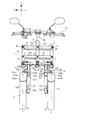
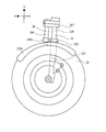
- FIG. 1 is an overall side view of a vehicle according to the present invention. It is the whole vehicle front view in the state where the body cover was removed. It is a partial schematic side view of a 2nd front wheel and a 2nd rotation prevention mechanism. It is a partial side view of a vehicle. It is a whole front view which shows the state which inclined the vehicle. It is a front partial enlarged view showing an operating force transmission mechanism. It is a schematic block diagram which shows a part of operating force transmission mechanism. It is a front partial enlarged view which shows a 2nd bracket and a front wheel. It is a partial side view which shows the periphery of a suppression mechanism. It is a fragmentary perspective view which shows a part of suppression mechanism.
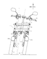
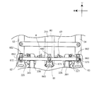
- FIG. 1 It is a whole side view of the vehicle which concerns on the 2nd Embodiment of this invention. It is a front view of the front part of the vehicle of FIG. It is a top view of the front part of the vehicle of FIG. It is a perspective view which shows the structure of the steering force transmission mechanism part of the vehicle of FIG. It is sectional drawing which shows the structure of the steering force transmission mechanism part of the vehicle of FIG. It is a top view of the vehicle front part of the state which steered the vehicle of FIG. It is a front view of the vehicle front part of the state which inclined the vehicle of FIG. It is a front view of the vehicle front part of the state which steered and inclined the vehicle of FIG. FIGS.
- FIGS. 11A and 11B are diagrams for explaining the movement of the steering force transmission mechanism, the first front wheel, and the second front wheel of the vehicle in FIG. 11, in which FIG. 11A is a schematic diagram when straight traveling, and FIG. It is a schematic diagram explaining the movement of the steering force transmission mechanism part of the vehicle of FIG. It is a schematic diagram which shows the structure and motion of a uniaxial structure steering force transmission mechanism.
- FIGS. a three-wheeled vehicle 1 which is a kind of vehicle according to an embodiment of the present invention will be described with reference to FIGS.
- the same or corresponding parts are denoted by the same reference numerals, and description of the members will not be repeated.
- the arrow F in the figure indicates the forward direction of the three-wheeled vehicle 1.
- An arrow R in the figure indicates the right direction of the three-wheeled vehicle 1.
- An arrow L in the figure indicates the left direction of the three-wheeled vehicle 1.
- Arrow U indicates the upward direction.
- the outward in the vehicle width direction means a direction from the center in the vehicle width direction to the outside.
- the outward in the vehicle width direction means a direction from the center in the vehicle width direction to the left or right.
- the axis extending in the front-rear direction is an axis inclined at a range of ⁇ 45 ° with respect to the front-rear direction.
- the axis extending in the vertical direction is an axis inclined at a range of ⁇ 45 ° with respect to the vertical direction.
- the axis extending in the left-right direction is an axis inclined at a range of ⁇ 45 ° with respect to the left-right direction.
- the configuration referred to with “first” arranged on the right side of the vehicle is the configuration referred to with “second” arranged on the right side of the vehicle in the claims and the second embodiment.
- the configuration referred to with “second” arranged on the left side of the vehicle is referred to with “first” arranged on the left side of the vehicle in the claims and the second embodiment. It corresponds to.
- FIG. 1 is an overall side view of a three-wheeled vehicle 1.
- the front, rear, left, and right directions indicate the front, rear, left, and right directions viewed from the occupant driving the three-wheeled vehicle 1.
- the three-wheel vehicle 1 includes a vehicle body 2, a front wheel 3 and a rear wheel 4.
- the vehicle body 2 is mainly composed of a vehicle body frame 21, a vehicle body cover 22, a handle 23, a seat 24, and a power unit 25.
- the body frame 21 supports the power unit 25, the seat 24, and the like.
- the power unit 25 includes an engine, a mission device, and the like.
- the body frame 21 is indicated by a broken line.
- the vehicle body frame 21 includes a head pipe 211, a down frame 212, and a rear frame 213.
- the head pipe 211 is disposed at the front portion of the vehicle.
- a link mechanism 5 is disposed around the head pipe 211.
- a steering shaft 60 is rotatably inserted into the head pipe 211.
- the steering shaft 60 extends in the vertical direction.
- a handle 23 is attached to the upper end of the steering shaft 60.
- the down frame 212 is inclined downward from the front end toward the rear.
- the rear frame 213 supports the seat 24, the tail lamp, and the like.
- a switch 23 a is attached to the handle 23.
- the body frame 21 is covered with a body cover 22.
- the vehicle body cover 22 includes a front cover 221, a front fender 223, and a rear fender 224.
- the front cover 221 is located in front of the seat 24.
- the front cover 221 covers the head pipe 211 and the link mechanism 5.
- the front fenders 223 are respectively disposed above the pair of left and right front wheels 3.
- the front fender 223 is disposed below the front cover 221.
- the rear fender 224 is disposed above the rear wheel 4.
- the front wheel 3 is located below the head pipe 211 and the link mechanism 5.
- the front wheel 3 is disposed below the front cover 221.
- the rear wheel 4 is disposed below the vehicle body cover 22.
- FIG. 2 is an overall front view showing the three-wheeled vehicle 1 with the vehicle body cover 22 removed.
- the down frame 212 and the like are omitted.
- the three-wheel vehicle 1 includes a handle 23, a steering shaft 60, a head pipe 211, a pair of left and right front wheels 3, a first shock absorber 33, a first rotation prevention mechanism 34, a second shock absorber 35, a second rotation prevention mechanism 36, and a link.
- a mechanism 5, an operation force transmission mechanism 6, and a deformation suppression mechanism 75 are provided.
- the front wheel 3 includes a first front wheel 31 and a second front wheel 32.
- the first front wheel 31 is disposed on the right side with respect to the center in the vehicle width direction.
- a first front fender 223 a is disposed above the first front wheel 31.
- the second front wheel 32 is disposed on the left side with respect to the center in the vehicle width direction.
- a second front fender 223b is disposed above the second front wheel 32.
- the second front wheel 32 is arranged symmetrically with the first front wheel 31 with respect to the center in the vehicle width direction.
- the first support device supports the first front wheel 31.
- the first support device has a first bracket 335.
- the first support device includes a first bracket 335, a first shock absorber 33, and a first rotation prevention mechanism 34.
- the first support device can rotate around the first central axis X by a steering force transmission mechanism.
- the first front wheel 31 is supported by the first support member 331.
- the first front wheel 31 is connected to the lower part of the first support member 331.
- the first support member 331 includes a first outer cylinder 332 and a first guide 333.
- the first outer cylinder 332 has a first support shaft 334 at the lower end.
- the first support shaft 334 supports the first front wheel 31.
- the first outer cylinder 332 extends in the vertical direction.
- a first guide 333 is disposed at the upper end of the first outer cylinder 332.
- the first guide 333 is fixed to the upper part of the first outer cylinder 332.
- the first guide 333 includes a first plate 333a.
- the first plate 333a extends to above the first front fender 223a.
- the first front wheel 31 is rotatable about the first central axis X.
- the first front wheel 31 can rotate around the first central axis X and change its direction.
- the first central axis X intersects the first plate 333a and the first connection point 333c.
- FIG. 3 is a schematic left side view of the second front wheel 32, the second shock absorber 35, and the second rotation prevention mechanism 36.
- the second support device supports the second front wheel 32.
- the second support device has a second bracket 327.
- the second support device includes a second bracket 327, a second shock absorber 35, and a second rotation prevention mechanism 36.
- the second support device can rotate around the second central axis Y by a steering force transmission mechanism.
- the second shock absorber 35 includes a second outer cylinder 322 and a second inner cylinder 326. A part of the second inner cylinder 326 is inserted into the inner periphery of the second outer cylinder 322.
- the second inner cylinder 326 is disposed above the second outer cylinder 322.
- the second inner cylinder 326 is movable relative to the second outer cylinder 322 in the direction in which the second outer cylinder 322 extends.
- a second bracket 327 is disposed at the upper end of the second inner cylinder 326.
- the upper end of the second inner cylinder 326 is fixed to the second bracket 327.
- the second shock absorber 35 is a so-called tele
- the second rotation prevention mechanism 36 prevents the rotation of the second outer cylinder 322 relative to the second inner cylinder 326.
- the second rotation prevention mechanism 36 includes a second guide 325, a second rotation prevention rod 361, and a second bracket 327.
- the second guide 325 guides the moving direction of the second rotation prevention rod 361.
- the second guide 325 includes a second guide cylinder 325b.
- a second rotation preventing rod 361 is inserted in the inner periphery of the second guide cylinder 325b.
- the second rotation preventing rod 361 can move relative to the second guide cylinder 325b.
- the second rotation prevention rod 361 prevents the second front wheel 32 from rotating relative to the second inner cylinder 326.
- the second rotation preventing rod 361 is disposed in parallel with the second shock absorber 35.
- the upper end of the second rotation prevention rod 361 is fixed to the second bracket 327.
- the second rotation prevention rod 361 cannot move relative to the second inner cylinder 326.
- the second bracket 327 fixes the second
- the first shock absorber 33 includes a first outer cylinder 332 and a first inner cylinder 336.
- the first shock absorber 33 has the same configuration as the second shock absorber 35.
- a part of the first inner cylinder 336 is inserted into the inner periphery of the first outer cylinder 332.
- the first inner cylinder 336 is disposed above the first outer cylinder 332.
- the first inner cylinder 336 is movable relative to the first outer cylinder 332 in the direction in which the first outer cylinder 332 extends.
- a first bracket 335 is disposed at the upper end of the first inner cylinder 336.
- the upper end of the first inner cylinder 336 is fixed to the first bracket 335.
- the first shock absorber 33 is a so-called telescopic shock absorber.
- the first rotation prevention mechanism 34 prevents the first outer cylinder 332 from rotating with respect to the first inner cylinder 336.
- the first rotation prevention mechanism 34 has the same configuration as the second rotation prevention mechanism 36.
- the first rotation prevention mechanism 34 includes a first guide 333, a first rotation prevention rod 341, and a first bracket 335.
- the first guide 333 guides the moving direction of the first rotation prevention rod 341.
- the first guide 333 includes a first guide cylinder 333b.
- a first rotation preventing rod 341 is inserted in the inner periphery of the first guide cylinder 333b.
- the first rotation prevention rod 341 can be moved relative to the first guide cylinder 333b.
- the first rotation prevention rod 341 prevents the first front wheel 31 from rotating relative to the first inner cylinder 336.
- the first rotation preventing rod 341 is disposed in parallel with the first shock absorber 33.
- the upper end of the first rotation prevention rod 341 is fixed to the first bracket 335.
- the first rotation prevention rod 341 cannot move relative to the first inner cylinder 336.
- the first bracket 335 fixes the first inner cylinder 336 and the first rotation prevention rod 341.
- the second front wheel 32 is supported by the second support member 321.
- the second front wheel 32 is connected to the lower part of the second support member 321.
- the second support member 321 includes a second outer cylinder 322 and a second guide 325.
- the second outer cylinder 322 has a second support shaft 323 at the lower end.
- the second support shaft 323 supports the second front wheel 32.
- the second outer cylinder 322 extends in the vertical direction.
- a second guide 325 is disposed at the upper end of the second outer cylinder 322.
- the second guide 325 is fixed to the upper part of the second outer cylinder 322.
- the second guide 325 includes a second plate 325a.
- the second plate 325a extends to above the second front fender 223b.
- the second front wheel 32 rotates about the second central axis Y.
- the second front wheel 32 can rotate around the second central axis Y and change its direction.
- the second central axis Y intersects the second plate 325a and
- the link mechanism 5 is disposed below the handle 23.
- the link mechanism 5 is disposed above the first front wheel 31 and the second front wheel 32.
- the link mechanism 5 is connected to the head pipe 211.
- the link mechanism 5 includes a first cross member 51, a second cross member 52, a first side member 53, and a second side member 54.
- the first cross member 51 is supported by the body frame 21 (head pipe 211) by the support portion A.
- the first cross member 51 is supported by the vehicle body frame 21 so as to be rotatable about the rotation axis (support portion A).
- the first cross member 51 is supported by the head pipe 211 so as to be rotatable within a plane including the first cross member 51 and the second cross member 52.
- the first cross member 51 is rotatable relative to the steering shaft 60 in the left-right direction. Even when the steering shaft 60 rotates with the rotation of the handle 23, the first cross member 51 does not rotate with respect to the steering shaft 60.
- the first cross member 51 includes a pair of plate-like members 512.
- the first cross member 51 extends in the vehicle width direction.
- the pair of plate-like members 512 sandwich the head pipe 211 in the front-rear direction.
- the right end of the first cross member 51 is connected to the first side member 53 by the connection portion B.
- the first cross member 51 is connected to the first side member 53 so as to be rotatable about the rotation axis B.
- the left end of the first cross member 51 is connected to the second side member 54 by the connecting portion C.
- the first cross member 51 is attached to the second side member 52 so as to be rotatable relative to the rotation axis C.
- the first cross member 51 is rotatable with respect to the first side member 53 and the second side member 54 in a plane including the first cross member 51 and the second cross member 52.
- the second cross member 52 is supported by the body frame 21 (head pipe 211) by the support portion D.
- the second cross member 52 is supported by the vehicle body frame 21 so as to be rotatable about the rotation axis (support portion D).
- the second cross member 52 is supported by the head pipe 211 so as to be rotatable within a plane including the first cross member 51 and the second cross member 52.
- the second cross member 52 is disposed below the first cross member 51.
- the second cross member 52 is parallel to the first cross member 51.
- the second cross member 52 has the same length as the first cross member 51.
- the second cross member 52 is rotatable relative to the steering shaft 60 in the left-right direction. Even when the steering shaft 60 rotates with the rotation of the handle 23, the second cross member 52 does not rotate with respect to the steering shaft 60.
- the second cross member 52 includes a pair of plate-like members 522.
- the second cross member 52 extends in the vehicle width direction.
- the pair of plate-like members 522 sandwich the head pipe 211 in the front-rear direction.
- the right end of the second cross member 52 is connected to the first side member 53 by the connection portion E.
- the second cross member 52 is connected to the first side member 53 so as to be rotatable about the rotation axis (connection portion E).
- the left end of the second cross member 52 is connected to the second side member 54 by the connecting portion F.
- the second cross member 52 is connected to the second side member 54 so as to be rotatable about the rotation axis (connection portion F).
- the second cross member 52 is rotatable with respect to the first side member 53 and the second side member 54 in a plane including the first cross member 51 and the second cross member 52.
- the first cross member 51 and the second cross member 52 are a pair of front and rear plate-like members extending in the left-right direction, but the first cross member 51 and the second cross member 52 are the head pipe 211, respectively.
- a member including a member extending rightward from the head and a member extending leftward from the head pipe 211 may be used.
- the first side member 53 is disposed on the right side of the head pipe 211.
- the first side member 53 extends in the direction in which the head pipe 211 extends.
- the first side member 53 extends in the direction in which the steering shaft 60 extends.
- the first side member 53 is disposed above the first front wheel 31.
- the first side member 53 is connected to the first bracket 335 at the lower end.
- the first side member 53 is attached to the first bracket 335 so as to be rotatable about the first central axis X.
- the first bracket 335 rotates around the connection portion with the first side member 53 by rotating the handle 23.
- the first side member 53 does not rotate with respect to the vehicle body frame 21 when the first bracket 335 rotates.
- the first side member 53 is disposed on the right side of the first shock absorber 33.
- the first side member 53 is disposed above the first shock absorber 33.
- the second side member 54 is disposed on the left side of the head pipe 211.
- the second side member 54 extends in the direction in which the head pipe 211 extends.
- the second side member 54 extends in the direction in which the steering shaft 60 extends.
- the second side member 54 is disposed above the second front wheel 32.
- the second side member 54 is connected to the second bracket 327 at the lower end.
- the second side member 54 is attached to the second bracket 327 so as to be rotatable about the second central axis Y.
- the second bracket 327 rotates around the connection portion with the second side member 54 by rotating the handle 23.
- the second side member 54 does not rotate with respect to the vehicle body frame 21 when the second bracket 327 rotates.
- the second side member 54 is disposed on the left side of the second shock absorber 35.
- the second side member 54 is disposed above the second shock absorber 35.
- the operating force transmission mechanism 6 transmits the operating force of the handle 23 to the first front wheel 31 and the second front wheel 32 in accordance with the steering operation by the occupant. A part of the operating force transmission mechanism 6 is disposed below the second cross member 52. The operating force transmission mechanism 6 is disposed above the first front wheel 31 and the second front wheel 32.
- the deformation suppression mechanism 75 suppresses the deformation of the link mechanism 5.
- the deformation suppression mechanism 75 includes the first connection member 11, the second connection member 12, and the suppression mechanism 7.
- the first connecting member 11 is attached to the first plate 333a.
- the first connection member 11 is attached to a first connection point 333 c where the first plate 333 a intersects the first central axis X.
- the 1st connection member 11 does not need to be arrange
- the first connection member 11 is attached to the upper surface of the first plate 333a.
- the first connection member 11 extends from the first plate 333 a toward the head pipe 211.
- the first connecting member 11 includes a rod-shaped portion.
- the first connecting member 11 is disposed below the link mechanism 5.
- the second connecting member 12 is attached to the second plate 325a.
- the second connection member 12 is attached to a second connection point 325c where the second plate 325a intersects the second central axis Y.
- the 2nd connection member 12 does not need to be arrange
- the second connection member 12 is attached to the upper surface of the second plate 325a.
- the second connecting member 12 extends from the second plate 325a toward the head pipe 211.
- the second connection member 12 includes a rod-shaped portion.
- the second connection member 12 is disposed below the link mechanism 5.
- the suppression mechanism 7 suppresses the movement of the first connecting member 11 with respect to the head pipe 211.
- the suppression mechanism 7 suppresses the movement of the second connecting member 12 relative to the head pipe 211.
- the suppression mechanism 7 is disposed below the link mechanism 5.
- FIG. 4 is a left side view around the link mechanism 5 and the second front wheel 32.
- the down frame 212, the handle 23, and the like located behind the link mechanism 5 are omitted.
- the upper portion of the head pipe 211 is sandwiched between a pair of plate-like members 512.
- the lower portion of the head pipe 211 is sandwiched between a pair of plate-like members 522.
- the rotation axis (support portion A) extends so as to intersect with the steering shaft 60.
- the rotation axis (support portion D) extends so as to intersect with the steering shaft 60.
- the upper end of the second shock absorber 35 is disposed below the lower end of the link mechanism 5.
- the upper end of the first shock absorber 33 is disposed below the lower end of the link mechanism 5 in a side view.
- FIG. 5 is an overall front view of the three-wheeled vehicle 1 tilted leftward by an angle T.
- the link mechanism 5 is deformed.
- the head pipe 211 tilts to the left with respect to the vertical.
- the first cross member 51 and the second cross member 52 rotate with respect to the head pipe 211.
- the left end of the first cross member 51 moves to the left from the left end of the second cross member 52.
- the second side member 54 is inclined.
- the second side member 54 is parallel to the head pipe 211. Similar to the second side member 54, the first side member 53 is inclined with respect to the vertical direction. The first side member 53 is parallel to the head pipe 211. When the first side member 53 and the second side member 54 are inclined, the first side member 53 rotates with respect to the first cross member 51 and the second cross member 52. When the first side member 53 and the second side member 54 are inclined, the second side member 54 rotates with respect to the first cross member 51 and the second cross member 52.
- the first front wheel 31 and the second front wheel 32 are tilted with respect to the vertical direction when the vehicle is viewed from the front.
- the first front wheel 31 and the second front wheel 32 maintain a posture parallel to the head pipe 211.
- FIG. 6 is a partially enlarged front view showing the operating force transmission mechanism 6.
- the operating force transmission mechanism 6 includes a steering shaft 60, a first transmission plate 61 (an example of a central transmission unit), a second transmission plate 62 (an example of a right transmission unit), a third transmission plate 63 (an example of a left transmission unit), A first transmission member 67 (an example of a tie rod), a first bracket 335, and a second bracket 327 are included.
- the first transmission plate 61 is connected to the steering shaft 60.
- the first transmission plate 61 is not rotatable relative to the steering shaft 60.
- the steering shaft 60 rotates with respect to the head pipe 211.
- the first transmission plate 61 rotates.
- the second transmission plate 62 is connected to the first side member 53.
- the second transmission plate 62 is rotatably connected to the first side member 53.
- the second transmission plate 62 is fixed to the first bracket 335.
- the second transmission plate 62 is located below the first bracket 335.
- the third transmission plate 63 is connected to the second side member 54.
- the third transmission plate 63 is rotatably connected to the second side member 54.
- the third transmission plate 63 is disposed symmetrically with the second transmission plate 62 with the first transmission plate 61 as the center in the front view.
- the third transmission plate 63 is fixed to the second bracket 327.
- the third transmission plate 63 is located below the second bracket 327.
- the first transmission member 67 transmits the operating force transmitted from the steering shaft 60 to the first bracket 335 and the second bracket 327.
- the first transmission member 67 extends in the vehicle width direction. A detailed configuration for transmitting the operating force from the steering shaft 60 to the first bracket 335 and the second bracket 327 will be described later.
- FIG. 7 is a schematic plan view showing the configuration of the operating force transmission mechanism 6.
- the operating force transmission mechanism 6 is viewed from above, and the structures of the link mechanism 5 and the bracket are all omitted.
- a two-dot chain line indicates a state in which the steering shaft 60 is rotated in the direction of arrow A.
- the operating force transmission mechanism 6 includes a first transmission plate 61, a second transmission plate 62, a third transmission plate 63, a first joint 64, a second joint 65, a third joint 66, and a first transmission member 67.
- the front part of the first transmission plate 61 is narrower than the rear part of the first transmission plate 61.
- a first joint 64 is disposed at the front portion of the first transmission plate 61.
- the width of the front part of the second transmission plate 62 is narrower than the width of the rear part of the second transmission plate 62.
- a second joint 65 is disposed at the front portion of the second transmission plate 62.
- the second transmission plate 62 is disposed on the right side of the first transmission plate 61.
- the width of the front part of the third transmission plate 63 is narrower than the width of the rear part of the third transmission plate 63.
- a third joint 66 is disposed at the front portion of the third transmission plate 63.
- the third transmission plate 63 is disposed on the left side of the first transmission plate 61.
- the first joint 64 includes a first bearing 641 (an example of a first rotating portion), a first shaft 642 (an example of a first vertical rotating shaft), and a first front rod 643 (an example of a first support portion). .
- the first shaft 642 is rotatable relative to the first bearing 641.
- the first bearing 641 supports the first shaft 642.
- the first bearing 641 is supported by the first transmission plate 61.
- the first transmission plate 61 includes a first support hole 641 b that supports the first shaft 641.
- the first shaft 642 is inserted through the first support hole 641b.
- the first bearing 641 is fixed to the first shaft 642.
- the first shaft 642 is disposed at the front end of the first transmission plate 61.
- the first front rod 643 extends forward from the first bearing 641.
- the first front rod 643 is relatively rotatable in the left-right direction around the first shaft 642 as the first bearing 641 rotates with respect to the first transmission plate 61.
- the first front rod 643 is fixed to the first bearing 641.
- the second joint 65 includes a second bearing 651 (an example of a third rotating portion), a second shaft 652 (an example of a third vertical rotating shaft), and a second front rod 653 (an example of a third support portion).
- the second bearing 651 has the same configuration as the first bearing 641.
- the second shaft 652 has the same configuration as the first shaft 642.
- the second front rod 653 has the same configuration as the first front rod 643.
- the third joint 66 includes a third bearing 661 (an example of a second rotating portion), a third shaft 662 (an example of a second vertical rotating shaft), and a third front rod 663 (an example of a second support portion).
- the third bearing 661 has the same configuration as the first bearing 641.
- the third shaft 662 has the same configuration as the first shaft 642.
- the third front rod 663 has the same configuration as the first front rod 643.
- the first transmission member 67 includes a first ring 671, a second ring 672, and a third ring 673.
- a first front rod 643 is inserted into the first ring 671.
- the first ring 671 is provided at the center in the left-right direction of the first transmission member 67.
- the second ring 672 is disposed on the right side of the first ring 671.
- a second front rod 653 is inserted into the second ring 672.
- the third ring 673 is disposed on the left side of the first ring 671.
- a third front rod 663 is inserted into the third ring 673.
- FIG. 8 is a plan view of the second front wheel 32 and the second bracket 327.
- a two-dot chain line in FIG. 8 shows a state in which the second front wheel 32 has turned. Note that the second front fender 223b is omitted.
- the second bracket 327 supports the second side member 54 as described above.
- a third transmission plate 63 is attached to the second bracket 327.
- the first transmission plate 61 rotates as the steering shaft 60 rotates.
- the first ball joint 64 moves to the right rear as the first transmission plate 61 rotates.
- the first ball 642 rotates with respect to the first bearing 641, and the first transmission member 67 is moved to the right rear while maintaining the posture of the first transmission member 67.
- the second front rod 653 and the third front rod 663 move to the right rear.
- the second bearing 651 and the third bearing 661 move to the right rear.
- the second bracket 327 rotates in the direction of arrow B in FIG.
- the second front wheel 32 rotates in the direction of arrow C in FIG.
- the front wheel 32 rotates about the second central axis Y.
- the front wheel 32 is in a state indicated by a two-dot chain line in FIG.
- the first front wheel 31 rotates about the first central axis X in the same manner as the second front wheel 32.
- FIG. 9 is a left side view of a part of the suppression mechanism 7 as viewed from the outside in the vehicle width direction.
- the suppression mechanism 7 includes a first connection member 11, a second connection member 12, a lever 73, a connection mechanism 74, and a caliper 72.
- the calipers 72 are arranged on the right and left sides of the head pipe 211, respectively. However, in FIG. 9, only the left caliper 72 is shown. Since the first connecting member 11 has the same configuration as the second connecting member 12, the description thereof is omitted.
- FIG. 9 shows only the left second connection member 12.
- the second connecting member 12 includes a rotation support portion 12a and a pole 12b.
- the rotation support part 12a supports one end of the pole 12b.
- the rotation support portion 12a supports the pole 12b so as to be rotatable about a rotation axis extending in the vehicle width direction.
- the rotation support portion 12a supports the pole 12b so as to be rotatable in the direction of arrow D.
- the pole 12b extends upward from the second plate 325a toward the rear.
- the rear end of the pole 12b is a free end.
- the lever 73 is used when operating the caliper 72.
- the lever 73 is connected to the connection mechanism 74.
- the lever 73 is attached to the vehicle body cover 22.
- connection mechanism 74 connects the lever 73 and the caliper 72.
- the connection mechanism 74 transmits the operating force of the lever 73 to the caliper 72 when the lever 73 is operated.
- the caliper 72 suppresses the movement of the second connecting member 12.
- the lever 73 is operated, the caliper 72 is transmitted with an operating force via the connection mechanism 74 and suppresses the movement of the second connection member 12 relative to the head pipe 211.
- FIG. 10 is a partial perspective view showing a part of the suppression mechanism 7.
- the rotation support part 12a not only supports the pole 12b so as to be rotatable in the direction of the arrow D, but also supports the pole 12b so as to be rotatable in the direction of the arrow V.
- An arrow V indicates a direction of rotation about a rotation axis extending in the vertical direction.
- the caliper 72 is disposed outward of the down frame 212 in the vehicle width direction.
- the caliper 72 is connected to a support member 72 a connected to the vehicle body frame 21.
- the support member 72a extends outward from the vehicle body frame 21 in the vehicle width direction.
- the lever 73 is disposed behind the down frame 212.
- the caliper 72 does not restrict the movement of the first connecting member 11 and the second connecting member 12 relative to the head pipe 211.
- the occupant drives the three-wheeled vehicle 1 in the state shown in FIG.
- the occupant turns the handle 23 of the three-wheeled vehicle 1 in the traveling direction and tilts the three-wheeled vehicle 1 as shown in FIG.
- the rotation of the handle 23 is transmitted to the first front wheel 31 and the second front wheel 32 via the steering shaft 60, the first transmission plate 61, the second transmission plate 62, and the third transmission plate 63.
- the first front wheel 31 and the second front wheel 32 change the traveling direction.
- the occupant When the three-wheeled vehicle 1 is made independent, such as when the three-wheeled vehicle 1 is parked, the occupant operates the lever 73.
- the lever 73 When the lever 73 is operated, the caliper 72 suppresses the movement of the first connecting member 11 and the second connecting member 12 with respect to the head pipe 211. In this state, the movement of the first front wheel 31 and the second front wheel 32 relative to the head pipe 211 is suppressed. For this reason, deformation of the link mechanism 5 is suppressed. Since the deformation of the link mechanism 5 is suppressed, the three-wheeled vehicle 1 is restrained from further tilting than the current state and becomes independent.
- the three-wheeled vehicle 1 can be made independent by operating the lever 73, it is easy to park.
- the relative movement of the first front wheel 31 and the second front wheel 32 is restricted so that the occupant stops the three-wheeled vehicle 1 without putting a foot on the ground. Can do.
- the movement of the first front wheel 31 and the second front wheel 32 relative to the head pipe 211 can be suppressed in a state where the height position of the first front wheel 31 is different from the height position of the second front wheel 32. Therefore, the vehicle can be parked with the three-wheeled vehicle 1 tilted or with one front wheel 3 riding on the step.
- a part of the deformation suppression mechanism 75 is disposed below the link mechanism 5.
- the first connection member 11, the second connection member 12, and the suppression mechanism 7 are located below the link mechanism 5.
- the center of gravity of the three-wheeled vehicle 1 is lower than the configuration in which all of the deformation suppressing mechanism 75 is disposed above the link mechanism 5. Therefore, the three-wheeled vehicle 1 is unlikely to become unstable.
- the first connection member 11 is disposed at the first connection point 333c.
- the second connection member 12 is disposed at the second connection point 325c.
- the first front rod 643, the second front rod 653, and the third front rod 663 are oriented in the front-rear direction.
- the vehicle moves left and right as viewed from the front of the vehicle while maintaining Accordingly, by separately providing a rotating shaft member having a front and rear rotational shaft and a rotating shaft member having a vertical rotational shaft, a large steering angle can be secured, and the first transmission member 67 in the lateral direction during steering can be secured. The amount of movement can be reduced.
- the link mechanism 5 can suppress an increase in the distance (tread) between the first front wheel 31 and the second front wheel 32.
- an increase in the lateral length of the first transmission member 67 for transmitting the steering force input to the steering shaft 60 via the handle 23 to the first front wheel 31 and the second front wheel 32 is suppressed. be able to.
- a second embodiment of the vehicle according to the present invention will be described with reference to FIGS.
- a vehicle a saddle-type three-wheel vehicle (hereinafter referred to as a vehicle) having two front wheels and one rear wheel is illustrated.
- FIG. 11 is an overall side view of the vehicle as viewed from the left side of the vehicle.
- the arrow F in the figure indicates the forward direction of the vehicle
- the arrow B indicates the backward direction of the vehicle.
- Arrow U indicates the upward direction of the vehicle
- arrow D indicates the downward direction of the vehicle.
- the front / rear / left / right direction means the front / rear / left / right direction as viewed from the occupant driving the vehicle.
- the center in the vehicle width direction means the center position of the vehicle in the vehicle width direction.
- the side in the vehicle width direction means a direction from the center in the vehicle width direction to the left or right.
- the no-load state of the vehicle means an upright state in which the front wheels are neither steered nor tilted when no occupant is in the vehicle and no fuel is mounted on the vehicle.
- the vehicle 1001 includes a vehicle main body 1002, a pair of left and right front wheels 1003 (see FIG. 12), a rear wheel 1004, a steering mechanism 1007, and a link mechanism 1005.
- the vehicle main body 1002 includes a vehicle body frame 1021, a vehicle body cover 1022, a seat 1024, and a power unit 1025.
- the body frame 1021 includes a head pipe 1211, a down frame 1212, an under frame 1214, and a rear frame 1213. In FIG. 11, a portion of the body frame 1021 that is hidden by the body cover 1022 is indicated by a broken line.
- the vehicle body frame 1021 supports the power unit 1025, the seat 1024, and the like.
- the power unit 1025 includes a drive source such as an engine or an electric motor, a mission device, and the like.
- the head pipe 1211 is disposed at the front of the vehicle 1001.
- the head pipe 1211 is disposed so as to be inclined at a predetermined angle with respect to the vertical direction so that the upper part is located rearward from the lower part in a side view of the vehicle.
- a steering mechanism 1007 and a link mechanism 1005 are disposed around the head pipe 1211.
- a steering shaft 1060 of a steering mechanism 1007 is rotatably inserted into the head pipe 1211.
- the head pipe 1211 supports the link mechanism 1005.
- the down frame 1212 is connected to the head pipe 1211.
- the down frame 1212 is disposed rearward from the head pipe 1211 and extends in the vertical direction.
- An under frame 1214 is connected to the lower portion of the down frame 1212.
- the under frame 1214 extends rearward from the lower part of the down frame 1212.
- a rear frame 1213 extends rearward and upward behind the underframe 1214.
- the rear frame 1213 supports a seat 1024, a power unit 1025, a tail lamp, and the like.
- the vehicle body frame 1021 is covered with a vehicle body cover 1022.
- the vehicle body cover 1022 includes a front cover 1221, a pair of left and right front fenders 1223, a leg shield 1225, a center cover 1226, and a rear fender 1224.
- the front cover 1221 is located in front of the seat 1024.
- the front cover 1221 covers at least a part of the steering mechanism 1007 and the link mechanism 1005.
- the front cover 1221 has a front portion 1221a disposed in front of the link mechanism 1005.
- the front portion 1221a of the front cover 1221 is provided above the front wheels 1003 in a side view of the vehicle 1001 in an unloaded state.
- the front portion 1221a of the front cover 1221 is disposed behind the front end of the front wheel 1003 in a side view of the vehicle 1001 in an unloaded state.
- the leg shield 1225 is disposed below the front cover 1221 and in front of the seat 1024.
- the center cover 1226 is disposed so as to cover the periphery of the rear frame 1213.
- the pair of left and right front fenders 1223 are disposed below the front cover 1221 and above the pair of left and right front wheels 1003, respectively.
- the rear fender 1224 is disposed above the rear part of the rear wheel 1004.
- the pair of left and right front wheels 1003 are disposed under the head pipe 1211 and under the front cover 1221 in an unloaded state.
- the rear wheel 1004 is disposed below the center cover 1226 and the rear fender 1224.
- FIG. 12 is a front view of the front portion of the vehicle 1001 of FIG. 11 as viewed from the front.
- FIG. 13 is a plan view of the front portion of the vehicle 1001 of FIG. 11 as viewed from above. 12 and 13, the vehicle body cover 1022 is shown in a transparent state.
- the steering mechanism 1007 includes a steering force transmission mechanism 1006, a first shock absorber 1033, a second shock absorber 1034, and a pair of left and right front wheels 1003.
- the pair of left and right front wheels 1003 includes a first front wheel 1031 and a second front wheel 1032.
- the first front wheel 1031 is arranged on the left side with respect to the center in the vehicle width direction.
- the second front wheel 1032 is arranged on the right side with respect to the center in the vehicle width direction.
- the first front wheel 1031 and the second front wheel 1032 are arranged symmetrically with respect to the center in the vehicle width direction.
- a first front fender 1227 of the pair of left and right front fenders 1223 is disposed above the first front wheel 1031.
- the second front fender 1228 is disposed above the second front wheel 1032.
- the first support device supports the first front wheel 1031.
- the first support device has a first bracket 1317.
- the first support device includes a first bracket 1317 and a first shock absorber 1033.
- the first support device can rotate around the first central axis Y1 by a steering force transmission mechanism.
- the second support device supports the second front wheel 1032.
- the second support device has a second bracket 1327.
- the second support device includes a second bracket 1327 and a second shock absorber 1034.
- the second support device is rotatable about the second central axis Y2 by a steering force transmission mechanism.
- the first front wheel 1031 is supported by the first shock absorber 1033.
- the second front wheel 1032 is supported by the second shock absorber 1034.
- the first shock absorber 1033 is a so-called telescopic shock absorber and attenuates vibration from the road surface.
- the first shock absorber 1033 has a first lower portion 1033a and a first upper portion 1033b.
- the first front wheel 1031 is supported by the first lower portion 1033a.
- the first lower portion 1033a extends in the vertical direction, and the first wheel shaft 1314 is supported at the lower portion thereof.
- the first wheel shaft 1314 supports the first front wheel 1031.
- the first upper portion 1033b is disposed above the first lower portion 1033a in a state where a part thereof is inserted into the first lower portion 1033a.
- the first upper portion 1033b is movable relative to the first lower portion 1033a in the extending direction of the first lower portion 1033a.
- the upper part of the first upper part 1033b is fixed to the first bracket 1317.
- the first bracket 1317 includes a first buffer support portion 1317a that protrudes toward the center of the vehicle 1001, and a first side member support portion 1317b that is located on the outer side of the vehicle 1001 with respect to the first buffer support portion 1317a. Yes.
- the first upper portion 1033 b of the first buffer 1033 is fixed and supported by the first buffer support portion 1317 a of the first bracket 1317.
- a lower portion of a first side member 1053 described later is connected to a first side member support portion 1317b of the first bracket 1317.
- the first buffer support portion 1317a is located on a virtual plane that passes through the first side member support portion 1317b and is orthogonal to the extending direction of the first side member 1053.
- the first lower portion 1033a and the first upper portion 1033b constitute two telescopic elements connected in parallel in the front-rear direction. Thereby, relative rotation of the first upper portion 1033b with respect to the first lower portion 1033a is suppressed.
- the second shock absorber 1034 is a so-called telescopic shock absorber and attenuates vibration from the road surface.
- the second shock absorber 1034 has a second lower portion 1034a and a second upper portion 1034b.
- the second front wheel 1032 is supported by the second lower portion 1034a.
- the second lower portion 1034a extends in the vertical direction, and the second wheel shaft 1324 is supported at the lower portion thereof.
- the second wheel shaft 1324 supports the second front wheel 1032.
- the second upper portion 1034b is disposed above the second lower portion 1034a with a part thereof being inserted into the second lower portion 1034a.
- the second upper portion 1034b is movable relative to the second lower portion 1034a in the extending direction of the second lower portion 1034a.
- the upper part of the second upper part 1034b is fixed to the second bracket 1327.
- the second bracket 1327 includes a second buffer support portion 1327a that protrudes toward the center of the vehicle 1001, and a second side member support portion 1327b that is located on the outer side of the vehicle 1001 relative to the second buffer support portion 1327a.
- the second upper portion 1034 b of the second shock absorber 1034 is fixed and supported by the second buffer support portion 1327 a of the second bracket 1327.
- a lower portion of a second side member 1054 described later is connected to a second side member support portion 1327b of the second bracket 1327.
- the second buffer support 1327a is located on a virtual plane that passes through the second side member support 1327b and is orthogonal to the direction in which the second side member 1054 extends.
- the second lower part 1034a and the second upper part 1034b constitute two telescopic elements connected in parallel in the front-rear direction. Thereby, relative rotation of the second upper portion 1034b with respect to the second lower portion 1034a is suppressed.
- the steering force transmission mechanism 1006 is disposed above the first front wheel 1031 and the second front wheel 1032.
- the steering force transmission mechanism 1006 includes a steering member 1028 as a member for inputting the steering force of the occupant.
- the steering member 1028 includes a steering shaft 1060 and a handle bar 1023 connected to the upper portion of the steering shaft 1060.
- a part of the steering shaft 1060 is inserted into the head pipe 1211 and extends in the vertical direction, and is rotatable with respect to the head pipe 1211 around the steering rotation axis.
- the steering shaft 1060 is rotated in accordance with the operation of the handle bar 1023 by the occupant.
- FIG. 14 is a perspective view showing a configuration of a portion of the steering force transmission mechanism 1006 of the vehicle 1001 of FIG.
- the steering force transmission mechanism 1006 includes a central transmission plate 1061 (an example of a central transmission unit), a left transmission plate 1062 (an example of a left transmission unit), and a right transmission plate 1063 ( An example of a right transmission portion), a central joint 1064, a left joint 1065, a right joint 1066, a tie rod 1067, a first bracket 1317, and a second bracket 1327.
- the steering force transmission mechanism 1006 transmits a steering force for the occupant to operate the handlebar 1023 to the first bracket 1317 and the second bracket 1327 via these members.
- the central transmission plate 1061 is disposed at the center in the vehicle width direction and is connected to the steering shaft 1060 so as not to rotate relative thereto.
- the central transmission plate 1061 rotates as the steering shaft 1060 rotates.
- the left transmission plate 1062 is rotatably connected to a first side member 1053 of a link mechanism 1005 described later.
- the left transmission plate 1062 is fixed to the first bracket 1317.
- the left transmission plate 1062 is located below the first bracket 1317.
- the left transmission plate 1062 is disposed on the left side of the central transmission plate 1061.
- the right transmission plate 1063 is rotatably connected to a second side member 1054 of a link mechanism 1005 described later.
- the right transmission plate 1063 is disposed symmetrically with the left transmission plate 1062 with the central transmission plate 1061 as the center.
- the right transmission plate 1063 is fixed to the second bracket 1327.
- the right transmission plate 1063 is located below the second bracket 1327.
- the tie rod 1067 is a plate-like member that extends in the left-right direction when attached to the vehicle, and includes a first connecting portion 1671, a second connecting portion 1672, and a third connecting portion 1673.
- the tie rod 1067 has a shape in which the length M2 in the vertical direction is larger than the length M1 in the front-rear direction when viewed in a cross section perpendicular to the longitudinal direction of the tie rod (see FIG. 15).
- the first connecting portion 1671 of the tie rod 1067 is connected to the first bracket 1317.
- the first connecting portion 1671 is connected to the first bracket 1317 via the left joint 1065 and the left transmission plate 1062.
- the second connecting portion 1672 of the tie rod 1067 is connected to the second bracket 1327.
- the second connecting portion 1672 is connected to the second bracket 1327 via the right joint 1066 and the right transmission plate 1063.
- the third connecting portion 1673 of the tie rod 1067 is connected to the lower portion of the steering shaft 1060 constituting the steering member 1028.
- the third connecting portion 1673 is connected to the central transmission plate 1061 fixed to the lower end portion of the steering shaft 1060 constituting the steering member 1028 via the central joint 1064.
- the rearward surface between the first connecting portion 1671 and the third connecting portion 1673 is a first facing surface 1673.
- the first facing surface 1674 is opposed to the upper end portion of the first shock absorber 1033 when the vehicle is viewed from above.
- the first facing surface 1684 is curved such that a portion farther from the portion close to the first connecting portion 1671 and the third connecting portion 1673 bulges forward.
- the first facing surface 1674 is formed so as to be separated from the first buffer 1033.
- the rear surface between the second connecting portion 1672 and the third connecting portion 1673 is a second opposing surface 1675.
- the second facing surface 1675 faces the upper end portion of the second shock absorber 1034 in the vehicle top view.
- the second facing surface 1675 is curved such that a portion farther from a portion near the second connecting portion 1672 and the third connecting portion 1673 bulges forward.
- the second facing surface 1675 is formed so as to be separated from the second shock absorber 1034.
- FIG. 15 is a cross-sectional view showing a partial structure of the steering force transmission mechanism 1006 of the vehicle 1001 of FIG. In FIG. 15, only the structure of the central portion of the steering force transmission mechanism 1006 is illustrated, and the left and right structures of the steering force transmission mechanism 1006 are denoted by reference numerals and are not illustrated.
- a central joint 1064 is disposed at the front of the central transmission plate 1061.
- the central joint 1064 includes a first central rotating part 1641 (an example of a first rotating part) and a second central rotating part 1645 (an example of a first support part).
- First central rotating portion 1641 is supported at the tip of central transmission plate 1061.
- the first central rotating portion 1641 is formed in a U shape when viewed from the side.
- the first central rotating portion 1641 has a support plate portion 1641a.
- An insertion hole 1641 b is formed in the support plate portion 1641 a of the first central rotating portion 1641.
- the first central rotating portion 1641 has an upper fixed plate portion 1641c extending rearward from the upper end of the support plate portion 1641a.
- An insertion hole 1641d is formed in the upper fixing plate portion 1641c.
- the first central rotating portion 1641 has a lower fixed plate portion 1641e extending rearward from the lower end of the support plate portion 1641a.
- An insertion hole 1641f is formed in the lower fixing plate portion 1641e.
- a central transmission cylinder portion 1611 formed in a cylindrical shape is fixed to the central transmission plate 1061 with its axis line directed vertically.
- a first center bolt 1642 is inserted through the center transmission cylinder portion 1611. The first central bolt 1642 is inserted from above into insertion holes 1641d and 1641f of the upper fixing plate portion 1641c and the lower fixing plate portion 1641e provided in the first central rotating portion 1641.
- a first central nut 1643 is screwed onto the first central bolt 1642 from below.
- the first central rotating portion 1641 is connected to the central transmission cylinder portion 1611 of the central transmission plate 1061 by a first central bolt 1642 and a first central nut 1643.
- the first central rotating portion 1641 is rotatable relative to the central transmission plate 1061 around a first central rotating shaft 1644 (an example of a first vertical rotating shaft) that is a central axis of a first central bolt 1642 that extends in the vertical direction. It is said that.
- the first central rotation shaft 1644 is disposed in parallel with the rotation axis of the steering shaft 1060.
- the second central rotating unit 1645 is supported by the first central rotating unit 1641.
- the second central rotating part 1645 has a second central rotating cylinder part 1646 formed in a cylindrical shape.
- the second central rotating cylinder portion 1646 is connected to the front of the first central rotating portion 1641 with the axis line directed in the front-rear direction.
- a second central bolt 1647 is inserted through the second central rotary cylinder 1646.
- the second central bolt 1647 is inserted from behind into the insertion hole 1641b of the support plate portion 1641a of the first central rotating portion 1641.
- a second central nut 1648 is screwed onto the first central bolt 1647 from the front end of the second central rotary cylinder 1646.
- Second central rotating portion 1645 is connected to first central rotating portion 1641 by second central bolt 1647 and second central nut 1648.
- the second central rotating portion 1645 is relative to the first central rotating portion 1641 around a second central rotating shaft 1649 (an example of the first front / rear rotating shaft) formed of the central axis of the second central bolt 1647 extending in the front-rear direction. It is connected so that it can rotate.
- the second central rotation shaft 1649 is disposed in parallel with the front-rear rotation shaft that rotatably connects the first cross member 1051 and the second cross member 1052 that are members constituting a link mechanism 1005 described later. .
- the second central rotating cylinder portion 1646 of the second central rotating portion 1645 is fixed to the tie rod 1067.
- a third connecting portion 1673 at the center of the tie rod 1067 is supported by the second central rotating portion 1645.
- the tie rod 1067 is rotatable relative to the second central rotation shaft 1649. In this way, the second central rotating portion 1645 supports the third connecting portion 1673 at the center of the tie rod 1067 so as to be rotatable with respect to the first central rotating portion 1641 around the second central rotating shaft 1649. Yes.
- a left joint 1065 is disposed at the front of the left transmission plate 1062.
- the left joint 1065 includes a first left rotation unit 1651 (an example of a second rotation unit) and a second left rotation unit 1655 (an example of a second support unit).
- the first left rotating portion 1651 is supported at the tip of the left transmission plate 1062.
- the first left rotating portion 1651 is formed in a U shape when viewed from the side.
- the first left rotating portion 1651 has a support plate portion 1651a.
- An insertion hole 1651 b is formed in the support plate portion 1651 a of the first left rotation portion 1651.
- the first left rotating portion 1651 has an upper fixed plate portion 1651c extending rearward from the upper end of the support plate portion 1651a.
- An insertion hole 1651d is formed in the upper fixing plate portion 1651c.
- the first left rotating portion 1651 has a lower fixed plate portion 1651e extending rearward from the lower end of the support plate portion 1651a.
- An insertion hole 1651f is formed in the lower fixing plate portion 1651e.
- a left transmission cylinder portion 1621 formed in a cylindrical shape is fixed to the left transmission plate 1062 with its axis line directed vertically.
- a first left bolt 1652 is inserted through the left transmission cylinder portion 1621. The first left bolt 1652 is inserted from above into insertion holes 1651d and 1651f of the upper fixing plate portion 1651c and the lower fixing plate portion 1651e provided in the first left rotating portion 1651.
- a first left nut 1653 is screwed onto the first left bolt 1652 from below.
- the first left rotation portion 1651 is connected to the left transmission cylinder portion 1621 of the left transmission plate 1062 by a first left bolt 1652 and a first left nut 1653.
- the first left rotation portion 1651 is rotatable relative to the left transmission plate 1062 around a first left rotation shaft 1654 (an example of a second vertical rotation axis) that is a central axis of a first left bolt 1652 extending in the vertical direction. It is connected to the.
- the first left rotation shaft 1654 is disposed in parallel with the rotation axis of the steering shaft 1060.
- the second left rotation unit 1655 is supported by the first left rotation unit 1651.
- the second left rotation portion 1655 has a second left rotation cylinder portion 1656 formed in a cylindrical shape.
- the second left rotating cylinder portion 1656 is connected to the front of the first left rotating portion 1651 with the axis line directed in the front-rear direction.
- a second left bolt 1657 is inserted through the second left rotating cylinder 1656.
- the second left bolt 1657 is inserted from behind into the insertion hole 1651b of the support plate portion 1651a of the first left rotating portion 1651.
- a second left nut 1658 is threadedly engaged with the first left bolt 1657 from the front end of the second left rotating cylinder portion 1656.
- Second left rotating portion 1655 is connected to first left rotating portion 1651 by second left bolt 1657 and second left nut 1658.
- the second left rotation portion 1655 is relative to the first left rotation portion 1651 with a second left rotation shaft 1659 (an example of a second front / rear rotation axis) formed by the center axis of the second left bolt 1657 extending in the front / rear direction. It can be rotated.
- the second left rotation shaft 1659 is disposed in parallel with the front-rear direction rotation shaft that rotatably connects the first cross member 1051 and the second cross member 1052, which are members constituting a link mechanism 1005 described later. .
- the second left rotating cylinder portion 1656 of the second left rotating portion 1655 is fixed to the tie rod 1067.
- the left first connecting portion 1671 of the tie rod 1067 is supported by the second left rotating portion 1655.
- the tie rod 1067 is rotatable relative to the second left rotation shaft 1659.
- the second left rotating portion 1655 supports the first connecting portion 1671 at the left portion of the tie rod 1067 so as to be rotatable with respect to the first left rotating portion 1651 around the second left rotating shaft 1659. .
- a right joint 1066 is disposed at the front of the right transmission plate 1063.
- the right joint 1066 includes a first right rotation unit 1661 (an example of a third rotation unit) and a second right rotation unit 1665 (an example of a third support unit).
- the first right rotating portion 1661 is supported at the tip of the right transmission plate 1063.
- the 1st right rotation part 1661 is formed in the side view U shape.
- the first right rotating portion 1661 has a support plate portion 1661a.
- An insertion hole 1661 b is formed in the support plate portion 1661 a of the first right rotation portion 1661.
- the first right rotating portion 1661 has an upper fixed plate portion 1661c extending rearward from the upper end of the support plate portion 1661a.
- An insertion hole 1661d is formed in the upper fixing plate portion 1661c.
- the first right rotating portion 1661 has a lower fixed plate portion 1661e extending rearward from the lower end of the support plate portion 1661a.
- An insertion hole 1661f is formed in the lower fixing plate portion 1661e.
- a right transmission cylinder portion 1631 formed in a cylindrical shape is fixed to the right transmission plate 1063 with its axis line directed vertically.
- a first right bolt 1662 is inserted through the right transmission cylinder portion 1631. The first right bolt 1662 is inserted from above through insertion holes 1661d and 1661f of the upper fixing plate portion 1661c and the lower fixing plate portion 1661e provided in the first right rotating portion 1661.
- a first right nut 1663 is screwed into the first right bolt 1662 from below.
- the first right rotating portion 1661 is connected to the right transmission cylinder portion 1631 of the right transmission plate 1063 by a first right bolt 1662 and a first right nut 1663.
- the first right rotating portion 1661 is rotatable relative to the right transmission plate 1063 around a first right rotating shaft 1664 (an example of a third vertical rotating shaft) that is a central axis of a first right bolt 1662 extending in the vertical direction. It is said that.
- the first right rotation shaft 1664 is disposed in parallel with the rotation axis of the steering shaft 1060.
- the second right rotation unit 1665 is supported by the first right rotation unit 1661.
- the 2nd right rotation part 1665 has the 2nd right rotation cylinder part 1666 formed in the shape of a cylinder.
- the second right rotating cylinder portion 1666 is connected to the front of the first right rotating portion 1661 with the axis line directed in the front-rear direction.
- a second right bolt 1667 is inserted through the second right rotating cylinder portion 1666.
- the second right bolt 1667 is inserted through the insertion hole 1661b of the support plate portion 1661a of the first right rotating portion 1661 from the rear.
- a second right nut 1668 is screwed onto the first right bolt 1667 from the front end of the second right rotating cylinder 1666.
- the second right rotating portion 1665 is connected to the first right rotating portion 1661 by a second right bolt 1667 and a second right nut 1668.
- the second right rotation unit 1665 is relative to the first right rotation unit 1661 around a second right rotation shaft 1669 (an example of a third front / rear rotation axis) composed of the center axis of the second right bolt 1667 extending in the front / rear direction. It can be rotated.
- the second right rotation shaft 1669 is disposed in parallel with a front-rear rotation shaft that rotatably connects a first cross member 1051 and a second cross member 1052 that are members constituting a link mechanism 1005 described later. .
- the second right rotating cylinder portion 1666 of the second right rotating portion 1665 is fixed to the tie rod 1067.
- a second connecting portion 1672 on the right side of the tie rod 1067 is supported by the second right rotating portion 1665.
- the tie rod 1067 is rotatable relative to the second right rotation shaft 1669.
- the second right rotating portion 1665 supports the second connecting portion 1672 at the right portion of the tie rod 1067 so as to be rotatable with respect to the first right rotating portion 1661 around the second right rotating shaft 1669. .
- the steering force transmission mechanism 1006 configured in this manner transmits the steering force transmitted from the steering member 1028 to the tie rod 1067 via the central transmission plate 1061 and the central joint 1064. As a result, the tie rod 1067 is displaced in either the left or right direction.
- the steering force transmitted to the tie rod 1067 is transmitted from the tie rod 1067 to the first bracket 1317 via the left joint 1065 and the left transmission plate 1062, and from the tie rod 1067 to the second bracket 1327 via the right joint 1066 and the right transmission plate 1063. It is transmitted. As a result, the first bracket 1317 and the second bracket 1327 rotate in the direction in which the tie rod 1067 is displaced.
- a parallel four-bar link (also called parallelogram link) type link mechanism 1005 is employed.
- the link mechanism 1005 is disposed below the handle bar 1023.
- the link mechanism 1005 is connected to the head pipe 1211 of the vehicle body frame 1021.
- the link mechanism 1005 includes a first cross member 1051, a second cross member 1052, a first side member 1053, and a second side member 1054 as a configuration for performing the tilting operation of the vehicle 1001.
- the link mechanism 1005 includes a first bracket 1317 and a first shock absorber 1033 that are connected to the lower side of the first side member 1053 and are inclined together with the first side member 1053.
- the link mechanism 1005 includes a second bracket 1327 and a second shock absorber 1034 that are connected to the lower side of the second side member 1054 and are inclined together with the second side member 1054.
- the first cross member 1051 includes a plate-like member 1512 that is disposed in front of the head pipe 1211 and extends in the vehicle width direction.
- the plate-like member 1512 is supported by the head pipe 1211 by the support portion C, and is rotatable with respect to the head pipe 1211 about a rotation axis extending in the front-rear direction of the support portion C.
- the left end of the first cross member 1051 is connected to the first side member 1053 by the connecting portion D.
- the first cross member 1051 is rotatable with respect to the first side member 1053 about a rotation axis extending in the front-rear direction of the connecting portion D.
- the right end of the first cross member 1051 is connected to the second side member 1054 by the connecting portion E.
- the first cross member 1051 is rotatable with respect to the second side member 1054 about a rotation axis extending in the front-rear direction of the connecting portion E.
- the second cross member 1052 is supported by the head pipe 1211 by the support portion F, and is rotatable about a rotation axis extending in the front-rear direction of the support portion F.
- the second cross member 1052 is disposed below the first cross member 1051.
- the second cross member 1052 has substantially the same length in the vehicle width direction as the first cross member 1051, and is disposed in parallel with the first cross member 1051.
- the second cross member 1052 includes a pair of plate-like members 1522 and 1522 extending in the vehicle width direction.
- the pair of plate-like members 1522 and 1522 are arranged so as to sandwich the head pipe 1211 in the front-rear direction.
- the pair of plate-like members 1522 and 1522 are integrally connected by an intermediate portion 1523.
- the intermediate portion 1523 may be integrated with or separated from the pair of plate-like members 1522 and 1522.
- the left end of the second cross member 1052 is connected to the first side member 1053 by the connecting portion G.
- the second cross member 1052 is rotatable with respect to the first side member 1053 about a rotation axis extending in the front-rear direction of the connecting portion G.
- the right end of the second cross member 1052 is connected to the second side member 1054 by the connecting portion H.
- the second cross member 1052 is rotatable with respect to the second side member 1054 about a rotation axis extending in the front-rear direction of the connecting portion H.
- the first side member 1053 is disposed on the left side of the head pipe 1211 and extends in parallel with the direction in which the head pipe 1211 extends.
- the first side member 1053 is disposed above the first front wheel 1031 and above the first shock absorber 1033.
- the first side member 1053 is supported by the first side member support portion 1317b of the first bracket 1317, and is attached to the first bracket 1317 so as to be rotatable about the first central axis Y1.
- the second side member 1054 is disposed on the right side of the head pipe 1211 and extends in parallel with the direction in which the head pipe 1211 extends.
- the second side member 1054 is disposed above the second front wheel 1032 and above the second shock absorber 1034.
- the second side member 1054 is supported by the second side member support portion 1327b of the second bracket 1327, and is attached to the second bracket 1327 so as to be rotatable about the second central axis Y2.
- first cross member 1051, the second cross member 1052, the first side member 1053, and the second side member 1054 are maintained in a posture in which the first cross member 1051 and the second cross member 1052 are parallel to each other.
- the first side member 1053 and the second side member 1054 are connected so as to maintain a mutually parallel posture.
- FIG. 16 is a diagram for explaining the steering operation of the vehicle 1001 and is a plan view of the front portion of the vehicle in a state where the vehicle 1001 is steered.
- the steering force transmission mechanism 1006 of the steering mechanism 1007 operates to perform a steering operation.
- the central transmission plate 1061 is rotated with the rotation of the steering shaft 1060.
- the tie rod 1067 moves to the left rear as the central transmission plate 1061 rotates.
- the central transmission plate 1061 rotates with respect to the central joint 1064 by the vertical rotation shaft of the central joint 1064, and the tie rod 1067 moves to the left rear while maintaining the posture.
- the left transmission plate 1062 and the right transmission plate 1063 rotate in the direction of the arrow T around the first side member 1053 and the second side member 1054, respectively.
- the left transmission plate 1062 rotates relative to the left joint 1065 about the vertical rotation axis of the left joint 1065
- the right transmission plate 1063 moves to the right joint 1066 about the vertical rotation axis of the right joint 1066. Rotate against.
- the first bracket 1317 and the second bracket 1327 rotate in the direction of arrow T.
- the first front wheel 1031 rotates about the first central axis Y1 (see FIG. 12) via the first shock absorber 1033
- the second front wheel 1032 rotates around the second central axis Y2 (see FIG. 12) via the second shock absorber 1034.
- FIG. 17 is a view for explaining the tilting operation of the vehicle 1001 and is a front view of the front portion of the vehicle in a state where the vehicle 1001 is tilted. As shown in FIG. 17, the vehicle 1001 tilts in the left-right direction with the operation of the link mechanism 1005.
- the operation of the link mechanism 1005 means that each member (the first cross member 1051, the second cross member 1052, the first side member 1053, and the second side member 1054) for performing an inclination operation in the link mechanism 1005 is a connection point. , And the shape of the link mechanism 1005 changes.
- the first cross member 1051, the second cross member 1052, the first side member 1053, and the second side member 1054 which are arranged in a substantially rectangular shape when viewed from the front in the upright state, are the vehicle 1001. Is deformed into a substantially parallelogram in the inclined state.
- the link mechanism 1005 performs the tilting operation in conjunction with the relative rotation operations of the first cross member 1051, the second cross member 1052, the first side member 1053, and the second side member 1054, thereby providing the first front wheel 1031 and The second front wheels 1032 are respectively inclined.
- the head pipe 1211 tilts to the left with respect to the vertical direction.
- the first cross member 1051 rotates relative to the head pipe 1211 around the support portion C
- the second cross member 1052 rotates relative to the head pipe 1211 around the support portion F.
- the first cross member 1051 moves to the left of the second cross member 1052
- the first side member 1053 and the second side member 1054 remain in a state parallel to the head pipe 1211 with respect to the vertical direction. Tilt.
- the first side member 1053 and the second side member 1054 are inclined, the first side member 1053 and the second side member 1054 rotate with respect to the first cross member 1051 and the second cross member 1052.
- the first front wheel 1031 and the second front wheel 1032 supported by the first side member 1053 and the second side member 1054 are tilted as the first side member 1053 and the second side member 1054 are tilted. Respectively incline while maintaining a state parallel to the head pipe 1211 with respect to the vertical direction.
- the tie rod 1067 rotates around the second central rotating shaft 1649, the second left rotating shaft 1659, and the second right rotating shaft 1669 in the front-rear direction of the central joint 1064, the left joint 1065, and the right joint 1066. (See FIG. 14 and FIG. 15). As a result, the tie rod 1067 maintains a posture parallel to the first cross member 1051 and the second cross member 1052 even when the vehicle 1001 is inclined.
- the link mechanism 1005 that tilts the first front wheel 1031 and the second front wheel 1032 by performing the tilting operation is disposed above the first front wheel 1031 and the second front wheel 1032. That is, the rotation shafts of the first cross member 1051, the second cross member 1052, the first side member 1053, and the second side member 1054 that are the rotation members constituting the link mechanism 1005 are from the first front wheel 1031 and the second front wheel 1032. It is arranged above.
- the vertical direction of the body frame when the vehicle is tilted in the left-right direction means the vertical direction of the head pipe 1211 tilted in the left-right direction, unlike the vertical direction.
- the symbol Uf shown in FIGS. 17 and 18 indicates the upper side in the vertical direction of the body frame
- the symbol Df indicates the lower side in the vertical direction of the body frame.
- FIG. 18 is a front view of the front portion of the vehicle with the vehicle 1001 steered and tilted.
- FIG. 18 shows a state in which the vehicle is steered leftward and tilted leftward.
- the directions of the first front wheel 1031 and the second front wheel 1032 are changed by the steering operation, and the first front wheel 1031 and the second front wheel 1032 are inclined together with the vehicle body frame 1021 by the inclination operation.
- first cross member 1051, the second cross member 1052, the first side member 1053, and the second side member 1054 of the link mechanism 1005 are deformed into a substantially parallelogram, and the tie rod 1067 is steered in the left or right direction. (Left in FIG. 18) and move backward.
- the tie rod 1067 is from the axial direction of the support portion C and the connecting portions D and E that are the rotation shaft of the first cross member 1051 or the axial direction of the support portion F and the connecting portions G and H that are the rotation shaft of the second cross member 1052.
- the first cross member 1051 and the second cross member 1052 can move in parallel.
- the tie rod 1067 has a line passing through a rotation shaft 1649 at a support location at the central joint 1064, a rotation shaft 1659 at a support location at the left joint 1065, and a rotation shaft 1669 at a support location at the right joint 1066.
- the first cross member 1051 can move in parallel with the line passing through the support points C, D, E of the first cross member 1051 and the line passing through the support points F, G, H of the second cross member 1052 (see FIGS. 12, 16 to 18). .
- the tie rod 1067 is disposed below the first cross member 1051 and the second cross member 1052 (see FIG. 12).
- the tie rod 1067 has at least the first buffer support portion 1317a of the first bracket 1317 or the first buffer 1033 when viewed from the front of the vehicle in at least the maximum tilt state in which the link mechanism 1005 is tilted to the left in the maximum direction. It is arranged at a position overlapping with one (see FIG. 17).
- the tie rod 1067 has at least the second buffer support portion 1327a of the second bracket 1327 or the second shock absorber 1034 when viewed from the front of the vehicle in at least the maximum tilted state in which the link mechanism 1005 is tilted to the maximum in the right direction. It is arranged at a position overlapping with one side.
- the tie rod 1067 partially overlaps the first buffer support portion 1317a of the first bracket 1317 and the second buffer support portion 1327a of the second bracket 1327 when viewed from the front of the vehicle. Is arranged (see FIG. 12).
- the first bracket 1317 has at least a part of the first side member support portion 1317b on a virtual plane that passes through the first buffer support portion 1317a and is orthogonal to the extending direction of the first side member 1053. Is located.
- the second bracket 1327 is at least a part of a second side member support portion 1327b on a virtual plane orthogonal to the direction in which the second side member 1054 extends through the second buffer support portion 1327a when the vehicle 1001 is in an unloaded state. Is located.
- FIG. 19 is a diagram for explaining the movement of the steering force transmission mechanism, the first front wheel 1031 and the second front wheel 1032 of the vehicle 1001 in FIG. 11, where (a) is a schematic diagram during straight traveling, and (b) is a left turn. It is a schematic diagram at the time.
- the distance La between the first left rotation shaft 1654 and the first right rotation shaft 1664 in the left-right direction is equal to the vertical direction of the first bracket 1317 in the left-right direction.
- the distance Lb is greater than the first central axis Y1 that is the rotational axis and the second central axis Y2 that is the rotational axis of the second bracket 1327 in the vertical direction.
- the first front wheel 1031 near the turning center becomes the inner wheel
- the second front wheel 1032 far from the turning center becomes the outer wheel.
- the first front wheel 1031 close to the turning center is inclined at the inner wheel steering angle ⁇ with respect to the vehicle center axis F1 that becomes the inner wheel and extends in the front-rear direction of the vehicle 1001, and from the turning center.
- the distant second front wheel 1032 is inclined at an outer wheel steering angle ⁇ with respect to a vehicle center axis F1 that becomes an outer wheel and extends in the front-rear direction of the vehicle 1001.
- the inner wheel steering angle ⁇ of the first front wheel 1031 serving as the inner wheel is larger than the outer wheel steering angle ⁇ of the second front wheel 1032 serving as the outer wheel.
- the second front wheel 1032 close to the turning center becomes the inner wheel, and the first front wheel 1031 far from the turning center turns the outer wheel and turns right.
- the second front wheel 1032 close to the turning center is inclined at the inner wheel steering angle ⁇ with respect to the vehicle center axis F1 that becomes an inner wheel and extends in the front-rear direction of the vehicle 1001, and from the turning center.
- the distant first front wheel 1031 is inclined at the outer wheel steering angle ⁇ with respect to the vehicle center axis F1 that becomes an outer wheel and extends in the front-rear direction of the vehicle 1.
- the inner wheel steering angle ⁇ of the second front wheel 1032 serving as the inner wheel is larger than the outer wheel steering angle ⁇ of the first front wheel 1031 serving as the outer wheel.
- the inner wheel steering angle ⁇ of the front wheel disposed inward during steering of the first front wheel 1031 and the second front wheel 1032 with respect to the vehicle center axis F1 extending in the front-rear direction of the vehicle 1001 is
- the front wheel 1031 and the second front wheel 1032 are made larger than the outer wheel steering angle ⁇ of the front wheel disposed outward during steering.
- FIG. 20 is a schematic diagram for explaining the movement of a part of the steering force transmission mechanism 1006 of the vehicle 1 of FIG.
- the state at the time of going straight is shown with a continuous line
- the state at the time of turning is shown with a dashed-two dotted line.
- the first central rotating portion 1641 supported by the central transmission plate 1061 rotates relative to the central transmission plate 1061 around the first central rotational shaft 1644 and is connected to the front of the first central rotating portion 1641.
- the second central rotating portion 1645 thus moved moves in one of the left and right directions when the vehicle is viewed from the front while maintaining the posture facing the front and rear direction.
- the tie rod 1067 supported by the second central rotating portion 1645 moves in one of the left and right directions in conjunction with the movement of the second central rotating portion 1645 in the left and right directions.
- the second left rotation unit 1655 and the second right rotation unit 1665 move to one side in the left-right direction while maintaining the posture of the vehicle 1001 with respect to the front-rear direction.
- the first left rotation unit 1651 moves in the left-right direction while rotating relative to the left transmission plate 1062 around the first left rotation shaft 1654.
- the steering force is transmitted to the first bracket 1317 via the left transmission plate 1062, and the first bracket 1317 rotates about the first central axis Y1 that is the vertical axis of rotation.
- the second right rotation unit 1665 moves in the left-right direction
- the first right rotation unit 1661 rotates in the left-right direction while rotating relative to the right transmission plate 1063 around the first right rotation shaft 1664.
- the steering force is transmitted to the second bracket 1327 via the right transmission plate 1063, and the second bracket 1327 rotates around the second central axis Y2 that is the vertical axis of rotation.
- the second central rotation unit 1645, the second left rotation unit 1655, and the second right rotation unit 1665 have postures facing in the front-rear direction.
- the vehicle moves in the left-right direction when viewed from the front of the vehicle while maintaining.
- a rotating shaft member having a front and rear rotating shaft and a rotating shaft member having a vertical rotating shaft a large steering angle is secured, and the amount of movement of the tie rod 1067 in the left and right directions during steering is reduced. Since this can be reduced, the movable range of the tie rod 1067 during steering when the vehicle is viewed from above can be reduced.
- a vehicle capable of suppressing an increase in size of the front portion of the vehicle 1001 while ensuring a large steering angle can be provided.
- FIG. 21 is a schematic diagram illustrating the configuration and movement of a steering force transmission mechanism of a comparative example.
- the straight traveling state is indicated by a solid line
- the turning state is indicated by a two-dot chain line.
- a central transmission plate 1061, a left transmission plate 1062, and a right transmission plate 1063 are provided with a first central rotating portion 1701 that can rotate about a horizontal axis.
- a first left rotation unit 1711 and a first right rotation unit 1721 are provided.
- a second central rotating unit 1702 and a second left rotating unit that are rotatable about an axis in the vertical direction. 1712 and a second right rotation unit 1722 are provided.
- the second central rotating part 1702, the second left rotating part 1712, and the second right rotating part 1722 are connected to a tie rod 1067 extending in the left-right direction so as to be relatively rotatable.
- the tie rod 1067 extending in the left-right direction is swung along with the swinging of the first central rotating unit 1701, the first left rotating unit 1711 and the first right rotating unit 1721 during steering. It will move greatly in the left-right direction. Therefore, in a vehicle provided with a steering force transmission mechanism of this configuration, the movable range of tie rod 1067 during steering when the vehicle is viewed from above is increased.
- a tie rod at the time of steering is secured while providing a large steering angle by separately providing a rotary shaft member having a rotary shaft in the front-rear direction and a rotary shaft member having a rotary shaft in the vertical direction.
- the amount of movement of 1067 in the left-right direction can be reduced, and expansion of the movable range of the tie rod 1067 can be suppressed.
- the enlargement of the front part of the vehicle 1001 can be suppressed.
- the link mechanism 1005 can prevent the distance (tread) between the first front wheel 1031 and the second front wheel 1032 from increasing. Accordingly, it is possible to suppress an increase in the lateral length of the tie rod 1067 for transmitting the steering force input to the steering shaft 1060 to the first front wheel 1031 and the second front wheel 1032. As described above, it is possible to provide a vehicle capable of suppressing the expansion of the movable range of the member that transmits the steering force while ensuring a large steering angle.
- the distance La between the first left rotation shaft 1654 and the first right rotation shaft 1664 in the left-right direction is equal to the first central axis Y1, which is the vertical rotation shaft of the first bracket 1317 in the left-right direction.
- the distance Lb between the second bracket 1327 and the second central axis Y2, which is the vertical rotation axis of the second bracket 1327, is set.
- the steering force transmission mechanism 1006 in which the tie rod 1067 is supported via the central joint 1064, the left joint 1065, and the right joint 1066 in front of the central transmission plate 1061, the left transmission plate 1062, and the right transmission plate 1063.
- the steering force transmission mechanism 1006 may be a mechanism in which a tie rod 1067 is supported via a central joint 1064, a left joint 1065, and a right joint 1066 behind the central transmission plate 1061, the left transmission plate 1062, and the right transmission plate 1063. .
- the length in the front-rear direction of the configuration that supports the tie rod 1067 is increased.
- the second central rotating portion 1645 is connected to the front portion of the first central rotating portion 1641
- the second left rotating portion 1655 is connected to the front portion of the first left rotating portion 1651.
- the second right rotating part 1665 is connected to the front part of the first right rotating part 1661.
- the second central rotation unit 1645, the second left rotation unit 1655, and the second right rotation unit 1665 are left and right in the vehicle front view while maintaining the posture facing the front-rear direction. Move in the direction. Therefore, the tie rod 1067 and the steering shaft 1060 in the front-rear direction of the vehicle, the first central axis Y1 which is the vertical rotation axis of the first bracket 1317, and the second central axis Y2 which is the vertical rotation axis of the second bracket 1327 are shown.
- the distance increases. However, as described above, the amount of movement of the tie rod 1067 in the left-right direction can be reduced, and the expansion of the movable range can be suppressed.
- a predetermined distance (clearance) can be secured between the link mechanism 1005 and the two front wheels (1031, 1032) and the tie rod 1067. Therefore, the movable range of the tie rod 1067 can be reduced while ensuring the clearance between the link mechanism 1005 and the two front wheels (1031, 1032). Further, in this example, since the movable range of the tie rod 1067 can be arranged at a low position in the vehicle front view, the space above the tie rod 1067 can be used as a space for arranging vehicle-mounted components such as auxiliary equipment.
- a second central rotating unit 1645 is connected to the front of the first central rotating unit 1641, a second central rotating unit 1655 is connected to the front of the first left rotating unit 1651, and the first right rotating
- the configuration in which the second right rotation unit 1665 is connected to the front portion of the unit 1661 has been described, the configuration is not limited to the exemplified configuration.
- the second central rotating unit 1645 is connected to the upper part of the first central rotating unit 1641
- the second central rotating unit 1655 is connected to the upper part of the first left rotating unit 1651
- the second central rotating unit 1661 is connected to the upper part of the first right rotating unit 1661.
- Two right rotating parts 1665 may be connected.
- the second central rotating unit 1645 is connected to the lower part of the first central rotating unit 1641, the second central rotating unit 1655 is connected to the lower part of the first left rotating unit 1651, and the second central rotating unit 1661 is connected to the lower part of the first right rotating unit 1661.
- Two right rotating parts 1665 may be connected.
- the tie rod 1067 is a plate-like member extending in the left-right direction, and the length M2 in the vertical direction is larger than the length M1 in the front-rear direction. According to this configuration, the rigidity of the tie rod 1067 is ensured to the extent necessary to transmit the steering force, and the tie rod 1067 in the front-rear direction during steering is compared to the case where the length M1 in the front-rear direction is larger. The amount of movement can be reduced, and the movable range of the tie rod 1067 can be further reduced.
- the vehicle body frame 1021 is disposed behind the steering member 1028, it is possible to further suppress the enlargement of the front portion of the vehicle 1001 by disposing the tie rod 1067 in front of the steering rotation shaft.
- the distance between the support portions that support both ends of the tie rod 1067 is set to the first front wheel 1031 and the second front wheel 1032.
- the distance between the first bracket 1317 and the second bracket 1327 that supports the tie rod 1067 must be longer, and both ends of the tie rod 1067 are positioned more laterally in the left-right direction.
- the first central rotary shaft 1644 which is the vertical axis
- the first left rotary shaft 1654 and the first right rotary shaft 1664
- the second central rotary shaft 1649 which is the front and rear axis
- the second left A rotary shaft 1659 and a second right rotary shaft 1669 are provided, and a tie rod 1067 is supported by the second central rotary shaft 1649, the second left rotary shaft 1659, and the second right rotary shaft 1669.
- the steering force transmission mechanism configured to support the tie rod using a universal joint instead of the biaxial structure
- the steering force transmission mechanism 1006 has a biaxial structure. Therefore, the steering angle of the steering wheel can be increased. If the steering angle of the steering wheel can be increased, the turning performance can be improved, but the influence of the difference between the inner and outer wheels of the first front wheel 1031 and the second front wheel 1032 becomes larger, and the first front wheel 1031 and the second front wheel 1032 are smooth. May interfere with rotation. In this case, the riding comfort of the vehicle 1001 decreases.
- the steering force transmission mechanism 1006 supports the first front wheel 1031 and the second front wheel 1032 in a posture in which the Ackermann geometry is easily established during steering. For this reason, even when steered greatly, the turning radii of the first front wheel 1031 and the second front wheel 1032 can be made closer. Accordingly, the first front wheel 1031 and the second front wheel 1032 can be smoothly rotated about the first wheel shaft 1314 and the second wheel shaft 1324. Therefore, the riding comfort of the vehicle 1001 can be improved.
- the contact surface between the first front wheel 1031 and the second front wheel 1032 and the ground changes during the tilting operation. Due to this effect, the difference between the inner and outer rings is somewhat absorbed. Therefore, the vehicle 1001 does not necessarily have a structure in which the Ackermann geometry is completely established, but with the above-described configuration, it is possible to improve riding comfort during turning.
- the buffer comprised by two telescopic elements connected in parallel back and forth was demonstrated as a structure for supporting a front wheel, it is not restricted to this example.
- a shock absorber constituted by one telescopic element may be used, or the front wheel may be supported by a leading link type bottom link suspension.
- the vehicle according to the present invention is a vehicle including a body frame that can tilt and two front wheels. The number of rear wheels is not limited to one and may be two. Moreover, you may provide the vehicle body cover which covers a vehicle body frame. The body cover that covers the body frame may not be provided.
- the power source is not limited to the engine but may be an electric motor.
- a member that rotates integrally with the first support device as the steering member rotates is included in the first support device.
- a member that rotates integrally with the second support device as the steering member rotates is included in the second support device.
- “parallel” includes not only a state where they do not intersect infinitely but also those that are inclined within a range of ⁇ 30 ° with respect to a state where they do not intersect infinitely.
- the terms and expressions used herein are used for explanation and are not used for limited interpretation. It should be recognized that any equivalents of the features shown and described herein are not excluded and that various modifications within the claimed scope of the invention are permitted.
- the present invention can be embodied in many different forms.
- 1001 Vehicle (vehicle), 1005: Link mechanism, 1006: Steering force transmission mechanism, 1021: Body frame, 1028: Steering member, 1031: First front wheel, 1032: Second front wheel, 1033: First shock absorber, 1034: Second shock absorber, 1051: first cross member (rotating member), 1052: second cross member (rotating member), 1053: first side member, 1054: second side member, 1061: central transmission plate (central transmission unit) ), 1062: Left transmission plate (left transmission part), 1063: Right transmission plate (right transmission part), 1067: Tie rod, 1211: Head pipe, 1317: First bracket, 1327: Second bracket, 1641: First center Rotating unit (first rotating unit), 1651: first left rotating unit (second rotating unit), 1661: first right rotating unit (third rotating unit), 164 : 1st central rotation axis (first vertical rotation axis), 1654: 1st left rotation axis (2nd vertical rotation axis), 1664: 1st right rotation axis (3r
Landscapes
- Engineering & Computer Science (AREA)
- Mechanical Engineering (AREA)
- Automatic Cycles, And Cycles In General (AREA)
- Steering Controls (AREA)
Abstract
Description
そこで、ジョイント部材の代わりに、前後方向の回転軸を有する回転軸部材と上下方向の回転軸を有する回転軸部材とを別々に設けることが考えられる。しかしながら、回転軸部材を別々に設ける構成では、各回転軸部材を配置するためのスペースや各回転部材に接続される部品の可動範囲が大きくなりやすい。
ヘッドパイプを有する車体フレームと、
前記ヘッドパイプに支持される回転軸を有し、前記車体フレームに対して回転可能に支持される操舵部材と、
車両の車幅方向中央より左方に配置された第1前輪と、
車両の車幅方向中央より右方に配置された第2前輪と、
車両の車幅方向中央より左方に配置され、前記第1前輪を前記操舵部材の回転に伴って回転可能に支持する第1支持装置と、
車両の車幅方向中央より右方に配置され、前記第2前輪を前記操舵部材の回転に伴って回転可能に支持する第2支持装置と、
左右方向に延びるタイロッドを有し、前記操舵部材に入力された操舵力を前記第1前輪および前記第2前輪に伝達するための操舵力伝達機構と、
を備え、
前記操舵力伝達機構は、
前記操舵部材に対して相対回転不能に前記操舵部材に設けられた中央伝達部と、
前記中央伝達部に支持されるとともに、上下方向に延びる第1上下回転軸を中心に前記中央伝達部に対して回転可能な第1回転部と、
前記第1回転部に接続され、前記タイロッドの中央部を前後方向に延びる第1前後回転軸を中心に前記第1回転部に対して回転可能に支持する第1支持部と、
前記タイロッドの左部に対して、前後方向に延びる第2前後回転軸を中心に回転可能に支持された第2支持部と、
前記第2支持部に接続された第2回転部と、
上下方向に延びる第2上下回転軸を中心に前記第2回転部に対して回転可能に接続され、前記第1支持装置に対して相対回転不能に設けられた左伝達部と、
前記タイロッドの右部に対して、前後方向に延びる第3前後回転軸を中心に回転可能に支持された第3支持部と、
前記第3支持部に接続された第3回転部と、
上下方向に延びる第3上下回転軸を中心に前記第3回転部に対して回転可能に接続され、前記第2支持装置に対して相対回転不能に設けられた右伝達部と、
を有している。
以下、図1から図10を参照し、本発明の一実施形態に係る車両の一種である三輪車両1について説明する。図中同一又は相当部分には同一符号を付してその部材についての説明は繰り返さない。以下、図中の矢印Fは、三輪車両1の前方向を示す。図中の矢印Rは、三輪車両1の右方向を示す。図中の矢印Lは、三輪車両1の左方向を示す。矢印Uは、上方向を示す。車幅方向外方とは、車幅方向中央から外方に向かう方向を意味する。すなわち、車幅方向外方とは車幅方向中央から左方又は右方に向かう方向を意味している。なお、前後方向に延びる軸線とある場合、必ずしも前後方向と平行である場合だけを示すものではない。前後方向に延びる軸線とは、前後方向に対して±45°の範囲で傾斜している軸線のことである。同様に、上下方向に延びる軸線とは、上下方向に対して±45°の範囲で傾斜している軸線のことである。左右方向に延びる軸線とは、左右方向に対して±45°の範囲で傾斜している軸線のことである。なお、車両の右方に配置された「第1」を付して称する構成は、請求の範囲及び第2実施形態において車両の右方に配置された「第2」を付して称する構成に相当し、車両の左方に配置された「第2」を付して称する構成は、請求の範囲及び第2実施形態において車両の左方に配置された「第1」を付して称する構成に相当する。
図1は、三輪車両1の全体側面図である。なお、以下の説明において前後左右と方向を示す場合、三輪車両1を運転する乗員から見た前後左右の方向を意味するものとする。
図2は、車体カバー22を外した状態おいて三輪車両1を示す全体正面図である。図2では、ダウンフレーム212等は省略している。
第1前輪31は、第1支持部材331に支持されている。第1前輪31は、第1支持部材331の下部に接続されている。第1支持部材331は、第1外筒332及び第1ガイド333を含んでいる。第1外筒332は、下端に第1支持軸334を有している。第1支持軸334は、第1前輪31を支持している。第1外筒332は上下方向に延びている。第1外筒332の上端には、第1ガイド333が配置されている。第1ガイド333は、第1外筒332の上部に固定されている。第1ガイド333は、第1プレート333aを含んでいる。第1プレート333aは、第1フロントフェンダー223aの上方まで延びている。第1前輪31は、第1中心軸Xを中心に回転可能である。第1前輪31は、第1中心軸Xを中心に回転して向きを変えることができる。第1中心軸Xは第1プレート333aと第1接続点333cで交わっている。
第2緩衝器35は、第2外筒322及び第2内筒326を含んでいる。第2外筒322の内周には、第2内筒326の一部が挿入されている。第2内筒326は、第2外筒322の上方に配置されている。第2内筒326は、第2外筒322の延びる方向において、第2外筒322に対して相対移動可能である。第2内筒326の上端には、第2ブラケット327が配置されている。第2内筒326の上端は、第2ブラケット327に固定されている。第2緩衝器35はいわゆるテレスコピック式の緩衝器である。
図6は、操作力伝達機構6を示す正面部分拡大図である。操作力伝達機構6は、ステアリングシャフト60、第1伝達プレート61(中央伝達部の一例)、第2伝達プレート62(右伝達部の一例)、第3伝達プレート63(左伝達部の一例)、第1伝達部材67(タイロッドの一例)、第1ブラケット335及び第2ブラケット327を含んでいる。
レバー73が操作されていない状態では、キャリパー72は第1接続部材11及び第2接続部材12のヘッドパイプ211に対する移動を規制していない。直進走行を行う場合には、乗員は三輪車両1を図2に示す状態で運転する。曲がる場合には、乗員は三輪車両1のハンドル23を進行方向に回すとともに、図5に示すように三輪車両1を傾斜させる。三輪車両1では、ハンドル23の回転をステアリングシャフト60、第1伝達プレート61、第2伝達プレート62及び第3伝達プレート63を介して、第1前輪31及び第2前輪32に伝達する。このとき、第1前輪31及び第2前輪32は、進行方向を変更する。
以下に第1の実施形態の特徴を説明する。
以下、本発明に係る車両の第2の実施形態を、図11から図21を参照して説明する。
本実施形態では、車両の一例として、二つの前輪と一つの後輪を有する鞍乗型の三輪車両(以下、車両と称する)を例示する。
図11は、車両を車両の左側面から見た全体側面図を示す。以下、図中の矢印Fは車両の前方向を示し、矢印Bは車両の後方向を示す。矢印Uは車両の上方向を示し、矢印Dは車両の下方向を示す。説明において前後左右の方向を示す場合、車両を運転する乗員から見た前後左右の方向を意味する。車幅方向中央とは、車両の車幅方向の中心位置を意味する。車幅方向側方とは、車幅方向中央から左方または右方に向かう方向を意味する。前後方向に延びる軸線とある場合、必ずしも前後方向と平行である場合だけを示すものではない。前後方向に延びる軸線とは、前後方向に対して±45°の範囲で傾斜している軸線のことである。同様に、上下方向に延びる軸線とは、上下方向に対して±45°の範囲で傾斜している軸線のことである。左右方向に延びる軸線とは、左右方向に対して±45°の範囲で傾斜している軸線のことである。また、車両の無負荷状態とは、乗員が乗車せず、車両に燃料を搭載していない状態における、前輪が転舵も傾斜もしていない直立状態を意味する。
図12は、図11の車両1001の前部を正面から見た正面図である。図13は、図11の車両1001の前部を上方から見た平面図である。図12および図13では、車体カバー1022を透過させた状態で図示している。
図12および図13に示すように、操舵機構1007は、操舵力伝達機構1006、第1緩衝器1033、第2緩衝器1034、および左右一対の前輪1003を有する。
図14に示すように、操舵力伝達機構1006は、操舵部材1028の他に、中央伝達プレート1061(中央伝達部の一例)、左伝達プレート1062(左伝達部の一例)、右伝達プレート1063(右伝達部の一例)、中央ジョイント1064、左ジョイント1065、右ジョイント1066、タイロッド1067、第1ブラケット1317および第2ブラケット1327を有する。操舵力伝達機構1006は、乗員がハンドルバー1023を操作する操舵力を、これらの部材を介して第1ブラケット1317および第2ブラケット1327に伝達する。
本例では、平行四節リンク(パラレログラムリンクとも呼ぶ)方式のリンク機構1005を採用している。
リンク機構1005は、ハンドルバー1023より下方に配置されている。リンク機構1005は、車体フレーム1021のヘッドパイプ1211に連結されている。リンク機構1005は、車両1001の傾斜動作を行うための構成として、第1クロス部材1051、第2クロス部材1052、第1サイド部材1053および第2サイド部材1054を備えている。また、リンク機構1005は、第1サイド部材1053の下方に接続されて第1サイド部材1053とともに傾斜する構成として、第1ブラケット1317と第1緩衝器1033を備えている。さらに、リンク機構1005は、第2サイド部材1054の下方に接続されて第2サイド部材1054とともに傾斜する構成として、第2ブラケット1327と第2緩衝器1034を備えている。
第1クロス部材1051の左端は、連結部Dによって第1サイド部材1053に連結されている。第1クロス部材1051は、連結部Dの前後方向に延びる回転軸線を中心として第1サイド部材1053に対して回転可能である。第1クロス部材1051の右端は、連結部Eによって第2サイド部材1054に連結されている。第1クロス部材1051は、連結部Eの前後方向に延びる回転軸線を中心として第2サイド部材1054に対して回転可能である。
図16は、車両1001の操舵動作を説明するための図であり、車両1001を転舵させた状態の車両前部の平面図である。
図16に示すように、ハンドルバー1023が左右方向に回されると、操舵機構1007の操舵力伝達機構1006が動作し、操舵動作が行われる。ハンドルバー1023が回転されることでステアリングシャフト1060が回転すると、ステアリングシャフト1060の回転に伴って中央伝達プレート1061が回転する。
例えば、ステアリングシャフト1060が図16の矢印Tの方向に回転すると、中央伝達プレート1061の回転に伴って、タイロッド1067が左後方に移動する。このとき、中央伝達プレート1061は中央ジョイント1064の上下方向の回転軸によって中央ジョイント1064に対して回転し、タイロッド1067は姿勢を維持しながら左後方に移動する。タイロッド1067の左後方への移動に伴って、左伝達プレート1062および右伝達プレート1063は、それぞれ第1サイド部材1053および第2サイド部材1054を中心として、矢印Tの方向に回転する。このとき、左伝達プレート1062は左ジョイント1065の上下方向の回転軸を中心として左ジョイント1065に対して回転し、右伝達プレート1063は右ジョイント1066の上下方向の回転軸を中心として右ジョイント1066に対して回転する。
図17は、車両1001の傾斜動作を説明するための図であり、車両1001を傾斜させた状態の車両前部の正面図である。
図17に示すように、リンク機構1005の作動に伴い車両1001は左右方向に傾斜する。リンク機構1005の作動とは、リンク機構1005における傾斜動作を行うための各部材(第1クロス部材1051、第2クロス部材1052、第1サイド部材1053および第2サイド部材1054)がそれぞれの連結点を軸として相対回転し、リンク機構1005の形状が変化することを意味している。
本例のリンク機構1005では、例えば、直立状態において正面視で略長方形状に配置された第1クロス部材1051、第2クロス部材1052、第1サイド部材1053および第2サイド部材1054が、車両1001が傾斜した状態において略平行四辺形に変形している。リンク機構1005は、第1クロス部材1051、第2クロス部材1052、第1サイド部材1053および第2サイド部材1054の相対的な回転動作に連動して傾斜動作を行うことで、第1前輪1031および第2前輪1032をそれぞれ傾斜させる。
図18は、車両1001を転舵させかつ傾斜させた状態の車両前部の正面図である。
図18では、左方に操舵し、左方に傾斜した状態を示している。図18に示す旋回動作時には、操舵動作により第1前輪1031および第2前輪1032の向きが変更され、傾斜動作により第1前輪1031および第2前輪1032が車体フレーム1021とともに傾斜される。この状態では、リンク機構1005の第1クロス部材1051、第2クロス部材1052、第1サイド部材1053および第2サイド部材1054が略平行四辺形に変形し、タイロッド1067が左右何れかの操舵した方向(図18では左方)かつ後方に移動する。
タイロッド1067は、第1クロス部材1051の回転軸である支持部C,連結部D,Eの軸線方向あるいは第2クロス部材1052の回転軸である支持部F,連結部G,Hの軸線方向から見て第1クロス部材1051および第2クロス部材1052と平行に移動可能である。具体的には、タイロッド1067は、中央ジョイント1064での支持箇所の回転軸1649、左ジョイント1065での支持箇所の回転軸1659および右ジョイント1066での支持箇所の回転軸1669を通る線が、第1クロス部材1051の支持箇所C,D,Eを通る線および第2クロス部材1052の支持箇所F,G,Hを通る線と平行に移動可能である(図12、図16~図18参照)。
タイロッド1067は、第1クロス部材1051および第2クロス部材1052よりも下方に配置されている(図12参照)。タイロッド1067は、リンク機構1005が左方向に向けて最大に傾斜した状態である少なくとも最大傾斜状態において、車両前方から見て第1ブラケット1317の第1緩衝支持部1317aまたは第1緩衝器1033の少なくとも一方と重なる位置に配置されている(図17参照)。タイロッド1067は、リンク機構1005が右方向に向けて最大に傾斜した状態である少なくとも最大傾斜状態において、車両前方から見て第2ブラケット1327の第2緩衝支持部1327aまたは第2緩衝器1034の少なくとも一方と重なる位置に配置されている。
図19は、図11の車両1001の操舵力伝達機構、第1前輪1031および第2前輪1032の動きを説明する図であって、(a)は直進時における模式図、(b)は左旋回時における模式図である。
図19(a)に示すように、操舵力伝達機構1006では、左右方向における第1左回転軸1654と第1右回転軸1664との距離Laが、左右方向における第1ブラケット1317の上下方向の回転軸である第1中心軸Y1と第2ブラケット1327の上下方向の回転軸である第2中心軸Y2との間の距離Lbよりも大きくされている。
図20は、図11の車両1の操舵力伝達機構1006の一部分の動きを説明する模式図である。なお、図20では、直進時の状態を実線で示し、旋回時の状態を二点鎖線で示す。
図20に示すように、上記実施形態では、操舵部材1028が回転されると、操舵部材1028を構成するステアリングシャフト1060に相対回転不能に設けられた中央伝達プレート1061が操舵部材1028の回転に連動して操舵部材1028の回転軸線を中心に回転する。このとき、中央伝達プレート1061に支持された第1中央回転部1641は、第1中央回転軸1644を中心に中央伝達プレート1061に対して相対回転するとともに、第1中央回転部1641の前方に接続された第2中央回転部1645は、前後方向を向いた姿勢を維持したまま、車両正面視で左右方向の一方に移動する。第2中央回転部1645に支持されたタイロッド1067は、第2中央回転部1645の左右方向の移動に連動して、左右方向の一方に移動する。タイロッド1067の左右方向の移動に伴い、第2左回転部1655および第2右回転部1665は、車両1001の前後方向に対する姿勢を維持したまま左右方向の一方に移動する。第2左回転部1655の左右方向の移動に伴い、第1左回転部1651は、左伝達プレート1062に対して第1左回転軸1654を中心に相対回転しながら左右方向の一方に移動する。これにより左伝達プレート1062を介して第1ブラケット1317まで操舵力が伝達され、第1ブラケット1317が上下方向の回転軸である第1中心軸Y1を中心に回転する。また同様に、第2右回転部1665の左右方向の移動に伴い、第1右回転部1661は、右伝達プレート1063に対して第1右回転軸1664を中心に相対回転しながら左右方向の一方に移動する。これにより右伝達プレート1063を介して第2ブラケット1327まで操舵力が伝達され、第2ブラケット1327が上下方向の回転軸である第2中心軸Y2を中心に回転する。
図21に示すように、一軸構造の操舵力伝達機構では、中央伝達プレート1061、左伝達プレート1062および右伝達プレート1063に、水平方向の軸線を中心として回動可能な第1中央回転部1701、第1左回転部1711および第1右回転部1721がそれぞれ設けられている。これらの第1中央回転部1701、第1左回転部1711および第1右回転部1721の先端には、上下方向の軸線を中心として回動可能な第2中央回転部1702、第2左回転部1712および第2右回転部1722が設けられている。これらの第2中央回転部1702、第2左回転部1712および第2右回転部1722は、左右方向に延びるタイロッド1067に相対回転可能に連結されている。図20と比較すると、図21の操舵力伝達機構では、操舵時に、第1中央回転部1701、第1左回転部1711および第1右回転部1721の揺動とともに、左右方向に延びるタイロッド1067が左右方向へ大きく移動することとなる。したがって、この構成の操舵力伝達機構を備えた車両では、車両を上方から見た場合における操舵時のタイロッド1067の可動範囲が大きくなってしまう。
本発明に係る車両は、傾斜可能な車体フレームと2つの前輪を備えた車両である。後輪の数は1つに限らず2つでも良い。また、車体フレームを覆う車体カバーを備えていても良い。車体フレームを覆う車体カバーを備えていなくても良い。動力源についても、エンジンに限らず電動モータであっても良い。
本発明において、操舵部材の回転に伴って第1支持装置と一体に回転する部材は、第1支持装置に含む。操舵部材の回転に伴って第2支持装置と一体に回転する部材は、第2支持装置に含む。
本発明及び本実施形態では、「平行」は、無限に交わらない状態だけでなく、無限に交わらない状態に対して±30°の範囲で傾斜しているものも含む。ここに用いられた用語及び表現は、説明のために用いられたものであって限定的に解釈するために用いられたものではない。ここに示され且つ述べられた特徴事項の如何なる均等物をも排除するものではなく、本発明のクレームされた範囲内における各種変形をも許容するものであると認識されなければならない。
本発明は、多くの異なった形態で具現化され得るものである。この開示は本発明の原理の実施形態を提供するものと見なされるべきである。それらの実施形態は、本発明をここに記載しかつ/又は図示した好ましい実施形態に限定することを意図するものではないという了解のもとで、多くの図示実施形態がここに記載されている。
本発明の図示実施形態を幾つかここに記載した。本発明は、ここに記載した各種の好ましい実施形態に限定されるものではない。本発明は、この開示に基づいて当業者によって認識され得る、均等な要素、修正、削除、組み合わせ(例えば、各種実施形態に跨る特徴の組み合わせ)、改良及び/又は変更を含むあらゆる実施形態をも包含する。クレームの限定事項はそのクレームで用いられた用語に基づいて広く解釈されるべきであり、本明細書あるいは本願のプロセキューション中に記載された実施形態に限定されるべきではない。そのような実施形態は非排他的であると解釈されるべきである。例えば、この開示において、「好ましくは」という用語は非排他的なものであって、「好ましいがこれに限定されるものではない」ということを意味するものである。
Claims (5)
- ヘッドパイプを有する車体フレームと、
前記ヘッドパイプに支持される回転軸を有し、前記車体フレームに対して回転可能に支持される操舵部材と、
車両の車幅方向中央より左方に配置された第1前輪と、
車両の車幅方向中央より右方に配置された第2前輪と、
車両の車幅方向中央より左方に配置され、前記第1前輪を前記操舵部材の回転に伴って回転可能に支持する第1支持装置と、
車両の車幅方向中央より右方に配置され、前記第2前輪を前記操舵部材の回転に伴って回転可能に支持する第2支持装置と、
左右方向に延びるタイロッドを有し、前記操舵部材に入力された操舵力を前記第1前輪および前記第2前輪に伝達するための操舵力伝達機構と、
を備え、
前記操舵力伝達機構は、
前記操舵部材に対して相対回転不能に設けられた中央伝達部と、
前記中央伝達部に支持されるとともに、上下方向に延びる第1上下回転軸を中心に前記中央伝達部に対して回転可能な第1回転部と、
前記第1回転部に接続され、前記タイロッドの中央部を前後方向に延びる第1前後回転軸を中心に前記第1回転部に対して回転可能に支持する第1支持部と、
前記タイロッドの左部に対して、前後方向に延びる第2前後回転軸を中心に回転可能に支持された第2支持部と、
前記第2支持部に接続された第2回転部と、
上下方向に延びる第2上下回転軸を中心に前記第2回転部に対して回転可能に接続され、前記第1支持装置に対して相対回転不能に設けられた左伝達部と、
前記タイロッドの右部に対して、前後方向に延びる第3前後回転軸を中心に回転可能に支持された第3支持部と、
前記第3支持部に接続された第3回転部と、
上下方向に延びる第3上下回転軸を中心に前記第3回転部に対して回転可能に接続され、前記第2支持装置に対して相対回転不能に設けられた右伝達部と、
を有する、車両。 - 前記第1回転部の前部に前記第1支持部が接続され、
前記第2回転部の前部に前記第2支持部が接続され、
前記第3回転部の前部に前記第3支持部が接続される、請求項1に記載の車両。 - 前記タイロッドは、左右方向に延びる板状の部材であり、前後方向の長さより上下方向の長さの方が大きい、請求項1または2に記載の車両。
- 前記第1前輪および前記第2前輪より上方に配置される回転軸を中心に前記車体フレームに対して回転可能に支持されるとともに左右方向に延びる回転部材を含み、前記回転部材の回転動作に連動して傾斜動作を行うことで前記第1前輪および前記第2前輪をそれぞれ傾けるためのリンク機構を備える、請求項1から3に記載の車両。
- 左右方向における前記第2上下回転軸と前記第3上下回転軸との間の距離は、左右方向における前記第1支持装置の上下方向の回転軸と前記第2支持装置の上下方向の回転軸との間の距離よりも大きい、請求項1から4のいずれか一項に記載の車両。
Priority Applications (8)
| Application Number | Priority Date | Filing Date | Title |
|---|---|---|---|
| CN201380038939.0A CN104487328B (zh) | 2012-09-24 | 2013-09-24 | 车辆 |
| BR112015006407A BR112015006407A2 (pt) | 2012-09-24 | 2013-09-24 | veículo |
| US14/430,371 US9475535B2 (en) | 2012-09-24 | 2013-09-24 | Vehicle |
| JP2014510331A JP5536968B1 (ja) | 2012-09-24 | 2013-09-24 | 車両 |
| AP2015008375A AP2015008375A0 (en) | 2012-09-24 | 2013-09-24 | Vehicle |
| ES13838215.5T ES2677112T3 (es) | 2012-09-24 | 2013-09-24 | Vehículo |
| MX2015003707A MX339385B (es) | 2012-09-24 | 2013-09-24 | Vehiculo. |
| EP13838215.5A EP2905209B1 (en) | 2012-09-24 | 2013-09-24 | Vehicle |
Applications Claiming Priority (4)
| Application Number | Priority Date | Filing Date | Title |
|---|---|---|---|
| JP2012-209873 | 2012-09-24 | ||
| JP2012209873 | 2012-09-24 | ||
| JP2013138479 | 2013-07-01 | ||
| JP2013-138479 | 2013-07-01 |
Publications (1)
| Publication Number | Publication Date |
|---|---|
| WO2014046285A1 true WO2014046285A1 (ja) | 2014-03-27 |
Family
ID=50341584
Family Applications (1)
| Application Number | Title | Priority Date | Filing Date |
|---|---|---|---|
| PCT/JP2013/075715 Ceased WO2014046285A1 (ja) | 2012-09-24 | 2013-09-24 | 車両 |
Country Status (10)
| Country | Link |
|---|---|
| US (1) | US9475535B2 (ja) |
| EP (1) | EP2905209B1 (ja) |
| JP (1) | JP5536968B1 (ja) |
| CN (1) | CN104487328B (ja) |
| AP (1) | AP2015008375A0 (ja) |
| BR (1) | BR112015006407A2 (ja) |
| ES (1) | ES2677112T3 (ja) |
| MX (1) | MX339385B (ja) |
| TW (1) | TWI522268B (ja) |
| WO (1) | WO2014046285A1 (ja) |
Cited By (3)
| Publication number | Priority date | Publication date | Assignee | Title |
|---|---|---|---|---|
| JP2017007612A (ja) * | 2015-06-25 | 2017-01-12 | ブリヂストンサイクル株式会社 | 前二輪型三輪車の前二輪固定機構 |
| WO2021045111A1 (ja) | 2019-09-02 | 2021-03-11 | ヤマハ発動機株式会社 | 傾斜車両 |
| JP2023027287A (ja) * | 2015-12-28 | 2023-03-01 | ピアッジオ エ チ.ソシエタ ペル アチオニ | モータ車両 |
Families Citing this family (18)
| Publication number | Priority date | Publication date | Assignee | Title |
|---|---|---|---|---|
| US9517807B2 (en) | 2012-09-24 | 2016-12-13 | Yamaha Hatsudoki Kabushiki Kaisha | Vehicle |
| JP6170086B2 (ja) * | 2015-02-10 | 2017-07-26 | 本田技研工業株式会社 | 揺動型車両 |
| CN104743021B (zh) * | 2015-04-11 | 2017-03-08 | 重庆汉雪科技有限公司 | 侧倾倒三轮机动车 |
| CN106697139B (zh) * | 2015-07-16 | 2019-09-10 | 光阳工业股份有限公司 | 用于具有两前轮车辆的转向拉杆 |
| US10286970B2 (en) | 2015-09-30 | 2019-05-14 | Yamaha Hatsudoki Kabushiki Kaisha | Vehicle |
| IT201600097100A1 (it) * | 2016-09-28 | 2018-03-28 | Piaggio & C Spa | Assieme di sospensione per un veicolo basculante, avantreno e veicolo basculante |
| JP2018095147A (ja) | 2016-12-15 | 2018-06-21 | ヤマハ発動機株式会社 | 車両 |
| IT201600129489A1 (it) * | 2016-12-21 | 2018-06-21 | Piaggio & C Spa | Avantreno di motoveicolo rollante con blocco di rollio |
| US11017679B2 (en) * | 2017-01-13 | 2021-05-25 | Skydio, Inc. | Unmanned aerial vehicle visual point cloud navigation |
| JP2018144698A (ja) * | 2017-03-07 | 2018-09-20 | ヤマハ発動機株式会社 | 車両 |
| JP2018144697A (ja) * | 2017-03-07 | 2018-09-20 | ヤマハ発動機株式会社 | 車両 |
| US11358634B2 (en) * | 2017-11-06 | 2022-06-14 | Michael J Mainville | Roll induced four wheel steering vehicle |
| WO2019099730A1 (en) | 2017-11-15 | 2019-05-23 | Future Motion, Inc. | Control system for a tiltable vehicle |
| ES2965651T3 (es) * | 2018-10-18 | 2024-04-16 | Piaggio & C Spa | Vehículo a motor con sillín para montar de dos ruedas traseras |
| EP3927564A1 (en) * | 2019-02-19 | 2021-12-29 | Sway Motorsports LLC | Autonomous tilting delivery vehicle |
| US11072389B2 (en) | 2019-02-22 | 2021-07-27 | Sway Motorsports Llc | Three-wheeled tilting vehicle |
| EP3927609B1 (en) | 2019-02-22 | 2024-05-08 | Sway Motorsports LLC | Three-wheeled tilting vehicle |
| JP7516020B2 (ja) * | 2019-07-30 | 2024-07-16 | カワサキモータース株式会社 | 走行車両 |
Citations (4)
| Publication number | Priority date | Publication date | Assignee | Title |
|---|---|---|---|---|
| JP2005313876A (ja) * | 2004-02-04 | 2005-11-10 | Piaggio & C Spa | 車両用アンチロール装置 |
| JP2008168893A (ja) * | 2006-10-30 | 2008-07-24 | Piaggio & C Spa | 2つのステアリング用前輪及び少なくとも1つの駆動後輪を備えたローリング車両 |
| JP2011195099A (ja) * | 2010-03-23 | 2011-10-06 | Honda Motor Co Ltd | フロント2輪式鞍乗型車両 |
| WO2012007819A1 (en) | 2010-07-16 | 2012-01-19 | Piaggio & C. S.P.A. | Tiltable motorcycles with two front steering wheels |
Family Cites Families (20)
| Publication number | Priority date | Publication date | Assignee | Title |
|---|---|---|---|---|
| GB191011300A (en) * | 1910-05-07 | 1911-04-06 | William Bridgewater | A New and Improved Construction of Tricycles. |
| GB191111300A (en) | 1910-05-11 | 1912-05-10 | Henri Victor Jules Jouffret | Improvements in Internal Combustion Engines having Rotary Valves. |
| US4020914A (en) * | 1976-02-23 | 1977-05-03 | Wolfgang Trautwein | Stabilized three-wheeled vehicle |
| US4088199A (en) * | 1976-02-23 | 1978-05-09 | Wolfgang Trautwein | Stabilized three-wheeled vehicle |
| US4740004A (en) * | 1986-06-09 | 1988-04-26 | Mcmullen Wayne W | Three wheeled cycle with load carrying basket |
| JP2002337779A (ja) * | 2001-05-21 | 2002-11-27 | Abanteku:Kk | 三輪車 |
| US6505845B1 (en) * | 2002-04-17 | 2003-01-14 | Chin-Long Fong | Jogging scooter |
| ITMI20031108A1 (it) | 2003-06-03 | 2004-12-04 | Piaggio & C Spa | Veicolo rollante a tre ruote con due ruote anteriori sterzanti |
| NO20033026L (no) * | 2003-07-01 | 2005-01-03 | Friend Internat As | Trehjuls kjoretoy |
| US7487985B1 (en) * | 2005-08-25 | 2009-02-10 | Robert Mighell | Tilting wheeled vehicle |
| CN101161536A (zh) * | 2007-10-06 | 2008-04-16 | 王业慈 | 前双轮可倾斜自行车 |
| CN201151444Y (zh) * | 2007-11-13 | 2008-11-19 | 浙江飞迪电动车有限公司 | 前三轮电动自行车 |
| US7708291B1 (en) * | 2009-02-03 | 2010-05-04 | Laddie Gene Henderson | Vehicle with improved steering system |
| US7909340B2 (en) * | 2009-02-03 | 2011-03-22 | Laddie Gene Henderson | Vehicle with improved integrated steering and suspension system |
| TWI380922B (zh) * | 2010-01-20 | 2013-01-01 | Univ Nat Taiwan Science Tech | 三輪機動車 |
| US8070172B1 (en) * | 2010-02-12 | 2011-12-06 | TreMoto, LLC | Leaning vehicle suspension |
| TWI392611B (zh) * | 2010-06-24 | 2013-04-11 | Kwang Yang Motor Co | Steering control device for vehicles |
| TWI399310B (zh) | 2010-07-06 | 2013-06-21 | Kwang Yang Motor Co | A steering device for two front wheel vehicles |
| TWM422524U (en) | 2011-06-09 | 2012-02-11 | Shiaw-Harng Chang | Dual front wheel tricycle structure |
| US8641064B2 (en) * | 2011-12-29 | 2014-02-04 | Garbis Krajekian | Tilting vehicle with a non-tilting automobile-like body |
-
2013
- 2013-09-24 CN CN201380038939.0A patent/CN104487328B/zh active Active
- 2013-09-24 WO PCT/JP2013/075715 patent/WO2014046285A1/ja not_active Ceased
- 2013-09-24 MX MX2015003707A patent/MX339385B/es active IP Right Grant
- 2013-09-24 ES ES13838215.5T patent/ES2677112T3/es active Active
- 2013-09-24 EP EP13838215.5A patent/EP2905209B1/en active Active
- 2013-09-24 AP AP2015008375A patent/AP2015008375A0/xx unknown
- 2013-09-24 US US14/430,371 patent/US9475535B2/en active Active
- 2013-09-24 JP JP2014510331A patent/JP5536968B1/ja active Active
- 2013-09-24 BR BR112015006407A patent/BR112015006407A2/pt not_active IP Right Cessation
- 2013-09-24 TW TW102134441A patent/TWI522268B/zh active
Patent Citations (4)
| Publication number | Priority date | Publication date | Assignee | Title |
|---|---|---|---|---|
| JP2005313876A (ja) * | 2004-02-04 | 2005-11-10 | Piaggio & C Spa | 車両用アンチロール装置 |
| JP2008168893A (ja) * | 2006-10-30 | 2008-07-24 | Piaggio & C Spa | 2つのステアリング用前輪及び少なくとも1つの駆動後輪を備えたローリング車両 |
| JP2011195099A (ja) * | 2010-03-23 | 2011-10-06 | Honda Motor Co Ltd | フロント2輪式鞍乗型車両 |
| WO2012007819A1 (en) | 2010-07-16 | 2012-01-19 | Piaggio & C. S.P.A. | Tiltable motorcycles with two front steering wheels |
Non-Patent Citations (1)
| Title |
|---|
| See also references of EP2905209A4 |
Cited By (4)
| Publication number | Priority date | Publication date | Assignee | Title |
|---|---|---|---|---|
| JP2017007612A (ja) * | 2015-06-25 | 2017-01-12 | ブリヂストンサイクル株式会社 | 前二輪型三輪車の前二輪固定機構 |
| JP2023027287A (ja) * | 2015-12-28 | 2023-03-01 | ピアッジオ エ チ.ソシエタ ペル アチオニ | モータ車両 |
| JP7787800B2 (ja) | 2015-12-28 | 2025-12-17 | ピアッジオ エ チ.ソシエタ ペル アチオニ | モータ車両 |
| WO2021045111A1 (ja) | 2019-09-02 | 2021-03-11 | ヤマハ発動機株式会社 | 傾斜車両 |
Also Published As
| Publication number | Publication date |
|---|---|
| JP5536968B1 (ja) | 2014-07-02 |
| CN104487328B (zh) | 2019-08-13 |
| EP2905209A4 (en) | 2015-12-02 |
| MX2015003707A (es) | 2015-06-24 |
| TWI522268B (zh) | 2016-02-21 |
| MX339385B (es) | 2016-05-24 |
| TW201420408A (zh) | 2014-06-01 |
| CN104487328A (zh) | 2015-04-01 |
| EP2905209B1 (en) | 2018-04-11 |
| ES2677112T3 (es) | 2018-07-30 |
| US9475535B2 (en) | 2016-10-25 |
| AP2015008375A0 (en) | 2015-04-30 |
| JPWO2014046285A1 (ja) | 2016-08-18 |
| US20150210338A1 (en) | 2015-07-30 |
| BR112015006407A2 (pt) | 2017-07-04 |
| EP2905209A1 (en) | 2015-08-12 |
Similar Documents
| Publication | Publication Date | Title |
|---|---|---|
| JP5536968B1 (ja) | 車両 | |
| JP5536967B1 (ja) | 車両 | |
| JP5536965B1 (ja) | 車両 | |
| JP5509401B1 (ja) | 懸架装置 | |
| TWI530426B (zh) | 車輛 | |
| TWI532629B (zh) | 車輛 | |
| CN104507791B (zh) | 车辆 | |
| JP6029447B2 (ja) | 鞍乗り型車輌の前輪支持構造 | |
| JP2010052624A (ja) | 車両 | |
| OA17630A (en) | Vehicle. | |
| OA17367A (en) | Vehicle | |
| OA17949A (en) | Suspension device |
Legal Events
| Date | Code | Title | Description |
|---|---|---|---|
| ENP | Entry into the national phase |
Ref document number: 2014510331 Country of ref document: JP Kind code of ref document: A |
|
| 121 | Ep: the epo has been informed by wipo that ep was designated in this application |
Ref document number: 13838215 Country of ref document: EP Kind code of ref document: A1 |
|
| WWE | Wipo information: entry into national phase |
Ref document number: 14430371 Country of ref document: US Ref document number: MX/A/2015/003707 Country of ref document: MX |
|
| NENP | Non-entry into the national phase |
Ref country code: DE |
|
| REG | Reference to national code |
Ref country code: BR Ref legal event code: B01A Ref document number: 112015006407 Country of ref document: BR |
|
| WWE | Wipo information: entry into national phase |
Ref document number: 15089116 Country of ref document: CO |
|
| WWE | Wipo information: entry into national phase |
Ref document number: IDP00201502424 Country of ref document: ID Ref document number: 2013838215 Country of ref document: EP |
|
| ENP | Entry into the national phase |
Ref document number: 112015006407 Country of ref document: BR Kind code of ref document: A2 Effective date: 20150323 |