WO2014049657A1 - Pompe à usage médical - Google Patents
Pompe à usage médical Download PDFInfo
- Publication number
- WO2014049657A1 WO2014049657A1 PCT/JP2012/006213 JP2012006213W WO2014049657A1 WO 2014049657 A1 WO2014049657 A1 WO 2014049657A1 JP 2012006213 W JP2012006213 W JP 2012006213W WO 2014049657 A1 WO2014049657 A1 WO 2014049657A1
- Authority
- WO
- WIPO (PCT)
- Prior art keywords
- infusion tube
- occlusion
- medical pump
- infusion
- control unit
- Prior art date
- Legal status (The legal status is an assumption and is not a legal conclusion. Google has not performed a legal analysis and makes no representation as to the accuracy of the status listed.)
- Ceased
Links
Images




Classifications
-
- A—HUMAN NECESSITIES
- A61—MEDICAL OR VETERINARY SCIENCE; HYGIENE
- A61M—DEVICES FOR INTRODUCING MEDIA INTO, OR ONTO, THE BODY; DEVICES FOR TRANSDUCING BODY MEDIA OR FOR TAKING MEDIA FROM THE BODY; DEVICES FOR PRODUCING OR ENDING SLEEP OR STUPOR
- A61M5/00—Devices for bringing media into the body in a subcutaneous, intra-vascular or intramuscular way; Accessories therefor, e.g. filling or cleaning devices, arm-rests
- A61M5/14—Infusion devices, e.g. infusing by gravity; Blood infusion; Accessories therefor
- A61M5/142—Pressure infusion, e.g. using pumps
- A61M5/14212—Pumping with an aspiration and an expulsion action
- A61M5/14228—Pumping with an aspiration and an expulsion action with linear peristaltic action, i.e. comprising at least three pressurising members or a helical member
-
- A—HUMAN NECESSITIES
- A61—MEDICAL OR VETERINARY SCIENCE; HYGIENE
- A61M—DEVICES FOR INTRODUCING MEDIA INTO, OR ONTO, THE BODY; DEVICES FOR TRANSDUCING BODY MEDIA OR FOR TAKING MEDIA FROM THE BODY; DEVICES FOR PRODUCING OR ENDING SLEEP OR STUPOR
- A61M5/00—Devices for bringing media into the body in a subcutaneous, intra-vascular or intramuscular way; Accessories therefor, e.g. filling or cleaning devices, arm-rests
- A61M5/14—Infusion devices, e.g. infusing by gravity; Blood infusion; Accessories therefor
- A61M5/158—Needles for infusions; Accessories therefor, e.g. for inserting infusion needles, or for holding them on the body
- A61M2005/1588—Needles for infusions; Accessories therefor, e.g. for inserting infusion needles, or for holding them on the body having means for monitoring, controlling or visual inspection, e.g. for patency check, avoiding extravasation
-
- A—HUMAN NECESSITIES
- A61—MEDICAL OR VETERINARY SCIENCE; HYGIENE
- A61M—DEVICES FOR INTRODUCING MEDIA INTO, OR ONTO, THE BODY; DEVICES FOR TRANSDUCING BODY MEDIA OR FOR TAKING MEDIA FROM THE BODY; DEVICES FOR PRODUCING OR ENDING SLEEP OR STUPOR
- A61M5/00—Devices for bringing media into the body in a subcutaneous, intra-vascular or intramuscular way; Accessories therefor, e.g. filling or cleaning devices, arm-rests
- A61M5/14—Infusion devices, e.g. infusing by gravity; Blood infusion; Accessories therefor
- A61M5/168—Means for controlling media flow to the body or for metering media to the body, e.g. drip meters, counters ; Monitoring media flow to the body
- A61M5/16831—Monitoring, detecting, signalling or eliminating infusion flow anomalies
- A61M2005/16863—Occlusion detection
-
- A—HUMAN NECESSITIES
- A61—MEDICAL OR VETERINARY SCIENCE; HYGIENE
- A61M—DEVICES FOR INTRODUCING MEDIA INTO, OR ONTO, THE BODY; DEVICES FOR TRANSDUCING BODY MEDIA OR FOR TAKING MEDIA FROM THE BODY; DEVICES FOR PRODUCING OR ENDING SLEEP OR STUPOR
- A61M5/00—Devices for bringing media into the body in a subcutaneous, intra-vascular or intramuscular way; Accessories therefor, e.g. filling or cleaning devices, arm-rests
- A61M5/14—Infusion devices, e.g. infusing by gravity; Blood infusion; Accessories therefor
- A61M5/168—Means for controlling media flow to the body or for metering media to the body, e.g. drip meters, counters ; Monitoring media flow to the body
- A61M5/16831—Monitoring, detecting, signalling or eliminating infusion flow anomalies
- A61M2005/16863—Occlusion detection
- A61M2005/16868—Downstream occlusion sensors
-
- A—HUMAN NECESSITIES
- A61—MEDICAL OR VETERINARY SCIENCE; HYGIENE
- A61M—DEVICES FOR INTRODUCING MEDIA INTO, OR ONTO, THE BODY; DEVICES FOR TRANSDUCING BODY MEDIA OR FOR TAKING MEDIA FROM THE BODY; DEVICES FOR PRODUCING OR ENDING SLEEP OR STUPOR
- A61M5/00—Devices for bringing media into the body in a subcutaneous, intra-vascular or intramuscular way; Accessories therefor, e.g. filling or cleaning devices, arm-rests
- A61M5/14—Infusion devices, e.g. infusing by gravity; Blood infusion; Accessories therefor
- A61M5/142—Pressure infusion, e.g. using pumps
- A61M5/14212—Pumping with an aspiration and an expulsion action
- A61M5/14232—Roller pumps
-
- A—HUMAN NECESSITIES
- A61—MEDICAL OR VETERINARY SCIENCE; HYGIENE
- A61M—DEVICES FOR INTRODUCING MEDIA INTO, OR ONTO, THE BODY; DEVICES FOR TRANSDUCING BODY MEDIA OR FOR TAKING MEDIA FROM THE BODY; DEVICES FOR PRODUCING OR ENDING SLEEP OR STUPOR
- A61M5/00—Devices for bringing media into the body in a subcutaneous, intra-vascular or intramuscular way; Accessories therefor, e.g. filling or cleaning devices, arm-rests
- A61M5/36—Devices for bringing media into the body in a subcutaneous, intra-vascular or intramuscular way; Accessories therefor, e.g. filling or cleaning devices, arm-rests with means for eliminating or preventing injection or infusion of air into body
- A61M5/365—Air detectors
Definitions
- the present invention relates to a medical pump, particularly an infusion pump, for delivering a drug to a patient.
- an infusion pump is used, for example, in an intensive care unit (ICU) or the like, and is used to perform a liquid feeding treatment for a patient for a relatively long time with relatively high accuracy.
- a predetermined drug bag (infusion bag) is arranged on the infusion pump, and an infusion tube lowered from the drug bag is sandwiched between the main body and the door, and the infusion tube is accommodated in the main body.
- the door is held by closing the door.
- the outer peripheral surface of the infusion tube set at a fixed position is sandwiched between a plurality of fingers in the main body and the inner surface of the door.
- This infusion pump is a peristaltic infusion pump in which a plurality of fingers are sequentially pressed along the length of the outer peripheral surface of an infusion tube to deliver a drug to a patient through an indwelling needle (see Patent Document 1). reference).
- the infusion tube is held vertically through the infusion pump main body from top to bottom.
- an infusion pump that holds an infusion tube in a horizontal direction in the body of the infusion pump has been proposed.
- the infusion pump has a structure in which the infusion tube is held in the horizontal direction in the main body of the infusion pump so that the infusion tube passes vertically through the main body of the infusion pump from top to bottom. This is because the infusion tube does not get in the way even if a plurality of infusion pumps are stacked and held in a stacked state in the vertical position.
- the upstream side of the infusion tube is disposed on the right side of the infusion pump main body, and the downstream side of the infusion tube is disposed on the left side of the infusion pump main body.
- the drug is directed from the upstream side to the downstream side.
- Liquid can be fed along a predetermined liquid feeding direction, and liquid can be fed correctly to the patient.
- the needle tip of the indwelling needle is inserted into the blood vessel,
- the needle tip of the indwelling needle comes out of the blood vessel and stays in the tissue under the skin due to some cause, such as the patient moving, or the needle tip of the indwelling needle is left inside the blood vessel.
- the drug is delivered into the tissue while the tip of the indwelling needle is detached from the blood vessel and stays in the tissue under the skin, the affected tissue may be necrotic depending on the type of the drug. is there. Alternatively, depending on the type of drug, there is a risk of inflammation even if the tissue is not necrotic.
- an object of this invention is to provide the medical pump which can detect that the front-end
- the medical pump of the present invention is a medical pump for injecting a drug by indwelling a distal opening of an indwelling catheter or indwelling needle communicating with an infusion tube in a patient's vein, A drive motor for feeding the liquid through the infusion tube and the catheter or indwelling needle in the blood vessel, an occlusion sensor for detecting the occlusion pressure of the infusion tube when delivering the drug, and a downstream side in the medical pump
- the occlusion pressure suddenly rises above a threshold due to the occlusion pressure of the infusion tube obtained from the occlusion sensor provided in the vessel, the tip of the indwelling catheter or indwelling needle is detached from the inside of the blood vessel, and the inside of the subcutaneous tissue.
- the catheter for indwelling in the blood vessel is determined.
- the tip of the indwelling needle characterized in that it comprises a control unit which determines that the outside of the skin off from the vessel.
- the controller does not stop the operation of the drive motor even when the controller determines a sudden increase in the block pressure or when the controller determines a sudden decrease in the block pressure.
- the liquid feeding operation of the medicine is continued. According to the above configuration, since the liquid supply of the medicine is continued without immediately stopping the operation of the drive motor, after the medical worker confirms the state of the needle, the liquid supply of the medicine is made at the judgment of the medical worker. The operation can be stopped.
- warning means is further provided, wherein the warning means is at least one of a display unit that displays warning contents, a speaker that warns the warning contents by voice, and a buzzer that issues a warning.
- the medical worker can notify reliably needle
- the warning means is arranged in the medical pump and a terminal arranged in a nurse center. According to the above configuration, not only the medical staff around the medical pump but also the medical staff packed in the nurse center can be surely warned. Can be stopped.
- the display unit and an operation panel unit having operation buttons are arranged on an upper part of the main body of the medical pump, and a lower part of the main body of the medical pump is used for feeding the medicine. It is a region where a liquid feeding member is arranged.
- the medical worker can perform the liquid feeding operation
- the present invention can provide a medical pump that can reliably detect a warning to a medical worker by detecting that the tip of the needle is detached from the blood vessel (needle removal).
- FIG. 5 is a block diagram showing a part of the electrical configuration example of the infusion pump shown in FIG. 4 in more detail.
- the disassembled perspective view which shows the structural example of an upstream obstruction
- the flowchart which shows the example of monitoring in case occlusion pressure rises rapidly.
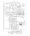
- FIG. 1 is a perspective view showing an infusion pump which is a preferred embodiment of the medical pump of the present invention.
- FIG. 2 is a view of the infusion pump shown in FIG. 1 as viewed from the W direction.
- the infusion pump 1 shown in FIGS. 1 and 2 is an example of a medical pump. As shown in FIG. 2, the infusion pump 1 is provided in the blood vessel of the patient P from the medicine bag 170 filled with the medicine 171 via the clamp 179, the infusion tube 200, and the needle (indwelling needle or catheter for intravascular placement) 172. The liquid can be delivered accurately.
- the drug is also called an infusion.
- An infusion tube is also called an infusion line.
- the infusion pump 1 has a main body cover 2 and a handle 2T, and the handle 2T can be extended in the N direction or stored in the T direction.
- the main body cover 2 is also called a main body, and is integrally formed of a molded resin material having chemical resistance, and can be prevented from entering the infusion pump 1 even if a drug or the like is applied. have.
- the main body cover 2 has the drip-proof treatment structure because the medicine 171 in the medicine bag 170 disposed above spills out or disinfects the disinfecting liquid used in the vicinity. Because there is.
- a display unit 3 and an operation panel unit 4 are arranged on the upper portion 2 ⁇ / b> A of the main body cover 2.
- the display unit 3 is an image display device, and uses, for example, a color liquid crystal display device. This display unit 3 can display not only information notation in Japanese but also information in a plurality of foreign languages as required.
- the display unit 3 is disposed on the upper left side of the upper portion 2 ⁇ / b> A of the main body cover 2 and above the opening / closing cover 5.
- the upper portion 2 ⁇ / b> A of the main body cover 2 is an upper half portion of the main body cover 2.
- the lower part 2 ⁇ / b> B of the main body cover 2 is a lower half part of the main body cover 2.
- a display portion 3 for displaying information and an operation panel portion 4 having a plurality of operation buttons are arranged on the upper portion 2A of the body cover 2 of the infusion pump 1, and a lower portion 2B of the body cover 2 of the infusion pump 1 is This is a region where an infusion tube 200 which is a liquid feeding member for feeding a medicine is arranged.
- the medical worker can perform the liquid feeding operation of the medicine by the infusion pump 1 while confirming the information on the display unit 3 of the upper portion 2A of the main body cover 2.
- the medical staff can operate the operation buttons on the operation panel unit 4 while checking the information on the display unit 3 of the upper portion 2A of the main body cover 2. For this reason, the operability of the infusion pump 1 is good.
- the display unit 3 includes a display column 3B for a scheduled dose (mL) of drug administration, a display column 3C for an accumulated dose (mL) of drug administration, a display column 3D for a charge history, and a flow rate (mL / h).
- a display column 3B for a scheduled dose (mL) of drug administration
- a display column 3C for an accumulated dose (mL) of drug administration
- a display column 3D for a charge history
- a flow rate mL / h
- the display unit 3 can also display a warning message.
- the display unit 3 can change the display from, for example, a “yellow display screen” to a “white display screen” that is a warning screen for medical workers by turning on the backlight of an LED (light emitting diode). it can.
- the operation panel unit 4 is disposed on the right side of the display unit 3 in the upper part 2A of the main body cover 2, and the operation panel unit 4 includes, as an operation button, a lamp 4A (LED that functions as, for example, an operation indicator in the illustrated example. Etc., and blinks or lights green during normal operation, blinks or lights red during abnormal operation), fast-forward switch button 4B, start switch button 4C, stop switch button 4D, menu selection button 4E, power switch 4F, etc. Has been.
- a lamp 4A LED that functions as, for example, an operation indicator in the illustrated example. Etc., and blinks or lights green during normal operation, blinks or lights red during abnormal operation
- fast-forward switch button 4B start switch button 4C
- stop switch button 4D stop switch button 4D
- menu selection button 4E menu selection button 4E
- power switch 4F etc. Has been.
- an opening / closing cover 5 serving as a lid member is provided on the lower portion 2B of the main body cover 2 so as to be openable and closable in the R direction around a rotating shaft 5A.
- the open / close cover 5 is a plate-like lid member that is formed long along the X direction.
- the tube mounting part 50 and the liquid feeding drive part 60 are disposed inside the opening / closing cover 5.
- An infusion tube 200 made of a flexible thermoplastic resin such as soft vinyl chloride is set in the tube mounting portion 50, and the infusion tube 200 is connected to the tube mounting portion 50 by closing the open / close cover 5. , And can be mounted horizontally along the X direction (T direction). Note that the X direction, the Y direction, and the Z direction in FIGS.
- the X direction is parallel to the T direction, which is the liquid feeding direction, and is the left-right direction of the infusion pump 1.
- the Y direction is the front-rear direction of the infusion pump 1.
- FIG. 3 is a perspective view showing a tube mounting portion 50 for opening the opening / closing cover 5 of the infusion pump 1 shown in FIGS. 1 and 2 and mounting the infusion tube 200.
- the tube mounting part 50 and the liquid feeding drive part 60 are provided on the main body lower part 1B side of the infusion pump 1, and the tube mounting part 50 and the liquid feeding drive part 60 are operated with the display part 3.
- a lower portion of the panel portion 4 is provided along the X direction.
- the tube mounting portion 50 can cover the open / close cover 5 with the open / close cover 5 when the open / close cover 5 is closed in the CR direction around the rotation shaft 5A.
- the tube mounting portion 50 includes a bubble sensor 51, an upstream blockage sensor 52, a downstream blockage sensor 53, a tube clamp portion 270, a first infusion tube guide portion 54 at the right side position, and a left side position.
- a second infusion tube guide portion 55 is provided.
- an infusion tube setting direction display unit 150 for clearly displaying the T direction that is the correct liquid feeding direction when the infusion tube 200 is set is provided in the vicinity of the tube mounting unit 50. ing.
- the infusion tube setting direction display unit 150 includes, for example, a plurality of arrows 151.
- the infusion tube setting direction display unit 150 may be printed directly on the lower part of the tube mounting part 50, for example, or may be printed on a seal-like member and attached to the lower part of the tube mounting part 50.
- the infusion tube setting direction display unit 150 is arranged to clearly indicate the liquid feeding direction (T direction) in the correct direction of the medicine 171 by the infusion tube 200 set inside the opening / closing cover 5.
- the infusion tube 200 it is possible to clearly indicate the T direction, which is the direction of drug delivery. For this reason, it can prevent reliably that a medical worker will attach the infusion tube 200 by the reverse direction accidentally.
- the open / close cover 5 is a plate-like member made of a thin molded resin member in order to reduce the weight of the infusion pump 1. Thereby, the weight of the opening / closing cover 5 can be reduced, and the structure can be simplified.
- the opening / closing cover 5 has two hinge portions 2H and 2H that allow the tube mounting portion 50 to be covered so as to be openable and closable along the CS direction and the CR direction about the rotation shaft 5A. It is supported with respect to the main body lower part 2B.
- the two hinge portions 2H and 2H are arranged corresponding to the first hook member 5D and the second hook member 5E, respectively.
- an opening / closing operation lever 260 is provided at the upper right portion on the surface side of the opening / closing cover 5.
- an infusion tube pressing member 500 On the inner surface side of the opening / closing cover 5, an infusion tube pressing member 500, a first hook member 5D, and a second hook member 5E are provided.
- the infusion tube pressing member 500 is disposed as a long rectangular and planar protrusion along the X direction, and the infusion tube pressing member 500 is in a position facing the liquid feeding drive unit 60.
- the infusion tube pressing member 500 has a flat surface in the X direction along the liquid feeding drive unit 60, and the infusion tube pressing member 500 closes the opening / closing cover 5 in the CR direction, A part of the infusion tube 200 is pressed between them.
- the medical worker can set the infusion tube 200 on the lower half of the body of the infusion pump 1 along the horizontal direction while confirming the display content displayed on the display unit 3, and the infusion tube 200 is connected to the tube mounting portion. After being set to 50, the opening / closing cover 5 can cover the infusion tube 200.
- the first hook member 5D and the second hook member 5E are mechanically simultaneously engaged with the fixing portions 1D and 1E on the lower body 1B side, so that the open / close cover 5 is As shown, the tube mounting part 50 of the main body lower part 1B is held in a closed state.
- the first hook member 5D, the second hook member 5E, and the fixing portions 1D, 1E on the main body lower part 1B side constitute a double hook structure portion 300 of the opening / closing cover 5.
- the tube clamp part 270 shown in FIG. 3 clamps and closes the middle part of the infusion tube 200 by closing the open / close cover 5.
- the tube clamp portion 270 is disposed in the vicinity of the left fixed portion 1E and at a position corresponding to the left second hook member 5E.
- the tube clamp portion 270 can block a part of the infusion tube 200 in the middle.
- the first infusion tube guide portion 54 is provided on the right side of the main body lower portion 1B, and the second infusion tube guide portion 55 is provided on the left side of the main body lower portion 1B.
- the first infusion tube guide portion 54 can be held by fitting the upstream side 200A of the infusion tube 200
- the second infusion tube guide portion 55 can be held by fitting the downstream side 200B of the infusion tube 200
- the infusion tube 200 can be held. It is held in the horizontal direction along the X direction.
- the infusion tube 200 held in the horizontal direction is in the T direction along the bubble sensor 51, the upstream block sensor 52, the liquid feed drive unit 60, the downstream block sensor 53, and the tube clamp unit 270. It is fixed by fitting along.
- the second infusion tube guide portion 55 is a groove portion formed in the side surface portion 1 ⁇ / b> S of the main body lower portion 1 ⁇ / b> B in order to detachably hold a part of the downstream side 200 ⁇ / b> B of the infusion tube 200. is there.
- the first infusion tube guide portion 54 and the second infusion tube guide portion 55 are provided in the tube attachment portion 50 so that the infusion tube 200 is not sandwiched between the opening / closing cover 5 and the tube attachment portion 50 and crushed. Can be installed securely.
- the bubble sensor 51 shown in FIG. 3 is a sensor that detects bubbles (air) generated in the infusion tube 200.
- the bubble sensor 51 is an infusion tube from the outside of the infusion tube 200 formed of a thermoplastic resin such as polybutadiene.
- 200 is an ultrasonic sensor for monitoring bubbles contained in a medicine flowing in 200.
- the receiving unit monitors the presence or absence of bubbles by detecting the difference in transmittance.
- the bubble sensor 51 has a pressing member 320 and a receiving member 330.
- the ultrasonic oscillator is disposed on the pressing member 320.
- the ultrasonic wave receiver is disposed on the receiving member 330.
- the upstream blockage sensor 52 shown in FIG. 3 is a sensor that detects whether or not the inside of the infusion tube 200 is blocked on the upstream side 200A of the infusion tube 200, and the downstream blockage sensor 53 is an infusion solution on the downstream side 200B of the infusion tube 200. It is a sensor that detects whether or not the inside of the tube 200 is closed.
- the upstream blockage sensor 52 and the downstream blockage sensor 53 have the same configuration.
- the case where the infusion tube 200 is blocked is, for example, a case where the viscosity of the medicine to be delivered is high or the concentration of the medicine is high.
- pressing members 452 and 453 are provided on the inner surface side of the opening / closing cover 5 at positions corresponding to the upstream closing sensor 52 and the downstream closing sensor 53, respectively.
- the infusion tube 200 of any size among the plural types of infusion tubes 200 having different diameters is attached to the infusion pump 1, when the open / close cover 5 is closed, the upstream side occlusion sensor 52 and the downstream side occlusion sensor 53 are The occlusion state of the infusion tube 200 can be detected.
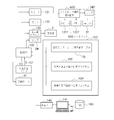
- FIG. 4 shows an electrical configuration example of the infusion pump 1.
- the infusion pump 1 has a control unit 100 that controls judgment and control of the overall operation of the infusion pump 1.
- the liquid feeding drive unit 60 includes a drive motor 61, a cam structure 62 having a plurality of cams driven to rotate by the drive motor 61, and a plurality of fingers moved by the cams of the cam structure 62. It has a finger structure 63 (that is, a peristaltic infusion pump).
- the cam structure 62 has a plurality of cams, for example, a plurality of cams 62A to 62F, and the finger structure 63 has a plurality of fingers 63A to 63F corresponding to the plurality of cams 62A to 62F. .
- the plurality of cams 62A to 62F are arranged with a phase difference from each other, and the cam structure 62 is connected to the output shaft 61A of the drive motor 61.
- the plurality of fingers 63A to 63F are sequentially advanced and retracted by a predetermined stroke in the Y direction by the plurality of eccentric cams 62A to 62F.
- the infusion tube 200 is pressed against the infusion tube holding member 500 of the open / close cover 5 along the T direction. For this reason, the medicine in infusion tube 200 can be sent in the T direction. That is, when the plurality of fingers 63A to 63F are individually driven, the plurality of fingers 63A to 63F sequentially press the outer peripheral surface of the infusion tube 200 along the T direction to feed the medicine in the infusion tube 200. .
- control unit 100 controls the peristaltic motion of the plurality of fingers 63A to 63F, thereby causing the fingers 63A to 63F to move forward and backward in sequence, so that the wave travels, so that the blockage point of the infusion tube 200 is set.
- the infusion tube 200 is squeezed and the medicine is fed into the blood vessel of the patient P through the indwelling needle 172.
- the control unit 100 of the infusion pump 1 employs a CPU (central control unit) chip.
- the control unit 100 uses, for example, a one-chip microcomputer to control the overall operation, and includes a ROM (read only memory) 101, a RAM (random access memory) 102, a nonvolatile memory 103, and a clock. 104.
- the clock 104 can correct the current time by a predetermined operation, and can acquire the current time, measure the elapsed time of a predetermined liquid feeding operation, measure the reference time of liquid feeding speed control, and the like.
- a power switch button 4F includes a power switch button 4F, a power switch 111, a display driver 130 and a display 3, a drive motor 61, a speaker 131, a buzzer 132, a lamp 3W, a bubble sensor 51, and an upstream occlusion sensor. 52, the downstream blockage sensor 53, the communication port 140, the operation panel (operation button) 4, and the information terminal 600 on the nurse center side, and manage and control these peripheral elements.
- the switch 111 supplies power to the control unit 100 from one of the power converter unit 112 and the battery 113 by switching between the power converter unit 112 and the battery 113.
- the power converter unit 112 is connected to a commercial AC power source 115 via an outlet 114.
- the battery 113 is a rechargeable secondary battery such as a lithium ion battery.
- the control unit 100 is also connected to the upstream block sensor 52 and the downstream block sensor 53. Thereby, the control part 100 can also monitor the obstruction
- the information terminal 600 on the nurse center side is placed in the nurse center 650 distant from the infusion pump 1, and the above-described display unit 3, lamp 4A, speaker 131, The display unit 3T, the lamp 3WT, the speaker 131T, and the buzzer 132T are the same as the buzzer 132.
- the display unit driver 130 in FIG. 4 drives the display unit 3 in response to a command from the control unit 100, displays the information content and warning message illustrated in FIG. 2, and turns on the LED (light emitting diode) backlight.
- the display can be changed from a “yellow display screen” to a “white display screen” that is a warning screen for a medical worker. Thereby, the possibility that a medical worker can visually recognize is increased.
- the error display lamp 3 ⁇ / b> W is turned on according to a command from the control unit 100.
- the speaker 131 can notify various warning contents instructed by the control unit 100 by voice.
- the buzzer 132 can warn various warnings by sound according to a command from the control unit 100.
- the display unit 3T is driven by a command from the control unit 100 to display the information content and warning message illustrated in FIG. 2 and to turn on the backlight of the LED (light emitting diode).
- the display can be changed from the “display screen” to a “white display screen” which is a warning screen for the medical staff. Thereby, the possibility that a medical worker can visually recognize is increased.
- the error display lamp 3WT is turned on according to a command from the control unit 100.
- the speaker 131T can notify various warning contents instructed by the control unit 100 by voice.
- the buzzer 132T can warn various warnings by sound according to a command from the control unit 100.
- a downstream block signal S3 indicating that the side is blocked is supplied to the control unit 100.
- the upstream blockage sensor 52 and the downstream blockage sensor 53 can detect a state in which the internal pressure of the infusion circuit exceeds the set pressure in the infusion pump 1 and the medicine cannot be delivered.
- the reason why the internal pressure of the infusion circuit exceeds the set pressure in the infusion pump 1 is that there is a so-called “needle detachment” in which the tip of the infusion needle 172 for infusion shown in FIG.
- needle detachment in which the tip of the infusion needle 172 for infusion shown in FIG.
- the inside of the tube 200 is clogged, a part of the infusion tube 200 is crushed or broken, or a high-viscosity drug is used.
- the control unit 100 includes RS-232C (RS: Recommended Serial Standard; a serial input / output interface of a communication system standardized by EIA (American Electronic Industry Association)), a wired communication system, an infrared communication using a wireless LAN, and the like.
- RS-232C Recommended Serial Standard
- EIA American Electronic Industry Association
- wired communication system an infrared communication using a wireless LAN
- infrared communication using a wireless LAN and the like.
- bidirectional communication with a computer 141 such as a desktop computer is possible through the communication port 140.
- the computer 141 is connected to a drug database (DB) 160, and the drug library MF stored in the drug database 160 is acquired by the control unit 100 via the computer 141 as necessary, and the control unit 100 100 nonvolatile memories 103 can be stored.
- the control unit 100 can display the drug library MF and the like on the display unit 3 shown in FIG.
- the drug information MF includes, for example, drug manufacturer name, drug name, upper and lower limit values of drug administration scheduled amount (mL), upper and lower limit values of flow rate (mL / h), contraindication information, etc. 8 (A) is included.
- the upstream occlusion sensor 52 shown in FIG. 4 detects whether the infusion tube 200 is occluded on the upstream side 200 ⁇ / b> A of the infusion tube 200, and the control unit 100 detects the infusion tube 200.
- This is a sensor for sending an upstream block signal S2 indicating that the upstream side is blocked.
- the downstream blockage sensor 53 detects whether or not the inside of the infusion tube 200 is blocked on the downstream side 200B of the infusion tube 200 (the degree to which the inner diameter and the outer diameter of the infusion tube 200 slightly expand in the radial direction in FIG.
- the upstream blockage sensor 52 and the downstream blockage sensor 53 have the same configuration.
- a case where the downstream side of the infusion tube 200 is blocked a case where a so-called “needle disengagement” in which the tip of the infusion needle 172 for infusion shown in FIG.
- An example of using the downstream occlusion sensor 53 to detect the “needle detachment” phenomenon will be described later.
- FIG. 5 is a block diagram showing a part of the electrical configuration example of the infusion pump 1 shown in FIG. 4 in more detail.
- the non-volatile memory 103 of the control unit 100 shown in FIG. 5 includes an occlusion precaution reference value table TB, an occlusion pressure rapid increase detection processing program PIP for the infusion tube 200, and an occlusion pressure rapid decrease detection processing program PDP for the infusion tube 200. Is remembered.
- the control unit 100 can acquire the occlusion precaution reference value table TB from the medicine database (DB) 160 on the computer 141 side through the communication port 140.
- DB medicine database
- This occlusion precaution is a preventive function of “detecting needle removal at the tip of the indwelling needle 172” using a change in the occlusion pressure in the infusion tube 200.
- Specific examples of the blockage precaution reference value table TB, the blockage pressure rapid increase detection processing program PIP of the infusion tube 200, and the blockage pressure rapid decrease detection process program PDP of the infusion tube 200 will be described later.
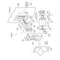
- FIG. 6 is an exploded perspective view showing a structural example of the upstream blockage sensor 52 and the downstream blockage sensor 53. As illustrated in FIG. 6, the upstream blockage sensor 52 and the downstream blockage sensor 53 have the same structure.
- a hole 400 is provided in the surface 50 ⁇ / b> S of the tube mounting portion 50.
- a plastic frame member 401 is fitted into the hole 400, and the frame member 401 has a rectangular opening 402.
- the plastic slider 403 is inserted into the accommodation hole 404 in the hole 400, and the slider 403 has a base 405, a tip 406, and a spring 407.
- the leading end 406 of the slider 403 is fitted into the opening 402.
- One end of the spring 407 is attached to the base 405, and the other end of the spring 407 is attached to the protrusion 409 in the accommodation hole 404.
- a Hall element 410 is disposed on the inner surface of the accommodation hole 404.
- Two magnets 411 and 412 are arranged on the base 405.
- the upstream blockage sensor 52 is simply installed by inserting the frame member 401 into the hole 400 and inserting the base 405 into the opening 402 and the accommodation hole 404 while holding the spring 407.
- the downstream blockage sensor 53 can be easily mounted on the surface 50S of the tube mounting portion 50, and the assembly workability of the upstream blockage sensor 52 and the downstream blockage sensor 53 can be improved.
- pressing members 452 and 453 are provided on the inner surface side of the opening / closing cover 5 at positions corresponding to the upstream closing sensor 52 and the downstream closing sensor 53, respectively.
- the pressing members 452 and 453 have a structure that is pressed to the facing frame member side via a spring 441.
- the pressing member 452 is a first pressing member
- the pressing member 453 is a second pressing member.
- the infusion tube 200 can be The upstream occlusion sensor 52 and the downstream occlusion sensor 53 are pressed against the infusion tube 200 so that the occlusion state of the infusion tube 200 can be accurately detected.
- the upstream blockage sensor 52 and the downstream blockage sensor 53 will be described more specifically.
- the infusion tube 200 is moved between the pressing member 452 (453) and the tip 406 of the slider 403 as shown in FIG. It is sandwiched and held by each urging force 441. If the infusion tube 200 is blocked and the diameter of the infusion tube 200 (the outer diameter and the inner diameter slightly expand), the tip 406 follows the change in the diameter of the infusion tube 200 and the left side in the Y direction. Move to.
- the Hall element 410 detects a change in the magnetic flux and sends the movement amount to the control unit 100 as a signal of the change in the magnetic flux.
- the central axis direction of the spring 441 and the central axis direction of the spring 407 coincide with each other, and the springs 441 and 407 sandwich the infusion tube 200 between the pressing member 452 (453) and the distal end portion 406.
- the occlusion state of the infusion tube 200 can be detected with high accuracy by detecting the movement amount of the slider 403 forming the occlusion sensors 52 and 53.
- the occlusion of the infusion tube 200 downstream from the infusion pump 1 is caused by bending (kinking) of the infusion tube 200 or needle removal from the blood vessel (vein) of the indwelling needle 172 described in detail below.
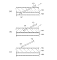
- FIG. 7 shows a state example in which the indwelling needle 172 shown in FIG.
- the pointed tip 197 of the indwelling needle 172 shows the state of the normal indwelling needle 172 inserted and placed in the blood vessel 198 of the patient.
- FIG. 7B and FIG. 7C show an abnormal “needle removal” state of the indwelling needle 172.
- FIG. 7B shows an abnormal insertion state of the indwelling needle 172 in which the distal end 197 of the indwelling needle 172 is out of the blood vessel 198 of the patient P and is positioned in the subcutaneous tissue 199 of the patient P. Yes.
- the distal end 197 of the indwelling needle 172 is disengaged from within the blood vessel 198 of the patient P and completely disengaged from the subcutaneous tissue 199 and the skin 196, not from the subcutaneous tissue 199 of the patient P.
- the abnormal state of the indwelling needle 172 is shown.
- FIG. 8 shows an example of the blocking precaution reference value table TB.
- the block precaution reference value table TB illustrated in FIG. 8A is stored in the nonvolatile memory 103 as shown in FIG.
- the column 1001 of the type of drug in the drug library, the column 1002 of the detection setting level of the blockage state of the infusion tube 200, the column 1003 of the detection judgment value of the blockage pressure sudden increase, and the blockage pressure rapid drop A detection judgment value column 1004 is displayed. As shown in FIG.
- the “detection judgment value M of the closing pressure sudden increase” is a moving average value of about 2 to 3 seconds obtained by the downstream blocking sensor 53 at a sampling interval of every 100 ms, for example. It is a percentage indicating an increase rate (threshold value) with respect to the reference value MN.
- the “decision value N for the sudden decrease in the clogging pressure” is a decrease rate (threshold value) with respect to the latest minimum value obtained by the downstream clogging sensor 53, for example, at a sampling interval of 100 ms. ).
- the concept of “rapid increase” or “rapid decrease” of the occlusion pressure is determined in advance as shown in FIG.
- the detection sensitivity is set to an appropriate sensitivity.
- drug types such as (A) nutrient, (B) antibiotic, (C) antihypertensive, (D) anesthetic, and (E) anticancer drug are listed. Are illustrated.
- the control unit 100 communicates with a computer 141 such as a desktop computer through the communication port 140, thereby allowing the medicine library MF stored in the medicine database 160 to be used. It can be acquired by the control unit 100.
- the types and order of drugs described in the occlusion precaution reference value table TB are merely examples, and the types of drugs and the order of description are not particularly limited.
- Detection setting level 1 is (A) nutrient, detection setting level 2 is (B) antibiotic, detection setting level 3 is (C) antihypertensive, detection setting level 4 is (D) anesthetic, and detection setting level 5 is (E) an anticancer agent.
- the detection judgment value column 1003 for the sudden increase in the obstruction pressure in FIG. 8A shows the detection judgment value M for the sudden increase in the obstruction pressure corresponding to the detection setting level 1 to the detection setting level 5.
- a column 1004 shows the detection judgment value N of the blockage pressure sudden drop corresponding to the detection setting level 1 to the detection setting level 5.
- the detection judgment value M for the blockage pressure sudden increase and the detection judgment value N for the blockage pressure sudden drop are averages obtained by the downstream blockage sensor 53 at a predetermined interval, for example, every 100 ms.
- an increase rate (threshold value) with respect to a value set as a reference value MN at a predetermined interval (every 2 minutes) that is longer than the sampling interval is shown. Percentage.
- the occlusion pressure threshold PP shown in FIG. 8B is a value at which the control unit 100 determines that the infusion tube 200 is occluded, sounds an alarm, and stops liquid feeding. The occlusion pressure threshold PP is corrected according to the environmental temperature. In FIG.
- the detection judgment value M of the occlusion pressure sudden rise is, for example, a threshold of 90% rise from the reference value MN in the detection setting level 1.
- a threshold of 90% rise from the reference value MN in the detection setting level 1 At detection setting level 2, an increase of 80% from the above-mentioned reference value MN is a threshold, at detection setting level 3, a case of an increase of 70% from the above-mentioned reference value MN is a threshold, and at detection setting level 4, an increase of 60% from the above-mentioned reference value MN
- the threshold value is set for the case, and the detection setting level 5 is set with a 50% increase from the reference value MN as a threshold value.
- the detection judgment value N of the closing pressure sudden drop is 100% lower than the reference value MN at the detection setting level 1.
- detection setting level 2 80% lowering from the above-mentioned latest minimum value is a threshold
- 60% lowering from the above-mentioned reference value MN is a threshold
- detection setting level 4 40% from the above-mentioned reference value MN.
- the lowering is set as a threshold
- at the detection setting level 5 20% lowering from the above-described reference value MN is set as a threshold.
- the “needle removal detection (occlusion precaution) When the “)” flag is “ON”, the control unit 100 monitors “detecting needle removal (blocking precaution)”.
- the detection setting level of “needle detachment detection (occlusion precaution)” is, for example, a setting level of a plurality of stages, or a detection setting level from an occlusion pressure detection setting level 1 (low sensitivity).
- the setting of 55 levels is made in advance, and the detection setting level is designated according to the type of medicine from one detection setting level of these 5 levels.
- This “needle detachment detection (occlusion precaution)” is effective only while the medicine is being delivered by the infusion tube 200. Note that the number of levels is not limited to 5, and may be 3 levels.
- the control unit 100 in FIG. 5 is obtained by sampling every 100 ms in accordance with the obstruction pressure sudden increase detection processing program PIP of the infusion tube 200 shown in FIG.
- the obstruction AD analog-digital conversion
- the difference between the obstruction AD value two minutes ago and the current obstruction AD value is greater than or equal to a certain value, ⁇ Occlusion AD value before 2 minutes-Current occlusion AD value> Detection judgment value M of occlusion pressure sudden increase>
- the difference between the occlusion AD value after 2 minutes and the current occlusion AD value is a certain value, that is, ⁇ Occlusion AD value after 2 minutes ⁇ Current occlusion AD value ⁇ Detection judgment value M of occlusion pressure sudden increase>
- the detection judgment value M for the sudden increase in occlusion shown in FIG. 8 employs a value obtained by multiplying the reference value MN at that time by a ratio selected from five levels.
- the control unit 100 in FIG. 5 makes the occlusion pressure abruptly according to the occlusion pressure rapid decrease detection processing program PDP of the infusion tube 200 shown in FIG.
- PDP the occlusion pressure rapid decrease detection processing program
- the occlusion pressure decreases more than a certain amount, that is, ⁇ Current occlusion AD value ⁇ latest minimum AD value ⁇ detection value N of occlusion pressure sudden drop>
- “needle removal detection (blocking precaution)” is displayed on, for example, the display unit 3 shown in FIG. 5, the buzzer 132 is sounded, or the speaker 131 is audibly voiced to the medical staff.
- the threshold value is 20%. If the same specification is used for the detection of the sudden decrease in the obstruction pressure, if the obstruction pressure AD value two minutes ago is in the process of sudden decrease, there is a possibility that “needle removal detection (occlusion precaution)” cannot be performed. There is no way to detect sudden changes. In the case of detecting the sudden decrease in the occlusion pressure, there is no time limit of 2 minutes from the latest minimum AD value to the current occlusion AD value. As the latest minimum AD value, the latest AD value at the time when the AD value starts to increase from the decrease after the infusion pump 1 starts the drug delivery operation is used (the occlusion pressure increases). The latest minimum AD value is obtained as follows.
- FIGS. 9 and 10 in the infusion pump 1, a phenomenon that the tip 197 of the indwelling needle 172 is removed from the blood vessel 198 as shown in FIGS. 7 (A) and 7 (B), so-called “needle”.
- a precaution (preventive measure) function for monitoring an abrupt change in the occlusion pressure will be described although the infusion tube 200 does not reach the occlusion state in order to detect “displacement”.
- FIG. 9 is a flowchart showing an example of monitoring when the occlusion pressure rapidly rises during the delivery of the drug through the infusion tube 200, and FIG. 10 shows the occlusion pressure suddenly during the delivery of the drug through the infusion tube 200.
- step ST1 of FIG. 9 the medical staff inserts the indwelling needle 172 into the blood vessel 198 of the patient P as shown in FIG. And when a medical worker pushes on the power switch 4F shown in FIG. 4 and switches on, the control part 100 will operate the drive motor 61 of the liquid feeding drive part 60, and the cam structure 62 will press the infusion tube 200. Then, the drug is fed into the blood vessel 198 of the patient P through the infusion tube 200 and the indwelling needle 172 as shown in FIG.
- step ST1 in FIG. 9 when the medicine is being delivered to the patient P through the infusion tube 200 and the indwelling needle 172 in FIG. 2, the downstream occlusion sensor 53 in FIG.
- the blockage signal S3 is sent to the control unit 100, and in step ST3 and step ST4, the control unit 100 determines whether or not the blockage pressure in the infusion tube 200 of FIG.
- step ST3 the control unit 100 determines that the occlusion pressure in the infusion tube 200 in FIG. 2 is rapidly increased by the downstream occlusion signal S3.
- step ST4 the control unit 100 determines whether or not the reference value MN
- the detection sensitivity 1 to the detection sensitivity 5 is specified according to the magnitude of the percentage (%) that is an increase rate.
- the detection setting value M for the increase in the occlusion pressure is increased because the detection setting level 5 is the occlusion state.
- the threshold is specified as 50% as a percentage (%).
- the control unit 100 starts from the insertion state of the normal indwelling needle 172 in FIG.
- the distal end 197 of the indwelling needle 172 of 7 (B) has been removed from the blood vessel 198 of the patient P and has been inserted into the subcutaneous tissue 199 of the patient P “An abnormal indwelling needle 172 has been inserted” Judging.
- the control unit 100 sounds a buzzer 132 in FIG. 5 to warn the medical staff that the indwelling needle 172 may be dislodged.
- step ST5-2 the control unit 100 displays a warning on the display unit 3 in FIG. 5 to warn the medical staff that the indwelling needle 172 may be dislodged.
- step ST5-3 the control unit 100 warns the medical staff that there is a possibility that the indwelling needle 172 is dislodged by voice guidance through the speaker 131 of FIG.
- One of these warning means may be used, or a plurality of warning means may be combined.
- the control unit 100 shown in FIG. 5 notifies the information terminal 600 on the nurse center side and rings the buzzer 132 T as necessary in step ST 6. This warns the medical staff that the indwelling needle 172 may be dislodged.
- the control unit 100 displays the information on the display unit 3T in FIG. 5 to warn the medical staff that the indwelling needle 172 may be dislodged, and the control unit 100 performs FIG. The medical staff is warned through voice guidance through the speaker 131T that the indwelling needle 172 may be dislodged.
- the lamp 3WT is turned on to warn that the indwelling needle 172 may be dislodged.
- warning means may be used, or a plurality of warning means may be combined.
- the control unit 100 removes the distal end 197 of the indwelling needle 172 of FIG. 7B from the blood vessel 198 of the patient P from the normal insertion state of the indwelling needle 172 of FIG. If it has been inserted into the subcutaneous tissue 199 of P, a warning is given to the medical staff using warning means, but in step ST7, the liquid feeding operation of the drug in the infusion pump 1 is continued without being stopped, After the medical staff confirms the state of the needle, the medicine feeding operation is stopped if necessary by the judgment of the medical staff.
- step ST8 the control unit 100 determines that the occlusion pressure in the infusion tube 200 of FIG. 2 is rapidly decreasing based on the downstream occlusion signal S3.
- step ST9 the control unit 100 determines that the latest minimum The detection sensitivity 1 to the detection sensitivity 5 is specified according to the magnitude of the percentage (%) that is a reduction rate with respect to the AD value. For example, when the type of drug in the drug library MF shown in FIG.
- the detection setting value N for the occlusion pressure sudden rise is the reference setting level 5 because the detection setting level 5 is the occlusion
- a percentage (%) that is an increase rate with respect to the value MN is specified as 50% as a threshold value.
- step ST9 of FIG. 10 if ⁇ current occlusion AD value ⁇ latest minimum AD value ⁇ detection value N of occlusion pressure sudden drop> is satisfied, the insertion state of the normal indwelling needle 172 shown in FIG. From FIG. 7C, the tip 197 of the indwelling needle 172 is not inside the subcutaneous tissue 199 of the patient P, but completely outside the subcutaneous tissue 199 and the skin 196. It has become "state”. Accordingly, in step ST10-1, the control unit 100 sounds a buzzer 132 in FIG. 5 to warn the medical staff that the indwelling needle 172 may be dislodged. At the same time, in step ST10-2, the control unit 100 displays a warning on the display unit 3 in FIG.
- step ST10-3 the control unit 100 warns the medical staff that there is a possibility that the indwelling needle 172 has come off the needle through the speaker 131 of FIG.
- One of these warning means may be selected, or a plurality of means may be combined.
- the control unit 100 shown in FIG. 5 notifies the information terminal 600 on the nurse center side and rings the buzzer 132T as necessary in step ST11. To warn healthcare professionals. At the same time, the control unit 100 displays the information on the display unit 3T in FIG. 5 to warn the medical staff that the indwelling needle 172 may be dislodged, and the control unit 100 performs FIG. The medical staff is warned by voice through the speaker 131T that there is a possibility that the indwelling needle 172 has come off. In addition to this, the lamp 3WT is turned on to warn that the indwelling needle 172 may be dislodged.
- warning means may be selected, or a plurality of means may be combined.
- the control unit 100 removes the distal end 197 of the indwelling needle 172 of FIG. 7C from the inside of the blood vessel 198 of the patient P from the insertion state of the normal indwelling needle 172 of FIG. If it is out of the skin of P, the health care worker is warned by using a warning means, but in step ST12, the medicine feeding operation in the infusion pump 1 is continued without being stopped. After confirming the state of the needle, if necessary, the medicine feeding operation is stopped according to the judgment of the medical staff. In step ST8, when the occlusion pressure does not drop rapidly, the process returns to step ST3 in FIG. 9 and the subsequent steps are executed from step ST3.
- an anticancer drug is delivered into a patient's blood vessel by infusion over about 3 to 4 hours.
- An infusion pump 1 is a medical pump for injecting a drug by indwelling a distal opening of an indwelling catheter or indwelling needle communicating with an infusion tube in a patient's vein.
- a drive motor for feeding the drug through the infusion tube and the needle, a block sensor for detecting a blockage pressure of the infusion tube when the drug is fed, and a downstream of the medical pump.
- the control unit can detect that the tip of the needle has been removed from the inside of the blood vessel (needle removal) and reliably warn the medical staff.
- the control unit determines that the occlusion pressure suddenly increases or the control unit determines that the occlusion pressure suddenly decreases, the control unit continues the liquid feeding operation without stopping the operation of the drive motor. Let As a result, the liquid supply of the medicine is continued without immediately stopping the operation of the drive motor. Therefore, after the medical worker confirms the state of the needle, the liquid supply operation of the medicine is stopped at the judgment of the medical worker. Can be made.
- the warning means is at least one of a display unit that displays warning contents, a speaker that warns the warning contents by voice, and a buzzer that issues warnings. I can inform you. Since the warning means is arranged at the medical pump and the terminal arranged at the nurse center, it can be surely applied not only to the medical staff around the medical pump but also to the medical staff packed in the nurse center. Therefore, it is possible to stop the liquid feeding operation of the medicine by stopping the drive motor.
- a display unit and an operation panel unit having operation buttons are arranged on the upper part of the main body of the medical pump, and a lower part of the main body of the medical pump is an area where a liquid feeding member for feeding a medicine is arranged It is.
- the medical worker can perform the liquid feeding operation of the medicine by the medical pump while confirming the information on the display unit on the upper part of the main body.
- the medical worker can operate the operation buttons on the operation panel unit while confirming the information on the display unit on the upper part of the main body.
- the present invention is not limited to the above embodiment, and various modifications can be made without departing from the scope of the claims.
- the embodiment of the medical pump of the present invention is a peristaltic infusion pump 1, but is not limited to this, and may be a roller-type infusion pump as another embodiment of the medical pump of the present invention.
- the occlusion AD value is a positive value, but may be a negative value. In that case, ⁇ in the above condition becomes ⁇ .
- a part of each configuration of the above embodiment can be omitted, or can be arbitrarily combined so as to be different from the above.
Landscapes
- Health & Medical Sciences (AREA)
- Vascular Medicine (AREA)
- Engineering & Computer Science (AREA)
- Anesthesiology (AREA)
- Biomedical Technology (AREA)
- Heart & Thoracic Surgery (AREA)
- Hematology (AREA)
- Life Sciences & Earth Sciences (AREA)
- Animal Behavior & Ethology (AREA)
- General Health & Medical Sciences (AREA)
- Public Health (AREA)
- Veterinary Medicine (AREA)
- Infusion, Injection, And Reservoir Apparatuses (AREA)
Priority Applications (1)
| Application Number | Priority Date | Filing Date | Title |
|---|---|---|---|
| PCT/JP2012/006213 WO2014049657A1 (fr) | 2012-09-27 | 2012-09-27 | Pompe à usage médical |
Applications Claiming Priority (1)
| Application Number | Priority Date | Filing Date | Title |
|---|---|---|---|
| PCT/JP2012/006213 WO2014049657A1 (fr) | 2012-09-27 | 2012-09-27 | Pompe à usage médical |
Publications (1)
| Publication Number | Publication Date |
|---|---|
| WO2014049657A1 true WO2014049657A1 (fr) | 2014-04-03 |
Family
ID=50387126
Family Applications (1)
| Application Number | Title | Priority Date | Filing Date |
|---|---|---|---|
| PCT/JP2012/006213 Ceased WO2014049657A1 (fr) | 2012-09-27 | 2012-09-27 | Pompe à usage médical |
Country Status (1)
| Country | Link |
|---|---|
| WO (1) | WO2014049657A1 (fr) |
Cited By (1)
| Publication number | Priority date | Publication date | Assignee | Title |
|---|---|---|---|---|
| WO2018181810A1 (fr) * | 2017-03-29 | 2018-10-04 | テルモ株式会社 | Pompe à seringue |
Citations (3)
| Publication number | Priority date | Publication date | Assignee | Title |
|---|---|---|---|---|
| JPS59225067A (ja) * | 1983-06-03 | 1984-12-18 | アトム株式会社 | 輸液装置 |
| JP2010075540A (ja) * | 2008-09-26 | 2010-04-08 | Terumo Corp | 輸液漏れ検出装置 |
| JP2011200430A (ja) * | 2010-03-25 | 2011-10-13 | Terumo Corp | 血管外漏出検知装置及び輸液装置 |
-
2012
- 2012-09-27 WO PCT/JP2012/006213 patent/WO2014049657A1/fr not_active Ceased
Patent Citations (3)
| Publication number | Priority date | Publication date | Assignee | Title |
|---|---|---|---|---|
| JPS59225067A (ja) * | 1983-06-03 | 1984-12-18 | アトム株式会社 | 輸液装置 |
| JP2010075540A (ja) * | 2008-09-26 | 2010-04-08 | Terumo Corp | 輸液漏れ検出装置 |
| JP2011200430A (ja) * | 2010-03-25 | 2011-10-13 | Terumo Corp | 血管外漏出検知装置及び輸液装置 |
Cited By (1)
| Publication number | Priority date | Publication date | Assignee | Title |
|---|---|---|---|---|
| WO2018181810A1 (fr) * | 2017-03-29 | 2018-10-04 | テルモ株式会社 | Pompe à seringue |
Similar Documents
| Publication | Publication Date | Title |
|---|---|---|
| JP6207516B2 (ja) | 輸液ポンプ | |
| JP6023200B2 (ja) | 輸液ポンプ | |
| JP6433294B2 (ja) | 輸液ポンプ | |
| JP6240620B2 (ja) | 点滴プローブと点滴プローブを備える輸液ポンプ | |
| WO2012144219A1 (fr) | Pompe de perfusion | |
| WO2014049656A1 (fr) | Pompe de perfusion | |
| JP6914848B2 (ja) | 医療用ポンプ及びその制御方法 | |
| JP6069333B2 (ja) | 医療用ポンプ | |
| JP5996843B2 (ja) | 輸液ポンプ | |
| JP5805415B2 (ja) | 輸液ポンプ | |
| JP5897815B2 (ja) | 輸液ポンプ | |
| JP6285369B2 (ja) | 輸液ポンプ | |
| JP5740187B2 (ja) | 輸液ポンプ | |
| JP6276823B2 (ja) | 輸液ポンプ | |
| WO2014049657A1 (fr) | Pompe à usage médical | |
| JP2018157934A (ja) | クランプ形態検知システム及びクランプ形態検知装置 | |
| WO2014045328A1 (fr) | Pompe de perfusion | |
| WO2014030184A1 (fr) | Pompe à perfusion | |
| JP2012200422A (ja) | 輸液ポンプ | |
| WO2014045323A1 (fr) | Pompe médicale | |
| HK1189840B (zh) | 输液泵 | |
| WO2014020636A1 (fr) | Pompe à perfusion |
Legal Events
| Date | Code | Title | Description |
|---|---|---|---|
| 121 | Ep: the epo has been informed by wipo that ep was designated in this application |
Ref document number: 12885287 Country of ref document: EP Kind code of ref document: A1 |
|
| NENP | Non-entry into the national phase |
Ref country code: DE |
|
| 122 | Ep: pct application non-entry in european phase |
Ref document number: 12885287 Country of ref document: EP Kind code of ref document: A1 |
|
| NENP | Non-entry into the national phase |
Ref country code: JP |