WO2014049831A1 - Dispositif de mesure et procédé de mesure de concentration de fluide - Google Patents
Dispositif de mesure et procédé de mesure de concentration de fluide Download PDFInfo
- Publication number
- WO2014049831A1 WO2014049831A1 PCT/JP2012/075082 JP2012075082W WO2014049831A1 WO 2014049831 A1 WO2014049831 A1 WO 2014049831A1 JP 2012075082 W JP2012075082 W JP 2012075082W WO 2014049831 A1 WO2014049831 A1 WO 2014049831A1
- Authority
- WO
- WIPO (PCT)
- Prior art keywords
- light
- concentration
- fluid
- locations
- intensity
- Prior art date
- Legal status (The legal status is an assumption and is not a legal conclusion. Google has not performed a legal analysis and makes no representation as to the accuracy of the status listed.)
- Ceased
Links
Images


Classifications
-
- G—PHYSICS
- G01—MEASURING; TESTING
- G01N—INVESTIGATING OR ANALYSING MATERIALS BY DETERMINING THEIR CHEMICAL OR PHYSICAL PROPERTIES
- G01N21/00—Investigating or analysing materials by the use of optical means, i.e. using sub-millimetre waves, infrared, visible or ultraviolet light
- G01N21/84—Systems specially adapted for particular applications
- G01N21/85—Investigating moving fluids or granular solids
-
- G—PHYSICS
- G01—MEASURING; TESTING
- G01N—INVESTIGATING OR ANALYSING MATERIALS BY DETERMINING THEIR CHEMICAL OR PHYSICAL PROPERTIES
- G01N21/00—Investigating or analysing materials by the use of optical means, i.e. using sub-millimetre waves, infrared, visible or ultraviolet light
- G01N21/17—Systems in which incident light is modified in accordance with the properties of the material investigated
- G01N21/25—Colour; Spectral properties, i.e. comparison of effect of material on the light at two or more different wavelengths or wavelength bands
- G01N21/27—Colour; Spectral properties, i.e. comparison of effect of material on the light at two or more different wavelengths or wavelength bands using photo-electric detection ; circuits for computing concentration
-
- G—PHYSICS
- G01—MEASURING; TESTING
- G01N—INVESTIGATING OR ANALYSING MATERIALS BY DETERMINING THEIR CHEMICAL OR PHYSICAL PROPERTIES
- G01N21/00—Investigating or analysing materials by the use of optical means, i.e. using sub-millimetre waves, infrared, visible or ultraviolet light
- G01N21/17—Systems in which incident light is modified in accordance with the properties of the material investigated
- G01N21/59—Transmissivity
Definitions
- the present invention relates to a method and an apparatus for measuring the concentration of a fluid flowing in a light-transmitting pipe line based on the Lambert-Beer law.
- the measuring method and measuring apparatus measure the concentration of a processing liquid as a fluid for cleaning a semiconductor wafer.
- a plurality of measuring bodies are provided in the middle of the processing liquid supply pipe, and a light transmitting portion in which the optical path length of the light passing through the processing liquid is different is provided in each measuring body, according to the properties of the processing liquid.
- the light from the light source is supplied to the light transmission part of the optical path length, the light transmitted through the processing liquid in the light transmission part is received by the photodetector, the intensity of the light is examined, and the Lambert- The concentration of the processing solution is obtained based on Beer's law.
- the optical path length in each light transmitting portion is strictly known, and therefore the fluid concentration is determined using a calculation formula in which the optical path length is set in advance. It can be easily obtained.
- a fluid such as blood or a chemical flowing in a light-transmitting conduit such as a resin tube or a glass tube, it is expected that it will be extremely useful in the field of medicine or the like. .
- the fluid concentration measuring method of the present invention is a tube having a light transmissive tube wall.
- the fluid concentration measuring method of the present invention is a tube having a light transmissive tube wall.
- the light intensity and fluid when the light from each of the plurality of light supply locations is received at the plurality of light receiving locations are obtained by obtaining a plurality of relational expressions indicating the relationship with the concentration of the liquid, and simultaneously connecting the relational expressions for the plurality of light supply points. Is obtained, and based on the relational expression, the concentration of the fluid is obtained from the light intensity at the plurality of light receiving locations, and is output.
- the fluid concentration measuring device is a device for measuring the concentration of a fluid flowing in a pipe line having a light-transmitting tube wall.
- a light source that supplies light into the conduit at light supply locations located at a plurality of locations on the surface of the conduit arranged adjacent to each other along the extending direction of the conduit;
- Each of the light receiving locations on the surface of the pipeline located on the opposite side of the diameter direction of the pipeline with respect to those light supply locations, respectively, is supplied in the wall of the pipeline and in the pipeline
- a light receiving element that receives light passing through the fluid and outputs a signal indicating the intensity of the light; Based on the Lambert-Beer law from the light intensity at these light receiving locations, the light intensity and fluid when the light from each of the plurality of light supply locations is received at the plurality of light receiving locations, respectively.
- fluid concentration output means for obtaining and outputting the concentration of the fluid from the intensity of light at the plurality of light receiving locations, It is characterized by comprising.
- the fluid concentration measuring method of the present invention when measuring the concentration of a fluid such as blood or a chemical solution flowing in a light-transmitting conduit such as a resin tube or a glass tube, in the extending direction of the conduit.
- a light source supplies light into the pipeline at two or more light supply locations on the surface of the pipeline that are lined up adjacent to each other, and the diameter direction of the pipeline with respect to the light supply locations Receiving light that has been supplied and passed through the inside of the pipe and the fluid flowing in the pipe at two or more light receiving places on the surface of the pipe located on the opposite side Then, based on the Lambert-Beer law from the light intensity at these light receiving locations, the light from each of the plurality of light supply locations is received at each of the plurality of light receiving locations.
- the relationship between the light intensity and the fluid concentration A plurality of relational expressions, and by making the relational expressions simultaneous with respect to the plurality of light supply locations, cancel the term of the wall thickness of the pipe line, etc., and the light intensity at the plurality of light receiving locations. Since a relational expression showing the relation with the concentration of the fluid is obtained, and based on the relational expression, the concentration of the fluid is obtained from the light intensity at the plurality of light receiving points and output, so the wall thickness of the pipe line, the emission intensity, etc. Even if it is unknown or changes, it is possible to measure the concentration of fluid such as blood and chemicals flowing through the pipe line with high accuracy.
- the fluid concentration measuring device of the present invention in the device for measuring the concentration of the fluid flowing in the light-transmitting conduit such as a resin tube or a glass tube, adjacent to each other along the extending direction of the conduit
- the light source supplies light into the pipes at two or more light supply points on the surface of the pipes arranged side by side, and the opposite side in the diameter direction of the pipes with respect to those light supply points
- Each of the light receiving elements at a plurality of light receiving points on the surface of the pipe located at the position receives the light that has been supplied and passed through the wall of the pipe and the fluid in the pipe.
- a signal indicating the intensity of the light is output, and the fluid concentration output means outputs light from each of the plurality of light supply points based on the Lambert-Beer law from the light intensity at the light receiving points.
- the fluid concentration output means is obtained and stored in advance using a relational expression indicating the relationship between the light intensity and the fluid concentration at the plurality of light receiving locations.
- a relational expression indicating the relationship between the light intensity and the fluid concentration at the plurality of light receiving locations.
- the fluid concentration may be obtained and output from the light intensity at the plurality of light receiving locations, By using such a table, it is possible to easily obtain and output the fluid concentration in a short time from the light intensity at a plurality of light receiving points.
- the fluid concentration output means is previously obtained by an experiment based on a relational expression indicating a relationship between the light intensity and the fluid concentration at the plurality of light receiving portions.
- the concentration of the fluid is obtained from the light intensity at the plurality of light receiving locations and output. Even if such a table is used, the concentration of the fluid can be easily obtained and output in a short time from the intensity of light at a plurality of light receiving locations.
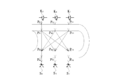
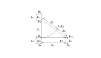
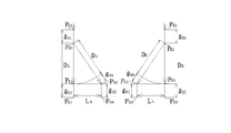
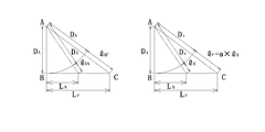
- FIGS. 1 to 10 are explanatory views sequentially showing measurement and calculation procedures in one embodiment of the fluid concentration measuring method of the present invention.
- the fluid concentration measurement method of this embodiment measures the concentration of blood as a fluid flowing in a substantially transparent resin tube as a conduit having a light transmissive tube wall.
- light output from three light emitting diodes KA, KB, and KC serving as light sources is arranged at three locations on the surface of the resin tube arranged adjacent to each other along the extending direction of the resin tube.
- the tube wall on the side near the light emitting diodes of the resin tube, the blood in the resin tube, and the tube wall on the far side (opposite side) from the light emitting diodes.
- three light sensors SA, SB at three light receiving points on the surface of the resin tube located on the opposite side of the diameter direction of the resin tube with respect to those light supply points. Shall reach and C, the path reaching the light sensor, the most light intensity is considered strong portion, three light emitting diodes KA as a light source, KB, the light output from each of KC, Consider a model that follows each path.
- the extinction coefficient of blood in the resin tube is ⁇ H
- the concentration is CH
- the distance between the sensors is set as sensor SA-SB and SB-SC: LN
- sensor SA-SC LF
- the inner diameter of the resin tube is PA2-PA3: DA
- PB2-PB3 DB
- PC2-PC3 DC.
- Equations (13), (14), and (17) Since LF and LN are fixed values, and IAF, IAG, ICF, ICG, IAN, IBN, and IBG are measured values, these equations are composed of only measured values and fixed values.
- the blood concentration CH in the resin tube is: It becomes.
- the blood concentration (hemat (red blood cell) concentration) CH can be obtained. Because of the complexity of calculations and the scattering of light by red blood cells in real blood, the Lambert-Beer law is extended to apply the modified Lambert-Beer law applied to media with light scattering In this case as well, it is natural that exact calculation is possible. However, since the calculation becomes more complicated, the measurement method of this embodiment simplifies the process and does not include a mathematical function command.
- the concentration is directly determined by the (central processing unit)
- the following terms including the actual blood concentration CH and the light intensity measurement value that is, The conversion table between the blood concentration CH value using the value of the blood pressure as an index is created in advance and stored in the memory, and when the light intensity measurement value is obtained, the conversion table and the light emitting diodes KA, KB are obtained from those values.
- the value of blood concentration CH is read using the known fixed value such as the value of blood extinction coefficient ⁇ H corresponding to the emission wavelength of KC, and is output.
- FIG. 11 is a block diagram showing an embodiment of the fluid concentration measuring apparatus of the present invention that can implement the measuring method of the above embodiment.
- the fluid concentration measuring apparatus of this embodiment is a light transmissive tube.
- Light having a wavelength of, for example, a wavelength near 590 nm is approximately equal in both the oxygenated hemoglobin of arterial blood and the deoxygenated hemoglobin of venous blood in the resin tube T at three light supply locations on the surface of T.
- Three light emitting diodes 1 (KA, KB, KC in FIG.
- each light sequentially output from the three light emitting diodes 1 is connected to the tube wall of the resin tube T near the light emitting diodes 1 and the resin tube T.
- Microcomputers that have passed through the blood in the tube and the tube walls on the far side (opposite side) from the light-emitting diodes 1 and arrived at the three photosensors 2, respectively, and the output signals of the three photosensors 2 have been input 3 obtains the value of the blood concentration CH by a simple calculation using the conversion table and the fixed value described above, and displays it on the display device 4. Therefore, the microcomputer 3 and the display device 4 correspond to fluid concentration output means.
- the intensity of the light emitted by each of the three light emitting diodes 1 is adjusted as appropriate so that the output signals of the three photosensors 2 have an appropriate level.
- an optical sensor for monitoring is added to each light emitting diode 1 so that the output signals of the three optical sensors 2 are appropriate and stable, and these are also connected to the microcomputer 3,
- the intensity of light emitted from each of the three light emitting diodes 1 may be feedback controlled by the microcomputer 3.
- the microcomputer 3 calculates the light intensity indicated by the output signals of the three photosensors 2 at the three light receiving points based on the Lambert-Beer law. For each of the three light supply locations, three relational expressions showing the relationship between the light intensity and the blood concentration when receiving light from the three light receiving locations are obtained. Based on the relational expression showing the relationship between the light intensity at the three light receiving points and the blood concentration, which is obtained by combining the light supply points, the blood concentration is calculated from the light intensity at the three light receiving points. Therefore, even if the inner diameter, wall thickness, and light emission intensity of the resin tube T are unknown or change, the concentration of blood flowing through the resin tube T can be measured with high accuracy. Rukoto can.
- the microcomputer 3 uses the relational expression indicating the relationship between the light intensity and the fluid concentration at the three light receiving locations stored in the memory in advance. Using a table indicating the relationship between the light intensity at three light receiving locations and the blood concentration obtained separately, the blood concentration is determined from the light intensity at the three light receiving locations and output from the display device 4. Therefore, the blood concentration can be easily obtained and output in a short time from the light intensity at the three light receiving points.
- this invention is not limited to the above-mentioned example, It can change suitably within the description range of a claim,
- blood concentration is obtained from the light intensity at three light receiving locations and output.
- the blood concentration is calculated from the light intensity and output using a relational expression showing the relationship between the light intensity and the blood concentration at the three light receiving points.
- the modified Lambert-Beer law considering light scattering is applied as the Lambert-Beer law, and the relationship between the light intensity and blood concentration at the three light-receiving points is applied. For the relation Good.
- the microcomputer as the fluid concentration output means is based on the relationship.
- 3 is a table showing the relationship between the light intensity at the plurality of light receiving points and the actual fluid concentration, which is obtained and stored in advance by experiments, and the fluid intensity is calculated from the light intensity at the plurality of light receiving points.
- the density may be obtained and output.
- light having a wavelength of about 590 nm is used as light having substantially the same absorbance as that of both oxygenated hemoglobin of arterial blood and deoxygenated hemoglobin of venous blood.
- light having a wavelength in the vicinity of 520 nm, 550 nm, 570 nm, or 805 nm may be used.
- a light emitting diode is used as a light source.
- a laser diode may be used, and a resin tube is used as a conduit.
- a glass tube may be used as the conduit, and in the method and apparatus of the above embodiment, the concentration of blood as a liquid is measured, but instead, it can be used for measuring the concentration of other liquids.
- the concentration of blood as a liquid is measured, but instead, it can be used for measuring the concentration of other liquids.
- the light intensity at the three light receiving points is likely to be different depending on the thickness of the tube wall. Therefore, it is preferable.
- light is sequentially supplied from the three light supply locations so that the light from the three light supply locations is not mixed, and the light from each of the light supply locations is received at three locations.
- the light intensity is obtained by receiving light at each location, but instead of this, for example, the light from three light supply locations is modulated at different frequencies, and the lights are supplied simultaneously.
- the light received at each light receiving location may be filtered at those frequencies (modulation lock-in method) so that the intensity of the light from each light supply location is separated and processed.
- light is supplied at three light supply locations, and light from each light supply location is received at each of the three light receiving locations to determine the light intensity.
- light is supplied at two or four or more light supply locations, and light from each light supply location is received at two or four or more light receiving locations corresponding to each light supply location.
- the light intensity may be obtained, and when there are two light supply points and two light receiving points, the wall thickness of the pipe line is known, so that the error is absorbed, for example, for mounting a pipe such as a resin ground tube. can do.
- the wall thickness and inner diameter of the pipe line are known, so that the blood concentration to be examined can be obtained as in the above embodiment.
- the measurement accuracy can be further enhanced by averaging the obtained results.
- the fluid concentration measuring method of the present invention when measuring the concentration of fluid such as blood or chemicals flowing in a light-transmitting conduit such as a resin tube or a glass tube, in the extending direction of the conduit.
- a light source supplies light into the pipeline at two or more light supply locations on the surface of the pipeline that are lined up adjacent to each other, and the diameter direction of the pipeline with respect to the light supply locations Receiving light that has been supplied and passed through the inside of the pipe and the fluid flowing in the pipe at two or more light receiving places on the surface of the pipe located on the opposite side Then, based on the Lambert-Beer law from the light intensity at these light receiving locations, the light from each of the plurality of light supply locations is received at each of the plurality of light receiving locations.
- the fluid concentration measuring device of the present invention in the device for measuring the concentration of the fluid flowing in the light-transmitting conduit such as a resin tube or a glass tube, adjacent to each other along the extending direction of the conduit
- the light source supplies light into the pipes at two or more light supply points on the surface of the pipes arranged side by side, and the opposite side in the diameter direction of the pipes with respect to those light supply points
- Each of the light receiving elements at a plurality of light receiving points on the surface of the pipe located at the position receives the light that has been supplied and passed through the wall of the pipe and the fluid in the pipe.
- a signal indicating the intensity of the light is output, and the fluid concentration output means outputs light from each of the plurality of light supply points based on the Lambert-Beer law from the light intensity at the light receiving points.
Landscapes
- Physics & Mathematics (AREA)
- Health & Medical Sciences (AREA)
- Life Sciences & Earth Sciences (AREA)
- Chemical & Material Sciences (AREA)
- Analytical Chemistry (AREA)
- Biochemistry (AREA)
- General Health & Medical Sciences (AREA)
- General Physics & Mathematics (AREA)
- Immunology (AREA)
- Pathology (AREA)
- Engineering & Computer Science (AREA)
- Mathematical Physics (AREA)
- Theoretical Computer Science (AREA)
- Spectroscopy & Molecular Physics (AREA)
- Investigating Or Analysing Materials By Optical Means (AREA)
Abstract
La présente invention vise à mesurer de manière hautement précise la concentration d'un fluide tel qu'un produit chimique ou du sang s'écoulant à l'intérieur d'une conduite même si une intensité d'émission de lumière, l'épaisseur de paroi de la conduite ou similaire n'est pas claire ou varie. A cet effet, la présente invention est caractérisée par le fait que : lors de la mesure de la concentration d'un fluide s'écoulant à l'intérieur d'une conduite ayant une paroi de tube d'émission de lumière, une lumière est alimentée depuis une source lumineuse dans la conduite au niveau d'une pluralité de positions d'alimentation en lumière sur la surface de la conduite agencées adjacentes les unes aux autres le long de la direction d'extension de la conduite ; au niveau de chacune d'une pluralité de positions de réception de lumière sur la surface de la conduite positionnées au niveau du côté inverse dans la direction diamétrale de la conduite depuis les positions d'alimentation en lumière, la lumière arrivante est reçue, laquelle a été alimentée et a traversé l'intérieur du fluide s'écoulant à l'intérieur de la conduite et l'intérieur de la paroi de la conduite, et l'intensité de la lumière est déterminée ; sur la base de la loi de Beer-Lambert à partir de l'intensité de la lumière au niveau des positions de réception de lumière, une pluralité d'expressions relationnelles sont déterminées indiquant la relation entre la concentration du fluide et l'intensité de lumière lors de la réception d'une lumière provenant de chacune de la pluralité de positions d'alimentation en lumière respectivement au niveau de la pluralité de positions de réception de lumière ; au moyen de la combinaison des expressions relationnelles par rapport à la pluralité de positions d'alimentation en lumière, une expression relationnelle est déterminée indiquant la relation entre la concentration du fluide et l'intensité de lumière au niveau de la pluralité de positions de réception de lumière ; et sur la base de l'expression relationnelle, la concentration du fluide est déterminée à partir de l'intensité de lumière au niveau de la pluralité de positions de réception de lumière, et est délivrée en sortie.
Priority Applications (3)
| Application Number | Priority Date | Filing Date | Title |
|---|---|---|---|
| PCT/JP2012/075082 WO2014049831A1 (fr) | 2012-09-28 | 2012-09-28 | Dispositif de mesure et procédé de mesure de concentration de fluide |
| PCT/JP2013/054664 WO2014050162A1 (fr) | 2012-09-28 | 2013-02-25 | Procédé de mesure et dispositif de mesure de concentration de fluide |
| JP2014538208A JP6053807B2 (ja) | 2012-09-28 | 2013-02-25 | 流体濃度の測定方法および測定装置 |
Applications Claiming Priority (1)
| Application Number | Priority Date | Filing Date | Title |
|---|---|---|---|
| PCT/JP2012/075082 WO2014049831A1 (fr) | 2012-09-28 | 2012-09-28 | Dispositif de mesure et procédé de mesure de concentration de fluide |
Publications (1)
| Publication Number | Publication Date |
|---|---|
| WO2014049831A1 true WO2014049831A1 (fr) | 2014-04-03 |
Family
ID=50387293
Family Applications (2)
| Application Number | Title | Priority Date | Filing Date |
|---|---|---|---|
| PCT/JP2012/075082 Ceased WO2014049831A1 (fr) | 2012-09-28 | 2012-09-28 | Dispositif de mesure et procédé de mesure de concentration de fluide |
| PCT/JP2013/054664 Ceased WO2014050162A1 (fr) | 2012-09-28 | 2013-02-25 | Procédé de mesure et dispositif de mesure de concentration de fluide |
Family Applications After (1)
| Application Number | Title | Priority Date | Filing Date |
|---|---|---|---|
| PCT/JP2013/054664 Ceased WO2014050162A1 (fr) | 2012-09-28 | 2013-02-25 | Procédé de mesure et dispositif de mesure de concentration de fluide |
Country Status (2)
| Country | Link |
|---|---|
| JP (1) | JP6053807B2 (fr) |
| WO (2) | WO2014049831A1 (fr) |
Families Citing this family (1)
| Publication number | Priority date | Publication date | Assignee | Title |
|---|---|---|---|---|
| CN115266589B (zh) * | 2022-08-02 | 2025-03-18 | 湖南伊鸿健康科技有限公司 | 血红蛋白浓度测量方法、系统及智能设备 |
Citations (4)
| Publication number | Priority date | Publication date | Assignee | Title |
|---|---|---|---|---|
| JPS6357566U (fr) * | 1986-09-30 | 1988-04-16 | ||
| JPH0638947A (ja) * | 1992-03-31 | 1994-02-15 | Univ Manitoba | 血液の分光測光分析法及び該装置 |
| JPH0854339A (ja) * | 1994-08-10 | 1996-02-27 | Fuji Electric Co Ltd | コロイド状物質を含む溶媒の色度、濁度の測定方法と その装置 |
| JP2003021594A (ja) * | 2002-05-20 | 2003-01-24 | Aloka Co Ltd | 検体検査装置 |
Family Cites Families (4)
| Publication number | Priority date | Publication date | Assignee | Title |
|---|---|---|---|---|
| JPS54159280A (en) * | 1978-06-06 | 1979-12-15 | Nec Corp | Turbidity measuring apparatus |
| CA2092372C (fr) * | 1992-04-24 | 2000-03-14 | Klaus W. Berndt | Methodes et appareil de detection de microorganismes dans des flacons d'hemoculture |
| US5601080A (en) * | 1994-12-28 | 1997-02-11 | Coretech Medical Technologies Corporation | Spectrophotometric blood analysis |
| WO2005054825A1 (fr) * | 2003-12-03 | 2005-06-16 | Pulp And Paper Reseach Institute Of Canada | Procédé et dispositif de lumière polarisante pour la détermination de l'épaisseur de paroi et d'orientation de fibrilles de fibres cellulosiques |
-
2012
- 2012-09-28 WO PCT/JP2012/075082 patent/WO2014049831A1/fr not_active Ceased
-
2013
- 2013-02-25 WO PCT/JP2013/054664 patent/WO2014050162A1/fr not_active Ceased
- 2013-02-25 JP JP2014538208A patent/JP6053807B2/ja active Active
Patent Citations (4)
| Publication number | Priority date | Publication date | Assignee | Title |
|---|---|---|---|---|
| JPS6357566U (fr) * | 1986-09-30 | 1988-04-16 | ||
| JPH0638947A (ja) * | 1992-03-31 | 1994-02-15 | Univ Manitoba | 血液の分光測光分析法及び該装置 |
| JPH0854339A (ja) * | 1994-08-10 | 1996-02-27 | Fuji Electric Co Ltd | コロイド状物質を含む溶媒の色度、濁度の測定方法と その装置 |
| JP2003021594A (ja) * | 2002-05-20 | 2003-01-24 | Aloka Co Ltd | 検体検査装置 |
Also Published As
| Publication number | Publication date |
|---|---|
| JP6053807B2 (ja) | 2016-12-27 |
| WO2014050162A1 (fr) | 2014-04-03 |
| JPWO2014050162A1 (ja) | 2016-08-22 |
Similar Documents
| Publication | Publication Date | Title |
|---|---|---|
| US7884933B1 (en) | Apparatus and method for determining analyte concentrations | |
| US7420658B2 (en) | Method and device for measurements in blood | |
| EP2988113B1 (fr) | Dispositif de mesure de concentration de fluide | |
| US9308306B2 (en) | Self calibrating blood chamber | |
| JP6599855B2 (ja) | 変形可能な容器内の物質の濃度を求める方法 | |
| US20150241347A1 (en) | Nondispersive infrared micro-optics sensor for blood alcohol concentration measurements | |
| CN107666860A (zh) | 光电体积描记装置 | |
| JP2007509718A5 (fr) | ||
| JP2016523373A5 (fr) | ||
| ITMI20090926A1 (it) | Apparato e metodo per misure spettrofotometriche di parametri del sangue. | |
| WO2014049831A1 (fr) | Dispositif de mesure et procédé de mesure de concentration de fluide | |
| CN107533004B (zh) | 透射光强度测定单元 | |
| CN107741404A (zh) | 一种血液净化系统用尿素含量监测装置 | |
| JPWO2020085236A5 (ja) | 濃度測定装置及び濃度測定方法 | |
| EP3936035A1 (fr) | Dispositif de mesure d'informations biologiques | |
| US9357955B2 (en) | Portable analytical device and system | |
| TWI551269B (zh) | 攜帶型分析裝置以及系統 | |
| CN116763305B (zh) | 基于ecmo的红细胞比容和血氧饱和度检测方法及装置 | |
| Surkova et al. | Low-cost optical sensor for real-time blood loss monitoring during transurethral surgery | |
| JP6161065B2 (ja) | 血液情報測定装置及び測定方法 | |
| US12578263B1 (en) | Optical wastewater pretreat sensor | |
| Shepherd et al. | An oximeter for measuring hemoglobin concentration and oxygen content | |
| US12140463B1 (en) | Method including optical detection | |
| EP4517298A1 (fr) | Dispositif et procédé de mesure de valeur de caractéristique optique | |
| Sheira | A model for determining and monitoring the saturation level of oxygen in the blood |
Legal Events
| Date | Code | Title | Description |
|---|---|---|---|
| 121 | Ep: the epo has been informed by wipo that ep was designated in this application |
Ref document number: 12885621 Country of ref document: EP Kind code of ref document: A1 |
|
| NENP | Non-entry into the national phase |
Ref country code: DE |
|
| 122 | Ep: pct application non-entry in european phase |
Ref document number: 12885621 Country of ref document: EP Kind code of ref document: A1 |
|
| NENP | Non-entry into the national phase |
Ref country code: JP |