WO2014050642A1 - 自動車用ガラスラン - Google Patents
自動車用ガラスラン Download PDFInfo
- Publication number
- WO2014050642A1 WO2014050642A1 PCT/JP2013/075091 JP2013075091W WO2014050642A1 WO 2014050642 A1 WO2014050642 A1 WO 2014050642A1 JP 2013075091 W JP2013075091 W JP 2013075091W WO 2014050642 A1 WO2014050642 A1 WO 2014050642A1
- Authority
- WO
- WIPO (PCT)
- Prior art keywords
- vehicle
- door
- glass run
- side wall
- door frame
- Prior art date
- Legal status (The legal status is an assumption and is not a legal conclusion. Google has not performed a legal analysis and makes no representation as to the accuracy of the status listed.)
- Ceased
Links
Images



Classifications
-
- B—PERFORMING OPERATIONS; TRANSPORTING
- B60—VEHICLES IN GENERAL
- B60J—WINDOWS, WINDSCREENS, NON-FIXED ROOFS, DOORS, OR SIMILAR DEVICES FOR VEHICLES; REMOVABLE EXTERNAL PROTECTIVE COVERINGS SPECIALLY ADAPTED FOR VEHICLES
- B60J10/00—Sealing arrangements
- B60J10/70—Sealing arrangements specially adapted for windows or windscreens
- B60J10/74—Sealing arrangements specially adapted for windows or windscreens for sliding window panes, e.g. sash guides
- B60J10/76—Sealing arrangements specially adapted for windows or windscreens for sliding window panes, e.g. sash guides for window sashes; for glass run channels
-
- B—PERFORMING OPERATIONS; TRANSPORTING
- B60—VEHICLES IN GENERAL
- B60R—VEHICLES, VEHICLE FITTINGS, OR VEHICLE PARTS, NOT OTHERWISE PROVIDED FOR
- B60R13/00—Elements for body-finishing, identifying, or decorating; Arrangements or adaptations for advertising purposes
- B60R13/06—Sealing strips
-
- B—PERFORMING OPERATIONS; TRANSPORTING
- B60—VEHICLES IN GENERAL
- B60J—WINDOWS, WINDSCREENS, NON-FIXED ROOFS, DOORS, OR SIMILAR DEVICES FOR VEHICLES; REMOVABLE EXTERNAL PROTECTIVE COVERINGS SPECIALLY ADAPTED FOR VEHICLES
- B60J10/00—Sealing arrangements
- B60J10/80—Sealing arrangements specially adapted for opening panels, e.g. doors
- B60J10/86—Sealing arrangements specially adapted for opening panels, e.g. doors arranged on the opening panel
- B60J10/88—Sealing arrangements specially adapted for opening panels, e.g. doors arranged on the opening panel mounted on, or integral with, the glass-run seals
-
- B—PERFORMING OPERATIONS; TRANSPORTING
- B60—VEHICLES IN GENERAL
- B60J—WINDOWS, WINDSCREENS, NON-FIXED ROOFS, DOORS, OR SIMILAR DEVICES FOR VEHICLES; REMOVABLE EXTERNAL PROTECTIVE COVERINGS SPECIALLY ADAPTED FOR VEHICLES
- B60J5/00—Doors
- B60J5/04—Doors arranged at the vehicle sides
- B60J5/0401—Upper door structure
- B60J5/0402—Upper door structure window frame details, including sash guides and glass runs
Definitions
- the present invention relates to an automotive glass run that is attached to the upper side of a door frame and guides the raising and lowering of the door glass.
- a glass run 110 for guiding the raising and lowering of the door glass 5 is attached to the inner periphery of the door frame 2 of the door 1 of the automobile.
- the glass run 110 is attached in the channel 103 of the door frame 2 to guide the raising and lowering of the door glass 5 and to seal between the door glass 5 and the door frame 2. .
- the glass run 110 is formed from a straight line portion 111 formed by extrusion molding and a glass run corner portion 112 formed by molding to match the shape of the corner portion 2h of the door frame 2.
- the straight portion 111 includes a glass run upper side portion 113 attached to the upper side portion 2 b of the door frame 2, a glass run front side vertical side portion 114 attached to the front side vertical side portion 2 a of the door frame 2, and the door frame 2.
- the glass run rear side vertical side portion 115 is attached to the rear side vertical side portion 2a.
- the seal between the door 1 and the vehicle body is an opening that is attached to the door weather strip 150 attached to the outer periphery of the door panel and the door frame 2 and / or the flange of the opening of the vehicle body. It is made by a trim weather strip (not shown).
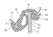
- the glass run upper side 113 of the main body of the glass run 110 has a substantially U-shaped cross section made up of the vehicle outer side wall 120, the vehicle inner side wall 130, and the bottom wall 140.
- a vehicle outer side seal lip 121 is provided so as to extend from the vicinity of the front end of the vehicle outer side wall 120 toward the inside of the main body having a substantially U-shaped cross section.
- a vehicle inner side seal lip 131 is also provided on the vehicle inner side wall 130 so as to extend from the vicinity of the front end thereof toward the inside having a substantially U-shaped cross section.
- a vehicle outer side cover lip 123 is formed in parallel to the outer surface of the vehicle outer side wall 120 from the vicinity of the front end of the vehicle outer side wall 120, and a vehicle inner side cover lip 133 is formed in parallel from the vicinity of the front end of the vehicle inner side wall 130 to the outer surface of the vehicle inner side wall 130. Is formed.
- the vehicle outer side wall 120, the vehicle inner side wall 130, and the bottom wall 140 of the main body of the glass run 110 are fitted into the flange portions of the door outer panel 2c and the door inner panel 2d of the door frame 2 (see, for example, Patent Document 1).
- the flange portion of the door outer panel 2c is inserted between the vehicle outer side wall 120 and the vehicle outer cover lip 123, and the flange portion of the door inner panel 2d is inserted between the vehicle inner side wall 130 and the vehicle inner cover lip 133. Inserted.
- the bottom wall 140 is held by the flat portion of the door reinforcing panel 2e.
- the door reinforcing panel 2 e is partially mounted on the upper side of the door frame 2 because it is difficult to fully mount the door reinforcing panel 2 e and the weight increases. There is only.
- an object of the present invention is to provide a glass run in which no gap is generated between the cover lip and the door panel even when the door glass is moved up and down.
- the present invention of claim 1 is an automotive glass run that is attached to the inner periphery of a door frame of an automobile door and guides the raising and lowering of the door glass, and the glass run is formed by extrusion molding. Connect the glass run upper side part attached to the upper side part of the door frame, the glass run vertical side part attached to the vertical side part of the door frame, the glass run upper side part and the glass run vertical side part formed by molding.
- the upper side of the glass run is a glass run having a substantially U-shaped cross section comprising a bottom wall, a vehicle outer side wall extending from the vehicle outer side edge of the bottom wall, and a vehicle inner side wall extending from the vehicle inner side edge of the bottom wall.
- the vehicle outer side wall and the vehicle inner side wall are provided with a vehicle outer side seal lip and a vehicle inner side seal lip that extend toward the inner side of the substantially U-shaped cross section of the main body, respectively.
- the vehicle outer side surface and the vehicle inner side surface of the door glass are sealed by the lip, and the vehicle outer side cover lip is formed from the tip of the vehicle outer side wall to the outer surface side with respect to the substantially U-shaped cross section.
- Car interior cover lip is formed,
- the flange part at the tip of the outer panel of the door frame is held in the vehicle outer holding groove formed between the vehicle outer side wall and the vehicle outer cover lip, and the vehicle inner side holding formed between the vehicle inner side wall and the vehicle inner cover lip. Hold the flange part at the end of the inner panel of the door frame in the groove,
- An automotive glass run characterized in that a locking projection for locking the front end of the flange portion is formed at the back of at least one of the vehicle outer side holding groove and the vehicle inner side holding groove.
- the upper side of the glass run includes a bottom wall, a vehicle outer side wall extending from the vehicle outer side edge of the bottom wall, and a vehicle inner side wall extending from the vehicle inner side edge of the bottom wall. It has a glass run body that is roughly U-shaped. For this reason, when the door is closed, the front end of the door glass is stored inside the glass run having a substantially U-shaped cross section of the main body including the outer side wall, the inner side wall, and the bottom wall at the upper side of the door frame. The door glass can be securely held.
- the vehicle exterior side and the vehicle interior side are the vehicle interior side and vehicle interior side of the vehicle with the door closed.
- a vehicle outer side seal lip and a vehicle inner side seal lip are provided on the vehicle outer side wall and the vehicle inner side wall, respectively, extending toward the inside of the substantially U-shaped cross section of the main body.
- the vehicle outer surface and the vehicle inner surface are sealed. For this reason, when the door glass is raised by the vehicle outer side seal lip and the vehicle inner side seal lip, both the seal lips contact the door glass, and the vehicle outer side seal lip and the vehicle inner side seal lip contact the door frame.
- a seal between the door glass can be made.
- a vehicle outer cover lip is formed on the outer surface side of the substantially U-shaped cross section from the front end of the vehicle outer side wall, and a vehicle inner cover lip is formed on the outer surface side of the substantially inner U-shaped cross section from the front end of the vehicle inner side wall. For this reason, it is possible to cover the flange portion of the door outer panel with the vehicle outer cover lip, cover the flange portion of the door inner panel with the vehicle inner cover lip, and cover the flange portion with the cover lip. good.
- the flange part at the tip of the outer panel of the door frame is held in the vehicle outer holding groove formed between the vehicle outer side wall and the vehicle outer cover lip, and the vehicle inner side holding formed between the vehicle inner side wall and the vehicle inner cover lip.
- the flange portion at the tip of the inner panel of the door frame is held in the groove. For this reason, the flange part of a door outer panel can be hold
- a locking projection that locks the front end of the flange portion is formed at the back of at least one of the vehicle outer side holding groove and the vehicle inner side holding groove, the front end of the door glass pushes up the bottom wall, and the vehicle outer side wall and the vehicle inner side wall are Even when pulled, the locking projection is locked by the tip of the flange, and the cover lip on the side where the locking projection is formed is not pulled, and a gap is created between the cover lip and the door panel. There is no.
- the locking projection has a mountain shape and one surface is formed as an inclined surface, a bent portion is formed at the tip of the flange portion of the door frame, and the bent portion and the inclined surface are planar. It is the glass run for automobiles which contacts.
- the locking projection has a mountain shape, one surface is formed as an inclined surface, a bent portion is formed at the tip of the flange portion of the door frame, and the bent portion and the inclined surface are planarly contacted. Touch. For this reason, the bent portion at the tip of the flange portion and the inclined surface are in strong contact with each other, the contact area is large, and the locking projection does not move away from the bent portion of the flange portion, so that the cover lip is not pulled. There is no gap between the cover lip and the door panel.
- a glass run for an automobile in which a retaining projection is formed on the vehicle outer side wall or the vehicle inner side wall slightly opened from the back of the vehicle outer side holding groove or the vehicle inner side holding groove formed with the locking projection. It is.
- the retaining protrusion is formed on the vehicle outer side wall or the vehicle inner side wall slightly open from the back of the vehicle outer side holding groove or the vehicle inner side holding groove where the locking protrusion is formed. For this reason, even when the glass run is shifted downward from the flange portion on the upper side of the door frame, the tip of the flange portion is locked to the retaining projection and the glass run is not detached from the door frame.
- an automotive glass run in which the locking projection is formed in a vehicle interior holding groove formed between the vehicle interior side wall and the vehicle interior cover lip.
- the locking projection is formed in the vehicle inner side holding groove formed between the vehicle inner side wall and the vehicle inner cover lip, the vehicle inner cover formed larger than the vehicle outer cover lip. The lip is not deformed, and there is no gap between the vehicle interior cover lip and the inner panel.
- the present invention of claim 5 is an automotive glass run in which a door reinforcing panel is attached to a part of the upper side of the door frame and the bottom wall of the upper side of the glass run is in contact with the door reinforcing panel.
- the glass run can be securely held by the flange. Since a locking projection that locks the front end of the flange portion is formed at the back of at least one of the vehicle outer side holding groove and the vehicle inner side holding groove, even if the front end of the door glass pushes up the bottom wall, the locking projection portion remains the flange portion.
- the cover lip on the side where the locking projections are formed is not pulled, and a gap is not generated between the cover lip and the door panel.
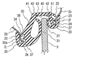
- FIG. 5 is a cross-sectional view of a state in which the glass run according to the embodiment of the present invention is mounted on the upper side portion of the door frame, and is a cross-sectional view along AA in FIG. 4.
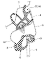
- FIG. 5 is a cross-sectional view of a state in which the glass run according to the embodiment of the present invention is mounted on the upper side portion of the door frame and the front end of the door glass pushes up the bottom wall, and is a cross-sectional view along AA in FIG. .
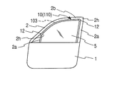
- FIG. 5 is a front view of the front door 1 of the automobile
- FIG. 4 is a front view of the glass run 10 of the front door attached to the door frame 2 of the door 1.
- the door frame 2 is provided on the upper part of the door 1, and the door glass 5 is attached so that raising / lowering is possible. That is, a glass run 10 is attached to the inner periphery of the door frame 2 to guide the raising and lowering of the door glass 5 and to seal between the door glass 5 and the door frame 2.
- the glass run 10 is attached to the straight portion 11 formed by extrusion molding as a whole and the corner portion 2h of the door frame 2, and is formed by molding by connecting the straight portion 11 described above. Corner portion 12.
- the straight portion 11 includes a glass run upper side portion 13 attached to the upper side portion 2 b of the door frame 2, a glass run rear side vertical side portion 15 attached to the rear side vertical side portion 2 a of the door frame 2, and the door frame 2.
- the glass run front side vertical side portion 14 is formed.
- the corners 12 are formed by forming the extruded parts by molding at the front and rear corners so as to have a shape corresponding to the door frame 2 and connecting the straight parts 11. Yes.
- the corner portion 12 of the glass run 10 is attached to the corner portion 2 h of the door frame 2.
- the seal between the door 1 and the vehicle body opening peripheral edge 6 is formed by the door weather strip 50 attached to the outer periphery of the door panel and door frame 2 against the vehicle body opening peripheral edge 6.
- the door frame 2 and the door glass 5 are sealed with a glass run 10 in contact and sealed.
- a glass run 10 is attached to the door outer panel flange 2f and the door inner panel flange 2j which are the ends of the door outer panel 2c and the door inner panel 2d. Is installed.
- the door reinforcement panel 2e is attached to the upper side 2b of the door frame 2 in part.
- the bottom wall 40 of the glass run 10 is held by the door reinforcement panel 2e in the portion where the door reinforcement panel 2e is attached, and the door glass 5 rises. Even if the bottom wall 40 is pushed, the bottom wall 40 is not pushed into the door frame 2 greatly.
- the bottom wall 40 is not held by the door reinforcing panel 2e in the portion where the door reinforcing panel 2e of the upper side 2b of the door frame 2 is not attached.
- the vehicle outer side wall 20 and the vehicle inner side wall 30 are pulled, and the vehicle outer side cover lip 23 and the vehicle inner side wall are pulled.
- the cover lip 33 may be lifted from the door inner panel 2d and the door inner panel 2d.
- the cross-sectional shape of the glass run upper side portion 13 of the glass run 10 attached to the upper side portion 2 b of the door frame 2 is from the vehicle outer side edge portion of the bottom wall 40 and the bottom wall 40 to the bottom wall 40.
- the vehicle outer side wall 20 extending downward (substantially downward in FIG. 1) at a substantially vertical or slightly obtuse angle, and the vehicle inner side wall extending downward from the vehicle inner side edge of the bottom wall 40 to the bottom wall 40 at a substantially vertical or slightly obtuse angle.
- 30 in a substantially U-shaped cross section As will be described later, the vehicle interior side wall 30 is larger than the vehicle exterior side wall 20 and is thick, and the substantially U-shaped cross section is formed in an asymmetric shape with a large vehicle interior.
- the vehicle outer side wall 20, the vehicle inner side wall 30 and the bottom wall 40, which are the main body of the glass run 10, are basically the same in both the portion attached to the upper side 2 b of the door frame 2 and the portion attached to the vertical side 2 a.
- the cross section has a substantially U-shaped cross section.
- the vehicle exterior and vehicle interior refer to the vehicle interior and vehicle interior of the vehicle with the door closed, and the upper and lower directions indicate the vertical direction of the vehicle. Is.
- the vehicle interior side wall 30 is formed thicker and larger than the vehicle exterior side wall 20. For this reason, the glass run 10 can be held on the side surface of the door frame 2.
- a vehicle interior cover lip 33 is formed from the front end of the vehicle interior side wall 30 to the outer surface side of the substantially U-shaped cross section. For this reason, the door inner panel flange portion 2j at the tip of the door inner panel 2d can be covered with the vehicle inner side cover lip 33, and the appearance is good.
- a vehicle interior holding groove 37 is formed between the vehicle interior side wall 30 and the vehicle interior cover lip 33.
- the door inner panel flange portion 2j is inserted into the vehicle interior holding groove 37 and held. As shown in FIG. 1, the front end of the door inner panel flange portion 2j is slightly bent in the vehicle outer direction to form a bent portion 2k.
- the base portion of the vehicle interior cover lip 33 is slightly extended in the vehicle interior direction from the vehicle interior side wall 22 and then bent upward to form an L-shaped cross section. For this reason, the vehicle interior holding groove 37 has a planar space in the back part.
- a vehicle interior locking projection 35 is formed in a planar portion at the back of the vehicle interior holding groove 37.
- the vehicle inner side locking projection 35 is formed in a mountain shape, and the surface on the side of the vehicle inner side wall 30 is in contact with the bent portion 2k of the door inner panel flange portion 2j formed by bending. 35a is formed.
- the vehicle inner side latching protrusion contact surface 35a is formed as an inclined surface in a planar shape.
- the bending angle of the bent portion 2k of the door inner panel flange portion 2j and the inclination angle of the vehicle inner side locking projection contact surface 35a are substantially the same when the door inner panel flange portion 2j is inserted into the vehicle inner holding groove 37. It is preferable to form.
- the bent portion 2k of the door inner panel flange portion 2j and the inboard engagement protrusion abutting surface 35a abut in a plane.
- the bent portion 2k and the vehicle inner side locking projection contact surface 35a have a large contact area, and come into strong contact so that the door inner panel flange portion 2j does not separate from the vehicle inner side locking projection portion 35.
- the vehicle inner side locking projection 35 is formed in the vehicle inner side holding groove 37 formed between the vehicle inner side wall 30 and the vehicle inner side cover lip 33, the vehicle inner side cover lip formed larger than the vehicle outer side cover lip 23 is formed. There is no large gap between the inner cover lip 33 and the door inner panel 2d without the deformation of the 33.
- a retaining protrusion 36 is formed on the inner side wall 30 slightly on the opening side from the inner side of the inner holding groove 37. Even when the glass run 10 is shifted downward from the door inner panel flange portion 2j of the upper side 2b of the door frame 2, the bent portion 2k of the door inner panel flange portion 2j is locked to the retaining projection 36, and the vehicle inner side wall It is possible to prevent the glass run 10 from being detached from the door frame 2 by stopping the downward movement of the 30.
- the vehicle interior holding lip 34 was formed on the outer surface of the vehicle interior side wall 30 corresponding to the tip of the vehicle interior cover lip 33.
- the base portion of the door inner panel flange portion 2j is sandwiched between the vehicle inner side holding lip 34 and the vehicle inner side cover lip 33. For this reason, the vehicle inner side wall 30 side of the glass run 10 is held by the door inner panel 2d.
- a vehicle interior seal lip 31 extends obliquely from the front end of the vehicle interior side wall 30 in an internal direction having a substantially U-shaped cross section of the main body of the glass run 10. Since the vehicle interior seal lip 31 is longer and thicker than the vehicle exterior seal lip 21 described later, when the door glass 5 enters the glass run 10, the door glass 5 is positioned on the vehicle exterior side. The step difference between the door frame 2 and the door glass 5 can be reduced. For this reason, air resistance and wind noise are reduced, which is preferable in terms of design.
- the vehicle exterior side wall 20 of the glass run upper side portion 13 is formed in a substantially plate shape in cross section.
- a vehicle outer side seal lip 21 extends from the vicinity of the front end of the vehicle outer side wall 20 toward the inside of the main body having a substantially U-shaped cross section.
- the vehicle outer side wall 20 is thinner and smaller than the vehicle inner side wall 30.
- the vehicle outer side cover lip 23 extends in parallel from the front end of the vehicle outer side wall 20 toward the outside of the vehicle outer side wall 20 in the substantially U-shaped cross section, that is, along the vehicle outer side wall 20 in the vehicle outer direction. Yes. For this reason, the door outer panel flange 2f at the tip of the door outer panel 2c can be covered with the vehicle outer side cover lip 23, and the appearance is good.
- a vehicle exterior holding groove 27 is formed between the vehicle exterior side wall 20 and the vehicle exterior cover lip 23.
- the door outer panel flange portion 2 f is inserted and held in the vehicle outer side holding groove 27.
- the distal end of the door outer panel flange portion 2f is not bent and formed unlike the distal end of the door inner panel flange portion 2j, but is the same as the door inner panel 2d.
- a bent portion may be provided.
- a locking projection portion can be formed in the vehicle outer side holding groove 27, similarly to the vehicle inner side holding groove 37.
- the locking projection portion abuts on the bent portion of the door outer panel flange portion 2f in a plane, and the door outer panel flange portion 2f extends from the locking projection portion. Since it does not leave, even if the front end of the door glass 5 pushes the bottom wall 40, the vehicle outer cover lip 23 is not pulled, and a gap is generated between the vehicle outer cover lip 23 and the door outer panel 2c. Absent.
- a vehicle outer side first holding lip 24 and a vehicle outer side second holding lip 25 are formed on the outer surface side of the vehicle outer side wall 20.
- the vehicle outer side first holding lip 24 and the vehicle outer side second holding lip 25 abut against the door outer panel flange portion 2f, and can securely lock the vehicle outer side wall 20 to the door outer panel flange portion 2f. It is possible to seal between the vehicle outer side wall 20 and the door outer panel flange portion 2f.
- an outer side seal lip 21 extends obliquely toward the inside of the main body of the glass run 10 having a substantially U-shaped cross section.
- the bottom wall 40 is formed in a substantially plate shape, and a bottom wall groove portion 42 is formed so as to be easily bent at a continuous portion between the vehicle inner side wall 30 and the vehicle outer side wall 20. Adjacent to the bottom wall groove 42, bottom wall holding lips 41, 41 are formed on the inner surface side of the bottom wall 40. The bottom wall holding lips 41, 41 are in contact with the vicinity of the roots of the vehicle outer side wall 20 and the vehicle inner side wall 30, respectively, and prevent the vehicle outer side wall 20 and the vehicle inner side wall 30 from falling in the internal direction having a substantially U-shaped cross section. is doing.
- thermoplastic elastomer In the molding of the straight portion 11 of the glass run 10, synthetic rubber and thermoplastic elastomer are used as the molding material.
- EPDM rubber is used for synthetic rubber
- polyolefin-based elastomer is used for thermoplastic elastomer.
- synthetic rubber it is conveyed to a vulcanizing tank after extrusion and heated by hot air or high frequency to vulcanize.
- thermoplastic elastomer it is cooled and solidified. Thereafter, it is cut to a predetermined length to produce an extruded part.
- the molded portion of the corner portion 12 of the glass run 10 is molded by cutting the extruded member produced as described above into a predetermined dimension at a substantially right angle to the longitudinal direction, and the end of the cut extruded portion.
- the mold forming part is sandwiched between molds to be molded, and a solid material for forming the mold forming part is injected into the cavity of the mold.
- the cross-sectional shape of the molded part is substantially the same as the cross-sectional shape of the extruded part. It is preferable to use the same type of molding material as that used for the extruded part. In the case of a thermoplastic elastomer, since the injected material is melted when injected into the mold, the extruded part and the molded part are integrally fused by the heat and pressure.
- the corner portion 12 of the glass run 10 is preferably formed of EPDM rubber or an olefin-based thermoplastic elastomer.
- the corner portion 12 of the glass run 10 is formed of an olefinic thermoplastic elastomer.
- the same kind of material is used, and the adhesion between the straight portion 11 and the corner portion 12 of the glass run 10 is good.
- both are olefin-based materials, have good weather resistance, can be pulverized at the same time, and can be easily recycled.
- vulcanization is not required, and therefore production is easy.
- synthetic rubber the mold is heated and vulcanized after being poured into the mold. At this time, since the extrusion molding part and the molding part use the same material or the same kind of material, vulcanization adhesion can be performed, and they can be fixed integrally.
Landscapes
- Engineering & Computer Science (AREA)
- Mechanical Engineering (AREA)
- Seal Device For Vehicle (AREA)
Description
本発明は、ドアフレームの上辺部に取付けられて、ドアガラスの昇降を案内する自動車用ガラスランに関するものである。
図5に示すように、自動車のドア1のドアフレーム2の内周にドアガラス5の昇降を案内するガラスラン110が取付けられている。
従来、ガラスラン110は、図5に示すように、ドアフレーム2のチャンネル103内に取付けられて、ドアガラス5の昇降を案内するとともにドアガラス5とドアフレーム2との間をシールしている。
従来、ガラスラン110は、図5に示すように、ドアフレーム2のチャンネル103内に取付けられて、ドアガラス5の昇降を案内するとともにドアガラス5とドアフレーム2との間をシールしている。
さらに、ガラスラン110は、図4に示すように、押出成形により成形された直線部111と型成形によってドアフレーム2のコーナー部2hの形状に合わせて形成されたガラスランコーナー部112から形成されている。
直線部111は、ドアフレーム2の上辺部2bに取付けられるガラスラン上辺部113と、ドアフレーム2のフロント側の縦辺部2aに取付けられるガラスランフロント側縦辺部114と、ドアフレーム2のリヤ側の縦辺部2aに取付けられるガラスランリヤ側縦辺部115から構成されている。
直線部111は、ドアフレーム2の上辺部2bに取付けられるガラスラン上辺部113と、ドアフレーム2のフロント側の縦辺部2aに取付けられるガラスランフロント側縦辺部114と、ドアフレーム2のリヤ側の縦辺部2aに取付けられるガラスランリヤ側縦辺部115から構成されている。
なお、ドア1と車体との間のシールは、図3に示すように、ドアパネルおよびドアフレーム2の外周に取付けられたドアウエザストリップ150および/または車体の開口部のフランジに取付けられたオープニングトリムウエザストリップ(図示せず)によりなされている。
ガラスラン110の本体のガラスラン上辺部113は、図6に示すように、車外側側壁120と、車内側側壁130と、底壁140からなる断面略コ字状をなしている。車外側側壁120の先端付近から車外側シールリップ121が本体の断面略コ字状の内側に向けて延出するように設けられている。また、車内側側壁130にもその先端付近から車内側シールリップ131が断面略コ字状の内側に向けて延出するように設けられている。さらに、車外側側壁120の先端付近から車外側側壁120の外面に並行に車外側カバーリップ123が形成され、車内側側壁130の先端付近から車内側側壁130の外面に並行に車内側カバーリップ133が形成されている。
ガラスラン110の本体の車外側側壁120、車内側側壁130と底壁140はドアフレーム2のドアアウターパネル2c、ドアインナーパネル2dのフランジ部分にはめ込まれる(例えば、特許文献1参照。)。
このとき、ドアアウターパネル2cのフランジ部分は、車外側側壁120と車外側カバーリップ123の間に挿入され、ドアインナーパネル2dのフランジ部分は、車内側側壁130と車内側カバーリップ133の間に挿入される。底壁140はドア補強パネル2eの平面部分で保持される。
このとき、ドアアウターパネル2cのフランジ部分は、車外側側壁120と車外側カバーリップ123の間に挿入され、ドアインナーパネル2dのフランジ部分は、車内側側壁130と車内側カバーリップ133の間に挿入される。底壁140はドア補強パネル2eの平面部分で保持される。
しかしながら、図4に示すように、ドア補強パネル2eは、ドアフレーム2の上辺において、ドア補強パネル2eを全面的に装着することが困難であり、重量も増加するため、部分的に装着されているのみである。
このため、図7に示すように、ドアガラス5が上昇して、ドアガラス5の先端が底壁140に当接して、底壁140を押し上げたときに、ドア補強パネル2eが装着されていないドアフレーム2の上辺部2bに取付けられたガラスラン110の底壁140は、ドアガラス5の先端に押し上げられて、車外側側壁120と車内側側壁130が引っ張られて、車外側カバーリップ123と車内側カバーリップ133がドアアウターパネル2cとドアインナーパネル2dから浮き上がり、隙間(図7におけるX)が生じ、見栄えが低下するという問題があった。
そこで、本発明は、ドアガラスの昇降によってもカバーリップとドアパネルとの間に隙間が生じないガラスランを提供することを目的としている。
上記課題を解決するために請求項1の本発明は、自動車ドアのドアフレームの内周に取付け、ドアガラスの昇降を案内する自動車用ガラスランであって、ガラスランは、押出成形により成形されドアフレームの上辺部に装着されるガラスラン上辺部と、ドアフレームの縦辺部に装着されるガラスラン縦辺部と、型成形により成形されガラスラン上辺部とガラスラン縦辺部を接続し、ドアフレームのコーナー部に装着されるコーナー部を有する自動車用ガラスランにおいて、
ガラスラン上辺部は、底壁と該底壁の車外側側縁部から延びる車外側側壁と、底壁の車内側側縁部から延びる車内側側壁とからなる断面略コ字形をなすガラスランの本体を備え、車外側側壁と車内側側壁には、それぞれ本体の断面略コ字状の内側に向かって延出する車外側シールリップと車内側シールリップを設け、車外側シールリップと車内側シールリップによりドアガラスの車外側面及び車内側面をシールし、車外側側壁の先端から断面略コ字形に対する外面側に車外側カバーリップが形成され、車内側側壁の先端から断面略コ字形に対する外面側に車内側カバーリップが形成され、
車外側側壁と車外側カバーリップの間に形成された車外側保持溝にドアフレームのアウターパネルの先端のフランジ部を保持し、車内側側壁と車内側カバーリップの間に形成された車内側保持溝にドアフレームのインナーパネルの先端のフランジ部を保持し、
車外側保持溝と車内側保持溝の少なくとも一方の奥にフランジ部の先端を係止する係止突起部を形成したことを特徴とする自動車用ガラスランである。
ガラスラン上辺部は、底壁と該底壁の車外側側縁部から延びる車外側側壁と、底壁の車内側側縁部から延びる車内側側壁とからなる断面略コ字形をなすガラスランの本体を備え、車外側側壁と車内側側壁には、それぞれ本体の断面略コ字状の内側に向かって延出する車外側シールリップと車内側シールリップを設け、車外側シールリップと車内側シールリップによりドアガラスの車外側面及び車内側面をシールし、車外側側壁の先端から断面略コ字形に対する外面側に車外側カバーリップが形成され、車内側側壁の先端から断面略コ字形に対する外面側に車内側カバーリップが形成され、
車外側側壁と車外側カバーリップの間に形成された車外側保持溝にドアフレームのアウターパネルの先端のフランジ部を保持し、車内側側壁と車内側カバーリップの間に形成された車内側保持溝にドアフレームのインナーパネルの先端のフランジ部を保持し、
車外側保持溝と車内側保持溝の少なくとも一方の奥にフランジ部の先端を係止する係止突起部を形成したことを特徴とする自動車用ガラスランである。
請求項1の本発明では、ガラスラン上辺部は、底壁と該底壁の車外側側縁部から延びる車外側側壁と、底壁の車内側側縁部から延びる車内側側壁とからなる断面略コ字形をなすガラスランの本体を備えている。このため、ドア閉時に、ドアフレームの上辺部において車外側側壁と、車内側側壁と、底壁とからなる本体の断面略コ字状のガラスランの内側に、ドアガラスの先端を収納することができ、ドアガラスを確実に保持することができる。なお、ここで車外側及び車内側とは、ドアを閉じた状態での車輌における車室外側及び車室内側である。
車外側側壁と車内側側壁には、それぞれ本体の断面略コ字状の内側に向かって延出する車外側シールリップと車内側シールリップを設け、車外側シールリップと車内側シールリップによりドアガラスの車外側面及び車内側面をシールしている。このため、上辺部において、車外側シールリップと車内側シールリップにより、ドアガラスが上昇したときに、両方のシールリップがドアガラスに当接し、車外側シールリップと車内側シールリップによりドアフレームとドアガラスとの間のシールをすることができる。
車外側側壁の先端から断面略コ字形に対する外面側に車外側カバーリップが形成され、車内側側壁の先端から断面略コ字形に対する外面側に車内側カバーリップが形成されている。このため、車外側カバーリップでドアアウターパネルのフランジ部をカバーして、車内側カバーリップでドアインナーパネルのフランジ部をカバーすることができ、フランジ部をカバーリップで覆うことができ、見栄えが良い。
車外側側壁と車外側カバーリップの間に形成された車外側保持溝にドアフレームのアウターパネルの先端のフランジ部を保持し、車内側側壁と車内側カバーリップの間に形成された車内側保持溝にドアフレームのインナーパネルの先端のフランジ部を保持する。このため、車外側保持溝でドアアウターパネルのフランジ部を保持し、車内側保持溝でドアインナーパネルのフランジ部を保持することができ、ガラスランを確実にフランジに保持することができる。
車外側保持溝と車内側保持溝の少なくとも一方の奥にフランジ部の先端を係止する係止突起部を形成したため、ドアガラスの先端が底壁を押し上げて、車外側側壁と車内側側壁を引っ張っても、係止突起部がフランジ部の先端により係止されて、係止突起部の形成された側のカバーリップが引っ張られることがなく、カバーリップとドアパネルとの間に隙間が生じることがない。
請求項2の本発明は、係止突起部は、山形で一方の面は傾斜面に形成され、ドアフレームのフランジ部の先端に屈曲部を形成し、屈曲部と上記傾斜面は平面的に当接する自動車用ガラスランである。
請求項2の本発明では、係止突起部は、山形で一方の面は傾斜面に形成され、ドアフレームのフランジ部の先端に屈曲部を形成し、屈曲部と傾斜面は平面的に当接する。このため、フランジ部の先端の屈曲部と傾斜面は強く当接して、当接面積も大きく、係止突起部がフランジ部の屈曲部から離れることがないため、カバーリップが引っ張られることがなく、カバーリップとドアパネルとの間に隙間が生じることがない。
請求項3の本発明は、係止突起部を形成した車外側保持溝又は車内側保持溝の奥から若干開口側の車外側側壁又は車内側側壁に抜け止め突起部を形成した自動車用ガラスランである。
請求項3の本発明では、係止突起部を形成した車外側保持溝又は車内側保持溝の奥から若干開口側の車外側側壁又は車内側側壁に抜け止め突起部を形成した。このため、ガラスランがドアフレームの上辺部のフランジ部から下方にずれる場合でも、抜け止め突起部にフランジ部の先端が係止されて、ガラスランがドアフレームから外れることがない。
請求項4の本発明は、係止突起部は、車内側側壁と車内側カバーリップの間に形成された車内側保持溝に形成された自動車用ガラスランである。
請求項4の本発明では、係止突起部は、車内側側壁と車内側カバーリップの間に形成された車内側保持溝に形成されたため、車外側カバーリップよりも大きく形成された車内側カバーリップが変形することなく、車内側カバーリップとインナーパネルとの間に隙間が生じることがない。
請求項5の本発明は、ドアフレームの上辺部は、一部にドア補強パネルが取付けられて、ガラスラン上辺部の底壁がドア補強パネルに当接した自動車用ガラスランである。
請求項5の本発明では、ドアフレームの上辺部は、一部にドア補強パネルが取付けられて、ガラスラン上辺部がドア補強パネルに当接したため、ドア補強パネルにガラスランの底壁が保持されて、ドアガラスが上昇して、底壁がドアフレーム内に大きく押し込まれることがない。
車外側保持溝にアウターパネルの先端のフランジ部を保持し、車内側保持溝にインナーパネルの先端のフランジ部を保持するため、ガラスランを確実にフランジに保持することができる。
車外側保持溝と車内側保持溝の少なくとも一方の奥にフランジ部の先端を係止する係止突起部を形成したため、ドアガラスの先端が底壁を押し上げても、係止突起部がフランジ部の先端により係止されて、係止突起部の形成された側のカバーリップが引っ張られることがなく、カバーリップとドアパネルとの間に隙間が生じることがない。
車外側保持溝と車内側保持溝の少なくとも一方の奥にフランジ部の先端を係止する係止突起部を形成したため、ドアガラスの先端が底壁を押し上げても、係止突起部がフランジ部の先端により係止されて、係止突起部の形成された側のカバーリップが引っ張られることがなく、カバーリップとドアパネルとの間に隙間が生じることがない。
本発明の実施の形態を、図1~図5に基づき説明する。
図5は、自動車のフロントのドア1の正面図であり、図4は、ドア1のドアフレーム2に取付けるフロントドアのガラスラン10の正面図である。図5に示すように、ドア1の上部にはドアフレーム2が設けられ、ドアガラス5が昇降自在に取付けられる。すなわち、ドアフレーム2の内周には、ガラスラン10が取付けられ、ドアガラス5の昇降を案内するとともに、ドアガラス5とドアフレーム2との間をシールしている。
図5は、自動車のフロントのドア1の正面図であり、図4は、ドア1のドアフレーム2に取付けるフロントドアのガラスラン10の正面図である。図5に示すように、ドア1の上部にはドアフレーム2が設けられ、ドアガラス5が昇降自在に取付けられる。すなわち、ドアフレーム2の内周には、ガラスラン10が取付けられ、ドアガラス5の昇降を案内するとともに、ドアガラス5とドアフレーム2との間をシールしている。
ガラスラン10は、図4に示すように、全体として押出成形で形成された直線部11と、ドアフレーム2のコーナー部2hに取付けられ、上記の直線部11を接続し、型成形で形成されるコーナー部12からなる。
直線部11は、ドアフレーム2の上辺部2bに取付けられるガラスラン上辺部13と、ドアフレーム2のリヤ側の縦辺部2aに取付けられるガラスランリヤ側縦辺部15と、ドアフレーム2のフロント側の縦辺部2aをなすディビジョンサッシュに取付けられるとガラスランフロント側縦辺部14からなる。
直線部11は、ドアフレーム2の上辺部2bに取付けられるガラスラン上辺部13と、ドアフレーム2のリヤ側の縦辺部2aに取付けられるガラスランリヤ側縦辺部15と、ドアフレーム2のフロント側の縦辺部2aをなすディビジョンサッシュに取付けられるとガラスランフロント側縦辺部14からなる。
これらの押出成形部分をドアフレーム2に対応した形状となるように、フロント側とリヤ側のそれぞれのコーナー部分において、型成形により成形して直線部11を接続してコーナー部12が形成されている。なお、ガラスラン10のコーナー部12は、ドアフレーム2のコーナー部2hの部分に装着される。
なお、ドア1と車体の車体開口部周縁6との間のシールは、図3に示すように、ドアパネルおよびドアフレーム2の外周に取付けられたドアウエザストリップ50が車体開口部周縁6に当接してシールして、ドアフレーム2とドアガラス5の間は、ガラスラン10でシールしている。
図3に示すように、プレスドアのドアフレーム2の上辺部2bにおいては、ドアアウターパネル2cとドアインナーパネル2dの先端であるドアアウターパネルフランジ部2fとドアインナーパネルフランジ部2jにガラスラン10が取付けられている。
そして、図4に示すように、ドアフレーム2の上辺部2bは、一部にドア補強パネル2eが取付けられている。上辺部2bにガラスラン上辺部13が装着されると、ドア補強パネル2eが取付けられている部分は、ドア補強パネル2eにガラスラン10の底壁40が保持されて、ドアガラス5が上昇して、底壁40を押しても、底壁40がドアフレーム2内に大きく押し込まれることがない。
ドアフレーム2の上辺部2bのドア補強パネル2eが取付けられていない部分では、底壁40はドア補強パネル2eで保持されていない。この場合では、ドアガラス5が上昇したときに、ドアガラス5の先端が底壁40を押したときに、車外側側壁20と車内側側壁30が引っ張られて、車外側カバーリップ23と車内側カバーリップ33がドアインナーパネル2dとドアインナーパネル2dから浮き上がる恐れがある。
ドアフレーム2の上辺部2bに取付けられるガラスラン10のガラスラン上辺部13の断面形状は、図1に示すように、底壁40と底壁40の車外側側縁部から底壁40に対して略垂直又は若干鈍角に下方(図1における下方)に延びる車外側側壁20と、底壁40の車内側側縁部から底壁40に対して略垂直又は若干鈍角に下方に延びる車内側側壁30とからなる断面略コ字形に形成されている。後述のように、車内側側壁30が車外側側壁20よりも大きく、厚肉に形成され、断面略コ字形は、車内側が大きな非対称形に形成されている。
ガラスラン10の本体である車外側側壁20、車内側側壁30と底壁40は、ドアフレーム2の上辺部2bに取付けられる部分も縦辺部2aに取付けられる部分も基本的には、ほぼ同様な断面略コ字形の断面形状を有している。
なお、上記において、車外側及び車内側とは、ドアを閉じた状態での車輌における車室外側及び車室内側を示すものであり、上方、下方等における上下とは、車輌の上下方向を示すものである。
なお、上記において、車外側及び車内側とは、ドアを閉じた状態での車輌における車室外側及び車室内側を示すものであり、上方、下方等における上下とは、車輌の上下方向を示すものである。
まず、車内側側壁30の部分について説明する。
車内側側壁30は、車外側側壁20よりも肉厚で大きく形成されている。このため、ガラスラン10をドアフレーム2の側面に保持することができる。
車内側側壁30の先端から断面略コ字形に対する外面側に車内側カバーリップ33が形成されている。このため、車内側カバーリップ33でドアインナーパネル2dの先端のドアインナーパネルフランジ部2jを覆うことができ、見栄えが良い。
車内側側壁30は、車外側側壁20よりも肉厚で大きく形成されている。このため、ガラスラン10をドアフレーム2の側面に保持することができる。
車内側側壁30の先端から断面略コ字形に対する外面側に車内側カバーリップ33が形成されている。このため、車内側カバーリップ33でドアインナーパネル2dの先端のドアインナーパネルフランジ部2jを覆うことができ、見栄えが良い。
車内側側壁30と車内側カバーリップ33の間に車内側保持溝37が形成されている。車内側保持溝37には、ドアインナーパネルフランジ部2jが挿入され、保持される。図1に示すように、ドアインナーパネルフランジ部2jの先端は、車外方向に若干屈曲して屈曲部2kが形成されている。
車内側カバーリップ33の付け根部分は、車内側側壁22から車内方向に若干延設された後に、上方に屈曲して断面L字形に形成されている。このため、車内側保持溝37は、奥の部分に平面状の空間を有している。この車内側保持溝37の奥の平面状の部分に、車内側係止突起部35が形成されている。
車内側係止突起部35は、山形に形成され、車内側側壁30側の面は,屈曲して形成されたドアインナーパネルフランジ部2jの屈曲部2kに当接する車内側係止突起当接面35aを形成する。車内側係止突起当接面35aは、平面状に傾斜面として形成されている。そして、ドアインナーパネルフランジ部2jの屈曲部2kの屈曲角度と車内側係止突起当接面35aの傾斜角度を、車内側保持溝37にドアインナーパネルフランジ部2jを挿入したときに、略同じに形成することが好ましい。
この場合には、図2に示すように、ドアインナーパネルフランジ部2jの屈曲部2kと車内側係止突起当接面35aは、平面的に当接する。このため、屈曲部2kと車内側係止突起当接面35aは、当接する面積が大きくなり、強く当接して、車内側係止突起部35からドアインナーパネルフランジ部2jが離れることがないため、ドアガラス5の先端が底壁40を押して、車内側側壁30が引っ張られても、車内側カバーリップ33が引っ張られることがなく、車内側カバーリップ33とドアインナーパネル2dとの間に隙間が生じることがない。
車内側係止突起部35は、車内側側壁30と車内側カバーリップ33の間に形成された車内側保持溝37に形成されたため、車外側カバーリップ23よりも大きく形成された車内側カバーリップ33が変形することなく、車内側カバーリップ33とドアインナーパネル2dとの間に大きな隙間が生じることがない。
車内側保持溝37の奥から若干開口側の車内側側壁30に抜け止め突起部36が形成されている。ガラスラン10がドアフレーム2の上辺部2bのドアインナーパネルフランジ部2jから下方にずれる場合でも、抜け止め突起部36にドアインナーパネルフランジ部2jの屈曲部2kが係止されて、車内側側壁30が下方にずれるのを止めて、ガラスラン10がドアフレーム2から外れることを防止できる。
車内側カバーリップ33の先端と対応する車内側側壁30の外面に車内側保持リップ34を形成した。車内側保持リップ34と車内側カバーリップ33でドアインナーパネルフランジ部2jの根元部分を挟持する。このため、ガラスラン10の車内側側壁30側がドアインナーパネル2dに保持される。
車内側側壁30の先端からガラスラン10の本体の断面略コ字状の内部方向に斜めに車内側シールリップ31が延設されている。車内側シールリップ31は、後述する車外側シールリップ21よりも長く、厚肉に形成されているため、ドアガラス5がガラスラン10内に侵入したときに、ドアガラス5を車外側に位置させることができ、ドアフレーム2とドアガラス5の段差を少なくすることができる。このため、空気抵抗や風切音が減少し、デザイン的にも好ましい。
次に、車外側側壁20の部分について説明する。
ガラスラン上辺部13の車外側側壁20は、断面略板状に形成される。
車外側側壁20の先端付近から車外側シールリップ21が、上記本体の断面略コ字状の内側に向けて延設されている。車外側側壁20は、車内側側壁30よりも肉薄で小さく形成されている。
ガラスラン上辺部13の車外側側壁20は、断面略板状に形成される。
車外側側壁20の先端付近から車外側シールリップ21が、上記本体の断面略コ字状の内側に向けて延設されている。車外側側壁20は、車内側側壁30よりも肉薄で小さく形成されている。
また、車外側カバーリップ23が車外側側壁20の先端から車外側側壁20の上記断面略コ字状の外側に向けて、即ち、車外方向で車外側側壁20に沿って平行に延設されている。
このため、車外側カバーリップ23でドアアウターパネル2cの先端のドアアウターパネルフランジ部2fを覆うことができ、見栄えが良い。
このため、車外側カバーリップ23でドアアウターパネル2cの先端のドアアウターパネルフランジ部2fを覆うことができ、見栄えが良い。
車外側側壁20と車外側カバーリップ23の間に車外側保持溝27が形成されている。車外側保持溝27には、ドアアウターパネルフランジ部2fが挿入され、保持される。図1に示すように、本実施の形態では、ドアアウターパネルフランジ部2fの先端は、ドアインナーパネルフランジ部2jの先端とは異なり、屈曲して形成されていないが、ドアインナーパネル2dと同様に、屈曲部を設けてもよい。
ドアアウターパネルフランジ部2fの先端に屈曲部を設ける場合には、車内側保持溝37と同様に、車外側保持溝27に係止突起部を形成することもできる。この場合には、車内側係止突起部35と同様に、ドアアウターパネルフランジ部2fの屈曲部に係止突起部が平面的に当接して、係止突起部からドアアウターパネルフランジ部2fが離れることがないため、ドアガラス5の先端が底壁40を押しても、車外側カバーリップ23が引っ張られることがなく、車外側カバーリップ23とドアアウターパネル2cとの間に隙間が生じることがない。
車外側側壁20の外面側には、車外側第1保持リップ24と車外側第2保持リップ25が形成される。車外側第1保持リップ24と車外側第2保持リップ25は、ドアアウターパネルフランジ部2fに当接して、車外側側壁20を確実にドアアウターパネルフランジ部2fに係止することができるとともに、車外側側壁20とドアアウターパネルフランジ部2fとの間をシールすることができる。
車外側側壁20の内側には、車外側シールリップ21がガラスラン10の本体の断面略コ字状の内側に向けて斜めに延設されている。
ドアガラス5が上昇して、ドアガラス5の上端がガラスラン10の本体のガラスラン上辺部13の内部に侵入したときに、ドアガラス5の上端の両面に、この車外側シールリップ21と車内側シールリップ31が弾力的に当接して、ドアガラス5の先端とドアフレーム2の間をシールする。車外側シールリップ21の表面には摺動抵抗を減少させるために、低摺動部材や突条を形成することができる。
ドアガラス5が上昇して、ドアガラス5の上端がガラスラン10の本体のガラスラン上辺部13の内部に侵入したときに、ドアガラス5の上端の両面に、この車外側シールリップ21と車内側シールリップ31が弾力的に当接して、ドアガラス5の先端とドアフレーム2の間をシールする。車外側シールリップ21の表面には摺動抵抗を減少させるために、低摺動部材や突条を形成することができる。
底壁40は、略板状に形成され、車内側側壁30および車外側側壁20との連続部分では屈曲が容易にできるように底壁溝部42が形成されている。底壁溝部42に隣接して、底壁保持リップ41、41が底壁40の内面側に形成されている。底壁保持リップ41、41は、それぞれ車外側側壁20と車内側側壁30の根元付近に当接して、車外側側壁20と車内側側壁30が断面略コ字状の内部方向に倒れることを防止している。
ガラスラン10の直線部11の成形においては、成形材料は、合成ゴム、熱可塑性エラストマーが使用され、例えば合成ゴムでは、EPDMゴム、熱可塑性エラストマーでは、ポリオレフィン系エラストマー等が使用される。
合成ゴムの場合は、押出成形後に加硫槽に搬送されて、熱風や高周波等により加熱されて加硫が行われる。熱可塑性エラストマーの場合は、冷却され固化される。その後所定の長さに切断されて、押出成形部分は製造される。
合成ゴムの場合は、押出成形後に加硫槽に搬送されて、熱風や高周波等により加熱されて加硫が行われる。熱可塑性エラストマーの場合は、冷却され固化される。その後所定の長さに切断されて、押出成形部分は製造される。
次に、ガラスラン10のコーナー部12の型成形部分の成形は、上記により製造された押出成形部材を所定寸法に長手方向とは略直角に切断して、その切断した押出部分の端部を、型成形部分を成形する金型に挟持して、その金型のキャビティーに型成形部分を形成するソリッド材を注入する。型成形部分の断面形状は押出成形部分の断面形状と略同じである。成形材料は、押出成形部分に使用した材料と同じ種類のものを使用することが好ましい。熱可塑性エラストマーの場合は、金型に注入されたときに注入材料は溶融されているため、その熱と圧力とで押出成形部分と型成形部分は一体的に融着される。
ガラスラン10の直線部11がEPDMゴムで形成される場合は、ガラスラン10のコーナー部12は、EPDMゴム又はオレフィン系熱可塑性エラストマーで形成することが好ましい。ガラスラン10の直線部11がオレフィン系熱可塑性エラストマーで形成される場合は、ガラスラン10のコーナー部12は、オレフィン系熱可塑性エラストマーで形成する。この場合は、同種の材料であり、ガラスラン10の直線部11とコーナー部12の接着性がよい。また、いずれもオレフィン系の材料であり、耐候性がよく、同時に粉砕処理ができ、リサイクル容易な製品を得ることができる。オレフィン系熱可塑性エラストマーの場合は、加硫が不要のため、製造が容易である。
合成ゴムの場合は、金型に注入した後に金型を加熱して加硫する。このとき、押出成形部分と型成形部分は同じ材料あるいは同種類の材料を使用しているため、加硫接着をすることができ、一体的に固着することができる。
合成ゴムの場合は、金型に注入した後に金型を加熱して加硫する。このとき、押出成形部分と型成形部分は同じ材料あるいは同種類の材料を使用しているため、加硫接着をすることができ、一体的に固着することができる。
2 ドアフレーム
2d ドアインナーパネル
2j ドアインナーパネルフランジ部
10 ガラスラン
20 車外側側壁
30 車内側側壁
33 車内側カバーリップ
35 車内側側壁突起
37 車内側保持溝
40 底壁
2d ドアインナーパネル
2j ドアインナーパネルフランジ部
10 ガラスラン
20 車外側側壁
30 車内側側壁
33 車内側カバーリップ
35 車内側側壁突起
37 車内側保持溝
40 底壁
Claims (5)
- 自動車ドアのドアフレームの内周に取付け、ドアガラスの昇降を案内する自動車用ガラスランであって、上記ガラスランは、押出成形により成形され上記ドアフレームの上辺部に装着されるガラスラン上辺部と、上記ドアフレームの縦辺部に装着されるガラスラン縦辺部と、型成形により成形され上記ガラスラン上辺部とガラスラン縦辺部を接続し、上記ドアフレームのコーナー部に装着されるコーナー部を有する自動車用ガラスランにおいて、
上記ガラスラン上辺部は、底壁と該底壁の車外側側縁部から延びる車外側側壁と、上記底壁の車内側側縁部から延びる車内側側壁とからなる断面略コ字形をなすガラスランの本体を備え、上記車外側側壁と車内側側壁には、それぞれ上記本体の断面略コ字状の内側に向かって延出する車外側シールリップと車内側シールリップを設け、該車外側シールリップと車内側シールリップにより上記ドアガラスの車外側面及び車内側面をシールし、上記車外側側壁の先端から上記断面略コ字形に対する外面側に車外側カバーリップが形成され、上記車内側側壁の先端から上記断面略コ字形に対する外面側に車内側カバーリップが形成され、
上記車外側側壁と上記車外側カバーリップの間に形成された車外側保持溝に上記ドアフレームのアウターパネルの先端のフランジ部を保持し、上記車内側側壁と上記車内側カバーリップの間に形成された車内側保持溝に上記ドアフレームのインナーパネルの先端のフランジ部を保持し、
上記車外側保持溝と車内側保持溝の少なくとも一方の奥に上記フランジ部の先端を係止する係止突起部を形成したことを特徴とする自動車用ガラスラン。 - 上記係止突起部は、山形で一方の面は傾斜面に形成され、上記ドアフレームのフランジ部の先端に屈曲部を形成し、該屈曲部と上記傾斜面は平面的に当接する請求項1に記載の自動車用ガラスラン。
- 上記係止突起部を形成した上記車外側保持溝又は車内側保持溝の奥から若干開口側の車外側側壁又は車内側側壁に抜け止め突起部を形成した請求項1又は請求項2に記載の自動車用ガラスラン。
- 上記係止突起部は、上記車内側側壁と上記車内側カバーリップの間に形成された車内側保持溝に形成された請求項1乃至請求項3のいずれか1項に記載の自動車用ガラスラン。
- 上記ドアフレームの上辺部は、一部にドア補強パネルが取付けられて、上記ガラスラン上辺部の上記底壁が上記ドア補強パネルに当接した請求項1乃至請求項4のいずれか1項に記載の自動車用ガラスラン。
Priority Applications (2)
| Application Number | Priority Date | Filing Date | Title |
|---|---|---|---|
| EP13841218.4A EP2862739A4 (en) | 2012-09-25 | 2013-09-18 | DISC GUIDE FOR VEHICLE |
| US14/412,242 US20150151622A1 (en) | 2012-09-25 | 2013-09-18 | Glass run for vehicle |
Applications Claiming Priority (2)
| Application Number | Priority Date | Filing Date | Title |
|---|---|---|---|
| JP2012210986A JP5846447B2 (ja) | 2012-09-25 | 2012-09-25 | 自動車用ガラスラン |
| JP2012-210986 | 2012-09-25 |
Publications (1)
| Publication Number | Publication Date |
|---|---|
| WO2014050642A1 true WO2014050642A1 (ja) | 2014-04-03 |
Family
ID=50388048
Family Applications (1)
| Application Number | Title | Priority Date | Filing Date |
|---|---|---|---|
| PCT/JP2013/075091 Ceased WO2014050642A1 (ja) | 2012-09-25 | 2013-09-18 | 自動車用ガラスラン |
Country Status (4)
| Country | Link |
|---|---|
| US (1) | US20150151622A1 (ja) |
| EP (1) | EP2862739A4 (ja) |
| JP (1) | JP5846447B2 (ja) |
| WO (1) | WO2014050642A1 (ja) |
Cited By (1)
| Publication number | Priority date | Publication date | Assignee | Title |
|---|---|---|---|---|
| US11511610B2 (en) | 2018-11-12 | 2022-11-29 | Shape Corp. | Vehicle door carrier with integrated edge seal and method of manufacture |
Families Citing this family (5)
| Publication number | Priority date | Publication date | Assignee | Title |
|---|---|---|---|---|
| JP6311553B2 (ja) * | 2014-09-26 | 2018-04-18 | 豊田合成株式会社 | 自動車用ガラスラン |
| USD781194S1 (en) * | 2015-07-31 | 2017-03-14 | Hyundai Motor Company | Front door panel for automobiles |
| JP6806020B2 (ja) * | 2017-09-27 | 2020-12-23 | 豊田合成株式会社 | ガラスラン及びその製造方法 |
| CN112977018A (zh) * | 2019-12-17 | 2021-06-18 | 观致汽车有限公司 | 用于车门的窗框顶条和车辆 |
| US20220388382A1 (en) * | 2021-06-08 | 2022-12-08 | Toyota Motor Engineering & Manufacturing North America, Inc. | Peel resistant vehicle window weather strip |
Citations (4)
| Publication number | Priority date | Publication date | Assignee | Title |
|---|---|---|---|---|
| JPH0353313U (ja) * | 1989-09-30 | 1991-05-23 | ||
| JP2009179098A (ja) * | 2008-01-29 | 2009-08-13 | Toyoda Gosei Co Ltd | ガラスランの取付け構造 |
| JP2009255892A (ja) * | 2008-03-28 | 2009-11-05 | Toyoda Gosei Co Ltd | ガラスラン |
| JP2010173512A (ja) | 2009-01-30 | 2010-08-12 | Toyoda Gosei Co Ltd | ガラスラン |
Family Cites Families (12)
| Publication number | Priority date | Publication date | Assignee | Title |
|---|---|---|---|---|
| US4143497A (en) * | 1977-07-29 | 1979-03-13 | General Motors Corporation | Weatherstrip sealing arrangement |
| US5622008A (en) * | 1995-01-12 | 1997-04-22 | Gencorp Inc. | Weatherstrip with uncured foot |
| US20020152686A1 (en) * | 2001-04-18 | 2002-10-24 | William Whitehead | Illuminating weatherseal |
| DE10313601B4 (de) * | 2003-03-26 | 2008-02-14 | Metzeler Automotive Profile Systems Gmbh | Dichtungsanordnung zum Abdichten und Führen einer bewegbaren Fensterscheibe, insbesondere eines Kraftfahrzeugs |
| JP2005047410A (ja) * | 2003-07-30 | 2005-02-24 | Honda Motor Co Ltd | ウェザーストリップの取り付け部のシール構造 |
| JP2008007031A (ja) * | 2006-06-30 | 2008-01-17 | Tokai Kogyo Co Ltd | ウエザーストリップ |
| US8001728B2 (en) * | 2006-12-27 | 2011-08-23 | Toyoda Gosei Co., Ltd. | Glass run and its attaching structure |
| JP4521677B2 (ja) * | 2007-04-02 | 2010-08-11 | トキワケミカル工業株式会社 | 自動車用ウェザーストリップ |
| JP2009255898A (ja) * | 2008-03-28 | 2009-11-05 | Toyoda Gosei Co Ltd | ガラスラン及び車両のドアのシール構造 |
| JP2009280193A (ja) * | 2008-04-24 | 2009-12-03 | Toyoda Gosei Co Ltd | 自動車用ウエザストリップ |
| WO2012018078A1 (ja) * | 2010-08-05 | 2012-02-09 | 東海興業株式会社 | ガラスランチャンネル組立体 |
| JP5572536B2 (ja) * | 2010-12-21 | 2014-08-13 | 豊田合成株式会社 | ガラスラン |
-
2012
- 2012-09-25 JP JP2012210986A patent/JP5846447B2/ja active Active
-
2013
- 2013-09-18 EP EP13841218.4A patent/EP2862739A4/en not_active Withdrawn
- 2013-09-18 WO PCT/JP2013/075091 patent/WO2014050642A1/ja not_active Ceased
- 2013-09-18 US US14/412,242 patent/US20150151622A1/en not_active Abandoned
Patent Citations (4)
| Publication number | Priority date | Publication date | Assignee | Title |
|---|---|---|---|---|
| JPH0353313U (ja) * | 1989-09-30 | 1991-05-23 | ||
| JP2009179098A (ja) * | 2008-01-29 | 2009-08-13 | Toyoda Gosei Co Ltd | ガラスランの取付け構造 |
| JP2009255892A (ja) * | 2008-03-28 | 2009-11-05 | Toyoda Gosei Co Ltd | ガラスラン |
| JP2010173512A (ja) | 2009-01-30 | 2010-08-12 | Toyoda Gosei Co Ltd | ガラスラン |
Non-Patent Citations (1)
| Title |
|---|
| See also references of EP2862739A4 |
Cited By (1)
| Publication number | Priority date | Publication date | Assignee | Title |
|---|---|---|---|---|
| US11511610B2 (en) | 2018-11-12 | 2022-11-29 | Shape Corp. | Vehicle door carrier with integrated edge seal and method of manufacture |
Also Published As
| Publication number | Publication date |
|---|---|
| EP2862739A4 (en) | 2016-03-09 |
| JP2014065374A (ja) | 2014-04-17 |
| US20150151622A1 (en) | 2015-06-04 |
| JP5846447B2 (ja) | 2016-01-20 |
| EP2862739A1 (en) | 2015-04-22 |
Similar Documents
| Publication | Publication Date | Title |
|---|---|---|
| JP6311553B2 (ja) | 自動車用ガラスラン | |
| JP5339217B2 (ja) | 自動車用ガラスラン | |
| JP5772516B2 (ja) | 自動車用ガラスラン | |
| JP5003384B2 (ja) | 自動車用ガラスラン | |
| JP6237391B2 (ja) | 自動車用ガラスラン | |
| JP4376211B2 (ja) | 自動車用ガラスラン | |
| JP6094436B2 (ja) | 自動車用ガラスラン | |
| JP5846447B2 (ja) | 自動車用ガラスラン | |
| JP4398348B2 (ja) | 自動車用ガラスラン | |
| JP5013207B2 (ja) | 自動車用ガラスラン | |
| JP2009001143A (ja) | 自動車用ガラスラン | |
| JP2018114798A (ja) | 自動車用ガラスラン | |
| JP2010083160A (ja) | ガラスラン | |
| JP5924537B2 (ja) | 自動車用ガラスラン | |
| JP4868252B2 (ja) | ガラスランの取付け構造 | |
| JP5698098B2 (ja) | 自動車用ガラスラン | |
| JP5328582B2 (ja) | 自動車用ガラスランの取付構造 | |
| JP2010052641A (ja) | 自動車ドアのシール構造 | |
| JP4688587B2 (ja) | 自動車用ガラスラン | |
| JP2010173565A (ja) | 自動車用ガラスラン | |
| JP2014046809A (ja) | ガラスラン | |
| JP2010228725A (ja) | 自動車用ガラスラン | |
| JP6354676B2 (ja) | 自動車用ガラスランの防水構造 | |
| JP2014046810A (ja) | 自動車用ガラスラン | |
| JP4858230B2 (ja) | 自動車用ガラスラン |
Legal Events
| Date | Code | Title | Description |
|---|---|---|---|
| 121 | Ep: the epo has been informed by wipo that ep was designated in this application |
Ref document number: 13841218 Country of ref document: EP Kind code of ref document: A1 |
|
| WWE | Wipo information: entry into national phase |
Ref document number: 14412242 Country of ref document: US |
|
| REEP | Request for entry into the european phase |
Ref document number: 2013841218 Country of ref document: EP |
|
| WWE | Wipo information: entry into national phase |
Ref document number: 2013841218 Country of ref document: EP |
|
| NENP | Non-entry into the national phase |
Ref country code: DE |