WO2014050976A1 - Raccord sans aiguille - Google Patents
Raccord sans aiguille Download PDFInfo
- Publication number
- WO2014050976A1 WO2014050976A1 PCT/JP2013/076084 JP2013076084W WO2014050976A1 WO 2014050976 A1 WO2014050976 A1 WO 2014050976A1 JP 2013076084 W JP2013076084 W JP 2013076084W WO 2014050976 A1 WO2014050976 A1 WO 2014050976A1
- Authority
- WO
- WIPO (PCT)
- Prior art keywords
- valve body
- elastic valve
- support surface
- needleless connector
- outer peripheral
- Prior art date
- Legal status (The legal status is an assumption and is not a legal conclusion. Google has not performed a legal analysis and makes no representation as to the accuracy of the status listed.)
- Ceased
Links
Images




Classifications
-
- A—HUMAN NECESSITIES
- A61—MEDICAL OR VETERINARY SCIENCE; HYGIENE
- A61M—DEVICES FOR INTRODUCING MEDIA INTO, OR ONTO, THE BODY; DEVICES FOR TRANSDUCING BODY MEDIA OR FOR TAKING MEDIA FROM THE BODY; DEVICES FOR PRODUCING OR ENDING SLEEP OR STUPOR
- A61M39/00—Tubes, tube connectors, tube couplings, valves, access sites or the like, specially adapted for medical use
- A61M39/22—Valves or arrangement of valves
- A61M39/26—Valves closing automatically on disconnecting the line and opening on reconnection thereof
-
- A—HUMAN NECESSITIES
- A61—MEDICAL OR VETERINARY SCIENCE; HYGIENE
- A61M—DEVICES FOR INTRODUCING MEDIA INTO, OR ONTO, THE BODY; DEVICES FOR TRANSDUCING BODY MEDIA OR FOR TAKING MEDIA FROM THE BODY; DEVICES FOR PRODUCING OR ENDING SLEEP OR STUPOR
- A61M39/00—Tubes, tube connectors, tube couplings, valves, access sites or the like, specially adapted for medical use
- A61M39/22—Valves or arrangement of valves
- A61M39/26—Valves closing automatically on disconnecting the line and opening on reconnection thereof
- A61M2039/261—Valves closing automatically on disconnecting the line and opening on reconnection thereof where the fluid space within the valve is increasing upon disconnection
-
- A—HUMAN NECESSITIES
- A61—MEDICAL OR VETERINARY SCIENCE; HYGIENE
- A61M—DEVICES FOR INTRODUCING MEDIA INTO, OR ONTO, THE BODY; DEVICES FOR TRANSDUCING BODY MEDIA OR FOR TAKING MEDIA FROM THE BODY; DEVICES FOR PRODUCING OR ENDING SLEEP OR STUPOR
- A61M39/00—Tubes, tube connectors, tube couplings, valves, access sites or the like, specially adapted for medical use
- A61M39/02—Access sites
- A61M39/04—Access sites having pierceable self-sealing members
- A61M39/045—Access sites having pierceable self-sealing members pre-slit to be pierced by blunt instrument
Definitions
- the present invention relates to a needleless connector that is used in a liquid flow path such as an infusion route in the medical field and that can connect a male luer provided in a syringe or the like to the liquid flow path.
- a needleless connector In a liquid flow path for performing infusion or blood transfusion in the medical field, a needleless connector is used to enable connection and disconnection of a syringe, an infusion bag, and the like.
- this needleless connector as shown in FIG. 1 of US Pat. No. 6,171,287 (Patent Document 1), an elastic valve body is assembled to the tip opening of a chemical flow path formed in the housing. .
- a catheter inserted into a blood vessel is connected to the proximal end of the drug solution flow path.
- the elastic valve body is opened so that the chemical flow path and the male luer are communicated.
- the drug solution can be administered to the patient by flowing the drug solution into the needleless connector from a syringe or the like connected to the male luer.
- the male luer is extracted from the slit, and the slit is closed as the elastic valve body is restored.
- the distal end opening of the chemical liquid flow path is blocked by the elastic valve body, and the male luer is separated from the chemical liquid flow path connected to the blood vessel or the like.
- the needleless connector described in Patent Document 1 has a conventional structure, and the tip opening of the chemical liquid channel gradually spreads toward the elastic valve body.
- the end face of the elastic valve body on the side of the chemical liquid flow path is not supported, and when the male luer is inserted from the outside, the elastic valve element is elastic so that the central part of the elastic valve body enters inward from the tip opening of the chemical liquid flow path. Deform.
- the male luer is pulled out, the volume of the chemical liquid channel connected to the blood vessel or the like increases with the restoring deformation of the elastic valve body, and the suction force of blood or the like to the chemical liquid channel is generated. Blood regurgitation was easy to occur.
- Patent Document 2 proposes a structure in which an inner chamber is formed and a hard member is embedded in a partition wall that is a valve body. Has been.
- the volume of the inner chamber decreases when the tip portion is removed by inserting the tip portion of the male luer or the like and increasing the volume of the inner chamber along with the elastic deformation of the partition wall. Thus, backflow of blood or the like is prevented.
- the present invention has been made in the background as described above, and the problem to be solved is to provide a novel needleless connector that can prevent backflow of blood or the like with a simple structure. There is to do.
- the first aspect of the present invention made to solve such a problem is that an elastic valve body is incorporated in a housing in which a chemical liquid flow path is formed, and a male luer is inserted into the slit of the elastic valve body.
- the housing is formed with a projecting support surface having an inclined surface spreading toward the bottom.
- the elastic valve body is superposed in close contact with the support surface, and the slit of the elastic valve body is positioned over the opening of the chemical liquid channel on the projecting support surface.
- the outer peripheral surface of the elastic valve body, which is superimposed on the support surface is unevenly formed to form valleys and peaks that extend in the circumferential direction.
- the elastic valve body is superposed in close contact with the projecting support surface, so that when the male luer is inserted, the elastic valve body extends along the projecting support surface in the slit expanding direction. It is stretched and elastically deformed.
- the elastic valve element is prevented from entering the liquid chemical flow channel when the male luer is inserted, and the volume between the elastic valve element and the protruding support surface is reliably increased by the amount of the slit. Therefore, when the male lure is extracted, the volume reduction amount corresponding to the amount of the slit that has spread will generate a positive pressure (positive pressure) in the chemical flow path, effectively preventing backflow of blood, etc. Can work.
- the trough and the crest are formed on the outer peripheral surface of the elastic valve body that is in close contact with the protruding support surface, so that the elasticity of the elastic valve body is partially A part that is different and easily deformed is formed. Therefore, when the elastic valve body is deformed along the projecting support surface when the male luer is inserted, it is bent away from the projecting support surface so as to bend at the portion that is easily deformed by the valley. Bending deformation is likely to occur.
- the elastic valve body is bent and deformed so as to be separated from the projecting support surface outward, so that the gap between the elastic valve body closely contacted in the initial state and the projecting support surface is reliably stabilized. It tends to occur.
- the volume increase in the elastic valve body when the male luer is inserted can be realized in a large and stable manner, and a larger positive pressure is applied to the chemical flow path when the male luer is removed. It can be generated to further improve the effect of preventing the backflow of blood or the like.
- the valley and the peak are relative height portions on the outer peripheral surface of the elastic valve body, the relatively concave portion is referred to as a valley portion, and the relatively convex portion is referred to as a relatively convex portion. It is called Yamabe. Further, the valley and the mountain do not need to be adjacent to each other, and may be provided apart from each other, and the number and shape are not limited.
- a second aspect of the present invention is the needleless connector according to the first aspect, wherein the irregularities on the outer peripheral surface of the elastic valve body have a smooth curved cross-sectional shape having no corners. It is.
- the needleless connector according to the first or second aspect, wherein the elastic valve body is superposed on a skirt side region of the projecting support surface; And a thick portion that is overlapped with the top region of the projecting support surface.
- the valley portion is formed on the outer peripheral surface of the upper end portion of the thick portion.
- a soft deformation is realized in the thick part of the elastic valve body, which tends to have a large deformation rigidity due to an increase in the thickness dimension, thereby facilitating insertion of the male luer. Become.
- a fourth aspect of the present invention is the needleless connector according to any one of the first to third aspects, wherein the elastic valve body is overlapped with a skirt side region of the projecting support surface; A thick portion that is superimposed on the top region of the projecting support surface, and at least the valley portion and the crest portion are formed on the outer peripheral surface of the thick portion. is there.
- the slit blocking characteristics required by adjusting the size, shape, number, etc. of the valleys and peaks provided on the outer peripheral surface of the thick part of the elastic valve body which tends to have high deformation rigidity.
- the male luer insertion operability, and the backflow preventing action of blood or the like when the male luer is pulled out can be set more appropriately and with a large degree of freedom.
- the ease of deforming realized by the valley is used to facilitate the insertion operation of the male luer, while the elastic strength realized by the peak is used to ensure the slit blocking, and the valley It is possible to obtain an excellent backflow prevention effect when the male luer is pulled out by utilizing the stable outward bulging deformation realized by the cooperation of the mountain part.
- the needleless connector according to any one of the first to fourth aspects, wherein the elastic valve body is overlapped with a skirt side region of the protruding support surface; , And a thick portion that is superimposed on the top region of the projecting support surface, and the valley portion and the peak portion are formed at least on the outer peripheral surface of the thin portion.
- a sixth aspect of the present invention is the needleless connector according to any one of the first to fifth aspects, wherein the valley portion and the mountain portion are provided over the entire outer circumference of the elastic valve body. It is what has been.
- the male luer can be inserted. It is possible to further increase the outward deformation of the elastic valve body during insertion. As a result, when the male luer is withdrawn, a larger positive pressure is generated in the drug solution flow path, and the effect of preventing the backflow of blood or the like can be further improved.
- a seventh aspect of the present invention is the needleless connector according to any one of the first to sixth aspects, wherein an outer periphery of the elastic valve body is covered with the housing, and the elastic valve body and the housing Is provided with an internal space that allows deformation of the elastic valve body toward the outer peripheral side.
- the eighth aspect of the present invention is the needleless connector according to the seventh aspect, in which a space communication path is formed for communicating the internal space with the external space.
- the elastic valve body when the elastic valve body is expanded and deformed by inserting the male luer, deformation resistance due to the air spring in the deformation-permitting space is avoided.
- the male luer can be more easily inserted into the elastic valve body, and a gap between the elastic valve body and the projecting support surface is more easily generated, so that blood or the like flows backward when the male luer is extracted. Further improvement of the prevention effect is also achieved.
- a ninth aspect of the present invention is the needleless connector according to any one of the first to eighth aspects, wherein the elastic valve body includes a pair of openings that extend to the outer peripheral side at both end portions in the penetration direction of the slit.
- a flange-like portion is integrally formed, and the outer peripheral edge portions of the pair of flange-like portions are each fixedly supported by the housing.
- the elastic valve body is fixedly supported on the housing by the pair of flange-shaped portions, thereby easily and highly ensuring fluid tightness with respect to the external space of the chemical liquid flow path formed in the slit of the elastic valve body. It becomes possible.
- a tenth aspect of the present invention is the needleless connector according to any one of the first to ninth aspects, wherein a second valve body is provided so as to overlap the outer end surface of the elastic valve body, A slit provided in the second valve body and into which the male luer is inserted is formed in a direction overlapping and overlapping the slit of the elastic valve body.
- the slit is opened and closed based on the elastic deformation accompanying the insertion and removal of the male luer, and the communication / blocking of the chemical liquid flow path is switched.
- An eleventh aspect of the present invention is the needleless connector according to any one of the first to tenth aspects, wherein at least a tip portion of the projecting support surface has a long mountain shape extending with a ridgeline top. At the same time, the slits of the elastic valve body are overlapped in a state extending along the apex of the ridgeline.
- both side portions sandwiching the slit are formed in a ridge line shape of the projecting support surface. It will be elastically deformed in the direction of expanding the slit while being guided along the slopes on both sides across the top. For this reason, the guide action by the projecting support surface and the direction in which the slit opens are combined, so that the elastic deformation of the elastic valve body occurs more efficiently and stably. As a result, a larger gap is stably generated between the elastic valve body and the projecting support surface by inserting the male luer, and the backflow prevention of blood or the like during the extraction of the male luer is more effectively achieved.
- a twelfth aspect of the present invention is the needleless connector according to any one of the first to eleventh aspects, wherein a tip end portion opened to a top portion of the protruding support surface in the chemical liquid flow path has a cross-sectional area. The nozzle shape is narrowed down.
- the tip opening of the chemical liquid channel that opens to the projecting support surface has a small opening area, there are more problems such as the elastic valve element entering the tip opening when the male luer is inserted. Effectively prevented.
- the trough and the crest are provided on the outer peripheral surface of the elastic valve body so that it is bent near the trough that is easily deformed when the male luer is inserted.
- the elastic valve body is deformed.
- elastic deformation in a direction away from the projecting support surface occurs with a stable shape, and a predetermined gap is provided between the elastic valve body and the projecting support surface when the male luer is inserted. Occurs stably.
- the effect of preventing the backflow of blood and the like is effectively and stably exhibited by the positive pressure generated based on the disappearance of the gap when the male luer is extracted.
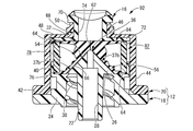
- FIG. 1 is a longitudinal sectional view of a needleless connector as a first embodiment of the present invention.
- II-II sectional drawing of FIG. The perspective view of the base housing which comprises the needleless connector shown by FIG.
- the perspective view of the elastic valve body which comprises the needleless connector shown by FIG. The front view of the elastic valve body shown by FIG.
- Explanatory drawing which shows the insertion state of the male luer in the needleless connector shown by FIG.
- the longitudinal cross-sectional view of the needleless connector as the 2nd Embodiment of this invention.
- XI-XI sectional drawing of FIG. The perspective view of the elastic valve body which comprises the needleless connector shown by FIG.
- FIGS. 1 and 2 show a needleless connector 10 as a first embodiment of the present invention.
- the needleless connector 10 has a structure in which a lower valve 14 as an elastic valve body and an upper valve 16 as a second valve body are incorporated in a housing 12.
- the vertical direction refers to the vertical direction in FIGS.
- the housing 12 has a divided structure, and includes a base housing 18 on the base end side that is the lower side in FIG. 1 and a cover housing 20 on the front end side that is the upper side in FIG. .
- the base housing 18 is provided with a peripheral wall portion 24 apart from the outer peripheral side of the cylindrical portion 22 extending on the central axis, and the upper bottom portion 26 integrally connects between the cylindrical portion 22 and the upper end portion of the peripheral wall portion 24. It is connected. Further, the cylindrical portion 22 protrudes downward from the peripheral wall portion 24, and a chemical liquid channel 28 is formed inside the cylindrical portion 22. On the other hand, a lock groove 30 is formed on the inner peripheral surface of the peripheral wall portion 24.
- an intravascular indwelling catheter (not shown) is connected to the proximal end opening of the cylindrical portion 22 of the base housing 18.
- the cylindrical portion 22 and the peripheral wall portion 24 constitute a lock-type luer structure, so that the catheter can be reliably connected.
- a projecting support surface 32 is formed.
- a top portion 34 extending in the shape of a ridge line is formed at least at the tip portion (upward in FIG. 3) of the projecting support surface 32.
- the projecting support surface 32 has a long mountain shape as a whole.
- the chemical liquid channel 28 formed in the cylindrical portion 22 is opened at the upper tip portion, and is a nozzle-like tip opening portion 36 having a reduced cross-sectional area.
- the nozzle-like tip opening 36 opens at the center of the top 34 extending in a ridgeline shape on the projecting support surface 32.
- the projecting support surface 32 is a taper-shaped taper having a hem extending at a substantially constant inclination angle from the top to the skirt. It is an inclined surface. That is, the projecting support surface 32 is not provided with a folding point or a bending point at an intermediate portion in the height direction, and is an inclined surface extending substantially linearly in the vertical direction.
- the inclined surface of the projecting support surface 32 is not limited to a straight line, and may be curved, and one or more folding points or bending points may be provided in the middle of the height direction. You may have.
- a linear communication groove 37 extending downward from the top 34 is formed on the projecting support surface 32.
- a pair of communication grooves 37a, 37a are formed in the left-right direction in FIG. 1
- a pair of communication grooves 37b, 37b are formed in the left-right direction in FIG.
- the pair of communication grooves 37 b and 37 b are linearly formed extending from the distal end opening 36 of the chemical liquid flow channel 28 that is the center of the top portion 34 to the lower end skirt of the projecting support surface 32.
- An annular flat surface 38 (see FIG. 3) is formed on the upper end surface of the base housing 18 so that the outer peripheral side of the protruding support surface 32 extends in the circumferential direction with a predetermined width, and the outer peripheral edge of the flat surface 38.
- An outer peripheral collar 40 that protrudes upward in a cylindrical shape is formed integrally with the part.
- a step 42 for positioning and fixing the cover housing 20 is formed on the outer peripheral surface of the base housing 18.
- the cover housing 20 constituting the housing 12 in cooperation with such a base housing 18 has a stepped cylindrical shape as a whole as shown in FIGS. That is, in the cover housing 20, the cover main body 44 having a large-diameter cylindrical shape and the connection port portion 46 having a small-diameter cylindrical shape are integrally connected by the upper bottom portion 48 having an annular plate shape.
- the cover body 44 that opens downward is assembled from above the base housing 18, and the opening of the cover body 44 is fitted to the outer peripheral surface of the base housing 18.
- the opening portion of the cover main body 44 is fixed to the base housing 18 by fixing means such as press-fitting, welding, and adhesion while being positioned in the axial direction by the step 42 of the base housing 18.
- the cover housing 20 is assembled to the base housing 18, so that an internal region whose periphery is covered with the cover housing 20 is formed above the base housing 18. Further, the internal region is opened upward through the connection port portion 46 of the cover housing 20.
- a lock groove 50 is formed on the outer peripheral surface of the connection port portion 46.
- an air vent hole 52 penetrating inward and outward is formed in each peripheral wall of the cover body 44 and the connection port portion 46.
- the lower valve 14 and the upper valve 16 are incorporated into the inner region formed in the housing 12 as described above.
- the lower valve 14 has a valve main body 54 as a thick wall portion having a block shape, and an expansion having an outer peripheral surface shape that extends in a tapered shape below the valve main body. And a diameter portion 56.
- the shape of the outer peripheral surface of the valve main body 54 is not particularly limited, but in the present embodiment, it is a substantially elliptic cylinder.
- each one valley part 58 and peak part 60 are each formed in the annular
- the valley portion 58 is formed on the outer peripheral surface of the upper end portion of the valve main body portion 54, while the peak portion 60 is formed on the outer peripheral surface of the lower end portion of the valve main body portion 54.
- the entire lower valve 14 is also formed at the boundary portion between the valve main body portion 54 and the enlarged diameter portion 56.
- a trough 58 extending around the circumference is formed.
- the unevenness formed on the outer peripheral surface of the lower valve 14 is formed by a smooth curve having no corners.
- the outer peripheral surfaces of the valve main body portion 54 and the enlarged diameter portion 56 are formed into a smooth curved cross-sectional shape having no break points as a whole including the valley portions 58 and 58 and the peak portion 60.
- valve main body portion 54 indicates a virtual outer peripheral surface shape in which the concave and convex valley portions 58 and the peak portions 60 are not formed in the valve main body portion 54. That is, the outer peripheral surface shape of the valve main body 54 shown by the phantom line is an elliptical cylindrical base shape.
- a slit 62 is formed in the central portion of the valve main body portion 54 so as to penetrate in the vertical direction.
- the valve body portion 54 has an elliptical outer cross-sectional shape, and the slit 62 extends in the major axis direction of the ellipse.
- a pair of flange portions 64 and 64 are integrally formed on the outer peripheral surfaces of the upper and lower ends of the valve main body portion 54 at both end portions of the slit 62 in the penetrating direction, and spread outwardly.
- the upper end surface of the lower valve 14 is a flat surface, while the lower end surface is formed with a recess 66 that opens to the center portion.
- the shape of the inner peripheral surface of the recess 66 is a tapered surface shape corresponding to the protruding support surface 32 of the base housing 18 described above.
- the recess 66 has an elliptical tapered surface that gradually expands toward the opening at the lower end.
- the inner peripheral surface of the recess 66 has substantially the same inclination angle as the outer peripheral surface of the enlarged diameter portion 56. And the recessed part 66 is formed in the inside of the enlarged diameter part 56, and the enlarged diameter part 56 is made into the thin part of a taper cylinder shape. Note that the upper portion of the recess 66 extends to an intermediate portion in the axial direction of the valve main body 54 constituting the thick portion.
- the upper valve 16 includes a valve main body 68 having a substantially flat elliptical cross-sectional shape and extending in the vertical direction.
- a pair of flange portions 70 and 72 are integrally formed on the surface.
- a slit 74 is formed in the central portion of the valve main body 68 so as to penetrate in the vertical direction. The slit 74 extends in the major axis direction of the flat ellipse in the cross section of the upper valve 16 and penetrates linearly in the vertical direction.
- the lower valve 14 and the upper valve 16 are incorporated in the housing 12 in a state where the upper valve 16 is superimposed on the upper end surface (outer end surface) of the lower valve 14.
- the lower valve 14 is assembled in a state in which the projecting support surface 32 of the base housing 18 is fitted into the recess 66, and the inner surface of the recess 66 is the projecting support surface 32.
- the substantially entire surface is overlaid in a substantially close contact state. That is, the inner peripheral surface of the enlarged diameter portion 56 constituting the thin wall portion of the lower valve 14 is superimposed on the skirt side region of the protruding support surface 32 of the base housing 18, and the top side of the protruding support surface 32. In the region, a valve main body 54 constituting a thick portion in the lower valve 14 is overlaid.
- the lower flange portion 64 of the lower valve 14 is overlapped with the flat surface 38 of the base housing 18 on the outer peripheral side of the projecting support surface 32 in a substantially close contact state.
- a lower flange portion 72 of the upper valve 16 is overlapped with the upper flange portion 64 of the lower valve 14, and both flange portions 64 and 72 having substantially the same outer diameter are formed on the cover housing 20. It is superimposed on the lower surface of the upper bottom 48.
- a cylindrical holding sleeve 76 is incorporated in the housing 12 and is arranged in an extrapolated state on the valve body 54 of the lower valve 14.
- the pressing sleeve 76 is assembled between the upper and lower flange portions 64 and 64 of the lower valve 14 in a state where the lower end portion is fitted into the outer peripheral collar 40 of the base housing 18 and positioned.
- the height dimension (vertical direction in FIG. 1) of the pressing sleeve 76 is slightly larger than the distance between the opposing surfaces of the pair of upper and lower flange portions 64 and 64 of the lower valve 14.
- the outer peripheral portion of the lower flange portion 64 of the lower valve 14 is pressed against the flat surface 38 of the base housing 18 by the lower end surface in the axial direction of the pressing sleeve 76 and is fixed in a sealed manner.
- the outer peripheral portions of the upper flange portion 64 of the lower valve 14 and the lower flange portion 72 of the upper valve 16 that are overlapped with each other by the upper end surface in the axial direction of the pressing sleeve 76 are the upper bottom portion 48 of the cover housing 20. The seal is fixed by being pressed.
- the outer peripheral side of the valve main body 54 is deformed as an internal space that allows elastic deformation of the lower valve 14 toward the outer peripheral side.
- An allowable space 78 is formed.
- the pressing sleeve 76 is spaced outward from the outer peripheral surface of the valve main body 54 of the lower valve 14, and between the valve main body 54 and the pressing sleeve 76, that is, the lower valve 14.
- a deformation allowing space 78 is formed between the opposing surfaces of the pair of upper and lower flange portions 64, 64.
- the pressing sleeve 76 has one or a plurality of radial through holes 80 (two in the present embodiment) and a gap between the pressing sleeve 76 and the cover main body 44 of the cover housing 20. 82 is formed. Thus, a space communication path that connects the deformation allowing space 78 to the external space is formed by the through hole 80, the gap 82, and the air vent hole 52.
- the upper valve 16 has a valve main body 68 disposed in the connection port portion 46 of the cover housing 20, and an upper flange portion 70 of the upper valve 16 is superimposed on the upper opening end surface of the connection port portion 46. Yes.
- the elastic deformation of the valve main body 68 is permitted in a direction orthogonal to the direction in which the slit 74 extends (left and right direction in FIG. 1).
- a deformation allowable space 84 is formed.
- the lower valve 14 is aligned in the circumferential direction with respect to the base housing 18 so that the major axis direction of the valve main body 54 extends in the ridge line direction of the apex 34 that is formed into a long mountain shape on the projecting support surface 32. ing.
- the slit 62 as the valve hole of the lower valve 14 extends along the ridge-shaped top 34 of the projecting support surface 32 of the base housing 18.
- the slit 62 is in close contact before the male luer 88 described later is inserted, and is not open.
- the distal end opening 36 of the chemical liquid flow path 28 of the cylindrical portion 22 opens at the center of the top portion 34 that extends in a ridgeline shape on the protruding support surface 32. .
- the slit 74 as the valve hole of the upper valve 16 is positioned and assembled in the circumferential direction in a state extending in a direction substantially orthogonal to the slit 62 of the lower valve 14.
- the distal end opening 36 of the chemical flow path 28 of the base housing 18 is positioned on the central axis extending in the vertical direction through the intersection of the slit 62 of the lower valve 14 and the slit 74 of the upper valve 16. Yes.
- the needleless connector 10 having the above-described structure is used with an intravascular indwelling catheter or the like (not shown) connected to the proximal end opening of the drug solution flow path 28 as described above.
- the male luer 88 such as the syringe 86 enters the slits 74 and 62 of the upper valve 16 and the lower valve 14 through the connection port portion 46 of the housing 12 from above as shown in FIG. 9.
- the respective slits 74 and 62 are expanded, and the male luer 88 is brought into communication with the chemical liquid flow path 28.
- the male luer 88 of the syringe 86 shown in FIG. 9 has a male luer lock structure so that the connection state with respect to the connection port portion 46 of the housing 12 is reliably maintained.
- the male luer 88 may have not only a luer lock structure that is fixed with screws, but also a luer slip structure that is inserted and fixed.
- the pushing force of the male luer 88 is applied to the lower valve 14, and the central portion of the valve main body 54 of the lower valve 14 is pushed downward. It is done. Along with this depression, the lower surface of the valve main body 54 is deformed so as to be spread on both sides of the slit 62 along the protruding support surface 32 brought into a close contact state. At that time, in the lower valve 14, the elasticity is partially changed by the valley portion 58 and the peak portion 60 formed on the outer peripheral surface. Therefore, when the lower valve 14 is deformed along the projecting support surface 32 when the male luer 88 is inserted, the lower valve 14 is easily deformed by being bent by the valley portion 58.
- the deformation rigidity of the lower valve 14 when the male luer 88 is inserted is reduced, and the male luer 88 can be easily inserted.
- the curve near the valley portion 58 that is easily deformed and the shape retention near the mountain portion 60 that is difficult to deform cooperate with each other outward from the projecting support surface 32.
- the gap 90 is reliably and stably generated with a large volume between the lower valve 14 bent and deformed so as to be separated from the protruding support surface 32.
- the circumferentially extending gap 90 is formed by the pair of communication holes 37a and 37a and the pair of communication holes 37b and 37b formed on the projecting support surface 32.
- the slit 62 communicates more reliably and stably.
- the inclined surface forming the projecting support surface 32 is linear in the cross section in the vertical direction, and has no fold points or bending points. Therefore, it is easy to more stably realize the close contact between the protruding support surface 32 and the recess 66 of the lower valve 14, and before the male luer 88 is inserted and after the male luer 88 is extracted, A gap or the like based on a manufacturing error or the like hardly occurs between the recess 66 and the like. Accordingly, a gap 90 that is not formed before the male luer 88 is inserted between the protruding support surface 32 and the recess 66 can be reliably formed when the male luer 88 is inserted. Furthermore, when the male luer 88 is extracted, a positive pressure associated with the volume reduction can be generated with certainty.
- the gap 90 between the projecting support surface 32 and the recess 66 when the male luer 88 is inserted is changed by changing the number and shape of the valley portions 58 and the mountain portions 60 formed on the outer peripheral surface of the lower valve 14. It is also possible to adjust the shape and size. That is, by adjusting the position, number, size, shape, and the like of the valley portion 58 and the mountain portion 60, the elastic deformation rigidity and elastic deformation mode of the lower valve 14 when the male luer 88 is inserted, the size of the gap 90, and the like. It is possible to adjust the insertion resistance of the male luer 88 and the magnitude of the positive pressure when the male luer 88 is withdrawn.
- the deformation allowing space 78 formed on the outer periphery of the lower valve 14 communicates with the external space through the through hole 80, the gap 82, and the air vent hole 52.
- the elastic deformation and the effect based thereon are not hindered by the action of the air spring in the deformation permissible space 78 and can be exhibited more advantageously.
- the external communication path is not essential in the present invention, and the deformation permissible space 78 can be a sealed structure.
- FIGS. 10 and 11 show a needleless connector 92 according to a second embodiment of the present invention.
- the same members and parts as those of the first embodiment are denoted by the same reference numerals as those of the first embodiment in the drawings, and detailed description thereof is omitted.
- the shape of the lower valve 94 constituting the needleless connector 92 is different from that of the lower valve 14 of the first embodiment.
- FIGS. 12 to 16 show the lower valve 94 of the present embodiment. ing.
- a male luer 88 such as a syringe 86 is connected from the connection port portion 46 of the housing 12.
- the slits 62 and 74 of the lower valve 94 and the upper valve 16 are expanded, and the male luer 88 is brought into communication with the chemical flow path 28.
- the lower valve 94 is the same as in the first embodiment.
- the gap 90 is stably formed with a large volume between the recess 66 and the projecting support surface 32. As a result, the insertion operation of the male luer 88 is facilitated, and the effect of preventing the backflow of blood or the like when the male luer 88 is withdrawn is sufficiently exhibited.
- the enlarged diameter portion 56 is also provided with a valley portion 58 and a ridge portion 60 in which irregularities are formed on the outer peripheral surface. Therefore, the elastic deformation mode of the lower valve 94 when the male luer 88 is inserted can be set to a desired shape over the entire valve main body portion 54 and the enlarged diameter portion 56. Therefore, the effect of preventing the backflow of blood or the like when the male luer 88 is extracted can be set with a greater degree of freedom.
- Example 1 A needleless connector having a structure according to the first embodiment and the second embodiment was made as an experiment, and an experiment was conducted to confirm the effect of preventing blood backflow. The experimental results are shown below as Example 1 and Example 2.
- a lower valve 96 having the shape shown in FIGS. 18 and 19 was prepared, and the needleless connector 10 of Example 1 was prepared by assembling the lower valve 96 in place of the lower valve 14. .
- attached this lower valve 96 the result of having conducted the experiment similar to Example 1, 2 is shown collectively as a comparative example below.
- the lower valve 96 as a comparative example is one in which the valve main body 54 of the lower valve 14 in the first embodiment has a base-shaped outer peripheral surface indicated by an imaginary line in FIGS. The shape and dimensions of the other parts are the same as those of the lower valve 14 of the first embodiment.
- the needleless connector of Example 1 having the structure according to the first embodiment, at the time of withdrawal of the syringe, retraction is not recognized once, and discharge is confirmed in all measurements. It was in the range of 8-20 ⁇ L. Further, in the needleless connector of Example 2, the withdrawal was not recognized once when the syringe was pulled out, and the discharge was confirmed in all the measurements, and the discharge amount was in the range of 1 to 3 ⁇ L. On the other hand, in the needleless connector of the comparative example, the pull-in was observed when the syringe was pulled out.
- the needleless connector having the structure according to the present invention can exert the effect of preventing blood backflow when the syringe is pulled out as compared with the needleless connector of the comparative example.
- the shape and size of the valleys and peaks provided on the outer peripheral surface of the lower valve it is recognized that the amount of blood discharged as a result of extraction and thus the effect of preventing blood backflow can be set appropriately.
- the separate upper valve 16 is superimposed on the lower valve 14 (94), and the slits 62 and 74 are aligned perpendicularly to each other in the circumferential direction.
- the slit 62 of the lower valve 14 (94) is closed, so that infusion and blood leaks when the male luer 88 is inserted and removed. It is possible to prevent the ejection more effectively.
- the slits 74 and 62 of the upper valve 16 and the lower valve 14 (94) are arranged orthogonally, and only the lower valve 14 (94) is employed without using the upper valve 16. Is also possible.
- the upper valve 16 and the lower valve 14 (94) may be integrated.
- the valve shape in that case may not be the shape which combined the upper valve 16 and the lower valve 14 of FIG. 1, for example, and it is good also as a valve shape in which the flange part 64 was formed only in the lower part of the valve. In this way, if the valve shape does not include a flange portion in the valve intermediate portion, a portion for positioning the flange of the valve intermediate portion is unnecessary, and the diameter of the center portion of the needleless connector 10 (92) can be reduced. .
- the inclined surface shape of the protruding support surface 32 is linear in the vertical cross section.
- the break point is formed on the inclined surface of the protruding support surface 32.
- a bending point may be provided, and the inclination angle may be partially different.
- the shape of the recess 66 of the lower valve 14 (94) is made to correspond to the shape of the projecting support surface 32, and the projecting support surface 32 and the inner peripheral surface of the recess 66 are completely brought into close contact with each other.
- the protruding support surface 32 and the inner peripheral surface of the recess 66 may be slightly separated from each other.
- the shape of the top portion 34 is not limited to the long mountain shape, and may be, for example, a circular shape or a polygonal shape.
- the trough part 58 and the peak part 60 were provided in the valve main-body part 54, it is not necessarily limited to this,
- the trough part 58 and the peak part 60 are only the enlarged diameter part 56. May be provided.
- the entire lower valve 14 (94) is formed into a base shape extending in the axial direction with a constant outer peripheral surface shape, and the outer peripheral surface is uneven.
- the valley portion 58 and the mountain portion 60 may be formed as appropriate.
- valley portion 58 and the mountain portion 60 do not have to be continuous over the entire circumference of the lower valve 14 (94), and an appropriate number of valley portions 58 and peak portions 60 are partially provided in the circumferential direction on the outer peripheral surface of the lower valve 14 (94). May be formed. Furthermore, the valley part 58 and the peak part 60 may be formed separately in the axial direction of the lower valve 14 (94).
- the deformation allowing space 78 for allowing elastic deformation of the lower valve 14 (94) is provided, but the shape is not necessarily limited to the shape of the embodiment. Furthermore, the holding sleeve 76 and the outer collar 40 are not necessarily required. Therefore, for example, the lower valve may have a shape extending over the entire inner peripheral surface of the region formed by the base housing 18 and the cover main body 44. In this case, the lower valve is disposed inside the lower valve. A hermetically sealed deformation-permitting space that allows elastic deformation may be provided.
- the deformation allowable space 78, the through hole 80, and the gap 82 of the lower valve 14 (94) in the above embodiment may be filled with a synthetic foam having sponge-like open cells such as polyurethane.
- a synthetic foam has a substantial space of open cells inside, is excellent in flexibility and elasticity, and is extensible. Therefore, when the male luer 88 is inserted, the lower valve 14 is compressed by deformation.
- the elastic foam of (94) is allowed, and the shape of the synthetic foam can be changed in accordance with the shape of the lower valve 14 (94) after the deformation.
- a substantial space is provided by disposing a compressible and elastic member such as a synthetic foam. Also good.
- the pair of communication grooves 37a and 37a and the pair of communication grooves 37b and 37b are provided on the protruding support surface 32.
- these communication grooves 37 are not necessarily required.
- the number, direction, shape, and the like of the communication grooves to be formed are not limited at all. For example, five or more communication grooves may be formed on the projecting support surface 32 or may be curved.
Landscapes
- Health & Medical Sciences (AREA)
- Heart & Thoracic Surgery (AREA)
- Pulmonology (AREA)
- Engineering & Computer Science (AREA)
- Anesthesiology (AREA)
- Biomedical Technology (AREA)
- Hematology (AREA)
- Life Sciences & Earth Sciences (AREA)
- Animal Behavior & Ethology (AREA)
- General Health & Medical Sciences (AREA)
- Public Health (AREA)
- Veterinary Medicine (AREA)
- Infusion, Injection, And Reservoir Apparatuses (AREA)
Abstract
L'invention concerne un nouveau raccord sans aiguille, qui peut empêcher un refoulement de sang ou analogue au moyen d'une structure simple. Dans le raccord sans aiguille (10), qui est tel qu'un corps de valve élastique (14) est incorporé à l'intérieur d'un boîtier (12), sur lequel a été formé un conduit de médicament (28), et lorsqu'un raccord Luer mâle (88) est introduit dans une fente (62) du corps de valve élastique (14), le corps de valve élastique (14) s'ouvre et le raccord Luer mâle (88) est relié au conduit de médicament (28), une surface de support saillante (32) ayant une surface inclinée évasée est formée sur le boîtier (12), le corps de valve élastique (14) est superposé sur la surface de support saillante (32) dans l'état de contact étroit avec celle-ci et, au niveau de la surface de support saillante (32), la fente (62) du corps de valve élastique (14) est positionnée sur l'ouverture (36) du conduit de médicament (28) et des ondulations sont conférées à la surface périphérique externe du corps de valve élastique (14) superposé sur la surface de support saillante (32), formant des montagnes (60) et des vallées (58) s'étendant dans la direction périphérique.
Priority Applications (1)
| Application Number | Priority Date | Filing Date | Title |
|---|---|---|---|
| JP2014538591A JP6311934B2 (ja) | 2012-09-26 | 2013-09-26 | ニードルレスコネクター |
Applications Claiming Priority (2)
| Application Number | Priority Date | Filing Date | Title |
|---|---|---|---|
| JP2012-213139 | 2012-09-26 | ||
| JP2012213139 | 2012-09-26 |
Publications (1)
| Publication Number | Publication Date |
|---|---|
| WO2014050976A1 true WO2014050976A1 (fr) | 2014-04-03 |
Family
ID=50388371
Family Applications (1)
| Application Number | Title | Priority Date | Filing Date |
|---|---|---|---|
| PCT/JP2013/076084 Ceased WO2014050976A1 (fr) | 2012-09-26 | 2013-09-26 | Raccord sans aiguille |
Country Status (2)
| Country | Link |
|---|---|
| JP (1) | JP6311934B2 (fr) |
| WO (1) | WO2014050976A1 (fr) |
Cited By (2)
| Publication number | Priority date | Publication date | Assignee | Title |
|---|---|---|---|---|
| JP2016106957A (ja) * | 2014-12-09 | 2016-06-20 | ニプロ株式会社 | ニードルレスコネクター |
| JP2017144184A (ja) * | 2016-02-19 | 2017-08-24 | 株式会社ジェイ・エム・エス | アダプタ |
Citations (4)
| Publication number | Priority date | Publication date | Assignee | Title |
|---|---|---|---|---|
| US6050978A (en) * | 1997-05-09 | 2000-04-18 | Becton Dickinson And Company | Needleless valve connector |
| WO2009133754A1 (fr) * | 2008-05-02 | 2009-11-05 | テルモ株式会社 | Ensemble connecteur |
| JP2010508986A (ja) * | 2006-11-02 | 2010-03-25 | ベクトン・ディキンソン・アンド・カンパニー | 血管アクセス装置のチャンバ通気 |
| JP2010514528A (ja) * | 2007-01-03 | 2010-05-06 | ヴィゴン | 特に医療分野用の弁制御流体連通を確立するためのコネクタ |
Family Cites Families (2)
| Publication number | Priority date | Publication date | Assignee | Title |
|---|---|---|---|---|
| NZ286445A (en) * | 1995-05-16 | 1997-12-19 | Ivac Corp | Needleless luer connector: deformable piston occludes bore |
| US8758306B2 (en) * | 2010-05-17 | 2014-06-24 | Icu Medical, Inc. | Medical connectors and methods of use |
-
2013
- 2013-09-26 WO PCT/JP2013/076084 patent/WO2014050976A1/fr not_active Ceased
- 2013-09-26 JP JP2014538591A patent/JP6311934B2/ja active Active
Patent Citations (4)
| Publication number | Priority date | Publication date | Assignee | Title |
|---|---|---|---|---|
| US6050978A (en) * | 1997-05-09 | 2000-04-18 | Becton Dickinson And Company | Needleless valve connector |
| JP2010508986A (ja) * | 2006-11-02 | 2010-03-25 | ベクトン・ディキンソン・アンド・カンパニー | 血管アクセス装置のチャンバ通気 |
| JP2010514528A (ja) * | 2007-01-03 | 2010-05-06 | ヴィゴン | 特に医療分野用の弁制御流体連通を確立するためのコネクタ |
| WO2009133754A1 (fr) * | 2008-05-02 | 2009-11-05 | テルモ株式会社 | Ensemble connecteur |
Cited By (4)
| Publication number | Priority date | Publication date | Assignee | Title |
|---|---|---|---|---|
| JP2016106957A (ja) * | 2014-12-09 | 2016-06-20 | ニプロ株式会社 | ニードルレスコネクター |
| JP2017144184A (ja) * | 2016-02-19 | 2017-08-24 | 株式会社ジェイ・エム・エス | アダプタ |
| WO2017141858A1 (fr) * | 2016-02-19 | 2017-08-24 | 株式会社ジェイ・エム・エス | Adaptateur |
| CN108472478A (zh) * | 2016-02-19 | 2018-08-31 | 株式会社Jms | 适配器 |
Also Published As
| Publication number | Publication date |
|---|---|
| JP6311934B2 (ja) | 2018-04-18 |
| JPWO2014050976A1 (ja) | 2016-08-22 |
Similar Documents
| Publication | Publication Date | Title |
|---|---|---|
| JP6150139B2 (ja) | ニードルレスコネクター | |
| US12377227B2 (en) | Hemostasis valve-equipped indwelling needle and indwelling needle assembly | |
| US8100868B2 (en) | Anti-drawback medical valve | |
| EP3756723B1 (fr) | Vanne femelle sans reflux à petit volume d'amorçage | |
| JP6925319B2 (ja) | バルブを備えたカテーテル装置および関連方法 | |
| CN101152594A (zh) | 用于医疗管线的阀连接器 | |
| JP2022512170A (ja) | 血液管理システムを備えたカテーテル装置及び関連する方法 | |
| US12350464B2 (en) | Needleless connector having check valve with lip seal | |
| JP6311934B2 (ja) | ニードルレスコネクター | |
| JP6029086B2 (ja) | 弁付カテーテル | |
| JP2016106958A (ja) | ニードルレスコネクター | |
| JP2023542872A (ja) | バルブピボットサポートを備えた逆止バルブを有するニードルレスコネクター | |
| JP2020142019A (ja) | 弁付き針組立体 | |
| JP6489352B2 (ja) | ニードルレスコネクター | |
| JP2017104233A (ja) | ニードルレスコネクター | |
| JPWO2020091055A1 (ja) | 留置針組立体および医療用弁 |
Legal Events
| Date | Code | Title | Description |
|---|---|---|---|
| 121 | Ep: the epo has been informed by wipo that ep was designated in this application |
Ref document number: 13840607 Country of ref document: EP Kind code of ref document: A1 |
|
| ENP | Entry into the national phase |
Ref document number: 2014538591 Country of ref document: JP Kind code of ref document: A |
|
| NENP | Non-entry into the national phase |
Ref country code: DE |
|
| 122 | Ep: pct application non-entry in european phase |
Ref document number: 13840607 Country of ref document: EP Kind code of ref document: A1 |