WO2014064773A1 - 豚屠体腕部位の左右判別システム - Google Patents
豚屠体腕部位の左右判別システム Download PDFInfo
- Publication number
- WO2014064773A1 WO2014064773A1 PCT/JP2012/077376 JP2012077376W WO2014064773A1 WO 2014064773 A1 WO2014064773 A1 WO 2014064773A1 JP 2012077376 W JP2012077376 W JP 2012077376W WO 2014064773 A1 WO2014064773 A1 WO 2014064773A1
- Authority
- WO
- WIPO (PCT)
- Prior art keywords
- arm part
- discriminating
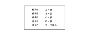
- discrimination
- deboning
- workpiece
- Prior art date
- Legal status (The legal status is an assumption and is not a legal conclusion. Google has not performed a legal analysis and makes no representation as to the accuracy of the status listed.)
- Ceased
Links
Images




Classifications
-
- A—HUMAN NECESSITIES
- A22—BUTCHERING; MEAT TREATMENT; PROCESSING POULTRY OR FISH
- A22B—SLAUGHTERING
- A22B7/00—Slaughterhouse arrangements
- A22B7/001—Conveying arrangements
- A22B7/003—Positioning, orienting or supporting carcasses as they are being conveyed
-
- A—HUMAN NECESSITIES
- A22—BUTCHERING; MEAT TREATMENT; PROCESSING POULTRY OR FISH
- A22C—PROCESSING MEAT, POULTRY, OR FISH
- A22C17/00—Other devices for processing meat or bones
- A22C17/0073—Other devices for processing meat or bones using visual recognition, X-rays, ultrasounds, or other contactless means to determine quality or size of portioned meat
-
- G—PHYSICS
- G01—MEASURING; TESTING
- G01N—INVESTIGATING OR ANALYSING MATERIALS BY DETERMINING THEIR CHEMICAL OR PHYSICAL PROPERTIES
- G01N21/00—Investigating or analysing materials by the use of optical means, i.e. using sub-millimetre waves, infrared, visible or ultraviolet light
- G01N21/17—Systems in which incident light is modified in accordance with the properties of the material investigated
- G01N21/25—Colour; Spectral properties, i.e. comparison of effect of material on the light at two or more different wavelengths or wavelength bands
- G01N21/251—Colorimeters; Construction thereof
-
- G—PHYSICS
- G01—MEASURING; TESTING
- G01N—INVESTIGATING OR ANALYSING MATERIALS BY DETERMINING THEIR CHEMICAL OR PHYSICAL PROPERTIES
- G01N21/00—Investigating or analysing materials by the use of optical means, i.e. using sub-millimetre waves, infrared, visible or ultraviolet light
- G01N21/17—Systems in which incident light is modified in accordance with the properties of the material investigated
- G01N21/25—Colour; Spectral properties, i.e. comparison of effect of material on the light at two or more different wavelengths or wavelength bands
- G01N21/27—Colour; Spectral properties, i.e. comparison of effect of material on the light at two or more different wavelengths or wavelength bands using photo-electric detection ; circuits for computing concentration
-
- G—PHYSICS
- G01—MEASURING; TESTING
- G01N—INVESTIGATING OR ANALYSING MATERIALS BY DETERMINING THEIR CHEMICAL OR PHYSICAL PROPERTIES
- G01N23/00—Investigating or analysing materials by the use of wave or particle radiation, e.g. X-rays or neutrons, not covered by groups G01N3/00 – G01N17/00, G01N21/00 or G01N22/00
- G01N23/02—Investigating or analysing materials by the use of wave or particle radiation, e.g. X-rays or neutrons, not covered by groups G01N3/00 – G01N17/00, G01N21/00 or G01N22/00 by transmitting the radiation through the material
- G01N23/04—Investigating or analysing materials by the use of wave or particle radiation, e.g. X-rays or neutrons, not covered by groups G01N3/00 – G01N17/00, G01N21/00 or G01N22/00 by transmitting the radiation through the material and forming images of the material
-
- G—PHYSICS
- G01—MEASURING; TESTING
- G01N—INVESTIGATING OR ANALYSING MATERIALS BY DETERMINING THEIR CHEMICAL OR PHYSICAL PROPERTIES
- G01N2201/00—Features of devices classified in G01N21/00
- G01N2201/12—Circuits of general importance; Signal processing
Definitions
- the present invention relates to a right and left discrimination system for a pig carcass arm part that is suitable for application to a deboning device for a pig carcass arm part.
- Patent Document 1 discloses a deboning processing technique for a thigh region of a livestock carcass.
- Patent Document 1 discloses a left and right thigh region discrimination method performed at a stage before deboning processing. This right / left discrimination method focuses on the fact that the position of the bottom depression formed after removing the hipbone differs between the left and right thigh parts, compared to the thigh part after removing the hipbone in the pre-processing. By detecting the position of the dent with the sensing plate, the left and right are discriminated.
- the left / right discrimination method disclosed in Patent Document 1 is a discrimination method using the shape of the thigh region, and is not suitable for application to the left / right discrimination of the arm region. Further, from the viewpoint of improving the efficiency of the deboning process, it is desirable to be able to distinguish left and right while the arm part is suspended by a clamper.
- the present invention makes it possible to discriminate between left and right while hanging on a clamper in a previous process of deboning process when deboning a pork carcass arm part widely used as meat.
- the purpose is to improve the deboning efficiency.
- the system for discriminating left and right of a pig carcass arm part has a slit that is open in the horizontal direction and into which the wrist of the pig carcass is removably inserted.
- a clamp that is movable along the track with the arm part suspended, a light source that emits white visible light to the arm part suspended by the clamp, and a horizontal direction in which the slit opens.
- a color imaging device that captures an arm region irradiated with white visible light from an oblique horizontal direction, and a left / right determination device that performs left / right determination of the arm region based on image data of the arm region captured by the color imaging device; It has.
- white visible light means visible light that is not separated into visible rays having different wavelengths and colors.
- the arm part of the pig carcass is hung at random on the clamp tool without distinction between right and left.
- the present inventors have found a phenomenon in which the arm part suspended from the clamp device via the wrist part naturally rotates in different directions between the left and right arm parts.
- the present invention utilizes this phenomenon and arranges a color imaging device at a position where different imaging areas can be obtained in the left and right arm parts by the natural rotation of the left and right arm parts in different directions. Is possible.
- the left and right discriminating device includes an output extraction unit that extracts a red image signal corresponding to a red wavelength region from the imaged image data of an arm part of a pig carcass, and a red image signal extracted by the output extraction unit.
- a first binarization unit that performs binarization processing; and a left / right determination unit that performs left / right determination of the arm portion based on the red image signal binarized by the first binarization unit.
- the red image signal is, for example, an R (red) image signal in the RGB color system, and an M (magenta) image signal or a Y (yellow) image signal in the CMY color system.
- the output extraction unit divides an image captured by the color imaging apparatus into image signals of three primary colors of R (red), G (green), and B (blue), or C (cyan), M (magenta), and Y (
- the red image signal can be extracted by a method such as dividing into yellow).
- red image signals such as a G image signal, a B image signal, and a C image signal
- the meat part red part and fat part
- image data including a red image signal is included. Is used.
- the red color image signal is included, it is possible to determine the right and left even if other color system image data is included.
- This left / right discriminating device can accurately discriminate the left / right of the arm part. According to the present invention, it is possible to accurately discriminate left and right while suspending the arm part of the pig carcass from the clamp tool, so that the processing efficiency of the deboning device can be improved.
- the opening of the slit of the clamp tool is directed in a direction orthogonal to the trajectory, and an oblique horizontal direction in which the color imaging device performs imaging is 15 ° to 55 ° with respect to the trajectory.
- the angle should be good.
- the direction of the cross-sectional shape of the wrist part differs between the left and right arm parts.
- the present invention suspends an arm part via a wrist part on a clamp having a slit opening in a direction perpendicular to the linear track in plan view, the direction is opposite to the track in plan view. It has been found that it rotates naturally within the range of [35 ⁇ 20] °. For this reason, by imaging the arm part of the pig carcass with the color imaging device arranged in the angle range, it is possible to obtain images with clearly different imaging areas at the left and right arm parts.
- the output extraction unit is capable of extracting a non-red image signal corresponding to a wavelength range other than the red wavelength range from the captured image data, and the left / right discrimination device is extracted by the output extraction unit.
- a second binarization unit that binarizes the non-red image signal and the distribution of the non-red image signal binarized by the second binarization unit. It is good to further have a front / back discriminating section for discriminating whether the front side of the part is facing or the back side is facing.
- the non-red system image signal is, for example, a G image signal or a B image signal in the RGB color system, and a C image signal in the CMY color system.
- the arm part of the pig carcass is the back part where the meat part is exposed on the base side with the shoulder part, and the front part where the meat part is not exposed is the part opposite to the back part.
- the red-outside image signal output from the output division portion is clearly less than that in the front side portion.
- the image output from the second binarization unit a region where there are many red image signals is enlarged.
- the skin remains attached to the front side portion and a case where the skin is removed depending on the pretreatment method of the deboning process.
- the skin is removed, the fat under the skin is exposed and the fat is white, so the red external image signal of the front side part is almost the same image regardless of the presence or absence of the skin Signal. Therefore, the front side portion and the back side portion can be distinguished regardless of the presence or absence of the skin, and accurate front / back discrimination becomes possible.
- the left / right discriminating unit and the front / back discriminating unit the left / right discriminating of the arm part and the front / back discriminating can be performed simultaneously.
- the left and right discrimination of the arm part and the orientation of the arm part can be accurately grasped, so that accurate placement can be performed in a subsequent process. Therefore, it is possible to perform the deboning process with a good yield of the meat part.
- a suspending device that suspends an arm part from a clamp tool upstream of a position where photographing by a color imaging device is performed, and a detector that detects that the arm part is suspended from the clamp tool
- the imaging of the arm part by the color imaging device can be started in accordance with the time when the arm part is suspended from the clamp tool, and the right / left discrimination process can be started quickly with good timing.
- an X-ray imaging apparatus that obtains an X-ray image by irradiating an X-ray to an arm part downstream of a position where imaging by a color imaging apparatus is performed, and a position where X is captured by a color imaging apparatus and X
- the target value of the rotation angle based on the result of the left and right discrimination of the arm part by the clamp tool rotating device that rotates the clamp tool around the vertical axis and the position where the imaging is performed by the line imaging device
- a second control device for driving the clamp tool rotating device so that the clamp tool rotates by the set target value.
- the natural rotation angle of the arm part is grasped in advance, and by setting the natural rotation angle as a target value, the arm part tilted with respect to the trajectory by natural rotation is directly opposed to the X-ray irradiation direction.
- “facing the arm part directly to the X-ray irradiation direction of the X-ray imaging apparatus” means that the long side of the arm part is oriented in a direction substantially perpendicular to the X-ray irradiation direction and deboning in a post-process. It means that either the front side part or the back side part that can be processed is directed to the X-ray irradiation side.
- the X-rays do not pass through the arm part and a clear transmission image cannot be obtained.
- the deboning process cannot be performed unless a predetermined part of the front part or the inner part is directed to the X-ray irradiation side.
- the second control device sets a target value of the rotation angle based on the left / right discrimination result and the front / back discrimination result by the left / right discrimination device, and drives the clamp tool rotating device so that the clamp tool rotates by the set target value. It is good to be. In this manner, by rotating the clamp tool in consideration of the front / back discrimination result, the arm part can be accurately faced in the X-ray irradiation direction of the X-ray imaging apparatus.
- a correctness determination device that determines the correctness of the determination result by the left / right determination device from the direction of the clamp tool and the arm part reflected in the X-ray image obtained by the X-ray imaging device.
- the left and right arm portions after being suspended from the clamp tool are different in the direction of natural rotation with respect to the track of the clamp tool. For this reason, on the upstream side of the X-ray imaging apparatus, the direction in which the arm part is rotated to face the X-ray irradiation direction is also reversed between the left and right arm parts. Therefore, when the left / right determination device makes a right / left determination error, the arm part does not face the X-ray irradiation direction in the X-ray imaging device. The same applies when the front / back discrimination result is incorrect.
- the correctness of the right / left discrimination result and the front / back discrimination result can be confirmed from the direction of the clamp tool and the arm part reflected in the X-ray image obtained by the X-ray imaging apparatus. Therefore, the correctness of the left / right discrimination result and the front / back discrimination result can be automatically determined by performing image processing on the X-ray image by the correct / error discriminating apparatus and obtaining the orientation of the clamp tool and the arm part. An arm part that has been misidentified cannot obtain an X-ray image necessary for the deboning process, and thus is not subjected to the deboning process.
- the present invention it is possible to accurately discriminate right and left while suspending the arm part of the pig carcass from the clamp, so that when applied to a deboning device, the deboning processing efficiency can be improved.
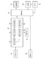
- FIG. 1 is a configuration diagram of a deboning apparatus to which the present invention is applied according to an embodiment of the present invention. It is a figure for demonstrating a pig's arm site
- FIG. 1 is a configuration diagram schematically showing a part of the deboning apparatus 10.
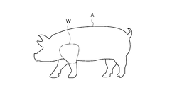
- the pig carcass arm part (hereinafter also referred to as “work”, which is denoted by the symbol W) to be deboned by the deboning apparatus 10 is composed of an arm part separated from the pork trunk A, as shown in FIG. It is meat with bone.
- the bone part of the workpiece W is composed of a forearm bone b1, a humerus b2, and a scapula b3 that form a wrist part Wf.
- the preprocessing station ST1 is provided with a conveyor for transporting the workpiece W, and the workpiece W is cut off at the tip side from the wrist portion Wf on the conveyor, leaving the wrist portion Wf.
- the deboning device 10 has an endless track 14 constituted by a chain spanned between two sprockets 12 (one of the sprockets is not shown).
- a plurality of clampers 16 are attached to the chain at equal intervals, and the sprocket 12 rotates in the direction of the arrow, so that each clamper circulates an endless track 14.
- a suspension station ST2 is provided adjacent to the pretreatment station ST1. For example, a six-axis articulated arm is provided in the suspension station ST2.
- a gripping unit is provided at the tip of the articulated arm, and the wrist unit Wf of the workpiece W is gripped by the gripping unit and suspended from the clamper 16. The workpiece W is suspended so that the front side portion faces the outside of the endless track 14.
- the clamper 16 has a slit 16a for inserting the workpiece W.
- the slit 16a is automatically closed by a chuck (not shown) provided in the clamper 16 after the workpiece W is inserted.
- the slit 16a is directed in the direction outside the endless track 14 and in a direction orthogonal to the endless track 14 in plan view.
- a photoelectric sensor 18 is provided at the downstream end of the conveyor provided in the preprocessing station ST1, and the presence or absence of the workpiece W is detected by the photoelectric sensor 18.
- the control device 20 is configured by, for example, a computer including a central processing unit, a memory, an external storage device, an input device, and an output device.
- An encoder 19 is provided in contact with the endless track 14, and the encoder 19 detects the amount of movement of the endless track 14. The movement amount detected by the encoder 19 is sent to the control device 20.
- the detection signal of the photoelectric sensor 18 is sent to the control device 20, and the control device 20 drives the articulated arm based on the detection signal of the photoelectric sensor 18 and the movement amount of the clamper 16 detected by the encoder 19, and the timing is adjusted.
- the workpiece W is suspended from the clamper 16.
- a left arm part or a right arm part is suspended from the clamper 16 at random.
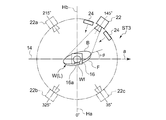
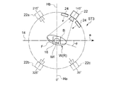
- FIG. 4A and 4B are diagrams schematically showing the left / right determination station ST3 in plan view.
- FIG. 4A shows a suspended state of the left workpiece W (L) that is the left arm portion of the pig carcass
- FIG. 4B shows a suspended state of the right workpiece W (R) that shows the right arm portion of the pig carcass.
- the workpiece W has a back side portion B where the meat portion of the base portion of the shoulder portion is exposed, and a front side portion F where the skin adheres to the surface or the skin is removed depending on the pretreatment method as described above. is there.
- the arrow a indicates the moving direction of the endless track 14.
- the left / right discrimination station ST3 is at a position that forms an angle of 145 ° (an angle of 35 ° with respect to the other orthogonal line Hb) with respect to one of the orthogonal lines Ha orthogonal to the endless track 14.
- a CCD camera 22 capable of color photography is provided.
- a plurality of photographing lights 24 that irradiate the work W with white visible light are provided around the CCD camera 22.
- the left work W (L) is naturally rotated by + ⁇ from the endless track 14 due to the shape of the wrist Wf after being suspended by the clamper 16 at the suspension station ST2.
- a clamper rotating device 26 is provided downstream of the moving direction of the endless track 14 with respect to the left / right discrimination station ST3, and an X-ray imaging station ST4 is provided downstream of the clamper rotating device 26.
- the X-ray imaging station ST4 includes an X-ray irradiation device 28, and the X-ray irradiation device 28 includes an X-ray source 30 and an X-ray filter 32. Further, the X-ray imaging station ST4 has a shielding box 34 that accommodates a workpiece W that is an imaging target of an X-ray image, and a line sensor 36 as an X-ray detector is installed in the shielding box 34. . An X-ray image of the workpiece W is taken at the X-ray imaging station ST4.
- the X-ray source 30 and the line sensor 34 are separated from each other in the horizontal direction perpendicular to the endless track 14 with the endless track 14 in between.
- the X-ray filter 32 gives an X-ray x intensity distribution so that a strong X-ray x is irradiated on a thick portion of the workpiece W and a weak X-ray is irradiated on a thin portion of the workpiece W.
- the X-ray image of the workpiece W imaged at the X-ray imaging station ST4 is image-analyzed by the control device 20, and the target coordinates on the bone part surface necessary for the post-scoring are determined.
- the irradiation direction of the X-ray x is orthogonal to the endless track 14.
- the clamper 16 that suspends the workpiece W is rotated around the vertical axis by the clamper rotating device 26 before reaching the X-ray imaging station ST4. That is, as shown in FIG. 5, based on the determination result at the left / right determination station ST3, the front side portion F of the workpiece W is directed to the side that irradiates the X-ray x, and the long side of the workpiece W is the endless track 14. Rotated to match.
- this posture is referred to as a posture facing the X-ray x.
- a round blade cutter 38 for placing a line around the wrist Wf is provided downstream of the endless track 14 in the moving direction with respect to the X-ray imaging station ST4.
- a first scoring station ST5 for scoring the workpiece W in the longitudinal direction is provided downstream of the round blade cutter 38.
- Another bracing station and a deboning station are provided downstream of the first bracing station ST5.
- the control device 20 controls these operations. Based on the target coordinates determined by X-ray imaging, the work W is subjected to a creasing and deboning process at these stations and separated into a bone part and a meat part. The separated bone part and meat part are separately discharged from the clamper 16.
- the emptied clamper 16 returns to the suspension station ST2, where the next workpiece W is suspended (details of this deboning device are described in the Japanese application; Japanese Patent Application No. 2012-56287, description and drawings) (Not disclosed at the time of filing an invention)).
- the control device 20 sends a trigger signal for starting imaging to the CCD camera 20 to start imaging (S10).
- the work W is irradiated with white visible light from the photographing light 24, and the CCD camera 20 photographs the work W based on the photographing start command (S12).
- the captured image is sent to the left / right discrimination device 40.
- the image sent to the left / right discrimination device 40 is sent to the output extraction unit 42.
- the output extraction unit 42 divides this image into image signals of three primary colors of R (red), G (green), and B (blue) in the RGB color system (S14).
- the first binarization unit 44 binarizes the R image signal output from the output extraction unit 42.
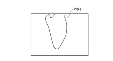
- the left / right discrimination unit 46 performs left / right discrimination from the size of the R image region indicated by the binarized R image signal (S16). In the G image signal and the B image signal, the meat part (red part and fat part) becomes dark and is not suitable for the binarization process, so the R image signal is used.
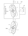
- FIG. 8A is an R image of the left work W (L) after the binarization process
- FIG. 8B is an R image of the right work W (R) after the binarization process.
- the G image signal is sent from the output extraction unit 42 to the second binarization unit 48, and the second binarization unit 48 binarizes the G image signal.
- the front / back discriminating unit 50 discriminates from the binarized image whether the image is the front side portion F or the back side portion B of the workpiece W (S18).
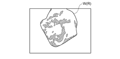
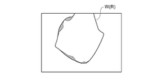
- 9A and 9B show an example of an image obtained by binarizing the right workpiece W (R) by the second binarization unit 48.
- FIG. 9A is an image of the back side portion B of the right workpiece W (R)
- FIG. 9B is an image of the front side portion F of the right workpiece W (R).
- the red-colored meat part has many R image signals and few G image signals.
- the hatched portion indicates a region where the R image signal is large, and the red flesh portion is indicated by the hatched portion.
- the area of the meat part is large, it is determined as the back side part B, and when the area of the meat part is small, it is determined as the front side part F.
- the result determined in S16 and S18 is sent to the control device 20 (S20).
- the determination at S16 it may be determined that the workpiece W is not suspended from the clamper 16.
- this determination result is also sent to the control device 20.
- FIG. 10 shows an example of the determination result sent to the control device 20.
- the determination result is stored in the image memory 52 (S22).
- the control device 20 rotates the clamper rotation device 26 so that the workpiece W is in a posture facing the X-ray irradiation side. That is, as shown in FIG. 4, when the front side portion F of the workpiece W is directed to the X-ray irradiation side, in the case of the left workpiece W (L), the left workpiece W (L) is rotated by ⁇ , and the right workpiece In the case of W (R), the right work W (R) may be rotated by + ⁇ .
- the control apparatus 20 rotates the workpiece
- the X-ray imaging station ST4 performs X-ray irradiation from the direction of the orthogonal line Ha (direction of 0 °) in FIG.
- the workpiece W is irradiated with X-rays in a state of facing the X-ray irradiation side.
- the X-ray image detected by the line sensor 34 is sent to the control device 20 and image analysis is performed by the control device 20 to determine target coordinates on the bone surface necessary for the post-scoring process and the deboning process.
- the X-ray image detected by the line sensor 34 is sent to the correctness / incorrectness determination unit 54.
- the correctness / incorrectness determination unit 54 performs normal image processing including binarization processing on the X-ray image detected by the line sensor 34 to determine the orientation of the clamper 16 and the workpiece W. Then, from the obtained direction of the clamper 16 and the workpiece W, the right / left discrimination and the front / back discrimination in the left / right discrimination device 40 are confirmed. That is, if the left / right discrimination result in the left / right discrimination device 40 is incorrect, the workpiece W does not face the X-ray irradiation side.
- the left and right discrimination and front / back discrimination of the workpiece W can be performed quickly and accurately in one step while the workpiece W is suspended from the clamper 16, so that the deboning process of the deboning device 10 can be removed. Bone processing efficiency can be improved. Further, by performing left / right discrimination and front / back discrimination, the posture of the workpiece W suspended by the clamper 16 can be accurately grasped, so that accurate scoring and deboning can be performed in a later process, and the yield is good. Deboning process becomes possible.
- the imaging of the workpiece W can be started in accordance with the timing at which the workpiece W is suspended from the clamper 16. Therefore, right / left discrimination and front / back discrimination can be started quickly with good timing.
- the correctness / incorrectness determination unit 54 can confirm the correctness of the left / right determination result and the front / back determination result in the left / right determination station ST3. Then, when the necessary X-ray image cannot be obtained in the post-scoring process or the deboning process, the work W can be omitted from the deboning process line at the exit of the X-ray imaging station ST4. It does not invite a situation such as a stop.
- the control device 20 drives the clamper rotating device 26 to further 180 the work W.
- the workpiece W can be directly opposed to the X-ray irradiation direction.
- an X-ray image required in the post-recruiting and deboning steps can be obtained, and the deboning rate can be improved.
- the arrangement of the CCD camera 22 is not limited to the direction of 145 ° from the orthogonal line Ha, and may be in the range of [145 ⁇ 20] °. Further, as shown by 22a to c in FIG. 4, even if the range is [215 ⁇ 20] °, [325 ⁇ 20] ° or [35 ⁇ 20] ° with respect to the orthogonal line Ha. Good.
- the photoelectric sensor 18 ′ is provided at the downstream end of the suspension station ST2 so that the workpiece W is detected after being suspended by the clamper 16. It may be.
- a limit switch 19 may be provided inside the slit 16 a of the clamper 16, and the limit switch 19 may detect that the workpiece W is suspended from the clamper 16.
- the operator visually checks the X-ray image detected by the line sensor 34 at the X-ray imaging station ST4, thereby confirming the correctness of the right / left determination result and the front / back determination result of the workpiece W. May be. If the left / right discrimination result or the front / back discrimination result is incorrect, the operator may operate the control device 20 to omit the workpiece W with the incorrect discrimination result from the deboning process line.
- the right and left discrimination of the pork carcass arm part can be accurately performed while being suspended from the clamp, so that the deboning process can be made more efficient if applied to a deboning process line or the like.
Landscapes
- Life Sciences & Earth Sciences (AREA)
- Physics & Mathematics (AREA)
- Engineering & Computer Science (AREA)
- General Health & Medical Sciences (AREA)
- Immunology (AREA)
- Health & Medical Sciences (AREA)
- Pathology (AREA)
- Chemical & Material Sciences (AREA)
- Analytical Chemistry (AREA)
- Biochemistry (AREA)
- General Physics & Mathematics (AREA)
- Food Science & Technology (AREA)
- Spectroscopy & Molecular Physics (AREA)
- Mathematical Physics (AREA)
- Theoretical Computer Science (AREA)
- Wood Science & Technology (AREA)
- Zoology (AREA)
- Analysing Materials By The Use Of Radiation (AREA)
- Image Analysis (AREA)
- Processing Of Meat And Fish (AREA)
Priority Applications (6)
| Application Number | Priority Date | Filing Date | Title |
|---|---|---|---|
| US14/435,518 US9451779B2 (en) | 2012-10-23 | 2012-10-23 | Left/right determination system for arm part of pig carcass |
| EP12887195.1A EP2912946B1 (de) | 2012-10-23 | 2012-10-23 | Rechts-/linksunterscheidungssystem für gliedmassenabschnitte eines schweinekadavers |
| DK12887195.1T DK2912946T3 (en) | 2012-10-23 | 2012-10-23 | RIGHT / LEFT DIFFERENCE SYSTEM FOR SWIMMING PIG BODIES |
| JP2014543052A JP5788108B2 (ja) | 2012-10-23 | 2012-10-23 | 豚屠体腕部位の左右判別システム |
| PCT/JP2012/077376 WO2014064773A1 (ja) | 2012-10-23 | 2012-10-23 | 豚屠体腕部位の左右判別システム |
| BR112015007385A BR112015007385B1 (pt) | 2012-10-23 | 2012-10-23 | sistema de determinação de esquerda/direita para uma parte de braço de uma carcaça de porco |
Applications Claiming Priority (1)
| Application Number | Priority Date | Filing Date | Title |
|---|---|---|---|
| PCT/JP2012/077376 WO2014064773A1 (ja) | 2012-10-23 | 2012-10-23 | 豚屠体腕部位の左右判別システム |
Publications (1)
| Publication Number | Publication Date |
|---|---|
| WO2014064773A1 true WO2014064773A1 (ja) | 2014-05-01 |
Family
ID=50544171
Family Applications (1)
| Application Number | Title | Priority Date | Filing Date |
|---|---|---|---|
| PCT/JP2012/077376 Ceased WO2014064773A1 (ja) | 2012-10-23 | 2012-10-23 | 豚屠体腕部位の左右判別システム |
Country Status (6)
| Country | Link |
|---|---|
| US (1) | US9451779B2 (de) |
| EP (1) | EP2912946B1 (de) |
| JP (1) | JP5788108B2 (de) |
| BR (1) | BR112015007385B1 (de) |
| DK (1) | DK2912946T3 (de) |
| WO (1) | WO2014064773A1 (de) |
Cited By (5)
| Publication number | Priority date | Publication date | Assignee | Title |
|---|---|---|---|---|
| WO2019070057A1 (ja) * | 2017-10-06 | 2019-04-11 | 株式会社前川製作所 | 骨付き肢肉の投入システム |
| US10617125B2 (en) | 2017-10-06 | 2020-04-14 | Mayekawa Mfg. Co., Ltd. | Clamping device for bone-in limb meat, loading device for bone-in limb meat, and clamping method for bone-in limb meat |
| US10709143B2 (en) | 2017-10-06 | 2020-07-14 | Mayekawa Mfg. Co., Ltd. | Clamping device for bone-in limb meat, loading device for bone-in limb meat, and clamping method for bone-in limb meat |
| WO2020218513A1 (ja) * | 2019-04-26 | 2020-10-29 | 株式会社前川製作所 | 特徴点の認識システムおよび認識方法 |
| US11033036B2 (en) | 2018-10-05 | 2021-06-15 | Mayekawa Mfg. Co., Ltd. | Clamping device for bone-in limb meat, loading device for bone-in limb meat, and clamping method for bone-in limb meat |
Families Citing this family (2)
| Publication number | Priority date | Publication date | Assignee | Title |
|---|---|---|---|---|
| US10952445B2 (en) | 2017-01-31 | 2021-03-23 | Foodmate, B.V. | Method and apparatus for continuously harvesting surrounding meat from a successive plurality animal legs |
| CN113514482B (zh) * | 2021-05-07 | 2025-04-11 | 清华大学 | 静态ct检测设备 |
Citations (4)
| Publication number | Priority date | Publication date | Assignee | Title |
|---|---|---|---|---|
| JPH06324006A (ja) * | 1993-04-30 | 1994-11-25 | Snow Brand Milk Prod Co Ltd | 肉組織の検査、加工方法およびその装置 |
| JP2002281891A (ja) * | 2001-01-18 | 2002-10-02 | Mayekawa Mfg Co Ltd | 解体ラインローディングシステム |
| WO2008096754A1 (ja) * | 2007-02-06 | 2008-08-14 | Mayekawa Mfg. Co., Ltd. | うで部位又はもも部位の脱骨方法及び装置、並びに該装置における切断動作を実行させるためのプログラム |
| JP2012056287A (ja) | 2010-09-13 | 2012-03-22 | Seiko Epson Corp | 液体噴射装置 |
Family Cites Families (5)
| Publication number | Priority date | Publication date | Assignee | Title |
|---|---|---|---|---|
| NZ334675A (en) * | 1996-08-23 | 2000-05-26 | United Kingdom Government | Method and apparatus for using image analysis to determine meat and carcass characteristics |
| CA2200545C (en) * | 1997-03-20 | 2003-01-07 | Didier Conte | Apparatus and method for removing ribs |
| US7399220B2 (en) * | 2002-08-02 | 2008-07-15 | Kriesel Marshall S | Apparatus and methods for the volumetric and dimensional measurement of livestock |
| US7039220B2 (en) * | 2002-08-14 | 2006-05-02 | C-Scan, L.L.P. | Methods and apparatus for the dimensional measurement of livestock using a single camera |
| DE102012102649A1 (de) * | 2012-03-27 | 2013-10-02 | Uwe Reifenhäuser | Verfahren und Vorrichtung zum gewichtsgenauen Schneiden eines Lebensmittelstranges |
-
2012
- 2012-10-23 EP EP12887195.1A patent/EP2912946B1/de active Active
- 2012-10-23 WO PCT/JP2012/077376 patent/WO2014064773A1/ja not_active Ceased
- 2012-10-23 JP JP2014543052A patent/JP5788108B2/ja active Active
- 2012-10-23 BR BR112015007385A patent/BR112015007385B1/pt active IP Right Grant
- 2012-10-23 DK DK12887195.1T patent/DK2912946T3/en active
- 2012-10-23 US US14/435,518 patent/US9451779B2/en active Active
Patent Citations (4)
| Publication number | Priority date | Publication date | Assignee | Title |
|---|---|---|---|---|
| JPH06324006A (ja) * | 1993-04-30 | 1994-11-25 | Snow Brand Milk Prod Co Ltd | 肉組織の検査、加工方法およびその装置 |
| JP2002281891A (ja) * | 2001-01-18 | 2002-10-02 | Mayekawa Mfg Co Ltd | 解体ラインローディングシステム |
| WO2008096754A1 (ja) * | 2007-02-06 | 2008-08-14 | Mayekawa Mfg. Co., Ltd. | うで部位又はもも部位の脱骨方法及び装置、並びに該装置における切断動作を実行させるためのプログラム |
| JP2012056287A (ja) | 2010-09-13 | 2012-03-22 | Seiko Epson Corp | 液体噴射装置 |
Non-Patent Citations (1)
| Title |
|---|
| See also references of EP2912946A4 |
Cited By (9)
| Publication number | Priority date | Publication date | Assignee | Title |
|---|---|---|---|---|
| WO2019070057A1 (ja) * | 2017-10-06 | 2019-04-11 | 株式会社前川製作所 | 骨付き肢肉の投入システム |
| US10617125B2 (en) | 2017-10-06 | 2020-04-14 | Mayekawa Mfg. Co., Ltd. | Clamping device for bone-in limb meat, loading device for bone-in limb meat, and clamping method for bone-in limb meat |
| US10681918B2 (en) | 2017-10-06 | 2020-06-16 | Mayekawa Mfg. Co., Ltd. | Loading system for bone-in limb meat |
| US10709143B2 (en) | 2017-10-06 | 2020-07-14 | Mayekawa Mfg. Co., Ltd. | Clamping device for bone-in limb meat, loading device for bone-in limb meat, and clamping method for bone-in limb meat |
| RU2737554C1 (ru) * | 2017-10-06 | 2020-12-01 | Майекава Мфг. Ко., Лтд. | Загрузочная система для мяса конечности с костью |
| US11033036B2 (en) | 2018-10-05 | 2021-06-15 | Mayekawa Mfg. Co., Ltd. | Clamping device for bone-in limb meat, loading device for bone-in limb meat, and clamping method for bone-in limb meat |
| WO2020218513A1 (ja) * | 2019-04-26 | 2020-10-29 | 株式会社前川製作所 | 特徴点の認識システムおよび認識方法 |
| JP2020183876A (ja) * | 2019-04-26 | 2020-11-12 | 株式会社前川製作所 | 特徴点認識システムおよびワーク処理システム |
| CN113767278A (zh) * | 2019-04-26 | 2021-12-07 | 株式会社前川制作所 | 特征点识别系统及识别方法 |
Also Published As
| Publication number | Publication date |
|---|---|
| EP2912946A4 (de) | 2016-06-29 |
| DK2912946T3 (en) | 2017-08-28 |
| JPWO2014064773A1 (ja) | 2016-09-05 |
| EP2912946A1 (de) | 2015-09-02 |
| US20150257396A1 (en) | 2015-09-17 |
| US9451779B2 (en) | 2016-09-27 |
| BR112015007385B1 (pt) | 2020-01-28 |
| JP5788108B2 (ja) | 2015-09-30 |
| EP2912946B1 (de) | 2017-07-12 |
| BR112015007385A2 (pt) | 2017-07-04 |
Similar Documents
| Publication | Publication Date | Title |
|---|---|---|
| JP5788108B2 (ja) | 豚屠体腕部位の左右判別システム | |
| JP2020183876A (ja) | 特徴点認識システムおよびワーク処理システム | |
| KR20180059503A (ko) | 갑각류를 가공하기 위한 센서 유도식 자동화 방법 및 시스템 | |
| KR101762165B1 (ko) | 외관 검사 장치 | |
| ES3008633T3 (en) | A method of processing a food object | |
| JP2022530772A (ja) | 吊るされた半身の豚の枝肉からの前端の切断 | |
| KR101762158B1 (ko) | 외관 검사 장치 | |
| US9675091B1 (en) | Automated monitoring in cutting up slaughtered animals | |
| CN104919273A (zh) | 红色组织结构的非接触式识别装置和方法,以及去除红色组织结构的肌肉带的总成 | |
| TW202042636A (zh) | 用於從魚片自動移除由紅肉即所謂的深色肉組成之條的裝置及方法 | |
| KR102109698B1 (ko) | 영상처리분석을 이용한 대상물 자동 선별, 분류 시스템 및 자동선별 분류방법 | |
| RU2717020C1 (ru) | Способ и устройство для выявления положения брюшка/спинки рыбы, транспортируемой с помощью транспортирующего приспособления | |
| ES2972224T3 (es) | Dispositivo y método para aflojar huesos de una pieza de carne como por ejemplo costillas de una pieza de panceta de un animal sacrificado | |
| US7460227B1 (en) | Method to detect bone fragments during the processing of meat or fish | |
| JP6814595B2 (ja) | 食肉の骨部判別装置及び食肉の骨部判別方法 | |
| CN116371755A (zh) | 一种胴体异物检测系统及检测方法 | |
| EP4249187B1 (de) | Werkzeugüberprüfungsvorrichtung, werkzeugüberprüfungsprogramm und werkzeugüberprüfungsverfahren für roboterarm | |
| JP6898721B2 (ja) | 食肉の骨部判別装置及び食肉の骨部判別方法 | |
| WO2006039932A2 (en) | Method and machine for processing of fish | |
| JP2019203845A (ja) | 汚卵検出装置 | |
| WO2006029628A1 (en) | A method and an apparatus for checking bleeding | |
| TWI852115B (zh) | 圖像處理裝置、圖像處理程式以及圖像處理方法 | |
| US8207467B2 (en) | Automatic method and system for the determination and classification of foods | |
| JP2025533790A (ja) | エッジ認識手段を備える金属板または金属薄板を加工および/または移動するための機械および方法 | |
| DK180343B1 (en) | System and method for automatic removal of foreign objects from a food surface |
Legal Events
| Date | Code | Title | Description |
|---|---|---|---|
| ENP | Entry into the national phase |
Ref document number: 2014543052 Country of ref document: JP Kind code of ref document: A |
|
| 121 | Ep: the epo has been informed by wipo that ep was designated in this application |
Ref document number: 12887195 Country of ref document: EP Kind code of ref document: A1 |
|
| WWE | Wipo information: entry into national phase |
Ref document number: 14435518 Country of ref document: US |
|
| REEP | Request for entry into the european phase |
Ref document number: 2012887195 Country of ref document: EP |
|
| REG | Reference to national code |
Ref country code: BR Ref legal event code: B01A Ref document number: 112015007385 Country of ref document: BR |
|
| WWE | Wipo information: entry into national phase |
Ref document number: 2012887195 Country of ref document: EP |
|
| NENP | Non-entry into the national phase |
Ref country code: DE |
|
| ENP | Entry into the national phase |
Ref document number: 112015007385 Country of ref document: BR Kind code of ref document: A2 Effective date: 20150401 |