WO2014064926A1 - ロボットの異常表示方法 - Google Patents
ロボットの異常表示方法 Download PDFInfo
- Publication number
- WO2014064926A1 WO2014064926A1 PCT/JP2013/006250 JP2013006250W WO2014064926A1 WO 2014064926 A1 WO2014064926 A1 WO 2014064926A1 JP 2013006250 W JP2013006250 W JP 2013006250W WO 2014064926 A1 WO2014064926 A1 WO 2014064926A1
- Authority
- WO
- WIPO (PCT)
- Prior art keywords
- abnormality
- detection
- robot
- collision
- display
- Prior art date
- Legal status (The legal status is an assumption and is not a legal conclusion. Google has not performed a legal analysis and makes no representation as to the accuracy of the status listed.)
- Ceased
Links
Images











Classifications
-
- B—PERFORMING OPERATIONS; TRANSPORTING
- B25—HAND TOOLS; PORTABLE POWER-DRIVEN TOOLS; MANIPULATORS
- B25J—MANIPULATORS; CHAMBERS PROVIDED WITH MANIPULATION DEVICES
- B25J9/00—Program-controlled manipulators
- B25J9/16—Program controls
- B25J9/1674—Program controls characterised by safety, monitoring, diagnostic
-
- B—PERFORMING OPERATIONS; TRANSPORTING
- B25—HAND TOOLS; PORTABLE POWER-DRIVEN TOOLS; MANIPULATORS
- B25J—MANIPULATORS; CHAMBERS PROVIDED WITH MANIPULATION DEVICES
- B25J19/00—Accessories fitted to manipulators, e.g. for monitoring, for viewing; Safety devices combined with or specially adapted for use in connection with manipulators
- B25J19/06—Safety devices
-
- B—PERFORMING OPERATIONS; TRANSPORTING
- B25—HAND TOOLS; PORTABLE POWER-DRIVEN TOOLS; MANIPULATORS
- B25J—MANIPULATORS; CHAMBERS PROVIDED WITH MANIPULATION DEVICES
- B25J9/00—Program-controlled manipulators
- B25J9/16—Program controls
- B25J9/1674—Program controls characterised by safety, monitoring, diagnostic
- B25J9/1676—Avoiding collision or forbidden zones
-
- G—PHYSICS
- G06—COMPUTING OR CALCULATING; COUNTING
- G06F—ELECTRIC DIGITAL DATA PROCESSING
- G06F17/00—Digital computing or data processing equipment or methods, specially adapted for specific functions
- G06F17/10—Complex mathematical operations
- G06F17/11—Complex mathematical operations for solving equations, e.g. nonlinear equations, general mathematical optimization problems
-
- G—PHYSICS
- G05—CONTROLLING; REGULATING
- G05B—CONTROL OR REGULATING SYSTEMS IN GENERAL; FUNCTIONAL ELEMENTS OF SUCH SYSTEMS; MONITORING OR TESTING ARRANGEMENTS FOR SUCH SYSTEMS OR ELEMENTS
- G05B2219/00—Program-control systems
- G05B2219/30—Nc systems
- G05B2219/37—Measurements
- G05B2219/37622—Detect collision, blocking, stall by change, lag in position
-
- G—PHYSICS
- G05—CONTROLLING; REGULATING
- G05B—CONTROL OR REGULATING SYSTEMS IN GENERAL; FUNCTIONAL ELEMENTS OF SUCH SYSTEMS; MONITORING OR TESTING ARRANGEMENTS FOR SUCH SYSTEMS OR ELEMENTS
- G05B2219/00—Program-control systems
- G05B2219/30—Nc systems
- G05B2219/37—Measurements
- G05B2219/37624—Detect collision, blocking by measuring change of velocity or torque
-
- Y—GENERAL TAGGING OF NEW TECHNOLOGICAL DEVELOPMENTS; GENERAL TAGGING OF CROSS-SECTIONAL TECHNOLOGIES SPANNING OVER SEVERAL SECTIONS OF THE IPC; TECHNICAL SUBJECTS COVERED BY FORMER USPC CROSS-REFERENCE ART COLLECTIONS [XRACs] AND DIGESTS
- Y10—TECHNICAL SUBJECTS COVERED BY FORMER USPC
- Y10S—TECHNICAL SUBJECTS COVERED BY FORMER USPC CROSS-REFERENCE ART COLLECTIONS [XRACs] AND DIGESTS
- Y10S901/00—Robots
- Y10S901/49—Protective device
Definitions
- the present invention relates to an abnormality display method for a robot driven by a motor via a reduction gear.
- the high accuracy of sensorless collision detection increases the possibility of erroneously detecting a robot abnormal state as a collision even when it is not an actual collision.
- the collision detection function may detect an abnormality before other abnormality detection functions, and an erroneous display such as “collision occurrence” may occur even though no collision has occurred.
- the high accuracy of the sensorless collision detection has an advantage of detecting the failure promptly, but also causes the failure cause to be difficult to understand. The reason why erroneous collision detection occurs will be described below with reference to FIGS.
- FIG. 1 is a schematic configuration diagram showing a vertical articulated 6-axis robot as a typical example of a robot.
- the vertical articulated 6-axis robot includes a robot mechanism (101), a robot control device (102), and an operation display device (103).
- FIG. 2 is a flowchart showing the entire process of abnormality display.
- the entire process of abnormality display is performed in the robot controller (102).
- a motor lock detection process for detecting an abnormality when a robot failure occurs in addition to the collision detection process, a motor lock detection process for detecting an abnormality when a robot failure occurs, an overload detection process, and a position deviation over detection process are added.
- the entire process of abnormal display shown in FIG. 2 is repeated every period ⁇ T, and the period ⁇ T assumes several milliseconds.
- step 2-1 motor lock detection processing is performed.
- step 2-6 when motor lock is detected, “motor lock detected” is displayed as an abnormality display on the operation display device (103) of FIG. If the motor lock is detected, an abnormal state has already occurred and an abnormality is displayed, so the abnormality display process is terminated in step 2-6. If the motor lock is not detected in step 2-6, the process proceeds to step 2-2.
- step 2-2 overload detection processing is performed.
- step 2-7 when an overload is detected, “overload detection” is displayed as an abnormality display on the operation display device (103) of FIG. If an overload is detected, an abnormal state has already occurred and an abnormality is displayed, so the abnormality display process is terminated in step 2-7. If no overload is detected in step 2-7, the process proceeds to step 2-3.
- step 2-3 position deviation over detection processing is performed.
- step 2-8 when a position deviation over is detected, “position deviation over detection” is displayed as an abnormality display on the operation display device (103) of FIG. If a position deviation over is detected, an abnormal state has already occurred and an abnormal display has been made, so the abnormal display process is terminated in step 2-8. If no position deviation over is detected in step 2-8, the process proceeds to step 2-4.
- step 2-4 a collision detection process described below with reference to FIG. 3 is executed.
- a dynamics calculation method There are two methods for obtaining the collision force without a sensor: a dynamics calculation method and a disturbance estimation observer method.
- the dynamics calculation method first, the reduction gear output torque is obtained by subtracting the torque lost due to friction and the inertia of the motor and reduction gear from the torque generated by the driving current of the motor.
- the collision force is obtained by subtracting the robot dynamic torque obtained by the robot dynamics calculation from the reducer output torque.
- the disturbance estimation observer method obtains a collision force using a disturbance estimation observer. (For example, refer to Patent Document 1).
- a dynamics calculation method having excellent estimation accuracy will be described as an example.
- FIG. 3 is a control block diagram of the dynamic calculation method.
- 6 is a position control block.
- a position command ⁇ com (3) obtained by integrating the velocity component d ⁇ com (1) of the position command by the integration element 40 and a motor position ⁇ m (4) are input to the position control block (6).
- the speed loop command ⁇ com (7) is output from the position proportional gain (5).
- 10 is a speed control block.
- a speed loop command ⁇ com (7) and a motor position ⁇ m (4) are input to the speed control block (10). Then, a difference value between the speed loop command ⁇ com (7) and the motor speed ⁇ m (2) obtained by differentiating the motor position ⁇ m (4) by the differential element (32) is obtained, and the speed proportional gain (8) and the speed integral gain ( The motor current Im (11) is output via 9).
- 18 is a block showing a motor and external force. Assuming that the reduction gear is a rigid body, ⁇ m (13) is expressed by equation (1) when viewed from the motor drive side, and expressed by equation (2) when viewed from the load side.
- K ⁇ K ⁇ ⁇ sgn (3)
- K ⁇ is the magnitude of dynamic friction
- the collision torque ⁇ dis (16) can be obtained by transforming into the following equation (4) from the equations (1) and (2).
- reference numeral 30 represents Expression (4) as a collision torque estimation block.
- the estimated dynamic torque value ⁇ dyno (29) is obtained by the dynamic calculation by the dynamic torque calculation block (26).
- the dynamic torque calculation block (26) differentiates the motor position ⁇ m (4) of all axes constituting the robot, the motor speed ⁇ m (2) obtained by differentiating the motor position ⁇ m (4), and the motor speed ⁇ m (2).
- the dynamic calculation is executed using the motor acceleration ⁇ m (90) and the machine parameters of the robot (arm length, arm mass, center of gravity position, inertia around the center of gravity position).
- the collision torque estimation block (30) outputs the collision torque estimated value ⁇ diso (28) to the collision determination block (31).
- the collision determination block (31) detects a collision according to the following equation (5) using a predetermined collision detection threshold ⁇ th.
- Step 2-5 if Expression (5) is established, “collision detection” is displayed as an abnormality display on the operation display device (103) of the robot of FIG. 1, and the abnormality display processing is terminated. In step 2-5, if the equation (5) is not established, the abnormality display process is terminated without displaying the abnormality. Then, the entire abnormal display process is started for each period ⁇ T.
- the collision torque estimated value ⁇ diso (28) can be obtained with high accuracy.
- Lagrange method and a Newton Euler method as a method for obtaining the dynamic torque in the dynamic torque calculation block (26).
- Lagrangian method a 6-axis vertical articulated robot requires a product-sum operation of almost 100,000 times. However, this amount of calculation can be calculated within a few milliseconds based on the current processing capability of the CPU.
- the Newton Euler method the product-sum calculation amount is less than 10,000 times, so the calculation time is not a problem. Since the Newton Euler method is a so-called recurrence method that uses the result of the previous equation in the following equation, there is a possibility that a cumulative error of operation may occur. However, if processing is performed with data of 32 bits or more, there is no problem in the accumulated error of calculation.
- the current CPU can calculate the dynamic torque ⁇ dyn (14) with an error within 10% of the maximum motor torque ratio. If the terms other than the dynamic torque ⁇ dyn (14) on the right side of the equation (4) can also be calculated with an error within 10% of the motor maximum torque ratio, the collision torque estimated value ⁇ diso (28) % Error can be obtained.
- the collision detection function can detect a collision if an abnormality with a motor maximum torque ratio of about 20% is observed for several milliseconds.
- the collision detection threshold value ⁇ th is set low (about 20% of the maximum motor torque ratio)
- a failure other than a collision will be detected quickly.
- the motor-generated torque ⁇ m is increased by an amount corresponding to the increase in the dynamic friction torque ⁇ .
- the motor current Im on the right side of the equation (4) increases.
- the dynamic friction torque ⁇ used on the right side of the equation (4) is calculated using a value measured in advance in the normal state, the collision torque ⁇ dis on the left side of the equation (4) increases despite no collision. To do. If the magnitude of the collision torque ⁇ dis exceeds the maximum motor torque ratio of 20% even for a few milliseconds, it will be erroneously detected as a collision detection.
- the cause of the increase in the motor torque Im on the right side of the equation (4) and the increase in the collision torque ⁇ dis cannot be specified. That is, it cannot be distinguished whether it is caused by an actual collision of a robot or an increase in friction torque due to a failure of a motor or a speed reducer. Therefore, if the collision detection threshold ⁇ th is set low (collision detection sensitivity is increased) in order to reduce the damage at the time of the robot collision, the probability of occurrence of erroneous collision detection is also increased.
- the motor lock detection function detects the situation in which the motor has been operating but it has hardly moved. Even if the motor generated torque ⁇ m (shown by the equation (1)) exceeds the predetermined motor torque threshold ⁇ mth (91), if the friction torque increased due to the failure is large, the motor speed ⁇ m (2) becomes the predetermined motor speed. Does not rise above the threshold ⁇ mth. When this state continues for a predetermined motor lock detection time threshold LKth or more, the motor lock detection function is determined to be abnormal.
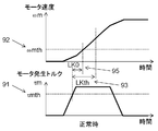
- FIG. 5A is a graph showing the motor speed ⁇ m (2) and the motor generated torque ⁇ m (13) in a normal state. After a time LK0 (95) smaller than the motor lock detection time threshold LKth (93) has elapsed after the motor generated torque ⁇ m (13) exceeds the motor torque threshold ⁇ mth (91), the motor speed ⁇ m (2) is The speed threshold value ⁇ mth (92) is exceeded. In this case, the motor lock is not detected.
- FIG. 5B is a graph showing a motor speed ⁇ m (2) and a motor generated torque ⁇ m (13) at the time of abnormality that a motor lock is detected due to an increase in friction torque due to a failure of a motor or a speed reducer.
- the motor is compared with the normal state (indicated by the dotted line) due to the increase in friction torque due to the failure of the motor or the speed reducer.
- the increase in speed ⁇ m (2) is slow. Therefore, even if the motor speed ⁇ m (2) reaches the motor lock detection time threshold LKth (93), it does not reach the motor speed threshold ⁇ mth (92). In this case, motor lock is detected.
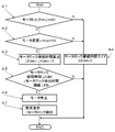
- FIG. 4 is a flowchart of the motor lock detection.
- the motor lock detection process is executed every fixed period ⁇ T.
- Step 4-1 it is determined whether or not the motor generated torque ⁇ m is equal to or greater than the motor torque threshold ⁇ mth (91). If the motor generated torque ⁇ m is equal to or greater than the motor torque threshold ⁇ mth (91), it is determined as “Y”, and the process proceeds to Step 4-2.
- step 4-2 it is determined whether or not the motor speed ⁇ m (2) is equal to or less than the motor speed threshold ⁇ mth (92). If the motor speed ⁇ m (2) is equal to or less than the motor speed threshold ⁇ mth (92), it is determined as “Y”, and the process proceeds to Step 4-3.
- step 4-3 the motor lock duration time LKdet is calculated by equation (5), and the process proceeds to step 4-5.
- LKdet LKdet + ⁇ T (6)
- ⁇ T is a motor lock detection processing cycle.
- step 4-3 the length of time in which both step 4-1 and step 4-2 are determined to be “Y” is measured by adding the motor lock detection processing period ⁇ T.
- step 4-1 or step 4-2 determines whether the determination in step 4-1 or step 4-2 is “N”. If the determination in step 4-1 or step 4-2 is “N”, the process proceeds to step 4-4, the motor lock duration time LKdet is reset to 0, and the motor lock detection process ends.
- step 4-5 it is determined whether or not the motor lock duration time LKdet is equal to or greater than the motor lock detection time threshold value LKth (93).
- step 4-7 If the motor lock duration time LKdet is equal to or greater than the motor lock detection time threshold value LKth (93), it is determined “Y”, and the process proceeds to step 4-6. In this case, it is determined that the motor is locked, and the motor is stopped in step 4-6. Subsequently, in step 4-7, an abnormality display of “motor lock detection” is performed, and the motor lock detection process is terminated.
- the abnormality display is displayed on the operation display device (103) shown in FIG.
- step 4-5 If the determination in step 4-5 is “N”, it is determined that the motor is not locked, and the motor lock detection process is terminated.
- the motor lock detection time threshold value LKth (93) needs to be larger than the required time LK0 (95) at the normal time.
- the motor lock detection time threshold LKth (93) is several hundred milliseconds to several seconds, which is slower than the collision detection function detecting within several milliseconds.
- the collision detection threshold ⁇ th is set low (collision detection sensitivity is set high)
- the collision is detected first before the motor lock is detected even though the collision is not actually detected, and the abnormality display is also “ Only “collision detection” is displayed.
- the motor lock detection at step 2-6 continues to be determined as “N”
- the collision detection at step 2-5 determines “Y”.
- the overload detection function detects an overload abnormality so that the accumulated time value of the current that drives the motor does not exceed the limit value of the motor time characteristic curve.
- the motor generated torque is proportional to the current that drives the motor, and the limit value of the motor time characteristic curve indicates the upper limit of the winding temperature of the motor.
- FIG. 7 is a graph showing the relationship between the motor current for driving the motor and time.
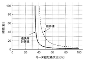
- the limit value (dotted line) of the motor time limit curve shown in FIG. 7 is about 100 seconds when the maximum current ratio is 40%, 25 seconds when the maximum current ratio is 50%, and about 8 when the maximum current ratio is 70%. Seconds. Overload detection is performed so that it is below this limit value.
- FIG. 6 is a flowchart of overload detection.
- the overload detection process is executed every fixed period ⁇ T.
- step 6-1 the overload detection value OLdet is obtained by the following equation (8).
- OLdet OLdet + (
- Imth is an overload detection current threshold
- ⁇ T is an overload detection cycle.
- Step 6-2 it is determined whether or not the overload detection value OLdet is equal to or greater than the overload threshold OLth. That is, it is determined whether the condition of the following formula (9) is satisfied.
- Step 6-3 the motor is stopped, and subsequently, in step 6-4, "abnormal display” indicating “overload detection” is performed, and the overload detection processing is terminated.
- the “abnormal display” is displayed on the operation display device (103) shown in FIG.
- step 6-2 If the determination in step 6-2 is “N”, it is determined that there is no overload condition, and the overload detection process is terminated.
- the overload detection threshold characteristic (solid line) is set so as to be lower than the limit value (dotted line), which indicates that the calculation method of the overload detection value OLdet represented by the equation (8) is appropriate.
- overload detection takes several seconds even when the motor current is 100% of the maximum current ratio.
- the time required for this overload detection is slower than the collision detection function detects within a few milliseconds. That is, when a motor or reduction gear failure occurs from the state where no overload abnormality has occurred, the motor rotation becomes heavier and the motor current (motor generated torque) increases by about 20% in terms of the maximum current ratio. Thus, even if a motor or speed reducer failure occurs, it takes a few seconds or more to detect an overload abnormality, and there is a very high possibility that a false collision detection will occur first. Referring to FIG. 2, while it is determined “N” in the overload detection in step 2-7 and continues, “Y” is determined in the collision detection in step 2-5.
- the motor torque ⁇ m (90) generated by differentiating the motor position ⁇ m (4) twice is used for the dynamic torque calculation block (26). Therefore, the change in the motor position ⁇ m (4) greatly affects the motor acceleration ⁇ m (90).
- differentiation in digital control is generally performed by the difference between the current sample value and the previous sample value one cycle before the sample. Therefore, an example is shown.
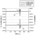
- FIG. 9 is a graph showing a motor position waveform when an abnormality occurs in the motor position detector.
- FIG. 10 is a graph showing a speed waveform when an abnormality occurs in the motor position detector.
- FIG. 11 is a graph showing an acceleration waveform when an abnormality occurs in the motor position detector.
- the error e ⁇ m (86) of the motor position ⁇ m (4) at 300 milliseconds when the abnormality occurred is calculated based on the value after 500 milliseconds (12.5 revolutions), it is about 4.7% (about 0.8. 15 rotations).
- the error e ⁇ m (87) of the motor speed ⁇ m (2) is also about 120% when calculated based on the value after 500 milliseconds (50 revolutions / second).
- the error e ⁇ m (88) of the motor acceleration ⁇ m (90) is about ⁇ 33333% when calculated on the basis of the value (100 rotations / second 2 ) after 500 milliseconds. Therefore, the accuracy of the dynamic torque ⁇ dyn (14) obtained by the dynamic torque calculation block (26) is greatly affected, and there is a high possibility of causing a collision detection error.
- the cause of the motor position ⁇ m (4) not changing cannot be specified. That is, it is unclear whether the collision actually occurred and the robot stopped, or because the motor position detector (99) was abnormal and the motor position ⁇ m (4) was not updated. Therefore, if the collision detection function is to work effectively, the occurrence of erroneous collision detection cannot be avoided.
- a function that detects that there is an abnormality in the motor position detector (99) that detects the motor position ⁇ m (4) includes a position deviation over detection function.
- FIG. 12 is a flowchart of the position deviation over detection.
- the position deviation over detection process is executed every fixed period ⁇ T.
- Step 12-1 the position deviation over detection value ⁇ det is calculated as an absolute value of the difference between the position command ⁇ com (3) and the motor position ⁇ m (4) as shown in the following equation (10).
- Step 12-2 the position deviation over detection value ⁇ det is compared with the position deviation over detection threshold ⁇ th to determine whether or not the following equation (11) is satisfied.
- step 12-4 “abnormal position deviation over” abnormality is displayed, and the position deviation over detection process is terminated.
- the abnormality display is displayed on the operation display device (103) shown in FIG.
- step 12-2 If the determination in step 12-2 is “N”, it is determined that the position deviation is not over, and the position deviation over detection process is terminated.
- the position deviation over detection threshold ⁇ th in the equation (11) is set to about several rotations so that a position deviation due to control delay is not erroneously detected.
- the position deviation due to the control delay is one rotation and the position deviation over detection threshold ⁇ th is set to two rotations.
- the position deviation over detection value ⁇ det is about 1.15 rotations.
- the condition of Expression (11) is not satisfied, and the position deviation over is not detected.
- the collision detection is erroneously detected. In other words, the collision is detected first even though there is no actual collision, and the abnormality display is displayed only as “collision detection”. Referring to FIG. 2, while the position deviation over detection in step 2-8 continues to be determined as “N”, the collision detection in step 2-5 determines “Y”.
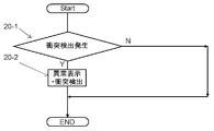
- the single abnormality display process shown in FIG. 20 is executed as the abnormality display process at the time of collision detection in step 2-5 in FIG.
- step 2-4 the collision detection in step 2-4 is detected first. "Is displayed abnormally only.
- the present invention solves the above-described problems, and provides a robot abnormality display method capable of displaying information useful for grasping the situation at the time of occurrence of erroneous collision detection.
- the robot abnormality display method of the present invention is a robot abnormality detection method that detects a plurality of abnormalities including at least a collision detection based on a value detected during operation of the robot, and displays the occurrence of the abnormality.
- This is an abnormal display method. Furthermore, it has the collision detection process which detects the collision of a robot. Furthermore, it has the collision detection display process which displays that the collision was detected as an abnormal display. Furthermore, an abnormality display step of displaying that an abnormality has occurred as an abnormality display also for at least one of a plurality of abnormality detection items different from the collision detection.
- the robot abnormality display method of the present invention may be performed by selecting abnormality display of a plurality of abnormality detection items in the abnormality display step.
- each of the plurality of abnormality detection items includes an abnormality determination threshold for determining an abnormality, and a robot collision smaller than the abnormality determination threshold.
- a display enable / disable threshold for displaying that an abnormality has occurred is displayed in addition to displaying that a collision has been detected.
- an abnormality determination value based on a value detected during the operation of the robot may exceed the display availability threshold value and display that an abnormality has occurred as an abnormality display.
- each of the plurality of abnormality detection items includes an abnormality determination threshold for determining an abnormality, and a robot collision smaller than the abnormality determination threshold. It is preferable that a display availability threshold value for displaying that an abnormality has occurred is displayed together with displaying that a collision has been detected. Furthermore, it is preferable that priorities are set for a plurality of abnormality detection items. Furthermore, it is preferable to determine whether or not the abnormality determination value based on the value detected during the operation of the robot has exceeded the display availability threshold value in descending order of priority. Furthermore, it is preferable to perform abnormality display only for abnormality detection items that exceed the display availability threshold. Further, for an abnormality detection item having a lower priority than an abnormality detection item that has performed an abnormality display, it is not necessary to determine whether or not the abnormality determination value has exceeded the display availability threshold and perform abnormality display.
- the robot abnormality display method of the present invention may determine a display availability threshold for each abnormality detection item based on a set collision detection threshold.
- the ratio of the abnormality determination value based on the value detected during the operation of the robot with respect to the abnormality determination threshold for each abnormality detection item may be obtained. Furthermore, it is preferable to perform abnormality display together with collision detection only for abnormality detection items having the highest abnormality determination value ratio.
- an abnormality determination threshold value for determining an abnormality may be set in each of the plurality of abnormality detection items. Further, for each of a plurality of abnormality detection items, a ratio of abnormality determination values based on values detected during operation of the robot with respect to the abnormality determination threshold value may be obtained. Furthermore, it is good to display the ratio of the abnormality determination value for each abnormality detection item in addition to displaying that the collision has been detected when a robot collision is detected.
- an abnormality determination threshold value for determining an abnormality may be set in each of the plurality of abnormality detection items. Further, for each of a plurality of abnormality detection items, a ratio of abnormality determination values based on values detected during operation of the robot with respect to the abnormality determination threshold value may be obtained. Further, in addition to displaying that a collision has been detected when a robot collision is detected, it is preferable to display the ratio of the abnormality determination value of each abnormality detection item only when the abnormality determination value exceeds the display availability threshold.
- the robot abnormality display method includes, as a plurality of abnormality detection items, at least of detection of lock of a motor driving the robot, detection of overload of the motor, and detection of position deviation of the robot. It is good to include one.
- the robot abnormality display method of the present invention when the collision detection occurs, the situation of other abnormality detection means is also displayed, which helps to grasp the operation state of the robot when the collision erroneous detection occurs. Is.
- FIG. 1 is a diagram showing a schematic configuration of a vertical articulated 6-axis robot as a representative example to which the present invention is applied.
- FIG. 2 is a flowchart showing the entire abnormal display process according to the embodiment of the present invention.
- FIG. 3 is a control block diagram of the dynamic calculation method in the embodiment of the present invention.
- FIG. 4 is a flowchart showing motor lock detection in the embodiment of the present invention.
- FIG. 5A is a graph showing temporal changes in motor speed and motor torque at normal times.
- FIG. 5B is a graph showing temporal changes in motor speed and motor torque when motor lock is detected.
- FIG. 6 is a flowchart showing overload detection in the embodiment of the present invention.
- FIG. 1 is a diagram showing a schematic configuration of a vertical articulated 6-axis robot as a representative example to which the present invention is applied.
- FIG. 2 is a flowchart showing the entire abnormal display process according to the embodiment of the present invention.
- FIG. 3 is a control block diagram
- FIG. 7 is a graph showing a motor time characteristic curve (limit of increase in winding temperature of the motor).
- FIG. 8 is a graph showing overload detection threshold characteristics.
- FIG. 9 is a diagram showing a motor position waveform when an abnormality occurs in the motor position detector.
- FIG. 10 is a diagram showing a motor speed waveform when a motor position detector abnormality occurs.
- FIG. 11 is a diagram showing a motor acceleration waveform when a motor position detector abnormality occurs.
- FIG. 12 is a flowchart showing position deviation over detection in the embodiment of the present invention.
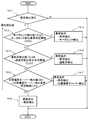
- FIG. 13 is a flowchart showing the first multiple abnormality display process in the first embodiment of the present invention.
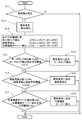
- FIG. 14 is a flowchart showing a second multiple abnormality display process according to Embodiment 2 of the present invention.
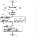
- FIG. 15 is a flowchart showing third multiple abnormality display processing according to Embodiment 3 of the present invention.
- FIG. 16 is a flowchart showing a fourth multiple abnormality display process according to Embodiment 4 of the present invention.
- FIG. 17 is a flowchart showing a fifth multiple abnormality display process in the fifth embodiment of the present invention.
- FIG. 18 is a flowchart showing a sixth multiple abnormality display process according to Embodiment 6 of the present invention.
- FIG. 19 is a flowchart showing a seventh multiple abnormality display process in the seventh embodiment of the present invention.
- FIG. 20 is a flowchart showing a conventional single abnormality display process.
- Embodiment 1 of the present invention will be described below with reference to the drawings.
- symbol is attached
- the first multiple abnormality display process shown in the flowchart of FIG. 13 is executed as the collision detection occurrence abnormality display process of step 2-5 of FIG. 2 described in the background art.
- step 13-3 to step 13-8 processing (step 13-3 to step 13-8) for selecting and displaying at least one abnormality display among a plurality of abnormality detection items different from the collision detection is provided.
- a display possibility threshold value smaller than the abnormality determination threshold value is set.
- an abnormality determination value (motor lock detection value LKdet, excessive value based on values detected during the operation of the robot (for example, motor generation torque ⁇ m, motor speed ⁇ m, motor current Im, motor position ⁇ m).
- LKdet excessive value based on values detected during the operation of the robot
- the load detection value OLdet and the position deviation over detection value ⁇ det exceed the display enable / disable threshold, an abnormality is displayed as an abnormality display.
- step 13-1 it is determined whether or not a robot collision detection has occurred.
- step 13-1 when a robot collision is detected, it is determined as “Y”, and the process proceeds to step 13-2.
- step 13-2 an abnormality display of “collision detection” is performed, and the process proceeds to step 13-3.
- step 13-1 if no robot collision is detected, it is determined as “N”, and nothing is performed thereafter, and the first multiple abnormality display process is terminated.
- Step 13-3 it is determined whether or not the motor lock detection value LKdet exceeds the motor lock detection display enable / disable threshold value LKthd.
- step 13-3 if the motor lock detection value LKdet exceeds the motor lock detection display enable / disable threshold LKthd, it is determined “Y”, and the process proceeds to step 13-4.
- step 13-3 if the motor lock detection value LKdet does not exceed the motor lock detection display enable / disable threshold LKthd, it is determined “N”, and the process proceeds to step 13-5.
- the motor lock detection display enable / disable threshold value LKthd is set to be smaller than the motor lock detection time threshold value LKth as shown in the following equation (12).
- Step 13-4 “Motor lock detection” is additionally displayed as an abnormality display, and the process proceeds to Step 13-5.
- Step 13-5 it is determined whether or not the overload detection value OLdet exceeds the overload detection display availability threshold OLthd. In step 13-5, if the overload detection value OLdet exceeds the overload detection display enable / disable threshold OLthd, it is determined “Y”, and the process proceeds to step 13-6. In step 13-5, if the overload detection value OLdet does not exceed the overload detection display enable / disable threshold value OLthd, it is determined “N”, and the process proceeds to step 13-7.
- the overload detection display availability threshold value OLthd is set to be smaller than the overload threshold value OLth as shown in the following formula (13).
- Step 13-6 “Overload detection” is additionally displayed as an abnormality display, and the process proceeds to Step 13-7.
- Step 13-7 it is determined whether or not the position deviation over detection value ⁇ det exceeds the position deviation over detection display enable / disable threshold value ⁇ thd.
- step 13-7 if the position deviation over detection value ⁇ det exceeds the position deviation over detection display enable / disable threshold value ⁇ thd, it is determined “Y”, and the process proceeds to step 13-8.
- step 13-7 it is determined “N” if the position deviation over detection value ⁇ det does not exceed the position deviation over detection display enable / disable threshold value ⁇ thd, and the first multiple abnormality display process is terminated.
- the position deviation over-detection display possibility threshold ⁇ thd is set to be smaller than the position deviation over-detection threshold ⁇ th as shown by the following equation (14).
- step 13-8 "Position deviation over detection" is additionally displayed as an abnormality display, and the first multiple abnormality display process is terminated.
- “Motor lock detection” is displayed in addition to “collision detection” as the abnormality display at that time.
- “overload detection” is displayed in addition to “collision detection”
- position deviation over detection is displayed in addition to “collision detection”, it can be estimated that an abnormality of the motor position detector has occurred.
- priorities are set for a plurality of abnormality detection items. Then, in descending order of priority, abnormality determination values (motor lock detection value LKdet, overload, etc.) based on values detected during robot operation (for example, motor torque ⁇ m, motor speed ⁇ m, motor current Im, motor position ⁇ m). It is determined whether or not the detection value OLdet and the position deviation over-detection value ⁇ det have exceeded the display availability threshold. Only abnormality detection items that exceed the display availability threshold value are displayed abnormally.
- abnormality determination values for example, motor torque ⁇ m, motor speed ⁇ m, motor current Im, motor position ⁇ m.
- step 14-3 and 14- For the abnormality detection item having a lower priority than the abnormality detection item for which abnormality display has been performed, it is not determined whether or not the abnormality determination value has exceeded the display availability threshold and the abnormality display is not performed (steps 14-3 and 14-). 5. The process is terminated by moving to any one of steps 14-7).
- the plurality of abnormality detection items are “motor lock detection”, “overload detection”, and “position deviation over detection” in order from the highest priority.
- step 14-1 it is determined whether or not a robot collision detection has occurred. If the robot collision is detected in step 14-1, it is determined “Y”, and the process proceeds to step 14-2. In step 14-1, if the robot collision detection does not occur, it is determined as “N”, and nothing is performed thereafter, and the second plural abnormality display process is terminated.
- Step 14-2 it is determined whether or not the motor lock detection value LKdet exceeds the motor lock detection display enable / disable threshold LKthd for the motor lock detection with the highest priority.
- step 14-2 if the motor lock detection value LKdet exceeds the motor lock detection display enable / disable threshold LKthd, it is determined “Y”, and the process proceeds to step 14-3.
- step 14-2 if the motor lock detection value LKdet does not exceed the motor lock detection display enable / disable threshold LKthd, it is determined “N”, and the process proceeds to step 14-4.
- Step 14-3 “collision detection” and “motor lock detection” are displayed abnormally, and the second multiple abnormality display processing is terminated.
- Step 14-4 it is determined whether or not the overload detection value OLdet exceeds the overload detection display enable / disable threshold value OLthd for the next highest priority overload detection. In step 14-4, if the overload detection value OLdet exceeds the overload detection display enable / disable threshold value OLthd, it is determined “Y”, and the process proceeds to step 14-5. In step 14-4, if the overload detection value OLdet does not exceed the overload detection display enable / disable threshold value OLthd, it is determined “N”, and the process proceeds to step 14-6.
- step 14-5 “collision detection” and “overload detection” are displayed abnormally, and the second multiple abnormality display process is terminated.
- Step 14-6 it is determined whether or not the position deviation over detection value ⁇ det exceeds the position deviation over detection display enable / disable threshold value ⁇ thd for the position deviation over detection with the lowest priority.
- step 14-6 if the position deviation over detection value ⁇ det exceeds the position deviation over detection display enable / disable threshold value ⁇ thd, it is determined “Y”, and the process proceeds to step 14-7.
- step 14-6 it is determined “N” if the position deviation over detection value ⁇ det does not exceed the position deviation over detection display enable / disable threshold value ⁇ thd, and the process proceeds to step 14-8.
- step 14-7 “collision detection” and “position deviation over detection” are displayed abnormally, and the second multiple abnormality display processing is terminated.
- step 14-8 only “collision detection” is displayed as abnormal, and the second multiple abnormality display processing is terminated.
- each abnormality detection item is based on the collision detection threshold for each abnormality detection item that is set with respect to the first multiple abnormality display process of FIG. 13 in the first embodiment.
- a process for determining a display possibility threshold for the item is added.
- step 15-1 it is determined whether or not a robot collision detection has occurred.
- step 15-1 if a robot collision is detected, it is determined “Y”, the process proceeds to step 15-2, an abnormality display of “collision detection” is performed, and the process proceeds to step 15-A.
- step 15-1 if the collision detection of the robot does not occur, it is determined as “N”, and nothing is performed thereafter, and the third multiple abnormality display process is terminated.
- Step 15-A is a process added to determine the display availability threshold for each abnormality detection item based on the set collision detection threshold.
- step 15-A based on the collision detection threshold ⁇ th, as shown in the following formulas (15-1) to (15-3), the motor lock detection display availability threshold LKthd, the overload detection display availability threshold OLthd, A position deviation over detection display enable / disable threshold value ⁇ thd is calculated.
- LKthd kthA1 ⁇ ⁇ th + kthB1 (15-1)
- OLthd kthA2 ⁇ ⁇ th + kthB2
- ⁇ thd kthA3 ⁇ ⁇ th + kthB3
- kthA1, kthA2, and kthA3 collision detection threshold ( ⁇ th) proportional coefficients
- KthB1, kthB2, and kthB3 are addition coefficients.
- the reason why the abnormality detection display possibility threshold is obtained based on the collision detection threshold ⁇ th as described above is that when the collision detection threshold ⁇ th is large (the collision detection sensitivity is low), the possibility of erroneous collision detection is reduced. If collision detection is not performed, the other abnormality detection display may be rather complicated to judge the situation when collision detection occurs. That is, the higher the collision detection threshold ⁇ th is, the higher the abnormality detection display availability threshold is set to prevent multiple abnormality display.
- step 15-A the motor lock detection display enable / disable threshold value LKthd, the overload detection display enable / disable threshold value OLthd, and the position deviation over-detection display enable / disable threshold value ⁇ thd calculated in step 15-A are set to step 15-3, step 15-5, step 15- 7 is used for determination.
- the processing after step 15-3 is the same as the processing after step 13-3 in FIG. 13 in the first embodiment.
- a display availability threshold value for each abnormality detection item is determined based on the set collision detection threshold value with respect to the second multiple abnormality display process of FIG. 14 in the second embodiment. (Step 16-A) is added.
- step 16-A is the same as the processing in step 15-A in FIG. 15 in the third embodiment.
- the processing after step 16-3 is the same as the processing after step 14-3 of FIG. 14 in the second embodiment.
- each abnormality detection item is based on values (for example, motor torque ⁇ m, motor speed ⁇ m, motor current Im, motor position ⁇ m) detected during the operation of the robot with respect to the abnormality determination threshold.
- the ratio of the abnormality determination value (motor lock detection value LKdet, overload detection value OLdet, position deviation over detection value ⁇ det) is obtained. Only the abnormality detection item with the highest ratio of the abnormality determination value has a process of performing abnormality display together with collision detection.
- step 17-1 it is determined whether or not a robot collision detection has occurred.
- step 17-1 when a robot collision is detected, it is determined “Y”, and the process proceeds to step 17-2.
- step 17-1 if the collision detection of the robot does not occur, it is determined as “N”, and the fifth multiple abnormality display process is ended.
- step 17-2 the ratio of the abnormality determination value to the abnormality determination threshold is calculated.
- the motor lock detection abnormality determination value ratio LKrat, the overload detection abnormality determination value ratio OLrat, and the position deviation over detection abnormality determination value ratio ⁇ rat are expressed by the following equations (16-1) to (16-3).
- LKrat LKdet ⁇ LKth (16-1)
- OLrat OLdet ⁇ OLth (16-2)
- ⁇ rat ⁇ det ⁇ ⁇ th (16-3)
- LKdet is a motor lock detection value
- LKth is a motor lock detection threshold
- OLdet is an overload detection value
- OLth is an overload detection threshold
- ⁇ det is a position deviation over detection value
- ⁇ th is a position deviation over detection threshold.
- Step 17-3 it is determined whether or not the motor lock detection abnormality determination value ratio LKrat is the maximum among the abnormality determination value ratios obtained in Step 17-2.
- step 17-3 if the motor lock detection abnormality determination value ratio LKrat is maximum, it is determined “Y”, and the process proceeds to step 17-4.
- step 17-3 if the motor lock detection abnormality determination value ratio LKrat is not the maximum, it is determined “N”, and the process proceeds to step 17-5.
- Step 17-4 “collision detection” and “motor lock detection” are displayed abnormally, and the fifth multiple abnormality display process is terminated.
- Step 17-5 it is determined whether or not the overload detection abnormality determination value ratio OLrat is maximum among the abnormality determination value ratios obtained in Step 17-2. In step 17-5, it is determined “Y” that the overload detection abnormality determination value ratio OLrat is maximum, and the process proceeds to step 17-6. In step 17-5, when the overload detection abnormality determination value ratio OLrat is not the maximum, it is determined “N”, and the process proceeds to step 17-7.
- step 17-6 “collision detection” and “overload detection” are displayed abnormally, and the fifth multiple abnormality display process is terminated.
- step 17-7 “collision detection” and “position deviation over detection” are displayed abnormally, and the fifth multiple abnormality display process is terminated.
- the reason why only the item with the highest abnormality judgment value ratio is displayed is that, unless an actual collision is detected, the possibility of occurrence of abnormality in the item with the largest abnormality judgment value ratio is highest.
- step 18-1 it is determined whether or not a robot collision detection has occurred.
- step 18-1 if a robot collision is detected, it is determined “Y”, the process proceeds to step 18-2, an abnormality display of “collision detection” is performed, and the process proceeds to step 18-3.
- Step 18-1 if the collision detection of the robot does not occur, it is determined as “N”, and nothing is performed thereafter, and the sixth multiple abnormality display process is terminated.
- step 18-3 the abnormality determination value ratio with respect to the abnormality determination threshold is calculated.
- the motor lock detection abnormality determination value ratio LKrat, the overload detection abnormality determination value ratio OLrat, and the position deviation overdetection abnormality determination value ratio ⁇ rat are expressed by the above-described equations (16-1) to (16) described in the fifth embodiment. 16-3). Thereafter, the process proceeds to Step 18-4.
- Step 18-4 “Motor lock detection ratio LKrat”, “Overload detection ratio OLrat”, and “Position deviation over detection ratio ⁇ rat” are additionally displayed in the abnormality display, and the sixth multiple abnormality display process is terminated. .
- the display of each abnormality determination value ratio is an actual calculated number.
- a process for obtaining the ratio of the abnormality determination value to the abnormality determination threshold for each abnormality detection item is added to the first multiple abnormality display process of FIG. 13 in the first embodiment. Is. When the collision of the robot is detected, the process of displaying each abnormality detection item together with the display of the collision detection is changed to the process of displaying the ratio of the abnormality determination value to the abnormality determination threshold.
- step 19-1 it is determined whether or not a robot collision detection has occurred.
- step 19-1 if a robot collision is detected, it is determined “Y”, the process proceeds to step 19-2, an abnormality display of “collision detection” is performed, and the process proceeds to step 19-A.
- step 19-1 if the collision detection of the robot does not occur, it is determined as “N”, and nothing is performed thereafter, and the sixth multiple abnormality display process is terminated.
- step 19-A an abnormality determination value ratio with respect to the abnormality determination threshold is calculated.
- the motor lock detection abnormality determination value ratio LKrat, the overload detection abnormality determination value ratio OLrat, and the position deviation overdetection abnormality determination value ratio ⁇ rat are expressed by the above-described equations (16-1) to (16) described in the fifth embodiment. 16-3).
- step 19-3 it is determined whether or not the motor lock detection value LKdet exceeds the motor lock detection display enable / disable threshold value LKthd. In step 19-3, if the motor lock detection value LKdet exceeds the motor lock detection display enable / disable threshold LKthd, it is determined “Y”, and the process proceeds to step 19-4. In step 19-3, if the motor lock detection value LKdet does not exceed the motor lock detection display enable / disable threshold LKthd, it is determined “N”, and the process proceeds to step 19-5.
- step 19-4 “Motor lock detection ratio LKrat” is added and displayed in the abnormality display, and the process proceeds to step 19-5.
- the display of the motor lock detection ratio LKrat is an actual calculated number.
- Step 19-5 it is determined whether or not the overload detection value OLdet exceeds the overload detection display availability threshold OLthd. In step 19-5, if the overload detection value OLdet exceeds the overload detection display enable / disable threshold value OLthd, it is determined “Y”, and the process proceeds to step 19-6. In step 19-5, if the overload detection value OLdet does not exceed the overload detection display possibility threshold OLthd, it is determined as “N”, and the process proceeds to step 19-7.
- step 19-6 “Overload detection ratio OLrat” is added and displayed in the abnormality display, and the process proceeds to step 19-7.
- the display of the overload detection ratio OLrat is an actual calculated number.
- Step 19-7 it is determined whether or not the position deviation over detection value ⁇ det exceeds the position deviation over detection display enable / disable threshold value ⁇ thd.
- step 19-7 if the position deviation over detection value ⁇ det exceeds the position deviation over detection display enable / disable threshold value ⁇ thd, it is determined “Y”, and the process proceeds to step 19-8.
- step 19-7 it is determined “N” if the position deviation over detection value ⁇ det does not exceed the position deviation over detection display enable / disable threshold value ⁇ thd, and the first multiple abnormality display process is terminated.
- step 19-8 “position deviation over detection rate ⁇ rat” is added to the abnormality display and displayed, and the sixth multiple abnormality display process is terminated.
- the display of the position deviation over detection rate ⁇ rat is an actual calculated number.
- the abnormality detection when a robot collision is detected, the abnormality detection is displayed as an abnormality display, and at least one abnormality display among a plurality of abnormality detection items different from the collision detection is displayed. Since the processing to be performed is provided, information useful for grasping the situation at the time of occurrence of erroneous collision detection can be obtained, which is industrially useful.
Landscapes
- Engineering & Computer Science (AREA)
- Robotics (AREA)
- Mechanical Engineering (AREA)
- Physics & Mathematics (AREA)
- Mathematical Physics (AREA)
- General Physics & Mathematics (AREA)
- Computational Mathematics (AREA)
- Mathematical Optimization (AREA)
- Mathematical Analysis (AREA)
- Pure & Applied Mathematics (AREA)
- Data Mining & Analysis (AREA)
- Theoretical Computer Science (AREA)
- Operations Research (AREA)
- Algebra (AREA)
- Databases & Information Systems (AREA)
- Software Systems (AREA)
- General Engineering & Computer Science (AREA)
- Manipulator (AREA)
Abstract
ロボットのセンサレス衝突検出において、従来のロボットの異常表示方法では、衝突誤検出が発生した際に「衝突検出」とのみ異常表示され、どのような状況で衝突誤検出が発生したのかが不明であった。ロボットの衝突を検出した場合、異常表示として衝突検出したことを表示するともに、衝突検出とは異なる複数の異常検出項目のうち少なくとも1つ以上の異常表示を選択して行うことで、衝突誤検出発生時の状況を把握するために有用な情報を得ることができる。
Description
本発明は、減速機を介してモータにより駆動されるロボットの異常表示方法に関する。
近年、ロボット市場がグローバルに拡大するにつれ、ロボットが故障した場合や異常が発生した場合の対応が大きな課題となっている。すなわち、ロボットの異常表示が、実際の故障状態を把握できない状態であると、異常発生現場へサービスマンが直接行って状況を確認し、その後に対策を実施する必要がある。この方法では、全世界への異常状態解消の迅速な対応が困難となる。
一方で、ロボット自体の故障ではなく、ユーザの教示ミス等が原因で発生する、ロボットのロボット周辺物との衝突への対応も必要である。ロボットや周辺物が衝突により破壊すると、修理等のためサービスマンの派遣が必要となり、復旧に時間を要する。すなわち、衝突時の破壊防止のため、衝突検出の高精度化が求められている。しかし、高精度の衝突センサをロボットに搭載すると、ロボットにとっては余分な重量負荷となり、かつ、コストも上昇する。そこで、近年では、センサレス衝突検出の高精度化が進展している。
しかしながら、センサレス衝突検出の高精度化により、実際の衝突ではない場合も、ロボットの異常状態を誤って衝突と検出する可能性が高くなる。すなわち、ロボットの故障発生時に、他の異常検出機能よりも先に衝突検出機能が異常を検出し、衝突が発生していないにもかかわらず「衝突発生」といった誤った表示を行う可能性が有る。このように、センサレス衝突検出の高精度化により、故障を速やかに検出するという利点がある反面、故障原因をわかり難くする原因ともなっている。誤った衝突検出が発生する理由を図1~図12を用いて、以下に説明する。
図1は、ロボットの代表例として垂直多関節6軸ロボットを示す概略構成図である。図1に示すように、垂直多関節6軸ロボットは、ロボットメカニズム(101)と、ロボット制御装置(102)と、操作表示装置(103)とを有する。
図2は、異常表示の全体処理を示すフローチャートである。異常表示の全体処理は、ロボット制御装置(102)内で行われる。図2では、衝突検出処理以外にも、ロボット故障発生時の異常を検出するモータロック検出処理や、過負荷検出処理や、位置偏差オーバー検出処理を加えている。図2に示される異常表示の全体処理は、周期ΔT毎に繰り返され、周期ΔTは数ミリ秒を想定している。
図2において、ステップ2-1では、モータロック検出処理を行う。ステップ2-6では、モータロックが検出されると、図1の操作表示装置(103)に異常表示として「モータロック検出」を表示する。モータロックが検出された場合、既に異常状態が発生し異常表示もされているので、ステップ2-6で異常表示処理を終了させる。ステップ2-6でモータロックが検出されなかった場合、ステップ2-2に進む。
次に、ステップ2-2では、過負荷検出処理を行う。ステップ2-7では、過負荷が検出されると、図1の操作表示装置(103)に異常表示として「過負荷検出」を表示する。過負荷が検出された場合は、既に異常状態が発生し異常表示もされているので、ステップ2-7で異常表示処理を終了させる。ステップ2-7で過負荷が検出されなかった場合、ステップ2-3に進む。
次に、ステップ2-3では、位置偏差オーバー検出処理を行う。ステップ2-8では、位置偏差オーバーが検出されると、図1の操作表示装置(103)に異常表示として「位置偏差オーバー検出」を表示する。位置偏差オーバーが検出された場合は、既に異常状態が発生し異常表示もされているので、ステップ2-8で異常表示処理を終了させる。ステップ2-8で位置偏差オーバーが検出されなかった場合、ステップ2-4に進む。
次に、ステップ2-4では、図3を用いて下記で説明する衝突検出処理を実行する。
衝突力をセンサレスで求める方法としては、動力学演算方式と外乱推定オブザーバ方式がある。動力学演算方式は、まず、モータの駆動電流で発生したトルクからモータ及び減速機のイナーシャと摩擦で損失するトルクを差し引いて減速機出力トルクを求める。次に、減速機出力トルクから、ロボットの動力学演算で求めたロボットの動力学トルクを差し引いて衝突力を求める。(例えば、非特許文献1参照。)。外乱推定オブザーバ方式は、外乱推定オブザーバを用いて衝突力を求める。(例えば、特許文献1参照。)。以下、図3を用いて、推定精度に優れる動力学演算方式を例に説明する。
図3は、動力学演算方式の制御ブロック線図である。図3において、6は位置制御ブロックである。位置制御ブロック(6)には、位置指令の速度成分dθcom(1)を積分要素40によって積分した位置指令θcom(3)と、モータ位置θm(4)とが入力される。そして、位置指令θcom(3)とモータ位置θm(4)との差分値に基づいて、位置比例ゲイン(5)から速度ループ指令ωcom(7)を出力する。
図3において、10は速度制御ブロックである。速度制御ブロック(10)には、速度ループ指令ωcom(7)と、モータ位置θm(4)とが入力される。そして、速度ループ指令ωcom(7)と、モータ位置θm(4)を微分要素(32)によって微分したモータ速度ωm(2)との差分値を求め、速度比例ゲイン(8)および速度積分ゲイン(9)を介して、モータ電流Im(11)を出力する。
図3において、18はモータと外力を示したブロックである。τm(13)はモータ発生トルクであり、減速機が剛体であると仮定すると、モータ駆動側から見れば式(1)で表され、負荷側から見れば式(2)で表される。
τm=Kt×Im (1)
τm=τdyn+τdis+Jm×αm+D×ωm+τμ (2)
ただし、式(1)と式(2)における記号は以下の通りである。
τm=τdyn+τdis+Jm×αm+D×ωm+τμ (2)
ただし、式(1)と式(2)における記号は以下の通りである。
Kt(12):モータトルク定数
Im(11):モータ電流
αm(90):モータ加速度(ωmの微分値)
ωm(2) :モータ速度
Jm(89):モータイナーシャ(ロータ+減速機1次側)
D(20) :粘性摩擦係数
τμ(15):動摩擦トルク
τdyn(14):動力学トルク(重力トルク、慣性力、遠心力、コリオリ力の和)
τdis(16):衝突トルク
動摩擦トルクτμ(15)は以下の式(3)で計算できる。
Im(11):モータ電流
αm(90):モータ加速度(ωmの微分値)
ωm(2) :モータ速度
Jm(89):モータイナーシャ(ロータ+減速機1次側)
D(20) :粘性摩擦係数
τμ(15):動摩擦トルク
τdyn(14):動力学トルク(重力トルク、慣性力、遠心力、コリオリ力の和)
τdis(16):衝突トルク
動摩擦トルクτμ(15)は以下の式(3)で計算できる。
τμ=Kμ×sgn (3)
ただし、Kμは動摩擦の大きさであり、sgnは、ωm>0の時は「1」、ωm=0の時は「0」、ωm<0の時は「-1」である。
ただし、Kμは動摩擦の大きさであり、sgnは、ωm>0の時は「1」、ωm=0の時は「0」、ωm<0の時は「-1」である。
衝突トルクτdis(16)は、式(1)と式(2)より、以下の式(4)に変形して求めることが出来る。
τdis=Kt×Im-(Jm×αm+D×ωm+τμ+τdyn) (4)
図3において、30は、式(4)を衝突トルク推定ブロックとして表したものである。
図3において、30は、式(4)を衝突トルク推定ブロックとして表したものである。
衝突トルク推定ブロック(30)において、動力学トルク推定値τdyno(29)は、動力学トルク演算ブロック(26)が動力学演算することで求められる。動力学トルク演算ブロック(26)は、ロボットを構成する全軸のモータ位置θm(4)と、モータ位置θm(4)を微分したモータ速度ωm(2)と、モータ速度ωm(2)を微分したモータ加速度αm(90)と、ロボットの機械パラメータ(アーム長、アーム質量、重心位置、重心位置周りのイナーシャ)を用いて、動力学演算を実行する。この動力学トルク推定値τdyno(29)を用いて、衝突トルク推定ブロック(30)は、衝突トルク推定値τdiso(28)を衝突判定ブロック(31)へ出力する。
衝突判定ブロック(31)は、所定の衝突検出閾値τthを用いて、以下の式(5)に従い衝突を検出する。
|τdiso| > τth (5)
ステップ2-5では、式(5)が成立すれば、図1のロボットの操作表示装置(103)に異常表示として「衝突検出」を表示し、異常表示処理を終了させる。また、ステップ2-5では、式(5)が成立していなければ、異常表示をせずに異常表示処理を終了させる。そして、また、周期ΔTごとに異常表示の全体処理を開始する。
ステップ2-5では、式(5)が成立すれば、図1のロボットの操作表示装置(103)に異常表示として「衝突検出」を表示し、異常表示処理を終了させる。また、ステップ2-5では、式(5)が成立していなければ、異常表示をせずに異常表示処理を終了させる。そして、また、周期ΔTごとに異常表示の全体処理を開始する。
以上の衝突検出では、前述のように、動力学トルク推定値τdyno(29)が正確に計算できれば、精度良く衝突トルク推定値τdiso(28)を求めることができる。
動力学トルク演算ブロック(26)で動力学トルクを求める方法としては、ラグランジュ法とニュートンオイラー法とがある。ラグランジュ法では、6軸の垂直多関節ロボットでは、10万回弱の積和演算が必要である。しかし、この演算量は、現在のCPUの処理能力からすれば、数ミリ秒以内で演算することも可能である。ニュートンオイラー法では、積和演算量が1万回弱で済むので、演算時間は問題無い。ニュートンオイラー法は、前式の結果を次式に用いる、いわゆる漸化式方式であるので、演算の累積誤差が発生する恐れがある。しかし、32bit以上のデータで処理すれば演算の累積誤差も問題無い。よって、どちらの方法を用いたとしても、現在のCPUでは、動力学トルクτdyn(14)をモータ最大トルク比10%以内の誤差で計算可能である。式(4)の右辺で動力学トルクτdyn(14)以外の項も、モータ最大トルク比10%以内の誤差で計算可能であれば、衝突トルク推定値τdiso(28)は、モータ最大トルク比20%以内の誤差で求めることができる。
また、式(5)による衝突検出では、式(4)で求めた衝突トルク推定値τdiso(28)の瞬時値を用いている。そのため、計算時間である数ミリ秒経てば、動力学トルクτdyn(14)の判定が可能である。すなわち、衝突検出機能では、モータ最大トルク比20%程度の異常が数ミリ秒観測されれば、衝突を検出することが可能である。
しかし、衝突検出閾値τthを低く(モータ最大トルク比20%程度に)設定すれば、衝突以外の故障でもいち早く検出してしまう。例えば、モータ(ベアリング、ブレーキ)や減速機の故障により、実際の動摩擦トルクが増加した場合について、検討する。この場合、正常時と同じようにロボットを動作させようとすると、動摩擦トルクτμの増大分だけモータ発生トルクτmを増大させる必要がある。モータ発生トルクτmを増加させるため、式(4)の右辺のモータ電流Imが増加する。しかし、式(4)の右辺で用いる動摩擦トルクτμは、予め正常時に測定した値を用いて計算するため、式(4)の左辺である衝突トルクτdisは、衝突していないにも関わらず増大する。そして、衝突トルクτdisの大きさがモータ最大トルク比20%を数ミリ秒でも越えると、衝突検出として誤検出してしまう。
衝突力をセンサレスで求める方法では、式(4)の右辺のモータ電流Imが増加し、衝突トルクτdisが増大することの原因が特定できない。すなわち、ロボットの実衝突に起因するのか、モータや減速機の故障による摩擦トルク増大に起因するのかが、区別ができない。そのため、ロボット衝突時の損傷を少しでも少なくするために、衝突検出閾値τthを低く(衝突検出感度を高く)設定すると、衝突誤検出の発生確率も高めてしまう。
一方、衝突検出機能とは別に、モータ(ベアリング、ブレーキ)や減速機の故障によりモータの回転が重くなったことを検出する機能としては、モータロック検出機能や過負荷検出機能がある。
モータロック検出機能では、モータを動作させようとしているのに殆ど動かない状態が継続した状況を検出する。モータ発生トルクτm(式(1)で示す)が、所定のモータトルク閾値τmth(91)以上になっても、故障により増大した摩擦トルクが大きいと、モータ速度ωm(2)が所定のモータ速度閾値ωmth以上に上がらない。この状態が、所定のモータロック検出時間閾値LKth以上に継続した場合に、モータロック検出機能が異常と判定する。
モータロック検出機能について、図5Aおよび図5Bを用いて説明する。図5Aは、正常時のモータ速度ωm(2)とモータ発生トルクτm(13)とを示すグラフである。モータ発生トルクτm(13)がモータトルク閾値τmth(91)を越えてから、モータロック検出時間閾値LKth(93)より小さい時間LK0(95)が経過した後は、モータ速度ωm(2)がモータ速度閾値ωmth(92)を越えている。この場合は、モータロックは検出されない。
図5Bは、モータや減速機の故障による摩擦トルクの増大でモータロックが検出されるという異常時のモータ速度ωm(2)とモータ発生トルクτm(13)とを示すグラフである。図5Bでは、モータ発生トルクτm(13)がモータトルク閾値τmth(91)を越えてからも、モータや減速機の故障による摩擦トルクの増大のせいで、正常時(点線で示す)に比べモータ速度ωm(2)の増加が遅くなる。そのため、モータ速度ωm(2)は、モータロック検出時間閾値LKth(93)になっても、モータ速度閾値ωmth(92)に達しない。この場合、モータロックが検出される。
図4は、上記モータロック検出のフローチャートである。モータロック検出処理は一定周期ΔT毎に実行される。
ステップ4-1では、モータ発生トルクτmがモータトルク閾値τmth(91)以上になっているか否かを判定する。モータ発生トルクτmがモータトルク閾値τmth(91)以上になっていると、「Y」と判定し、ステップ4-2へ進む。
ステップ4-2では、モータ速度ωm(2)がモータ速度閾値ωmth(92)以下であるか否かを判定する。モータ速度ωm(2)がモータ速度閾値ωmth(92)以下であると、「Y」と判定し、ステップ4-3へ進む。
ステップ4-3では、式(5)によって、モータロック継続時間LKdetを算出し、ステップ4-5に進む。
LKdet=LKdet+ΔT (6)
ここで、ΔTは、モータロック検出処理周期である。
ここで、ΔTは、モータロック検出処理周期である。
すなわち、ステップ4-3では、ステップ4-1およびステップ4-2がともに「Y」と判定されている時間の長さを、モータロック検出処理周期ΔTずつ加算して測定するものである。
なお、ステップ4-1あるいはステップ4-2の判定が「N」なら、ステップ4-4に進み、モータロック継続時間LKdetを0にリセットし、モータロック検出の処理を終える。
ステップ4-5では、モータロック継続時間LKdetがモータロック検出時間閾値LKth(93)以上になったか否かを判定する。
LKdet≧LKth (7)
モータロック継続時間LKdetがモータロック検出時間閾値LKth(93)以上であると、「Y」と判定し、ステップ4-6へ進む。この場合、モータロック状態であると判定され、ステップ4-6でモータを停止する。続いて、ステップ4-7で「モータロック検出」の異常表示を行い、モータロック検出の処理を終了する。なお、異常表示は、図1に示す操作表示装置(103)に表示する。
モータロック継続時間LKdetがモータロック検出時間閾値LKth(93)以上であると、「Y」と判定し、ステップ4-6へ進む。この場合、モータロック状態であると判定され、ステップ4-6でモータを停止する。続いて、ステップ4-7で「モータロック検出」の異常表示を行い、モータロック検出の処理を終了する。なお、異常表示は、図1に示す操作表示装置(103)に表示する。
ステップ4-5の判定が「N」なら、モータロック状態では無いと判定し、モータロック検出の処理を終了する。
このモータロック検出機能では、正常時は、モータトルク閾値τmth(91)以上のモータトルクで、モータ速度閾値ωmth(92)以上のモータ速度に到達するまでには、所要時間LK0(95)を要する。そのためモータロック検出時間閾値LKth(93)は、正常時の所要時間LK0(95)よりも大きくする必要が有る。ロボットの大きさにより異なるが、モータロック検出時間閾値LKth(93)は、数百ミリ秒から数秒であり、衝突検出機能が数ミリ秒内で検出することに比べれば遅い。すなわち、衝突検出閾値τthを低く(衝突検出感度を高く)設定すると、実際に衝突していないにも関わらず、モータロックが検出される前に衝突が先に検出されてしまい、異常表示も「衝突検出」とのみ表示されることになる。図2において説明すると、ステップ2-6によるモータロック検出では「N」と判定されて続けている間に、ステップ2-5による衝突検出では「Y」と判定される。
次に、過負荷検出機能について説明する。
過負荷検出機能では、モータを駆動させる電流の時間積算値が、モータ時限特性曲線の限界値を超えない様に、過負荷異常を検出する。モータ発生トルクはモータを駆動させる電流に比例し、モータ時限特性曲線の限界値とは、モータの巻線温度の上限を示す。図7は、モータを駆動させるモータ電流と時間の関係を示すグラフである。例えば、図7に示すモータ時限曲線の限界値(点線)は、最大電流比40%の時は約100秒、最大電流比50%の時は25秒、最大電流比70%の時は約8秒である。この限界値以下になる様に過負荷検出を行う。
図6は、過負荷検出のフローチャートである。過負荷検出処理は一定周期ΔT毎に実行される。
ステップ6-1で、過負荷検出値OLdetを以下の式(8)で求める。
OLdet=OLdet+(|Im|-Imth)×ΔT (8)
ここで、Imthは過負荷検出電流閾値であり、ΔTは過負荷検出周期である。
ここで、Imthは過負荷検出電流閾値であり、ΔTは過負荷検出周期である。
次に、ステップ6-2では、過負荷検出値OLdetが過負荷閾値OLth以上であるか否かを判定する。すなわち、下記式(9)の条件が成立するかどうかを判定する。
OLdet ≧ OLth (9)
式(9)が成立すると、「Y」と判定し、過負荷状態であると判定され、ステップ6-3へ進む。ステップ6-3では、モータを停止し、続いて、ステップ6-4で「過負荷検出」であることを示す「異常表示」を行い、過負荷検出の処理を終了する。なお、「異常表示」は、図1に示す操作表示装置(103)に表示する。
式(9)が成立すると、「Y」と判定し、過負荷状態であると判定され、ステップ6-3へ進む。ステップ6-3では、モータを停止し、続いて、ステップ6-4で「過負荷検出」であることを示す「異常表示」を行い、過負荷検出の処理を終了する。なお、「異常表示」は、図1に示す操作表示装置(103)に表示する。
ステップ6-2の判定が「N」なら、過負荷状態では無いとの判定し、過負荷検出の処理を終了する。
図8に、式(9)でOLdet=OLthとなる過負荷検出閾値特性を実線で示す。図8の過負荷検出閾値特性(実線)は、Imth=33、OLth=100の場合を示している。過負荷検出閾値特性(実線)は限界値(点線)を下回る様に設定されており、式(8)で示す過負荷検出値OLdetの演算方法が妥当である事を示している。
図8に示すように、モータ電流が最大電流比100%でも過負荷検出には数秒かかることがわかる。この過負荷検出にかかる時間は、衝突検出機能が数ミリ秒内で検出することに比べれば遅い。つまり、過負荷異常が発生していない状態からモータや減速機の故障が発生すると、モータ回転が重くなり、モータ電流(モータ発生トルク)が最大電流比で20%程度増加する。このようにモータや減速器の故障が発生しても、過負荷異常が検出されるには最低でも数秒以上かかり、先に衝突誤検出が発生する可能性が極めて高い。図2において説明すると、ステップ2-7による過負荷検出では「N」と判定されて続けている間に、ステップ2-5による衝突検出では「Y」と判定される。
次に、図3に示す衝突検出処理における誤検出について説明する。
すなわち、モータ位置θm(4)を検出するモータ位置検出器(99)に異常が有った場合でも、衝突検出として誤検出する可能性がある。
動力学トルク演算ブロック(26)には、モータ位置θm(4)を2回微分して生成するモータ加速度αm(90)を用いている。そのため、モータ位置θm(4)の変化は、モータ加速度αm(90)に大きく影響する。
一般的に、デジタル制御における微分は、現サンプル値とサンプル1周期前の前サンプル値の差分によって行われることが一般的である。そこで、一例を示す。
図9は、モータ位置検出器に異常が発生した時のモータ位置波形を示すグラフである。図10はモータ位置検出器に異常が発生した時の速度波形を示すグラフである。図11はモータ位置検出器に異常が発生した時の加速度波形を示すグラフである。モータ位置θm(4)が0の位置での停止状態から、0.5秒でモータ速度ωm(2)が50回転/秒(=3000rpm)に等加速度(100回転/秒2)で到達する場合の波形を示している。ここで、サンプル周期は5ミリ秒であり、500ミリ秒後のモータ位置θm(4)は図9に示すように、約12.5回転である。図9は、300ミリ秒の時点でモータ位置検出器(99)に異常が発生し、モータ位置θm(4)の読み取りができなかった場合である。この場合、前回サンプル値(295m秒時点)でのモータ位置θm(4)の値が更新されず、そのままの状態になっている。
500ミリ秒後の値(12.5回転)を基準に、異常が発生した300ミリ秒時のモータ位置θm(4)の誤差eθm(86)を計算すると、約4.7%(約0.15回転分)である。図10において、モータ速度ωm(2)の誤差eωm(87)も、500ミリ秒後の値(50回転/秒)を基準に算出すると、約120%になる。さらに図11において、モータ加速度αm(90)の誤差eαm(88)も、500ミリ秒後の値(100回転/秒2)を基準に算出すると、約-3333%となる。従って、動力学トルク演算ブロック(26)で求める動力学トルクτdyn(14)の精度に大きな影響を与え、衝突誤検出を引き起こす可能性が高い。
衝突力をセンサレスで求める方法において、モータ位置θm(4)が変わらないことの原因は特定できない。すなわち、実際に衝突が発生してロボットが停止したことによるのか、モータ位置検出器(99)に異常が有ってモータ位置θm(4)が更新されなかったからなのかは不明である。そのため、衝突検出機能を有効に働かせようとすると、衝突誤検出の発生を免れることはできない。
一方、衝突検出機能とは別に、モータ位置θm(4)を検出するモータ位置検出器(99)に異常が有ったことを検出する機能としては、位置偏差オーバー検出機能がある。
次に、位置偏差オーバー検出機能について説明する。
図12は、位置偏差オーバー検出のフローチャートである。位置偏差オーバー検出処理は一定周期ΔT毎に実行される。
ステップ12-1では、下記の式(10)に示すように、位置偏差オーバー検出値θdetを、位置指令θcom(3)とモータ位置θm(4)の差分の絶対値として算出する。
θdet=|θcom-θm| (10)
ステップ12-2では、位置偏差オーバー検出値θdetと位置偏差オーバー検出閾値θthとを比較し、下記の式(11)の条件を満たすかどうかを判定する。
ステップ12-2では、位置偏差オーバー検出値θdetと位置偏差オーバー検出閾値θthとを比較し、下記の式(11)の条件を満たすかどうかを判定する。
θdet≧θth (11)
位置偏差オーバー検出値θdetが位置偏差オーバー検出閾値θth以上であると、「Y」と判定し、ステップ2-3へ進む。この場合、位置偏差オーバー状態であると判定され、ステップ12-3でモータを停止する。続いて、ステップ12-4で「位置偏差オーバー」の異常表示を行い、位置偏差オーバー検出の処理を終了する。なお、異常表示は、図1に示す操作表示装置(103)に表示する。
位置偏差オーバー検出値θdetが位置偏差オーバー検出閾値θth以上であると、「Y」と判定し、ステップ2-3へ進む。この場合、位置偏差オーバー状態であると判定され、ステップ12-3でモータを停止する。続いて、ステップ12-4で「位置偏差オーバー」の異常表示を行い、位置偏差オーバー検出の処理を終了する。なお、異常表示は、図1に示す操作表示装置(103)に表示する。
ステップ12-2の判定が「N」なら、位置偏差オーバー状態では無いと判定し、位置偏差オーバー検出の処理を終了する。
この位置偏差オーバー検出において、制御遅れによる位置偏差を誤検出しないように、式(11)における位置偏差オーバー検出閾値θthは、数回転程度に設定される。
例えば、制御遅れによる位置偏差が1回転であって、位置偏差オーバー検出閾値θthを2回転に設定していたとする。この時、図9で異常が発生した300ミリ秒時のモータ位置θm(4)の誤差(約0.15回転分)が加算されても、位置偏差オーバー検出値θdetは1.15回転程度であり、式(11)の条件は成立せず、位置偏差オーバーは検出されない。しかし、動力学トルク演算ブロック(26)で求める動力学トルクτdyn(14)の精度には大きな影響を与えるため、誤って衝突検出が検出される。すなわち、実際に衝突していないにも関わらず、衝突が先に検出されてしまい、異常表示も「衝突検出」とのみ表示されることになる。図2において説明すると、ステップ2-8による位置偏差オーバー検出では「N」と判定されて続けている間に、ステップ2-5による衝突検出では「Y」と判定される。
図2のステップ2-5の衝突検出発生時の異常表示処理として、従来は、図20で示す単一異常表示処理を実行する。
これまで説明した様に、図2に示すステップ2-1~2-3における異常検出には時間がかかるため、ステップ2-4における衝突検出が先に検出され、ステップ2-5で「衝突検出」とのみ異常表示される。
小菅一弘、他1名、"マニピュレータの動的衝突検出"、日本機械学会[No.99-9]ロボティクス・メカトロニクス講演会‘99講演論文集 2A1-11-030
従来の衝突力をセンサレスで求める方法では、衝突検出がロボットの実際の衝突によるのか、その他の原因によるものなのかが、区別できない。そして、衝突検出が実際の衝突によるものではない場合も「衝突検出」とのみ表示され、どのような状況で衝突誤検出が発生したのか不明である。
本発明は、上記課題を解決するものであり、衝突誤検出発生時の状況を把握するのに有用な情報を表示することができるロボットの異常表示方法を提供する。
上記課題を解決するために、本発明のロボットの異常表示方法は、ロボットの動作時に検出した値に基づいて少なくとも衝突検出を含む複数の異常を検出し、異常が発生したことを表示するロボットの異常表示方法である。さらに、ロボットの衝突を検出する衝突検出工程を有する。さらに、異常表示として衝突検出したことを表示する衝突検出表示工程を有する。さらに、衝突検出とは異なる複数の異常検出項目のうち少なくとも1つについても異常表示として異常が発生したことを表示する異常表示工程を有する。
また、好ましくは、本発明のロボットの異常表示方法は、上記に加えて、異常表示工程において、複数の異常検出項目の異常表示を選択して行うとよい。
また、好ましくは、本発明のロボットの異常表示方法は、上記に加えて、複数の異常検出項目の各々には、異常と判定するための異常判定閾値と、異常判定閾値より小さくロボットの衝突を検出した場合に衝突検出したことを表示することと併せて異常が発生したことを表示するための表示可否閾値とが設定されている。さらに、複数の異常検出項目のうち、ロボットの動作時に検出した値に基づく異常判定値が表示可否閾値を超えたものは異常表示として異常が発生したことを表示するとよい。
また、好ましくは、本発明のロボットの異常表示方法は、上記に加えて、複数の異常検出項目の各々には、異常と判定するための異常判定閾値と、異常判定閾値より小さくロボットの衝突を検出した場合に衝突検出したことを表示することと併せて異常が発生したことを表示するための表示可否閾値とが設定されているとよい。さらに、複数の異常検出項目には優先順位が設定されているとよい。さらに、優先順位が高いものから順にロボットの動作時に検出した値に基づく異常判定値が表示可否閾値を超えたか否かを判定するとよい。さらに、表示可否閾値を超えた異常検出項目のみ異常表示を行うとよい。さらに、異常表示を行った異常検出項目より優先順位が低い異常検出項目については、異常判定値が表示可否閾値を超えたか否かの判定および異常表示を行わないとよい。
また、好ましくは、本発明のロボットの異常表示方法は、上記に加えて、設定された衝突検出閾値に基づいて各異常検出項目についての表示可否閾値を決定するとよい。
また、好ましくは、本発明のロボットの異常表示方法は、上記に加えて、各異常検出項目について異常判定閾値に対するロボットの動作時に検出した値に基づく異常判定値の割合を求めるとよい。さらに、異常判定値の割合が最も高い異常検出項目のみ衝突検出とともに異常表示を行うとよい。
また、好ましくは、本発明のロボットの異常表示方法は、上記に加えて、複数の異常検出項目の各々には、異常と判定するための異常判定閾値が設定されているとよい。さらに、複数の異常検出項目のそれぞれについて、異常判定閾値に対するロボットの動作時に検出した値に基づく異常判定値の割合を求めるとよい。さらに、ロボットの衝突を検出した場合に衝突検出したことを表示することと併せて各異常検出項目のそれぞれについて、異常判定値の割合を表示するとよい。
また、好ましくは、本発明のロボットの異常表示方法は、上記に加えて、複数の異常検出項目の各々には、異常と判定するための異常判定閾値が設定されているとよい。さらに、複数の異常検出項目のそれぞれについて、異常判定閾値に対するロボットの動作時に検出した値に基づく異常判定値の割合を求めるとよい。さらに、ロボットの衝突を検出した場合に衝突検出したことを表示することと併せて、異常判定値が表示可否閾値を超えたもののみ各異常検出項目の異常判定値の割合を表示するとよい。
また、好ましくは、本発明のロボットの異常表示方法は、上記に加えて、複数の異常検出項目として、ロボットを駆動するモータのロック検出とモータの過負荷検出とロボットの位置偏差検出との少なくとも1つを含むとよい。
以上のように、本発明のロボットの異常表示方法においては、衝突検出発生時、他の異常検出手段の状況も併せて表示することにより、衝突誤検出発生時のロボットの動作状況の把握に役立つものである。
(実施の形態1)
以下、本発明の実施の形態1について、図面を用いて説明する。なお、背景技術で説明したものと同様の事項については、同一の符号を付して詳細な説明を省略する。
以下、本発明の実施の形態1について、図面を用いて説明する。なお、背景技術で説明したものと同様の事項については、同一の符号を付して詳細な説明を省略する。
本実施の形態1では、背景技術でも説明した図2のステップ2-5の衝突検出発生異常表示処理として、図13のフローチャートに示す第1の複数異常表示処理を実行する。
図13に示す第1の複数異常表示処理では、ロボットの衝突を検出した場合、異常表示として衝突検出したことを表示する。さらに、衝突検出とは異なる複数の異常検出項目のうち、少なくとも1つ以上の異常表示を選択して行う処理(ステップ13-3~ステップ13-8)を備えている。
さらに、衝突検出とは異なる複数の異常検出ステップ(ステップ13-3、ステップ13-5、ステップ13-7)の各々には、異常判定閾値よりも小さい表示可否閾値が設定されている。
そして、複数の異常検出項目のうち、ロボットの動作時に検出した値(例えば、モータ発生トルクτm、モータ速度ωm、モータ電流Im、モータ位置θm)に基づく異常判定値(モータロック検出値LKdet、過負荷検出値OLdet、位置偏差オーバー検出値θdet)が表示可否閾値を超えたものは、異常表示として異常が発生したことを表示する。(ステップ13-4、ステップ13-6、ステップ13-8)
図13において、ステップ13-1では、ロボットの衝突検出が発生したか否かを判定する。ステップ13-1において、ロボットの衝突検出が発生すると「Y」と判定し、ステップ13-2に進む。ステップ13-2では、「衝突検出」の異常表示を行い、ステップ13-3へ進む。ステップ13-1において、ロボットの衝突検出が発生しないと、「N」と判定し、その後は何も実施せず、第1の複数異常表示処理を終了する。
図13において、ステップ13-1では、ロボットの衝突検出が発生したか否かを判定する。ステップ13-1において、ロボットの衝突検出が発生すると「Y」と判定し、ステップ13-2に進む。ステップ13-2では、「衝突検出」の異常表示を行い、ステップ13-3へ進む。ステップ13-1において、ロボットの衝突検出が発生しないと、「N」と判定し、その後は何も実施せず、第1の複数異常表示処理を終了する。
ステップ13-3では、モータロック検出値LKdetがモータロック検出表示可否閾値LKthdを上回っているか否かを判定する。ステップ13-3において、モータロック検出値LKdetがモータロック検出表示可否閾値LKthdを上回っていると「Y」と判定し、ステップ13-4に進む。ステップ13-3において、モータロック検出値LKdetがモータロック検出表示可否閾値LKthdを上回っていないと、「N」と判定し、ステップ13-5に進む。
ここで、モータロック検出表示可否閾値LKthdは、下記式(12)で示すように、モータロック検出時間閾値LKthより小さく設定するものとする。
0 < LKthd < LKth (12)
ステップ13-4では、異常表示として「モータロック検出」を追加して表示し、ステップ13-5へ進む。
ステップ13-4では、異常表示として「モータロック検出」を追加して表示し、ステップ13-5へ進む。
ステップ13-5では、過負荷検出値OLdetが過負荷検出表示可否閾値OLthdを上回っているか否かを判定する。ステップ13-5において、過負荷検出値OLdetが過負荷検出表示可否閾値OLthdを上回っていると「Y」と判定し、ステップ13-6に進む。ステップ13-5において、過負荷検出値OLdetが過負荷検出表示可否閾値OLthdを上回っていないと「N」と判定し、ステップ13-7に進む。
ここで、過負荷検出表示可否閾値OLthdは、下記式(13)で示すように、過負荷閾値OLthより小さく設定するものとする。
0 < OLthd < OLth (13)
ステップ13-6では、異常表示として「過負荷検出」を追加して表示し、ステップ13-7へ進む。
ステップ13-6では、異常表示として「過負荷検出」を追加して表示し、ステップ13-7へ進む。
ステップ13-7では、位置偏差オーバー検出値θdetが位置偏差オーバー検出表示可否閾値θthdを上回っているか否かを判定する。ステップ13-7において、位置偏差オーバー検出値θdetが位置偏差オーバー検出表示可否閾値θthdを上回っていると「Y」と判定し、ステップ13-8に進む。ステップ13-7において、位置偏差オーバー検出値θdetが位置偏差オーバー検出表示可否閾値θthdを上回っていないと「N」と判定し、第1の複数異常表示処理を終了する。
ここで、位置偏差オーバー検出表示可否閾値θthdは、下記式(14)で示すように、位置偏差オーバー検出閾値θthより小さく設定するものとする。
0 < θthd < θth (14)
ステップ13-8では、異常表示として「位置偏差オーバー検出」を追加して表示し、第1の複数異常表示処理を終了する。
ステップ13-8では、異常表示として「位置偏差オーバー検出」を追加して表示し、第1の複数異常表示処理を終了する。
このように、衝突検出時に、衝突検出とは異なる複数の異常表示をさせることにより、衝突誤検出発生時の状況を把握するために有用な情報を得ることができる。
例えば、実際に衝突していないのにロボットが異常停止し、その時の異常表示が「衝突検出」の他に「モータロック検出」が表示されているとする。この場合、モータブレーキや減速機の異常が原因でモータが殆ど動作しない現象であると推定できる。また、「衝突検出」の他に「過負荷検出」が表示されていれば、モータベアリングや減速機の異常が原因で摩擦が大きい状態で動作していたと推定できる。また、「衝突検出」の他に「位置偏差オーバー検出」が表示されていれば、モータ位置検出器の異常が発生したと推定できる。
(実施の形態2)
本実施の形態2では、図2のステップ2-5の衝突検出発生時異常表示処理として、図14のフローチャートに示す第2の複数異常表示処理を実行する。
本実施の形態2では、図2のステップ2-5の衝突検出発生時異常表示処理として、図14のフローチャートに示す第2の複数異常表示処理を実行する。
図14に示す第2の複数異常表示処理では、複数の異常検出項目には優先順位が設定されている。そして、優先順位が高いものから順に、ロボットの動作時に検出した値(例えば、モータトルクτm、モータ速度ωm、モータ電流Im、モータ位置θm)に基づく異常判定値(モータロック検出値LKdet、過負荷検出値OLdet、位置偏差オーバー検出値θdet)が表示可否閾値を超えたか否かを判定する。そして、表示可否閾値を超えた異常検出項目のみ異常表示を行う。そして、異常表示を行った異常検出項目より優先順位が低い異常検出項目については、異常判定値が表示可否閾値を超えたか否かの判定および異常表示を行わない(ステップ14-3、ステップ14-5、ステップ14-7のいずれかへ移行することで処理を終了させる)。
図14では、複数の異常検出項目は、優先順位の高い方から順に「モータロック検出」、「過負荷検出」、「位置偏差オーバー検出」としている。
図14において、ステップ14-1では、ロボットの衝突検出が発生したか否かを判定する。ステップ14-1において、ロボットの衝突検出が発生すると「Y」と判定し、ステップ14-2へ進む。ステップ14-1において、ロボットの衝突検出が発生しないと「N」と判定し、その後は何も実施せず、第2の複数異常表示処理を終了する。
ステップ14-2では、一番優先順位の高いモータロック検出について、モータロック検出値LKdetがモータロック検出表示可否閾値LKthdを上回っているか否かを判定する。ステップ14-2において、モータロック検出値LKdetがモータロック検出表示可否閾値LKthdを上回っていると「Y」と判定し、ステップ14-3に進む。ステップ14-2において、モータロック検出値LKdetがモータロック検出表示可否閾値LKthdを上回っていないと「N」と判定し、ステップ14-4に進む。
ステップ14-3では、「衝突検出」と「モータロック検出」を異常表示し、第2の複数異常表示処理を終了する。
ステップ14-4では、次に優先順位の高い過負荷検出について、過負荷検出値OLdetが過負荷検出表示可否閾値OLthdを上回っているか否かを判定する。ステップ14-4において、過負荷検出値OLdetが過負荷検出表示可否閾値OLthdを上回っていると「Y」と判定し、ステップ14-5に進む。ステップ14-4において、過負荷検出値OLdetが過負荷検出表示可否閾値OLthdを上回っていないと「N」と判定し、ステップ14-6に進む。
ステップ14-5では、「衝突検出」と「過負荷検出」を異常表示し、第2の複数異常表示処理を終了する。
ステップ14-6では、一番優先順位が低い位置偏差オーバー検出について、位置偏差オーバー検出値θdetが位置偏差オーバー検出表示可否閾値θthdを上回っているか否かを判定する。ステップ14-6において、位置偏差オーバー検出値θdetが位置偏差オーバー検出表示可否閾値θthdを上回っていると「Y」と判定し、ステップ14-7に進む。ステップ14-6において、位置偏差オーバー検出値θdetが位置偏差オーバー検出表示可否閾値θthdを上回っていないと「N」と判定し、ステップ14-8に進む。
ステップ14-7では、「衝突検出」と「位置偏差オーバー検出」を異常表示し、第2の複数異常表示処理を終了する。
ステップ14-8では、「衝突検出」のみ異常表示し、第2の複数異常表示処理を終了する。
(実施の形態3)
本実施の形態3では、図2のステップ2-5の衝突検出発生時異常表示処理として、図15のフローチャートに示す第3の複数異常表示処理を実行する。
本実施の形態3では、図2のステップ2-5の衝突検出発生時異常表示処理として、図15のフローチャートに示す第3の複数異常表示処理を実行する。
図15の第3の複数異常表示処理では、実施の形態1における図13の第1の複数異常表示処理に対し、設定された各異常検出項目についての衝突検出閾値に基づいて、各異常検出項目についての表示可否閾値を決定する処理を加えている。
図15において、ステップ15-1で、ロボットの衝突検出が発生したか否かを判定する。ステップ15-1において、ロボットの衝突検出が発生すると「Y」と判定し、ステップ15-2に進み「衝突検出」の異常表示を行い、さらにステップ15-Aへ進む。ステップ15-1において、ロボットの衝突検出が発生しないと「N」と判定し、その後は何も実施せず、第3の複数異常表示処理を終了する。
ステップ15-Aは、設定された衝突検出閾値に基づいて各異常検出項目についての表示可否閾値を決定するために加えた処理である。ステップ15-Aでは、衝突検出閾値τthに基づいて、下記式(15-1)~(15-3)に示すように、モータロック検出表示可否閾値LKthdと、過負荷検出表示可否閾値OLthdと、位置偏差オーバー検出表示可否閾値θthdを算出する。
LKthd = kthA1×τth + kthB1 (15-1)
OLthd = kthA2×τth + kthB2 (15-2)
θthd = kthA3×τth + kthB3 (15-3)
ただし、kthA1とkthA2とkthA3とは衝突検出閾値(τth)比例係数である。また、kthB1とkthB2とkthB3とは加算係数である。
OLthd = kthA2×τth + kthB2 (15-2)
θthd = kthA3×τth + kthB3 (15-3)
ただし、kthA1とkthA2とkthA3とは衝突検出閾値(τth)比例係数である。また、kthB1とkthB2とkthB3とは加算係数である。
上記のように衝突検出閾値τthに基づいて異常検出表示可否閾値を求める理由は、衝突検出閾値τthが大きい(衝突検出感度が低い)時は、衝突誤検出の可能性が低下するからである。衝突誤検出をしなければ、他の異常検出表示はかえって衝突検出発生時の状況判断を複雑にする恐れが有る。すなわち、衝突検出閾値τthが高くなるほど、異常検出表示可否閾値も高くし、複数異常表示をさせないようにする。
そして、ステップ15-Aで算出したモータロック検出表示可否閾値LKthdと、過負荷検出表示可否閾値OLthdと、位置偏差オーバー検出表示可否閾値θthdを、ステップ15-3、ステップ15-5、ステップ15-7の判定に用いる。
なお、ステップ15-3以後の処理は、実施の形態1における図13のステップ13-3以後の処理と同様である。
(実施の形態4)
本実施の形態4では、図2のステップ2-5の衝突検出発生時異常表示処理として、図16のフローチャートに示す第4の複数異常表示処理を実行する。
本実施の形態4では、図2のステップ2-5の衝突検出発生時異常表示処理として、図16のフローチャートに示す第4の複数異常表示処理を実行する。
図16の第4の複数異常表示処理では、実施の形態2における図14の第2の複数異常表示処理に対し、設定された衝突検出閾値に基づいて各異常検出項目についての表示可否閾値を決定する処理(ステップ16-A)を加えている。
なお、ステップ16-Aの処理は、実施の形態3における図15のステップ15-Aの処理と同様である。ステップ16-3以後の処理は、実施の形態2における図14のステップ14-3以後の処理と同様である。
(実施の形態5)
本実施の形態5では、図2のステップ2-5の衝突検出発生時異常表示処理として、図17のフローチャートに示す第5の複数異常表示処理を実行する。
本実施の形態5では、図2のステップ2-5の衝突検出発生時異常表示処理として、図17のフローチャートに示す第5の複数異常表示処理を実行する。
図17の第5の複数異常表示処理では、各異常検出項目について、異常判定閾値に対するロボットの動作時に検出した値(例えば、モータトルクτm、モータ速度ωm、モータ電流Im、モータ位置θm)に基づく異常判定値(モータロック検出値LKdet、過負荷検出値OLdet、位置偏差オーバー検出値θdet)の割合を求める。異常判定値の割合が最も高い異常検出項目のみを衝突検出とともに異常表示を行う処理を有している。
図17において、ステップ17-1で、ロボットの衝突検出が発生したか否かを判定している。ステップ17-1において、ロボットの衝突検出が発生すると「Y」と判定し、ステップ17-2へ進む。ステップ17-1において、ロボットの衝突検出が発生しないと「N」と判定し、第5の複数異常表示処理を終了する。
ステップ17-2では、異常判定閾値に対する異常判定値の割合を計算する。ステップ17-2では、モータロック検出異常判定値割合LKratと、過負荷検出異常判定値割合OLratと、位置偏差オーバー検出異常判定値割合θratを、下記式(16-1)~(16-3)で算出する。
LKrat = LKdet ÷ LKth (16-1)
OLrat = OLdet ÷ OLth (16-2)
θrat = θdet ÷ θth (16-3)
なお、LKdetはモータロック検出値であり、LKthはモータロック検出閾値である。また、OLdetは過負荷検出値であり、OLthは過負荷検出閾値である。また、θdetは位置偏差オーバー検出値であり、θthは位置偏差オーバー検出閾値である。
OLrat = OLdet ÷ OLth (16-2)
θrat = θdet ÷ θth (16-3)
なお、LKdetはモータロック検出値であり、LKthはモータロック検出閾値である。また、OLdetは過負荷検出値であり、OLthは過負荷検出閾値である。また、θdetは位置偏差オーバー検出値であり、θthは位置偏差オーバー検出閾値である。
ステップ17-3では、ステップ17-2で求めた異常判定値割合の内、モータロック検出異常判定値割合LKratが最大かどうかを判定する。ステップ17-3において、モータロック検出異常判定値割合LKratが最大であると「Y」と判定し、ステップ17-4へ進む。ステップ17-3において、モータロック検出異常判定値割合LKratが最大でないと「N」と判定し、ステップ17-5へ進む。
ステップ17-4では、「衝突検出」と「モータロック検出」を異常表示し、第5の複数異常表示処理を終了する。
ステップ17-5では、ステップ17-2で求めた異常判定値割合の内、過負荷検出異常判定値割合OLratが最大かどうかを判定する。ステップ17-5において、過負荷検出異常判定値割合OLratが最大であると「Y」と判定し、ステップ17-6へ進む。ステップ17-5において、過負荷検出異常判定値割合OLratが最大でないと「N」と判定し、ステップ17-7へ進む。
ステップ17-6では、「衝突検出」と「過負荷検出」を異常表示し、第5の複数異常表示処理を終了する。
ステップ17-7では、「衝突検出」と「位置偏差オーバー検出」を異常表示し、第5の複数異常表示処理を終了する。
異常判定値割合が最大の項目のみ表示する理由は、実際の衝突を検出しなければ、異常判定値割合が最大の項目における異常発生の可能性が一番高いからである。
(実施の形態6)
本実施の形態6では、図2のステップ2-5の衝突検出発生時異常表示処理として、図18のフローチャートに示す第6の複数異常表示処理を実行する。
本実施の形態6では、図2のステップ2-5の衝突検出発生時異常表示処理として、図18のフローチャートに示す第6の複数異常表示処理を実行する。
図18において、ステップ18-1で、ロボットの衝突検出が発生したか否かを判定している。ステップ18-1において、ロボットの衝突検出が発生すると「Y」と判定し、ステップ18-2に進み「衝突検出」の異常表示を行い、さらにステップ18-3へ進む。ステップ18-1において、ロボットの衝突検出が発生しないと「N」と判定し、その後は何も実施せず、第6の複数異常表示処理を終了する。
ステップ18-3では、異常判定閾値に対する異常判定値割合を計算する。なお、モータロック検出異常判定値割合LKratと、過負荷検出異常判定値割合OLratと、位置偏差オーバー検出異常判定値割合θratは、実施の形態5で説明した既出の式(16-1)~(16-3)により算出する。その後ステップ18-4へ進む。
ステップ18-4では、異常表示に「モータロック検出割合 LKrat」、「過負荷検出割合 OLrat」、「位置偏差オーバー検出割合 θrat」を追加して表示し、第6の複数異常表示処理を終了する。なお、各異常判定値割合の表示は、実際の計算数字である。
衝突検出発生時に、他の異常判定値割合を表示することで、衝突を検出しなければ、どの項目の異常発生の可能性がどの程度高いかを知ることができる。
(実施の形態7)
本実施の形態7では、図2のステップ2-5の衝突検出発生時異常表示処理として、図19のフローチャートに示す第7の複数異常表示処理を実行する。
本実施の形態7では、図2のステップ2-5の衝突検出発生時異常表示処理として、図19のフローチャートに示す第7の複数異常表示処理を実行する。
図19の第7の複数異常表示処理では、実施の形態1における図13の第1の複数異常表示処理に対し、各異常検出項目について異常判定閾値に対する異常判定値の割合を求める処理を加えたものである。ロボットの衝突を検出した場合に、衝突検出したことを表示することと併せて各異常検出項目を表示する処理を、異常判定閾値に対する異常判定値の割合を表示する処理に変更している。
図19において、ステップ19-1で、ロボットの衝突検出が発生したか否かを判定している。ステップ19-1において、ロボットの衝突検出が発生すると「Y」と判定し、ステップ19-2に進み「衝突検出」の異常表示を行い、さらにステップ19-Aへ進む。ステップ19-1において、ロボットの衝突検出が発生しないと「N」と判定し、その後は何も実施せず、第6の複数異常表示処理を終了する。
ステップ19-Aでは、異常判定閾値に対する異常判定値割合を計算する。なお、モータロック検出異常判定値割合LKratと、過負荷検出異常判定値割合OLratと、位置偏差オーバー検出異常判定値割合θratは、実施の形態5で説明した既出の式(16-1)~(16-3)により算出する。
ステップ19-3では、モータロック検出値LKdetがモータロック検出表示可否閾値LKthdを上回っているか否かを判定する。ステップ19-3において、モータロック検出値LKdetがモータロック検出表示可否閾値LKthdを上回っていると「Y」と判定し、ステップ19-4に進む。ステップ19-3において、モータロック検出値LKdetがモータロック検出表示可否閾値LKthdを上回っていないと「N」と判定し、ステップ19-5に進む。
ステップ19-4では、異常表示に「モータロック検出割合 LKrat」を追加して表示し、ステップ19-5へ進む。なお、モータロック検出割合LKratの表示は、実際の計算数字である。
ステップ19-5では、過負荷検出値OLdetが過負荷検出表示可否閾値OLthdを上回っているか否かを判定する。ステップ19-5において、過負荷検出値OLdetが過負荷検出表示可否閾値OLthdを上回っていると「Y」と判定し、ステップ19-6に進む。ステップ19-5において、過負荷検出値OLdetが過負荷検出表示可否閾値OLthdを上回っていないと「N」と判定し、ステップ19-7に進む。
ステップ19-6では、異常表示に「過負荷検出割合 OLrat」を追加して表示し、ステップ19-7へ進む。なお、過負荷検出割合OLratの表示は、実際の計算数字である。
ステップ19-7では、位置偏差オーバー検出値θdetが位置偏差オーバー検出表示可否閾値θthdを上回っているか否かを判定する。ステップ19-7において、位置偏差オーバー検出値θdetが位置偏差オーバー検出表示可否閾値θthdを上回っていると「Y」と判定し、ステップ19-8に進む。ステップ19-7において、位置偏差オーバー検出値θdetが位置偏差オーバー検出表示可否閾値θthdを上回っていないと「N」と判定し、第1の複数異常表示処理を終了する。
ステップ19-8では、異常表示に「位置偏差オーバー検出割合 θrat」を追加して表示し、第6の複数異常表示処理を終了する。なお、位置偏差オーバー検出割合θratの表示は、実際の計算数字である。
衝突検出発生時に、検出表示可否閾値を越えた異常のみ異常判定値割合を表示することで、衝突を検出しなければ、どの項目の異常発生の可能性がどの程度高いかを絞り込んで表示することができる。
本発明のロボットの異常表示方法は、ロボットの衝突を検出した場合、異常表示として衝突検出したことを表示するとともに、衝突検出とは異なる複数の異常検出項目のうち少なくとも1つ以上の異常表示を選択して行う処理を備えているので、衝突誤検出発生時の状況を把握するのに有用な情報を得ることができ、産業上有用である。
1 位置指令の速度成分 dθcom
2 モータ速度 ωm
3 位置指令 θcom
4 モータ位置 θm
5 位置比例ゲイン KPP
6 位置制御ブロック
7 速度ループ指令 ωcom
8 速度比例ゲイン KP
9 速度積分ゲイン KI/s
10 速度制御ブロック
11 モータ電流 Im
12 モータトルク定数 Kt
13 モータ発生トルク τm
14 動力学トルク(重力トルク、慣性力、遠心力、コリオリ力の和) τdyn
15 動摩擦トルク τμ
16 衝突トルク τdis
17 モータ伝達関数ブロック
18 モータ及び外力を示すブロック
19 モータトルク定数 Kt
20 粘性摩擦係数 D
21 モータ回転方向判定ブロック
22 モータ方向信号 sgn
23 動摩擦係数 Kμ
24 動摩擦トルク推定値 τμo
25 他軸モータ位置
26 動力学トルク演算ブロック
27 他軸動力学トルク推定値
28 衝突トルク推定値 τdiso
29 動力学トルク推定値 τdyno
30 衝突トルク推定ブロック
31 衝突判定ブロック
32 微分要素
40 積分要素
86 モータ位置の誤差 eθm
87 モータ速度の誤差 eωm
88 モータ加速度の誤差 eαm
89 モータイナーシャ Jm
90 モータ加速度 αm
91 モータトルク閾値 τmth
92 モータ速度閾値 ωmth
93 モータロック検出時間閾値 LKth
95 モータ速度に到達するまでの正常な所用時間 LK0
99 モータ位置検出器
2 モータ速度 ωm
3 位置指令 θcom
4 モータ位置 θm
5 位置比例ゲイン KPP
6 位置制御ブロック
7 速度ループ指令 ωcom
8 速度比例ゲイン KP
9 速度積分ゲイン KI/s
10 速度制御ブロック
11 モータ電流 Im
12 モータトルク定数 Kt
13 モータ発生トルク τm
14 動力学トルク(重力トルク、慣性力、遠心力、コリオリ力の和) τdyn
15 動摩擦トルク τμ
16 衝突トルク τdis
17 モータ伝達関数ブロック
18 モータ及び外力を示すブロック
19 モータトルク定数 Kt
20 粘性摩擦係数 D
21 モータ回転方向判定ブロック
22 モータ方向信号 sgn
23 動摩擦係数 Kμ
24 動摩擦トルク推定値 τμo
25 他軸モータ位置
26 動力学トルク演算ブロック
27 他軸動力学トルク推定値
28 衝突トルク推定値 τdiso
29 動力学トルク推定値 τdyno
30 衝突トルク推定ブロック
31 衝突判定ブロック
32 微分要素
40 積分要素
86 モータ位置の誤差 eθm
87 モータ速度の誤差 eωm
88 モータ加速度の誤差 eαm
89 モータイナーシャ Jm
90 モータ加速度 αm
91 モータトルク閾値 τmth
92 モータ速度閾値 ωmth
93 モータロック検出時間閾値 LKth
95 モータ速度に到達するまでの正常な所用時間 LK0
99 モータ位置検出器
Claims (9)
- ロボットの動作時に検出した値に基づいて少なくとも衝突検出を含む複数の異常を検出し、異常が発生したことを表示するロボットの異常表示方法であって、
前記ロボットの衝突を検出する衝突検出工程と、
異常表示として衝突検出したことを表示する衝突検出表示工程と、
前記衝突検出とは異なる複数の異常検出項目のうち少なくとも1つについても異常表示として異常が発生したことを表示する異常表示工程と、を備えたロボットの異常表示方法。 - 前記異常表示工程において、前記複数の異常検出項目の異常表示を選択して行う請求項1記載のロボットの異常表示方法。
- 前記複数の異常検出項目の各々には、異常と判定するための異常判定閾値と、前記異常判定閾値より小さくロボットの衝突を検出した場合に衝突検出したことを表示することと併せて異常が発生したことを表示するための表示可否閾値とが設定されており、
前記複数の異常検出項目のうち、ロボットの動作時に検出した値に基づく異常判定値が前記表示可否閾値を超えたものは異常表示として異常が発生したことを表示する請求項2記載のロボットの異常表示方法。 - 前記複数の異常検出項目の各々には、異常と判定するための異常判定閾値と、前記異常判定閾値より小さくロボットの衝突を検出した場合に衝突検出したことを表示することと併せて異常が発生したことを表示するための表示可否閾値とが設定されており、
前記複数の異常検出項目には優先順位が設定されており、
前記優先順位が高いものから順にロボットの動作時に検出した値に基づく前記異常判定値が前記表示可否閾値を超えたか否かを判定し、
前記表示可否閾値を超えた異常検出項目のみ異常表示を行い、
前記異常表示を行った異常検出項目より前記優先順位が低い異常検出項目については、前記異常判定値が前記表示可否閾値を超えたか否かの判定および異常表示を行わない請求項2記載のロボットの異常表示方法。 - 設定された衝突検出閾値に基づいて各異常検出項目についての前記表示可否閾値を決定する請求項3または4記載のロボットの異常表示方法。
- 前記複数の異常検出項目のそれぞれについて、異常判定閾値に対するロボットの動作時に検出した値に基づく異常判定値の割合を求め、
前記異常判定値の割合が最も高い異常検出項目のみ衝突検出とともに異常表示を行う請求項2記載のロボットの異常表示方法。 - 前記複数の異常検出項目の各々には、異常と判定するための異常判定閾値が設定されており、
前記複数の異常検出項目のそれぞれについて、異常判定閾値に対するロボットの動作時に検出した値に基づく異常判定値の割合を求め、
ロボットの衝突を検出した場合に衝突検出したことを表示することと併せて、前記複数の異常検出項目のそれぞれについて、前記異常判定値の割合を表示する請求項1記載のロボットの異常表示方法。 - 前記複数の異常検出項目の各々には、異常と判定するための異常判定閾値が設定されており、
前記複数の異常検出項目のそれぞれについて、異常判定閾値に対するロボットの動作時に検出した値に基づく異常判定値の割合を求め、
ロボットの衝突を検出した場合に衝突検出したことを表示することと併せて、前記異常判定値が表示可否閾値を超えたもののみ各異常検出項目の前記異常判定値の割合を表示する請求項1記載のロボットの異常表示方法。 - 前記複数の異常検出項目として、ロボットを駆動するモータのロック検出と前記モータの過負荷検出と前記ロボットの位置偏差検出との少なくとも1つを含む請求項1から8のいずれか1項に記載のロボットの異常表示方法。
Priority Applications (4)
| Application Number | Priority Date | Filing Date | Title |
|---|---|---|---|
| JP2014543148A JP5927440B2 (ja) | 2012-10-25 | 2013-10-23 | ロボットの異常表示方法 |
| EP13849941.3A EP2913163B1 (en) | 2012-10-25 | 2013-10-23 | Robot malfunction indication method |
| CN201380047719.4A CN104718055B (zh) | 2012-10-25 | 2013-10-23 | 机器人的异常显示方法 |
| US14/583,297 US9701022B2 (en) | 2012-10-25 | 2014-12-26 | Robot malfunction indication method |
Applications Claiming Priority (2)
| Application Number | Priority Date | Filing Date | Title |
|---|---|---|---|
| JP2012235308 | 2012-10-25 | ||
| JP2012-235308 | 2012-10-25 |
Related Child Applications (1)
| Application Number | Title | Priority Date | Filing Date |
|---|---|---|---|
| US14/583,297 Continuation US9701022B2 (en) | 2012-10-25 | 2014-12-26 | Robot malfunction indication method |
Publications (1)
| Publication Number | Publication Date |
|---|---|
| WO2014064926A1 true WO2014064926A1 (ja) | 2014-05-01 |
Family
ID=50544311
Family Applications (1)
| Application Number | Title | Priority Date | Filing Date |
|---|---|---|---|
| PCT/JP2013/006250 Ceased WO2014064926A1 (ja) | 2012-10-25 | 2013-10-23 | ロボットの異常表示方法 |
Country Status (5)
| Country | Link |
|---|---|
| US (1) | US9701022B2 (ja) |
| EP (1) | EP2913163B1 (ja) |
| JP (1) | JP5927440B2 (ja) |
| CN (1) | CN104718055B (ja) |
| WO (1) | WO2014064926A1 (ja) |
Cited By (3)
| Publication number | Priority date | Publication date | Assignee | Title |
|---|---|---|---|---|
| JP2016059970A (ja) * | 2014-09-16 | 2016-04-25 | 株式会社デンソーウェーブ | 摺動部材の劣化判定システム |
| CN107107349A (zh) * | 2014-12-26 | 2017-08-29 | 川崎重工业株式会社 | 机械臂系统 |
| JPWO2017047009A1 (ja) * | 2015-09-16 | 2018-06-28 | パナソニックIpマネジメント株式会社 | ロボットの衝突検出方法 |
Families Citing this family (15)
| Publication number | Priority date | Publication date | Assignee | Title |
|---|---|---|---|---|
| EP2952300A1 (en) * | 2014-06-05 | 2015-12-09 | Aldebaran Robotics | Collision detection |
| JP6591818B2 (ja) * | 2015-07-30 | 2019-10-16 | ファナック株式会社 | 産業用ロボットシステムおよびその制御方法 |
| JP6584662B2 (ja) * | 2016-06-07 | 2019-10-02 | 三菱電機株式会社 | 異常診断装置及び異常診断方法 |
| JP6526097B2 (ja) * | 2017-04-21 | 2019-06-05 | ファナック株式会社 | ロボットシステム |
| WO2019104189A1 (en) * | 2017-11-27 | 2019-05-31 | Intuition Robotics, Ltd | System and method for optimizing resource usage of a robot |
| CN108015774B (zh) * | 2017-12-15 | 2020-10-13 | 北京艾利特科技有限公司 | 一种无需传感器的机械臂碰撞检测方法 |
| JP6846717B2 (ja) * | 2018-02-14 | 2021-03-24 | ファナック株式会社 | ロボットのジョイントの異常検出装置及び異常検出方法 |
| JP6703021B2 (ja) * | 2018-02-20 | 2020-06-03 | ファナック株式会社 | サーボ制御装置 |
| CN112105489B (zh) * | 2018-05-11 | 2023-06-20 | 日产自动车株式会社 | 异常检测装置和异常检测方法 |
| EP3795310A4 (en) | 2018-05-16 | 2021-07-14 | Panasonic Intellectual Property Management Co., Ltd. | ROBOT DEVICE |
| CN109079856A (zh) * | 2018-10-30 | 2018-12-25 | 珠海格力智能装备有限公司 | 机器人的碰撞检测方法和装置 |
| CN109732644A (zh) * | 2019-01-14 | 2019-05-10 | 深圳市大象机器人科技有限公司 | 一种基于动量模型的机器人在线碰撞检测方法和系统 |
| JP7328439B2 (ja) * | 2020-03-10 | 2023-08-16 | ファナック株式会社 | ロボット制御装置 |
| CN111645070B (zh) * | 2020-05-19 | 2022-06-14 | 华为技术有限公司 | 机器人的安全防护方法、装置与机器人 |
| CN112799325B (zh) * | 2020-12-31 | 2022-09-06 | 泉芯集成电路制造(济南)有限公司 | 一种机械臂运动监控方法、装置及相关设备 |
Citations (3)
| Publication number | Priority date | Publication date | Assignee | Title |
|---|---|---|---|---|
| JP3367641B2 (ja) | 1998-07-31 | 2003-01-14 | 株式会社安川電機 | ロボットの制御装置 |
| JP2011000699A (ja) * | 2009-06-16 | 2011-01-06 | Kazunari Kuroki | ロボット用ドライブレコーダ装置 |
| JP2012139772A (ja) * | 2010-12-28 | 2012-07-26 | Yaskawa Electric Corp | ロボットシステム及びロボットの異常検出方法 |
Family Cites Families (22)
| Publication number | Priority date | Publication date | Assignee | Title |
|---|---|---|---|---|
| JPS63245389A (ja) * | 1987-03-31 | 1988-10-12 | 株式会社東芝 | ロボツトの制御方法 |
| JP2608161B2 (ja) * | 1990-03-29 | 1997-05-07 | ファナック株式会社 | 産業用ロボットの停止制御方法 |
| JPH0498402A (ja) * | 1990-08-10 | 1992-03-31 | Tokico Ltd | 工業用ロボット |
| JPH07104835A (ja) * | 1993-10-07 | 1995-04-21 | Hitachi Ltd | 移動式点検ロボットシステムの制御,解析,操作装置 |
| JPH08229864A (ja) | 1995-03-01 | 1996-09-10 | Daikin Ind Ltd | 産業用ロボットの衝突検知方法およびその装置 |
| JPH10315173A (ja) * | 1997-05-13 | 1998-12-02 | Sankyo Seiki Mfg Co Ltd | ロボットの異常検出装置 |
| US6129099A (en) * | 1997-09-17 | 2000-10-10 | Foster; James B. | Pallet washing apparatus and method |
| JPH11165291A (ja) * | 1997-12-02 | 1999-06-22 | Yaskawa Electric Corp | 安全監視装置および方法 |
| JP2001333594A (ja) | 2000-05-22 | 2001-11-30 | Sony Corp | アクチュエータの負荷検出システム、及び、脚式移動ロボット |
| JP3717801B2 (ja) * | 2001-05-07 | 2005-11-16 | オリンパス株式会社 | 制御システム |
| JP2006263916A (ja) * | 2001-05-08 | 2006-10-05 | Mitsubishi Electric Corp | ロボット制御装置 |
| DE10245594A1 (de) * | 2002-09-30 | 2004-04-08 | Dürr Systems GmbH | Verfahren zur Kollisionserkennung |
| JP4223911B2 (ja) | 2003-09-25 | 2009-02-12 | 株式会社神戸製鋼所 | 衝突検知方法及び衝突検知装置 |
| JP4305323B2 (ja) * | 2004-08-11 | 2009-07-29 | ソニー株式会社 | ロボット装置の動作制御装置及び動作制御方法 |
| JP3933158B2 (ja) * | 2004-10-21 | 2007-06-20 | 松下電器産業株式会社 | ロボットの衝突検出方法 |
| JP2007286904A (ja) * | 2006-04-17 | 2007-11-01 | Fanuc Ltd | 電動機の制御装置及び制御方法 |
| US8712571B2 (en) * | 2009-08-07 | 2014-04-29 | Taiwan Semiconductor Manufacturing Company, Ltd. | Method and apparatus for wireless transmission of diagnostic information |
| DE102010007458A1 (de) | 2010-02-10 | 2011-08-11 | KUKA Laboratories GmbH, 86165 | Verfahren für eine kollisionsfreie Bahnplanung eines Industrieroboters |
| JP5471636B2 (ja) * | 2010-03-12 | 2014-04-16 | 株式会社デンソーウェーブ | ロボットシステム |
| JP4955791B2 (ja) * | 2010-04-20 | 2012-06-20 | ファナック株式会社 | ロボットシステム |
| EP2572838A1 (en) | 2010-08-31 | 2013-03-27 | Kabushiki Kaisha Yaskawa Denki | Robot, robot system, robot control device, and state determining method |
| CN102323822B (zh) * | 2011-05-09 | 2013-07-03 | 无锡引域智能机器人有限公司 | 一种避免工业机器人碰撞工人的方法 |
-
2013
- 2013-10-23 JP JP2014543148A patent/JP5927440B2/ja active Active
- 2013-10-23 WO PCT/JP2013/006250 patent/WO2014064926A1/ja not_active Ceased
- 2013-10-23 CN CN201380047719.4A patent/CN104718055B/zh active Active
- 2013-10-23 EP EP13849941.3A patent/EP2913163B1/en active Active
-
2014
- 2014-12-26 US US14/583,297 patent/US9701022B2/en active Active
Patent Citations (3)
| Publication number | Priority date | Publication date | Assignee | Title |
|---|---|---|---|---|
| JP3367641B2 (ja) | 1998-07-31 | 2003-01-14 | 株式会社安川電機 | ロボットの制御装置 |
| JP2011000699A (ja) * | 2009-06-16 | 2011-01-06 | Kazunari Kuroki | ロボット用ドライブレコーダ装置 |
| JP2012139772A (ja) * | 2010-12-28 | 2012-07-26 | Yaskawa Electric Corp | ロボットシステム及びロボットの異常検出方法 |
Non-Patent Citations (2)
| Title |
|---|
| KOSUGA KAZUHIRO ET AL.: "Lecture theses of Robotics and Mechatronics Lecture Meeting in 1999 2A1-11-030", 1999, THE JAPAN SOCIETY OF MECHANICAL ENGINEERS, article "Dynamic Collision Detection of Manipulator" |
| See also references of EP2913163A4 |
Cited By (5)
| Publication number | Priority date | Publication date | Assignee | Title |
|---|---|---|---|---|
| JP2016059970A (ja) * | 2014-09-16 | 2016-04-25 | 株式会社デンソーウェーブ | 摺動部材の劣化判定システム |
| CN107107349A (zh) * | 2014-12-26 | 2017-08-29 | 川崎重工业株式会社 | 机械臂系统 |
| EP3238893A4 (en) * | 2014-12-26 | 2018-09-26 | Kawasaki Jukogyo Kabushiki Kaisha | Robot system |
| CN107107349B (zh) * | 2014-12-26 | 2019-11-22 | 川崎重工业株式会社 | 机械臂系统 |
| JPWO2017047009A1 (ja) * | 2015-09-16 | 2018-06-28 | パナソニックIpマネジメント株式会社 | ロボットの衝突検出方法 |
Also Published As
| Publication number | Publication date |
|---|---|
| US20150112480A1 (en) | 2015-04-23 |
| EP2913163A4 (en) | 2016-10-19 |
| EP2913163B1 (en) | 2019-10-09 |
| JP5927440B2 (ja) | 2016-06-01 |
| US9701022B2 (en) | 2017-07-11 |
| JPWO2014064926A1 (ja) | 2016-09-08 |
| CN104718055B (zh) | 2016-06-29 |
| EP2913163A1 (en) | 2015-09-02 |
| CN104718055A (zh) | 2015-06-17 |
Similar Documents
| Publication | Publication Date | Title |
|---|---|---|
| JP5927440B2 (ja) | ロボットの異常表示方法 | |
| US10690558B2 (en) | Robot collision detection method | |
| JP6374439B2 (ja) | パラレルリンクロボットの関節部の異常検出装置及び異常検出方法 | |
| US8442685B2 (en) | Robot control apparatus | |
| JP4335286B2 (ja) | 部品保護機能を備えたロボット制御装置及びロボット制御方法 | |
| CN109219738B (zh) | 异常诊断装置及异常诊断方法 | |
| JP6324641B1 (ja) | 異常診断装置及び異常診断方法 | |
| CN102150023B (zh) | 用于检测机器人制动器的方法 | |
| JP2013169609A (ja) | ロボットの衝突検出方法 | |
| JP7275008B2 (ja) | 診断装置、モータ駆動装置および診断方法 | |
| US9952249B2 (en) | Inertia estimating method and inertia estimation apparatus of position control apparatus | |
| JP7176255B2 (ja) | 電動機制御装置及び衝突検出方法 | |
| JP3933158B2 (ja) | ロボットの衝突検出方法 | |
| US20190260313A1 (en) | Motor control device | |
| JP5471636B2 (ja) | ロボットシステム | |
| JPH11282540A (ja) | ロボットの制御装置とその制御方法 | |
| JP6763286B2 (ja) | モータ制御システム | |
| JP5633623B2 (ja) | ロボットシステム | |
| JP4223911B2 (ja) | 衝突検知方法及び衝突検知装置 | |
| WO2024224966A1 (ja) | ロボット制御方法 | |
| JP2001353687A (ja) | ロボットの制御装置とその制御方法 | |
| JP5849455B2 (ja) | ロボット | |
| TW202219674A (zh) | 檢測傳達電動機輸出之旋轉力的動力傳達機構之異常的異常檢測裝置 |
Legal Events
| Date | Code | Title | Description |
|---|---|---|---|
| 121 | Ep: the epo has been informed by wipo that ep was designated in this application |
Ref document number: 13849941 Country of ref document: EP Kind code of ref document: A1 |
|
| ENP | Entry into the national phase |
Ref document number: 2014543148 Country of ref document: JP Kind code of ref document: A |
|
| WWE | Wipo information: entry into national phase |
Ref document number: 2013849941 Country of ref document: EP |
|
| NENP | Non-entry into the national phase |
Ref country code: DE |