WO2014064978A1 - Biocapteur et son procédé de fabrication - Google Patents
Biocapteur et son procédé de fabrication Download PDFInfo
- Publication number
- WO2014064978A1 WO2014064978A1 PCT/JP2013/069759 JP2013069759W WO2014064978A1 WO 2014064978 A1 WO2014064978 A1 WO 2014064978A1 JP 2013069759 W JP2013069759 W JP 2013069759W WO 2014064978 A1 WO2014064978 A1 WO 2014064978A1
- Authority
- WO
- WIPO (PCT)
- Prior art keywords
- cavity
- slit
- substrate
- introduction port
- liquid sample
- Prior art date
- Legal status (The legal status is an assumption and is not a legal conclusion. Google has not performed a legal analysis and makes no representation as to the accuracy of the status listed.)
- Ceased
Links
Images


Classifications
-
- G—PHYSICS
- G01—MEASURING; TESTING
- G01N—INVESTIGATING OR ANALYSING MATERIALS BY DETERMINING THEIR CHEMICAL OR PHYSICAL PROPERTIES
- G01N27/00—Investigating or analysing materials by the use of electric, electrochemical, or magnetic means
- G01N27/26—Investigating or analysing materials by the use of electric, electrochemical, or magnetic means by investigating electrochemical variables; by using electrolysis or electrophoresis
- G01N27/28—Electrolytic cell components
- G01N27/30—Electrodes, e.g. test electrodes; Half-cells
- G01N27/327—Biochemical electrodes, e.g. electrical or mechanical details for in vitro measurements
- G01N27/3271—Amperometric enzyme electrodes for analytes in body fluids, e.g. glucose in blood
- G01N27/3272—Test elements therefor, i.e. disposable laminated substrates with electrodes, reagent and channels
Definitions
- the present invention relates to a cavity formed by an inner surface of a slit and a main surface on the slit side of the first and second substrates by bonding the first and second substrates through a spacer formed with a slit.
- the present invention relates to a biosensor in which a liquid sample is introduced by capillary action and a manufacturing method thereof.
- a bio having an electrode system including a working electrode 501, a counter electrode 502, and a detection electrode 503, and a reaction layer 504 including an enzyme that specifically reacts with a measurement target substance.
- the sensor 500 uses the sensor 500, the reducing substance generated by the reaction between the measurement target substance contained in the liquid sample and the reaction layer 504 is oxidized by applying a voltage between the working electrode 501 and the counter electrode 502.
- a method for measuring a substance that quantifies a substance to be measured by measuring the oxidation current generated is known (see, for example, Patent Document 1).
- a biosensor 500 shown in FIG. 14 is a sensor for quantifying glucose contained in a liquid sample, for example, and an electrode layer 505 formed by providing an electrode on an insulating substrate such as polyethylene terephthalate or polyimide; A cover layer 507 and a spacer layer 506 disposed between the electrode layer 505 and the cover layer 507 are stacked.
- the spacer layer 506 is provided with a slit 506a for forming a cavity 508 to which a liquid sample is supplied, and a cover layer 507 is laminated and bonded to the electrode layer 505 with the spacer layer 506 interposed therebetween.
- the cavity 508 to which the liquid sample is supplied is formed by the inner surface of the slit 506a of the spacer layer 506 and the main surface of the electrode layer 505 and the cover layer 507 on the slit 506a side. Then, the liquid sample is supplied to the cavity 508 from the liquid sample inlet 509 formed in the slit 506 a by the edge of the tip portion of the electrode layer 505 by capillary action.
- the cover layer 507 has an air hole 507a that communicates with the terminal portion of the cavity 508 so that the liquid sample is smoothly supplied to the cavity 508 by capillary action.
- the electrode layer 505 is provided with a working electrode 501, a counter electrode 502, and a detection electrode 503, and an electrode pattern electrically connected to each of the electrodes 501 to 503 is provided, whereby an electrode system is provided in the electrode layer 505. Is formed.
- a reaction layer 504 is provided on the working electrode 501 and the counter electrode 502, and the working electrode 501, the counter electrode 502, and the detection electrode 503 are each exposed to a cavity 508 formed in the biosensor 500.
- Layer 505 is provided.
- the electrodes 501 to 503 exposed to the cavity 508 and the reaction layer 504 come into contact with the liquid sample, and the reaction layer 504 is dissolved in the liquid sample. Further, when the liquid sample comes into contact with the detection electrode 503, it is detected that the liquid sample is supplied to the cavity 508.
- the reaction layer 504 provided on the working electrode 501 and the counter electrode 502 includes, for example, glucose oxidase that specifically reacts with glucose contained in a liquid sample and potassium ferricyanide as a mediator (electron acceptor). It is.
- the ferricyanide ions produced by the dissolution of potassium ferricyanide in the liquid sample are reduced to ferrocyanide ions, which are reduced by the electrons released when glucose is oxidized to gluconolactone by reacting with glucose oxidase. Is done.
- ferricyanide ions are reduced by electrons released by the oxidation of glucose.
- Ferrocyanide ions, which are reduced forms of ferricyanide ions are generated in an amount corresponding to the concentration of glucose contained in the sample and oxidized by the enzymatic reaction.
- the oxidation current obtained by oxidizing the reduced form of the mediator resulting from the enzyme reaction on the working electrode 501 has a magnitude depending on the glucose concentration in the liquid sample. By measuring this oxidation current, glucose contained in the liquid sample can be quantified.
- the electrode layer 505 and the cover layer 507 forming the cavity 508 are supplied to the cavity 508 so that the liquid sample can be easily introduced into the cavity 508 from the introduction port 509.
- the end portions viewed in plan view are pasted so as to be arranged at different positions. That is, the electrode layer 505 and the cover layer 507 have the same shape at the tip portion near the inlet 509 of the cavity 508, but the cover layer 507 and the spacer layer 506 protrude from the inlet 509 in the tip direction.
- the electrode layer 505 is shifted in the direction of the introduction port 509.
- JP 2002-168821 A paragraphs 0018 to 0045, FIG. 1, abstract, etc.
- the cover layer 507 and the spacer layer 506 are arranged so as to protrude in the direction of the introduction port 509 with respect to the electrode layer 505. Therefore, when the liquid sample is supplied to the cavity 508, it is necessary to bring the liquid sample into contact with the inlet 509 from a slightly diagonally downward direction toward the paper surface of FIG. Therefore, there is a demand for a technique that can reliably supply the liquid sample to the cavity 508 even if the liquid sample is brought into contact with the inlet 509 from the front.
- the present invention has been made in view of the above problems, and an object of the present invention is to provide a biosensor capable of reliably supplying a liquid sample brought into contact with the inlet from the front to the cavity and a method for manufacturing the biosensor.
- a biosensor of the present invention includes a first substrate, a spacer formed with a slit and stacked on the first substrate, and a second substrate stacked on the spacer.
- a cavity formed by an inner surface of the slit and a main surface on the slit side of the first and second substrates and supplied with a liquid sample; and formed in the slit by communicating the cavity and the outside.
- the first and second substrates are arranged with the end surfaces on the introduction port sides aligned, and each of the first and second substrates has a notch formed narrower than the introduction port, connected to the introduction port, Said Hydrophilizing agent is characterized in that provided on the main surface for forming the first and second other of the cavities of the substrate.
- the first and second substrates and the spacers are arranged with their end faces on the inlet side aligned, but one of the first and second substrates is connected to the inlet.
- a notch formed narrower than the introduction port is provided, and a hydrophilizing agent is provided on the main surface forming the other cavity of the first and second substrates. Therefore, when the liquid sample is brought into contact with the introduction port from the front, the liquid sample enters the cavity from the introduction port and the notch formed continuously therewith, but the hydrophilizing agent is formed on the main surface of the substrate facing the notch. Therefore, the penetration of the liquid sample from the introduction port into the cavity is promoted.
- a cutout connected to the introduction port is formed on one of the first and second substrates, but since the cutout is formed narrower than the introduction port, the side of the cutout viewed from the introduction port is The substrate is maintained in a tubular shape by being sandwiched between the main surface of the portion of the substrate on which the notch is formed, the side of the notch and continuing to the introduction port, and the main surface of the other substrate facing the main surface. Therefore, the liquid sample that has entered the cavity from the inlet and the notch is promoted to enter the cavity by the hydrophilizing agent, and is supplied into the cavity by capillary action through the tubular portion on the side of the notch. .
- the notch is formed to be narrower than the introduction port so as to be continuous with the introduction port, the cavity communicated with the outside by the introduction port is maintained in a tubular shape even if the notch continuing to the introduction port is formed.
- the liquid sample that has entered the cavity from the inlet and the cutout is sucked toward the air hole by capillary action while being promoted to enter the cavity by the hydrophilizing agent. Therefore, the liquid sample brought into contact with the introduction port from the front can be reliably supplied to the cavity.
- the notch is formed in the first substrate, the air holes are formed in the second substrate, and the hydrophilizing agent is provided on a main surface forming the cavity of the second substrate.
- An electrode layer formed by providing an electrode system including a working electrode and a counter electrode on a main surface of the first substrate on the slit side, and the slit is disposed on one end side of the working electrode and the counter electrode.
- the spacer is formed by laminating the spacer on the first substrate, and the second substrate is disposed on the end of the cavity opposite to the introduction port. It is preferable to further include a cover layer formed by laminating and a reaction layer provided on one end side of the working electrode and the counter electrode exposed to the cavity.
- a reducing substance is generated by an enzyme that specifically reacts with a specific measurement target substance contained in the reaction layer reacts with the measurement target substance contained in the liquid sample supplied to the cavity. Is done. Therefore, by measuring the oxidation current obtained when the generated reducing substance is oxidized by applying a voltage between the working electrode and the counter electrode, the substance to be measured can be quantified.
- a biosensor having a configuration can be provided.
- the notch is formed at a central position in the width direction of the introduction port.
- the liquid sample introduced from the inlet and the cutout can enter the cavity along both sides of the cutout, so that the liquid sample can be efficiently supplied to the cavity.
- the biosensor manufacturing method of the present invention includes a first substrate, a spacer in which a slit is formed and stacked on the first substrate, a second substrate stacked on the spacer, and the slit.
- a biosensor manufacturing method including a sample introduction port and an air hole formed in the second substrate so as to communicate with the cavity, a preparation step of preparing the first substrate provided with a through hole And a first laminating step of laminating the spacer formed with the slit wider than the through-hole on the first substrate so that the through-hole is disposed inside the slit in a plan view;
- the second substrate having a hydrophilizing agent provided on a main surface forming a bite is laminated on the spacer so that the air hole is disposed at a position different from the through hole inside the slit.
- the introduction port is set at a position passing through the through hole and the slit, and is formed at an end edge of the slit after cutting, and is narrower than the introduction port by being connected to the introduction port by the through hole after cutting. It is characterized in that a notch is formed.
- a first substrate provided with a through hole is prepared, and a spacer in which a slit wider than the through hole is formed is arranged inside the slit in a plan view.
- the second substrate which is laminated on the first substrate and provided with the hydrophilizing agent on the main surface forming the cavity, has an air hole at a position different from the through hole inside the slit. Is laminated on the spacer. Then, the laminate of the first and second substrates and the spacer is cut into a predetermined shape by cutting along a preset cutting line at a position passing through the through hole and the slit, so that the slit after cutting.
- An introduction port is formed at the end edge of the slab, and a cutout having a width narrower than that of the introduction port is formed by the through hole after cutting. Therefore, for example, the first and second substrates in the aggregate substrate state and the laminated body of the spacers are cut together to provide a notch formed narrower than the introduction port. Since a plurality of biosensors can be efficiently manufactured collectively, the productivity is high and the manufacturing cost of the biosensor can be reduced.
- the notch is formed so as to be narrower than the introduction port connected to the introduction port that communicates the cavity and the outside. Therefore, even if the notch that is connected to the introduction port is formed, The cavity that communicates with the liquid is maintained in a tubular shape, and the liquid sample that has entered the cavity from the inlet and the cutout is sucked toward the air hole by capillary action while being promoted to enter the cavity by the hydrophilizing agent. The Therefore, the liquid sample brought into contact with the introduction port from the front can be reliably supplied to the cavity.
- FIG. 1 It is a top view which shows the state by which the spacer layer was laminated
- FIGS. 1-10 A configuration of a biosensor according to an embodiment of the present invention and a manufacturing method thereof will be described with reference to FIGS.
- FIG. 1 is a plan view of an insulating substrate
- FIG. 2 is an entire surface of one main surface of the insulating substrate.
- 3 is a plan view showing a state in which a conductive layer is provided
- FIG. 3 is a plan view showing a state in which a through hole is provided at a predetermined position of the insulating substrate
- FIG. 4 is a view in which a cut is formed in the conductive layer.
- FIG. 5 is a plan view showing a state in which a spacer layer is stacked on the electrode layer
- FIG. 6 is a plan view showing the main part of FIG. 5, and FIG. FIG.
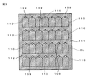
- FIG. 9 is an enlarged view of a main part of FIG. 8, and FIG. 10 is a plan view showing a state in which a laminated body of insulating substrates is punched into an assembly of a plurality of biosensors.
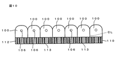
- FIG. 11 is a plan view of the biosensor.
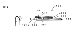
- 12 and 13 are diagrams for explaining a method of supplying a liquid sample to the cavity.
- FIG. 12 shows a state before the liquid sample is supplied into the cavity
- FIG. 13 shows a liquid in the cavity. It is a figure which shows the state in which the sample was supplied.
- FIGS. 1 to 3, 4, 6, and 8 indicate a cutting line CL when the biosensor 100 is singulated.
- FIG. 7, and FIG. 9 are enlarged views of essential parts showing regions surrounded by the cutting line CL in FIG. 4, FIG. 6, and FIG. 12 and 13 are cross-sectional views taken along line AA in FIG.
- the biosensor 100 of the present invention has substantially the same configuration except for the conventional biosensor 500 described with reference to FIG. 14 and the structure in the vicinity of the inlet 104a, and the working electrode 101 and the counter electrode 102 are used for detection. It has an electrode system including the electrode 103 and a reaction layer 107 containing an enzyme that reacts with the substance to be measured, and is used by being attached to a measuring instrument (not shown).
- a measurement target substance such as glucose contained in a liquid sample such as blood supplied to the cavity 104 provided on the distal end side of the biosensor 100 attached to the measuring instrument via the introduction port 104a, and the biosensor 100
- a liquid sample is obtained.
- the measurement target substance contained in is quantified.
- the biosensor 100 has insulating properties such as ceramic, glass, plastic, paper, biodegradable material, and polyethylene terephthalate.
- the electrode layer 110, the spacer layer 120, and the cover layer 130, which are made of a material, are formed by being laminated and bonded together with the end surfaces on the front end side where the liquid sample introduction port 104a is provided aligned.
- the electrode layer 110 (corresponding to the “first substrate” of the present invention), an electrode system including the working electrode 101, the counter electrode 102, and the detection electrode 103 is provided on the main surface on the slit 105 side.
- the cover layer 130 (corresponding to the “second substrate” of the present invention) has an air hole 106 communicating with the cavity 104, and a hydrophilizing agent is provided on the main surface forming the cavity 104.
- the spacer layer 120 (corresponding to the “spacer” of the present invention) is formed with a slit 105 for forming the cavity 104, and the electrode layer 110 and the electrode layer 110 so that the slit 105 is disposed on one end side of the working electrode 101 and the counter electrode 102. It is disposed between the cover layers 130.
- the cavity 104 is formed by the inner surface of the slit 105 and the main surface of the electrode layer 110 and the cover layer 130 on the slit 105 side, and is supplied with a liquid sample.
- the cavity 104 communicates with the outside.
- a liquid sample inlet 104 a is formed in the slit 105.
- the cover layer 130 is laminated on the spacer layer 120 so that the air hole 106 is disposed at the end of the cavity 104 opposite to the introduction port 104a.
- a notch 108 that is continuous with the introduction port 104a and is narrower than the introduction port 104 is provided.
- the notch 108 is formed at the center position in the width direction of the introduction port 104a. As shown in FIG.
- a reaction layer 107 containing an enzyme that reacts with a substance to be measured such as glucose contained in a liquid sample is provided on one end side of the working electrode 101 and the counter electrode 102. Then, the biosensor 100 is attached to a measuring instrument (not shown) by being inserted into a predetermined insertion port of the measuring instrument 2 from the rear end side.
- the electrode layer 110 is prepared as follows.
- an insulating substrate 111 made of an insulating material such as polyethylene terephthalate by screen printing or sputtering deposition.
- a conductive layer 112 made of a conductive material such as noble metal, carbon, copper, aluminum, titanium, ITO, or ZnO is formed.
- a through-hole 109 is formed on the cutting line CL at a position corresponding to the introduction port 104a of the biosensor 100 of the insulating substrate 111 (preparation step). Note that the conductive layer 112 may be formed after the through-hole 109 is formed in the insulating substrate 111.
- the conductive layer 112 is subjected to patterning by laser processing or photolithography to form a notch 113, whereby the working electrode 101, the counter electrode 102, and the detection electrode are formed.
- An electrode system including 103 is formed.
- the working electrode 101, the counter electrode 102, and the detection electrode 103 are arranged so that one end sides thereof are exposed to the cavity 104.
- the other end of each of the working electrode 101, the counter electrode 102, and the detection electrode 103 is an edge of the electrode layer 110 on the side opposite to the introduction port 104a, and the edge of the electrode layer 110 on which the spacer layer 120 is not laminated. To be formed.
- the insulating substrate 111 is formed into an aggregate substrate state by forming a plurality of electrode systems constituting the plurality of biosensors 100 on one main surface thereof. Yes. Then, as will be described later, after the spacer layer 120 and the cover layer 130 are laminated on the insulating substrate 111 (electrode layer 120), it is cut along the cutting line CL and cut into a predetermined shape, thereby forming individual biosensors 110. It is divided into pieces.
- the spacer layer 120 is laminated on the electrode layer 110 prepared as described above (first lamination step).
- the spacer layer 120 is formed of an insulating substrate 121 made of an insulating material such as polyethylene terephthalate, and the insulating substrate 121 has a slit 105 for forming the cavity 104. It is formed wider than the hole 109.
- the insulating substrate 121 includes a rear end portion of the biosensor 100 when separated into the biosensor 100, that is, a working electrode 101, a counter electrode 102, and a detection electrode 103, which are inserted into a measuring instrument. A position corresponding to the other end side of is cut out.
- the slit 105 is disposed on one end side of the working electrode 101, the counter electrode 102, and the detection electrode 103, and the through hole 109 is disposed on the inner side of the slit 105 in a plan view, so that the insulating substrate 121 (spacer layer 120). Is partially covered and laminated on one main surface of the insulating substrate 111 (electrode layer 110), whereby a cavity 104 to which a liquid sample is supplied is formed by the electrode layer 110 and the slit 105.
- the cavity 104 formed by laminating the spacer layer 120 on the electrode layer 110 is cleaned with plasma, and then the reaction layer 107 is formed in the cavity 104.
- plasma used in the plasma cleaning process
- various plasmas used in metal activation treatment by plasma such as oxygen plasma, nitrogen plasma, and argon plasma can be used. Plasma may be used.
- the reaction layer 107 is formed on one end side of the working electrode 101 and the counter electrode 102 and the detection electrode 103 exposed to the cavity 104 before the cover layer 130 is laminated on the spacer layer 120. It is formed by dropping a reagent containing a thickener such as carboxymethyl cellulose or gelatin, an enzyme, a mediator, an additive such as an amino acid or an organic acid. Further, in order to smoothly supply a liquid sample such as blood to the cavity 104, a hydrophilizing agent such as a surfactant or phospholipid is applied to the inner wall of the cavity 104.
- a hydrophilizing agent such as a surfactant or phospholipid is applied to the inner wall of the cavity 104.
- Enzymes include glucose oxidase, lactate oxidase, cholesterol oxidase, alcohol oxidase, sarcosine oxidase, fructosylamine oxidase, pyruvate oxidase, glucose dehydrogenase, lactate dehydrogenase, alcohol dehydrogenase, hydroxybutyrate dehydrogenase, cholesterol esterase, creatininase, creatinase DNA polymerase or the like can be used, and various sensors can be formed by selecting these enzymes according to the substance to be measured.
- glucose oxidase or glucose dehydrogenase can be used to form a glucose sensor that detects glucose in a liquid sample
- alcohol oxidase or alcohol dehydrogenase can be used to form an alcohol sensor that detects ethanol in a liquid sample
- a lactic acid sensor for detecting lactic acid in a liquid sample can be formed
- a total cholesterol sensor can be formed by using a mixture of cholesterol esterase and cholesterol oxidase.
- potassium ferricyanide As the mediator, potassium ferricyanide, ferrocene, ferrocene derivatives, benzoquinone, quinone derivatives, osmium complexes, ruthenium complexes and the like can be used.
- carboxymethyl cellulose carboxyethyl cellulose, polyethyleneimine, DEAE cellulose, dimethylaminoethyl dextran, carrageenan, sodium alginate, dextran and the like
- a surfactant such as Triton X100 (manufactured by Sigma Aldrich), Tween 20 (manufactured by Tokyo Chemical Industry Co., Ltd.), sodium bis (2-ethylhexyl) sulfosuccinate, or a phospholipid such as lecithin can be used.
- a buffer such as phosphoric acid may be provided in order to reduce the variation in ion concentration contained in the liquid sample.
- a cover layer 130 formed of a substrate made of an insulating material such as polyethylene terephthalate is stacked (second stacking step). As shown in FIGS. 10 and 11, the cover layer 130 is formed with an air hole 106 that communicates with the cavity 104 when laminated on the spacer layer 120. Further, the cover layer 130 covers the cavity 104 and is laminated on the spacer layer 120 so that the air holes 106 are arranged in positions different from the through holes 109 inside the slits 105 of the spacer layer 120 in plan view. Is done.
- the main surface of the cover layer 130 forming the cavity 104 is provided with a hydrophilizing agent such as a surfactant or phospholipid in order to smoothly supply a liquid sample such as blood to the cavity 104. .
- an assembly (laminated body) of biosensors 110 formed by laminating the cover layer 130 is cut into the biosensor 100 having a predetermined shape by being cut along the cutting line CL (cutting process). ).
- the assembly of biosensors 110 is punched along the cutting line CL, so that a plurality of biosensors 100 are first connected in the lateral direction. Aggregates are formed.
- the assembly of biosensors 100 connected in the horizontal direction is cut along the cutting line CL and separated into individual pieces of biosensors 100.
- the biosensor 100 is formed in which the introduction port 104a formed by the opening portion of the slit 105 formed in the tip surface portion of the spacer layer 120 is provided at the tip.
- the cutting line CL is set at a position passing through the through hole 109 and the slit 105, and an introduction port 104 a that communicates the cavity 104 with the outside is formed at the edge of the slit 105 after cutting.
- a notch 108 that is narrower than the introduction port 104a is formed continuously with the introduction port 104a.
- the biosensor 100 is formed for the purpose of quantifying glucose in blood, and FAD (flavin adenine dinucleotide) is used as an enzyme that specifically reacts with glucose as a measurement target substance.
- FAD flavin adenine dinucleotide
- a mediator that contains GDH (glucose dehydrogenase) hereinafter referred to as “FAD-GDH”), which is reduced by electrons generated by the reaction of glucose as a measurement object and FAD-GDH, and becomes a reducing substance
- the reaction layer 107 containing potassium ferricyanide is provided on one end side of the working electrode 101 and the counter electrode 102 exposed to the cavity 104.
- a liquid sample made of blood is brought into contact with the introduction port 104a formed at the tip thereof, whereby the liquid sample is sucked toward the air hole 106 due to capillary action and is brought into the cavity 104.
- a liquid sample is supplied.
- the electrode layer 110, the cover layer 130, and the spacer layer 120 are arranged with their end faces on the introduction port 104a side aligned.
- the electrode layer 110 includes a notch 108 that is continuous with the introduction port 104a and is narrower than the introduction port 104a, and a hydrophilizing agent is provided on the main surface of the cover layer 130 that forms the cavity 104. Therefore, as shown in FIG.
- a notch 108 that is continuous with the introduction port 104a is formed in the electrode layer 110. Since the notch 108 is formed narrower than the introduction port 104a, the side of the notch 108 viewed from the introduction port 104a is The electrode layer 110 in which the notch 108 is formed is maintained in a tubular shape by being sandwiched between the main surface of the portion that is lateral to the notch 108 and continuous with the introduction port 104a and the main surface of the cover layer 130 that faces the main surface. Has been. Therefore, as shown in FIG.
- the liquid sample that has entered the cavity 104 from the inlet 104a and the notch 108 is promoted to enter the cavity 104 by the hydrophilizing agent provided in the cover layer 130, and the notch It is fed into the cavity 104 by capillary action along the side tubular portion of 108.
- the reaction layer 107 when the reaction layer 107 is dissolved in the liquid sample supplied to the cavity 104, electrons are released by an enzymatic reaction between glucose and FAD-GDH, which are measurement target substances in the liquid sample, and ferricia is emitted by the emitted electrons.
- the ferric ion is reduced to produce ferrocyanide ion as a reducing substance.
- the reducing substance generated by the oxidation-reduction reaction caused by the reaction layer 107 dissolving in the liquid sample is electrochemically oxidized by applying a voltage between the working electrode 101 and the counter electrode 102 of the biosensor 100.
- glucose in the liquid sample is quantified in the measuring device.
- the notch 108 is connected to the introduction port 104a and formed narrower than the introduction port 104a. Therefore, even if the notch 108 connected to the introduction port 104a is formed, the cavity 104 communicated with the outside by the introduction port 104a is maintained in a tubular shape. Therefore, the liquid sample that has entered the cavity 104 from the inlet 104 a and the notch 108 is sucked toward the air hole 106 by capillary action while being promoted to enter the cavity 104 by the hydrophilizing agent provided in the cover layer 130. Is done. Therefore, the liquid sample brought into contact with the introduction port 104a from the front can be reliably supplied to the cavity 104.
- a reducing substance is generated when an enzyme that specifically reacts with a specific measurement target substance contained in the reaction layer 107 reacts with the measurement target substance contained in the liquid sample supplied to the cavity 104. Therefore, the measurement target substance can be quantified by measuring the oxidation current obtained by oxidizing the generated reducing substance by applying a voltage between the working electrode 101 and the counter electrode 102.
- the notch 108 is formed at the center position in the width direction of the inlet 104a, the liquid sample introduced from the inlet 104a and the notch 108 can enter the cavity 104 along both sides of the notch 108. . Therefore, the liquid sample can be efficiently supplied to the cavity 104.
- the biosensor 100 is manufactured as follows. That is, the electrode layer 110 provided with the through hole 109 is prepared, and the spacer layer 120 in which the slit 105 wider than the through hole 109 is formed is arranged so that the through hole 109 is disposed inside the slit 105 in a plan view.
- the electrode layer 110 is laminated.
- a cover layer 130 provided with a hydrophilizing agent on the main surface forming the cavity 104 is laminated on the spacer so that the air holes 106 are arranged at positions different from the through holes 109 inside the slit 105.
- the laminated body of the electrode layer 110, the cover layer 130, and the spacer layer 120 is cut along a cutting line CL set in advance at a position passing through the through-hole 109 and the slit 105, thereby obtaining a biomaterial having a predetermined shape.
- the sensor 100 cuts out.
- an introduction port 104a is formed at the edge of the slit 105 after cutting, and a notch 108 having a width narrower than that of the introduction port 104a is formed by the through-hole 109 after cutting so as to be connected to the introduction port 104a.
- the laminated body of the electrode layer 110 and the cover layer 130 in the aggregate substrate state and the spacer layer 120 is cut together to form a narrower width than the introduction port 104a continuously to the introduction port 104a.
- a plurality of biosensors 100 having the cutouts 108 can be efficiently manufactured collectively, so that productivity is high and the manufacturing cost of the biosensor 100 can be reduced.
- the present invention is not limited to the above-described embodiment, and various modifications other than those described above can be made without departing from the spirit of the present invention.
- the notch 108 is covered with the cover layer 130 (
- a hydrophilizing agent may be provided on the main surface of the electrode layer 110 (first substrate) where the cavity 104 is formed.
- an ethanol sensor, a lactic acid sensor, or the like may be formed by changing the combination of the enzyme and the mediator included in the reaction layer 107 of the biosensor 100 described above.
- the reaction layer 107 does not necessarily include a mediator.
- an oxidation current generated by oxidation of a reducing substance such as hydrogen peroxide or a reduced form of the enzyme generated by an enzyme reaction of a measurement target substance such as glucose is generated. Just measure.
- the biosensor 100 is formed in a bipolar electrode structure having the working electrode 101 and the counter electrode 102.
- the biosensor 100 is formed in a tripolar electrode structure by further providing a reference electrode. May be.
- a predetermined potential based on the counter electrode 102 may be applied to the working electrode 101 in a state where the counter electrode 102 is grounded and a reference potential is applied to the reference electrode by the voltage output unit.
- the detection electrode 103 is not necessarily provided. In this case, by applying a predetermined voltage between the working electrode 101 and the counter electrode 102, the current flowing between the working electrode 101 and the counter electrode 102 is monitored to confirm that the liquid sample is supplied to the cavity 104. What is necessary is just to detect.
- the cover layer 130 of the electrode layer 110, the spacer layer 120, and the cover layer 130 forming the biosensor 100 is formed of a transparent member so that it can be visually recognized that the liquid sample is supplied to the cavity 104. Is desirable.
- the configuration of the electrode system and the like provided in the biosensor 100 is not limited to the above example, and the configuration may be changed as appropriate according to the substance to be measured.
- the present invention can be applied to various biosensors and methods for manufacturing the biosensors.
Landscapes
- Life Sciences & Earth Sciences (AREA)
- Health & Medical Sciences (AREA)
- Chemical & Material Sciences (AREA)
- Physics & Mathematics (AREA)
- Molecular Biology (AREA)
- Hematology (AREA)
- Chemical Kinetics & Catalysis (AREA)
- Electrochemistry (AREA)
- Biophysics (AREA)
- Analytical Chemistry (AREA)
- Biochemistry (AREA)
- General Health & Medical Sciences (AREA)
- General Physics & Mathematics (AREA)
- Immunology (AREA)
- Pathology (AREA)
- Apparatus Associated With Microorganisms And Enzymes (AREA)
Abstract
Cette invention concerne un biocapteur capable d'introduire de manière fiable un échantillon liquide, qui est amené au contact d'un orifice d'introduction ménagé dans sa surface avant, dans une cavité. La présence d'une encoche (108) dans le prolongement de l'orifice d'introduction (104a), formée de façon à avoir une largeur plus étroite que l'orifice d'introduction (104a), permet de maintenir une cavité (104) qui communique avec l'extérieur par l'orifice d'introduction (104a) sous une forme tubulaire même si l'encoche (108) dans le prolongement de l'orifice d'introduction (104a) est formée. La perméation dans la cavité (104) de l'échantillon liquide, qui pénètre dans la cavité (104) à partir de l'orifice d'introduction (104a) et l'encoche (108), est favorisée par un agent hydrophilisant présent sur une couche de revêtement quand l'échantillon est attiré vers un trou d'air par capillarité. Par conséquent, un échantillon liquide, qui est amené au contact de l'orifice d'introduction 104a) ménagé dans la surface avant, peut être introduit de manière fiable dans la cavité (104).
Priority Applications (1)
| Application Number | Priority Date | Filing Date | Title |
|---|---|---|---|
| JP2014543165A JPWO2014064978A1 (ja) | 2012-10-22 | 2013-07-22 | バイオセンサおよびその製造方法 |
Applications Claiming Priority (2)
| Application Number | Priority Date | Filing Date | Title |
|---|---|---|---|
| JP2012232790 | 2012-10-22 | ||
| JP2012-232790 | 2012-10-22 |
Publications (1)
| Publication Number | Publication Date |
|---|---|
| WO2014064978A1 true WO2014064978A1 (fr) | 2014-05-01 |
Family
ID=50544359
Family Applications (1)
| Application Number | Title | Priority Date | Filing Date |
|---|---|---|---|
| PCT/JP2013/069759 Ceased WO2014064978A1 (fr) | 2012-10-22 | 2013-07-22 | Biocapteur et son procédé de fabrication |
Country Status (2)
| Country | Link |
|---|---|
| JP (1) | JPWO2014064978A1 (fr) |
| WO (1) | WO2014064978A1 (fr) |
Cited By (1)
| Publication number | Priority date | Publication date | Assignee | Title |
|---|---|---|---|---|
| WO2022044475A1 (fr) * | 2020-08-31 | 2022-03-03 | 住友化学株式会社 | Capteur électrochimique |
Citations (4)
| Publication number | Priority date | Publication date | Assignee | Title |
|---|---|---|---|---|
| JP2005523444A (ja) * | 2002-04-19 | 2005-08-04 | ノヴァ バイオメディカル コーポレイション | 改良型サンプルインレットを備えた使い捨てサブマイクロリットル量バイオセンサ |
| JP2007003361A (ja) * | 2005-06-24 | 2007-01-11 | Matsushita Electric Ind Co Ltd | バイオセンサ |
| JP2007147638A (ja) * | 1999-12-22 | 2007-06-14 | Roche Diagnostics Corp | 電流滴定バイオセンサーテストストリップ |
| JP2007524821A (ja) * | 2003-06-20 | 2007-08-30 | エフ ホフマン−ラ ロッシュ アクチェン ゲゼルシャフト | 張り出し試料受入チャンバーを持つ試験ストリップ |
Family Cites Families (6)
| Publication number | Priority date | Publication date | Assignee | Title |
|---|---|---|---|---|
| JP4916309B2 (ja) * | 2003-06-20 | 2012-04-11 | エフ ホフマン−ラ ロッシュ アクチェン ゲゼルシャフト | バイオセンサー試験ストリップ上の、コード情報のためのシステムおよび方法 |
| AU2006279579A1 (en) * | 2005-08-16 | 2007-02-22 | Home Diagnostics, Inc. | Method for test strip manufacturing and analysis |
| US8617366B2 (en) * | 2005-12-12 | 2013-12-31 | Nova Biomedical Corporation | Disposable urea sensor and system for determining creatinine and urea nitrogen-to-creatinine ratio in a single device |
| TWM297470U (en) * | 2006-02-21 | 2006-09-11 | Visgeneer Inc | Structures of biosensor strips |
| JP4674283B2 (ja) * | 2009-06-01 | 2011-04-20 | アークレイ株式会社 | 分析用具およびその製造方法 |
| JP5818275B2 (ja) * | 2011-03-29 | 2015-11-18 | 株式会社テクノメデイカ | バイオセンサ |
-
2013
- 2013-07-22 WO PCT/JP2013/069759 patent/WO2014064978A1/fr not_active Ceased
- 2013-07-22 JP JP2014543165A patent/JPWO2014064978A1/ja active Pending
Patent Citations (4)
| Publication number | Priority date | Publication date | Assignee | Title |
|---|---|---|---|---|
| JP2007147638A (ja) * | 1999-12-22 | 2007-06-14 | Roche Diagnostics Corp | 電流滴定バイオセンサーテストストリップ |
| JP2005523444A (ja) * | 2002-04-19 | 2005-08-04 | ノヴァ バイオメディカル コーポレイション | 改良型サンプルインレットを備えた使い捨てサブマイクロリットル量バイオセンサ |
| JP2007524821A (ja) * | 2003-06-20 | 2007-08-30 | エフ ホフマン−ラ ロッシュ アクチェン ゲゼルシャフト | 張り出し試料受入チャンバーを持つ試験ストリップ |
| JP2007003361A (ja) * | 2005-06-24 | 2007-01-11 | Matsushita Electric Ind Co Ltd | バイオセンサ |
Cited By (3)
| Publication number | Priority date | Publication date | Assignee | Title |
|---|---|---|---|---|
| WO2022044475A1 (fr) * | 2020-08-31 | 2022-03-03 | 住友化学株式会社 | Capteur électrochimique |
| JP2022040521A (ja) * | 2020-08-31 | 2022-03-11 | 住友化学株式会社 | 電気化学センサ |
| JP7516166B2 (ja) | 2020-08-31 | 2024-07-16 | 住友化学株式会社 | 電気化学センサおよび電気化学センサの製造方法 |
Also Published As
| Publication number | Publication date |
|---|---|
| JPWO2014064978A1 (ja) | 2016-09-08 |
Similar Documents
| Publication | Publication Date | Title |
|---|---|---|
| JP5708878B2 (ja) | バイオセンサおよびその製造方法 | |
| CN102778484B (zh) | 电化学电池和生产电化学电池的方法 | |
| US20150027886A1 (en) | Biosensor | |
| US20140246336A1 (en) | Substance determination method | |
| WO2013073073A1 (fr) | Biocapteur et procédé de production de biocapteur | |
| WO2014064978A1 (fr) | Biocapteur et son procédé de fabrication | |
| WO2014069070A1 (fr) | Biocapteur | |
| JP2014089097A (ja) | バイオセンサ | |
| JP5472066B2 (ja) | バイオセンサの製造方法 | |
| JP6197503B2 (ja) | バイオセンサ用電極原反、バイオセンサ用電極およびバイオセンサ | |
| WO2010134621A1 (fr) | Capteur tridimensionnel destiné à mesurer les composants du sang | |
| JP2013108791A (ja) | バイオセンサの製造方法およびバイオセンサ | |
| WO2015002184A1 (fr) | Biocapteur | |
| WO2011151953A1 (fr) | Procédé de mesure de substance | |
| JP2004156989A (ja) | バイオセンサ | |
| JP2015155841A (ja) | バイオセンサ | |
| JP2005010150A (ja) | バイオセンサ |
Legal Events
| Date | Code | Title | Description |
|---|---|---|---|
| 121 | Ep: the epo has been informed by wipo that ep was designated in this application |
Ref document number: 13849372 Country of ref document: EP Kind code of ref document: A1 |
|
| ENP | Entry into the national phase |
Ref document number: 2014543165 Country of ref document: JP Kind code of ref document: A |
|
| NENP | Non-entry into the national phase |
Ref country code: DE |
|
| 122 | Ep: pct application non-entry in european phase |
Ref document number: 13849372 Country of ref document: EP Kind code of ref document: A1 |