WO2014065013A1 - オイルシール - Google Patents
オイルシール Download PDFInfo
- Publication number
- WO2014065013A1 WO2014065013A1 PCT/JP2013/073748 JP2013073748W WO2014065013A1 WO 2014065013 A1 WO2014065013 A1 WO 2014065013A1 JP 2013073748 W JP2013073748 W JP 2013073748W WO 2014065013 A1 WO2014065013 A1 WO 2014065013A1
- Authority
- WO
- WIPO (PCT)
- Prior art keywords
- lip
- dust
- slinger
- peripheral surface
- bellows
- Prior art date
- Legal status (The legal status is an assumption and is not a legal conclusion. Google has not performed a legal analysis and makes no representation as to the accuracy of the status listed.)
- Ceased
Links
Images

Classifications
-
- F—MECHANICAL ENGINEERING; LIGHTING; HEATING; WEAPONS; BLASTING
- F16—ENGINEERING ELEMENTS AND UNITS; GENERAL MEASURES FOR PRODUCING AND MAINTAINING EFFECTIVE FUNCTIONING OF MACHINES OR INSTALLATIONS; THERMAL INSULATION IN GENERAL
- F16J—PISTONS; CYLINDERS; SEALINGS
- F16J15/00—Sealings
- F16J15/16—Sealings between relatively-moving surfaces
- F16J15/34—Sealings between relatively-moving surfaces with slip-ring pressed against a more or less radial face on one member
- F16J15/3436—Pressing means
- F16J15/3456—Pressing means without external means for pressing the ring against the face, e.g. slip-ring with a resilient lip
-
- F—MECHANICAL ENGINEERING; LIGHTING; HEATING; WEAPONS; BLASTING
- F16—ENGINEERING ELEMENTS AND UNITS; GENERAL MEASURES FOR PRODUCING AND MAINTAINING EFFECTIVE FUNCTIONING OF MACHINES OR INSTALLATIONS; THERMAL INSULATION IN GENERAL
- F16J—PISTONS; CYLINDERS; SEALINGS
- F16J15/00—Sealings
- F16J15/002—Sealings comprising at least two sealings in succession
-
- F—MECHANICAL ENGINEERING; LIGHTING; HEATING; WEAPONS; BLASTING
- F16—ENGINEERING ELEMENTS AND UNITS; GENERAL MEASURES FOR PRODUCING AND MAINTAINING EFFECTIVE FUNCTIONING OF MACHINES OR INSTALLATIONS; THERMAL INSULATION IN GENERAL
- F16J—PISTONS; CYLINDERS; SEALINGS
- F16J15/00—Sealings
- F16J15/16—Sealings between relatively-moving surfaces
- F16J15/32—Sealings between relatively-moving surfaces with elastic sealings, e.g. O-rings
-
- F—MECHANICAL ENGINEERING; LIGHTING; HEATING; WEAPONS; BLASTING
- F16—ENGINEERING ELEMENTS AND UNITS; GENERAL MEASURES FOR PRODUCING AND MAINTAINING EFFECTIVE FUNCTIONING OF MACHINES OR INSTALLATIONS; THERMAL INSULATION IN GENERAL
- F16C—SHAFTS; FLEXIBLE SHAFTS; ELEMENTS OR CRANKSHAFT MECHANISMS; ROTARY BODIES OTHER THAN GEARING ELEMENTS; BEARINGS
- F16C33/00—Parts of bearings; Special methods for making bearings or parts thereof
- F16C33/72—Sealings
- F16C33/76—Sealings of ball or roller bearings
- F16C33/78—Sealings of ball or roller bearings with a diaphragm, disc, or ring, with or without resilient members
- F16C33/7816—Details of the sealing or parts thereof, e.g. geometry, material
- F16C33/782—Details of the sealing or parts thereof, e.g. geometry, material of the sealing region
- F16C33/7823—Details of the sealing or parts thereof, e.g. geometry, material of the sealing region of sealing lips
-
- F—MECHANICAL ENGINEERING; LIGHTING; HEATING; WEAPONS; BLASTING
- F16—ENGINEERING ELEMENTS AND UNITS; GENERAL MEASURES FOR PRODUCING AND MAINTAINING EFFECTIVE FUNCTIONING OF MACHINES OR INSTALLATIONS; THERMAL INSULATION IN GENERAL
- F16J—PISTONS; CYLINDERS; SEALINGS
- F16J15/00—Sealings
- F16J15/16—Sealings between relatively-moving surfaces
- F16J15/164—Sealings between relatively-moving surfaces the sealing action depending on movements; pressure difference, temperature or presence of leaking fluid
-
- F—MECHANICAL ENGINEERING; LIGHTING; HEATING; WEAPONS; BLASTING
- F16—ENGINEERING ELEMENTS AND UNITS; GENERAL MEASURES FOR PRODUCING AND MAINTAINING EFFECTIVE FUNCTIONING OF MACHINES OR INSTALLATIONS; THERMAL INSULATION IN GENERAL
- F16J—PISTONS; CYLINDERS; SEALINGS
- F16J15/00—Sealings
- F16J15/16—Sealings between relatively-moving surfaces
- F16J15/32—Sealings between relatively-moving surfaces with elastic sealings, e.g. O-rings
- F16J15/3204—Sealings between relatively-moving surfaces with elastic sealings, e.g. O-rings with at least one lip
- F16J15/3232—Sealings between relatively-moving surfaces with elastic sealings, e.g. O-rings with at least one lip having two or more lips
-
- F—MECHANICAL ENGINEERING; LIGHTING; HEATING; WEAPONS; BLASTING
- F16—ENGINEERING ELEMENTS AND UNITS; GENERAL MEASURES FOR PRODUCING AND MAINTAINING EFFECTIVE FUNCTIONING OF MACHINES OR INSTALLATIONS; THERMAL INSULATION IN GENERAL
- F16J—PISTONS; CYLINDERS; SEALINGS
- F16J15/00—Sealings
- F16J15/16—Sealings between relatively-moving surfaces
- F16J15/32—Sealings between relatively-moving surfaces with elastic sealings, e.g. O-rings
- F16J15/3244—Sealings between relatively-moving surfaces with elastic sealings, e.g. O-rings with hydrodynamic pumping action
-
- F—MECHANICAL ENGINEERING; LIGHTING; HEATING; WEAPONS; BLASTING
- F16—ENGINEERING ELEMENTS AND UNITS; GENERAL MEASURES FOR PRODUCING AND MAINTAINING EFFECTIVE FUNCTIONING OF MACHINES OR INSTALLATIONS; THERMAL INSULATION IN GENERAL
- F16J—PISTONS; CYLINDERS; SEALINGS
- F16J15/00—Sealings
- F16J15/16—Sealings between relatively-moving surfaces
- F16J15/32—Sealings between relatively-moving surfaces with elastic sealings, e.g. O-rings
- F16J15/3248—Sealings between relatively-moving surfaces with elastic sealings, e.g. O-rings provided with casings or supports
- F16J15/3252—Sealings between relatively-moving surfaces with elastic sealings, e.g. O-rings provided with casings or supports with rigid casings or supports
- F16J15/3256—Sealings between relatively-moving surfaces with elastic sealings, e.g. O-rings provided with casings or supports with rigid casings or supports comprising two casing or support elements, one attached to each surface, e.g. cartridge or cassette seals
-
- F—MECHANICAL ENGINEERING; LIGHTING; HEATING; WEAPONS; BLASTING
- F16—ENGINEERING ELEMENTS AND UNITS; GENERAL MEASURES FOR PRODUCING AND MAINTAINING EFFECTIVE FUNCTIONING OF MACHINES OR INSTALLATIONS; THERMAL INSULATION IN GENERAL
- F16J—PISTONS; CYLINDERS; SEALINGS
- F16J15/00—Sealings
- F16J15/44—Free-space packings
- F16J15/447—Labyrinth packings
Definitions
- the present invention relates to an oil seal which is a kind of sealing device related to sealing technology.
- the oil seal of the present invention is used, for example, in the field related to automobiles (engines) or in the field of general industrial machinery.
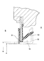
- an oil seal using a fabric 51 as a dust lip is known, and this oil seal is used, for example, for sealing around a crankshaft in the field of automobile engines (diesel engines). .
- the fabric 51 is set smaller than the outer diameter d 2 of the fabric sliding portion of the initial inner diameter (slinger 52 before insertion inside diameter) d 1 of the slinger 52, thereby the fabric 51 is tightened When the slinger 52 is inserted, the fabric 51 spreads along the slinger 52, and the contact width with the slinger 52 is secured.
- the fabric 51 is air permeable, it has the following advantages and disadvantages.
- advantage ⁇ When a situation occurs in which the pressure in the space 54 between the fabric 51 and the main lip 53 is reduced, the fabric 51 takes in (passes through) the air (atmosphere) outside the machine B and the pressure drop is suppressed. Therefore, it is possible to suppress the pressure of the space 54 between the fabric 51 and the main lip 53 from decreasing and the main lip 53 from sticking to the slinger 52 (advantage of taking in air of the fabric). Difficulties ...
- An air leak inspection may be performed at the time of shipment of the oil seal, and the inspection is generally performed by applying a positive pressure from the inside of the machine and measuring the amount of air leakage on the fabric 51 side.
- JP 10-115375 A Japanese Patent Laid-Open No. 7-208610
- the present invention can reduce sliding torque compared to the case of using a fabric as a dust lip, and achieves the same effect as the advantage of air intake of the fabric without using the fabric. It is another object of the present invention to provide an oil seal that can solve the problems caused by air release from the fabric.
- an oil seal according to claim 1 of the present invention comprises a combination of a lip seal member fixed to the inner periphery of a shaft hole of a housing and a slinger fixed to a rotating shaft inserted through the shaft hole, An oil seal that suppresses leakage of sealing fluid inside the machine and prevents dust outside the machine from entering the machine, and includes a dust cover together with the lip seal member and the slinger. And a cylindrical portion fitted to the rotary shaft and a flange portion formed so as to rise radially outward from the cylindrical portion, and radially outward on the outer end surface of the flange portion.
- the dust cover has a cylindrical portion that is fitted into the cylindrical portion of the slinger, and rises radially outward from the cylindrical portion.
- the radial portion is integrally provided with the formed radial direction portion, and the radial direction portion exerts a dust swinging action by a centrifugal force at the time of shaft rotation and a labyrinth sealing action by forming a minute gap between the lip seal member.
- a lip seal member disposed between the main lip and the dust cover, and a main lip that is slidably in close contact with an end surface of the flange portion of the slinger and seals the sealing fluid.
- a dust strip that is slidably in close contact with the outer peripheral surface of the cylindrical portion of the slinger and suppresses the intrusion of the dust, and the dust lip is made of a rubber-like elastic body that A first bellows portion that receives the internal pressure between the dust lip and the main lip at the outer peripheral surface and the atmospheric pressure outside the machine at the outer peripheral surface. And a second bellows portion receiving the internal pressure between the dust lip and the main lip at the inner peripheral surface, and a lip end slidably contacting the outer peripheral surface of the cylindrical portion of the slinger,
- the first bellows part is characterized in that the pressure receiving area is set larger than that of the second bellows part.
- the oil seal according to a second aspect of the present invention is the oil seal according to the first aspect, wherein the dust lip has a projection on a part of the circumference that contacts the outer peripheral surface of the cylindrical portion of the slinger.
- the dust lip has a projection on a part of the circumference that contacts the outer peripheral surface of the cylindrical portion of the slinger.
- the protrusion is interposed between the outer peripheral surface of the cylindrical part in the slinger and the inner peripheral surface of the second bellows part, and thereby the outer surface of the cylindrical part in the slinger It has a structure for reducing the contact surface pressure at the lip end of the dust lip.
- the dust lip is made of a rubber-like elastic body instead of a fabric, and the dust lip made of the rubber-like elastic body can be formed into a thin wall and easily elastically deformed.
- the tightening force is reduced while the tightening allowance is the same as that of the fabric.
- the dust lip is provided with the first bellows portion, the second bellows portion, and the lip end and has a bellows shape that is easily elastically deformed in the radial direction as a whole, the tightening force is greatly reduced. Therefore, it is possible to reduce the sliding torque of the dust lip from these facts.
- the dust lip is provided with the first bellows portion, the second bellows portion, and the lip end so as to be elastically deformed in the radial direction as a whole, and the first bellows portion is the first bellows portion. 2 Since the pressure receiving area is set larger than the bellows part, when the pressure in the space between the main lip and the dust lip decreases, the atmospheric pressure rises relatively, and the dust lip elastically deforms radially outward due to the pressure difference. (This is an image in which the bellows-shaped dust lip shrinks outward in the radial direction), and the lip end is separated (raised) from the outer peripheral surface of the cylindrical portion of the slinger.
- the difficulty caused by the air release of the fabric is solved as follows.
- the dust lip is provided with the first bellows portion, the second bellows portion, and the lip end so as to be elastically deformed in the radial direction as a whole, and the first bellows portion is the first bellows portion. 2 Since the pressure receiving area is set larger than the bellows part, when the pressure in the space between the main lip and the dust lip rises, the atmospheric pressure becomes relatively low and the dust lip is elastically deformed radially inward due to the pressure difference. (This is an image of a bellows-like dust lip extending radially inward.) The lip end is pressed against the outer peripheral surface of the cylindrical part of the slinger, and it is difficult to separate from the cylindrical part (it is difficult to lift). . Therefore, since the dust lip seals the pressure in the space between the main lip and the dust lip (air flow), if the oil seal is normal, no air leakage will be detected on the dust lip side. It is possible to perform a simple inspection with the threshold value set to zero.
- Dustrip has the original function of suppressing the entry of dust outside the machine into the machine, and in the present invention, dust is sealed as follows.
- the dust cover is provided together with the lip seal member and the slinger.
- This dust cover is integrally provided with a cylindrical portion that is fitted to the cylindrical portion of the slinger and a radial portion that is formed to rise radially outward from the cylindrical portion. It exhibits a dust swinging action by centrifugal force and a labyrinth sealing action by forming a minute gap between the lip seal members. Therefore, dust can be sealed by these actions.
- the dust lip is in a state where the lip end is in contact with the outer peripheral surface of the cylindrical portion of the slinger during normal operation. Therefore, dust can be sealed also by the sealing action of the dust lip.
- the dust lip it is conceivable to provide a part of the protrusion on the circumference that contacts the outer peripheral surface of the cylindrical portion of the slinger on the inner peripheral surface of the second bellows.
- the contact surface pressure of the lip end of the dust lip to the outer peripheral surface of the cylindrical portion in the slinger is reduced. Therefore, as described above, when the pressure in the space between the main lip and the dust lip decreases, the lip end is more easily separated from the outer peripheral surface of the cylindrical portion of the slinger (and more easily lifted), and thus the outside of the machine. Air (atmospheric pressure) easily flows.
- protrusion is provided in a part on the circumference, it does not hinder the inflow of air.
- the present invention has the following effects.
- the dust lip is not a fabric, but is formed of a rubber-like elastic body that can be formed into a thin wall and is easily elastically deformed, and the first bellows portion and the second bellows portion.
- the lip end is provided and the bellows is easy to elastically deform in the radial direction as a whole, the sliding torque of the dust lip can be reduced.
- the bellows dust lip operates in a direction away from the outer peripheral surface of the cylindrical portion of the slinger due to the pressure difference. (Atmospheric pressure) is introduced, so that the pressure in the space between the main lip and the dust lip can be prevented from being extremely reduced or negative pressure can be prevented, and the main lip is solid on the slinger. It is possible to suppress this.
- a dust cover is provided together with a lip seal member and a slinger, and this dust cover exerts a dust swinging action by centrifugal force during shaft rotation and a labyrinth sealing action by forming a minute gap between the dust cover and the lip seal member. Dustrip also exerts a sealing action by contact with the slinger, so that it is possible to suppress dust from outside the machine from entering the machine.
- the contact surface pressure of the dust lip against the slinger is reduced by providing a protrusion on the inner peripheral surface of the second bellows part, the pressure in the space between the main lip and the dust lip is reduced.
- the dust lip is more easily separated from the slinger. Accordingly, it is possible to further facilitate the inflow of air outside the machine (atmospheric pressure).
- FIG. 2 is a view in the direction of arrow C in FIG.
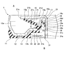
- FIG. 1 shows a cross section of a main part of an oil seal 1 according to an embodiment of the present invention
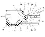
- FIG. 2 shows a state before the lip seal member 11 in the oil seal 1 is combined with a slinger 21.
- An oil seal 1 shown in FIG. 1 includes a lip seal member 11 that is fixed to the inner periphery of a shaft hole of a housing (not shown), and a slinger 21 that is fixed to a rotating shaft (not shown) inserted through the shaft hole.
- the sealing fluid in the machine A is prevented from leaking out of the machine B and the dust in the machine B is prevented from entering the machine A.
- a dust cover 31 is combined with the lip seal member 11 and the slinger 21.
- the slinger 21 is made of a metal material, and is formed by integrally forming a flange portion 21b radially outward at an inner end portion of the tubular portion 21a fitted to the outer peripheral surface of the rotating shaft.
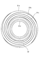
- a screw groove 22 (see FIG. 3) is provided on the machine-side end surface 21c of 21b to perform a pumping action radially outward.
- the screw groove 22 is a right four-thread screw, that is, a four-way groove that rotates clockwise from the inner side (inner diameter side) to the outer side (outer diameter side). 22 is provided in a range from the bent portion 21d to the tip portion 21e in the flange portion 21b.
- the lip seal member 11 includes an attachment ring 12 and a rubber-like elastic body 13 attached to the attachment ring 12.
- the mounting ring 12 is made of a metal material, and is formed by integrally forming a flange portion 12b radially inward at the outer end of the tubular portion 12a fitted to the inner peripheral surface of the shaft hole of the housing.
- the rubber-like elastic body 13 is slidably in close contact with the adherend rubber portion 14 attached to the mounting ring 12 and the machine end surface 21c of the flange portion 21b of the slinger 21 supported by the adherent rubber portion 14.
- a dust lip (bellows-shaped radial lip) 16 that is slidably in close contact with the outer peripheral surface of the portion 21a and suppresses the intrusion of dust is integrally provided.
- the main lip 15 is provided with its lip end 15a inclined inward and radially outward, and the lip end 15a is slid onto the machine end surface 21c of the flange portion 21b of the slinger 21. Closely movable.
- the dust lip 16 is provided on the inner peripheral side of the base end portion 15b of the main lip 15, and is inclined from the base end portion 16a to the inside of the machine and radially inward.
- the second bellows portion (inner peripheral side bellows portion) 16d and the lip end 16e provided at the tip of the second bellows portion 16d are integrally provided with a bellows shape (thin curved shape) having a V-shaped cross section as a whole.
- the lip end 16e is slidably in close contact with the outer peripheral surface of the cylindrical portion 21a of the slinger 21.
- the first bellows portion 16b has a tapered surface (conical surface) shape whose diameter is gradually reduced from the outside of the machine toward the inside of the machine with the above configuration. Further, the atmospheric pressure outside the machine B is received by the inner peripheral surface thereof, and the pressure (internal pressure) of the space 41 between the dust lip 16 and the main lip 15 is received by the outer peripheral surface thereof.
- the second bellows portion 16d has a tapered surface (conical surface) shape whose diameter is gradually reduced from the inside of the machine toward the outside of the machine with the above configuration. Further, the atmospheric pressure outside the machine B is received by the outer peripheral surface thereof, and the pressure (internal pressure) of the space 45 between the dust lip 16 and the main lip 15 is received by the inner peripheral surface thereof.
- the first bellows portion 16b Comparing the first bellows portion 16b and the second bellows portion 16d, the first bellows portion 16b has a larger diameter and a longer bellows length, so the first bellow portion 16b has a pressure receiving area than the second bellows portion 16d. It is set large.
- the reversing portion 16c is provided with an annular hook-shaped convex portion 17 toward the inside of the machine.
- protrusions (ribs) 18 are provided on the inner peripheral surface of the second bellows portion 16d in a part of the circumference (for example, two at a time in three equal parts).
- the protrusion 18 is slidably in contact with the outer peripheral surface of the cylindrical portion 21a of the slinger 21, and the protrusion 18 is an outer peripheral surface of the cylindrical portion 21a of the slinger 21 and the inner peripheral surface of the second bellows portion 16d.
- the dust cover 31 is made of a metal material, and an annular radial portion 31b is integrally formed radially outward at an outer end portion of the cylindrical portion 31a fitted to the outer peripheral surface of the cylindrical portion 21a of the slinger 21. It is a thing.
- the radial portion 31b exhibits a dust swinging action due to centrifugal force during rotation of the shaft, that is, a dust swinging effect of scattering dust attached to the surface of the radial portion 31b by centrifugal force during shaft rotation. Further, the radial portion 31b is opposed to the rubber-like elastic body 13 of the lip seal member 11 and forms a minute gap 32 with the rubber-like elastic body 13, thereby making it difficult for dust outside the machine B to enter.
- the minute gap 32 is composed of a combination of a radial gap 33 provided on the outer peripheral side of the radial portion 31b and an axial gap 34 provided on the inner side of the radial portion 31b, and is formed in an L-shaped cross section as a whole. ing.
- An annular radial portion 31c is also integrally formed at the inner end of the cylindrical portion 31a so as to extend radially outward.
- the oil seal 1 having the above-described configuration is used, for example, to seal around the axis of a crankshaft in an automobile engine, and suppresses leakage of the sealing fluid (oil) in the machine A to the outside B as described above. Prevents dust from outside B from entering machine A. Since the oil seal 1 has the above-described configuration, the following operational effects are exhibited.
- the dust lip 16 is made of a rubber-like elastic body instead of a fabric, and the dust lip 16 made of a rubber-like elastic body can be formed thin and easily elastically deformed. The tightening force is reduced while the tightening allowance is the same as that of the fabric. Further, the dust lip 16 is integrally formed with a base end portion 16a, a first bellows portion 16b, a reversing portion 16c, a second bellows portion 16 and a lip end 16e, and has a bellows shape that expands and contracts in the radial direction as a whole. The power is greatly reduced. Therefore, the sliding torque of the dust lip 16 can be reduced from these things.
- the screw groove 22 that performs a pumping action radially outward is provided on the machine outer end surface 21c of the flange portion 21b of the slinger 21.
- An excellent sealing effect is exhibited.
- the pressure in the space 41 between the main lip 15 and the dust lip 16 is caused by the pumping action of the thread groove 22 when the shaft rotates.
- the main lip 15 tends to stick to the slinger 21 easily.
- the dust lip 16 is integrally provided with the base end portion 16a, the first bellows portion 16b, the reversing portion 16c, the second bellows portion 16 and the lip end 16e as described above. Since the overall bellows shape expands and contracts in the radial direction and the pressure receiving area of the first bellows portion 16b is set larger than that of the second bellows portion 16d, the pressure in the space 41 between the main lip 15 and the dust lip 16 is reduced.
- the dust lip 16 Since the amount of lift outwardly in the radial direction by 16b exceeds this, the dust lip 16 is displaced radially outward as a whole, and as a result, the lip end 16e is the outer peripheral surface of the cylindrical portion 21a in the slinger 21 Will leave.) Accordingly, a gap is temporarily formed between the lip end 16e and the cylindrical portion 21a, and the air (atmospheric pressure) outside the machine B flows into the space 41 between the main lip 15 and the dust lip 16 via this gap. 15 and the dust lip 16 can be prevented from excessively reducing the pressure in the space 41 and the negative pressure being generated, thereby preventing the main lip 15 from sticking to the slinger 21. it can.
- the protrusion 18 on the circumference is provided on the inner peripheral surface of the second bellows portion 16d, and the contact surface pressure of the dust lip 16 with respect to the slinger 21 is reduced. This also makes it easier for the dust lip 16 to be separated from the slinger 21, thereby further facilitating the inflow of air (atmospheric pressure) outside the machine B.
- the protrusion 18 also has an effect of improving the followability of the dust strip 16 with respect to the eccentricity of the shaft.
- the screw groove 22 that performs the pumping action radially outward is provided on the machine outer end surface 21c of the flange portion 21b of the slinger 21.
- An excellent sealing effect is exerted on the hermetically sealed fluid, but when such a thread groove 22 is provided, an air flow path is formed through the thread groove 22, so that an air leak is produced when the oil seal 1 is shipped.
- the air flowing through the air flow path is detected as a leak.
- the dust lip 16 is integrally provided with the base end portion 16a, the first bellows portion 16b, the reversing portion 16c, the second bellows portion 16 and the lip end 16e as described above. Since the overall bellows shape expands and contracts in the radial direction and the pressure receiving area of the first bellows portion 16b is set larger than that of the second bellows portion 16d, the pressure in the space 41 between the main lip 15 and the dust lip 16 is reduced.
- the dust lip 16 When the pressure rises, the atmospheric pressure becomes relatively low, and the dust lip 16 is elastically deformed radially inward as a whole due to the pressure difference, and the lip end 16a is strongly pressed against the outer peripheral surface of the cylindrical portion 21 of the slinger 21 to form a cylindrical shape. It becomes difficult to leave the part 21a. Therefore, since the dust lip 16 seals the pressure (air flow) in the space 41 between the main lip 15 and the dust lip 16, when the oil seal 1 is normal, no air leak is detected on the dust lip 16 side. Therefore, a simple inspection can be performed in which the threshold value for air leakage is set to zero.
- the dust lip 16 has an original function of suppressing dust from outside the machine B from entering the machine A.
- the oil seal 1 having the above configuration seals the dust as follows.
- the dust cover 16 is provided together with the lip seal member 11 and the slinger 21, and the radial portion 16b of the dust cover 16 has a dust swinging action due to centrifugal force during shaft rotation and the lip seal member 11. Since the labyrinth sealing action by forming the minute gap 32 between the two is exhibited, dust can be sealed by these actions. Since the dust lip 16 is in a state where the lip end 16e is in contact with the outer peripheral surface of the cylindrical portion 21a of the slinger 21 at a normal time, dust can be sealed also by the sealing action of the dust lip 16.
- the dust cover 16 is a cylindrical portion (first cylindrical portion) 31a fitted to the outer peripheral surface of the cylindrical portion 21a of the slinger 21, and the outside of the cylindrical portion 31a.
- a radial part (first radial part) 31b provided radially outward from the end part and a radial part (second radial part) provided radially outward from the inboard end of the cylindrical part 31a
- a cylindrical portion (second cylindrical portion) 31d provided from the outer peripheral end portion of the radial direction portion 31b toward the outside of the machine and a machine end of the cylindrical portion 31d outward in the radial direction.
- a radial portion (third radial portion) 31e provided in the direction is integrally provided, and a minute gap 32 is formed between an axial gap 35 provided on the inner side of the radial portion 31e and an outer periphery of the cylindrical portion 31d.
- On the inner side of the radial gap 33 and the radial portion 31b provided on the side. Are those consisting of a combination of the axial gap 34 kicked.
- the other structure of the oil seal 1 of FIG. 4 is the same as that of the oil seal 1 of FIG.
- the dust lip 16 is entirely out of the radial direction by the atmospheric pressure that becomes a relatively high pressure when the pressure in the space 41 between the main lip 15 and the dust lip 16 decreases.
- the lip end 16e is separated from the outer peripheral surface of the cylindrical portion 21a in the slinger 21. This is because the rigidity of the dust strip 16 having a V-shaped cross section is somewhat high.
Landscapes
- Engineering & Computer Science (AREA)
- General Engineering & Computer Science (AREA)
- Mechanical Engineering (AREA)
- Physics & Mathematics (AREA)
- Fluid Mechanics (AREA)
- Sealing With Elastic Sealing Lips (AREA)
- Sealing Using Fluids, Sealing Without Contact, And Removal Of Oil (AREA)
Abstract
Description
利点・・・・
ファブリック51およびメインリップ53間の空間54の圧力が低下する状況が発生する場合、ファブリック51が機外Bのエア(大気)を取り込む(通過させる)ことにより圧力の低下が抑制される。したがってファブリック51およびメインリップ53間の空間54の圧力が低下してメインリップ53がスリンガー52にベタ当たりするのを抑制することができる(ファブリックのエア取り込みによる利点)。
難点・・・・
オイルシール出荷時にエアリーク検査を行なうことがあり、検査は一般に機内側から正圧をかけてファブリック51側でエア漏れ量を測定することにより行なわれる。この場合、上記従来技術ではファブリック51がエアを放出する(通過させる)ため、オイルシールが正常であっても漏れ量がゼロとならない。したがって漏れ許容値を設定したうえで検査を行なう必要があり、漏れしきい値をゼロ設定とする簡易な検査を行なうことができない(ファブリックのエア放出による難点)。
11 リップシール部材
12 取付環
12a,21a 筒状部
12b,21b フランジ部
13 ゴム状弾性体
14 被着ゴム部
15 メインリップ
15a,16e リップ端
15b,16a 基端部
16 ダストリップ
16b 第1ベロー部
16c 反転部
16d 第2ベロー部
17 凸部
18 突起
21 スリンガー
21c 機外側端面
21d 屈曲部
21e 先端部
22 ネジ溝
31 ダストカバー
31a,31d 筒状部
31b,31c,31e 径方向部
32 微小間隙
33 径方向間隙
34,35 軸方向間隙
A 機内
B 機外
Claims (2)
- ハウジングの軸孔内周に固定されるリップシール部材および前記軸孔に挿通する回転軸に固定されるスリンガーの組み合わせよりなり、機内の密封流体が機外へ漏洩するのを抑制するとともに機外のダストが機内へ侵入するのを抑制するオイルシールであって、
前記リップシール部材および前記スリンガーとともにダストカバーを備え、
前記スリンガーは、前記回転軸に嵌合される筒状部と前記筒状部から径方向外方へ向け立ち上げ形成されたフランジ部とを一体に備え、前記フランジ部の機外側端面に径方向外方へ向けてポンピング作用をなすネジ溝を備え、
前記ダストカバーは、前記スリンガーの筒状部に嵌合される円筒部と前記円筒部から径方向外方へ向け立ち上げ形成された径方向部とを一体に備え、前記径方向部は、軸回転時の遠心力によるダスト振り切り作用および前記リップシール部材との間に微小間隙を形成することによるラビリンスシール作用を発揮する構造を備え、
前記リップシール部材は、前記スリンガーにおけるフランジ部の機外側端面に摺動可能に密接して前記密封流体をシールするメインリップと、前記メインリップおよび前記ダストカバー間に配置されるとともに前記スリンガーにおける筒状部の外周面に摺動可能に密接して前記ダストの侵入を抑制するダストリップとを備え、
前記ダストリップは、ゴム状弾性体よりなり、機外の大気圧を内周面で受けるとともに当該ダストリップおよび前記メインリップ間の内圧を外周面で受ける第1ベロー部と、機外の大気圧を外周面で受けるとともに当該ダストリップおよび前記メインリップ間の内圧を内周面で受ける第2ベロー部と、前記スリンガーにおける筒状部の外周面に摺動可能に密接するリップ端とを一体に備え、さらに前記第1ベロー部のほうが前記第2ベロー部よりも受圧面積が大きく設定されていることを特徴とするオイルシール。 - 請求項1記載のオイルシールにおいて、
前記ダストリップは、前記スリンガーにおける筒状部の外周面に接触する円周上一部の突起を前記第2ベロー部の内周面に備え、前記突起が前記スリンガーにおける筒状部の外周面および前記第2ベロー部の内周面間に介在することにより前記スリンガーにおける筒状部の外周面に対する前記ダストリップのリップ端の接触面圧を低減する構造を備えることを特徴とするオイルシール。
Priority Applications (4)
| Application Number | Priority Date | Filing Date | Title |
|---|---|---|---|
| EP13848284.9A EP2913565B1 (en) | 2012-10-23 | 2013-09-04 | Oil seal |
| KR1020157012127A KR102077277B1 (ko) | 2012-10-23 | 2013-09-04 | 오일 시일 |
| CN201380054006.0A CN104718404B (zh) | 2012-10-23 | 2013-09-04 | 油封件 |
| US14/437,437 US9618117B2 (en) | 2012-10-23 | 2013-09-04 | Oil seal |
Applications Claiming Priority (2)
| Application Number | Priority Date | Filing Date | Title |
|---|---|---|---|
| JP2012-233636 | 2012-10-23 | ||
| JP2012233636A JP5964201B2 (ja) | 2012-10-23 | 2012-10-23 | オイルシール |
Publications (1)
| Publication Number | Publication Date |
|---|---|
| WO2014065013A1 true WO2014065013A1 (ja) | 2014-05-01 |
Family
ID=50544394
Family Applications (1)
| Application Number | Title | Priority Date | Filing Date |
|---|---|---|---|
| PCT/JP2013/073748 Ceased WO2014065013A1 (ja) | 2012-10-23 | 2013-09-04 | オイルシール |
Country Status (6)
| Country | Link |
|---|---|
| US (1) | US9618117B2 (ja) |
| EP (1) | EP2913565B1 (ja) |
| JP (1) | JP5964201B2 (ja) |
| KR (1) | KR102077277B1 (ja) |
| CN (1) | CN104718404B (ja) |
| WO (1) | WO2014065013A1 (ja) |
Cited By (3)
| Publication number | Priority date | Publication date | Assignee | Title |
|---|---|---|---|---|
| US20160348726A1 (en) * | 2015-05-29 | 2016-12-01 | Aktiebolaget Skf | Bearing seal and use thereof |
| CN107208802A (zh) * | 2015-04-02 | 2017-09-26 | Nok株式会社 | 密封装置 |
| CN107676484A (zh) * | 2014-06-10 | 2018-02-09 | Nok株式会社 | 密封装置 |
Families Citing this family (16)
| Publication number | Priority date | Publication date | Assignee | Title |
|---|---|---|---|---|
| WO2016147835A1 (ja) * | 2015-03-18 | 2016-09-22 | Nok株式会社 | 密封装置 |
| CN108138965B (zh) * | 2015-11-30 | 2019-01-11 | Nok株式会社 | 密封装置 |
| WO2017094597A1 (ja) * | 2015-11-30 | 2017-06-08 | Nok株式会社 | 密封装置 |
| JP6782600B2 (ja) * | 2016-10-04 | 2020-11-11 | ナブテスコ株式会社 | シール及びシール機構 |
| US10240678B2 (en) | 2016-10-18 | 2019-03-26 | Tenneco Inc. | Radial shaft seal assembly with axially adaptive debris exclusion face lip and oil seal face lip |
| WO2018117100A1 (ja) * | 2016-12-21 | 2018-06-28 | Nok株式会社 | 密封装置 |
| KR102377227B1 (ko) | 2017-03-09 | 2022-03-22 | 존슨 컨트롤스 테크놀러지 컴퍼니 | 백투백 베어링 밀봉 시스템 |
| EP3633245B1 (en) * | 2017-06-02 | 2022-04-20 | Nok Corporation | Sealing device |
| CN109322999B (zh) * | 2017-08-01 | 2022-10-28 | 舍弗勒技术股份两合公司 | 密封装置及其制造方法 |
| KR102239334B1 (ko) | 2019-04-10 | 2021-04-21 | 평화오일씰공업 주식회사 | 슬링거-오일 씰 조합체 |
| JP7530705B2 (ja) * | 2019-04-17 | 2024-08-08 | ナブテスコ株式会社 | シール構造 |
| IT202000009139A1 (it) * | 2020-04-28 | 2021-10-28 | Skf Ab | Dispositivo di tenuta includente un labbro flessibile con compensazione dinamica delle variazioni di interferenza |
| EP3991918A1 (de) * | 2020-10-28 | 2022-05-04 | Hilti Aktiengesellschaft | Dichtgeometrie für eine mobile werkzeugmaschine |
| IT202100004538A1 (it) * | 2021-02-26 | 2022-08-26 | Freudenberg Sealing Tech S A S Di Externa Italia S R L U | Gruppo di tenuta per una ruota motorizzata di un veicolo |
| CN113931934A (zh) * | 2021-11-25 | 2022-01-14 | 湖北新火炬科技有限公司 | 一种低力矩密封结构的轮毂轴承单元 |
| CN119070531B (zh) * | 2024-11-06 | 2025-05-02 | 苏州朗高电机科技股份有限公司 | 一种防涉水的密封电机结构 |
Citations (6)
| Publication number | Priority date | Publication date | Assignee | Title |
|---|---|---|---|---|
| JPH0427262U (ja) * | 1990-06-26 | 1992-03-04 | ||
| JPH07208610A (ja) | 1994-01-26 | 1995-08-11 | Isuzu Motors Ltd | オイルシール |
| JPH08254213A (ja) * | 1995-03-17 | 1996-10-01 | Koyo Seiko Co Ltd | ウォ−タポンプ用軸受の密封装置 |
| JPH08303604A (ja) * | 1995-05-02 | 1996-11-22 | Kiipaa Kk | オイルシール |
| JPH0942300A (ja) * | 1995-08-01 | 1997-02-10 | Koyo Seiko Co Ltd | 密封装置 |
| JPH10115375A (ja) | 1996-10-09 | 1998-05-06 | Keeper Co Ltd | オイルシール装置 |
Family Cites Families (19)
| Publication number | Priority date | Publication date | Assignee | Title |
|---|---|---|---|---|
| US3682488A (en) * | 1969-09-10 | 1972-08-08 | Nippon Oil Seal Ind Co Ltd | Sealing device |
| JPH0722532Y2 (ja) * | 1988-06-14 | 1995-05-24 | エヌオーケー株式会社 | 密封装置 |
| DE4110154C2 (de) * | 1991-03-27 | 1996-08-29 | Bruss Dichtungstechnik | Wellendichtring |
| US7066467B2 (en) * | 2000-12-28 | 2006-06-27 | Koyo Seiko Co., Ltd. | Sealing device for water pump bearings |
| JP2003287142A (ja) | 2002-03-29 | 2003-10-10 | Nok Corp | 密封装置 |
| JPWO2004020879A1 (ja) | 2002-08-27 | 2005-12-15 | 日本精工株式会社 | ステアリングシャフト用ダストカバー |
| US20050184469A1 (en) * | 2004-02-20 | 2005-08-25 | Kazuo Ishii | Bearing seal |
| US7464939B2 (en) | 2004-03-23 | 2008-12-16 | Nok Corporation | Sealing device with rotation detecting element |
| CN100449183C (zh) | 2004-03-23 | 2009-01-07 | Nok株式会社 | 带转动检测元件的密封装置 |
| DE602005020219D1 (de) * | 2004-07-09 | 2010-05-12 | Freudenberg Carl Kg | Wellendichtring |
| JP4739745B2 (ja) | 2004-12-21 | 2011-08-03 | Nok株式会社 | 遮音シール付き密封装置 |
| JP5110250B2 (ja) | 2006-02-06 | 2012-12-26 | Nok株式会社 | オイルシール |
| JP5170365B2 (ja) | 2007-02-16 | 2013-03-27 | Nok株式会社 | 密封装置 |
| JP5170366B2 (ja) * | 2007-02-22 | 2013-03-27 | Nok株式会社 | 密封装置 |
| JP2009074602A (ja) | 2007-09-20 | 2009-04-09 | Nok Corp | オイルシール |
| JPWO2009130933A1 (ja) * | 2008-04-25 | 2011-08-11 | Nok株式会社 | 密封装置 |
| CN102046497B (zh) * | 2008-05-27 | 2014-09-24 | 日本精工株式会社 | 滚动轴承 |
| CN201412512Y (zh) | 2009-03-25 | 2010-02-24 | 昆山茂顺密封件工业有限公司 | 复合式油封 |
| JP6054135B2 (ja) * | 2012-10-23 | 2016-12-27 | Nok株式会社 | オイルシール |
-
2012
- 2012-10-23 JP JP2012233636A patent/JP5964201B2/ja not_active Expired - Fee Related
-
2013
- 2013-09-04 EP EP13848284.9A patent/EP2913565B1/en not_active Not-in-force
- 2013-09-04 CN CN201380054006.0A patent/CN104718404B/zh not_active Expired - Fee Related
- 2013-09-04 WO PCT/JP2013/073748 patent/WO2014065013A1/ja not_active Ceased
- 2013-09-04 US US14/437,437 patent/US9618117B2/en not_active Expired - Fee Related
- 2013-09-04 KR KR1020157012127A patent/KR102077277B1/ko not_active Expired - Fee Related
Patent Citations (6)
| Publication number | Priority date | Publication date | Assignee | Title |
|---|---|---|---|---|
| JPH0427262U (ja) * | 1990-06-26 | 1992-03-04 | ||
| JPH07208610A (ja) | 1994-01-26 | 1995-08-11 | Isuzu Motors Ltd | オイルシール |
| JPH08254213A (ja) * | 1995-03-17 | 1996-10-01 | Koyo Seiko Co Ltd | ウォ−タポンプ用軸受の密封装置 |
| JPH08303604A (ja) * | 1995-05-02 | 1996-11-22 | Kiipaa Kk | オイルシール |
| JPH0942300A (ja) * | 1995-08-01 | 1997-02-10 | Koyo Seiko Co Ltd | 密封装置 |
| JPH10115375A (ja) | 1996-10-09 | 1998-05-06 | Keeper Co Ltd | オイルシール装置 |
Non-Patent Citations (1)
| Title |
|---|
| See also references of EP2913565A4 * |
Cited By (7)
| Publication number | Priority date | Publication date | Assignee | Title |
|---|---|---|---|---|
| CN107676484A (zh) * | 2014-06-10 | 2018-02-09 | Nok株式会社 | 密封装置 |
| US10352450B2 (en) | 2014-06-10 | 2019-07-16 | Nok Corporation | Sealing device |
| US10683935B2 (en) | 2014-06-10 | 2020-06-16 | Nok Corporation | Sealing device |
| CN107208802A (zh) * | 2015-04-02 | 2017-09-26 | Nok株式会社 | 密封装置 |
| US10544865B2 (en) | 2015-04-02 | 2020-01-28 | Nok Corporation | Sealing device |
| US20160348726A1 (en) * | 2015-05-29 | 2016-12-01 | Aktiebolaget Skf | Bearing seal and use thereof |
| US9897147B2 (en) * | 2015-05-29 | 2018-02-20 | Aktiebolaget Skf | Bearing seal and use thereof |
Also Published As
| Publication number | Publication date |
|---|---|
| US20150276059A1 (en) | 2015-10-01 |
| JP2014084933A (ja) | 2014-05-12 |
| EP2913565A1 (en) | 2015-09-02 |
| CN104718404A (zh) | 2015-06-17 |
| KR102077277B1 (ko) | 2020-02-13 |
| JP5964201B2 (ja) | 2016-08-03 |
| EP2913565B1 (en) | 2017-01-25 |
| KR20150074028A (ko) | 2015-07-01 |
| EP2913565A4 (en) | 2015-11-18 |
| CN104718404B (zh) | 2017-04-26 |
| US9618117B2 (en) | 2017-04-11 |
Similar Documents
| Publication | Publication Date | Title |
|---|---|---|
| JP5964201B2 (ja) | オイルシール | |
| JP6054135B2 (ja) | オイルシール | |
| JP6445085B2 (ja) | 密封装置 | |
| JP6000845B2 (ja) | 密封装置 | |
| WO2017104278A1 (ja) | 密封装置 | |
| JP5989493B2 (ja) | オイルシール | |
| WO2006132121A1 (ja) | 密封装置 | |
| JP6650742B2 (ja) | 密封装置 | |
| JP6378548B2 (ja) | 密封装置 | |
| JP7465632B2 (ja) | 密封装置 | |
| JPWO2020080408A1 (ja) | 密封装置 | |
| JP6545486B2 (ja) | 密封装置 | |
| JP4193299B2 (ja) | 密封装置 | |
| JPH0810713Y2 (ja) | 密封装置 | |
| JP7118782B2 (ja) | 密封装置 | |
| JP3111991U (ja) | シール装置 | |
| JP6368152B2 (ja) | 密封装置 | |
| WO2017098985A1 (ja) | 密封装置 |
Legal Events
| Date | Code | Title | Description |
|---|---|---|---|
| 121 | Ep: the epo has been informed by wipo that ep was designated in this application |
Ref document number: 13848284 Country of ref document: EP Kind code of ref document: A1 |
|
| WWE | Wipo information: entry into national phase |
Ref document number: 14437437 Country of ref document: US |
|
| REEP | Request for entry into the european phase |
Ref document number: 2013848284 Country of ref document: EP |
|
| WWE | Wipo information: entry into national phase |
Ref document number: 2013848284 Country of ref document: EP |
|
| NENP | Non-entry into the national phase |
Ref country code: DE |
|
| ENP | Entry into the national phase |
Ref document number: 20157012127 Country of ref document: KR Kind code of ref document: A |