WO2014065247A1 - Procédé de fabrication de matériau de surface transparent ayant une couche adhésive et dispositif de production de matériau de surface transparent ayant une couche adhésive - Google Patents
Procédé de fabrication de matériau de surface transparent ayant une couche adhésive et dispositif de production de matériau de surface transparent ayant une couche adhésive Download PDFInfo
- Publication number
- WO2014065247A1 WO2014065247A1 PCT/JP2013/078504 JP2013078504W WO2014065247A1 WO 2014065247 A1 WO2014065247 A1 WO 2014065247A1 JP 2013078504 W JP2013078504 W JP 2013078504W WO 2014065247 A1 WO2014065247 A1 WO 2014065247A1
- Authority
- WO
- WIPO (PCT)
- Prior art keywords
- film
- protective film
- layer
- adhesive layer
- transparent surface
- Prior art date
- Legal status (The legal status is an assumption and is not a legal conclusion. Google has not performed a legal analysis and makes no representation as to the accuracy of the status listed.)
- Ceased
Links
Images























Classifications
-
- B—PERFORMING OPERATIONS; TRANSPORTING
- B32—LAYERED PRODUCTS
- B32B—LAYERED PRODUCTS, i.e. PRODUCTS BUILT-UP OF STRATA OF FLAT OR NON-FLAT, e.g. CELLULAR OR HONEYCOMB, FORM
- B32B27/00—Layered products comprising a layer of synthetic resin
- B32B27/32—Layered products comprising a layer of synthetic resin comprising polyolefins
-
- B—PERFORMING OPERATIONS; TRANSPORTING
- B32—LAYERED PRODUCTS
- B32B—LAYERED PRODUCTS, i.e. PRODUCTS BUILT-UP OF STRATA OF FLAT OR NON-FLAT, e.g. CELLULAR OR HONEYCOMB, FORM
- B32B27/00—Layered products comprising a layer of synthetic resin
- B32B27/06—Layered products comprising a layer of synthetic resin as the main or only constituent of a layer, which is next to another layer of the same or of a different material
- B32B27/08—Layered products comprising a layer of synthetic resin as the main or only constituent of a layer, which is next to another layer of the same or of a different material of synthetic resin
-
- B—PERFORMING OPERATIONS; TRANSPORTING
- B32—LAYERED PRODUCTS
- B32B—LAYERED PRODUCTS, i.e. PRODUCTS BUILT-UP OF STRATA OF FLAT OR NON-FLAT, e.g. CELLULAR OR HONEYCOMB, FORM
- B32B27/00—Layered products comprising a layer of synthetic resin
- B32B27/16—Layered products comprising a layer of synthetic resin specially treated, e.g. irradiated
-
- B—PERFORMING OPERATIONS; TRANSPORTING
- B32—LAYERED PRODUCTS
- B32B—LAYERED PRODUCTS, i.e. PRODUCTS BUILT-UP OF STRATA OF FLAT OR NON-FLAT, e.g. CELLULAR OR HONEYCOMB, FORM
- B32B27/00—Layered products comprising a layer of synthetic resin
- B32B27/30—Layered products comprising a layer of synthetic resin comprising vinyl (co)polymers; comprising acrylic (co)polymers
- B32B27/308—Layered products comprising a layer of synthetic resin comprising vinyl (co)polymers; comprising acrylic (co)polymers comprising acrylic (co)polymers
-
- B—PERFORMING OPERATIONS; TRANSPORTING
- B32—LAYERED PRODUCTS
- B32B—LAYERED PRODUCTS, i.e. PRODUCTS BUILT-UP OF STRATA OF FLAT OR NON-FLAT, e.g. CELLULAR OR HONEYCOMB, FORM
- B32B27/00—Layered products comprising a layer of synthetic resin
- B32B27/34—Layered products comprising a layer of synthetic resin comprising polyamides
-
- B—PERFORMING OPERATIONS; TRANSPORTING
- B32—LAYERED PRODUCTS
- B32B—LAYERED PRODUCTS, i.e. PRODUCTS BUILT-UP OF STRATA OF FLAT OR NON-FLAT, e.g. CELLULAR OR HONEYCOMB, FORM
- B32B27/00—Layered products comprising a layer of synthetic resin
- B32B27/36—Layered products comprising a layer of synthetic resin comprising polyesters
-
- B—PERFORMING OPERATIONS; TRANSPORTING
- B32—LAYERED PRODUCTS
- B32B—LAYERED PRODUCTS, i.e. PRODUCTS BUILT-UP OF STRATA OF FLAT OR NON-FLAT, e.g. CELLULAR OR HONEYCOMB, FORM
- B32B27/00—Layered products comprising a layer of synthetic resin
- B32B27/36—Layered products comprising a layer of synthetic resin comprising polyesters
- B32B27/365—Layered products comprising a layer of synthetic resin comprising polyesters comprising polycarbonates
-
- B—PERFORMING OPERATIONS; TRANSPORTING
- B32—LAYERED PRODUCTS
- B32B—LAYERED PRODUCTS, i.e. PRODUCTS BUILT-UP OF STRATA OF FLAT OR NON-FLAT, e.g. CELLULAR OR HONEYCOMB, FORM
- B32B2307/00—Properties of the layers or laminate
- B32B2307/40—Properties of the layers or laminate having particular optical properties
- B32B2307/402—Coloured
-
- B—PERFORMING OPERATIONS; TRANSPORTING
- B32—LAYERED PRODUCTS
- B32B—LAYERED PRODUCTS, i.e. PRODUCTS BUILT-UP OF STRATA OF FLAT OR NON-FLAT, e.g. CELLULAR OR HONEYCOMB, FORM
- B32B2307/00—Properties of the layers or laminate
- B32B2307/40—Properties of the layers or laminate having particular optical properties
- B32B2307/412—Transparent
-
- B—PERFORMING OPERATIONS; TRANSPORTING
- B32—LAYERED PRODUCTS
- B32B—LAYERED PRODUCTS, i.e. PRODUCTS BUILT-UP OF STRATA OF FLAT OR NON-FLAT, e.g. CELLULAR OR HONEYCOMB, FORM
- B32B2457/00—Electrical equipment
- B32B2457/20—Displays, e.g. liquid crystal displays, plasma displays
-
- B—PERFORMING OPERATIONS; TRANSPORTING
- B32—LAYERED PRODUCTS
- B32B—LAYERED PRODUCTS, i.e. PRODUCTS BUILT-UP OF STRATA OF FLAT OR NON-FLAT, e.g. CELLULAR OR HONEYCOMB, FORM
- B32B2457/00—Electrical equipment
- B32B2457/20—Displays, e.g. liquid crystal displays, plasma displays
- B32B2457/208—Touch screens
Definitions
- the present invention relates to a method for producing a transparent surface material with an adhesive layer and an apparatus for producing a transparent surface material with an adhesive layer.
- a display device in which a display panel is protected by a transparent surface material is known.
- the display panel and a transparent surface material with an adhesive layer in which an adhesive layer is formed on the surface of the transparent surface material are pasted so that the adhesive layer is in contact with the display panel.
- a combined display device is known (see, for example, Patent Document 1).
- Patent Document 1 a transparent surface material with an adhesive layer is produced by a batch process in units of face materials, and a method for producing a transparent surface material with an adhesive layer superior in productivity than the batch process has been demanded.
- the present invention has been made in view of such circumstances, and provides a method for producing a transparent surface material with an adhesive layer having high productivity. Moreover, the manufacturing apparatus of the transparent surface material with an adhesion layer which can manufacture the transparent surface material with an adhesion layer efficiently is provided.
- the manufacturing method of the transparent surface material with the adhesion layer which concerns on 1 aspect of this invention laminates
- pressure-sensitive adhesive in the present specification, including the precursor material of the pressure-sensitive adhesive, unless otherwise specified.
- a step of coating a part of the pressure-sensitive adhesive to form a semi-cured layer, forming a protective film original film with a semi-cured layer, and a plurality of the frame-shaped films While transporting the transparent face material, the frame-like frame of each transparent face material A step of laminating the surface on which the rum is laminated and the surface on which the semi-cured layer of the protective film original fabric with the semi-cured layer is formed; and further curing the bonded semi-cured layer
- the manufacturing apparatus of the transparent surface material with the adhesion layer which concerns on 1 aspect of this invention is provided in the conveyance part which can convey a some transparent surface material continuously, and a part of said conveyance part, and is conveyed.
- a frame-like film is laminated on the upper surface of each of the transparent face materials, and a pressure-sensitive adhesive is applied to the first bonding portion that forms the transparent face material with the frame-like film and one surface of the belt-shaped protective film original fabric.
- the 1st hardening part which makes the semi-hardened layer by hardening the pressure sensitive adhesive, and forms the protective film original fabric with a semi-hardened layer, and the 1st pasting part on the conveyance path of the conveyance part
- the semi-cured layer of the protective film original fabric with the semi-cured layer and the surface on the side where the frame-shaped film of each transparent surface material is laminated while transporting a plurality of the transparent surface materials with the frame-shaped film provided later A second bonding part for bonding the formed side surface and the half after the bonding Comprising a second cured portion curing the layer, the.
- Another method for producing a transparent surface material with an adhesive layer includes a plurality of transparent surface materials, a strip-shaped protective film original fabric, and an adhesive formed along the extending direction of the protective film raw fabric A step of continuously laminating the plurality of transparent surface materials and the protective film original fabric via the adhesive layer, respectively, while transporting each of the laminates of the layers, and at least the protective film original fabric, Cutting in a direction intersecting with the extending direction of the protective film original fabric.
- the manufacturing method of the transparent surface material with the adhesion layer which concerns on another aspect of this invention can also be made into the following methods.
- the manufacturing method of the transparent surface material with the adhesion layer which concerns on another aspect of this invention laminates
- a step of forming a film original fabric, a surface on which the frame-shaped film of each transparent surface material is laminated while conveying a plurality of transparent surface materials with the frame-shaped film, and the protective film original material with the adhesive layer A step of bonding the surface on which the pressure-sensitive adhesive layer is formed in a reduced-pressure atmosphere, and a step of cutting the bonded pressure-sensitive adhesive layer and the protective film original fabric on the frame-shaped film.
- the pressure-sensitive adhesive is a photocurable resin, and the curing may be performed by light irradiation.
- the semi-cured layer may be hardened more than the surface layer.
- the second pressure-sensitive adhesive having a slower curing rate than the pressure-sensitive adhesive is formed on the pressure-sensitive adhesive layer before the semi-cured layer is formed. It is good also as providing the process of apply
- the original protective film has a light-transmitting property, and during the curing to form the semi-cured layer, the original protective film is interposed
- the pressure-sensitive adhesive may be irradiated with light.
- the manufacturing apparatus of the transparent surface material with the adhesion layer which concerns on another aspect of this invention can also be set as the following structures.
- the manufacturing apparatus of the transparent surface material with the adhesion layer which concerns on another aspect of this invention is provided in the conveyance part which can convey a some transparent surface material continuously, and a part of said conveyance part, A frame-like film is laminated on the upper surface of each of the transparent face materials that are being conveyed, and the first bonding portion that forms the transparent face material with the frame-like film is adhered to one surface of the belt-shaped protective film original fabric.
- An application part for applying an agent, a first cured part for curing the pressure-sensitive adhesive to form a semi-cured layer, forming a semi-cured protective film original fabric, and the first part on the transport path of the transport part Provided after the bonding part, while transporting a plurality of the transparent film with frame-shaped film, the surface on the side where the frame-shaped film of each transparent surface material is laminated and the protective film original film with the semi-cured layer 2nd which bonds the surface of the side in which the semi-hardened layer was formed in a pressure-reduced atmosphere Comprising a coupling portion, the second curing portion for curing the semi-cured layer after the bonding, the.
- the manufacturing method of the transparent surface material with the adhesion layer which concerns on another aspect of this invention can also be set as the following structures.
- the manufacturing method of the transparent surface material with the adhesion layer which concerns on another aspect of this invention is along the extending direction of a some transparent surface material, a strip
- a method for producing a transparent surface material with an adhesive layer having high productivity can be provided.
- the manufacturing apparatus of the transparent surface material with an adhesion layer which can manufacture the transparent surface material with an adhesion layer efficiently can be provided.
- “transparent” means that the whole or a part of the display image of the display panel is subjected to optical distortion after the face material and the display surface of the display panel are bonded through the adhesive layer without any gap. It means a state that can be seen through the face material without any problem. Therefore, a part of the light incident on the face material from the display panel is absorbed or reflected by the face material, or the optical material changes in the phase so that the visible light transmittance of the face material is low. Even so, if the display image of the display panel can be visually recognized through the face material without optical distortion, it can be said that the face material is “transparent”.
- transparency means having the above-mentioned “transparent” property after bonding the face material and the display surface of the display panel through the adhesive layer without any gap.
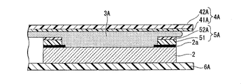
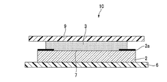
- Drawing 1 is a sectional view showing an example of a transparent surface material with an adhesion layer manufactured using a manufacturing method of a transparent surface material with an adhesion layer of this embodiment, or a manufacturing device of a transparent surface material with an adhesion layer.
- the dimensions, ratios, etc. of the respective components are appropriately changed in order to make the drawings easy to see.
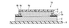
- the transparent surface material 1A with an adhesive layer includes a protective plate 2 (that is, a transparent surface material) in which a frame-shaped light-shielding print portion 2a (that is, a colored layer) is formed on the peripheral edge of one surface, and a light-shielding print portion 2a. It has the adhesion layer 3 which covers the surface of the protective plate 2 of the formed side, and the 1st protection film 4 (1st protection film) which covers the whole surface of the adhesion layer 3.
- a frame-like film 5 that overlaps the frame-shaped light-shielding print portion 2a in a plane is bonded between the light-shielding print portion 2a and the adhesive layer 3.
- 1 A of transparent surface materials with an adhesion layer have the 2nd protective film 6 (2nd protective film) bonded by the whole surface on the opposite side to the side in which the light-shielding printing part 2a was formed in the protective plate 2.
- FIG. is doing.
- 1 A of transparent surface materials with an adhesion layer of this embodiment peel off the 1st protective film 4, and can manufacture a display apparatus by bonding to the display surface of a display panel not shown, as a precursor of a display apparatus. To play a role.
- the display image is visually recognized through the protective plate 2 from the side where the second protective film 6 of the protective plate 2 is bonded.
- the side on which the second protective film 6 of the protective plate 2 is bonded may be referred to as a “visual recognition side”.
- the protection plate 2 is provided on a display surface of a display panel (not shown) and used to protect the display panel, for example.
- the protective plate 2 a glass plate or a transparent resin plate can be used.
- the glass plate is highly transparent to the light emitted from the display panel, and has high light resistance, low birefringence, high planar accuracy, surface scratch resistance (scratch resistance), and high mechanical strength. preferable.
- the glass plate material includes glass materials such as soda lime glass.
- glass materials such as soda lime glass.
- a highly transmissive glass also referred to as white plate glass
- tempered glass may be used as a material of a glass plate, and the glass plate which gave chemical strengthening may be used.
- the material for the transparent resin plate examples include highly transparent resin materials (polycarbonate, polymethyl methacrylate, etc.). If it has the required transparency, a resin plate in which two or more types of resin materials are laminated may be used as the protective plate 2, and a resin composition in which two or more types of resin materials or fillers are mixed is formed. A resin plate as a material may be used.
- the protective plate 2 may be subjected to a surface treatment in order to improve the interfacial adhesive force with the adhesive layer 3.
- a surface treatment method include a method of treating the surface of the protective plate 2 with a silane coupling agent.
- a surface treatment method includes a method of forming a silicon oxide thin film by an oxidation flame using a frame burner.
- the thickness of the protective plate 2 is set in terms of mechanical strength and transparency.
- the protective plate 2 is a glass plate, 0.5 mm to 25 mm is preferable. In applications such as a television receiver and a PC display used indoors, 1 mm to 6 mm is more preferable from the viewpoint of reducing the weight of the display device. For public display applications installed outdoors, 3 mm to 20 mm is more preferable.
- the thickness of the glass plate is preferably about 0.5 mm to 1.5 mm in order to ensure sufficient strength. In the case of a transparent resin plate, 2 mm to 10 mm is preferable.
- the light-shielding printing unit 2a is configured to hide the wiring members and the like connected to the display panel so that only the image display area of the display panel can be seen from the viewing side of the protective plate 2.
- the light-shielding printing portion 2a is preferably formed by ceramic printing using a ceramic paint containing a black pigment or a white pigment because the light-shielding property is high.
- the thickness of the light-shielding print portion 2a is preferably 10 ⁇ m to 20 ⁇ m.
- the thickness of the light-shielding print portion 2a is 30 ⁇ m to 50 ⁇ m. preferable.
- the display panel wiring member or the like has a structure that cannot be seen from the side of the display panel observation, or is concealed by another member such as a housing of the display device, or a bonded object and an adhesive layer other than the display panel
- the light-shielding print portion may not be formed on the protective plate 2 in some cases.
- the translucent part 7 is, for example, substantially the same size as the image display area of the display panel, and is a transparent area so that the image display area of the display panel can be viewed from the viewing side of the protection plate 2.
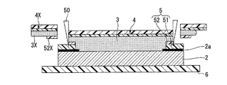
- the frame-shaped film 5 is a film whose purpose is to protect the light-shielding print portion 2a. Specifically, the frame-shaped film 5 cuts the adhesive layer 3 to be described later and the first film 41 or the first film 41 and the second film 42 with a cutting blade during the production of the transparent surface material 1A with the adhesive layer. In doing so, the light-shielding printing unit 2a is protected so that the light-shielding printing unit 2a is not damaged.
- the frame-shaped film 5 includes a region cut by the cutting blade and is bonded to the frame-shaped light-shielding printing unit 2a so as to overlap in a plane.
- the frame-shaped film 5 is formed by laminating a first frame-shaped film 51 provided in contact with the light-shielding printing unit 2 a and a second frame-shaped film 52 provided on the first frame-shaped film 51.
- the 1st frame-shaped film 51 and the 2nd frame-shaped film 52 can be peeled in the interface of both.
- the first frame-like film 51 is formed with the same width as the light-shielding printing part 2a in the surface direction of the protective plate 2 or a narrower width than the light-shielding printing part 2a.
- the frame-shaped film 5 is formed at a position separated from the edge of the opening portion side of the light-shielding printing portion 2a by more than the thickness of the adhesive layer 3, the frame-shaped film 5 is viewed obliquely from the protective plate 2 side. Is preferable because it is difficult to be visually recognized. Further, it is more preferable that the frame-like film 5 is formed at a position separated by twice or more the thickness of the pressure-sensitive adhesive layer 3 because it is more difficult to visually recognize.
- the thickness of the first frame film 51 is 50 ⁇ m to 150 ⁇ m.
- the second frame-shaped film 52 is formed with a narrower width than the first frame-shaped film 51, and the inner periphery is formed at the same position as the inner periphery of the first frame-shaped film 51.
- the width of the second frame film 52 is preferably 1 mm or less.
- the thickness of the second frame-shaped film 52 is 20 ⁇ m to 60 ⁇ m.
- the pressure-sensitive adhesive layer 3 covers the inner side surface and upper surface of the translucent part 7 and the light-shielding printing part 2a on the surface of the protective plate 2, and the inner side surface of the frame-shaped film 5 and the entire upper surface of the second frame-shaped film 52. .
- the interface between the pressure-sensitive adhesive layer 3, the light-shielded printed portion 2a and the frame-shaped film 5 The pressure-sensitive adhesive layer 3 is provided without a gap without generating a void.
- the pressure-sensitive adhesive layer 3 is a layer having a pressure-sensitive adhesive layer of a transparent resin formed by curing a liquid pressure-sensitive adhesive or a pressure-sensitive adhesive precursor material, which will be described later, as a forming material.
- Examples of the material for forming the pressure-sensitive adhesive layer 3 include a curable resin contained in a pressure-sensitive adhesive described later.
- the shear modulus at 25 ° C. preferably 10 3 Pa ⁇ 10 7 Pa, more preferably 10 4 Pa ⁇ 10 6 Pa, particularly preferably 10 4 Pa ⁇ 10 5 Pa.
- the shear modulus of the adhesive layer 3 is 10 3 Pa or more, the shape of the adhesive layer 3 can be maintained. Moreover, even when the thickness of the adhesive layer 3 is relatively thick, the thickness can be kept uniform throughout the adhesive layer 3. Moreover, if the shear elastic modulus is 10 4 Pa or more, it is easy to suppress deformation of the adhesive layer 3 when the first protective film 4 is peeled off. If the shear modulus of the adhesive layer 3 is 10 7 Pa or less, good adhesion can be exhibited at the interface between the adhesive layer 3 and the display panel.
- the resin material forming the adhesive layer 3 has a relatively high molecular mobility. Therefore, after laminating the transparent surface material with an adhesive layer 1A and the display panel in a reduced pressure atmosphere, when the bonded body is returned to the atmospheric pressure atmosphere, there is a gap at the interface between the transparent surface material and the display panel. Even if it occurs, the volume of the void tends to decrease due to the differential pressure between the pressure in the void (pressure in a state where pressure is reduced) and the pressure applied to the adhesive layer 3 (that is, atmospheric pressure). In addition, the gas in the void whose volume has been reduced dissolves in the adhesive layer 3 and is easily absorbed. Moreover, if the shear elastic modulus is 10 5 Pa or less, the gap at the interface between the pressure-sensitive adhesive layer 3 and the display panel can be eliminated in a shorter time.
- the shape can be sufficiently maintained even when the shear elastic modulus is sufficiently small, for example, even when the shear elastic modulus is 10 3 Pa to 10 7 Pa.
- the shear elastic modulus at 25 ° C. of the pressure-sensitive adhesive layer 3 is measured as follows. Using a rheometer (Modular rheometer Physica MCR-301, manufactured by Anton cit), the gap between the measuring spindle and the translucent plate was the same as the average thickness of the adhesive layer 3, and the uncured gap was Place the adhesive. Furthermore, the shear elastic modulus of the curing process is measured while applying heat and light necessary for curing to the uncured adhesive, and the measured value under a predetermined curing condition is defined as the shear elastic modulus of the adhesive layer 3.
- the average thickness of the pressure-sensitive adhesive layer 3 overlapping the light transmitting portion 7 is preferably 0.03 mm to 2 mm, and more preferably 0.1 mm to 0.8 mm. If the average thickness of the pressure-sensitive adhesive layer 3 is 0.03 mm or more, the pressure-sensitive adhesive layer 3 can effectively buffer an impact caused by an external force from the protective plate 2 side, thereby protecting the display panel. Moreover, even when a foreign substance not exceeding the thickness of the adhesive layer 3 is mixed between the transparent surface material 1A with the adhesive layer and the display panel at the time of manufacturing the display device, the average thickness of the adhesive layer 3 greatly changes. No effect on transparency performance. If the average thickness of the pressure-sensitive adhesive layer 3 is 2 mm or less, it is difficult for voids to remain in the pressure-sensitive adhesive layer 3, and the entire thickness of the display device does not become unnecessarily thick.
- Examples of a method for adjusting the thickness of the pressure-sensitive adhesive layer 3 include a method for adjusting the amount of the pressure-sensitive adhesive supplied to the surface of the first protective film 4 in the manufacturing method described later.
- the 1st protective film 4 protects the surface of the adhesion layer 3, and maintains the shape of the adhesion layer 3 until just before bonding 1A of transparent surface materials with an adhesion layer, and a display panel.
- the first protective film 4 is surrounded by a frame-like remaining portion 4b and a remaining portion 4b at a peripheral edge by a cut 4c formed in a portion overlapping the light-shielding printed portion 2a when viewed from the normal direction of the protective plate 2. It can be separated from or separated from the inner peeling portion 4a.
- the peeling part 4a is peeled from the pressure-sensitive adhesive layer 3 when the transparent surface material with adhesive layer 1A and the display panel are bonded together. Thereby, the adhesion layer 3 covered with the peeling part 4a is exposed. 1 A of transparent surface materials with an adhesion layer are bonded by a display panel by making the adhesion layer 3 of the part with the peeling part 4a contact a display panel. Therefore, the size of the peeling portion 4a is substantially the same as the surface where the display panel is bonded to the adhesive layer 3 when the transparent surface material with adhesive layer 1A is bonded to the display panel, and the image display area of the display panel It is preferable that it is almost the same as or larger than one.
- the remaining portion 4b continues to protect the surface of the peripheral portion of the adhesive layer 3 in the display device even after the transparent surface material with adhesive layer 1A and the display panel are bonded together. Moreover, the remaining part 4b suppresses the drop-off of fragments from the peripheral part of the protective plate 2 adhered via the adhesive layer 3 when the protective plate 2 is cracked. Without providing the remaining portion 4b, the entire first protective film 4 can be peeled off and bonded to the display panel. When the display panel is housed in a metal frame or the like and the display area is viewed through the opening of the frame, the adhesive layer 3 and the display panel are bonded to each other through the opening of the frame. At this time, the opening of the frame and the size of the display area may be close to each other. In this case, it is preferable not to provide the remaining portion 4b.
- the first protective film 4 is formed by laminating a first film 41 disposed on the adhesive layer 3 side and a second film 42 disposed on the opposite side of the adhesive layer 3.
- the first film 41 has a low adhesion to the adhesive layer 3 and is configured to easily peel the entire first protective film 4 from the adhesive layer 3.
- the first film 41 is preferably made of polyethylene, polypropylene, or fluorine resin.
- a polyolefin-based resin polyethylene, polypropylene, or the like
- the ten-point average roughness Rz of the surface in contact with the adhesive layer 3 in the first film 41 is preferably 2.0 ⁇ m to 20 ⁇ m in order to suppress the remaining of voids when bonded to the display panel.
- the thickness of the first film 41 varies depending on the material, but when a relatively flexible film such as polyethylene or polypropylene is used, it is preferably 10 ⁇ m to 100 ⁇ m. If the thickness of the 1st film 41 is 10 micrometers or more, when peeling the 1st protective film 4 from the adhesion layer 3, the excessive deformation
- the second film 42 a film that is less likely to stretch than the first film 41 with respect to tensile stress is used.
- the second film 42 has a function of suppressing the elongation of the first protective film 4 when a tensile stress is applied to the entire first protective film 4. Therefore, the second film 42 is preferably made of a resin material having a smaller elongation than that of the first film 41.
- the material for forming the second film 42 include polyester resins such as polyethylene terephthalate and polyethylene naphthalate, and polyamide resins such as nylon-6 and nylon-66.
- the thickness of the second film 42 is preferably 5 ⁇ m to 50 ⁇ m when a film made of a polyester resin such as PET is used. If the thickness of the 2nd film 42 is 5 micrometers or more, when peeling the 1st protective film 4 from the adhesion layer 3, the excessive deformation
- the total thickness of the first protective film 4 varies depending on the resin used, a film having a polyolefin-based resin as a forming material is used as the first film 41, and a film having a polyester-based resin as a forming material is used as the second film 42.
- it is preferably 40 ⁇ m to 100 ⁇ m. If the thickness of the 1st protective film 4 is 40 micrometers or more, when peeling the 1st protective film 4 from the adhesion layer 3, a deformation
- the first protective film Only the first film may be used as the first protective film.
- a gas barrier layer is provided on the surface of the first film in contact with the first film or on either surface of the second film, it is preferable because a gap at the time of bonding with the display panel can be suppressed.
- an inorganic compound or a material in which an inorganic compound is dispersed in a resin can be used.
- a transparent conductive layer can be provided on the back surface of the surface of the first protective film that contacts the adhesive layer.
- the first protective film having such a configuration is preferable because when the IPS liquid crystal display panel and the transparent surface material with the adhesive layer 1A are bonded, the liquid crystal panel can be easily grounded.
- the surface resistance of the transparent conductive layer is preferably 10 2 to 10 8 ⁇ / ⁇ .
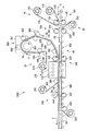
- FIG. 2 is a schematic diagram illustrating an example of an apparatus for producing a transparent surface material with an adhesive layer of the present embodiment.
- the manufacturing apparatus 1000 continuously laminates the frame-shaped film 5, the adhesive layer 3, and the first protective film 4 while conveying the plurality of protective plates 2, and the above-described transparent surface material with the adhesive layer is laminated. It is a device to manufacture.
- the manufacturing apparatus 1000 includes a first bonding unit 10 that bonds the frame-shaped film 5 to the light-shielding printing unit 2 a of the protection plate 2 and a second bonding that bonds the second protective film 6 to the protection plate 2. It has the bonding part 20, the 3rd bonding part 30 which bonds the 1st protective film 4 via the adhesion layer 3 with respect to the protection board 2, and the conveyance part 40 which conveys the some protection board 2. is doing. Furthermore, the manufacturing apparatus 1000 has a cutout part (not shown) for cutting out the first protective film 4 for each protective plate 2.
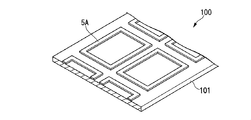
- FIG. 3A to 3C are explanatory views of members used in the manufacturing apparatus 1000.
- FIG. FIG. 3A is an explanatory diagram of the first bonding film 100, and the first bonding film 100 is a member used in the first bonding unit 10.
- a plurality of frame films 5 ⁇ / b> A are arranged on the surface of the first base film 101.
- FIG. 3A is a view of the first bonding film 100 as viewed from the frame-shaped film 5A side. A part of the frame-shaped film 5 ⁇ / b> A is cut off by processing described later to become the above-described frame-shaped film 5.
- the first bonding film 100 for example, two frame films 5 ⁇ / b> A are arranged in the width direction of the first base film 101, and a plurality of frame films 5 ⁇ / b> A are provided in the longitudinal direction of the first base film 101.
- FIG. 3B is an explanatory diagram of the second bonding film 200.
- the second bonding film 200 is a member used in the second bonding unit 20.
- the second protective film original fabric 6A is bonded to the second base film 201.
- the 2nd protective film original fabric 6A is exhibiting strip
- FIG. 3C is an explanatory diagram of the third bonding film 300.
- the third bonding film 300 is a member used in the third bonding unit 30.
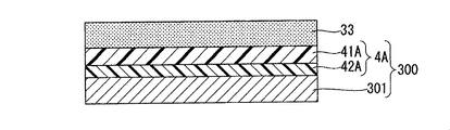
- 4 A of 1st protective film original fabrics (protective film original fabric) are bonded to the 3rd base film 301.
- the first protective film original fabric 4A has a strip shape. 4 A of 1st protective film original fabrics become the above-mentioned 1st protective film 4 by cut
- the first protective film original 4A includes a second film original 42A corresponding to the second film 42 in FIG. 1 and a first film original 41A corresponding to the first film 41 on the third base film 301 side. It is laminated from.
- the protection plate 2 on which the light-shielding printing unit 2 a is formed is first conveyed to the first bonding unit 10.
- the 1st bonding part 10 bonds the frame-shaped film 5A with respect to the light-shielding printing part 2a which the protective plate 2 has using the 1st bonding film 100.
- the 1st bonding part 10 has the 1st bonding film 100, the 1st unwinding roll 110, the 1st winding roll 120, and the 1st bonding roll 130. As shown in FIG.
- the 1st unwinding roll 110 unwinds the 1st bonding film 100 wound up in roll shape one by one.
- the first winding roll 120 winds up the first base film 101 after the frame film 5 ⁇ / b> A is bonded to the protective plate 2.
- the first bonding roll 130 bonds the protective plate 2 and the frame-shaped film 5A.
- the 1st bonding roll 130 has a pair of roll 131 and the roll 132.
- FIG. The 1st bonding roll 130 is bonding the frame-shaped film 5A to the protection board 2 by pinching and pressing the protection board 2 and the 1st bonding film 100 between a pair of rolls.
- the protective plate 2 is conveyed to the second bonding unit 20.
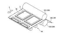
- the second bonding unit 20 bonds the second protective film original fabric 6 ⁇ / b> A to the protective plate 2 using the second bonding film 200.
- 6A of 2nd protective film original fabrics are bonded continuously with respect to the some protective board 2. As shown in FIG.
- the 2nd bonding part 20 is the 2nd bonding film 200, the 2nd unwinding roll 210, the 2nd winding roll 220, the 2nd bonding roll 230, the cutting part 240, the peeling roll 250, have.
- the 2nd unwinding roll 210 unwinds the 2nd bonding film 200 wound up in roll shape one by one.
- the 2nd winding roll 220 winds up the 2nd base film 201 after bonding 6 A of 2nd protective film original fabrics to the protective board 2.
- the second bonding roll 230 bonds the protective plate 2 and the second protective film original fabric 6A.
- the cutting part 240 bonds the second protective film original fabric 6A and the first protective film original fabric 4A to the protective plate 2, and then attaches the second protective film original fabric 6A and the first protective film original fabric 4A to the respective original fabrics. Cut in a direction crossing the longitudinal direction.
- the peeling roll 250 peels the second base film 201 from the protective plate 2.
- the 2nd bonding roll 230 has a pair of rolls 231 and rolls 232.
- the 2nd bonding roll 230 is bonding the 2nd protective film original fabric 6A to the protection board 2 by pinching and pressing the protection board 2 and the 2nd bonding film 200 between a pair of rolls. .
- the protection board 2 is conveyed by the 3rd bonding part 30.
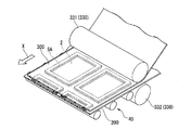
- FIG. The 3rd bonding part 30 bonds 4A of 1st protective film original fabrics to the protective board 2, conveying the 3rd bonding film 300 to the arrow direction shown with the code
- the first protective film original fabric 4A is bonded to the protective plate 2 while an adhesive is applied to the surface.
- 4A of 1st protective film raw fabrics are continuously bonded with respect to the some protective board 2. As shown in FIG.
- the 3rd bonding part 30 is the 3rd bonding film 300, the 3rd unwinding roll 310, the 3rd winding roll 320, the 3rd bonding roll 330, the 1st application part 340, and 1st hardening.
- a part 350 (first curing part), a second application part 360, a second curing part 370 (second curing part), and a peeling roll 380 are provided.
- the 3rd unwinding roll 310 unwinds the 3rd bonding film 300 wound up in roll shape one by one.
- the 3rd winding roll 320 winds up the 3rd base film 301 after bonding 4 A of 1st protective film original fabrics to the protective board 2.
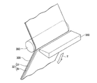
- FIG. The third bonding roll 330 bonds the protective plate 2 and the first protective film raw fabric 4A.
- the 1st application part 340, the 1st hardening part 350, and the 2nd application part 360 are the conveyance processes of the 3rd bonding film 300, and are the 3rd unwinding roll 310 and the 3rd bonding roll 330. It is provided in between.
- the first curing unit 350 cures the adhesive applied by the first application unit 340.
- rolls 391, 392, 393, 394, and 395 are provided between the third unwinding roll 310 and the third bonding roll 330.
- Rolls 391, 392, 393, 394, 395 convey the third bonding film 300.
- the roll 392 also has a function as a backup roll when applying the adhesive in the first application unit 340.
- the roll 393 also has a function as a backup roll when the adhesive is applied in the second application unit 360.
- the 2nd hardening part 370 and the peeling roll 380 are provided between the 3rd bonding roll 330 and the 3rd winding roll 320 in the conveyance process of the 3rd bonding film 300.
- FIG. The second curing unit 370 cures the adhesive applied by the first application unit 340 and the second application unit 360.
- the peeling roll 380 peels the third base film 301 from the protective plate 2.
- the 3rd bonding roll 330 has a pair of roll 331 and roll 332.
- the 3rd bonding roll 330 is bonding the 1st protective film raw fabric 4A to the protection board 2 by pinching and pressing the protection board 2 and the 3rd bonding film 300 between a pair of rolls. .
- the first application unit 340 and the second application unit 360 apply, for example, a liquid composition containing a curable compound as an adhesive or a precursor material of the adhesive.
- the viscosity of the adhesive or the precursor material of the adhesive is preferably 1 Pa ⁇ s to 100 Pa ⁇ s, more preferably 2 Pa ⁇ s to 50 Pa ⁇ s, and further preferably 3 Pa ⁇ s to 30 Pa ⁇ s.
- the viscosity of the pressure-sensitive adhesive or pressure-sensitive adhesive precursor material is 1 Pa ⁇ s or more, the coating layer does not spread too much at the time of application, and the height of the pressure-sensitive adhesive or pressure-sensitive adhesive precursor material layer can be sufficiently maintained.
- the viscosity of the pressure-sensitive adhesive or pressure-sensitive adhesive precursor material is 100 Pa ⁇ s or less, the pressure-sensitive adhesive or pressure-sensitive adhesive precursor material can be easily applied.
- the viscosity of the pressure-sensitive adhesive or pressure-sensitive adhesive precursor material is measured at 25 ° C. using an E-type viscometer.
- the pressure-sensitive adhesive may be a photocurable resin composition or a thermosetting resin composition.
- a photocurable resin composition containing a curable compound and a polymerization initiator is preferable because it can be cured at a low temperature and has a high curing rate.
- an example using a photocurable resin composition will be described.
- the curable compound contained in the pressure-sensitive adhesive 1 of the oligomer (A) having a curable group and having a number average molecular weight of 1,000 to 100,000 from the viewpoint of easily adjusting the viscosity to the above range.
- the total (100% by mass) is preferably 20% by mass to 80% by mass.
- Examples of the curable group of the oligomer (A) include addition polymerizable unsaturated groups (acryloyloxy group, methacryloyloxy group, etc.) or combinations of unsaturated groups and thiol groups.
- a group selected from an acryloyloxy group and a methacryloyloxy group is preferable as the curable group of the oligomer (A) from the viewpoint of a high curing speed and a highly transparent adhesive layer.
- the oligomer (A) preferably has an average of 1.8 to 4 curable groups per molecule from the viewpoint of the curability of the pressure-sensitive adhesive and the mechanical properties of the pressure-sensitive adhesive layer.
- the oligomer (A) include urethane oligomers having a urethane bond, poly (meth) acrylates of polyoxyalkylene polyols, poly (meth) acrylates of polyester polyols, and the like.
- the urethane oligomer (A1) is preferable because the mechanical properties of the cured resin, the adhesiveness with the transparent surface material or the display panel can be widely adjusted by the molecular design of the urethane chain.
- An oligomer (A) may be used individually by 1 type, and may use 2 or more types together.
- Examples of the curable group of the monomer (B) include addition polymerizable unsaturated groups such as an acryloyloxy group and a methacryloyloxy group, or a combination of an unsaturated group and a thiol group.
- a group selected from an acryloyloxy group and a methacryloyloxy group is preferable as the curable group of the monomer (B) from the viewpoint of a high curing rate and a highly transparent adhesive layer.
- the monomer (B) preferably contains a monomer (B3) having a hydroxyl group from the viewpoint of adhesion between the transparent surface material or the display panel and the adhesive layer and solubility of various additives described later.
- Examples of the monomer (B3) having a hydroxyl group include a hydroxy acrylate having a hydroxyalkyl group having 1 to 2 hydroxyl groups and 3 to 8 carbon atoms, or hydroxy methacrylate (2-hydroxypropyl acrylate, 2-hydroxybutyl acrylate, 4- Hydroxybutyl acrylate, 6-hydroxyhexyl acrylate, 2-hydroxypropyl methacrylate, 2-hydroxybutyl methacrylate, 4-hydroxybutyl methacrylate, 6-hydroxyhexyl methacrylate, etc.), preferably 4-hydroxybutyl acrylate or 2-hydroxybutyl Methacrylate is particularly preferred.
- a monomer (B) may also be used individually by 1 type, and may use 2 or more types together.
- the monomer (B ′) may contain the following monomer (B4). After the monomer (B4) is bonded to the display panel and the transparent surface material with the adhesive layer in a reduced pressure atmosphere, the void generated in the adhesive layer when the pressure is returned to the atmospheric pressure atmosphere is lost. It may contribute to shortening of time. However, when the monomer (B4) is contained, the time required for curing the pressure-sensitive adhesive tends to be long.
- the monomer (B4) is selected from alkyl acrylate having an alkyl group having 8 to 22 carbon atoms or alkyl methacrylate, and n-decyl acrylate, n-dodecyl acrylate, n-octadecyl acrylate, n-dodecyl methacrylate, n-octadecyl Examples thereof include methacrylate and n-behenyl methacrylate.
- n-decyl acrylate, n-dodecyl acrylate, n-dodecyl methacrylate, and n-octadecyl methacrylate are preferable.
- the pressure-sensitive adhesive may contain the following non-curable oligomer (D).
- the non-curable oligomer (D) does not undergo a curing reaction with the oligomer (A) and the monomer (B) when the pressure-sensitive adhesive is cured.
- the number average molecular weight (Mn) is 400 to 8,000 and the number of hydroxyl groups per molecule is 0.00. It is an oligomer having 8 to 3 hydroxyl groups. Effect of stabilizing the non-curable oligomer (D) in the cured adhesive layer by the interaction between the hydroxyl group derived from the cured product containing the monomer (B3) and the hydroxyl group of the non-curable oligomer (D) Is easy to obtain. It is presumed that hydrogen bonds are involved in the interaction between the monomer (B3) and the non-curable oligomer (D).
- a non-curable oligomer (D) may be used individually by 1 type, and may use 2 or more types together.
- non-curable oligomer (D) containing a hydroxyl group examples include a high molecular weight polyol.
- the non-curable oligomer (D) polyoxyalkylene polyol, polyester polyol, and polycarbonate polyol are preferable.
- the non-curable oligomer (D) contains a polyol used for the synthesis of the oligomer (A), the compatibility of the adhesive material before curing is preferably improved.
- polymerization initiator examples include photopolymerization initiators such as acetophenone, ketal, benzoin or benzoin ether, phosphine oxide, benzophenone, thioxanthone, and quinone.
- photopolymerization initiators such as acetophenone, ketal, benzoin or benzoin ether, phosphine oxide, benzophenone, thioxanthone, and quinone.
- first application unit 340 and the second application unit 360 a generally known device for applying a liquid adhesive can be used.
- a dispenser a die coater, a bar coater, a slit coater, a spray application device, or a printing machine can be used, for example.
- the first curing unit 350 (light irradiation device in the present embodiment) includes a chamber 351, a plurality of (two in the drawing) light sources 352 disposed in the chamber 351, and the third bonding film 300 in the chamber 351. And a backup roll 353 that hangs around.
- the inside of the chamber 351 is an inert gas atmosphere.
- the chamber 351 is filled with nitrogen, and the oxygen concentration is controlled to 100 ppm or less. Since the inside of the chamber 351 is in an inert gas atmosphere, when the above-mentioned adhesive is irradiated with ultraviolet rays (light irradiation) to cause a curing reaction, radicals generated in the resin material constituting the adhesive by ultraviolet irradiation are oxygen It is possible to suppress the side reaction that is deactivated by.
- the light source 352 is a light source that can irradiate ultraviolet rays.
- a commonly known high-pressure mercury lamp or metal halide lamp can be used.
- the second curing unit 370 (light irradiation device) includes a chamber 371 and a plurality (four in the drawing) of light sources 372 arranged in the chamber 371.
- the light source 372 is a light source that can irradiate ultraviolet rays.
- a light source 372 for example, a generally known high-pressure mercury lamp or metal halide lamp can be used.
- a chemical lamp capable of irradiating visible light in addition to ultraviolet light or an electrodeless ultraviolet irradiation lamp can be suitably used.
- the cutting unit 240 has a rotary blade 241 and a support roll 242.
- the rotary blade 241 cuts the second protective film original fabric 6A and the first protective film original fabric 4A from the first protective film original fabric 4A side.
- the support roll 242 supports from the second protective film original fabric 6 ⁇ / b> A side when cutting with the rotary blade 241.
- the cutting unit 240 uses the support roll 242 to support the second protective film original fabric 6A and the first protective film original fabric 4A while using the rotary blade 241 in the direction intersecting the longitudinal direction of each original fabric.
- the protective film original fabric 6A and the first protective film original fabric 4A are cut.
- the conveyance unit 40 is a roll conveyor in which a plurality of rolls 400 are arranged, and is formed across each bonding unit.
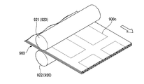
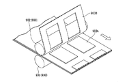
- the frame-shaped film 5A is first bonded by the 1st bonding part 10 with respect to the some protective board 2 conveyed by the conveyance part 40.
- the second protective film raw fabric 6 ⁇ / b> A is bonded to the plurality of protective plates 2 at the second bonding unit 20.
- the first protective film raw fabric 4 ⁇ / b> A is bonded to the plurality of protective plates 2 at the third bonding unit 30.
- the transparent surface material 1A with the adhesion layer made into the objective is manufactured by carving for every 1st protective film 4 (every protective plate 2) by the cutting part 240 which the 2nd bonding part 20 has, and the not-shown cutting part. .
- the transparent surface material with adhesive layer 1A can be efficiently manufactured.
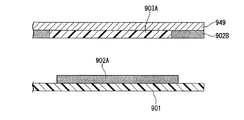
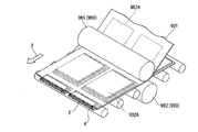
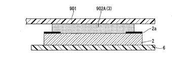
- FIG. 4A to FIG. 14B are explanatory views showing a method for manufacturing a transparent surface material with an adhesive layer of the present embodiment.
- Each figure has shown about the method of manufacturing 1 A of transparent surface materials with an adhesion layer using the manufacturing apparatus 1000 mentioned above.
- a of each figure is a schematic perspective view which shows a part of manufacturing apparatus 1000
- B of each figure is a schematic sectional drawing of the member which comprises the transparent surface material with an adhesion layer in each process.
- the manufacturing method of the transparent surface material with the adhesion layer can be implemented without using the above-described manufacturing apparatus.
- FIGS. 2 and 4A to 14B will be given with reference to FIGS. 2 and 4A to 14B.
- the plurality of protection plates 2 are horizontally transported in the transport direction indicated by the symbol X in the drawing using the transport unit 40.
- a state is shown in which two protective plates 2 are arranged and conveyed in a direction (width direction) perpendicular to the conveyance direction.
- the sheets may be transported one by one, or three or more sheets may be transported side by side in the width direction.
- “while transporting a plurality of transparent surface materials” means a mode in which two or more protective plates 2 are arranged and transported in a direction (width direction) perpendicular to the transport direction, and a protective plate 2 in the transport direction. This includes both forms in which two or more sheets are conveyed side by side.
- the protective plate 2 is provided with a light-shielding printing portion 2a at the peripheral edge of the upper surface.
- the frame-shaped film 5 ⁇ / b> A is bonded onto the light-shielding printing portion 2 a of the protective plate 2 (a transparent surface material with a frame-shaped film is formed).
- the protective plate 2 and the frame-shaped film 5A are provided with an adhesive layer (not shown) on either the surface of the frame-shaped film 5A facing the protective plate 2 or the upper surface of the light-shielding printing portion 2a of the protective plate 2. It is good to paste through this adhesion layer.
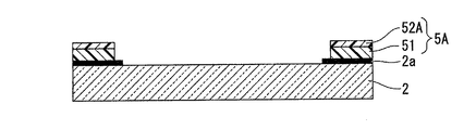
- the frame-shaped film 5A is formed by laminating a first frame-shaped film 51 and a second frame-shaped film 52A from the light-shielding printing portion 2a side.
- the frame-shaped film 5A overlaps with the light-shielding printing portion 2a in a planar manner.
- the frame-shaped film 5A is provided in order to suppress damage to the light-shielding print portion 2a during processing in FIGS. 13A and 13B described later. Therefore, the frame-shaped film 5A may have a width narrower than that of the light-shielding printing portion 2a as long as it is provided at a position that overlaps with a cutting position by a cutting blade (described later) used during processing.
- the second protective film original fabric 6 ⁇ / b> A is provided on the surface opposite to the surface on which the light shielding printing portion 2 a of the protective plate 2 is provided.
- the 2nd bonding film 200 is bonded by making oppose.
- FIGS. 7A and 7B in the first application part 340 of FIG. 2, a liquid adhesive is continuously applied to the surface of the first film original 41 ⁇ / b> A of the third bonding film 300 in a strip shape.
- the pressure-sensitive adhesive layer 3a is formed (step of applying a pressure-sensitive adhesive).
- FIG. 7B shows a cross-sectional view of the third bonding film 300 after application of the pressure-sensitive adhesive layer 3a.
- the adhesive layer 3a is irradiated with light (ultraviolet rays) to partially cure the adhesive layer 3a. (Step of forming a protective film original fabric with a semi-cured layer).
- a part of the pressure-sensitive adhesive layer 3a has been cured means that when the polymerization degree of the pressure-sensitive adhesive layer 3 included in the transparent surface material with adhesive layer 1A shown in FIG. This means that the curing process is finished without polymerization.
- “a part of the pressure-sensitive adhesive layer 3 a has been cured” means that the pressure-sensitive adhesive layer 3 a is polymerized (cured), but the polymerization is performed up to the degree of polymerization of the pressure-sensitive adhesive layer 3 included in the transparent surface material 1 A with the pressure-sensitive adhesive layer. This means that (curing) has not progressed.
- the polymerization until reaching the polymerization degree (target polymerization degree) of the adhesive layer 3 is assumed to be “full curing”, it can be said that the intermediate stage of the polymerization is in a “half-cured” state.
- the semi-cured layer 31 is a layer “a part of the pressure-sensitive adhesive layer 3 a has been cured”, and indicates that the polymerization has not progressed until the degree of polymerization of the pressure-sensitive adhesive layer 3.
- the difference in the degree of polymerization of the semi-cured layer 31 can be confirmed by determining the shear elastic modulus at 25 ° C. of the semi-cured layer 31.
- the shear elastic modulus was measured using a rheometer (manufactured by Anton titanium, modular rheometer Physica MCR-301), and the sampled semi-cured layer 31 had a gap of 0.4 mm between the measuring spindle and the translucent plate. And by measuring the shear modulus at a measurement frequency of 1 Hz.
- the shear elastic modulus of the semi-cured layer 31 is preferably 10 Pa or more and 10,000 Pa or less, and more preferably 50 Pa or more and 5,000 Pa or less.
- a liquid adhesive is continuously applied again in a strip shape on the surface of the semi-cured layer 31 to form the adhesive layer 3 b.
- the semi-cured layer 31 which is a layer closer to the first protective film original fabric 4A is more suitable for the first protective film original fabric. Curing proceeds more than the pressure-sensitive adhesive layer 3b which is a layer far from 4A (surface side), and the surface side is a layer having higher fluidity.
- the adhesive applied by the second application unit 360 may be the same as or different from the adhesive applied by the first application unit 340.
- the layer formed by laminating the semi-cured layer 31 and the pressure-sensitive adhesive layer 3b is a layer in which the polymerization has not progressed until the degree of polymerization of the pressure-sensitive adhesive layer 3, in the following description, the semi-cured layer 31 and the pressure-sensitive adhesive The layer formed by laminating the layer 3b is referred to as a semi-cured layer 32.
- the pressure-sensitive adhesive layer 3b in the semi-cured layer 32 facing the protective plate 2, is not hardened more than the semi-cured layer 31, and is a layer having relatively high fluidity. Therefore, as shown in FIG. 10B, while the pressure-sensitive adhesive layer 3b is plastically deformed, it is possible to easily form a layer in close contact with the inner surface of the light-shielding print portion 2a or the frame-shaped film 5A or the upper surface of the protective plate 2 without any gaps. Formation of voids can be suppressed.
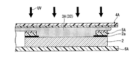
- the semi-cured layer 32 is irradiated with ultraviolet UV through the third bonding film 300 to form the adhesive layer 3A (adhesive layer).
- the adhesive layer 3A adheresive layer
- Step to make a layer The pressure-sensitive adhesive layer 3A is formed across the plurality of protective plates 2, and is cut by processing described later to form the above-described pressure-sensitive adhesive layer 3.
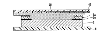
- the first protective film original fabric 4A and the second protective film original fabric 6A are cut in the width direction by the cutting portion 240 of FIG. Then, the 2nd base film 201 of the 2nd bonding film 200 is peeled with the peeling roll 250 of FIG. 2, Furthermore, 4 A of 1st protective film original fabrics and 6 A of 2nd protective film original fabrics were used using the cutting device not shown. Is cut for each protective plate 2. In the figure, it is shown that the adhesive layer 3B and the first protective film 4B are obtained by cutting the adhesive layer 3A and the first protective film original fabric 4A for each protective plate 2.
- the frame-shaped cutting blade 50 is moved downward, beyond the interface between the second frame-shaped film 52 ⁇ / b> A and the first frame-shaped film 51, the first frame-shaped The frame-shaped film 5A is cut until reaching the film 51, and the first protective film 4 and the frame-shaped film 5 are formed (step of cutting).
- the excess portion 52X of the second frame-shaped film 52A, the excess portion 3X of the adhesive layer 3A attached to the frame-shaped film 5A, and the excess portion 4X of the first protective film 4B are removed.
- a cut which is a cut mark is formed on the surface of the first frame-shaped film 51.
- the cutting blade 50 corresponds to the cut-out portion described above.
- the cutting edge of the cutting blade 50 is displaced by a predetermined position in the vertical direction due to, for example, the position control accuracy of the moving device when moving the cutting blade 50 downward or the undulation of the surface of the protective plate 2. It has a width (for example, 20 ⁇ m to 30 ⁇ m). Even in such a case, for example, the thickness of the first frame-shaped film 51 is set to 50 ⁇ m to 150 ⁇ m, the thickness of the second frame-shaped film 52A is set to 20 ⁇ m to 60 ⁇ m, and the cutting edge of the cutting blade 50 when moving downward is used.
- the 2nd frame-shaped film 52A can be cut
- the excess portions 3X, 4X, and 52X can be easily removed.
- a cut 4c is formed using a knife 60 in the portion of the first protective film 4 that overlaps the light-shielding print portion 2a in a plan view, and the first protective film 4 is formed at the peripheral portion.
- the remaining portion 4b is divided into an inner peeling portion 4a surrounded by the remaining portion 4b.
- a cut 4c is formed so as to connect the diagonal lines of the peeling portion 4a, and the peeling portion 4a is divided into a plurality (four in the figure).
- the peeling portion 4a divided into four is peeled from the position where the cut 4c intersects at the center of the peeling portion 4a in the plan view toward the arrow direction (the direction of the remaining portion 4b).
- the stress at the time of peeling hardly concentrates on the remaining part 4b, and interface peeling between the first film 41 and the second film 42 in the remaining part 4b can be suppressed.
- 1 A of transparent surface materials with an adhesion layer of this embodiment are manufactured.
- the transparent surface material with an adhesive layer can be produced with high productivity.
- FIG. 15A and FIG. 15B are schematic views showing a modification of the manufacturing apparatus of the transparent surface material with the adhesive layer of the present embodiment.
- a in the figure is a schematic perspective view showing a part of the manufacturing apparatus 1000
- B in the figure is a schematic sectional view of members constituting the transparent surface material with an adhesive layer in the same step.
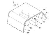
- the figure is a figure which shows the modification about the 1st hardening part 350 in FIG. 2, and is a figure corresponding to FIG. 8A and FIG. 8B.
- the 3rd bonding film 300 in which the adhesive layer 3a was formed is passed over the rolls 355,356 in the chamber not shown. .
- ultraviolet-ray UV is irradiated to the adhesive layer 3a through the 3rd bonding film 300, and the semi-hardened layer 33 is formed.
- the adhesive layer 3 a is first positioned close to the third bonding film 300.
- the polymerization initiator present in the layer absorbs ultraviolet UV, and the polymerization initiator present on the surface side of the pressure-sensitive adhesive layer 3a absorbs attenuated ultraviolet UV. Therefore, in the adhesive layer 3a, at a position close to the third bonding film 300, more polymerization initiators react than the surface side of the adhesive layer 3a, and the adhesive constituting the adhesive layer 3a is polymerized. It will be.
- the 3rd bonding film 300 side (1st protective film original fabric 4A side) of the semi-hardened layer 33 is the surface of the semi-hardened layer 33.
- Curing proceeds more than the side, and the degree of polymerization in the thickness direction of the layer is inclined, so that the surface side can be a layer having higher fluidity.
- the surface side of the semi-cured layer 33 is in close contact with the inner surface of the light-shielding print portion 2a and the frame-like film 5A and the upper surface of the protective plate 2 without a gap while plastically deforming. Can be easily formed, and the formation of voids can be suppressed.
- the second application unit 360 is provided on the downstream side of the first curing unit 350, but the second application unit 360 is provided between the first application unit 340 and the first curing unit 350. Also good.
- coated by the 1st application part 340 is apply
- the first protective film raw fabric 4A side of the obtained semi-cured layer may be cured more than the surface side of the semi-cured layer by ultraviolet irradiation in the first cured part 350. it can.
- the second application unit 360 is provided, but the second application unit 360 may not be provided.
- the semi-cured layer 31 formed by the first cured part 350 has no fluidity because the polymerization has not progressed to the final degree of polymerization as a product even though the degree of polymerization is not inclined. In comparison with the case where the polymerization progresses to the final degree of polymerization, it is more likely to be plastically deformed. Therefore, formation of a space
- the photocurable resin is used as the adhesive, but the present invention is not limited to this, and a thermosetting resin may be used.
- a heating device may be used as the first curing unit 350 and the second curing unit 370, and the time for heating in each curing unit may be appropriately adjusted according to the curing rate.
- the ultraviolet irradiation was performed in the 1st hardening part 350 and the 2nd hardening part 370, even if any one is a heating apparatus, the transparent surface material with an adhesion layer can be manufactured.
- the first application unit 340 and the second application unit 360 apply the adhesive in a strip shape, but the adhesive may be selectively applied only to a position facing the protective plate 2. Absent.
- the 3rd bonding film 300 had the 3rd base film 301 and showed the structure wound up by the 3rd winding roll 320 after use, the 3rd base film 301 is not used. It can also be configured. For example, if it can be operated as a state in which the third bonding film 300 is stretched without bending by the force when sandwiched by the third bonding roll 330 and sent to the downstream side, the first protection is provided in the third bonding portion 30. Only the original film 4A may be used.
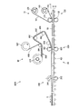
- FIGS. 16 and 17 are schematic views illustrating an example of a manufacturing apparatus for a transparent surface material with an adhesive layer of the present embodiment.
- the manufacturing apparatus 2000 continuously laminates the frame-shaped film 5, the adhesive layer 3, and the first protective film 4 while transporting the plurality of protective plates 2, and the above-described transparent surface material with the adhesive layer is laminated. It is a device to manufacture.
- the manufacturing apparatus 2000 includes a first bonding unit (first bonding unit) 10 that bonds the frame-shaped film 5 to the light-shielding printing unit 2 a of the protective plate 2, and second protection for the protective plate 2.
- the 2nd bonding part 20 which bonds the film 6 and the 3rd bonding part (2nd bonding part) 70 which bonds the 1st protective film 4 via the adhesion layer 3 with respect to the protective board 2 and
- a transport unit 40 that transports the plurality of protection plates 2.
- the manufacturing apparatus 2000 has a cutout part (not shown) for cutting out the first protective film 4 for each protective plate 2.
- FIG. 18 is an explanatory diagram of members used in the manufacturing apparatus 2000.
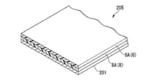
- FIG. 18 is an explanatory diagram of the second bonding film 205.
- the second bonding film 205 is a member used in the second bonding unit 20.
- the support film original fabric 8A and the second protective film original fabric 6A are laminated on the second base film 201 from the second base film 201 side.
- the support film original fabric 8A is a film (support film 8 to be described later) used as a support for handling a plurality of transparent surface materials together during the production of the transparent surface material with an adhesive layer.
- a PET film having a thickness of 100 ⁇ m can be used as the support film original 8A.
- FIG. 16 is a diagram illustrating the first bonding unit 10 and the second bonding unit 20 included in the manufacturing apparatus 2000.
- the protection plate 2 on which the light-shielding printing unit 2a is formed is first conveyed to the first bonding unit 10.
- the 1st bonding part 10 bonds the frame-shaped film 5A with respect to the light-shielding printing part 2a which the protective plate 2 has using the 1st bonding film 100.
- FIG. In the 1st bonding part 10 bonding of 5 A of frame-shaped films is performed continuously with respect to the some protective board 2.
- the 1st bonding part 10 uses the structure similar to the 1st bonding part 10 in the manufacturing apparatus 1000 of 1st Embodiment.
- the protective plate 2 is conveyed to the second bonding unit 20.
- the 2nd bonding part 20 bonds the 2nd protective film original fabric 6A and the support film original fabric 8A to the protective board 2 using the 2nd bonding film 205.
- the 2nd bonding part 20 is the 2nd bonding film 205, the 2nd unwinding roll 210, the 2nd winding roll 220, the 2nd bonding roll 230, the cutting part 240, the peeling roll 250, have.
- the 2nd unwinding roll 210 unwinds the 2nd bonding film 205 wound up in roll shape one by one.
- the second winding roll 220 winds the second base film 201 after the second protective film original fabric 6A and the support film original fabric 8A are bonded to the protective plate 2.
- the 2nd bonding roll 230 bonds the protective plate 2, 6A of 2nd protective film original films, and 8A of support film original films.
- the cutting part 240 bonds the second protective film original fabric 6A and the support film original fabric 8A to the protective plate 2, and then the second protective film original fabric 6A and the support film original fabric 8A in the longitudinal direction of each original fabric. Cut in the intersecting direction.
- the peeling roll 250 peels the second base film 201 from the protective plate 2.
- the 2nd bonding part 20 uses the structure similar to the 2nd bonding part 20 in the manufacturing apparatus 1000 of 1st Embodiment. Therefore, detailed description of each component is omitted.
- FIG. 16 shows a state in which the protective plate 2 is grouped every five sheets with respect to the conveying direction and the second protective film original fabric 6A and the support film original fabric 8A are cut in the cutting unit 240 in FIG.
- disconnected 2nd protective film original fabric 6A and the support film original fabric 8A be the 2nd protective film 6B and the support film 8.
- FIG. 16 a plurality of protective plates 2 (five in the drawing in the drawing direction) for each support film 8 are collectively handled.
- a laminate composed of the support film 8, the second protective film 6B, the protective plate 2, and the frame-like film 5A may be referred to as an intermediate laminate 9A.
- FIG. 17 is a diagram illustrating a third bonding unit 70 included in the manufacturing apparatus 2000.
- the protective plates 2 gathered into a plurality of sheets for each support film 8 are conveyed to the third bonding unit 70.
- the 3rd bonding part 70 bonds 4A of 1st protective film original fabrics to the protective board 2, conveying the 3rd bonding film 300 to the arrow direction shown with the code
- the first protective film original fabric 4A is bonded to the protective plate 2 while applying an adhesive on the surface.
- 4A of 1st protective film raw fabrics are continuously performed with respect to 9 A of intermediate
- the 3rd bonding part 70 is the 3rd bonding film 300, the 3rd unwinding roll 710, the 3rd winding roll 720, the 3rd bonding roll 730, the coating device 740, the hardening part 750, It has rolls 791, 792, 793, 794, 795, 796, a peeling roll 760, a chamber 770 (depressurized container), and a cutting part 780.
- the 3rd unwinding roll 710 unwinds the 3rd bonding film 300 wound up in roll shape one by one.
- the 3rd winding roll 720 winds up the 3rd base film 301 after bonding the 1st protective film original fabric 4A to the protective board 2.
- FIG. The third bonding roll 730 bonds the protective plate 2 and the first protective film raw fabric 4A.
- the coating device 740 and the hardening part 750 are provided between the 3rd unwinding roll 710 and the 3rd bonding roll 730 in the conveyance process of the 3rd bonding film 300.
- FIG. The coating device 740 applies the adhesive that is the raw material of the adhesive layer 3 shown in FIG. 1 to the unwound third bonding film 300.
- the curing unit 750 cures the adhesive applied by the coating device 740.
- rolls 791, 792, 793, 794, 795, 796 are provided between the third unwinding roll 710 and the third laminating roll 730. Rolls 791, 792, 793, 794, 795, 796 convey the third bonding film 300.
- the roll 792 also has a function as a backup roll when the pressure-sensitive adhesive is applied in the coating apparatus 740.
- the peeling roll 760 is provided between the 3rd bonding roll 730 and the 3rd winding roll 720 in the conveyance process of the 3rd bonding film 300.
- FIG. The peeling roll 760 peels the third base film 301 from the third bonding film 300.
- the cutting part 780 is provided on the downstream side of the peeling roll 760 in the process of transporting the intermediate laminate 9A.
- the cutting unit 780 cuts the adhesive layer 3A and the first protective film original fabric 4A for each intermediate laminate 9A to create an intermediate laminate 9B.
- the intermediate laminate 9B includes a support film 8, a second protective film 6B, a protective plate 2, a frame-shaped film 5A, an adhesive layer 3A, and a first protective film original fabric 4A.
- the chamber 770 accommodates the third unwinding roll 710, the third winding roll 720, the third bonding roll 730, a part of the coating apparatus 740, and the peeling roll 760 inside.
- the 3rd bonding roll 730 can use the same thing as the 3rd bonding roll 330 in the manufacturing apparatus 1000 of 1st Embodiment.
- the coating device 740 includes a coating unit 741, a tank 742, and a liquid feed pump 743.
- the application unit 741 is disposed to face the third bonding film 300 conveyed in the chamber 770.
- the tank 742 stores an adhesive.
- the liquid feed pump 743 is provided in a pipe connecting the application unit 741 and the tank 742.
- the coating device 740 applies, for example, a curable compound as an adhesive or a precursor material of the adhesive. About the viscosity of an adhesive and the compound used for an adhesive, the thing similar to what was shown in 1st Embodiment is employable.
- the coating device 740 a generally known configuration capable of coating a liquid pressure-sensitive adhesive can be used.
- a dispenser, a die coater, a bar coater, a slit coater, a spray coating device, or a printing machine can be used. it can.
- the application unit 741 is shown as using a die coater that is a die head.
- the inside of the tank 742 is reduced to, for example, 10,000 Pa in order to reduce the differential pressure from the pressure in the chamber 770. Since the adhesive is stored in a reduced pressure environment, the low molecular weight component volatilizes during storage. Therefore, when the adhesive is applied in the chamber 770, foaming from the adhesive layer can be suppressed.
- the tank 742 may have a generally known stirring means such as a stirring blade in order to promote volatilization of the low molecular weight component from the stored adhesive.
- the curing unit 750 is a light irradiation device.
- the curing unit 750 has a light source 751 (light irradiation device) disposed outside the chamber 770.
- ultraviolet light is irradiated (light irradiation) from the light source 751 to the third bonding film 300 (adhesive) conveyed through the chamber 770 through the light transmitting unit 752 provided in the chamber 770. .
- the light source 751 can be a light source that can irradiate ultraviolet rays.
- a light source 751 for example, a commonly known high-pressure mercury lamp or metal halide lamp can be used. Further, as the light source 751, a chemical lamp capable of irradiating visible light in addition to ultraviolet light or an electrodeless ultraviolet irradiation lamp can be suitably used.
- the chamber 770 includes a first chamber 771, a second chamber 772, a first load lock chamber 773, and a second load lock chamber 774.
- an application unit 741 is disposed in the first chamber 771.
- a third bonding roll 730, a peeling roll 760, and a cutting unit 780 are disposed in the second chamber 772.
- Vacuum pumps 771p and 772p are connected to the first chamber 771 and the second chamber 772, respectively, and the inside of each chamber can be decompressed.
- the first load lock chamber 773 is used when the intermediate laminate 9A is carried into the second chamber 772.
- the second load lock chamber 774 is used when the intermediate laminate 9B is carried out of the second chamber 772.
- the intermediate laminated body 9A is carried in from the first carry-in port 773a, and the inside is depressurized by the vacuum pump 773p so as to have a pressure reduction degree equivalent to that of the second chamber 772, and then from the second carry-in port 773b.
- the intermediate laminate 9A is carried into the second chamber 772. Thereby, the intermediate laminate 9A is carried in without releasing the inside of the second chamber 772 to the atmosphere.
- the inside is depressurized by the vacuum pump 774p so that the degree of decompression is the same as that of the second chamber 772, and then the intermediate laminate 9B is unloaded from the first carry-out port 774a and released to the atmosphere.
- the intermediate laminated body 9B is carried out from the carry-in entrance 774b. Thereby, the intermediate laminated body 9B is carried out without releasing the inside of the second chamber 772 to the atmosphere.
- the inside of the first chamber 771 and the second chamber 772 is depressurized to, for example, 1,000 Pa. Thereby, it is possible to suppress a side reaction in which radicals generated in the resin material constituting the pressure-sensitive adhesive when the pressure-sensitive adhesive is irradiated with ultraviolet rays to cause a curing reaction are deactivated with oxygen. Moreover, by performing the bonding with the third bonding roll 730 under reduced pressure, the pressure-sensitive adhesive layer 3A is pressurized when it is returned to the atmospheric pressure, easily attached to the upper surface of the protective plate 2 without a gap, and the generation of voids. Can be suppressed.
- the insides of the first chamber 771 and the second chamber 772 are preferably set to a pressure of 500 Pa or more and 10,000 Pa or less. By setting it as 500 Pa or more, it can suppress that an adhesive foams, and by setting it as 10,000 Pa or less, the foam produced at the time of bonding can be quickly removed when it returns to a normal pressure.
- the cutting unit 780 has a rotary blade 781 and a support roll 782.
- the rotary blade 781 cuts the first protective film original fabric 4A and the adhesive layer 3A from the side where the first protective film original fabric 4A is disposed.
- the support roll 782 supports the protective plate 2 from the support film 8 side.
- the rotary blade 781 cuts in a direction intersecting the longitudinal direction of the first protective film original fabric 4A and the adhesive layer 3A while supporting the first protective film original fabric 4A and the adhesive layer 3A with the support roll 782.
- the intermediate laminated body 9B carried out from the second load lock chamber 774 is cut for each protective plate 2 by a not-shown cutout portion, whereby the target transparent surface material 1A with an adhesive layer can be manufactured.
- the frame-shaped film 5A is first bonded by the first bonding unit 10 to the plurality of protective plates 2 conveyed by the conveying unit 40.
- the second protective film raw fabric 6 ⁇ / b> A is bonded to the plurality of protective plates 2 at the second bonding unit 20.
- the first protective film raw fabric 4 ⁇ / b> A is bonded to the plurality of protective plates 2 at the third bonding unit 70.
- the transparent surface material 1A with the target adhesion layer is manufactured by cutting into every 1st protective film 4 (every protective plate 2) by the cutting part 780 which the 3rd bonding part 70 has, and the not-shown cutting part. .
- the conveyance unit 40 is a roll conveyor in which a plurality of rolls 400 are arranged, and is formed across each bonding unit.
- a method of manufacturing a transparent surface material 1A with an adhesive layer that is excellent in productivity by transporting a plurality of protective plates 2 continuously at a predetermined interval in the transport unit 40 in a horizontal direction (a transport direction indicated by a symbol X in the figure). Can be provided. According to the manufacturing apparatus 2000 having such a configuration, the transparent surface material 1A with an adhesive layer can be efficiently manufactured.
- FIG. 19A to FIG. 21B are explanatory views showing a method for manufacturing a transparent surface material with an adhesive layer of the present embodiment.
- Each figure has shown about the method of manufacturing 1 A of transparent surface materials with an adhesion layer using the manufacturing apparatus 2000 mentioned above.
- a in each figure is a schematic perspective view showing a part of the process of the manufacturing apparatus 2000
- B in each figure is a schematic cross-sectional view of a member constituting the transparent surface material with an adhesive layer in each process.
- the manufacturing method of the transparent surface material with the adhesion layer can be implemented without using the above-described manufacturing apparatus.
- the plurality of protection plates 2 are horizontally transported in the transport direction indicated by the symbol X in the drawing using the transport unit 40.
- the frame-shaped film 5A is bonded onto the light-shielding printing portion 2a of the protective plate 2 (a transparent surface material with a frame-shaped film). Forming step).
- the second protective film original fabric 6A is provided on the surface of the protective plate 2 opposite to the surface on which the light-shielding printing portion 2a is provided. Oppositely, the 2nd bonding film 205 is bonded. Then, the 2nd protective film original fabric 6A and the support film original fabric 8A are cut
- a liquid adhesive is continuously applied in the form of a band on the surface of the first film raw fabric 41 ⁇ / b> A of the third bonding film 300,
- the agent layer 3a is formed (step of applying an adhesive).
- the pressure-sensitive adhesive layer 3 a is irradiated with light (ultraviolet rays) via the third bonding film 300 to cure the pressure-sensitive adhesive layer 3 a.
- the pressure-sensitive adhesive layer 3A is formed (step of forming a protective film original fabric with a pressure-sensitive adhesive layer).
- the protective plate 2 in which the second protective film raw fabric 6A, the support film raw fabric 8A, and the frame-shaped film 5A are bonded in the third bonding roll 730 of FIG. 17, the protective plate 2 in which the second protective film raw fabric 6A, the support film raw fabric 8A, and the frame-shaped film 5A are bonded.
- the 3rd bonding film 300 (refer FIG. 20B) which formed 3 A of adhesion layers was made to oppose on the upper surface of (refer FIG. 7B), and the 3rd bonding film 300 (1st protection film 4) to the protection board 2 under pressure reduction. ) Is bonded (step of bonding).
- the 3rd base film 301 of the 3rd bonding film 300 is peeled with the peeling roll 760.
- FIG. 21A and FIG. 21B when the protective plate 2 and the first protective film 4 are bonded under reduced pressure immediately after curing of the adhesive layer or immediately after semi-curing, the pressure increases from under reduced pressure.
- the surface on the protective plate 2 side and the surface on the first protective film 4 side are pressed by atmospheric pressure, and the adhesive layer 3 sandwiched between the protective plate 2 and the first protective film 4 is Pressurized. Due to this pressure, the adhesive layer 3 immediately after curing or immediately after semi-curing is deformed and easily attached to the inner side surface of the light-shielding printed portion 2a or the frame-like film 5A or the upper surface of the protective plate 2 without a gap, thereby generating voids. Can be suppressed.
- each protective plate 2 is further cut using a cutting device (not shown). (Cutting process).
- the frame-shaped cutting blade 50 is moved downward to cut the frame-shaped film 5A until the first frame-shaped film 51 is reached.
- the protective film 4, the pressure-sensitive adhesive layer 3, and the frame-shaped film 5 are formed (step of cutting).
- a cut 4c is formed in the first protective film 4 in a portion overlapping the light-shielding print portion 2a using a knife 60, and the first protective film is formed. 4 is divided into a remaining portion 4b at the peripheral edge and an inner peeling portion 4a surrounded by the remaining portion 4b.
- a cut 4c is formed so as to connect the diagonal lines of the peeling portion 4a, and the peeling portion 4a is divided into a plurality (four in the figure).
- 1 A of transparent surface materials with an adhesion layer of this embodiment are manufactured.
- the transparent surface material with an adhesive layer can be produced with high productivity.
- the pressure-sensitive adhesive layer 3a is cured in the curing unit 750, and the pressure-sensitive adhesive layer 3A polymerized to the target degree of polymerization (the degree of polymerization that should be possessed as the pressure-sensitive adhesive layer 3A) is formed. Not limited to this.
- a semi-cured layer obtained by curing a part of the pressure-sensitive adhesive layer 3a is formed (first curing process), and the semi-cured layer is bonded to the intermediate laminate 9A in addition to the curing unit 750.
- the adhesive layer 3A by providing a second curing portion that cures again and curing the semi-cured layer (second curing treatment).
- second curing treatment By setting it as a semi-hardened layer, it can bond more without gap and it can suppress that a bubble remains on the bonding surface.
- the third bonding film 300 (first protective film 4) is bonded to the protective plate 2 with a third bonding roll, and the latter-half cured layer is cured to form an adhesive layer and This operation has the following effects.
- the final degree of polymerization as the product (the degree of polymerization of the adhesive layer 3A) Since the polymerization has not progressed to the point, the fluidity remains, and the plastic layer is more easily deformed than the adhesive layer 3A. Therefore, at the time of bonding between the protective plate 2 and the third bonding film 300, the semi-cured layer is formed without gaps on the inner surface of the light-shielding printing portion 2a and the frame-shaped film 5A and the upper surface of the protective plate 2 while plastically deforming. And the formation of voids can be suppressed.
- a second coating device is provided between the curing unit 750 and the third bonding roll 730, and the surface of the semi-cured layer is again formed. It is good also as applying an adhesive.
- the semi-cured layer 31 that is a layer closer to the first protective film original fabric 4A is more cured than the pressure-sensitive adhesive layer 3b that is a layer (surface side) far from the first protective film original fabric 4A.
- the surface side is a layer with higher fluidity.
- the pressure-sensitive adhesive applied by the second coating device may be the same as or different from the pressure-sensitive adhesive applied by the coating device 740.
- the layer formed by laminating the semi-cured layer 31 and the pressure-sensitive adhesive layer 3b is a layer in which the polymerization has not progressed until the degree of polymerization of the pressure-sensitive adhesive layer 3, in the following description, the semi-cured layer 31 and the pressure-sensitive adhesive The layer formed by laminating the layer 3b is referred to as a semi-cured layer 32.
- the pressure-sensitive adhesive layer 3b is not hardened more than the semi-cured layer 31, and has a relatively high fluidity. Therefore, when bonding with the protection board 2 and the 3rd bonding film 300 through such a semi-hardened layer 32, the inner surface of the light-shielding printing part 2a or the frame-shaped film 5A, while the adhesive layer 3b deforms plastically. Or it can form in the upper surface of the protection board 2 without a gap, and formation of a space
- the second coating device is provided on the upstream side of the curing unit 750, and the adhesive applied by the coating device 740 as the first coating device and the second coating device is as follows. It can be formed differently.
- a pressure-sensitive adhesive (second pressure-sensitive adhesive) having a slower curing speed than that of the pressure-sensitive adhesive (first pressure-sensitive adhesive) applied by the coating device 740 is applied (second pressure-sensitive adhesive).
- a pressure-sensitive adhesive layer having a laminated structure of a first pressure-sensitive adhesive layer and a second pressure-sensitive adhesive layer.
- the 1st protective film original fabric 4A side of a semi-hardened layer can be made into the state which hardening advanced rather than the surface side of the semi-hardened layer. . Even if it is a semi-hardened layer obtained in this way, at the time of bonding with the protective plate 2 and the 3rd bonding film 300, the light-shielding printing part 2a and the frame-shaped film 5A, while the surface side of a semi-hardening layer deforms plastically. Can be formed without any gaps on the inner side surface or the upper surface of the protective plate 2, and the formation of voids can be suppressed.
- the semi-cured layer as described above can also be formed by controlling the curing conditions in the curing unit 750.
- the adhesive layer 3a is irradiated with ultraviolet rays UV through the third bonding film 300. Therefore, when the photosensitive polymerization initiator is mixed with the adhesive which comprises an adhesive layer, in the adhesive layer 3a, the polymerization initiator which exists in the position close
- the semi-cured layer (hereinafter referred to as the semi-cured layer 33) formed in the cured part has a semi-cured layer 33 on the third bonding film 300 side (first protective film original fabric 4A side) of the semi-cured layer 33.
- Curing progresses more than the surface side of the layer, the degree of polymerization in the thickness direction of the layer is inclined, and the surface side becomes a layer having higher fluidity.
- the surface side of the semi-cured layer 33 is in close contact with the inner surface of the light-shielding print portion 2a and the frame-like film 5A and the upper surface of the protective plate 2 without a gap while plastically deforming. And the formation of voids can be suppressed.
- the photocurable resin is used as the pressure-sensitive adhesive, but the present invention is not limited to this, and a thermosetting resin may be used. In that case, it is preferable to use a heating device as the curing unit 750 and appropriately adjust the heating time in each curing unit according to the curing rate.
- the adhesive is applied in a strip shape in the coating apparatus 740, but the adhesive may be selectively applied only to a position facing the protective plate 2.
- the first bonding film 100, the second bonding film 205, and the third bonding film 300 have been described as being used while being sequentially fed from the state of being wound in a roll shape. Not limited to this.
- the form of unwinding from the roll is one form for using each band-shaped bonding film, and other forms may be adopted as long as each band-shaped bonding film can be sequentially fed out in the longitudinal direction. it can.
- the 3rd bonding film 300 had the 3rd base film 301 and showed the structure wound up by the 3rd winding roll 320 after use, the 3rd base film 301 is not used. It can also be configured. For example, if it can be operated as a state in which the third bonding film 300 is stretched without bending by the force when sandwiched by the third bonding roll 730 and sent to the downstream side, the first protection is provided in the third bonding portion 30. Only the original film 4A may be used.
- the coating device 740 is disposed in the chamber 770, and the adhesive layer 3A is formed on the third bonding film 300 in the chamber 770, but is not limited thereto.
- the adhesive layer 3 ⁇ / b> A is formed on the third bonding film 300.
- the forming operation itself may be performed at normal pressure.
- the adhesive layer 3A formed at normal pressure has a risk that the low molecular component volatilizes from the inside and the surface becomes rough when it is carried in a reduced pressure atmosphere. Therefore, as shown in this embodiment, the adhesive layer 3A Formation is also preferably performed in a reduced-pressure atmosphere.
- FIG. 22 is a cross-sectional view illustrating an example of a transparent surface material with an adhesive layer manufactured using the method for manufacturing a transparent surface material with an adhesive layer of the present embodiment or the manufacturing apparatus for the transparent surface material with an adhesive layer.
- the transparent surface material 1B with an adhesive layer shown in FIG. 22 is a first protective film that covers the entire surface of the adhesive layer 3 in the transparent surface material 1A with an adhesive layer, as compared with the transparent surface material 1A with an adhesive layer of the first embodiment.
- the point which has the 1st protective film 9 instead of 4 differs.
- the 1st protective film 9 protects the surface of the adhesion layer 3, and maintains the shape of the adhesion layer 3 until just before bonding the transparent surface material 1B with an adhesion layer, and a display panel.
- the first protective film 9 has a low adhesion to the adhesive layer 3 and can be easily peeled off from the adhesive layer 3. Therefore, it is preferable that the first protective film 9 is made of polyethylene, polypropylene, or fluororesin. In particular, it is preferable to use a polyolefin-based resin (polyethylene, polypropylene, or the like) as a material for forming the first protective film 9 because the operation of peeling the first protective film 9 from the adhesive layer 3 becomes easy. Further, the ten-point average roughness Rz of the surface in contact with the pressure-sensitive adhesive layer 3 in the first protective film 9 is preferably 2.0 ⁇ m to 20 ⁇ m in order to prevent the gaps from remaining when being bonded to the display panel.
- the thickness of the first protective film 9 varies depending on the material, but when a relatively flexible film such as polyethylene or polypropylene is used, it is preferably 40 ⁇ m to 100 ⁇ m. If the thickness of the 1st protective film 9 is 40 micrometers or more, when peeling the 1st protective film 9 from the adhesion layer 3, a deformation
- FIG. 23 is a schematic diagram illustrating an example of an apparatus for manufacturing a transparent surface material with an adhesive layer of the present embodiment.
- the manufacturing apparatus 3000 continuously laminates the frame-shaped film 5, the adhesive layer 3, and the first protective film 9 while conveying the plurality of protective plates 2, and the above-mentioned transparent surface material with the adhesive layer is laminated. It is a device to manufacture.
- the manufacturing apparatus 3000 includes a first bonding unit 10 that bonds the frame-shaped film 5 to the light-shielding printing unit 2 a of the protective plate 2, and the first protective film 9 through the adhesive layer 3 to the protective plate 2.
- the 2nd bonding part 80 which bonds and the conveyance part 40 which conveys the some protective board 2 are included. Furthermore, the manufacturing apparatus 3000 has a cutout part (not shown) for cutting out the first protective film 9 for each protective plate 2.
- FIG. 24 is an explanatory diagram of the pressure-sensitive adhesive sheet 900 used in the manufacturing apparatus 3000.
- the pressure-sensitive adhesive sheet 900 is used in the second bonding unit 80.
- the adhesive sheet 900 is formed by laminating a strip-shaped protective film original fabric 901, a strip-shaped adhesive layer 902, and a strip-shaped protective film 903 in this order, and has a strip shape as a whole.
- the protective film original fabric 901 corresponds to the protective film original fabric in the present invention, and becomes the above-described first protective film 9 by being cut for each predetermined length.
- the adhesion layer 902 becomes the above-mentioned adhesion layer 3 by being cut
- the protective plate 2 on which the light-shielding printing unit 2a is formed and the second protective film 6 is attached is first transported to the first bonding unit 10.
- the 1st bonding part 10 bonds the frame-shaped film 5A with respect to the light-shielding printing part 2a which the protective plate 2 has using the 1st bonding film 100.
- FIG. In the 1st bonding part 10, 5 A of frame-shaped films are bonded continuously with respect to the some protective board 2.
- FIG. The structure of the 1st bonding part 10 is the same as the 1st bonding part 10 which the manufacturing apparatus 1000 of 1st Embodiment has.
- the protective plate 2 is conveyed to the second bonding unit 80.
- the 2nd bonding part 80 bonds the protective film original fabric 901 to the protection board 2 via the adhesion layer 902, conveying the adhesive sheet 900.
- the 2nd bonding part 80 has the adhesive sheet 900, the unwinding roll 810, the winding roll 820, the bonding roll 830, and the roll 891,892,893,894.
- the unwinding roll 810 sequentially unwinds the adhesive sheet 900 wound up in a roll shape.
- the winding roll 820 winds the strip-shaped protective film 903 peeled from the pressure-sensitive adhesive sheet 900.
- the bonding roll 830 bonds the protective plate 2 and the protective film original fabric 901 through the adhesive layer 902.
- the rolls 891, 892, 893, and 894 are provided between the unwinding roll 810 and the bonding roll 830.
- the rolls 891, 892, 893, and 894 convey the pressure-sensitive adhesive sheet 900 or the laminate after the protective film 903 is peeled from the pressure-sensitive adhesive sheet 900.
- the roll 891 also has a function as a peeling roll when peeling the protective film 903 from the adhesive sheet 900.
- Bonding roll 830 has a pair of rolls 831 and 832.
- the bonding roll 830 bonds the protective film original fabric 901 to the protective plate 2 by sandwiching and pressing the protective plate 2, the protective film original fabric 901 and the adhesive layer 902 between a pair of rolls.
- the bonding roll 830 sandwiches the protective film original fabric 901 and the adhesive layer 902, and sends the protective film original fabric 901 and the adhesive layer 902 to the downstream side, so that the gap between the unwinding roll 810 and the adhesive roll 830 is reduced.
- Appropriate tensile stress is applied to the pressure-sensitive adhesive sheet 900 or the laminate after peeling the protective film 903 from the pressure-sensitive adhesive sheet 900.
- the looseness and wrinkle of the laminated body after peeling the protective film 903 from the adhesive sheet 900 or the adhesive sheet 900 between the unwinding roll 810 and the bonding roll 830 can be suppressed.
- the cutting part 240 is provided in the downstream of the bonding roll 830.
- the configuration of the cutting unit 240 is the same as the cutting unit 240 included in the manufacturing apparatus 1000 of the first embodiment.
- the transport unit 40 is a roll conveyor in which a plurality of rolls 401 are arranged, and is formed across each bonding unit.
- the plurality of rolls 401 includes a rotating device (not shown) for rotating around the axis.
- the plurality of protective plates 2 are continuously transported at a predetermined interval in the horizontal direction (the transport direction indicated by the symbol X in the figure), thereby improving the productivity of the transparent surface material 1B with the pressure-sensitive adhesive layer.
- a manufacturing method can be provided.
- the frame-shaped film 5 ⁇ / b> A is first bonded by the first bonding unit 10 to the plurality of protection plates 2 conveyed by the conveying unit 40.
- the protective film original fabric 901 is bonded to the plurality of protective plates 2 at the second bonding unit 80.
- the transparent surface material 1B with the target adhesion layer is manufactured by cutting for every 1st protective film 9 (every protective plate 2) by the cutting part 240 and the not-shown cutting part. According to the manufacturing apparatus 3000 having such a configuration, the transparent surface material 1B with the adhesive layer can be efficiently manufactured.
- the plurality of protective plates 2 each having the second protective film 6 attached thereto are continuously conveyed using the conveying unit 40 of FIG.
- the transport of the protection plate 2 is performed in a posture in which the second protection film 6 is brought into contact with the roll 401 of the transport unit 40 and the surface of the protection plate 2 on which the second protection film 6 is not attached is an upper surface.
- the state of conveyance of the protective plate 2 is the same as that in FIG. 4A described above.
- a frame-like film is bonded onto the light-shielding printing portion of the protective plate 2 in the first bonding roll 130 of FIG. 23.
- the strip-shaped protective film original fabric 901 and the protective film original fabric 901 were formed along the extending direction.
- the laminated body of the adhesion layer 902 is continuously conveyed.
- the plurality of protective plates 2 and the protective film original fabric 901 are continuously bonded via the adhesive layer 902 (step of bonding). Specifically, the adhesive layer 902 is opposed to the upper surfaces of the plurality of protective plates 2, and the protective film original fabric 901 is bonded to the protective plate 2.
- the protective film original fabric 901 and the adhesive layer 902 are cut in the width direction of the protective film original fabric 901 that is a direction intersecting with the extending direction of the protective film original fabric 901 ( Cutting step). Furthermore, the protective film original fabric 901 and the adhesive layer 902 are cut for each protective plate 2 using a cutting device (not shown).
- the frame-shaped cutting blade 50 is used to cut and remove excess portions of the frame-shaped film, the adhesive layer 902, and the protective film original fabric 901, and the first protective film 9 and the frame The film 5 is formed (step of cutting).
- the transparent surface material 1B with the adhesion layer of this embodiment is manufactured as mentioned above.
- the transparent surface material with an adhesive layer can be produced with high productivity.
- FIG. 25 is a cross-sectional view illustrating an example of a transparent surface material with an adhesive layer manufactured using the method for manufacturing a transparent surface material with an adhesive layer of the present embodiment or the manufacturing apparatus for the transparent surface material with an adhesive layer.
- 1 C of transparent surface materials with the adhesion layer shown to a figure are the 1st protective films 4 which cover the whole surface of the adhesion layer 3 in 1 A of transparent surface materials with an adhesion layer compared with 1 A of transparent surface materials with an adhesion layer of 1st Embodiment.
- the first protective film 9 instead of having the first protective film 9 and not having the frame-like film 5 provided to overlap the surface of the light-shielding print portion 2a in the transparent surface material 1A with the adhesive layer, Is different.
- the first protective film 9 is different only in that the first protective film 9 is larger in size in plan view than the first protective film 9 included in the transparent surface material 1B with the adhesive layer of the third embodiment.
- it shows using the same code
- FIG. 26 is a schematic diagram illustrating an example of an apparatus for producing a transparent surface material with an adhesive layer of the present embodiment.
- the manufacturing apparatus 4000 is an apparatus that manufactures the above-described transparent surface material with an adhesive layer by continuously laminating and laminating the adhesive layer 3 and the first protective film 9 while conveying the plurality of protective plates 2. .
- the manufacturing apparatus 4000 includes a bonding unit 90 that bonds the first protective film 9 to the protective plate 2 via the adhesive layer 3 and a transport unit 40 that transports the plurality of protective plates 2. .
- the transport unit 40 is configured so that the protective plate 2 on which the light-shielding printing unit 2a is formed and the second protective film 6 is attached is continuously horizontal at a predetermined interval (indicated by a symbol X in the drawing). Transport in the transport direction).
- the conveyance unit 40 has the same configuration as that of the manufacturing apparatus 3000 according to the third embodiment.
- the bonding unit 90 includes an adhesive sheet 900, an unwinding roll 910, a first processing roll 920, a second processing roll 930, a third processing roll 940, a transport roll 950, a bonding roll 960, and a cutting. Part 970.
- the unwinding roll 910 sequentially unwinds the adhesive sheet 900 wound up in a roll shape.
- the first processing roll 920 has a punching roll 921 and a backup roll 922.
- the punching roll 921 has a plurality of frame-shaped cutting blades in the circumferential direction, and punches the pressure-sensitive adhesive sheet 900 by pressing the cutting blades against the pressure-sensitive adhesive sheet 900.
- the backup roll 922 supports the adhesive sheet 900 at the time of punching.
- punching is performed on the adhesive layer 902 and the protective film 903 of the adhesive sheet 900.
- the state of punching will be described in detail later.
- the second processing roll 930 includes a winding roll 931, a peeling roll 932, and a backup roll 933.
- the winding roll 931 winds a part of the protective film 903 out of the punched pressure-sensitive adhesive sheet 900.
- a part of the protective film 903 is indicated by reference numeral 903B.
- the peeling roll 932 cooperates with the backup roll 933 to peel off part of the protective film 903 indicated by the adhesive sheet 900 or the reference numeral 903B.
- the second processing roll 930 a part of the protective film 903 is peeled off from the punched pressure-sensitive adhesive sheet 900, and is wound and removed.
- the third processing roll 940 includes an unwinding roll 941, a winding roll 942, and peeling rolls 943 and 944.
- Unwinding roll 941 unwinds adhesive film 949.
- the take-up roll 942 takes up the adhesive film 949.
- the peeling rolls 943 and 944 press the pressure-sensitive adhesive film 949 against the pressure-sensitive adhesive sheet 900 and peel a part of the protective film 903 and a part of the pressure-sensitive adhesive layer 902.
- As the adhesive film 949 a known adhesive film can be used as long as it has adhesiveness on the surface facing the adhesive sheet 900 and can peel a part of the protective film 903 and a part of the adhesive layer 902. .
- a part of the protective film 903 and a part of the adhesive layer 902 are peeled off from the punched adhesive sheet 900, and wound and removed. Thereby, a plurality of adhesive layer pieces 902 ⁇ / b> A formed along the extending direction of the protective film original fabric 901 are exposed.
- the transport roll 950 includes rolls 951, 952, and 953, and is provided between the third processing roll 940 and the bonding roll 960.
- the conveyance roll 950 conveys the laminated body after peeling the protective film 903 from the adhesive sheet 900.
- the bonding roll 960 has a pair of rolls 961 and 962.
- the bonding roll 960 is bonding the protective film original fabric 901 to the protective plate 2 by sandwiching and pressing the protective plate 2, the protective film original fabric 901 and the adhesive layer piece 902 ⁇ / b> A between a pair of rolls. .
- the bonding roll 960 sandwiches the protective film original fabric 901 and the adhesive layer piece 902A, and sends the protective film original fabric 901 and the adhesive layer piece 902A to the downstream side, whereby the unwinding roll 910 and the bonding roll 960 Appropriate tensile stress is applied to the laminate after the protective film 903 is peeled from the adhesive sheet 900 or the adhesive sheet 900. Thereby, the looseness and wrinkle of the laminated body after peeling the protective film 903 from the adhesive sheet 900 or the adhesive sheet 900 between the unwinding roll 910 and the bonding roll 960 can be suppressed.
- a cutting part 970 is provided on the downstream side of the bonding roll 960.
- the cutting unit 970 cuts the protective film original fabric 901 for each protective plate 2 by emitting laser light L.
- the adhesive sheet 900 is conveyed in the bonding part 90, the adhesive sheet 900 is processed in a conveyance path
- a laminated body is formed.
- the laminated body and the plurality of protective plates 2 conveyed by the conveying unit 40 are bonded by the bonding roll 960 of the bonding unit 90.
- the 1 C of transparent surface materials with the adhesion layer made into the objective are manufactured by cut
- FIG. 27A to FIG. 30B are explanatory views showing a method for manufacturing a transparent surface material with an adhesive layer of the present embodiment.
- Each figure has shown about the method of manufacturing 1 A of transparent surface materials with an adhesion layer using the manufacturing apparatus 4000 mentioned above.
- a of each figure is a schematic perspective view which shows a part of process of the manufacturing apparatus 4000
- B of each figure is a schematic sectional drawing of the member which comprises the transparent surface material with an adhesion layer in each process.
- the manufacturing method of the transparent surface material with the adhesion layer can be implemented without using the above-described manufacturing apparatus.
- the frame-shaped cutting blade 921a of the punching roll 921 is moved from the protective film 903 side to the protective film original fabric 901 side, and the interface between the adhesive layer 902 and the protective film original fabric 901 is obtained.
- the adhesive sheet 900 is cut until the protective film original fabric 901 is reached. In this way, the punching process is performed on the adhesive layer 902 and the protective film 903 of the adhesive sheet 900.
- a frame-shaped punching mark 900c is formed on the adhesive sheet 900.
- two punching marks 900c are arranged in the width direction of the pressure-sensitive adhesive sheet 900, and a plurality of punching marks 900c are continuously formed in the extending direction of the pressure-sensitive adhesive sheet 900.
- the punching trace 900c has a shape in which the punching trace 900c fits in the area of the light-shielding print portion 2a when, for example, the light-shielding print portion 2a (see FIG. 25) of the protective plate 2 is planarly overlapped.
- the adhesive layer 902 is exposed in the region where the frame-like portion 903B is removed.
- a plurality of protective film pieces 903A remaining after the frame-shaped portion 903B of the protective film 903 is removed remain.
- a plurality of protective film pieces 903A are formed at positions corresponding to the punch marks 900c in FIG. 27A.
- the adhesive film 949 is pressed against the plurality of protective film pieces 903A and the frame-shaped portion 902B from the protective film piece 903A side.
- the adhesive layer 902 and the protective film 903 are punched at once using a cutting blade 921a (see FIG. 27B) common to the first processing roll 920.
- the protective film piece 903A has a size and a shape that fits exactly in the through hole of the frame-shaped portion 902B.
- the plurality of protective film pieces 903A and the frame-like portion 902B are attached to the adhesive film 949 at one time, and the adhesive film 949 is attached. And can be recovered and removed.
- the protective film original fabric 901 is exposed in the region where the frame-shaped portion 902B is removed. Further, a plurality of adhesive layer pieces 902 ⁇ / b> A remaining after the frame-shaped portion 902 ⁇ / b> B of the adhesive layer 902 is removed remains on the protective film original fabric 901. A plurality of adhesive layer pieces 902A are formed at positions corresponding to the punch marks 900c in FIG. 27A.
- the plurality of protection plates 2 are horizontally transported in the transport direction indicated by the symbol X in the drawing using the transport unit 40.
- the interval in the conveyance direction of the plurality of protective plates 2 and the interval in the direction orthogonal to the conveyance direction are the intervals in the conveyance direction of the protective film original fabric 901 and the protective film original fabric 901 in the plurality of adhesive layer pieces 902A. This is the same as the interval in the direction orthogonal to the transport direction.
- the protective plate 2 and the protective film raw fabric 901 are continuously bonded through the adhesive layer piece 902 ⁇ / b> A (bonding process).
- the plurality of adhesive layer pieces 902 ⁇ / b> A are opposed to the upper surfaces of the plurality of protection plates 2, and the protective film original fabric 901 is bonded to the protection plate 2.
- the adhesive layer piece 902A functions as the adhesive layer 3 in the transparent surface material 1C with the adhesive layer.
- the protective film original fabric 901 is cut at least in the width direction of the protective film original fabric 901 that is a direction intersecting with the extending direction of the protective film original fabric 901 (step of cutting). ). Furthermore, using the cutting part 970, the protective film original fabric 901 is cut
- the transparent surface material with an adhesive layer can be produced with high productivity.
- the transparent surface material with the adhesion layer was bonded to the display panel and the structure which manufactures a display apparatus was demonstrated, the transparent surface material with an adhesion layer is bonded to coordinate input devices, such as a touchscreen, for example. May be used.
- the transparent surface material which has a transparent electrode which comprises a touch-panel part in a display apparatus with a touch panel may be sufficient as the transparent surface material contained in the transparent surface material with an adhesion layer.
- the manufacturing method of the transparent surface material with the adhesion layer which has high productivity can be provided.
- the manufacturing apparatus of the transparent surface material with an adhesion layer which can manufacture the transparent surface material with an adhesion layer efficiently can be provided.
- Such a transparent surface material with an adhesive layer is useful for a display device.
- Japanese Patent Application No. 2012-2333054 filed on October 22, 2012 and Japanese Patent Application No. 2012-2333055 filed on October 22, 2012, claims, drawings and The contents of the abstract are hereby incorporated herein by reference.
- SYMBOLS 1 Transparent surface material with an adhesive layer, 2 ... Protection board (transparent surface material), 2a ... Colored layer (light-shielding printing part), 3 ... Adhesive layer, 3a, 3b ... Adhesive layer (adhesive layer), 4, DESCRIPTION OF SYMBOLS 9 ... 1st protective film, 4A ... 1st protective film original fabric, 6 ... 2nd protective film, 6A ... 2nd protective film original fabric, 31, 32 ... Semi-hardened layer, 50 ... Cutting blade, 101 ...
Landscapes
- Laminated Bodies (AREA)
- Adhesive Tapes (AREA)
- Adhesives Or Adhesive Processes (AREA)
- Devices For Indicating Variable Information By Combining Individual Elements (AREA)
Abstract
La présente invention concerne un procédé de production d'un matériau de surface transparent ayant une couche adhésive, comprenant : une étape dans laquelle un film en forme de cadre est laminé sur la surface supérieure de chacun d'une pluralité de matériaux de surface transparents au fur et à mesure que ceux-ci sont transportés, et un matériau de surface transparent ayant un film en forme de cadre est formé ; une étape dans laquelle une surface d'un film protecteur en forme de bande est revêtue d'un agent adhésif ; une étape dans laquelle une partie de l'agent adhésif est durcie et une couche semi-durcie est formée, et un film protecteur original ayant une couche semi-durcie est formé ; une étape dans laquelle une surface de chacun de la pluralité de matériaux de surface transparents ayant un film en forme de cadre, sur le côté comportant le film en forme de cadre laminé sur celui-ci, est collée à la surface du film protecteur original ayant une couche semi-durcie, sur le côté sur lequel la couche semi-durcie est formée, tandis que ladite pluralité de matériaux de surface transparents ayant un film en forme de cadre est transportée ; une étape dans laquelle la couche semi-durcie pâteuse est durcie plus avant pour former la couche adhésive ; et une étape dans laquelle la couche adhésive et le film protecteur original sont découpés sur le film en forme de cadre.
Priority Applications (1)
| Application Number | Priority Date | Filing Date | Title |
|---|---|---|---|
| JP2014543290A JPWO2014065247A1 (ja) | 2012-10-22 | 2013-10-21 | 粘着層付き透明面材の製造方法および粘着層付き透明面材の製造装置 |
Applications Claiming Priority (4)
| Application Number | Priority Date | Filing Date | Title |
|---|---|---|---|
| JP2012233054 | 2012-10-22 | ||
| JP2012-233054 | 2012-10-22 | ||
| JP2012-233055 | 2012-10-22 | ||
| JP2012233055 | 2012-10-22 |
Publications (1)
| Publication Number | Publication Date |
|---|---|
| WO2014065247A1 true WO2014065247A1 (fr) | 2014-05-01 |
Family
ID=50544626
Family Applications (1)
| Application Number | Title | Priority Date | Filing Date |
|---|---|---|---|
| PCT/JP2013/078504 Ceased WO2014065247A1 (fr) | 2012-10-22 | 2013-10-21 | Procédé de fabrication de matériau de surface transparent ayant une couche adhésive et dispositif de production de matériau de surface transparent ayant une couche adhésive |
Country Status (3)
| Country | Link |
|---|---|
| JP (1) | JPWO2014065247A1 (fr) |
| TW (1) | TW201422445A (fr) |
| WO (1) | WO2014065247A1 (fr) |
Cited By (1)
| Publication number | Priority date | Publication date | Assignee | Title |
|---|---|---|---|---|
| JP2016150498A (ja) * | 2015-02-17 | 2016-08-22 | 協立化学産業株式会社 | 積層体の製造方法 |
Citations (4)
| Publication number | Priority date | Publication date | Assignee | Title |
|---|---|---|---|---|
| JP2008265349A (ja) * | 2008-06-09 | 2008-11-06 | Nitto Denko Corp | 光反応性組成物シートの製造方法および製造装置 |
| JP2012078385A (ja) * | 2010-09-30 | 2012-04-19 | Casio Comput Co Ltd | 保護板一体型電子部材の製造方法及び保護板一体型電子部材 |
| WO2012099171A1 (fr) * | 2011-01-18 | 2012-07-26 | シャープ株式会社 | Panneau d'affichage à plaque plane, procédé pour la fabrication d'un panneau d'affichage à plaque plane et composition de résine |
| JP2013218118A (ja) * | 2012-04-09 | 2013-10-24 | Kyodo Giken Kagaku Kk | 情報表示面用の両面粘着シート,情報表示面の保護シート,及び前記両面粘着シート及び保護シートの製造方法 |
Family Cites Families (4)
| Publication number | Priority date | Publication date | Assignee | Title |
|---|---|---|---|---|
| JPS60141599A (ja) * | 1983-12-28 | 1985-07-26 | 大日本印刷株式会社 | 部分粘着シ−トの製造法 |
| JP2011093977A (ja) * | 2009-10-28 | 2011-05-12 | Lintec Corp | 加飾印刷層付き粘着シートとその製造方法、および携帯端末機器 |
| JP2013011699A (ja) * | 2011-06-28 | 2013-01-17 | Cosmo Tec:Kk | ディスプレイ装置用保護板及びその製造方法 |
| JP6035599B2 (ja) * | 2012-09-14 | 2016-11-30 | 株式会社トッパンTdkレーベル | 両面粘着フィルム |
-
2013
- 2013-10-21 WO PCT/JP2013/078504 patent/WO2014065247A1/fr not_active Ceased
- 2013-10-21 JP JP2014543290A patent/JPWO2014065247A1/ja not_active Withdrawn
- 2013-10-22 TW TW102138059A patent/TW201422445A/zh unknown
Patent Citations (4)
| Publication number | Priority date | Publication date | Assignee | Title |
|---|---|---|---|---|
| JP2008265349A (ja) * | 2008-06-09 | 2008-11-06 | Nitto Denko Corp | 光反応性組成物シートの製造方法および製造装置 |
| JP2012078385A (ja) * | 2010-09-30 | 2012-04-19 | Casio Comput Co Ltd | 保護板一体型電子部材の製造方法及び保護板一体型電子部材 |
| WO2012099171A1 (fr) * | 2011-01-18 | 2012-07-26 | シャープ株式会社 | Panneau d'affichage à plaque plane, procédé pour la fabrication d'un panneau d'affichage à plaque plane et composition de résine |
| JP2013218118A (ja) * | 2012-04-09 | 2013-10-24 | Kyodo Giken Kagaku Kk | 情報表示面用の両面粘着シート,情報表示面の保護シート,及び前記両面粘着シート及び保護シートの製造方法 |
Cited By (1)
| Publication number | Priority date | Publication date | Assignee | Title |
|---|---|---|---|---|
| JP2016150498A (ja) * | 2015-02-17 | 2016-08-22 | 協立化学産業株式会社 | 積層体の製造方法 |
Also Published As
| Publication number | Publication date |
|---|---|
| JPWO2014065247A1 (ja) | 2016-09-08 |
| TW201422445A (zh) | 2014-06-16 |
Similar Documents
| Publication | Publication Date | Title |
|---|---|---|
| JP5757288B2 (ja) | 粘着層付き透明面材、表示装置およびそれらの製造方法 | |
| TWI609894B (zh) | 用於製造光學構件的紫外線硬化型樹脂組成物之用途 | |
| JP5617850B2 (ja) | 表示装置の製造方法 | |
| JP2015174903A (ja) | 両面粘着フィルム、粘着層付き透明面材 | |
| JP5331271B1 (ja) | 光学部材の製造方法及びそのための紫外線硬化型樹脂組成物の使用 | |
| JP6413405B2 (ja) | 両面粘着フィルム、粘着層付き透明面材、および積層体 | |
| TW201609425A (zh) | 附有黏著層之透明面材、顯示裝置及其等之製造方法(三) | |
| TWI549830B (zh) | The manufacturing method of the layered body | |
| KR20160119783A (ko) | 터치 패널용 자외선 경화형 접착제 조성물, 그것을 이용한 광학 부재의 제조 방법, 경화물 및 터치 패널 | |
| JPWO2013137158A1 (ja) | 粘着層付き透明面材、表示装置およびそれらの製造方法 | |
| JPWO2014054592A1 (ja) | 粘着層付き透明面材、その製造方法および表示装置 | |
| JPWO2015159957A1 (ja) | 粘着層付き透明面材、表示装置およびそれらの製造方法、ならびに粘着シート | |
| KR102213491B1 (ko) | 광학 부재의 제조 방법 및 그것에 이용하는 자외선 경화형 수지 조성물 | |
| JP2015157451A (ja) | 積層体の製造方法、積層体、および粘着層付き透明面材 | |
| JP2016071161A (ja) | 画像表示装置用粘着シート、画像表示装置の製造方法及び画像表示装置 | |
| JP6492925B2 (ja) | 両面粘着シートの製造方法、両面粘着シート付き透明面材の製造方法、表示装置の製造方法 | |
| JPWO2014065247A1 (ja) | 粘着層付き透明面材の製造方法および粘着層付き透明面材の製造装置 | |
| JP2016160408A (ja) | 両面粘着シートの製造方法、両面粘着シート付き透明面材およびその製造方法、表示装置 | |
| KR102324557B1 (ko) | 재박리성 점착 시트 | |
| JP2011057882A (ja) | 枚葉の粘着剤層積層シートの製造方法 | |
| CN111278937A (zh) | 紫外线固化型粘接剂组合物、其固化物和使用了紫外线固化型粘接剂组合物的光学构件的制造方法 | |
| JPWO2014185533A1 (ja) | 粘着層付き透明面材の製造方法 | |
| TW201504179A (zh) | 硬質基板積層體及硬質基板積層體之製造方法 | |
| WO2012073833A1 (fr) | Procédé de traitement de stratifié de substrat dur transmettant la lumière et procédé pour la fabrication d'un produit de type plaque employant le procédé | |
| JP2015157911A (ja) | 粘着層付き透明面材およびその製造方法 |
Legal Events
| Date | Code | Title | Description |
|---|---|---|---|
| 121 | Ep: the epo has been informed by wipo that ep was designated in this application |
Ref document number: 13848972 Country of ref document: EP Kind code of ref document: A1 |
|
| ENP | Entry into the national phase |
Ref document number: 2014543290 Country of ref document: JP Kind code of ref document: A |
|
| NENP | Non-entry into the national phase |
Ref country code: DE |
|
| 122 | Ep: pct application non-entry in european phase |
Ref document number: 13848972 Country of ref document: EP Kind code of ref document: A1 |