WO2014068722A1 - 車両の走行制御装置 - Google Patents
車両の走行制御装置 Download PDFInfo
- Publication number
- WO2014068722A1 WO2014068722A1 PCT/JP2012/078230 JP2012078230W WO2014068722A1 WO 2014068722 A1 WO2014068722 A1 WO 2014068722A1 JP 2012078230 W JP2012078230 W JP 2012078230W WO 2014068722 A1 WO2014068722 A1 WO 2014068722A1
- Authority
- WO
- WIPO (PCT)
- Prior art keywords
- engine
- negative pressure
- determination value
- traveling
- vehicle
- Prior art date
- Legal status (The legal status is an assumption and is not a legal conclusion. Google has not performed a legal analysis and makes no representation as to the accuracy of the status listed.)
- Ceased
Links
Images


Classifications
-
- B—PERFORMING OPERATIONS; TRANSPORTING
- B60—VEHICLES IN GENERAL
- B60W—CONJOINT CONTROL OF VEHICLE SUB-UNITS OF DIFFERENT TYPE OR DIFFERENT FUNCTION; CONTROL SYSTEMS SPECIALLY ADAPTED FOR HYBRID VEHICLES; ROAD VEHICLE DRIVE CONTROL SYSTEMS FOR PURPOSES NOT RELATED TO THE CONTROL OF A PARTICULAR SUB-UNIT
- B60W30/00—Purposes of road vehicle drive control systems not related to the control of a particular sub-unit, e.g. of systems using conjoint control of vehicle sub-units
- B60W30/18—Propelling the vehicle
- B60W30/18009—Propelling the vehicle related to particular drive situations
- B60W30/18109—Braking
-
- B—PERFORMING OPERATIONS; TRANSPORTING
- B60—VEHICLES IN GENERAL
- B60T—VEHICLE BRAKE CONTROL SYSTEMS OR PARTS THEREOF; BRAKE CONTROL SYSTEMS OR PARTS THEREOF, IN GENERAL; ARRANGEMENT OF BRAKING ELEMENTS ON VEHICLES IN GENERAL; PORTABLE DEVICES FOR PREVENTING UNWANTED MOVEMENT OF VEHICLES; VEHICLE MODIFICATIONS TO FACILITATE COOLING OF BRAKES
- B60T7/00—Brake-action initiating means
- B60T7/02—Brake-action initiating means for personal initiation
- B60T7/04—Brake-action initiating means for personal initiation foot actuated
- B60T7/042—Brake-action initiating means for personal initiation foot actuated by electrical means, e.g. using travel or force sensors
-
- B—PERFORMING OPERATIONS; TRANSPORTING
- B60—VEHICLES IN GENERAL
- B60T—VEHICLE BRAKE CONTROL SYSTEMS OR PARTS THEREOF; BRAKE CONTROL SYSTEMS OR PARTS THEREOF, IN GENERAL; ARRANGEMENT OF BRAKING ELEMENTS ON VEHICLES IN GENERAL; PORTABLE DEVICES FOR PREVENTING UNWANTED MOVEMENT OF VEHICLES; VEHICLE MODIFICATIONS TO FACILITATE COOLING OF BRAKES
- B60T13/00—Transmitting braking action from initiating means to ultimate brake actuator with power assistance or drive; Brake systems incorporating such transmitting means, e.g. air-pressure brake systems
- B60T13/10—Transmitting braking action from initiating means to ultimate brake actuator with power assistance or drive; Brake systems incorporating such transmitting means, e.g. air-pressure brake systems with fluid assistance, drive, or release
- B60T13/24—Transmitting braking action from initiating means to ultimate brake actuator with power assistance or drive; Brake systems incorporating such transmitting means, e.g. air-pressure brake systems with fluid assistance, drive, or release the fluid being gaseous
- B60T13/46—Vacuum systems
- B60T13/52—Vacuum systems indirect, i.e. vacuum booster units
-
- B—PERFORMING OPERATIONS; TRANSPORTING
- B60—VEHICLES IN GENERAL
- B60T—VEHICLE BRAKE CONTROL SYSTEMS OR PARTS THEREOF; BRAKE CONTROL SYSTEMS OR PARTS THEREOF, IN GENERAL; ARRANGEMENT OF BRAKING ELEMENTS ON VEHICLES IN GENERAL; PORTABLE DEVICES FOR PREVENTING UNWANTED MOVEMENT OF VEHICLES; VEHICLE MODIFICATIONS TO FACILITATE COOLING OF BRAKES
- B60T17/00—Component parts, details, or accessories of power brake systems not covered by groups B60T8/00, B60T13/00 or B60T15/00, or presenting other characteristic features
- B60T17/02—Arrangements of pumps or compressors, or control devices therefor
-
- B—PERFORMING OPERATIONS; TRANSPORTING
- B60—VEHICLES IN GENERAL
- B60T—VEHICLE BRAKE CONTROL SYSTEMS OR PARTS THEREOF; BRAKE CONTROL SYSTEMS OR PARTS THEREOF, IN GENERAL; ARRANGEMENT OF BRAKING ELEMENTS ON VEHICLES IN GENERAL; PORTABLE DEVICES FOR PREVENTING UNWANTED MOVEMENT OF VEHICLES; VEHICLE MODIFICATIONS TO FACILITATE COOLING OF BRAKES
- B60T7/00—Brake-action initiating means
- B60T7/12—Brake-action initiating means for automatic initiation; for initiation not subject to will of driver or passenger
- B60T7/22—Brake-action initiating means for automatic initiation; for initiation not subject to will of driver or passenger initiated by contact of vehicle, e.g. bumper, with an external object, e.g. another vehicle, or by means of contactless obstacle detectors mounted on the vehicle
-
- B—PERFORMING OPERATIONS; TRANSPORTING
- B60—VEHICLES IN GENERAL
- B60W—CONJOINT CONTROL OF VEHICLE SUB-UNITS OF DIFFERENT TYPE OR DIFFERENT FUNCTION; CONTROL SYSTEMS SPECIALLY ADAPTED FOR HYBRID VEHICLES; ROAD VEHICLE DRIVE CONTROL SYSTEMS FOR PURPOSES NOT RELATED TO THE CONTROL OF A PARTICULAR SUB-UNIT
- B60W10/00—Conjoint control of vehicle sub-units of different type or different function
- B60W10/04—Conjoint control of vehicle sub-units of different type or different function including control of propulsion units
- B60W10/06—Conjoint control of vehicle sub-units of different type or different function including control of propulsion units including control of combustion engines
-
- B—PERFORMING OPERATIONS; TRANSPORTING
- B60—VEHICLES IN GENERAL
- B60W—CONJOINT CONTROL OF VEHICLE SUB-UNITS OF DIFFERENT TYPE OR DIFFERENT FUNCTION; CONTROL SYSTEMS SPECIALLY ADAPTED FOR HYBRID VEHICLES; ROAD VEHICLE DRIVE CONTROL SYSTEMS FOR PURPOSES NOT RELATED TO THE CONTROL OF A PARTICULAR SUB-UNIT
- B60W10/00—Conjoint control of vehicle sub-units of different type or different function
- B60W10/10—Conjoint control of vehicle sub-units of different type or different function including control of change-speed gearings
-
- B—PERFORMING OPERATIONS; TRANSPORTING
- B60—VEHICLES IN GENERAL
- B60W—CONJOINT CONTROL OF VEHICLE SUB-UNITS OF DIFFERENT TYPE OR DIFFERENT FUNCTION; CONTROL SYSTEMS SPECIALLY ADAPTED FOR HYBRID VEHICLES; ROAD VEHICLE DRIVE CONTROL SYSTEMS FOR PURPOSES NOT RELATED TO THE CONTROL OF A PARTICULAR SUB-UNIT
- B60W10/00—Conjoint control of vehicle sub-units of different type or different function
- B60W10/18—Conjoint control of vehicle sub-units of different type or different function including control of braking systems
- B60W10/184—Conjoint control of vehicle sub-units of different type or different function including control of braking systems with wheel brakes
-
- B—PERFORMING OPERATIONS; TRANSPORTING
- B60—VEHICLES IN GENERAL
- B60W—CONJOINT CONTROL OF VEHICLE SUB-UNITS OF DIFFERENT TYPE OR DIFFERENT FUNCTION; CONTROL SYSTEMS SPECIALLY ADAPTED FOR HYBRID VEHICLES; ROAD VEHICLE DRIVE CONTROL SYSTEMS FOR PURPOSES NOT RELATED TO THE CONTROL OF A PARTICULAR SUB-UNIT
- B60W30/00—Purposes of road vehicle drive control systems not related to the control of a particular sub-unit, e.g. of systems using conjoint control of vehicle sub-units
- B60W30/18—Propelling the vehicle
- B60W30/18009—Propelling the vehicle related to particular drive situations
- B60W30/18072—Coasting
-
- B—PERFORMING OPERATIONS; TRANSPORTING
- B60—VEHICLES IN GENERAL
- B60W—CONJOINT CONTROL OF VEHICLE SUB-UNITS OF DIFFERENT TYPE OR DIFFERENT FUNCTION; CONTROL SYSTEMS SPECIALLY ADAPTED FOR HYBRID VEHICLES; ROAD VEHICLE DRIVE CONTROL SYSTEMS FOR PURPOSES NOT RELATED TO THE CONTROL OF A PARTICULAR SUB-UNIT
- B60W30/00—Purposes of road vehicle drive control systems not related to the control of a particular sub-unit, e.g. of systems using conjoint control of vehicle sub-units
- B60W30/18—Propelling the vehicle
- B60W30/182—Selecting between different operative modes, e.g. comfort and performance modes
-
- F—MECHANICAL ENGINEERING; LIGHTING; HEATING; WEAPONS; BLASTING
- F16—ENGINEERING ELEMENTS AND UNITS; GENERAL MEASURES FOR PRODUCING AND MAINTAINING EFFECTIVE FUNCTIONING OF MACHINES OR INSTALLATIONS; THERMAL INSULATION IN GENERAL
- F16D—COUPLINGS FOR TRANSMITTING ROTATION; CLUTCHES; BRAKES
- F16D48/00—External control of clutches
- F16D48/02—Control by fluid pressure
-
- F—MECHANICAL ENGINEERING; LIGHTING; HEATING; WEAPONS; BLASTING
- F16—ENGINEERING ELEMENTS AND UNITS; GENERAL MEASURES FOR PRODUCING AND MAINTAINING EFFECTIVE FUNCTIONING OF MACHINES OR INSTALLATIONS; THERMAL INSULATION IN GENERAL
- F16H—GEARING
- F16H61/00—Control functions within control units of change-speed- or reversing-gearings for conveying rotary motion ; Control of exclusively fluid gearing, friction gearing, gearings with endless flexible members or other particular types of gearing
- F16H61/21—Providing engine brake control
-
- B—PERFORMING OPERATIONS; TRANSPORTING
- B60—VEHICLES IN GENERAL
- B60T—VEHICLE BRAKE CONTROL SYSTEMS OR PARTS THEREOF; BRAKE CONTROL SYSTEMS OR PARTS THEREOF, IN GENERAL; ARRANGEMENT OF BRAKING ELEMENTS ON VEHICLES IN GENERAL; PORTABLE DEVICES FOR PREVENTING UNWANTED MOVEMENT OF VEHICLES; VEHICLE MODIFICATIONS TO FACILITATE COOLING OF BRAKES
- B60T2201/00—Particular use of vehicle brake systems; Special systems using also the brakes; Special software modules within the brake system controller
- B60T2201/02—Active or adaptive cruise control system; Distance control
- B60T2201/022—Collision avoidance systems
-
- B—PERFORMING OPERATIONS; TRANSPORTING
- B60—VEHICLES IN GENERAL
- B60W—CONJOINT CONTROL OF VEHICLE SUB-UNITS OF DIFFERENT TYPE OR DIFFERENT FUNCTION; CONTROL SYSTEMS SPECIALLY ADAPTED FOR HYBRID VEHICLES; ROAD VEHICLE DRIVE CONTROL SYSTEMS FOR PURPOSES NOT RELATED TO THE CONTROL OF A PARTICULAR SUB-UNIT
- B60W30/00—Purposes of road vehicle drive control systems not related to the control of a particular sub-unit, e.g. of systems using conjoint control of vehicle sub-units
- B60W30/18—Propelling the vehicle
- B60W30/18009—Propelling the vehicle related to particular drive situations
- B60W30/18072—Coasting
- B60W2030/1809—Without torque flow between driveshaft and engine, e.g. with clutch disengaged or transmission in neutral
-
- B—PERFORMING OPERATIONS; TRANSPORTING
- B60—VEHICLES IN GENERAL
- B60W—CONJOINT CONTROL OF VEHICLE SUB-UNITS OF DIFFERENT TYPE OR DIFFERENT FUNCTION; CONTROL SYSTEMS SPECIALLY ADAPTED FOR HYBRID VEHICLES; ROAD VEHICLE DRIVE CONTROL SYSTEMS FOR PURPOSES NOT RELATED TO THE CONTROL OF A PARTICULAR SUB-UNIT
- B60W2554/00—Input parameters relating to objects
- B60W2554/80—Spatial relation or speed relative to objects
- B60W2554/801—Lateral distance
-
- B—PERFORMING OPERATIONS; TRANSPORTING
- B60—VEHICLES IN GENERAL
- B60W—CONJOINT CONTROL OF VEHICLE SUB-UNITS OF DIFFERENT TYPE OR DIFFERENT FUNCTION; CONTROL SYSTEMS SPECIALLY ADAPTED FOR HYBRID VEHICLES; ROAD VEHICLE DRIVE CONTROL SYSTEMS FOR PURPOSES NOT RELATED TO THE CONTROL OF A PARTICULAR SUB-UNIT
- B60W2710/00—Output or target parameters relating to a particular sub-units
- B60W2710/18—Braking system
- B60W2710/182—Brake pressure, e.g. of fluid or between pad and disc
-
- B—PERFORMING OPERATIONS; TRANSPORTING
- B60—VEHICLES IN GENERAL
- B60Y—INDEXING SCHEME RELATING TO ASPECTS CROSS-CUTTING VEHICLE TECHNOLOGY
- B60Y2300/00—Purposes or special features of road vehicle drive control systems
- B60Y2300/18—Propelling the vehicle
- B60Y2300/18008—Propelling the vehicle related to particular drive situations
- B60Y2300/18066—Coasting
- B60Y2300/18083—Coasting without torque flow between driveshaft and engine, e.g. with clutch disengaged or transmission in neutral
-
- Y—GENERAL TAGGING OF NEW TECHNOLOGICAL DEVELOPMENTS; GENERAL TAGGING OF CROSS-SECTIONAL TECHNOLOGIES SPANNING OVER SEVERAL SECTIONS OF THE IPC; TECHNICAL SUBJECTS COVERED BY FORMER USPC CROSS-REFERENCE ART COLLECTIONS [XRACs] AND DIGESTS
- Y02—TECHNOLOGIES OR APPLICATIONS FOR MITIGATION OR ADAPTATION AGAINST CLIMATE CHANGE
- Y02T—CLIMATE CHANGE MITIGATION TECHNOLOGIES RELATED TO TRANSPORTATION
- Y02T10/00—Road transport of goods or passengers
- Y02T10/60—Other road transportation technologies with climate change mitigation effect
Definitions
- the present invention relates to a vehicle travel control device, and in particular, in a vehicle capable of coasting traveling in a state where the engine braking force is lower than engine braking traveling, while ensuring an amplifying operation of the braking force during brake operation.
- the present invention relates to a technology for further improving fuel consumption.
- the engine brake is more effective than the engine brake travel for engine brake travel where the engine brake is applied by the driven rotation of the engine while the engine and wheels are connected. Inertia running with reduced power is considered.
- the device described in Patent Document 1 is an example, and (a) two types of inertial traveling, that is, a first inertial traveling that travels with the engine stopped and (b) a second inertial traveling that travels while the engine is rotated.
- a control mode has been proposed.
- the first inertia traveling is a free-run inertia traveling in which the clutch is released to disconnect the engine from the wheel and the fuel supply to the engine is stopped to stop the rotation.
- the second inertia traveling is a second inertia traveling. It is a neutral inertia running that is operated by supplying fuel to the engine with the engine released and disconnected from the wheel. One of these inertial runnings is executed under certain conditions without any particular distinction.
- the vehicle is generally provided with a brake booster that amplifies the braking force by making the negative pressure tank negative pressure by the pumping action accompanying the rotation of the engine, but the first inertia that stops the rotation of the engine.
- the negative pressure tank cannot be filled with negative pressure, and the braking force amplifying action is reduced by repeated operation of the brake, whereas in the second inertia traveling with the engine rotated, the negative pressure tank Since the negative pressure is successively filled, the amplifying action of the braking force is continuously obtained.
- the characteristics of the brake performance are different in this way, if the execution condition is determined according to one of the characteristics, the amplification effect of the brake force can be secured, but the fuel efficiency improvement effect is restricted, or the fuel efficiency is improved.
- action of brake force falls.
- the present invention has been made against the background of the above circumstances.
- the object of the present invention is to provide a vehicle capable of inertial traveling that travels with a lower engine braking force than that of engine braking.
- the purpose is to further improve fuel efficiency while ensuring the amplification effect of the braking force.
- the first invention comprises (a) a soot engine, and a brake booster that amplifies the braking force by making the negative pressure tank negative by the rotation of the engine, (b) ⁇ ⁇ ⁇ ⁇ Engine brake travel that runs with the engine brake applied by the driven rotation of the engine while the engine and wheels are connected, and inertia that travels with a lower engine brake force than the engine brake travel.
- the travel control device for a vehicle capable of travel (c) as the inertia travel, a first inertia travel that travels with the engine stopped and a second inertia travel that travels with the engine rotating.
- ⁇ ⁇ comprises a predicting means for predicting the necessity of the negative pressure, and
- the necessity of the negative pressure is included as a condition for starting execution of the first inertial running and the second inertial running, and (e) the first inertial running has a predetermined necessity for the negative pressure.
- the execution is started on the condition that it is equal to or less than the first determination value, but the second inertial running is started even when the necessity for the negative pressure is higher than the first determination value. It is characterized by.
- the necessity of the negative pressure means the possibility that an amplifying action of the braking force due to the negative pressure is required, and the possibility that the operation (brake operation) of a brake operation member such as a brake pedal is performed, or It can be replaced with a possibility that a vehicle braking force of a predetermined value or more is required by the brake operation.
- the prediction means predicts the necessity of the negative pressure based on at least one of an inter-vehicle distance from a preceding vehicle, a road surface gradient, and a vehicle speed. Therefore, the shorter the distance between the vehicles, the higher the necessity of the negative pressure is predicted, the larger the downhill slope of the road surface, the higher the necessity of the negative pressure, and the higher the vehicle speed, the higher the negative pressure. It is characterized by predicting the necessity is high.
- the second inertia traveling is a predetermined second determination in which the necessity for the negative pressure is higher than the first determination value. Execution is started when the value is less than or equal to the value.
- the second inertial traveling is executed in a region where the necessity for the negative pressure exceeds the first determination value and is equal to or less than the second determination value. It is started.
- a fifth aspect of the present invention is the vehicle travel control apparatus according to the third aspect of the present invention, wherein (a) the second inertial traveling includes the second determination value including a region where the negative pressure is less than or equal to the first determination value. Execution can be started in the following areas. (B) In the overlapping area below the first determination value, either the first inertia traveling or the second inertia traveling is selected and executed. It is started.
- a sixth aspect of the present invention is the travel control device for a vehicle according to any one of the first to fifth aspects of the present invention.
- the first inertial travel disconnects the engine from the wheel and stops supplying fuel to the engine.
- the second inertia traveling is a neutral inertia traveling that operates by supplying fuel to the engine in a state where the engine is separated from the wheel. To do.
- the engine In the neutral coasting mode, the engine is operated by fuel supply, so the fuel efficiency is worse than that in free-run coasting mode.
- the engine braking force is almost zero because the engine is disconnected from the wheels.
- the distance traveled by the vehicle becomes longer and the frequency of re-acceleration decreases, so that the fuel consumption can be improved as a whole compared to engine braking.
- a seventh aspect of the present invention is the travel control device for a vehicle according to any one of the first to fifth aspects of the present invention.
- the first inertial travel disconnects the engine from the wheel and stops supplying fuel to the engine.
- the crankshaft In the cylinder idle inertia running, the crankshaft is driven and rotated according to the vehicle speed or the like, but when the piston is stopped, the engine braking force is reduced by the amount of loss due to the pumping action (rotation resistance). Further, even when the intake / exhaust valve is stopped in the closed state or the open state, the loss due to the pumping action is reduced as compared with the case where the intake and exhaust valves are opened and closed in synchronization with the crankshaft, and the engine braking force is reduced.
- the brake booster is activated by the pumping action of these cylinders. Negative pressure is supplied to the brake, and the braking force can be amplified.
- the second inertia running in which the brake booster amplifies the braking force by running the engine while rotating, is executed even when the negative pressure is higher than the first determination value. Therefore, the fuel efficiency can be improved while ensuring the amplifying action of the braking force at the time of the brake operation, as compared with the case where the inertial running is uniformly prohibited when higher than the first determination value.
- the fuel consumption can be further improved as a whole while appropriately ensuring the amplifying action of the braking force during the brake operation.
- the second invention predicts the necessity of negative pressure based on at least one of the inter-vehicle distance from the preceding vehicle, the road surface gradient, and the vehicle speed.
- the shorter the inter-vehicle distance the higher the necessity of negative pressure is predicted.
- the greater the downhill slope of the road surface the higher the need for negative pressure, and the higher the vehicle speed, the higher the need for negative pressure.
- by performing the first inertia traveling and the second inertia traveling according to the necessity of the negative pressure it is possible to improve the fuel efficiency while appropriately securing the amplifying action of the braking force at the time of the brake operation. it can.
- the third invention when the necessity for negative pressure is equal to or lower than a predetermined second determination value that is higher than the first determination value, execution of the second inertial running is started, and when the negative pressure is higher than the second determination value, For example, when engine braking is executed, the brake force boosting function of the brake booster can be appropriately obtained and a large engine braking force can be obtained. In addition, fuel consumption can be improved while ensuring a large vehicle braking force.
- the execution of the first inertial running is started when the necessity of the negative pressure is equal to or less than the first determination value, and the second is determined when the first determination value is exceeded and is equal to or less than the second determination value. Since the inertial running is started, the fuel consumption can be improved while ensuring the amplifying action of the braking force during the braking operation according to the necessity of the negative pressure.
- the fifth aspect of the invention it is possible to start execution of the second inertia traveling in a region where the necessity for negative pressure is less than or equal to the second determination value including a region where the first determination value is less than or equal to the first determination value.
- the overlapping area since either one of the first inertial traveling and the second inertial traveling is selected and the execution is started, by appropriately selecting the type of inertial traveling according to the traveling state and the vehicle state.
- fuel efficiency can be improved while ensuring an amplifying action of the braking force during the brake operation.
- a sixth aspect of the invention is a case where free-run inertia traveling is executed as the first inertia traveling and neutral inertia traveling is executed as second inertia traveling, and the seventh invention is a free-run inertia traveling as the first inertia traveling. And the cylinder inertia coasting is performed as the second inertia traveling. In both cases, the engine braking force becomes smaller than the engine braking traveling, and the traveling distance by the inertia traveling becomes longer and the fuel consumption is improved. Can be made.
- FIG. 6 is a diagram for explaining another embodiment of the present invention, and is a first determination in the case where execution of free-run inertia traveling, neutral inertia traveling, and engine brake traveling is started in accordance with the down slope ⁇ dn of the road surface instead of the inter-vehicle distance X It is a figure explaining value (alpha) 2 and 2nd determination value (beta) 2. It is a figure explaining the difference of the execution start area
- PHI downward gradient
- the present invention is applied to a vehicle including at least an engine as a driving force source, and is preferably applied to an engine-driven vehicle.
- the hybrid vehicle includes an electric motor or a motor generator as a driving force source in addition to the engine. It can also be applied to.
- the engine is an internal combustion engine that generates power by burning fuel.
- a connection / disconnection device for connecting and disconnecting the engine and the wheel is disposed between the engine and the wheel so that the engine can be disconnected from the wheel.
- a friction engagement type clutch or brake is preferably used, but various connecting / disconnecting devices can be employed such that the reaction force can be electrically controlled to interrupt connection of power transmission.
- An automatic transmission equipped with a plurality of clutches and brakes and capable of being neutral can be used.
- engine braking In engine braking, all cylinders of the engine are driven to rotate to generate engine braking force with rotational resistance such as pumping loss and friction torque.
- the engine is fuel cut (F / F) where fuel supply is stopped.
- the first inertia traveling is, for example, a free-run inertia traveling in which the engine is disconnected from the wheel by a connecting / disconnecting device and the fuel supply to the engine is stopped to stop the engine rotation.
- the second inertia traveling for example, neutral inertia traveling in which fuel is supplied to the engine to operate (self-rotating) in a state where the engine is disconnected from the wheel by the connection / disconnection device, or the engine and the wheel are connected by the connection / disconnection device.
- the cylinder fuel-inhibiting traveling is performed in which the fuel supply to the engine is stopped while at least one of the pistons and intake / exhaust valves of a plurality of cylinders is stopped.
- the engine For neutral inertia running, for example, it is desirable to operate the engine in an idle state where the amount of fuel supply is substantially minimum, but it may be operated in a state other than the idle state.
- the stop of the piston and the intake / exhaust valve in the cylinder deactivation inertia traveling can be mechanically performed by, for example, closing a clutch mechanism disposed between the crankshaft and the piston.
- the intake / exhaust valve for example, when an electromagnetic intake / exhaust valve that can be controlled to be opened / closed independently of the rotation of the crankshaft is used, the operation thereof may be stopped.
- the stop positions of the intake / exhaust valves are appropriately determined such that, for example, any position where the valve is closed is appropriate, but the valve is stopped at a position where the valve is open.
- the present invention can also be applied to the case where the neutral inertia traveling and the cylinder deactivation inertia traveling are performed together as the second inertia traveling.
- the second determination value may be the same value or a different value.
- the second inertia traveling is performed while the engine is rotated and the engine braking force is reduced compared to the engine braking traveling, and negative pressure can be supplied to the brake booster by the rotation of the engine.
- the cylinder deactivation inertia traveling is configured such that a part of the plurality of cylinders is deactivated, and the remaining cylinders are operated with the pistons and intake / exhaust valves in synchronization with the rotation of the crankshaft. For example, in the case of an 8-cylinder engine, only half of the 4 cylinders are deactivated and the remaining 4 cylinders are operated, or only 6 cylinders are deactivated and the remaining 2 cylinders are activated.
- the present invention relates to determination of execution start of the first inertial running and the second inertial running, and includes the necessity of negative pressure as the start condition.
- the accelerator operation The required output amount such as the amount is 0 (accelerator OFF), the required brake amount such as the brake operation amount is 0 (brake OFF), the downhill slope of the road surface is a predetermined value or less, and the vehicle speed is a predetermined value. It is determined as appropriate so as not to overlap or contradict the determination of the necessity of negative pressure, such as the following, and the inter-vehicle distance with the preceding vehicle being a predetermined value or more.
- the end condition for ending the execution of the first inertial running and the second inertial running is appropriately determined. For example, if the execution start condition is not satisfied, the execution may be ended, but an end condition different from the execution start condition may be set, for example, an accelerator pedal or a brake pedal is depressed. Even if the output request amount or the brake request amount changes from OFF to ON, the first inertial running or the second inertial running may be continued until the required amount exceeds a predetermined value. Regarding the necessity of negative pressure, different values may be set for the execution start condition and the end condition, and the end condition may not have a condition regarding the necessity of negative pressure.
- the first determination value may be determined in advance, but various modes are possible, for example, the first determination value may be increased according to the road surface gradient and may be decreased when the vehicle is descending.
- the second determination value may be a constant value, or may be variable using the traveling state and the vehicle state as parameters. These variable settings may be those in which the first judgment value and the second judgment value are continuously changed, or those in which the first judgment value and the second judgment value are changed in stages including two stages, and are determined in advance by a data map, an arithmetic expression, or the like.
- the necessity of the negative pressure is predicted based on at least one of the inter-vehicle distance with the preceding vehicle, the road surface gradient, and the vehicle speed.
- the first inertial running or the second inertial running is started depending on whether or not it is equal to or less than one determination value.
- the necessity of negative pressure is predicted based on each of the above three parameters, and if all are equal to or lower than the first determination value, execution of the first inertial running is started, and any one of the first determination values If it exceeds, execution of the second inertial running may be started.
- the necessity of negative pressure is predicted comprehensively by fuzzy reasoning using two or more of the three parameters, and the first inertial running and the second inertial running are selectively used depending on whether or not the first judgment value or less.
- the necessity of negative pressure that is, the possibility of brake operation, etc. may be predicted using parameters other than the inter-vehicle distance, the road surface gradient, and the vehicle speed. good.
- FIG. 1 is a schematic configuration diagram showing a main part of a control system together with a skeleton diagram of a vehicle drive device 10 to which the present invention is preferably applied.
- the vehicle drive device 10 includes an engine 12 that is an internal combustion engine such as a gasoline engine or a diesel engine that generates power by combustion of fuel as a driving force source, and the output of the engine 12 is differential from the automatic transmission 16. It is transmitted to the left and right wheels 20 via the gear unit 18.
- a power transmission device such as a damper device or a torque converter is provided between the engine 12 and the automatic transmission 16, but a motor generator that functions as a driving force source may be provided.
- the engine 12 includes an engine control device 30 having various devices necessary for output control of the engine 12, such as an electronic throttle valve and a fuel injection device, and a cylinder deactivation device.
- the electronic throttle valve controls the amount of intake air
- the fuel injection device controls the amount of fuel supplied.
- the driver's required output amount is the accelerator pedal operation amount (accelerator operation amount). It is controlled according to ⁇ acc.
- the fuel injection device can stop the fuel supply (fuel cut F / C) even when the vehicle is running, such as when the accelerator operation amount ⁇ acc is 0 and the accelerator is OFF.
- the cylinder deactivation device is capable of mechanically separating and stopping a part or all of the intake and exhaust valves of a plurality of cylinders such as 8 cylinders from the crankshaft by a clutch mechanism or the like. Is also stopped at the position where the valve is closed. As a result, the pumping loss when the engine 12 is driven and rotated in the fuel cut state is reduced, and the engine braking force is reduced, so that the traveling distance of inertial traveling can be extended. Instead of stopping the intake / exhaust valve, the piston may be separated from the crankshaft and stopped.
- the automatic transmission 16 is a stepped automatic transmission such as a planetary gear type in which a plurality of gear stages having different transmission gear ratios e are established depending on the disengagement state of a plurality of hydraulic friction engagement devices (clutch and brake).
- the shift control is performed by an electromagnetic hydraulic control valve, a switching valve or the like provided in the hydraulic control device 32.
- the clutch C ⁇ b> 1 functions as an input clutch of the automatic transmission 16, and is similarly engaged and released by the hydraulic control device 32.
- the clutch C1 corresponds to a connection / disconnection device that connects or disconnects the engine 12 and the wheel 20.
- a continuously variable transmission such as a belt type may be used instead of the stepped transmission.
- the wheel 20 is provided with a wheel brake 34, and a braking force is generated according to a brake operation force (stepping force) Brk of the brake pedal 40 that is stepped on by the driver.
- the brake operation force Brk corresponds to the required brake amount.
- the brake hydraulic pressure is mechanically generated from the brake master cylinder 44 via the brake booster 42 in accordance with the brake operation force Brk, and the brake hydraulic pressure is applied to the brake operation force Brk. Force is generated.
- the brake booster 42 amplifies the brake operation force Brk when the inside of the negative pressure tank 46 is made negative by pumping action accompanying the rotation of the engine 12, and the brake hydraulic pressure output from the brake master cylinder 44 is amplified. A great braking force can be obtained.
- the brake pedal 40 corresponds to a brake operation member.
- the vehicle drive device 10 configured as described above includes an electronic control device 50.
- the electronic control unit 50 includes a so-called microcomputer having a CPU, a ROM, a RAM, an input / output interface, and the like, and performs signal processing according to a program stored in advance in the ROM while using a temporary storage function of the RAM. Do.
- a signal representing the brake operation force Brk is supplied from the brake operation amount sensor 60 to the electronic control unit 50, and a negative pressure (brake negative pressure) in the negative pressure tank 46 of the brake booster 42 is supplied from the brake negative pressure sensor 48.
- a signal representing PB is provided.
- a signal representing the accelerator operation amount ⁇ acc ⁇ is supplied from the accelerator operation amount sensor 62
- a signal representing the rotation speed (engine rotation speed) NE of the engine 12 is supplied from the engine rotation speed sensor 64
- the vehicle speed V is calculated from the vehicle speed sensor 66.
- a signal indicating the vehicle distance X between the preceding vehicle and the preceding vehicle is supplied from the inter-vehicle distance sensor 68
- a signal indicating the road surface gradient ⁇ is supplied from the road surface gradient sensor 70.
- various types of information necessary for various types of control are supplied.
- the inter-vehicle distance sensor 68 is a radar or the like
- the road gradient sensor 70 is a G (acceleration) sensor or the like.
- the road surface gradient ⁇ can also be obtained by calculation from the output of the engine 12 and the change in the vehicle speed V.
- the electronic control unit 50 functionally includes an engine brake traveling means 52, a free-run inertia traveling means 54, a neutral inertia traveling means 56, a traveling mode switching control means 58, and a negative pressure necessity determining means 59.
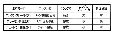
- the engine brake traveling means 52, the free-run inertia traveling means 54, and the neutral inertia traveling means 56 are for executing the three types of traveling modes shown in FIG. 3, respectively, and the engine brake traveling means 52 executes the engine brake traveling. .
- the engine brake travels while maintaining the connected state of the engine 12 and the wheel 20 when the accelerator is OFF. When all the cylinders of the engine 12 are driven and rotated, the engine brake is caused by pumping loss or friction torque. appear.
- the engine 12 may be in an idling state in which a minimum amount of fuel is supplied in the same manner as when the accelerator is OFF, but in this embodiment, the engine 12 is controlled to a fuel cut state (F / C) in which the fuel supply is stopped.
- a predetermined gear is established according to the vehicle speed V or the like, and the clutch C1 is held in the engaged state.
- the engine 12 is driven to rotate at a predetermined rotational speed determined according to the vehicle speed V and the gear ratio e, and an engine braking force having a magnitude corresponding to the rotational speed is generated.
- “Negative pressure supply” in FIG. 3 indicates whether or not negative pressure is supplied (filled) to the negative pressure tank 46 of the brake booster 42. When no negative pressure is supplied, the negative pressure tank is repeatedly operated by the brake pedal 40. The negative pressure in 46 is reduced (approaching atmospheric pressure), and the amplification effect on the brake operation force Brk is reduced.
- the free-run coasting means 54 performs free-run coasting when the accelerator is OFF.
- the clutch C1 is released to disconnect the engine 12 from the wheel 20, and fuel cut F / C for stopping the fuel supply to the engine 12 is performed, and the engine 12 is stopped in rotation. .
- the engine braking force becomes smaller than that of the engine braking and the clutch C1 is released, so that the engine braking force becomes substantially 0. Therefore, the running resistance is reduced and the running distance by inertia running is increased. , Fuel economy can be improved.
- the amplifying action of the brake operation force Brk by the brake booster 42 using the negative pressure generated by the engine rotation is reduced. In this embodiment, this free-run inertia traveling is executed as the first inertia traveling.
- the neutral inertia traveling means 56 performs neutral inertia traveling when the accelerator is OFF. Neutral coasting travels while the clutch C1 is released and the engine 12 is disconnected from the wheel 20, while fuel is supplied to the engine 12 to operate in an idling state (self-rotating). Also in this case, the engine braking force becomes smaller than that of the engine braking and the clutch C1 is disengaged, so the engine braking force becomes substantially 0. Therefore, the running resistance is reduced and the running distance by inertia running is increased. Fuel consumption can be improved.
- the travel mode switching control means 58 switches between the three types of travel modes of the engine brake travel, free-run inertia travel, and neutral inertia travel.
- the inertial running is executed according to the case classification (execution condition) shown in any of (a) to (c).
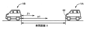
- the inter-vehicle distance X is a separation distance from the own vehicle VA to the preceding vehicle VB as shown in FIG. 2, and is sequentially measured by the inter-vehicle distance sensor 68. The shorter the inter-vehicle distance X is, the more frequently the brake operation is performed.
- the necessity of the brake negative pressure PB is increased. That is, as the inter-vehicle distance X becomes shorter, the necessity for negative pressure increases, and the first determination value ⁇ 1 and the second determination value ⁇ 1 satisfy ⁇ 1 ⁇ 1 as the inter-vehicle distance X, but the necessity for negative pressure. As a reverse relationship.
- the negative pressure necessity determination means 59 determines the necessity of negative pressure based on whether the inter-vehicle distance X is equal to or less than the first determination value ⁇ 1 and whether it is equal to or less than the second determination value ⁇ 1, and from the first determination value ⁇ 1.
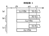
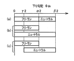
- FIG. 4 shows execution start conditions for free-run inertia running and neutral inertia running with respect to the inter-vehicle distance X.
- the running mode is switched according to the execution start conditions.
- the first determination value ⁇ 1 is a lower limit value (minimum value) of the inter-vehicle distance X when starting execution of free-run inertia running, and corresponds to an upper limit value of the necessity for negative pressure.
- the first determination value ⁇ 1 is also an upper limit value (maximum value) of the inter-vehicle distance X when starting execution of neutral inertia running, and corresponds to a lower limit value of the necessity for negative pressure.
- the second determination value ⁇ 1 is a lower limit value (minimum value) of the inter-vehicle distance X when starting execution of neutral inertia running, and corresponds to an upper limit value of the necessity for negative pressure.
- power in neutral inertia traveling, power can be generated by an alternator or the like by the rotation of the engine 12, so that the free run inertia traveling is limited according to the necessity of electric energy, such as when the remaining amount of the battery is less than a predetermined amount, and the first determination value ⁇ 1
- Various execution conditions can be set such that the neutral inertia running is executed even when it is larger. In this case, if the inter-vehicle distance X is larger than the first determination value ⁇ 1 and the inter-vehicle distance X becomes equal to or less than the first determination value ⁇ 1 during execution of the free-run inertia traveling, it is desirable to switch to the neutral inertia traveling. You may make it return to brake driving
- (c) is substantially the same as (b) ⁇ ⁇ , except that a third determination value ⁇ 1, which is the upper limit value of neutral inertia running, is set separately, and a value larger than the first determination value ⁇ 1 is set. Has been.
- a third determination value ⁇ 1 which is the upper limit value of neutral inertia running
- free-run inertia traveling is executed, and when it becomes equal to or less than the third determination value ⁇ 1, switching to neutral inertia traveling may be performed as necessary.
- Neutral inertial traveling may be executed when the third determination value ⁇ 1 or less is reached without executing inertial traveling.
- the determination values ⁇ 1 and ⁇ 1 may be predetermined values, but may be set with the road surface gradient ⁇ as a parameter as shown in FIG. 5, for example. That is, when the road surface gradient is negative, a large vehicle braking force is generally required as compared to a substantially horizontal flat road. Therefore, the determination values ⁇ 1 and ⁇ 1 are increased and the free-run coasting is performed with a large inter-vehicle distance X. The vehicle is shifted from the neutral inertia traveling mode to appropriately obtain the amplifying action of the brake operating force Brk by the brake booster 42, or to return to the engine braking traveling state to obtain a large engine braking force.
- the determination values ⁇ 1 and ⁇ 1 are reduced to perform the free run inertia running and neutral inertia running range.
- the fuel consumption can be further improved by widening.
- Such determination values ⁇ 1 and ⁇ 1 are determined in advance by a data map, an arithmetic expression, or the like.
- the third determination value ⁇ 1 may be set using the road gradient ⁇ as a parameter.
- the judgment value of the necessity of negative pressure is made small at the down slope so that it can be switched to neutral inertia running or engine brake running at a stage where the necessity of negative pressure is low. Then, the judgment value of the necessity for negative pressure is increased to make it difficult to shift to neutral inertia traveling and engine braking traveling.
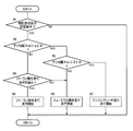
- FIG. 6 is a flowchart regarding the operation when the travel mode switching control means 58 performs execution start determination of free-running inertial traveling and neutral inertial traveling.
- steps S ⁇ b> 2 and S ⁇ b> 5 correspond to the negative pressure necessity determination unit 59 and function as a prediction unit that predicts the necessity of negative pressure based on the inter-vehicle distance X.
- step S1 it is determined whether or not a precondition for starting execution of either free-running inertia traveling or neutral inertia traveling is satisfied.
- the precondition is, for example, that the accelerator OFF (non-operation) where the accelerator operation amount ⁇ acc is substantially 0 and the brake OFF (non-operation) state where the brake operation force Brk is substantially 0 continues for a certain period of time. If the condition is satisfied, step S2 is executed.
- step S2 it is determined whether or not the inter-vehicle distance X is equal to or less than the first determination value ⁇ 1, and if X ⁇ ⁇ 1, step S5 is executed, but if X> ⁇ 1, that is, the necessity for negative pressure is low.
- step S3 is executed.
- step S3 it is determined whether or not free-run inertia traveling can be executed (appropriate). If possible or appropriate, execution of free-run inertia driving is started in step S4. On the other hand, if it is not possible or appropriate to execute the free-run inertia running, the neutral inertia running is started in step S6.
- step S ⁇ b> 3 may be omitted so that free-run inertia running is always executed when X> ⁇ ⁇ b> 1.
- step S2 determines whether the inter-vehicle distance X is equal to or smaller than the second determination value ⁇ 1, and if X> ⁇ 1, the step is performed.
- step S6 execution of neutral coasting is started.
- X ⁇ ⁇ 1 that is, when the inter-vehicle distance X is shorter than the second determination value ⁇ 1
- a large vehicle braking force may be required immediately in accordance with the brake operation, so that the inertial running is prohibited. Then, the execution of engine braking is started or continued.
- step S6 is a flowchart for explaining the operation at the start of execution of free-run inertial traveling and neutral inertial traveling.
- the inter-vehicle distance X signals are also generated in accordance with the same flowchart as in step S2 and subsequent steps even during the inertial traveling. The process is performed, and the vehicle travels while switching between the free-run inertia traveling and the neutral inertia traveling based on the inter-vehicle distance X and the possibility of execution of the free-run inertia traveling. If the determination in step S3 is NO, or if the determination in step S5 is NO, step S6 is always executed and neutral inertial running is started, but whether neutral inertial traveling is possible (appropriate) or not. If it is impossible (inappropriate), it is possible to start engine braking in step S7.
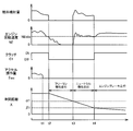
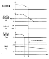
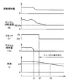
- FIG. 7 is an example of a time chart showing a change in the operating state of each part when inertial running is executed according to the flowchart of FIG. 6, and is a case of (a) or (b) ⁇ in FIG. The case of is also controlled as shown in FIG. 7 under certain conditions.
- a time t1 in FIG. 7 is a time when the accelerator is turned off, and after a predetermined time has elapsed (time t2), the clutch C1 is released (OFF) and the fuel is cut, and execution of free-run inertia running is started.
- the time t3 is the time when the inter-vehicle distance X is equal to or less than the first determination value ⁇ 1, the determination in step S2 is YES (positive), and the execution of neutral inertia traveling is started in step S6.
- the engine 12 is restarted, and the engine is brought into an idling state in which the engine speed NE is close to the idle speed NEidle. Thereafter, when the inter-vehicle distance X with the preceding vehicle increases and X> ⁇ 1 at time t4, the fuel is cut again, the engine 12 is stopped, and the free-run inertia running is resumed.
- FIG. 8 is the same as FIG. 7 until the execution of the neutral coasting is started at time t3, but the inter-vehicle distance X gradually decreases after the transition to the neutral coasting, and the inter-vehicle distance at time t4.
- the determination in step S5 is YES
- step S7 is executed, inertial traveling is released, and engine braking traveling is resumed. That is, the fuel is cut and the clutch C1 is engaged (ON), and the engine 12 is driven and rotated in accordance with the vehicle speed V and the gear ratio e of the gear stage, so that the negative pressure tank 46 is negatively pumped. As the pressure is charged, a large engine braking force is generated. Since the engine 12 is operated near the idle rotational speed NEidle in the neutral inertia traveling, the clutch C1 can be engaged relatively smoothly when shifting to the engine braking traveling.
- both free-run inertia travel and neutral inertia travel are executed as inertia travel, and the free-run inertia travel that travels with the engine 12 stopped is the inter-vehicle distance X.
- the neutral coasting traveling while the engine 12 is rotated is executed even when the inter-vehicle distance X is equal to or smaller than the first determination value ⁇ 1, that is, when the necessity for negative pressure is relatively high.
- the fuel efficiency is lower than that of the engine, it is possible to appropriately obtain the amplifying action of the brake operation force Brk by the brake booster 42 by the engine rotation, and to obtain the fuel efficiency superior to the engine brake driving while ensuring the vehicle braking force by the brake operation. It is done.
- the neutral inertial traveling is executed even when the value is equal to or less than the first determination value ⁇ 1, thereby ensuring an amplification effect of the brake operation force Brk. While improving fuel efficiency.
- the free-run inertia traveling in which excellent fuel efficiency can be obtained by traveling with the engine 12 stopped is performed when the inter-vehicle distance X is larger than the first determination value ⁇ 1 and the necessity of negative pressure is low.
- Neutral coasting where execution is started and the engine 12 is rotated and the brake booster 42 appropriately amplifies the brake operating force Brk is obtained, and the inter-vehicle distance X is equal to or less than the first determination value ⁇ 1. Since the execution is started when the necessity of the vehicle is relatively high, the vehicle control including the amplifying action of the brake operation force Brk is compared with the case where only one of the free-run inertia running and the neutral inertia running is executed. The fuel consumption can be further improved as a whole while ensuring the power appropriately.
- the vehicle shifts to the neutral inertia traveling, and the inter-vehicle distance X during the neutral inertia traveling is performed.
- the engine brake travel is resumed when becomes less than or equal to the second determination value ⁇ 1
- the amplifying action of the brake operation force Brk by the brake booster 42 can be obtained according to the inter-vehicle distance X, and further, the greater is caused by the engine brake travel. Since the engine braking force can be obtained, the fuel consumption can be further improved while appropriately securing a large vehicle braking force including the amplifying action of the brake operation force Brk according to the necessity of the negative pressure.
- free-run inertia traveling is performed as the first inertia traveling, and neutral inertia traveling is performed as the second inertia traveling.
- the clutch C1 is released and the engine braking force becomes substantially zero. Since the engine braking force is remarkably reduced as compared with traveling, the traveling distance by inertial traveling is increased and fuel efficiency is improved.
- the first determination value ⁇ 1 and the second determination value ⁇ 1 are variably set as shown in FIG. 5 according to the road surface gradient ⁇ , and are set to be larger values than the flat road on the down slope, so the inter-vehicle distance X Neutral coasting and engine braking are executed at a large stage so that the amplification effect by the brake booster 42 can be obtained quickly and a large engine braking force by engine braking can be obtained quickly.
- a large vehicle braking force can be secured on a downward slope.
- the uphill is smaller than the flat road, but the demand for the vehicle braking force is relatively small on the uphill, so free-running and neutral coasting without damaging the vehicle braking force due to braking operation.
- the execution range is widened, and the travel distance by such inertia traveling becomes longer, so that the fuel consumption is further improved.
- the execution start control of the inertia traveling shown in FIG. 6 is performed using the actual inter-vehicle distance X measured by the inter-vehicle distance sensor 68 such as a radar, but the vehicle VA and the preceding vehicle VB are controlled. It is also possible to obtain the acceleration, estimate the future inter-vehicle distance X from the acceleration difference, determine the necessity of negative pressure, and perform execution start control of inertial running.
- FIG. 9 and FIG. 10 show the case where the necessity of negative pressure is determined based on the road slope ⁇ dn.
- the frequency at which the driver performs the brake operation to suppress the increase in the vehicle speed V as the slope ⁇ dn increases.
- the necessity of the brake negative pressure PB increases.
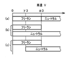
- the 10 shows execution start conditions for the three types of driving modes of engine braking, free-run inertia, and neutral inertia, according to one of the cases (a) to (c) based on the downward gradient ⁇ dn. Execution starts according to (execution conditions).
- the first determination value ⁇ 2 and the second determination value ⁇ 2 have a relationship of ⁇ 2 ⁇ 2, and have the same relationship as the necessity of negative pressure.
- the negative pressure necessity determining means 59 determines the necessity of negative pressure depending on whether the descending slope ⁇ dn is larger than the first determination value ⁇ 2 or larger than the second determination value ⁇ 2.
- FIG. 10 shows execution start conditions for free-running inertia traveling and neutral inertia traveling for the downward gradient ⁇ dn. In this embodiment, the traveling mode is switched according to the execution starting conditions.
- the second determination value ⁇ 2 or less neutral inertia traveling is executed, and when it is larger than the second determination value ⁇ 2, engine brake traveling is executed.
- the free run inertia running and the neutral inertia running are executed according to a predetermined case division below the first determination value ⁇ 2.
- a value smaller than the first determination value ⁇ 2 is set. In this case, if the third determination value ⁇ 2 or less, the free-run inertial running is executed, and if the third determination value ⁇ 2 is exceeded, it may be switched to the neutral inertial running as necessary. If the third determination value ⁇ 2 is exceeded, the neutral inertia running may be executed.
- the determination values ⁇ 2, ⁇ 2, and ⁇ 2 may be predetermined values, but may be variably set using a data map or the like that is determined in advance using the vehicle state or the traveling state as a parameter.
- FIG. 11 is a flowchart relating to the operation when the execution mode switching control means 58 performs execution start determination of free-run inertia running and neutral inertia running, which is executed instead of FIG.
- Steps R1, R3, R4, R6, and R7 in FIG. 11 are the same as steps S1, S3, S4, S6, and S7 in FIG. 6, respectively, and only steps R2 and R5 are different.
- These steps R2 and R5 correspond to the negative pressure necessity determination means 59, and function as a prediction means for predicting the necessity of negative pressure based on the downward gradient ⁇ dn.
- step R2 of FIG. 11 it is determined whether or not the downward gradient ⁇ dn exceeds the first determination value ⁇ 2, and if ⁇ dn> ⁇ 2, step R5 and subsequent steps are executed, but if ⁇ dn ⁇ ⁇ 2, that is, negative pressure If the necessity is low, step R3 and subsequent steps are executed.
- step R3 and the subsequent steps execution of free-run inertia running or neutral inertia running is started in the same manner as in the above-described embodiment.
- step R5 it is determined whether or not the downward gradient ⁇ dn exceeds the second determination value ⁇ 2, and if ⁇ dn ⁇ ⁇ 2, the neutral inertial running is started in step R6. If ⁇ dn> ⁇ 2, the engine is started.
- FIG. 11 is a flowchart for explaining the operation when starting the execution of the free-running inertial running and the neutral inertial running.
- the signals according to the same flowchart as in step R2 and after are also executed during the inertial running.
- the process is performed, and the vehicle travels while switching between the free-run inertia traveling and the neutral inertia traveling based on whether or not the down slope ⁇ dn and the free-run inertia traveling can be executed.
- step R6 is always executed and neutral inertial running is started. Whether neutral inertial traveling is possible (appropriate) or not. If it is impossible (inappropriate), it is also possible to start engine braking in step R7.
- FIG. 12 is an example of a time chart showing a change in the operating state of each part when inertial running is executed in accordance with the flowchart of FIG. 11, and is a case of (a) or (b) ⁇ in FIG. ) In the case of soot, it is controlled as shown in FIG. 12 under certain conditions.
- a time t1 in FIG. 11 is a time when the accelerator is turned off, and after a predetermined time has elapsed (time t2), the clutch C1 is released (OFF) and the fuel is cut, and execution of free-run inertia running is started.
- the time t3 is the time when the downward gradient ⁇ dn exceeds the first determination value ⁇ 2 and the determination in step R2 becomes YES (positive), and the execution of the neutral inertia running is started in step R6. 12 is restarted, and the engine is brought into an idling state in which the engine speed NE is near the idle speed NEidle. Thereafter, when the downward gradient ⁇ dn becomes smaller and ⁇ dn ⁇ ⁇ 2 at time t4, the fuel is cut again, the engine 12 is stopped, and the free-run inertia running is resumed.
- FIG. 13 is the same as FIG. 12 until the execution of the neutral inertia running is started at time t3. However, after the transition to the neutral inertia running, the descending slope ⁇ dn further increases, and the descending at time t4.
- the determination in step R5 is YES, step R7 is executed, the inertia traveling is released, and the engine braking traveling is resumed.
- the present embodiment is different from the above embodiment in that the necessity of the negative pressure is determined based on the downward slope ⁇ dn of the road surface.
- excellent fuel efficiency can be obtained by running the engine 12 while stopping the rotation.
- the obtained free-run inertial running is started when the negative gradient ⁇ dn is less necessary for the negative pressure equal to or less than the first determination value ⁇ 2, and the brake operation by the brake booster 42 is performed by running while the engine 12 is rotating.
- the neutral inertia running in which the amplifying action of the force Brk is appropriately obtained is executed when the downward gradient ⁇ dn exceeds the first determination value ⁇ 2 and the necessity of negative pressure is relatively high, the free-run inertia running and Compared with the case where only one of the neutral inertia running is executed, the fuel efficiency can be further improved as a whole while appropriately securing the amplifying action of the brake operation force Brk. For example, the same operational effects as in the above embodiment can be obtained.
- FIG. 14 shows a case where the necessity of negative pressure is determined based on the vehicle speed V.
- a greater vehicle braking force is required when the driver performs a brake operation, and the brake pedal 40 is depressed.
- the need for the brake negative pressure PB is increased in securing the vehicle braking force in this case.
- FIG. 14 shows the execution start conditions of the three types of travel modes of the engine brake travel, the free-run inertia travel, and the neutral inertia travel based on the vehicle speed V and the case classification shown in any one of (a) to (c) ( Execution starts according to the execution conditions. That is, the necessity of negative pressure is determined based on whether or not the vehicle speed V is equal to or less than the first determination value ⁇ 3.
- FIG. 14 shows execution start conditions for free-run inertia running and neutral inertia running with respect to the vehicle speed V. In this embodiment, the running mode is switched according to this execution start condition.
- the determination values ⁇ 3 and ⁇ 3 may be predetermined values, but may be variably set by a data map or the like determined in advance using the vehicle state and the traveling state as parameters.
- FIG. 15 is a flowchart relating to the operation when the execution mode switching control means 58 determines whether or not to execute free-run inertia running and neutral inertia running, and is executed instead of FIG.
- Steps Q1, Q3, Q4, and Q5 in FIG. 15 are the same as steps S1, S3, S4, and S6 in FIG. 6, respectively, and step Q2 is different.
- This step Q2 corresponds to the negative pressure necessity determination means 59 and functions as a prediction means for predicting the necessity of negative pressure based on the vehicle speed V.
- step Q2 of FIG. 15 it is determined whether or not the vehicle speed V is equal to or less than the first determination value ⁇ 3. If V ⁇ ⁇ 3, that is, if the necessity for negative pressure is low, step Q3 and subsequent steps are executed. In step Q3 and subsequent steps, the execution of free-run inertia running or neutral inertia running is started in the same manner as in the above embodiment. If V> ⁇ 3 and the determination in step Q2 is NO (negative), that is, if the need for negative pressure is high, step Q5 is immediately executed, and execution of neutral inertia running is started.
- FIG. 15 is a flowchart for explaining the operation when starting the execution of free-running inertial traveling and neutral inertial traveling.
- step Q2 signal processing is performed in accordance with the same flowchart as step Q2 and subsequent steps even during the execution of these inertial travelings.
- the vehicle travels while switching between the free-run inertia traveling and the neutral inertia traveling based on the vehicle speed V and whether or not the free-run inertia traveling can be executed.
- a second determination value ⁇ 3 larger than the first determination value ⁇ 3 is set, and when the vehicle speed V exceeds the second determination value ⁇ 3, inertial traveling is canceled and engine braking traveling is resumed. May be.
- FIG. 16 is an example of a time chart showing changes in the operating state of each part when inertial running is executed according to the flowchart of FIG. 15, and there is a possibility in any of cases (a) to (c) ⁇ in FIG. is there.
- FIG. 16 shows a case where the free-run coasting is executed when the vehicle speed V is equal to or less than the first determination value ⁇ 3, and the time t1 is the time when the accelerator is turned off, and the clutch C1 after a certain time (time t2) elapses. Is released (OFF) and fuel cut is performed, and execution of free-run inertia running is started.
- FIG. 17 shows a case where the vehicle speed V is larger than the first determination value ⁇ 3 and the neutral inertia running is executed, and there is a possibility in the case of (b) and (c) ⁇ in FIG.
- the time t1 is a time when the accelerator is turned off, and after a predetermined time has elapsed (time t2), the clutch C1 is released (OFF) and the engine 12 is controlled to be in an idling state, so that the neutral inertial running is started. Thereafter, the vehicle speed V becomes equal to or less than the first determination value ⁇ 3 at time t3.
- This example is a case where the determination in step Q3 is NO and the neutral inertia traveling is continued as it is.
- the present embodiment is different from the above embodiment in that the necessity of the negative pressure is determined based on the vehicle speed V.
- the fuel efficiency can be improved by running the engine 12 while being stopped. Run coasting is started when the need for a negative pressure with the vehicle speed V equal to or lower than the first determination value ⁇ 3 is low, and the brake booster 42 amplifies the brake operation force Brk by running while the engine 12 is rotating.
- Neutral inertial traveling with an appropriate effect is started when the vehicle speed V exceeds the first determination value ⁇ 3 and the necessity of negative pressure is relatively high, so that either free-run inertial traveling or neutral inertial traveling Compared with the case where only one of them is executed, the fuel efficiency can be further improved as a whole while appropriately amplifying the brake operation force Brk, and the like. The effect is obtained.
- neutral inertia traveling is executed as the second inertia traveling.
- cylinder rest inertia traveling may be executed instead of the neutral inertia traveling. That is, instead of the neutral inertia traveling means 56, cylinder deactivation inertia traveling means is provided so that cylinder deactivation inertia traveling is executed.
- cylinder idle coasting the fuel supply to the engine 12 is stopped (fuel cut F / C) while the engagement state of the clutch C1 is maintained and the engine 12 and the wheel 20 are connected, and the engine control device 30
- the cylinder deactivation device stops the intake / exhaust valves of a part (for example, half) of the plurality of cylinders at a position where they are closed. As a result, the distance traveled by inertial traveling is increased, and fuel efficiency is improved.
- only a part of the cylinders of the plurality of cylinders are deactivated, and the intake and exhaust valves of the remaining cylinders are opened and closed in synchronization with the crankshaft. Therefore, a negative pressure is applied to the brake booster 42 by the pumping action of these cylinders. Is supplied, and an amplifying action of the brake operation force Brk is obtained.
- the engine braking force is larger than that of the neutral inertia traveling, and the travel distance due to the inertia traveling is relatively short.
- the engine 12 since the engine 12 is only fuel-cut and driven to rotate, the fuel efficiency is neutral inertia. Efficiencies similar to or better than running can be obtained. Further, in cylinder deactivation, only a part of the cylinders and a negative pressure is generated by the pumping action for the remaining cylinders, and the amplifying action of the brake operating force Brk by the brake booster 42 is obtained as in the neutral inertia running.
- the first determination values ⁇ 1 to ⁇ 3 and the second determination regarding the execution conditions for executing the cylinder resting inertia running and the necessity of the negative pressure for starting the cylinder resting inertia running (the inter-vehicle distance X, the downward gradient ⁇ dn, the vehicle speed V)
- the values ⁇ 1 and ⁇ 2 may be the same as those in the above embodiments, but different values may be set. Further, as the second inertia traveling, the neutral inertia traveling and the cylinder deactivation inertia traveling may be executed separately for each case.
- Vehicle drive device 12 Engine 20: Wheel 42: Brake booster 46: Negative pressure tank 50: Electronic control device 52: Engine brake travel means 54: Free-run inertia travel means (first inertia travel) 56: Neutral inertia Traveling means (second inertia traveling) 58: Traveling mode switching control means 59: Negative pressure necessity determining means (predicting means) 66: Vehicle speed sensor 68: Inter-vehicle distance sensor 70: Road surface gradient sensor X: Inter-vehicle distance ⁇ dn: Downhill gradient V: Vehicle speed PB: Brake negative pressure ⁇ 1, ⁇ 2, ⁇ 3: First judgment value ⁇ 1, ⁇ 2: Second judgment value
Landscapes
- Engineering & Computer Science (AREA)
- Mechanical Engineering (AREA)
- Transportation (AREA)
- Chemical & Material Sciences (AREA)
- Combustion & Propulsion (AREA)
- Automation & Control Theory (AREA)
- General Engineering & Computer Science (AREA)
- Physics & Mathematics (AREA)
- Fluid Mechanics (AREA)
- Control Of Vehicle Engines Or Engines For Specific Uses (AREA)
- Control Of Driving Devices And Active Controlling Of Vehicle (AREA)
- Output Control And Ontrol Of Special Type Engine (AREA)
- Electrical Control Of Air Or Fuel Supplied To Internal-Combustion Engine (AREA)
- Control Of Transmission Device (AREA)
Abstract
Description
図1は、本発明が好適に適用される車両用駆動装置10の骨子図に、制御系統の要部を併せて示した概略構成図である。車両用駆動装置10は、燃料の燃焼で動力を発生するガソリンエンジンやディーゼルエンジン等の内燃機関であるエンジン12を駆動力源として備えており、そのエンジン12の出力は自動変速機16から差動歯車装置18を介して左右の車輪20に伝達される。エンジン12と自動変速機16との間には、ダンパ装置やトルクコンバータ等の動力伝達装置が設けられているが、駆動力源として機能するモータジェネレータを配設することもできる。
図9および図10は、路面の下り勾配Φdnに基づいて負圧の必要性を判断する場合で、下り勾配Φdnが大きくなる程車速Vの増加を抑えるために運転者がブレーキ操作を行う頻度が高くなり、ブレーキペダル40が踏込み操作された場合の車両制動力を確保する上で、ブレーキ負圧PBの必要性が高くなる。下り勾配Φdnは、図9に示すように水平状態(Φdn=0)から下り方向の勾配を正(+)として求めたもので、路面勾配センサ70によって測定される勾配Φから逐次算出される。図10は、前記エンジンブレーキ走行、フリーラン惰性走行、およびニュートラル惰性走行の3種類の走行モードの実行開始条件で、下り勾配Φdnに基づいて(a) ~(c) の何れかに示す場合分け(実行条件)に従って実行が開始される。第1判定値α2および第2判定値β2はα2<β2の関係を有し、負圧の必要性としても同じ関係になる。前記負圧必要性判定手段59は、下り勾配Φdnが第1判定値α2より大きいか否か、第2判定値β2より大きいか否かによって負圧の必要性を判定するもので、第1判定値α2以下の場合は負圧の必要性が低く、第1判定値α2より大きい場合は負圧の必要性が高いと判断する。また、第2判定値β2より大きい場合には、負圧の必要性が更に高いと判断する。図10は、下り勾配Φdnに関するフリーラン惰性走行およびニュートラル惰性走行の実行開始条件であるが、本実施例ではこの実行開始条件に従って走行モードが切り換えられる。
Claims (7)
- エンジンと、該エンジンの回転で負圧タンク内が負圧とされることによりブレーキ力を増幅するブレーキブースタと、を備えており、
前記エンジンと車輪とを連結したまま該エンジンの被駆動回転によりエンジンブレーキを効かせて走行するエンジンブレーキ走行、および該エンジンブレーキ走行よりもエンジンブレーキ力を低下させた状態で走行する惰性走行が可能な車両の走行制御装置において、
前記惰性走行として、前記エンジンを回転停止させて走行する第1の惰性走行、および前記エンジンを回転させたまま走行する第2の惰性走行を、それぞれ予め定められた実行条件に従って実行する一方、
前記負圧の必要性を予測する予測手段を備えているとともに、前記第1の惰性走行および前記第2の惰性走行の実行を開始する条件として該負圧の必要性が含まれており、
前記第1の惰性走行は、前記負圧の必要性が予め定められた第1判定値以下であることを条件として実行が開始されるが、前記第2の惰性走行は、該負圧の必要性が該第1判定値より高い場合でも実行が開始される
ことを特徴とする車両の走行制御装置。 - 前記予測手段は、先行車両との車間距離、路面の勾配、および車速の少なくとも一つに基づいて前記負圧の必要性を予測するもので、該車間距離が短い程該負圧の必要性が高いと予測し、該路面の下り勾配が大きい程該負圧の必要性が高いと予測し、該車速が高い程該負圧の必要性が高いと予測する
ことを特徴とする請求項1に記載の車両の走行制御装置。 - 前記第2の惰性走行は、前記負圧の必要性が前記第1判定値よりも高い予め定められた第2判定値以下の場合に実行が開始される
ことを特徴とする請求項1または2に記載の車両の走行制御装置。 - 前記第2の惰性走行は、前記負圧の必要性が前記第1判定値を超え且つ前記第2判定値以下の領域で実行が開始される
ことを特徴とする請求項3に記載の車両の走行制御装置。 - 前記第2の惰性走行は、前記負圧の必要性が前記第1判定値以下の領域を含めて前記第2判定値以下の領域で実行を開始することが可能で、
前記第1判定値以下の重複領域では、前記第1の惰性走行および前記第2の惰性走行の何れか一方が選択されて実行が開始される
ことを特徴とする請求項3に記載の車両の走行制御装置。 - 前記第1の惰性走行は、前記エンジンを前記車輪から切り離すとともに該エンジンに対する燃料供給を停止して回転停止させるフリーラン惰性走行で、
前記第2の惰性走行は、前記エンジンを前記車輪から切り離した状態で該エンジンに燃料を供給して作動させるニュートラル惰性走行である
ことを特徴とする請求項1~5の何れか1項に記載の車両の走行制御装置。 - 前記第1の惰性走行は、前記エンジンを前記車輪から切り離すとともに該エンジンに対する燃料供給を停止して回転停止させるフリーラン惰性走行で、
前記第2の惰性走行は、前記エンジンと前記車輪とを連結したまま該エンジンに対する燃料供給を停止するとともに、該エンジンの複数の気筒の中の一部の気筒のピストンおよび吸排気弁の少なくとも一方の動作を停止させる気筒休止惰性走行である
ことを特徴とする請求項1~5の何れか1項に記載の車両の走行制御装置。
Priority Applications (5)
| Application Number | Priority Date | Filing Date | Title |
|---|---|---|---|
| JP2014544137A JP5900640B2 (ja) | 2012-10-31 | 2012-10-31 | 車両の走行制御装置 |
| EP12887501.0A EP2915713B1 (en) | 2012-10-31 | 2012-10-31 | Vehicle travel control device |
| PCT/JP2012/078230 WO2014068722A1 (ja) | 2012-10-31 | 2012-10-31 | 車両の走行制御装置 |
| US14/439,384 US9623870B2 (en) | 2012-10-31 | 2012-10-31 | Vehicle travel control device |
| CN201280076816.1A CN104768819B (zh) | 2012-10-31 | 2012-10-31 | 车辆的行驶控制装置 |
Applications Claiming Priority (1)
| Application Number | Priority Date | Filing Date | Title |
|---|---|---|---|
| PCT/JP2012/078230 WO2014068722A1 (ja) | 2012-10-31 | 2012-10-31 | 車両の走行制御装置 |
Publications (1)
| Publication Number | Publication Date |
|---|---|
| WO2014068722A1 true WO2014068722A1 (ja) | 2014-05-08 |
Family
ID=50626689
Family Applications (1)
| Application Number | Title | Priority Date | Filing Date |
|---|---|---|---|
| PCT/JP2012/078230 Ceased WO2014068722A1 (ja) | 2012-10-31 | 2012-10-31 | 車両の走行制御装置 |
Country Status (5)
| Country | Link |
|---|---|
| US (1) | US9623870B2 (ja) |
| EP (1) | EP2915713B1 (ja) |
| JP (1) | JP5900640B2 (ja) |
| CN (1) | CN104768819B (ja) |
| WO (1) | WO2014068722A1 (ja) |
Cited By (16)
| Publication number | Priority date | Publication date | Assignee | Title |
|---|---|---|---|---|
| JP2016107772A (ja) * | 2014-12-05 | 2016-06-20 | 日立オートモティブシステムズ株式会社 | 車両制御装置 |
| JP2016117307A (ja) * | 2014-12-18 | 2016-06-30 | トヨタ自動車株式会社 | 車両制御装置 |
| JP2016141288A (ja) * | 2015-02-03 | 2016-08-08 | トヨタ自動車株式会社 | 車両制御装置 |
| JP2016193676A (ja) * | 2015-04-01 | 2016-11-17 | トヨタ自動車株式会社 | 車両の制御装置 |
| CN106143477A (zh) * | 2015-03-25 | 2016-11-23 | 比亚迪股份有限公司 | 混合动力汽车及其驱动控制方法和装置 |
| CN106143476A (zh) * | 2015-03-25 | 2016-11-23 | 比亚迪股份有限公司 | 混合动力汽车及其驱动控制方法和装置 |
| CN106143479A (zh) * | 2015-03-25 | 2016-11-23 | 比亚迪股份有限公司 | 混合动力汽车及其驱动控制方法和装置 |
| JP2016210222A (ja) * | 2015-04-30 | 2016-12-15 | トヨタ自動車株式会社 | 車両の制御装置 |
| JP2017020386A (ja) * | 2015-07-08 | 2017-01-26 | トヨタ自動車株式会社 | 車両の制御装置 |
| JP2017022911A (ja) * | 2015-07-13 | 2017-01-26 | 三菱自動車工業株式会社 | 車両の制御装置 |
| US9598084B2 (en) | 2012-10-31 | 2017-03-21 | Toyota Jidosha Kabushiki Kaisha | Vehicle travel controller |
| US9604644B2 (en) | 2012-08-08 | 2017-03-28 | Toyota Jidosha Kabushiki Kaisha | Running control system for vehicle |
| JP2017094805A (ja) * | 2015-11-19 | 2017-06-01 | 株式会社デンソー | 車両制御装置 |
| JP2017114352A (ja) * | 2015-12-25 | 2017-06-29 | 日立オートモティブシステムズ株式会社 | 運転支援制御装置 |
| JP2018059636A (ja) * | 2017-12-26 | 2018-04-12 | 日立オートモティブシステムズ株式会社 | 車両用制御装置 |
| JPWO2019044275A1 (ja) * | 2017-08-27 | 2019-11-07 | 寛治 泉 | 自動車慣性走行制御システム。 |
Families Citing this family (21)
| Publication number | Priority date | Publication date | Assignee | Title |
|---|---|---|---|---|
| JP5935886B2 (ja) | 2012-06-20 | 2016-06-15 | トヨタ自動車株式会社 | 車両の制御装置 |
| JP5741551B2 (ja) | 2012-10-24 | 2015-07-01 | トヨタ自動車株式会社 | 車両の走行制御装置 |
| DE112012007067B4 (de) * | 2012-10-31 | 2018-06-28 | Toyota Jidosha Kabushiki Kaisha | Fahrzeugfahrt-Steuerungsvorrichtung |
| US9409576B2 (en) | 2012-10-31 | 2016-08-09 | Toyota Jidosha Kabushiki Kaisha | Vehicle travel controller |
| CN104768818B (zh) * | 2012-10-31 | 2017-04-05 | 丰田自动车株式会社 | 车辆的行驶控制装置 |
| WO2014068723A1 (ja) * | 2012-10-31 | 2014-05-08 | トヨタ自動車株式会社 | 車両の走行制御装置 |
| EP2995836B1 (en) | 2013-05-07 | 2020-04-08 | Toyota Jidosha Kabushiki Kaisha | Shift control device for vehicle |
| BR112016001989B1 (pt) * | 2013-09-11 | 2022-03-29 | Scania Cv Ab | Método de controle de um motor de combustão para desacelerar um veiculo |
| JP6142854B2 (ja) * | 2014-08-20 | 2017-06-07 | トヨタ自動車株式会社 | 車両制御装置及び車両制御方法 |
| KR101588759B1 (ko) * | 2014-09-22 | 2016-02-12 | 현대자동차 주식회사 | 차량용 변속 제어 장치 및 방법 |
| JP6437891B2 (ja) * | 2015-07-03 | 2018-12-12 | 日立オートモティブシステムズ株式会社 | 自動車の制御装置 |
| JP6414133B2 (ja) * | 2016-04-28 | 2018-10-31 | トヨタ自動車株式会社 | 車両制御装置 |
| US9766629B1 (en) * | 2016-09-12 | 2017-09-19 | Ford Global Technologies, Llc | Autonomous pulse and glide system |
| DE102016223279A1 (de) * | 2016-11-24 | 2018-05-24 | Volkswagen Aktiengesellschaft | Verfahren zum Betreiben eines Kraftfahrzeugs und Kraftfahrzeug |
| JP6188110B1 (ja) * | 2017-01-04 | 2017-08-30 | 寛治 泉 | 自動車慣性走行制御システム。 |
| US10134276B1 (en) | 2017-12-01 | 2018-11-20 | International Business Machines Corporation | Traffic intersection distance anayltics system |
| JP7574596B2 (ja) * | 2020-09-30 | 2024-10-29 | 株式会社アドヴィックス | 制動制御装置 |
| KR102410865B1 (ko) * | 2020-12-22 | 2022-06-23 | 주식회사 현대케피코 | 타력주행 모드 자동 해제 방법 및 차량 |
| US11491983B1 (en) | 2021-06-04 | 2022-11-08 | Hyundai Motor Company | Vehicle coasting optimization |
| KR20230013222A (ko) * | 2021-07-16 | 2023-01-26 | 현대자동차주식회사 | 전방 차량과의 차간 거리 제어 장치 및 방법 |
| EP4600099A1 (en) * | 2024-02-06 | 2025-08-13 | Volvo Truck Corporation | System and method for controlling a powertrain system of a vehicle |
Citations (5)
| Publication number | Priority date | Publication date | Assignee | Title |
|---|---|---|---|---|
| JP2002227885A (ja) | 2001-02-06 | 2002-08-14 | Hino Motors Ltd | クラッチ制御装置 |
| JP2004251279A (ja) * | 2003-02-21 | 2004-09-09 | Robert Bosch Gmbh | 車両の駆動ユニットの制御方法及び装置 |
| JP2011173475A (ja) * | 2010-02-23 | 2011-09-08 | Toyota Motor Corp | 車両制御システム |
| WO2011135725A1 (ja) * | 2010-04-30 | 2011-11-03 | トヨタ自動車株式会社 | 車両制御システム |
| WO2012111062A1 (ja) * | 2011-02-14 | 2012-08-23 | トヨタ自動車株式会社 | 車両制御装置 |
Family Cites Families (16)
| Publication number | Priority date | Publication date | Assignee | Title |
|---|---|---|---|---|
| US5961418A (en) | 1996-10-25 | 1999-10-05 | Aisin Aw Co., Ltd. | Infinitely variable transmission |
| JP3376892B2 (ja) | 1996-10-25 | 2003-02-10 | アイシン・エィ・ダブリュ株式会社 | 無段変速機 |
| JP3967536B2 (ja) * | 1999-11-25 | 2007-08-29 | トヨタ自動車株式会社 | 可変動弁機構を有する内燃機関 |
| DE10229035B4 (de) * | 2002-06-28 | 2015-10-15 | Robert Bosch Gmbh | Verfahren zur Steuerung der Antriebseinheit eines Fahrzeugs |
| JP2005226701A (ja) | 2004-02-12 | 2005-08-25 | Nissan Diesel Motor Co Ltd | 車両の制御装置 |
| JP2007126092A (ja) | 2005-11-07 | 2007-05-24 | Nissan Motor Co Ltd | ハイブリッド車両のコースティング走行時制動力制御装置 |
| WO2010137408A1 (ja) * | 2009-05-26 | 2010-12-02 | 日産自動車株式会社 | 車両の制御装置および制御方法 |
| JP5177162B2 (ja) | 2010-03-30 | 2013-04-03 | アイシン・エィ・ダブリュ株式会社 | 自動変速機の制御装置 |
| DE102010031036A1 (de) * | 2010-07-07 | 2012-01-12 | Robert Bosch Gmbh | Verfahren und Vorrichtung zur Kupplungssteuerung im Segelbetrieb eines Kraftfahrzeugs |
| WO2013093962A1 (ja) | 2011-12-20 | 2013-06-27 | トヨタ自動車株式会社 | 車両の制御装置 |
| JP5935886B2 (ja) | 2012-06-20 | 2016-06-15 | トヨタ自動車株式会社 | 車両の制御装置 |
| JP6107824B2 (ja) | 2012-08-08 | 2017-04-05 | トヨタ自動車株式会社 | 車両の走行制御装置 |
| JP5741551B2 (ja) | 2012-10-24 | 2015-07-01 | トヨタ自動車株式会社 | 車両の走行制御装置 |
| WO2014068719A1 (ja) | 2012-10-31 | 2014-05-08 | トヨタ自動車株式会社 | 車両の走行制御装置 |
| US9409576B2 (en) | 2012-10-31 | 2016-08-09 | Toyota Jidosha Kabushiki Kaisha | Vehicle travel controller |
| EP2995836B1 (en) | 2013-05-07 | 2020-04-08 | Toyota Jidosha Kabushiki Kaisha | Shift control device for vehicle |
-
2012
- 2012-10-31 JP JP2014544137A patent/JP5900640B2/ja active Active
- 2012-10-31 US US14/439,384 patent/US9623870B2/en not_active Expired - Fee Related
- 2012-10-31 EP EP12887501.0A patent/EP2915713B1/en active Active
- 2012-10-31 WO PCT/JP2012/078230 patent/WO2014068722A1/ja not_active Ceased
- 2012-10-31 CN CN201280076816.1A patent/CN104768819B/zh not_active Expired - Fee Related
Patent Citations (5)
| Publication number | Priority date | Publication date | Assignee | Title |
|---|---|---|---|---|
| JP2002227885A (ja) | 2001-02-06 | 2002-08-14 | Hino Motors Ltd | クラッチ制御装置 |
| JP2004251279A (ja) * | 2003-02-21 | 2004-09-09 | Robert Bosch Gmbh | 車両の駆動ユニットの制御方法及び装置 |
| JP2011173475A (ja) * | 2010-02-23 | 2011-09-08 | Toyota Motor Corp | 車両制御システム |
| WO2011135725A1 (ja) * | 2010-04-30 | 2011-11-03 | トヨタ自動車株式会社 | 車両制御システム |
| WO2012111062A1 (ja) * | 2011-02-14 | 2012-08-23 | トヨタ自動車株式会社 | 車両制御装置 |
Non-Patent Citations (1)
| Title |
|---|
| See also references of EP2915713A4 |
Cited By (18)
| Publication number | Priority date | Publication date | Assignee | Title |
|---|---|---|---|---|
| US9604644B2 (en) | 2012-08-08 | 2017-03-28 | Toyota Jidosha Kabushiki Kaisha | Running control system for vehicle |
| US9598084B2 (en) | 2012-10-31 | 2017-03-21 | Toyota Jidosha Kabushiki Kaisha | Vehicle travel controller |
| JP2016107772A (ja) * | 2014-12-05 | 2016-06-20 | 日立オートモティブシステムズ株式会社 | 車両制御装置 |
| JP2016117307A (ja) * | 2014-12-18 | 2016-06-30 | トヨタ自動車株式会社 | 車両制御装置 |
| JP2016141288A (ja) * | 2015-02-03 | 2016-08-08 | トヨタ自動車株式会社 | 車両制御装置 |
| CN106143477B (zh) * | 2015-03-25 | 2019-03-29 | 比亚迪股份有限公司 | 混合动力汽车及其驱动控制方法和装置 |
| CN106143477A (zh) * | 2015-03-25 | 2016-11-23 | 比亚迪股份有限公司 | 混合动力汽车及其驱动控制方法和装置 |
| CN106143476A (zh) * | 2015-03-25 | 2016-11-23 | 比亚迪股份有限公司 | 混合动力汽车及其驱动控制方法和装置 |
| CN106143479A (zh) * | 2015-03-25 | 2016-11-23 | 比亚迪股份有限公司 | 混合动力汽车及其驱动控制方法和装置 |
| CN106143479B (zh) * | 2015-03-25 | 2019-04-19 | 比亚迪股份有限公司 | 混合动力汽车及其驱动控制方法和装置 |
| JP2016193676A (ja) * | 2015-04-01 | 2016-11-17 | トヨタ自動車株式会社 | 車両の制御装置 |
| JP2016210222A (ja) * | 2015-04-30 | 2016-12-15 | トヨタ自動車株式会社 | 車両の制御装置 |
| JP2017020386A (ja) * | 2015-07-08 | 2017-01-26 | トヨタ自動車株式会社 | 車両の制御装置 |
| JP2017022911A (ja) * | 2015-07-13 | 2017-01-26 | 三菱自動車工業株式会社 | 車両の制御装置 |
| JP2017094805A (ja) * | 2015-11-19 | 2017-06-01 | 株式会社デンソー | 車両制御装置 |
| JP2017114352A (ja) * | 2015-12-25 | 2017-06-29 | 日立オートモティブシステムズ株式会社 | 運転支援制御装置 |
| JPWO2019044275A1 (ja) * | 2017-08-27 | 2019-11-07 | 寛治 泉 | 自動車慣性走行制御システム。 |
| JP2018059636A (ja) * | 2017-12-26 | 2018-04-12 | 日立オートモティブシステムズ株式会社 | 車両用制御装置 |
Also Published As
| Publication number | Publication date |
|---|---|
| CN104768819B (zh) | 2017-11-24 |
| JPWO2014068722A1 (ja) | 2016-09-08 |
| CN104768819A (zh) | 2015-07-08 |
| EP2915713B1 (en) | 2019-12-18 |
| EP2915713A4 (en) | 2016-08-10 |
| JP5900640B2 (ja) | 2016-04-06 |
| EP2915713A1 (en) | 2015-09-09 |
| US9623870B2 (en) | 2017-04-18 |
| US20150307103A1 (en) | 2015-10-29 |
Similar Documents
| Publication | Publication Date | Title |
|---|---|---|
| JP5900640B2 (ja) | 車両の走行制御装置 | |
| JP5741551B2 (ja) | 車両の走行制御装置 | |
| JP6003999B2 (ja) | 車両の走行制御装置 | |
| JP5962767B2 (ja) | 車両の走行制御装置 | |
| JP5704148B2 (ja) | 車両の走行制御装置 | |
| JP5900641B2 (ja) | 車両の走行制御装置 | |
| JP5724985B2 (ja) | 車両の走行制御装置 | |
| JP5900642B2 (ja) | 車両の走行制御装置 | |
| JPWO2014068720A1 (ja) | 車両の走行制御装置 | |
| JP2014091398A (ja) | 車両の走行制御装置 | |
| JP5949936B2 (ja) | 車両の走行制御装置 | |
| JP2014091338A (ja) | 車両の走行制御装置 | |
| JP2014088825A (ja) | 車両の走行制御装置 | |
| JP2014092103A (ja) | 車両の走行制御装置 |
Legal Events
| Date | Code | Title | Description |
|---|---|---|---|
| 121 | Ep: the epo has been informed by wipo that ep was designated in this application |
Ref document number: 12887501 Country of ref document: EP Kind code of ref document: A1 |
|
| ENP | Entry into the national phase |
Ref document number: 2014544137 Country of ref document: JP Kind code of ref document: A |
|
| WWE | Wipo information: entry into national phase |
Ref document number: 14439384 Country of ref document: US |
|
| NENP | Non-entry into the national phase |
Ref country code: DE |
|
| WWE | Wipo information: entry into national phase |
Ref document number: 2012887501 Country of ref document: EP |