WO2014068733A1 - Chargeur rapide pour un véhicule électrique - Google Patents
Chargeur rapide pour un véhicule électrique Download PDFInfo
- Publication number
- WO2014068733A1 WO2014068733A1 PCT/JP2012/078248 JP2012078248W WO2014068733A1 WO 2014068733 A1 WO2014068733 A1 WO 2014068733A1 JP 2012078248 W JP2012078248 W JP 2012078248W WO 2014068733 A1 WO2014068733 A1 WO 2014068733A1
- Authority
- WO
- WIPO (PCT)
- Prior art keywords
- power
- electric vehicle
- storage battery
- power source
- quick charger
- Prior art date
- Legal status (The legal status is an assumption and is not a legal conclusion. Google has not performed a legal analysis and makes no representation as to the accuracy of the status listed.)
- Ceased
Links
Images

Classifications
-
- H—ELECTRICITY
- H02—GENERATION; CONVERSION OR DISTRIBUTION OF ELECTRIC POWER
- H02J—ELECTRIC POWER NETWORKS; CIRCUIT ARRANGEMENTS OR SYSTEMS FOR SUPPLYING OR DISTRIBUTING ELECTRIC POWER; SYSTEMS FOR STORING ELECTRIC ENERGY
- H02J7/00—Circuit arrangements for charging or discharging batteries or for supplying loads from batteries
- H02J7/34—Parallel operation in networks using both storage and other DC sources, e.g. providing buffering
- H02J7/35—Parallel operation in networks using both storage and other DC sources, e.g. providing buffering with light sensitive cells
-
- B—PERFORMING OPERATIONS; TRANSPORTING
- B60—VEHICLES IN GENERAL
- B60L—PROPULSION OF ELECTRICALLY-PROPELLED VEHICLES; SUPPLYING ELECTRIC POWER FOR AUXILIARY EQUIPMENT OF ELECTRICALLY-PROPELLED VEHICLES; ELECTRODYNAMIC BRAKE SYSTEMS FOR VEHICLES IN GENERAL; MAGNETIC SUSPENSION OR LEVITATION FOR VEHICLES; MONITORING OPERATING VARIABLES OF ELECTRICALLY-PROPELLED VEHICLES; ELECTRIC SAFETY DEVICES FOR ELECTRICALLY-PROPELLED VEHICLES
- B60L50/00—Electric propulsion with power supplied within the vehicle
- B60L50/10—Electric propulsion with power supplied within the vehicle using propulsion power supplied by engine-driven generators, e.g. generators driven by combustion engines
- B60L50/16—Electric propulsion with power supplied within the vehicle using propulsion power supplied by engine-driven generators, e.g. generators driven by combustion engines with provision for separate direct mechanical propulsion
-
- B—PERFORMING OPERATIONS; TRANSPORTING
- B60—VEHICLES IN GENERAL
- B60L—PROPULSION OF ELECTRICALLY-PROPELLED VEHICLES; SUPPLYING ELECTRIC POWER FOR AUXILIARY EQUIPMENT OF ELECTRICALLY-PROPELLED VEHICLES; ELECTRODYNAMIC BRAKE SYSTEMS FOR VEHICLES IN GENERAL; MAGNETIC SUSPENSION OR LEVITATION FOR VEHICLES; MONITORING OPERATING VARIABLES OF ELECTRICALLY-PROPELLED VEHICLES; ELECTRIC SAFETY DEVICES FOR ELECTRICALLY-PROPELLED VEHICLES
- B60L53/00—Methods of charging batteries, specially adapted for electric vehicles; Charging stations or on-board charging equipment therefor; Exchange of energy storage elements in electric vehicles
- B60L53/10—Methods of charging batteries, specially adapted for electric vehicles; Charging stations or on-board charging equipment therefor; Exchange of energy storage elements in electric vehicles characterised by the energy transfer between the charging station and the vehicle
- B60L53/11—DC charging controlled by the charging station, e.g. mode 4
-
- B—PERFORMING OPERATIONS; TRANSPORTING
- B60—VEHICLES IN GENERAL
- B60L—PROPULSION OF ELECTRICALLY-PROPELLED VEHICLES; SUPPLYING ELECTRIC POWER FOR AUXILIARY EQUIPMENT OF ELECTRICALLY-PROPELLED VEHICLES; ELECTRODYNAMIC BRAKE SYSTEMS FOR VEHICLES IN GENERAL; MAGNETIC SUSPENSION OR LEVITATION FOR VEHICLES; MONITORING OPERATING VARIABLES OF ELECTRICALLY-PROPELLED VEHICLES; ELECTRIC SAFETY DEVICES FOR ELECTRICALLY-PROPELLED VEHICLES
- B60L53/00—Methods of charging batteries, specially adapted for electric vehicles; Charging stations or on-board charging equipment therefor; Exchange of energy storage elements in electric vehicles
- B60L53/10—Methods of charging batteries, specially adapted for electric vehicles; Charging stations or on-board charging equipment therefor; Exchange of energy storage elements in electric vehicles characterised by the energy transfer between the charging station and the vehicle
- B60L53/14—Conductive energy transfer
-
- B—PERFORMING OPERATIONS; TRANSPORTING
- B60—VEHICLES IN GENERAL
- B60L—PROPULSION OF ELECTRICALLY-PROPELLED VEHICLES; SUPPLYING ELECTRIC POWER FOR AUXILIARY EQUIPMENT OF ELECTRICALLY-PROPELLED VEHICLES; ELECTRODYNAMIC BRAKE SYSTEMS FOR VEHICLES IN GENERAL; MAGNETIC SUSPENSION OR LEVITATION FOR VEHICLES; MONITORING OPERATING VARIABLES OF ELECTRICALLY-PROPELLED VEHICLES; ELECTRIC SAFETY DEVICES FOR ELECTRICALLY-PROPELLED VEHICLES
- B60L53/00—Methods of charging batteries, specially adapted for electric vehicles; Charging stations or on-board charging equipment therefor; Exchange of energy storage elements in electric vehicles
- B60L53/30—Constructional details of charging stations
- B60L53/305—Communication interfaces
-
- B—PERFORMING OPERATIONS; TRANSPORTING
- B60—VEHICLES IN GENERAL
- B60L—PROPULSION OF ELECTRICALLY-PROPELLED VEHICLES; SUPPLYING ELECTRIC POWER FOR AUXILIARY EQUIPMENT OF ELECTRICALLY-PROPELLED VEHICLES; ELECTRODYNAMIC BRAKE SYSTEMS FOR VEHICLES IN GENERAL; MAGNETIC SUSPENSION OR LEVITATION FOR VEHICLES; MONITORING OPERATING VARIABLES OF ELECTRICALLY-PROPELLED VEHICLES; ELECTRIC SAFETY DEVICES FOR ELECTRICALLY-PROPELLED VEHICLES
- B60L53/00—Methods of charging batteries, specially adapted for electric vehicles; Charging stations or on-board charging equipment therefor; Exchange of energy storage elements in electric vehicles
- B60L53/50—Charging stations characterised by energy-storage or power-generation means
- B60L53/51—Photovoltaic means
-
- B—PERFORMING OPERATIONS; TRANSPORTING
- B60—VEHICLES IN GENERAL
- B60L—PROPULSION OF ELECTRICALLY-PROPELLED VEHICLES; SUPPLYING ELECTRIC POWER FOR AUXILIARY EQUIPMENT OF ELECTRICALLY-PROPELLED VEHICLES; ELECTRODYNAMIC BRAKE SYSTEMS FOR VEHICLES IN GENERAL; MAGNETIC SUSPENSION OR LEVITATION FOR VEHICLES; MONITORING OPERATING VARIABLES OF ELECTRICALLY-PROPELLED VEHICLES; ELECTRIC SAFETY DEVICES FOR ELECTRICALLY-PROPELLED VEHICLES
- B60L53/00—Methods of charging batteries, specially adapted for electric vehicles; Charging stations or on-board charging equipment therefor; Exchange of energy storage elements in electric vehicles
- B60L53/50—Charging stations characterised by energy-storage or power-generation means
- B60L53/53—Batteries
-
- H—ELECTRICITY
- H02—GENERATION; CONVERSION OR DISTRIBUTION OF ELECTRIC POWER
- H02J—ELECTRIC POWER NETWORKS; CIRCUIT ARRANGEMENTS OR SYSTEMS FOR SUPPLYING OR DISTRIBUTING ELECTRIC POWER; SYSTEMS FOR STORING ELECTRIC ENERGY
- H02J7/00—Circuit arrangements for charging or discharging batteries or for supplying loads from batteries
- H02J7/34—Parallel operation in networks using both storage and other DC sources, e.g. providing buffering
- H02J7/342—The other DC source being a battery actively interacting with the first one, i.e. battery to battery charging
-
- B—PERFORMING OPERATIONS; TRANSPORTING
- B60—VEHICLES IN GENERAL
- B60L—PROPULSION OF ELECTRICALLY-PROPELLED VEHICLES; SUPPLYING ELECTRIC POWER FOR AUXILIARY EQUIPMENT OF ELECTRICALLY-PROPELLED VEHICLES; ELECTRODYNAMIC BRAKE SYSTEMS FOR VEHICLES IN GENERAL; MAGNETIC SUSPENSION OR LEVITATION FOR VEHICLES; MONITORING OPERATING VARIABLES OF ELECTRICALLY-PROPELLED VEHICLES; ELECTRIC SAFETY DEVICES FOR ELECTRICALLY-PROPELLED VEHICLES
- B60L2210/00—Converter types
- B60L2210/10—DC to DC converters
-
- B—PERFORMING OPERATIONS; TRANSPORTING
- B60—VEHICLES IN GENERAL
- B60L—PROPULSION OF ELECTRICALLY-PROPELLED VEHICLES; SUPPLYING ELECTRIC POWER FOR AUXILIARY EQUIPMENT OF ELECTRICALLY-PROPELLED VEHICLES; ELECTRODYNAMIC BRAKE SYSTEMS FOR VEHICLES IN GENERAL; MAGNETIC SUSPENSION OR LEVITATION FOR VEHICLES; MONITORING OPERATING VARIABLES OF ELECTRICALLY-PROPELLED VEHICLES; ELECTRIC SAFETY DEVICES FOR ELECTRICALLY-PROPELLED VEHICLES
- B60L2210/00—Converter types
- B60L2210/30—AC to DC converters
-
- H—ELECTRICITY
- H02—GENERATION; CONVERSION OR DISTRIBUTION OF ELECTRIC POWER
- H02J—ELECTRIC POWER NETWORKS; CIRCUIT ARRANGEMENTS OR SYSTEMS FOR SUPPLYING OR DISTRIBUTING ELECTRIC POWER; SYSTEMS FOR STORING ELECTRIC ENERGY
- H02J2105/00—Networks for supplying or distributing electric power characterised by their spatial reach or by the load
- H02J2105/30—Networks for supplying or distributing electric power characterised by their spatial reach or by the load the load networks being external to vehicles, i.e. exchanging power with vehicles
- H02J2105/33—Networks for supplying or distributing electric power characterised by their spatial reach or by the load the load networks being external to vehicles, i.e. exchanging power with vehicles exchanging power with road vehicles
- H02J2105/37—Networks for supplying or distributing electric power characterised by their spatial reach or by the load the load networks being external to vehicles, i.e. exchanging power with vehicles exchanging power with road vehicles exchanging power with electric vehicles [EV] or with hybrid electric vehicles [HEV]
-
- Y—GENERAL TAGGING OF NEW TECHNOLOGICAL DEVELOPMENTS; GENERAL TAGGING OF CROSS-SECTIONAL TECHNOLOGIES SPANNING OVER SEVERAL SECTIONS OF THE IPC; TECHNICAL SUBJECTS COVERED BY FORMER USPC CROSS-REFERENCE ART COLLECTIONS [XRACs] AND DIGESTS
- Y02—TECHNOLOGIES OR APPLICATIONS FOR MITIGATION OR ADAPTATION AGAINST CLIMATE CHANGE
- Y02T—CLIMATE CHANGE MITIGATION TECHNOLOGIES RELATED TO TRANSPORTATION
- Y02T10/00—Road transport of goods or passengers
- Y02T10/60—Other road transportation technologies with climate change mitigation effect
- Y02T10/70—Energy storage systems for electromobility, e.g. batteries
-
- Y—GENERAL TAGGING OF NEW TECHNOLOGICAL DEVELOPMENTS; GENERAL TAGGING OF CROSS-SECTIONAL TECHNOLOGIES SPANNING OVER SEVERAL SECTIONS OF THE IPC; TECHNICAL SUBJECTS COVERED BY FORMER USPC CROSS-REFERENCE ART COLLECTIONS [XRACs] AND DIGESTS
- Y02—TECHNOLOGIES OR APPLICATIONS FOR MITIGATION OR ADAPTATION AGAINST CLIMATE CHANGE
- Y02T—CLIMATE CHANGE MITIGATION TECHNOLOGIES RELATED TO TRANSPORTATION
- Y02T10/00—Road transport of goods or passengers
- Y02T10/60—Other road transportation technologies with climate change mitigation effect
- Y02T10/7072—Electromobility specific charging systems or methods for batteries, ultracapacitors, supercapacitors or double-layer capacitors
-
- Y—GENERAL TAGGING OF NEW TECHNOLOGICAL DEVELOPMENTS; GENERAL TAGGING OF CROSS-SECTIONAL TECHNOLOGIES SPANNING OVER SEVERAL SECTIONS OF THE IPC; TECHNICAL SUBJECTS COVERED BY FORMER USPC CROSS-REFERENCE ART COLLECTIONS [XRACs] AND DIGESTS
- Y02—TECHNOLOGIES OR APPLICATIONS FOR MITIGATION OR ADAPTATION AGAINST CLIMATE CHANGE
- Y02T—CLIMATE CHANGE MITIGATION TECHNOLOGIES RELATED TO TRANSPORTATION
- Y02T10/00—Road transport of goods or passengers
- Y02T10/60—Other road transportation technologies with climate change mitigation effect
- Y02T10/72—Electric energy management in electromobility
-
- Y—GENERAL TAGGING OF NEW TECHNOLOGICAL DEVELOPMENTS; GENERAL TAGGING OF CROSS-SECTIONAL TECHNOLOGIES SPANNING OVER SEVERAL SECTIONS OF THE IPC; TECHNICAL SUBJECTS COVERED BY FORMER USPC CROSS-REFERENCE ART COLLECTIONS [XRACs] AND DIGESTS
- Y02—TECHNOLOGIES OR APPLICATIONS FOR MITIGATION OR ADAPTATION AGAINST CLIMATE CHANGE
- Y02T—CLIMATE CHANGE MITIGATION TECHNOLOGIES RELATED TO TRANSPORTATION
- Y02T90/00—Enabling technologies or technologies with a potential or indirect contribution to GHG emissions mitigation
- Y02T90/10—Technologies relating to charging of electric vehicles
- Y02T90/12—Electric charging stations
-
- Y—GENERAL TAGGING OF NEW TECHNOLOGICAL DEVELOPMENTS; GENERAL TAGGING OF CROSS-SECTIONAL TECHNOLOGIES SPANNING OVER SEVERAL SECTIONS OF THE IPC; TECHNICAL SUBJECTS COVERED BY FORMER USPC CROSS-REFERENCE ART COLLECTIONS [XRACs] AND DIGESTS
- Y02—TECHNOLOGIES OR APPLICATIONS FOR MITIGATION OR ADAPTATION AGAINST CLIMATE CHANGE
- Y02T—CLIMATE CHANGE MITIGATION TECHNOLOGIES RELATED TO TRANSPORTATION
- Y02T90/00—Enabling technologies or technologies with a potential or indirect contribution to GHG emissions mitigation
- Y02T90/10—Technologies relating to charging of electric vehicles
- Y02T90/14—Plug-in electric vehicles
-
- Y—GENERAL TAGGING OF NEW TECHNOLOGICAL DEVELOPMENTS; GENERAL TAGGING OF CROSS-SECTIONAL TECHNOLOGIES SPANNING OVER SEVERAL SECTIONS OF THE IPC; TECHNICAL SUBJECTS COVERED BY FORMER USPC CROSS-REFERENCE ART COLLECTIONS [XRACs] AND DIGESTS
- Y02—TECHNOLOGIES OR APPLICATIONS FOR MITIGATION OR ADAPTATION AGAINST CLIMATE CHANGE
- Y02T—CLIMATE CHANGE MITIGATION TECHNOLOGIES RELATED TO TRANSPORTATION
- Y02T90/00—Enabling technologies or technologies with a potential or indirect contribution to GHG emissions mitigation
- Y02T90/10—Technologies relating to charging of electric vehicles
- Y02T90/16—Information or communication technologies improving the operation of electric vehicles
Definitions
- the present invention relates to a quick charger for an electric vehicle.
- Patent Document 1 discloses a rapid charging method and apparatus that enables rapid charging with an appropriate charging voltage regardless of the remaining charge level of an external storage battery to be charged mounted on an electric vehicle (EV).
- EV electric vehicle
- An object of the present invention is to provide a quick charger for an electric vehicle that can supply electric power to the electric vehicle when power is not received from an external power source.
- a quick charger for an electric vehicle includes a power receiving unit that receives power from an external power source, and a storage battery that is connected to the power receiving unit and can supply power to the electric vehicle when not receiving power from the external power source. And.
- the quick charger for an electric vehicle includes a control device capable of receiving power from the external power source and the storage battery to a control power source, and supplies power to the control power source and the electric vehicle when power is not received from the external power source. It is preferable to output output power from the storage battery.
- the power receiving unit includes a power receiving unit for receiving power from a power generation device different from a commercial power source, and input power received from the power generation device is output power supplied to the electric vehicle. In the case of exceeding the value, it is preferable to charge the storage battery with the input power.
- the power receiving means for the power generator preferably receives power from a solar power generator.
- the electric vehicle rapid charger preferably includes a power converter connected to the storage battery, and the solar power generation device is connected between the storage battery and the power converter.
- the power receiving means for the power generator receives power from the wind power generator.
- the electric vehicle rapid charger includes a plurality of the power receiving means including a commercial power receiving means for receiving power from a commercial power source.
- the quick charger for an electric vehicle includes authentication means for authenticating use of a user.
- the authentication means cannot receive power from the commercial power source, the electric vehicle is more likely to receive power from the commercial power source. It is preferable to limit the number of users that can be charged.
- the quick charger for an electric vehicle includes a control device capable of receiving power from the commercial power source and the storage battery to the control power source, and the commercial power source when the commercial power source functions by receiving power from the commercial power source.
- a control device capable of receiving power from the commercial power source and the storage battery to the control power source, and the commercial power source when the commercial power source functions by receiving power from the commercial power source.
- the quick charger for an electric vehicle includes a switching device for connecting or disconnecting the commercial power source, and when the commercial power source is interrupted, the switching device shuts off the commercial power source, and the switching is performed after the commercial power source is restored. It is preferable to connect the commercial power supply by an apparatus.
- the power received from the commercial power source is zero. .
- a quick charger for an electric vehicle includes a power receiving unit that receives power from an external power source, and a storage battery that is connected to the power receiving unit and that can supply power to the electric vehicle when not receiving power from the external power source. .
- the quick charger for an electric vehicle according to the present invention has an effect that electric power can be supplied to the electric vehicle when power is not received from an external power source.
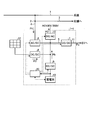
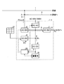
- FIG. 1 is a schematic configuration diagram of a quick charger for an electric vehicle according to the first embodiment.
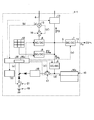
- FIG. 2 is a diagram showing details of the quick charger for an electric vehicle according to the first embodiment.
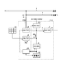
- FIG. 3 is an operation explanatory diagram when the facility storage battery is fully charged.
- FIG. 4 is an explanatory diagram of power storage for the facility storage battery.
- FIG. 5 is an explanatory diagram of power storage for a storage battery for facilities using input power from the solar power generation device.
- FIG. 6 is an explanatory diagram of reverse power transmission to the store side.
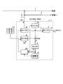
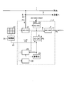
- FIG. 7 is a schematic configuration diagram of a quick charger for an electric vehicle according to the second embodiment.
- FIG. 1 is a schematic configuration diagram of a quick charger for an electric vehicle according to the first embodiment of the present invention
- FIG. 2 is a diagram showing details of the quick charger for an electric vehicle according to the first embodiment.
- the electric vehicle quick charger 1-1 shown in FIGS. 1 and 2 has a function of charging the electric vehicle EV.
- the electric vehicle EV includes not only one having no power source other than the electric motor but also a hybrid vehicle having a power source such as an internal combustion engine in addition to the electric motor.
- the quick charger 1-1 for an electric vehicle according to the present embodiment includes a bus 5, an AC / DC converter 6, a first DC / DC converter 7, a power controller 8, a second DC / DC converter 9,
- the storage battery 10 for facilities, the output line 11, the DC / AC converter 13, and the control apparatus 20 are comprised.
- the distribution board 2 is connected to a commercial power line 1, a store power line 3 and a charger power line 4.
- the electric vehicle quick charger 1-1 is connected to the commercial power line 1 and the store power line 3 through the charger power line 4 and the distribution board 2, respectively.
- the store power line 3 supplies power to a store such as a convenience store.
- the bus 5 is connected to the charger power line 4 via the AC / DC converter 6.
- the AC / DC converter 6 is included in a power receiving unit that receives power from an external power source, and functions as a commercial power receiving unit that receives power from a commercial power source.
- the AC / DC converter 6 converts the alternating current input from the power supply line 4 for the charger into a direct current and outputs it to the bus 5, and converts the direct current input from the bus 5 into an alternating current for the charger.
- the power can be output to the power line 4.
- the output line 11 is connected to the bus 5 via the first DC / DC converter 7.
- the output line 11 is a power supply line that supplies power to a battery mounted on the electric vehicle EV.
- the first DC / DC converter 7 supplies at least one of the received power P1 from the commercial power source, the input power P2 from the solar power generation device 12, or the discharge power Pb from the facility storage battery 10 to the electric vehicle EV.
- the first DC / DC converter 7 converts the direct current voltage of the bus 5 into a target voltage and outputs it to the output line 11.
- a solar power generation device 12 is connected to the bus 5 via a power controller 8.
- the solar power generation device 12 is a power generation device different from a commercial power source, and converts the light energy of sunlight into electrical energy and outputs a direct current.
- the maximum value of the generated power is 20 kW.
- the power controller 8 is included in a power receiving unit that receives power from an external power source, and functions as a power receiving unit power receiving unit that receives power from a power generator different from the commercial power source.
- the power controller 8 has a DC / DC converter and can execute MPPT (Maximum Power Point Tracking) control.
- the MPPT control is control for causing the solar power generation device 12 to generate power at a voltage and current value that can maximize the output.
- the current generated by the solar power generation device 12 is output to the bus 5 via the power controller 8.
- the power controller 8 increases the output voltage to the bus 5 higher than the voltage of the facility storage battery 10 in the control of the input power P ⁇ b> 2 input from the solar power generation device 12 to the bus 5.
- the power controller 8 controls the output voltage to the bus 5 to be equal to or lower than the voltage when the storage battery 10 for facilities is fully charged.
- a storage battery 10 for equipment is connected to the bus 5 via a second DC / DC converter 9.
- the second DC / DC converter 9 is a power converter connected to the facility storage battery 10.
- the storage battery 10 for facilities can be charged and discharged.
- the storage battery 10 for equipment of this embodiment is a lithium ion storage battery.
- the effective capacity (storage capacity) of the facility storage battery 10 is Qb (kWh).
- the effective capacity Qb is a capacity in a range used in the charge / discharge control among the total capacity of the facility storage battery 10. For example, when charge / discharge control is performed in the range of 10% to 90% of the total capacity of the storage battery 10 for facilities, the effective capacity Qb is a value of 80% of the total capacity. In this embodiment, since the facility storage battery 10 having a total capacity of 20 kWh is used in the range of 10 to 90% of the total capacity, the effective capacity Qb is 16 kWh.
- the second DC / DC converter 9 converts the voltage of the direct current of the bus 5 into a target voltage and outputs it to the facility storage battery 10, and the target voltage of the direct current discharged from the facility storage battery 10 Can be output to the bus 5. Even if the voltage of the storage battery 10 for facilities changes according to the electrical storage remaining amount SOC, the second DC / DC converter 9 can suppress fluctuations in the voltage output to the bus 5. Therefore, the stability of the voltage supplied to the electric vehicle EV can be improved. In addition, since the second DC / DC converter 9 is arranged, the number of batteries of the storage battery 10 for facilities (the number of series connection) can be changed without reassembling the circuit.
- a DC / AC converter 13 is connected to the bus 5.
- the DC / AC converter 13 can convert the direct current of the bus 5 into an alternating current of a target voltage and output it.
- the DC / AC converter 13 of the present embodiment can convert the direct current of the bus 5 and output alternating current 100V and alternating current 200V.
- the DC / AC converter 13 is used, for example, as an emergency power supply that outputs an alternating current during a power failure to a store that receives power supply from the store power line 3.
- the input / output device 22 shown in FIG. 2 is a device having a function as a notification means for notifying the user of the quick charger 1-1 for an electric vehicle and a function as an input means for receiving an input from the user. is there.
- the input / output device 22 of this embodiment notifies the user of information by displaying visual information such as characters and graphics on the display screen. Note that the input / output device 22 may notify information by sound or light instead of or in addition to characters or graphics.
- the input / output device 22 of this embodiment has a touch panel, and an input from a user is made by the touch panel.
- a voltmeter 15 and a switching device 16 are arranged on the power supply line 4 for the charger.
- the voltmeter 15 detects a voltage input from a commercial power source.
- the switching device 16 is disposed between the voltmeter 15 and the AC / DC converter 6.
- the switching device 16 is a relay that opens and closes the charger power line 4, and cuts off or connects the commercial power line 1 and the AC / DC converter 6.
- the voltmeter 15 changes the electrical signal output to the control device 20 and the switching device 16 when the voltage input from the commercial power line 1 is equal to or higher than a predetermined voltage and when it is lower than the predetermined voltage. Let The storage battery 10 for facilities has the monitoring apparatus 10a.
- the monitoring device 10 a monitors the temperature and voltage of the facility storage battery 10, the remaining power SOC (%), the current value to be charged / discharged, and the like, and outputs it to the control device 20.
- the facility storage battery 10 is connected to the control device 20 via a relay 17 and a switching power supply 18.
- the switching power supply 18 steps down the voltage of the facility storage battery 10 and outputs it to the control device 20.
- the control device 20 controls the quick charger 1-1 for the electric vehicle.
- the control device 20 of the present embodiment includes an AC / DC converter 6, a first DC / DC converter 7, a second DC / DC converter 9, a facility storage battery 10, a power controller 8, a DC / AC converter 13, a relay 17, and a relay. 21 and the input / output device 22, an AC / DC converter 6, a first DC / DC converter 7, a second DC / DC converter 9, a storage battery 10 for equipment, a power controller 8, a DC / AC converter 13, a relay 17. Control the relay 21 and the input / output device 22. Further, the control device 20 has a function of acquiring the power consumption of the electric load connected to the store power line 3 through communication or the like.
- the control device 20 When there is a charge request from the electric vehicle EV connected to the output line 11, the control device 20 sets the output power Po (kW) supplied to the electric vehicle EV.
- the maximum output power Pomax which is the maximum value of the output power Po, is 50 kW, but it may be any value.
- the control device 20 outputs to the first DC / DC converter 7 a voltage and current command value to be output to the output line 11 based on a request from the electric vehicle EV.
- the first DC / DC converter 7 controls the voltage and current output from the bus 5 to the output line 11 based on the command value from the control device 20.
- the electric vehicle quick charger 1-1 has at least one of received power P1 (kW) received from a commercial power source, input power P2 received from the solar power generation device 12, and discharge power Pb of the storage battery 10 for facilities. To supply output power Po to the electric vehicle EV.
- Control device 20 determines a command value for received power P1, a command value for input power P2, and a command value for discharge power Pb based on output power Po output to electric vehicle EV. Control device 20 outputs command values for voltage and current to be output to bus 5 based on the determined received power P1. The AC / DC converter 6 controls the voltage and current output to the bus 5 based on the command value received from the control device 20.
- the control device 20 acquires the input power P2 (voltage and current) generated by the solar power generation device 12 and input to the bus 5 from the power controller 8.
- the control device 20 can command the input power P2 to the power controller 8 to cause the solar power generation device 12 to generate power with an output different from the output determined by the MPPT control. For example, when the control device 20 instructs the power controller 8 to shut off the solar power generation device 12 and the bus 5 and sets the input power P2 to 0 or maximizes the output of the solar power generation device 12 It is possible to reduce the actual input power P ⁇ b> 2 with respect to the power (thinning the output of the solar power generation device 12).
- the control device 20 determines the discharge power Pb of the facility storage battery 10 and outputs a voltage and current command value output from the facility storage battery 10 to the bus 5 based on the discharge power Pb, or outputs from the bus 5 to the facility storage battery 10.
- the voltage and current command values are output to the second DC / DC converter 9.
- the second DC / DC converter 9 controls the voltage and current output from the facility storage battery 10 to the bus 5 or the voltage and current output from the bus 5 to the facility storage battery 10 based on the command value from the control device 20. To do.
- control device 20 determines the supply power P3 output from the bus 5 via the DC / AC converter 13, and determines the voltage and current command values output via the DC / AC converter 13 based on the supply power P3. Output to the DC / AC converter 13.
- the DC / AC converter 13 controls the voltage and current output via the DC / AC converter 13 based on the command value from the control device 20.
- the electric vehicle quick charger 1-1 is connected to a power receiving unit that receives power from an external power source and to the power receiving unit, and supplies power to the electric vehicle EV when the power is not received from the external power source.
- the storage battery 10 for facilities which can be provided.
- the external power source is a commercial power source and the solar power generation device 12.
- the electric vehicle quick charger 1-1 according to the present embodiment can charge the electric vehicle EV when it does not receive power from an external power source such as during a power failure.
- the electric vehicle quick charger 1-1 when the electric vehicle quick charger 1-1 receives no electric power from an external power source, the electric power for the control power source and the output electric power Po to be supplied to the electric vehicle EV are output from the storage battery 10 for facilities. can do. Therefore, the electric vehicle quick charger 1-1 functions independently when there is no external power supply, and can charge the electric vehicle EV.
- the control device 20 of the present embodiment can supply power for the control power source 20a from the commercial power source and the facility storage battery 10.
- the control device 20 can receive power from the commercial power source or the facility storage battery 10 to the control power source 20a, and can receive power from both the commercial power source and the facility storage battery 10 to the control power source 20a. It is.
- the commercial power supply fails when the electric vehicle quick charger 1-1 is functioning by receiving power from the commercial power supply to the control power supply 20a, the power supply to the control power supply 20a is stopped and the function is stopped.
- the system is restarted and functions by supplying power from the storage battery 10 for equipment to the control power source 20a.
- the control apparatus 20 may be comprised so that electric power can be further supplied with respect to the control power supply 20a from the solar power generation device 12.
- FIG. 1 the electric vehicle quick charger 1-1 is supplied with power from either the commercial power source or the solar power generation device 12 when functioning by receiving power from the external power source to the control power source 20a.
- the supply of power to the control power supply 20a is stopped, the function is stopped, and the function is restarted, and the power is supplied from the facility storage battery 10 to the control power supply 20a so as to function.
- a signal indicating a power failure output from the voltmeter 15 to the control device 20 is a control power OFF command for the control device 20.
- the control device 20 normally receives power from the commercial power source, the control device 20 operates by receiving power from the commercial power source to the control power source 20a.
- the power received via the charger power supply line 4 is stepped down to a voltage (for example, 12 V) for the control power supply 20a and supplied to the control device 20.
- the control device 20 stops the function of the electric vehicle quick charger 1-1 and stops supplying power to the control power supply 20a.
- the functions of the electric vehicle quick charger 1-1 include a charging function for the electric vehicle EV, an AC output to the outside via the DC / AC converter 13, a power generation control of the solar power generator 12 by the power controller 8, and a facility Charge / discharge of the storage battery 10 is included.
- the quick charger 1-1 for an electric vehicle according to the present embodiment temporarily stops its operation including the system power supply temporarily when the commercial power supply is interrupted.
- a signal indicating a power failure output from the voltmeter 15 to the switching device 16 is a disconnection command to the switching device 16.
- the switching device 16 connects the commercial power line 1 and the AC / DC converter 6 when normally receiving power from the commercial power source.
- the switching device 16 receives the disconnection command, the switching device 16 is opened, and the commercial power line 1 is cut off from the AC / DC converter 6.
- the opening / closing command for the switching device 16 may be issued by the control device 20.
- control power supply 20a After the control power supply OFF and disconnection are completed, the control power supply 20a is turned on again.
- the relay 21 is closed, and power is supplied from the battery 19 which is a power source for starting to the control power source 20a of the control device 20.
- the control device 20 instructs the relay 21 to turn on the activation power after a predetermined time.
- the relay 21 is closed after the quick charger 1-1 for the electric vehicle stops functioning, and the control power supply 20a is turned on again.
- the control device 20 When power is supplied from the battery 19, the control device 20 communicates with the monitoring device 10 a to check the state of the facility storage battery 10. If the facility storage battery 10 is normal, the control device 20 issues a power supply command to the facility storage battery 10 and closes the relay 17 (d ′). When the relay 17 is closed, power is supplied from the facility storage battery 10 to the control power supply 20a of the control device 20 via the switching power supply 18, and the electric vehicle quick charger 1-1 functions.
- the control device 20 When the electric vehicle quick charger 1-1 functions by the power from the facility storage battery 10 at the time of a power failure of the commercial power supply, the control device 20 outputs the output power Po for the electric vehicle EV more than when the power is supplied from the commercial power supply.
- the maximum output power Pomax that is the maximum value of is reduced.
- the control device 20 changes the maximum value of the current supplied to the electric vehicle EV.
- the maximum current value for the electric vehicle EV at the time of a power failure when the commercial power source is interrupted is smaller than the maximum current value for the electric vehicle EV in a normal time when power is supplied from the commercial power source.
- the maximum output power Pomax during normal times is 50 kW
- the maximum output power Pomax during a power failure is 25 kW.
- the control device 20 When charging the electric vehicle EV at the time of a power failure, the control device 20 outputs the amount of the input power P2 from the solar power generation device 12 that is insufficient with respect to the output power Po by the facility storage battery 10. That is, at the time of a power failure, the discharge power Pb of the facility storage battery 10 is determined by the following formula (1).
- Pb Po ⁇ P2 (1)
- the control device 20 charges the facility storage battery 10 with the input power P2.
- the control apparatus 20 charges the storage battery 10 for facilities with the input electric power P2, when not charging with respect to the electric vehicle EV.
- the control device 20 may determine the discharge power Pb by the following equation (2) when there is power supply to the outside via the DC / AC converter 13 at the time of a power failure.
- Pb Po-P2-P3 (2)
- the quick charger 1-1 for the electric vehicle limits the number of users who can charge the electric vehicle EV when power cannot be received from the commercial power source, compared to the case where power can be received from the commercial power source. To do.
- the electric vehicle quick charger 1-1 performs user authentication based on information input to the input / output device 22, for example, a password.
- the input / output device 22 and the control device 20 function as authentication means for performing user authentication.
- a user (vehicle) who can use the charging function of the quick charger 1-1 for an electric vehicle than a normal time that can receive power from the commercial power source is used by the control device 20. Limited by.
- the control device 20 permits a user of a public vehicle such as an ambulance or a police car or an emergency vehicle to be charged by the quick charger 1-1 for an electric vehicle, and the vehicle other than the public vehicle or the emergency vehicle The user can be prevented from being charged by the electric vehicle quick charger 1-1.
- the electric vehicle quick charger 1-1 may restrict users who can charge the electric vehicle EV by requesting the input of a password only during a power failure.
- the user authentication method is not limited to a password, and may be, for example, a key, an ID card, biometric authentication, or the like.
- the electric vehicle quick charger 1-1 may include an authentication unit separately from the control device 20.
- the control device 20 may acquire information related to use authentication from the authentication unit, and use restriction may be performed at the time of a power failure or the like based on the information.
- the authentication unit itself may restrict use at the time of a power failure or the like. You may do it.
- the power source of the control power supply 20a becomes the facility storage battery. 10 to a commercial power source. Since the switching device 16 is opened at the time of a power failure of the commercial power source, the power source of the control power source 20a can be switched from the facility storage battery 10 to the commercial power source in a predetermined procedure when the commercial power source is restored.
- the control device 20 stops the power supply to the control power source 20a by the facility storage battery 10 after the commercial power source is restored, and then connects the commercial power source to the AC / DC converter 6 by the switching device 16 to quickly charge the electric vehicle 1- 1 is restarted.
- FIG. 3 is an operation explanatory diagram when the facility storage battery 10 is fully charged.
- the quick charger 1-1 for an electric vehicle according to the present embodiment has a solar battery when the storage battery 10 for facilities is fully charged (for example, the remaining amount of stored SOC is 100%) and the electric vehicle EV is not charged.
- Input power P ⁇ b> 2 from the photovoltaic device 12 is supplied to the store power line 3.
- the electric vehicle quick charger 1-1 controls the input power P2 so as not to generate a reverse power flow to the commercial power line 1.
- the control device 20 controls the input power P2 from the solar power generation device 12 with the constant power consumption in the store as an upper limit.
- the control device 20 may use the actual power consumption in the store as the upper limit of the input power P2 from the solar power generation device 12 instead of the steady power consumption.
- the electric vehicle quick charger 1-1 calculates the discharge power Pb of the facility storage battery 10 by the following equation (3).
- Pb Po-P1-P2 (3)
- a maximum received power P1max is determined as an upper limit based on the contract power and the power consumption of the store.
- the maximum received power P1max is the difference between the contract power and the power consumption of the store. Even if the received power P1 is set to the maximum received power P1max, when the sum of the received power P1 and the input power P2 is insufficient with respect to the output power Po, the discharge power Pb of the storage battery 10 for facilities corresponds. Thereby, the amount of power received from the commercial power source can be suppressed.
- the electric vehicle quick charger 1-1 stores electricity in the facility storage battery 10 when surplus power is generated when the electric vehicle EV is charged.
- FIG. 4 is an explanatory diagram of power storage for the facility storage battery 10.
- the electric vehicle EV When the electric vehicle EV is charged, for example, when the electric vehicle EV is charged, the sum of the maximum received power P1max and the input power P2 from the solar power generation device 12 is larger than the output power Po, that is, When the following formula (4) is satisfied, the battery is stored in the facility storage battery 10. Po ⁇ P1max + P2 (4)
- the stored power Pbin is calculated by the following equation (5).
- the facility storage battery 10 has an allowable maximum stored power Pinmax, which is the maximum power allowed for power storage.
- the received power P1 is adjusted so that the stored power Pbin is equal to or less than the allowable maximum stored power Pinmax.
- the electric vehicle quick charger 1-1 stores the facility storage battery 10 when the output power Po is less than the input power P2 from the solar power generation device 12.
- FIG. 5 is an explanatory diagram of power storage for the facility storage battery 10 by the input power P ⁇ b> 2 from the solar power generation device 12.
- the control device 20 charges the facility storage battery 10 with the input power P2.
- the stored power Pbin is calculated by the following formula (6).
- Pbin P2-Po (6)
- surplus power is generated even when the stored power Pbin is set to the allowable maximum stored power Pinmax when charging the electric vehicle EV, the surplus power is output to the store power line 3.
- Output power (reverse transmission power) P1out from the AC / DC converter 6 to the store side is calculated by the following equation (7).
- P1out P2- (Po + Pinmax) (7)
- the input power P2 from the solar power generation device 12 is limited so that the reverse transmission power P1out does not exceed the power consumption in the store.
- the electric vehicle quick charger 1-1 performs reverse power transmission to the store power line 3 when the power consumption of the store exceeds the contract power.
- FIG. 6 is an explanatory diagram of reverse power transmission to the store side.
- the control device 20 outputs power from the storage battery 10 for equipment so that the following formula (8) is established.
- P1out + Po P2 + Pb (8)
- the reverse transmission power P1out is a difference between the power consumption of the store and the contract power.
- the reverse transmission power P1out is limited if the reverse transmission power P1out is not sufficient for the difference between the power consumption of the store and the contract power even if the discharge power Pb of the facility storage battery 10 is the maximum allowable value Pbmax.
- the quick charger 1-1 for the electric vehicle uses 0 as the received power P1 from the commercial power source. It can be.
- the control device 20 predicts that the charge amount for the electric vehicle EV can be secured based on the remaining amount of storage SOC of the facility storage battery 10 and the input power P2 from the solar power generation device 12, the electric vehicle EV is Judge that charging is possible.
- the control device 20 determines a charging pattern of predetermined output ⁇ predetermined charging time based on a charging request from the electric vehicle EV, and can complete charging according to the charging pattern with the input power P2 and the discharging power Pb. When predicted, the received power P1 is set to zero.
- an undervoltage relay or the like may be provided instead of the voltmeter 15.
- the undervoltage relay when the voltage from the commercial power supply line 1 is less than a predetermined voltage for a predetermined time or longer, signals output to the control device 20 and the switching device 16 indicate normal power reception. The signal changes to a signal indicating a power outage.
- the facility storage battery 10 is connected to the bus 5 via the second DC / DC converter 9, but the facility storage battery 10 is a power converter such as the second DC / DC converter 9. It may be connected to the bus 5 without being interposed.
- the power controller 8 as a power receiving means for power generators received power from the solar power generator 12, it may replace with this and may receive power from a wind power generator.
- the electric vehicle quick charger 1-1 has the power controller 8.
- the power controller 8 may be provided outside the electric vehicle quick charger 1-1. .
- the controller includes an electric vehicle quick charger 1-1, an output power Po for the electric vehicle EV, a discharge power Pb (voltage and current) of the storage battery 10 for the facility, and an input power P2 (voltage and current) from the solar power generator 12.
- the controller communicates with the power controller 8 the conversion power command (voltage, current, power upper limit command) of the power controller 8, the power command (voltage, current, power upper limit command) of the AC / DC converter 6 and the like. Output.
- the power receiving means is either a commercial power receiving means for receiving power from a commercial power source or a power receiving apparatus power receiving means for receiving power from a power generator different from the commercial power source. You may make it have.
- the electric vehicle quick charger 1-1 has, for example, commercial power receiving means, and the power receiving device power receiving means for receiving power from the solar power generation device 12 or the like may be omitted. Even if the configuration does not include the power receiving means for the power generator, the quick charger 1-1 for the electric vehicle having the facility storage battery 10 supplies power to the electric vehicle from the facility storage battery 10 when it does not receive power from the commercial power source. Can be supplied.
- the electric vehicle quick charger 1-1 may include a power receiving device power receiving means, and the commercial power receiving means may be omitted.
- the power receiving means for a power generation device may receive power from a plurality of different types of power generation devices.
- the power receiving means for the power generator may receive power from both the solar power generator 12 and the wind power generator.
- FIG. 7 is a schematic configuration diagram of a quick charger for an electric vehicle according to the second embodiment.
- the quick charger 1-2 for the electric vehicle according to the present embodiment differs from the quick charger 1-1 for the electric vehicle according to the first embodiment in that the solar power generation device 12 is not connected to the power converter. It is a point connected to the storage battery 10 for facilities.
- connection line 23 of the solar power generation device 12 is connected to a line connecting the facility storage battery 10 and the second DC / DC converter 9.
- a connection box 24 is disposed on the connection line 23.
- the connection box 24 includes a contactor and a controller, and cuts off or connects the solar power generation device 12 and the electric vehicle quick charger 1-2.
- the junction box 24 does not have a power converter.
- the connection box 24 shuts off the solar power generation device 12 and the rapid charger 1-2 for the electric vehicle when an overcurrent flows through the connection line 23 or when the voltage of the storage battery 10 for facilities is too high.
- the connection box 24 when the voltage of the connection line 23 is the voltage of the storage battery 10 for facilities when the remaining power SOC is 100%, the solar power generator 12 and the quick charger 1-2 for the electric vehicle And disconnect.
- the power controller 8 since the power controller 8 is not provided, the power controller 8 cannot narrow down the output of the solar power generation device 12. However, when the input power P2 from the solar power generation device 12 is unnecessary, the solar power generation device 12 is disconnected by the connection box 24 if the storage battery 10 for facilities is fully charged. Therefore, the electric vehicle quick charger 1-2 can exhibit the same function as the electric vehicle quick charger 1-1 of the first embodiment.
Landscapes
- Engineering & Computer Science (AREA)
- Power Engineering (AREA)
- Transportation (AREA)
- Mechanical Engineering (AREA)
- Charge And Discharge Circuits For Batteries Or The Like (AREA)
Abstract
La présente invention se rapporte à un chargeur rapide (1-1) pour un véhicule électrique, ledit chargeur rapide comprenant : un moyen de réception d'énergie (6) qui reçoit l'énergie d'une alimentation électrique externe ; et une batterie rechargeable (10) qui est raccordée au moyen de réception d'énergie et qui peut fournir l'énergie à un véhicule électrique (EV) lorsque l'énergie n'est pas reçue de l'alimentation électrique externe. Lorsque l'énergie n'est pas reçue de l'alimentation électrique externe, l'énergie pour une alimentation électrique de commande (20a) d'un dispositif de commande (20) et l'énergie de sortie (Po) qui doit être fournie au véhicule électrique sont, de préférence, transmises depuis la batterie rechargeable. Le chargeur rapide peut comprendre une pluralité de moyens de réception d'énergie qui comprennent un moyen de réception d'énergie commerciale qui reçoit l'énergie d'une alimentation électrique commerciale.
Priority Applications (1)
| Application Number | Priority Date | Filing Date | Title |
|---|---|---|---|
| PCT/JP2012/078248 WO2014068733A1 (fr) | 2012-10-31 | 2012-10-31 | Chargeur rapide pour un véhicule électrique |
Applications Claiming Priority (1)
| Application Number | Priority Date | Filing Date | Title |
|---|---|---|---|
| PCT/JP2012/078248 WO2014068733A1 (fr) | 2012-10-31 | 2012-10-31 | Chargeur rapide pour un véhicule électrique |
Publications (1)
| Publication Number | Publication Date |
|---|---|
| WO2014068733A1 true WO2014068733A1 (fr) | 2014-05-08 |
Family
ID=50626699
Family Applications (1)
| Application Number | Title | Priority Date | Filing Date |
|---|---|---|---|
| PCT/JP2012/078248 Ceased WO2014068733A1 (fr) | 2012-10-31 | 2012-10-31 | Chargeur rapide pour un véhicule électrique |
Country Status (1)
| Country | Link |
|---|---|
| WO (1) | WO2014068733A1 (fr) |
Cited By (5)
| Publication number | Priority date | Publication date | Assignee | Title |
|---|---|---|---|---|
| EP3600947A4 (fr) * | 2017-03-24 | 2020-09-09 | The Noco Company | Station et système de recharge rapide de véhicule électrique (ev) |
| LU102237B1 (de) * | 2020-11-25 | 2022-05-30 | Phoenix Contact Gmbh & Co | Verfahren zum Ermitteln der Verdrahtung und Funktion von Leistungswandlern einer Ladesäule zum Laden von Elektrofahrzeugen |
| US11600996B2 (en) | 2017-03-24 | 2023-03-07 | The Noco Company | Electric vehicle (EV) fast recharge station and system |
| EP4195450A4 (fr) * | 2020-09-30 | 2023-10-04 | Huawei Digital Power Technologies Co., Ltd. | Bloc de charge et système de charge |
| US12528378B2 (en) | 2024-05-15 | 2026-01-20 | Contemporary Amperex Technology (Hong Kong) Limited | Charging method and charging apparatus |
Citations (3)
| Publication number | Priority date | Publication date | Assignee | Title |
|---|---|---|---|---|
| JPH06178461A (ja) * | 1992-12-09 | 1994-06-24 | Japan Storage Battery Co Ltd | 系統連系電源システム |
| JP2011200104A (ja) * | 2010-01-08 | 2011-10-06 | Jfe Engineering Corp | 急速充電装置 |
| JP2012050291A (ja) * | 2010-08-30 | 2012-03-08 | Terrara Code Research Institute Inc | 給電スタンド |
-
2012
- 2012-10-31 WO PCT/JP2012/078248 patent/WO2014068733A1/fr not_active Ceased
Patent Citations (3)
| Publication number | Priority date | Publication date | Assignee | Title |
|---|---|---|---|---|
| JPH06178461A (ja) * | 1992-12-09 | 1994-06-24 | Japan Storage Battery Co Ltd | 系統連系電源システム |
| JP2011200104A (ja) * | 2010-01-08 | 2011-10-06 | Jfe Engineering Corp | 急速充電装置 |
| JP2012050291A (ja) * | 2010-08-30 | 2012-03-08 | Terrara Code Research Institute Inc | 給電スタンド |
Cited By (10)
| Publication number | Priority date | Publication date | Assignee | Title |
|---|---|---|---|---|
| EP3600947A4 (fr) * | 2017-03-24 | 2020-09-09 | The Noco Company | Station et système de recharge rapide de véhicule électrique (ev) |
| AU2021203245B2 (en) * | 2017-03-24 | 2021-07-01 | The Noco Company | Electric vehicle (EV) fast recharge station and system |
| US11600996B2 (en) | 2017-03-24 | 2023-03-07 | The Noco Company | Electric vehicle (EV) fast recharge station and system |
| US11949274B2 (en) | 2017-03-24 | 2024-04-02 | The Noco Company | Electric vehicle (EV) fast recharge station and system |
| US12328018B2 (en) | 2017-03-24 | 2025-06-10 | The Noco Company | Electric vehicle (EV) fast charge station and system |
| US12512691B2 (en) | 2017-03-24 | 2025-12-30 | The Noco Company | Electric vehicle (EV) fast recharge station and system |
| EP4195450A4 (fr) * | 2020-09-30 | 2023-10-04 | Huawei Digital Power Technologies Co., Ltd. | Bloc de charge et système de charge |
| US12194875B2 (en) * | 2020-09-30 | 2025-01-14 | Huawei Digital Power Technologies Co., Ltd. | Charging module and charging system |
| LU102237B1 (de) * | 2020-11-25 | 2022-05-30 | Phoenix Contact Gmbh & Co | Verfahren zum Ermitteln der Verdrahtung und Funktion von Leistungswandlern einer Ladesäule zum Laden von Elektrofahrzeugen |
| US12528378B2 (en) | 2024-05-15 | 2026-01-20 | Contemporary Amperex Technology (Hong Kong) Limited | Charging method and charging apparatus |
Similar Documents
| Publication | Publication Date | Title |
|---|---|---|
| AU2021201000B2 (en) | Renewable energy system with integrated home power supply system | |
| US9566867B2 (en) | Vehicle-solar-grid integration | |
| JP5709779B2 (ja) | 電力貯蔵型の発電システム | |
| US9899871B2 (en) | Islanded operating system | |
| KR101793579B1 (ko) | 직류-교류 공통 모선형 하이브리드 전원 시스템 | |
| JP2014212659A (ja) | 電力供給システム及びその方法 | |
| KR20190085089A (ko) | 부하 시험 시스템 | |
| WO2015103164A1 (fr) | Système de charge rapide courant continu-courant continu à base de batterie de station de charge de véhicule électrique | |
| US20130175860A1 (en) | Battery power supply device and method of controlling power of the same | |
| CN105379049A (zh) | 电力控制器、电力控制方法以及电力控制系统 | |
| WO2014068733A1 (fr) | Chargeur rapide pour un véhicule électrique | |
| US20170063254A1 (en) | Inverter system | |
| Song et al. | Design and integration of the bi-directional electric vehicle charger into the microgrid as emergency power supply | |
| US10320327B1 (en) | Power storage power conditioner | |
| JP2014027856A (ja) | 系統連系装置 | |
| JP2025131711A (ja) | 充放電システム、充放電システムの制御方法、およびコンピュータプログラム | |
| JP7282024B2 (ja) | 発電機車及び発電機車システム | |
| WO2014068732A1 (fr) | Chargeur rapide | |
| US11791638B2 (en) | Power supply system | |
| EP4142083A1 (fr) | Système d'alimentation électrique | |
| EP4142090A1 (fr) | Système d'alimentation électrique et procédé de gestion d'énergie | |
| WO2014068735A1 (fr) | Chargeur rapide | |
| JP2023095009A (ja) | 電力システム及びその運転方法 | |
| JP2018019575A (ja) | 電力供給システム、及び電力変換装置 | |
| US20250379445A1 (en) | Dark start support verification |
Legal Events
| Date | Code | Title | Description |
|---|---|---|---|
| 121 | Ep: the epo has been informed by wipo that ep was designated in this application |
Ref document number: 12887728 Country of ref document: EP Kind code of ref document: A1 |
|
| NENP | Non-entry into the national phase |
Ref country code: DE |
|
| 122 | Ep: pct application non-entry in european phase |
Ref document number: 12887728 Country of ref document: EP Kind code of ref document: A1 |
|
| NENP | Non-entry into the national phase |
Ref country code: JP |