WO2014068778A1 - 成膜装置 - Google Patents
成膜装置 Download PDFInfo
- Publication number
- WO2014068778A1 WO2014068778A1 PCT/JP2012/078580 JP2012078580W WO2014068778A1 WO 2014068778 A1 WO2014068778 A1 WO 2014068778A1 JP 2012078580 W JP2012078580 W JP 2012078580W WO 2014068778 A1 WO2014068778 A1 WO 2014068778A1
- Authority
- WO
- WIPO (PCT)
- Prior art keywords
- chamber
- solution
- forming apparatus
- spray
- port
- Prior art date
- Legal status (The legal status is an assumption and is not a legal conclusion. Google has not performed a legal analysis and makes no representation as to the accuracy of the status listed.)
- Ceased
Links
Images


Classifications
-
- B—PERFORMING OPERATIONS; TRANSPORTING
- B05—SPRAYING OR ATOMISING IN GENERAL; APPLYING FLUENT MATERIALS TO SURFACES, IN GENERAL
- B05B—SPRAYING APPARATUS; ATOMISING APPARATUS; NOZZLES
- B05B7/00—Spraying apparatus for discharge of liquids or other fluent materials from two or more sources, e.g. of liquid and air, of powder and gas
- B05B7/0012—Apparatus for achieving spraying before discharge from the apparatus
-
- C—CHEMISTRY; METALLURGY
- C23—COATING METALLIC MATERIAL; COATING MATERIAL WITH METALLIC MATERIAL; CHEMICAL SURFACE TREATMENT; DIFFUSION TREATMENT OF METALLIC MATERIAL; COATING BY VACUUM EVAPORATION, BY SPUTTERING, BY ION IMPLANTATION OR BY CHEMICAL VAPOUR DEPOSITION, IN GENERAL; INHIBITING CORROSION OF METALLIC MATERIAL OR INCRUSTATION IN GENERAL
- C23C—COATING METALLIC MATERIAL; COATING MATERIAL WITH METALLIC MATERIAL; SURFACE TREATMENT OF METALLIC MATERIAL BY DIFFUSION INTO THE SURFACE, BY CHEMICAL CONVERSION OR SUBSTITUTION; COATING BY VACUUM EVAPORATION, BY SPUTTERING, BY ION IMPLANTATION OR BY CHEMICAL VAPOUR DEPOSITION, IN GENERAL
- C23C16/00—Chemical coating by decomposition of gaseous compounds, without leaving reaction products of surface material in the coating, i.e. chemical vapour deposition [CVD] processes
- C23C16/44—Chemical coating by decomposition of gaseous compounds, without leaving reaction products of surface material in the coating, i.e. chemical vapour deposition [CVD] processes characterised by the method of coating
- C23C16/455—Chemical coating by decomposition of gaseous compounds, without leaving reaction products of surface material in the coating, i.e. chemical vapour deposition [CVD] processes characterised by the method of coating characterised by the method used for introducing gases into reaction chamber or for modifying gas flows in reaction chamber
-
- B—PERFORMING OPERATIONS; TRANSPORTING
- B05—SPRAYING OR ATOMISING IN GENERAL; APPLYING FLUENT MATERIALS TO SURFACES, IN GENERAL
- B05B—SPRAYING APPARATUS; ATOMISING APPARATUS; NOZZLES
- B05B12/00—Arrangements for controlling delivery; Arrangements for controlling the spray area
- B05B12/16—Arrangements for controlling delivery; Arrangements for controlling the spray area for controlling the spray area
- B05B12/18—Arrangements for controlling delivery; Arrangements for controlling the spray area for controlling the spray area using fluids, e.g. gas streams
-
- B—PERFORMING OPERATIONS; TRANSPORTING
- B05—SPRAYING OR ATOMISING IN GENERAL; APPLYING FLUENT MATERIALS TO SURFACES, IN GENERAL
- B05B—SPRAYING APPARATUS; ATOMISING APPARATUS; NOZZLES
- B05B14/00—Arrangements for collecting, re-using or eliminating excess spraying material
-
- B—PERFORMING OPERATIONS; TRANSPORTING
- B05—SPRAYING OR ATOMISING IN GENERAL; APPLYING FLUENT MATERIALS TO SURFACES, IN GENERAL
- B05B—SPRAYING APPARATUS; ATOMISING APPARATUS; NOZZLES
- B05B15/00—Details of spraying plant or spraying apparatus not otherwise provided for; Accessories
- B05B15/50—Arrangements for cleaning; Arrangements for preventing deposits, drying-out or blockage; Arrangements for detecting improper discharge caused by the presence of foreign matter
- B05B15/55—Arrangements for cleaning; Arrangements for preventing deposits, drying-out or blockage; Arrangements for detecting improper discharge caused by the presence of foreign matter using cleaning fluids
-
- B—PERFORMING OPERATIONS; TRANSPORTING
- B05—SPRAYING OR ATOMISING IN GENERAL; APPLYING FLUENT MATERIALS TO SURFACES, IN GENERAL
- B05B—SPRAYING APPARATUS; ATOMISING APPARATUS; NOZZLES
- B05B7/00—Spraying apparatus for discharge of liquids or other fluent materials from two or more sources, e.g. of liquid and air, of powder and gas
- B05B7/02—Spray pistols; Apparatus for discharge
- B05B7/04—Spray pistols; Apparatus for discharge with arrangements for mixing liquids or other fluent materials before discharge
- B05B7/0416—Spray pistols; Apparatus for discharge with arrangements for mixing liquids or other fluent materials before discharge with arrangements for mixing one gas and one liquid
- B05B7/0483—Spray pistols; Apparatus for discharge with arrangements for mixing liquids or other fluent materials before discharge with arrangements for mixing one gas and one liquid with gas and liquid jets intersecting in the mixing chamber
-
- C—CHEMISTRY; METALLURGY
- C23—COATING METALLIC MATERIAL; COATING MATERIAL WITH METALLIC MATERIAL; CHEMICAL SURFACE TREATMENT; DIFFUSION TREATMENT OF METALLIC MATERIAL; COATING BY VACUUM EVAPORATION, BY SPUTTERING, BY ION IMPLANTATION OR BY CHEMICAL VAPOUR DEPOSITION, IN GENERAL; INHIBITING CORROSION OF METALLIC MATERIAL OR INCRUSTATION IN GENERAL
- C23C—COATING METALLIC MATERIAL; COATING MATERIAL WITH METALLIC MATERIAL; SURFACE TREATMENT OF METALLIC MATERIAL BY DIFFUSION INTO THE SURFACE, BY CHEMICAL CONVERSION OR SUBSTITUTION; COATING BY VACUUM EVAPORATION, BY SPUTTERING, BY ION IMPLANTATION OR BY CHEMICAL VAPOUR DEPOSITION, IN GENERAL
- C23C16/00—Chemical coating by decomposition of gaseous compounds, without leaving reaction products of surface material in the coating, i.e. chemical vapour deposition [CVD] processes
- C23C16/44—Chemical coating by decomposition of gaseous compounds, without leaving reaction products of surface material in the coating, i.e. chemical vapour deposition [CVD] processes characterised by the method of coating
- C23C16/4412—Details relating to the exhausts, e.g. pumps, filters, scrubbers, particle traps
-
- C—CHEMISTRY; METALLURGY
- C23—COATING METALLIC MATERIAL; COATING MATERIAL WITH METALLIC MATERIAL; CHEMICAL SURFACE TREATMENT; DIFFUSION TREATMENT OF METALLIC MATERIAL; COATING BY VACUUM EVAPORATION, BY SPUTTERING, BY ION IMPLANTATION OR BY CHEMICAL VAPOUR DEPOSITION, IN GENERAL; INHIBITING CORROSION OF METALLIC MATERIAL OR INCRUSTATION IN GENERAL
- C23C—COATING METALLIC MATERIAL; COATING MATERIAL WITH METALLIC MATERIAL; SURFACE TREATMENT OF METALLIC MATERIAL BY DIFFUSION INTO THE SURFACE, BY CHEMICAL CONVERSION OR SUBSTITUTION; COATING BY VACUUM EVAPORATION, BY SPUTTERING, BY ION IMPLANTATION OR BY CHEMICAL VAPOUR DEPOSITION, IN GENERAL
- C23C16/00—Chemical coating by decomposition of gaseous compounds, without leaving reaction products of surface material in the coating, i.e. chemical vapour deposition [CVD] processes
- C23C16/44—Chemical coating by decomposition of gaseous compounds, without leaving reaction products of surface material in the coating, i.e. chemical vapour deposition [CVD] processes characterised by the method of coating
- C23C16/448—Chemical coating by decomposition of gaseous compounds, without leaving reaction products of surface material in the coating, i.e. chemical vapour deposition [CVD] processes characterised by the method of coating characterised by the method used for generating reactive gas streams, e.g. by evaporation or sublimation of precursor materials
- C23C16/4486—Chemical coating by decomposition of gaseous compounds, without leaving reaction products of surface material in the coating, i.e. chemical vapour deposition [CVD] processes characterised by the method of coating characterised by the method used for generating reactive gas streams, e.g. by evaporation or sublimation of precursor materials by producing an aerosol and subsequent evaporation of the droplets or particles
-
- C—CHEMISTRY; METALLURGY
- C23—COATING METALLIC MATERIAL; COATING MATERIAL WITH METALLIC MATERIAL; CHEMICAL SURFACE TREATMENT; DIFFUSION TREATMENT OF METALLIC MATERIAL; COATING BY VACUUM EVAPORATION, BY SPUTTERING, BY ION IMPLANTATION OR BY CHEMICAL VAPOUR DEPOSITION, IN GENERAL; INHIBITING CORROSION OF METALLIC MATERIAL OR INCRUSTATION IN GENERAL
- C23C—COATING METALLIC MATERIAL; COATING MATERIAL WITH METALLIC MATERIAL; SURFACE TREATMENT OF METALLIC MATERIAL BY DIFFUSION INTO THE SURFACE, BY CHEMICAL CONVERSION OR SUBSTITUTION; COATING BY VACUUM EVAPORATION, BY SPUTTERING, BY ION IMPLANTATION OR BY CHEMICAL VAPOUR DEPOSITION, IN GENERAL
- C23C16/00—Chemical coating by decomposition of gaseous compounds, without leaving reaction products of surface material in the coating, i.e. chemical vapour deposition [CVD] processes
- C23C16/44—Chemical coating by decomposition of gaseous compounds, without leaving reaction products of surface material in the coating, i.e. chemical vapour deposition [CVD] processes characterised by the method of coating
- C23C16/46—Chemical coating by decomposition of gaseous compounds, without leaving reaction products of surface material in the coating, i.e. chemical vapour deposition [CVD] processes characterised by the method of coating characterised by the method used for heating the substrate
-
- B—PERFORMING OPERATIONS; TRANSPORTING
- B05—SPRAYING OR ATOMISING IN GENERAL; APPLYING FLUENT MATERIALS TO SURFACES, IN GENERAL
- B05B—SPRAYING APPARATUS; ATOMISING APPARATUS; NOZZLES
- B05B1/00—Nozzles, spray heads or other outlets, with or without auxiliary devices such as valves, heating means
- B05B1/02—Nozzles, spray heads or other outlets, with or without auxiliary devices such as valves, heating means designed to produce a jet, spray, or other discharge of particular shape or nature, e.g. in single drops, or having an outlet of particular shape
- B05B1/04—Nozzles, spray heads or other outlets, with or without auxiliary devices such as valves, heating means designed to produce a jet, spray, or other discharge of particular shape or nature, e.g. in single drops, or having an outlet of particular shape in flat form, e.g. fan-like, sheet-like
- B05B1/044—Slits, e.g. narrow openings defined by two straight and parallel lips; Elongated outlets for producing very wide discharges, e.g. fluid curtains
-
- B—PERFORMING OPERATIONS; TRANSPORTING
- B05—SPRAYING OR ATOMISING IN GENERAL; APPLYING FLUENT MATERIALS TO SURFACES, IN GENERAL
- B05B—SPRAYING APPARATUS; ATOMISING APPARATUS; NOZZLES
- B05B7/00—Spraying apparatus for discharge of liquids or other fluent materials from two or more sources, e.g. of liquid and air, of powder and gas
- B05B7/0075—Nozzle arrangements in gas streams
-
- B—PERFORMING OPERATIONS; TRANSPORTING
- B05—SPRAYING OR ATOMISING IN GENERAL; APPLYING FLUENT MATERIALS TO SURFACES, IN GENERAL
- B05B—SPRAYING APPARATUS; ATOMISING APPARATUS; NOZZLES
- B05B7/00—Spraying apparatus for discharge of liquids or other fluent materials from two or more sources, e.g. of liquid and air, of powder and gas
- B05B7/02—Spray pistols; Apparatus for discharge
- B05B7/08—Spray pistols; Apparatus for discharge with separate outlet orifices, e.g. to form parallel jets, i.e. the axis of the jets being parallel, to form intersecting jets, i.e. the axis of the jets converging but not necessarily intersecting at a point
- B05B7/0807—Spray pistols; Apparatus for discharge with separate outlet orifices, e.g. to form parallel jets, i.e. the axis of the jets being parallel, to form intersecting jets, i.e. the axis of the jets converging but not necessarily intersecting at a point to form intersecting jets
- B05B7/0861—Spray pistols; Apparatus for discharge with separate outlet orifices, e.g. to form parallel jets, i.e. the axis of the jets being parallel, to form intersecting jets, i.e. the axis of the jets converging but not necessarily intersecting at a point to form intersecting jets with one single jet constituted by a liquid or a mixture containing a liquid and several gas jets
Definitions
- the present invention relates to a film forming apparatus for forming a film on a substrate.
- spray method and “mist method” exist as methods for forming a film on a substrate.
- spray method droplets of about 10 ⁇ m to 100 ⁇ m are ejected onto the substrate.
- mist method a mist of about several ⁇ m is sprayed on the substrate.
- the solution is made into a fine mist of about several ⁇ m by an ultrasonic vibrator or the like, and the mist solution is passed through a long pipe to the reaction chamber (or spray port) in which the substrate is placed. ).
- Patent Document 1 exists as a prior document relating to the “spray method”. Further, for example, Patent Document 2 exists as a prior document relating to the “mist method”.
- the gas that collides with the solution usually requires a large pressure and flow rate. For this reason, the initial velocity of the droplet increases, and the droplet still collides with the substrate being heated. Since the diameter of the droplet is as large as about 100 ⁇ m to several tens of ⁇ m, it cannot receive the thermal energy necessary for the chemical reaction. Therefore, the “spray method” has a problem that the film quality of the film formed on the substrate deteriorates.
- the mist solution transported by the carrier gas is supplied to the heated substrate. For this reason, since the initial velocity of the mist is small and the solvent evaporates in the vicinity of the substrate surface, the film quality of the film formed on the substrate is improved in the “mist method”.
- the “mist method” requires a large mechanism for misting the solution. Therefore, the film forming apparatus to which the “mist method” is applied has a problem of increasing the size of the entire apparatus.
- the misted solution in a film forming apparatus to which the “mist method” is applied, it is necessary to transport the misted solution to a reaction chamber (or spraying port) where a substrate is placed via a long pipe. Therefore, the misted solution easily aggregates in the pipe. Therefore, the “mist method” has a problem that it is difficult to efficiently use a material (solution) for film formation.
- mist having a non-uniform concentration is conveyed to the substrate due to aggregation of the solution in the pipe. Therefore, it is necessary to provide a mechanism for rectifying the mist in the mist supply section near the substrate. Therefore, in the film forming apparatus to which the “mist method” is applied, there are problems that the mist supply unit is increased in size and weight and is difficult to maintain.
- the present invention provides a film forming apparatus that can form a film with good film quality on a substrate, can effectively use the solution for the film forming process, and can reduce the size of the entire apparatus.
- the purpose is to provide.
- a film forming apparatus is a film forming apparatus for forming a film on a substrate, the spray nozzle for injecting a droplet solution, and the spray nozzle
- a first chamber capable of containing the dropletized solution jetted from, a first gas supply port for jetting a gas that collides against the solution existing in the first chamber, The second chamber adjacent to the first chamber, and a wall surface existing between the first chamber and the second chamber, and the jet injected from the first gas supply port
- the solution that has been made mist by receiving the gas collision faces the through hole that leads from the first chamber to the second chamber, and the substrate disposed outside the second chamber.
- Spraying the solution disposed on the second chamber and misted on the substrate And a spray nozzle to perform is equipped.
- a film forming apparatus includes a spray nozzle that ejects a dropletized solution, a first chamber that can store the dropletized solution ejected from the spray nozzle, A first gas supply port for injecting a gas to collide with the solution existing in the first chamber; a second chamber adjacent to the first chamber; the first chamber; and the second chamber.
- the solution which is drilled in a wall surface existing between the first chamber and the mist by receiving the collision of the gas injected from the first gas supply port is transferred from the first chamber to the second chamber.
- a through-hole leading to the chamber and the second chamber disposed on the second chamber so as to face the substrate disposed outside the second chamber; A spray port for spraying.
- the dropletized solution ejected by the spray nozzle is misted in the first chamber by collision with the gas ejected from the first gas supply port. be able to. Therefore, the spray-like solution can be misted without directly contacting the substrate, and the mist-like solution is sprayed on the substrate, so that a CVD-like film can be formed in the atmosphere. Become. Therefore, in the film formation apparatus, a film with good film quality can be formed over the substrate.
- the spray-like solution is misted in the first chamber near the spray port for the solution substrate. Therefore, the transport distance of the mist-like solution can be made extremely shorter than the film forming apparatus employing the conventional “mist method” technique. Therefore, aggregation during the movement of the mist-like solution can be suppressed.
- a solution can be utilized effectively for a film-forming process, and the solution with the density
- the film forming apparatus according to the present invention after spraying a spray-like solution, the gas is collided to make the solution mist. That is, in the film forming apparatus according to the present invention, the configuration for mist formation of the solution is extremely simple, and an ultrasonic vibrator or the like is not necessary. Therefore, in the film forming apparatus according to the present invention, the entire apparatus can be reduced in size. Further, due to the simple configuration, the film forming apparatus according to the present invention also improves maintainability.
- FIG. 4 is an enlarged cross-sectional view showing the configuration of the first chamber 2 and the components connected to the first chamber 2.
- FIG. 4 is an enlarged cross-sectional view showing the configuration of the second chamber 4 and the components connected to the second chamber 4.
- FIG. 6 is an enlarged cross-sectional view showing the configuration of a third chamber 12 and components connected to the third chamber 12.
- FIG. 6 is an enlarged cross-sectional view showing a configuration of a fourth chamber 8 and constituent members connected to the fourth chamber 8. It is an expanded sectional view for demonstrating the washing
- the present invention relates to a film forming apparatus for forming a film on a substrate in the atmosphere.
- a substrate is placed in an open space in the atmosphere, and the solution spray structure shown in FIG. 1 is positioned in an open space above the substrate.
- FIG. 1 is a cross-sectional view showing a configuration of a main part of the film forming apparatus according to the present embodiment (more specifically, the vicinity of a solution spraying part for spraying a solution onto a substrate).
- FIG. 1 illustrates the XYZ directions.
- 2 is a plan view showing the configuration shown in FIG. 1 as viewed from above in FIG.
- FIG. 2 illustrates the XY direction.
- illustration of the constituent members 16, 17, 60 is omitted for simplification of the drawing.
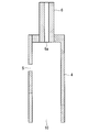
- FIG. 3 is an enlarged cross-sectional view showing the configuration of the first chamber 2 and the components 1 and 3 connected to the first chamber 2 shown in FIG. 4 is an enlarged cross-sectional view showing the configuration of the second chamber 4 and the component member 6 connected to the second chamber 4 shown in FIG.
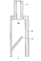
- FIG. 5 is an enlarged cross-sectional view showing the configuration of the third chamber 12 and the constituent member 14 connected to the third chamber 12 shown in FIG.
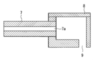
- FIG. 6 is an enlarged cross-sectional view showing the configuration of the fourth chamber 8 and the component member 7 connected to the fourth chamber 8 shown in FIG.
- the solution spray section is composed of four chambers 2, 4, 8, and 12, and the chambers 2, 4, 8, and 12 are partitioned by wall surfaces. That is, as shown in the configuration example of FIG. 1, each of the chambers 2, 4, 8, and 12 is surrounded by a wall surface so that an accommodation space is formed.
- the first chamber 2 is adjacent to the second chamber 4 in the X direction (right direction in FIG. 1).
- the second chamber 4 is adjacent to the third chamber 12 in the X direction (right direction in FIG. 1). That is, in the X direction, the first chamber 2, the second chamber 4, and the third chamber 12 are adjacent to each other in that order.
- the first chamber 2 is adjacent to the fourth chamber 8 in the ⁇ Z direction (downward in FIG. 1).
- the first chamber 2 has a rectangular plan view shape extending in the Y direction. As shown in FIGS. 1 and 3, the first chamber 2 is surrounded by a wall surface so that an accommodation space is formed. That is, a closed space is formed in the first chamber 2 by arranging wall surfaces on the top, bottom, left, and right of the first chamber 2.
- the wall of the first chamber 2 adjacent to the second chamber 4 has a through hole 5 connecting the first chamber 2 and the second chamber 4. Is drilled.
- the number of the through holes 5 may be one or plural.
- the opening shape of the through-hole 5 can employ
- a spray nozzle 1 for injecting the dropletized solution is provided.
- a solution formed into droplets by the “spray method” is ejected from the ejection port 1 a of the spray nozzle 1. That is, droplets having a size of about several tens of ⁇ m are ejected from the spray nozzle 1.
- the spray nozzle 1 for example, the above-described two-fluid spray nozzle can be employed.
- the solution contains a raw material material for a film formed on the substrate 50.
- a switching valve 16 is disposed in the middle of the spray nozzle 1, and a cleaning liquid supply nozzle 17 is connected to the switching valve 16.
- a cleaning liquid for cleaning the inside of the spray nozzle 1 is ejected from the cleaning liquid supply port of the cleaning liquid supply nozzle 17.
- a plurality of holes are formed in the wall surface on the upper surface side of the first chamber 2, and the tip of the spray nozzle 1 (the portion of the spray nozzle 1 downstream from the switching valve 16) is inserted into the hole. ing.
- a plurality of spray nozzles 1 may be connected to the upper surface of the first chamber 2 (in the configuration example of FIG. 2, the spray nozzles 1 are arranged along the Y direction).
- the spray nozzles 1 may be connected to the upper surface of the first chamber 2. Further, in a state where the spray nozzle 1 is connected to the first chamber 2, a hole formed in the upper surface of the first chamber 2 (an insertion hole for the spray nozzle 1) is ensured to be sealed.
- the tip of the spray nozzle 1 penetrates the wall surface on the upper surface side of the first chamber 2, and the injection port 1 a of the spray nozzle 1 exists in the first chamber 2.
- the droplet-formed (several tens of ⁇ m) solution is sprayed from the spray port 1 a of the spray nozzle 1 into the first chamber 2, and the sprayed solution enters the first chamber 2. Be contained.
- a plurality of first gas supply nozzles 3 are provided. Gas is ejected from the first gas supply port 3 a of the first gas supply nozzle 3.
- a plurality of holes are formed in the left wall surface of the first chamber 2, and the tip of the first gas supply nozzle 3 is inserted into the hole.
- a plurality of first gas supply nozzles 3 may be connected to the side surface of the first chamber 2 (in the configuration example of FIG. 2, along the Y direction).
- the first gas supply nozzles 3 are arranged at a predetermined interval), and one first gas supply nozzle 3 may be connected to the side surface of the first chamber 2. .
- the gas ejected from the first gas supply port 3a of the first gas supply nozzle 3 collides with the dropletized solution existing in the first chamber 2.
- the first gas supply port 3a may be directed toward the solution sprayed from the spray nozzle 1 so that the solution sprayed from the spray nozzle 1 and the gas sprayed from the first gas supply nozzle 3 collide with each other. desirable.
- the solution in a droplet state is misted. That is, a mist-like solution having a size of about several ⁇ m is generated in the first chamber 2 by the collision.
- a through-hole 5 communicating with the second chamber 4 is formed on the right side surface of the first chamber 2.
- the mist solution is guided to the through hole 5 by riding on the gas ejected from the first gas supply nozzle 3. That is, it is desirable that the through hole 5 is disposed on an extension line in the injection direction of the gas injected from the first gas supply nozzle 3.
- a temperature adjusting unit 15 capable of adjusting the temperature is disposed in the wall surface on the upper surface side of the first chamber 2.
- the temperature adjusting unit 15 is disposed near the tip of the spray nozzle 1 and can set the tip to a predetermined temperature.
- the second chamber 4 has a rectangular plan view shape extending in the Y direction in the same manner as the first chamber 2 (in the configuration example of FIG. 2, Y of the first chamber 2 is The dimension in the direction and the dimension in the Y direction of the second chamber 4 are the same, and the end portions are aligned).
- the second chamber 4 is surrounded by a wall surface except for the lower surface so that an accommodation space is formed. That is, by arranging the wall surfaces on the upper and left sides of the second chamber 4, a closed space other than the lower surface is formed in the second chamber 4.
- An opened spraying port 10 is formed on the lower surface of the second chamber 4.
- the spray port 10 faces the main surface of the substrate 50 placed on the substrate platform 60 outside the second chamber 4 with a predetermined distance (see FIG. 1). Therefore, the misted solution is sprayed from the spray port 10 onto the main surface of the substrate 50.
- the spray port 10 is a rectangular opening (slit shape) extending in the Y direction.
- the wall of the second chamber 4 adjacent to the first chamber 2 is provided with a through hole 5 that connects the first chamber 2 and the second chamber 4. ing.
- a plurality of second gas supply nozzles 6 are provided. Gas is injected from the second gas supply port 6 a of the second gas supply nozzle 6.
- a plurality of holes are formed in the wall surface on the upper surface side of the second chamber 4, and the tip of the second gas supply nozzle 6 is inserted into the hole.
- a plurality of second gas supply nozzles 6 may be connected to the upper surface of the second chamber 4 (in the configuration example of FIG. 2, along the Y direction).
- the second gas supply nozzles 6 are arranged in a line at a predetermined interval), and one second gas supply nozzle 6 may be connected to the upper surface of the second chamber 4. .
- a hole an insertion hole for the second gas supply nozzle 6 drilled in the upper surface of the second chamber 4 is A sealed state is secured.
- the mist solution in the first chamber 2 is carried into the second chamber 4 and stored. And the gas injected from the said 2nd gas supply port 6a guides the mist-ized solution accommodated in the 2nd chamber 2 to the spraying port 10 side.
- the third chamber 12 has a rectangular plan view shape extending in the Y direction, like the first chamber 2 and the second chamber 4 (in the configuration example of FIG. 2,
- the dimension of the one chamber 2 in the Y direction, the dimension of the second chamber 4 in the Y direction, and the dimension of the third chamber 12 in the Y direction are the same, and the ends are aligned in each).
- the third chamber 12 is surrounded by a wall surface except the lower surface so that an accommodation space is formed. That is, by arranging the wall surfaces on the upper and left sides of the third chamber 12, a closed space is formed in the third chamber 12 except for the lower surface.
- An open exhaust port 11 is formed on the lower surface of the third chamber 12.
- the exhaust port 11 faces the main surface of the substrate 50 placed on the substrate platform 60 outside the third chamber 12 with a predetermined distance (see FIG. 1). Therefore, the unreacted liquid or gas existing above the substrate 50 is sucked from the exhaust port 11.
- the exhaust port 11 is a rectangular opening (slit shape) extending in the Y direction. As shown in FIG. 1, the exhaust port 11 is adjacent to the right side of the spray port 10, and the height position of the spray port 10 and the height position of the exhaust port 11 are the same.
- a plurality of exhaust nozzles 14 are provided.
- a suction force works from the exhaust hole 14a of the exhaust nozzle 14.
- a plurality of holes are formed in the wall surface on the upper surface side of the third chamber 12, and the tip of the exhaust nozzle 14 is inserted into the hole.
- a plurality of exhaust nozzles 14 may be connected to the upper surface of the third chamber 12 (in the configuration example of FIG. 2, the exhaust nozzles 14 extend along the Y direction).
- the exhaust nozzles 14 may be connected to the upper surface of the third chamber 12.
- a hole formed in the upper surface of the third chamber 12 is sealed.
- a partition plate 13 extending obliquely upward is disposed in the third chamber 12.
- One end of the partition plate 13 is connected to one side surface of the third chamber 12, but the other end of the partition plate 13 is not connected to the other side surface of the third chamber 12.
- the gas / liquid existing above the substrate 50 is sucked up from the exhaust port 11 by the suction force from the exhaust nozzle 14. Due to the presence of the partition plate 13, the gas / liquid or the like sucked from the exhaust port 11 existing above the partition plate 13 in the third chamber 12 is prevented from falling to the exhaust port 11 side.
- the fourth chamber 8 is disposed on the lower surface side of the first chamber 2 and has a rectangular plan view shape extending in the Y direction (as in the first chamber 2).
- the dimension in the Y direction and the dimension in the Y direction of the fourth chamber 8 are the same, and the end portions are aligned).
- the fourth chamber 8 is surrounded by a wall surface so that an accommodation space is formed. That is, a closed space is formed in the fourth chamber 8 by arranging the wall surfaces on the top, bottom, left, and right of the fourth chamber 8.
- a third gas supply port 9 is formed in the lower wall surface of the fourth chamber 8.
- the third gas supply port 9 faces the main surface of the substrate 50 placed on the substrate platform 60 outside the fourth chamber 8 with a predetermined distance (see FIG. 1). Therefore, gas is ejected from the third gas supply port 9 toward the upper side of the substrate 50.
- the third gas supply port 9 is a rectangular opening (slit shape) extending in the Y direction. As shown in FIG. 1, the third gas supply port 9 is adjacent to the left side of the spray port 10, and the height position of the spray port 10 and the height position of the third gas supply port 9 are the same. is there.
- a plurality of third gas supply nozzles 7 are provided. A gas is ejected from the ejection port 7 a of the third gas supply nozzle 9 into the fourth chamber 8.
- a plurality of holes are formed in the side wall of the fourth chamber 8, and the tip of the third gas supply nozzle 7 is inserted through the hole.
- a plurality of third gas supply nozzles 7 may be connected to the side surface of the fourth chamber 8 (in the configuration example of FIG. 2, along the Y direction).
- the third gas supply nozzles 7 may be connected to the side surface of the fourth chamber 8.
- the third gas supply nozzles 7 may be connected to the side surface of the fourth chamber 8. Further, in a state where the third gas supply nozzle 7 is connected to the fourth chamber 8, a hole (an insertion hole for the third gas supply nozzle 7) drilled in the side surface of the fourth chamber 8 is A sealed state is secured.
- the gas injected from the third gas supply nozzle 7 is accommodated in the fourth chamber 8, and the third gas supply port 9 drilled in the fourth chamber 8 passes through the upper surface of the substrate 50. Is injected.
- the film forming apparatus is provided with a substrate mounting portion 60 on which the substrate 50 is mounted.
- the substrate placement unit 60 moves in the left-right direction (X direction) in FIG. 1 with the substrate 50 placed (if it is a movement in the horizontal direction). That is, the substrate 50 moves in the horizontal direction by the above movement of the substrate platform 60 while the solution mist in the vertical direction is sprayed from the spray port 10 onto the substrate 50.
- a heater is disposed in the substrate platform 60. Therefore, the substrate 50 placed on the substrate platform 60 is heated to a predetermined temperature (film formation temperature) by the heater.
- the substrate 50 is placed on the substrate platform 60. And the board
- a spray-like solution (droplet solution) is ejected from the spray nozzle 1 into the first chamber 2.
- the switching valve 16 is switched in one direction, and the cleaning liquid supply port of the cleaning liquid supply nozzle 17 is closed. Therefore, only the solution flows through the liquid passage in the spray nozzle 1. From the first gas supply port 3 a, gas is ejected to the spray-like solution existing in the first chamber 2.
- the mist-like solution rides on the gas ejected from the first gas supply port 3 a and is guided into the second chamber 4 through the through hole 5.
- the mist solution rides on the gas ejected from the second gas supply port 6 a and is guided in the direction of the ejection port 10.
- a mist-like solution is sprayed from the spray port 10 onto the upper surface of the substrate 50.
- the gas is ejected from the third gas supply port 9 toward the upper surface of the substrate 50.
- the gas ejected from the third gas supply port 9 is supplied from the third gas supply nozzle 7 into the fourth chamber 8. Due to the ejection of gas from the third gas supply port 9, it is possible to prevent the solution sprayed from the spray port 10 from leaking to the left side from the third gas supply port 9. That is, the gas from the third gas supply port 9 functions as a “screen” for the solution sprayed from the spray port 10.
- the flow from the third gas supply port 9 toward the exhaust port 11 is generated by the suction force from the exhaust port 11. Therefore, the gas injected from the third gas supply port 9 generates a flow that moves toward the exhaust port 11 on the upper surface side of the substrate 50.
- the substrate platform 60 While performing the spraying of the solution from the spraying port 10, the suction from the exhaust port 11, and the ejection of the gas from the third gas supply port 9 as described above, the substrate platform 60 is moved in the X direction. As a result, the solution sprayed from the spray port 10 reacts with the atmosphere, and a uniform film is formed over the entire upper surface of the heated substrate 50.
- the solution ejected from the spray nozzle 1 is arbitrarily selected according to the film to be formed.
- any gas can be selected from the nozzles 3, 6 and 7 to be ejected.
- an inert gas is sprayed from the first gas supply port 3a and the second gas supply port 6a, and the third gas.
- an oxidizing agent for example, a fluid containing water, oxygen, ozone, or the like
- an inert gas is sprayed from the first gas supply port 3a, and oxidation is performed from the second gas supply port 6a.
- An agent for example, oxygen or ozone
- air may be injected from the third gas supply port 9.
- the film forming apparatus includes the first chamber 2 that can store the dropletized solution ejected from the spray nozzle 1. And the 1st gas supply port 3a which injects the gas made to collide with the solution which exists in the 1st chamber 2 and the 2nd chamber 4 adjacent to the 1st chamber 2 are provided.
- the wall surface existing between the first chamber 2 and the second chamber 4 is provided with a through hole 5 through which the mist solution flows. Then, the film forming apparatus is disposed with respect to the second chamber 4 so as to face the substrate 50 disposed outside the second chamber 4, and the mist solution of the substrate 50 is formed.
- a spraying port 10 for spraying is provided.
- the dropletized solution ejected by the spray nozzle 1 is misted in the first chamber 2 by collision with the gas ejected from the first gas supply port 3a. can do. Therefore, the spray-like solution can be made into a mist without directly contacting the substrate 50, and the mist-like solution is sprayed on the substrate 50, so that a CVD-like film formation can be performed in the atmosphere. It becomes possible. Therefore, the film forming apparatus can form a film with good film quality on the substrate 50.
- the spray solution is misted in the first chamber 2 in the vicinity of the spray port 10 for the solution substrate 50. Therefore, the transport distance of the mist-like solution can be made extremely shorter than the film forming apparatus employing the conventional “mist method” technique. Therefore, aggregation during the movement of the mist-like solution can be suppressed.
- the solution can be effectively used for the film forming process, and the solution having a stable concentration can be sprayed on the substrate 50.
- the film forming apparatus according to the present invention after spraying a spray-like solution, the gas is collided to make the solution mist. That is, in the film forming apparatus according to the present invention, the configuration for mist formation of the solution is extremely simple, and an ultrasonic vibrator or the like is not necessary. Therefore, in the film forming apparatus according to the present invention, the entire apparatus can be reduced in size. Further, due to the simple configuration, the film forming apparatus according to the present invention also improves maintainability.
- the film forming apparatus according to the present invention can have both the improvement in film quality obtained by the mist method and the simple structure and high maintainability obtained by the spray method.
- the first chamber 2 can also prevent a large solution of liquid droplets ejected from the spray nozzle 1 from being scattered around.
- the second chamber 4 can also prevent the mist-like solution from being scattered around.
- the fourth chamber 8 can prevent the gas from being scattered around.
- the third chamber 12 enables exhaust processing in which liquid and gas are concentrated.
- the film forming apparatus further includes a second gas supply port 6 a for injecting a gas that guides the mist solution existing in the second chamber 4 to the spray port 10. Therefore, it is possible to generate a flow for supplying the mist solution to the substrate 50 side.
- the film forming apparatus further includes an exhaust port 11 disposed adjacent to the spray port 10. Accordingly, a flow from the spray port 10 toward the exhaust port 11 occurs. Therefore, the mist-like solution sprayed from the spray port 10 generates a flow that moves toward the exhaust port 11 on the upper surface side of the substrate 50.
- the film forming apparatus further includes a third gas supply port 9 that is disposed adjacent to the spray port 10 and injects a gas. It is possible to prevent the solution sprayed from the spray port 10 from leaking to the left side from the third gas supply port 9.
- each of the spray port 10, the exhaust port 11, and the third gas supply port 9 has a slit shape extending in the Y direction. Therefore, the mist-like solution accommodated in the second chamber 4 can be uniformly sprayed from the spray port 10, and the gas accommodated in the fourth chamber 8 can be uniformly sprayed from the third gas supply port 9.
- the exhaust from the exhaust port 11 is also uniformly performed along the Y direction.
- the spray nozzle 1 is disposed so as to penetrate the upper wall surface of the first chamber 2.
- the temperature adjustment part 15 is arrange
- the vicinity of the injection port 1a of the spray nozzle 1 can be maintained at a predetermined temperature. Therefore, aggregation of the solution in the vicinity of the injection port 1a of the spray nozzle 1 can be prevented, and the spray nozzle 1 can be prevented from being clogged.
- the film forming apparatus further includes a substrate mounting portion 60 that moves in the horizontal direction. Therefore, it is possible to form a film on the substrate 50 having a large area while fixing the constituent members on the solution spray side.
- the heater is arrange
- a moving mechanism for moving the structure composed of the spray nozzle 1, the switching valve 16 and the cleaning liquid supply nozzle 17 in the vertical and horizontal directions. Then, when cleaning the spray nozzle 1, the following operation is performed.
- the above structure is moved upward in FIG. 1 by the moving mechanism, and the tip of the spray nozzle 1 is pulled out from the upper wall surface of the first chamber 2. And the said structure is moved to the horizontal direction etc. by the said moving mechanism. Thereby, as shown in FIG. 7, the front-end
- the switching valve 16 is switched to the other direction, the cleaning liquid supply port of the cleaning liquid supply nozzle 17 is opened, and the fluid path of the spray nozzle 1 is closed on the upstream side of the switching valve 16. As a result, a situation is formed in which the cleaning liquid supply port that supplies the cleaning liquid to the fluid passage in the spray nozzle 1 is connected.
- the cleaning liquid When the cleaning liquid is supplied to the cleaning liquid supply nozzle 17, the cleaning liquid flows from the cleaning liquid supply port to the fluid passage in the spray nozzle 1, and thereby contamination caused by the solution in the fluid passage in the spray nozzle 1 can be cleaned. .
- the cleaning liquid output from the spray port 1 a of the spray nozzle 1 is stored in the container 30.
- the structure is moved by the moving mechanism, and the spray nozzle 1 is perforated on the upper wall surface of the first chamber 2 as shown in FIG. Insert through the provided hole. Then, only the cleaning liquid supply port of the cleaning liquid supply nozzle 17 that switches the switching valve 16 in one direction is closed, and a fluid path in which only the solution flows is formed in the spray nozzle 1.
- the spray nozzle 1 contaminated by the film forming process can be appropriately cleaned by the moving mechanism and the cleaning mechanism.
- the solution spray structure shown in FIG. 1 is arranged in an open space in the atmosphere, and the space between the solution spray structure and the substrate 50 is further moved by the horizontal movement of the substrate platform 60. Does not become a closed space.
- the presence of the exhaust port 11 generates a constant airflow in the space between the solution spray structure and the substrate 50 (that is, in an open space).
- the space between the solution spray structure and the substrate 50 is open, maintenance of the portion of the solution spray structure that faces the substrate 50 is easy. Furthermore, the gas which guides the mist-ized solution from the 2nd chamber 4 to the spraying port 10 (namely, board
Landscapes
- Chemical & Material Sciences (AREA)
- General Chemical & Material Sciences (AREA)
- Chemical Kinetics & Catalysis (AREA)
- Engineering & Computer Science (AREA)
- Materials Engineering (AREA)
- Mechanical Engineering (AREA)
- Metallurgy (AREA)
- Organic Chemistry (AREA)
- Dispersion Chemistry (AREA)
- Nozzles (AREA)
- Chemically Coating (AREA)
Abstract
Description
図1は、本実施の形態に係る成膜装置の要部部分(より具体的には、基板に溶液を噴霧する溶液噴霧部付近)の構成を示す断面図である。ここで、図1には、X-Y-Z方向を図示している。また、図2は、図1に示した構成を、図1の上方向から見た構成を示す平面図である。ここで、図2には、X-Y方向を図示している。また、図2では、図面簡略化のために、各構成部材16,17,60の図示を省略している。
1a 噴射口
2 第一の室
3 第一のガス供給ノズル
3a 第一のガス供給口
4 第二の室
5 貫通孔
6 第二のガス供給ノズル
6a 第二のガス供給口
7 第三のガス供給ノズル
8 第四の室
9 第三のガス供給口
10 噴霧口
11 排気口
12 第三の室
13 仕切り板
14 排気ノズル
15 温度調整部
16 切替バルブ
17 洗浄液供給ノズル
30 容器
50 基板
60 基板載置部
Claims (13)
- 基板(50)に対して膜を成膜する成膜装置であって、
液滴化された溶液を噴射するスプレーノズル(1)と、
前記スプレーノズルから噴射される液滴化された前記溶液を収容することが可能な第一の室(2)と、
前記第一の室内に存する前記溶液に対して衝突させる気体を噴射する第一のガス供給口(3a)と、
前記第一の室に隣接している第二の室(4)と、
前記第一の室と前記第二の室との間に存する壁面に穿設され、前記第一のガス供給口から噴射された前記気体の衝突を受けることによりミスト化された前記溶液を、前記第一の室から前記第二の室に導く貫通孔(5)と、
前記第二の室の外側に配置された前記基板に面するように、前記第二の室に対して配設され、前記基板に対してミスト化された前記溶液の噴霧を行う噴霧口(10)とを、備えている、
ことを特徴とする成膜装置。 - 前記第二の室に存するミスト化された前記溶液を、前記噴霧口へと導く気体を噴射する第二のガス供給口(6a)を、さらに備えている、
ことを特徴とする請求項1に記載の成膜装置。 - 前記基板に面しており、前記噴霧口と一方側面側において隣接して配設されており、排気を行う排気口(11)を、さらに備えている、
ことを特徴とする請求項2に記載の成膜装置。 - 前記基板に面しており、前記噴霧口と他方側面側において隣接して配設されており、気体を噴射する第三のガス供給口(9)を、さらに備えている、
ことを特徴とする請求項3に記載の成膜装置。 - 前記噴霧口は、
長方形の開口部である、
ことを特徴とする請求項1に記載の成膜装置。 - 前記排気口は、
長方形の開口部である、
ことを特徴とする請求項3に記載の成膜装置。 - 前記第三のガス供給口は、
長方形の開口部である、
ことを特徴とする請求項4に記載の成膜装置。 - 前記スプレーノズルは、
前記第一の室の壁面を貫通するように配設されており、
前記スプレーノズルが貫通している前記壁面には、温度調整が可能な温度調整部(15)が配設されている、
ことを特徴とする請求項1に記載の成膜装置。 - 前記スプレーノズルは、
移動可能であり、
前記スプレーノズルには、
前記スプレーノズル内の流体通路に洗浄液を供給する洗浄液供給口が、配設されている、
ことを特徴とする請求項1に記載の成膜装置。 - 前記基板が載置され、前記噴霧口に対して、水平方向に移動する基板載置部(60)を、さらに備えている、
ことを特徴とする請求項1に記載の成膜装置。 - 前記基板載置部には、
ヒータが配設されている、
ことを特徴とする請求項10に記載の成膜装置。 - 前記スプレーノズルから、
酸素と反応する前記溶液を噴射し、
前記第一のガス供給口からは、
不活性ガスを噴射し、
前記第二のガス供給口からは、
不活性ガスを噴射し、
前記第三のガス供給口からは、
酸化剤を噴射する、
ことを特徴とする請求項4に記載の成膜装置。 - 前記スプレーノズルから、
酸素と反応する前記溶液を噴射し、
前記第一のガス供給口からは、
不活性ガスを噴射し、
前記第二のガス供給口からは、
酸化剤を噴射する、
ことを特徴とする請求項2に記載の成膜装置。
Priority Applications (8)
| Application Number | Priority Date | Filing Date | Title |
|---|---|---|---|
| KR1020157010105A KR101764987B1 (ko) | 2012-11-05 | 2012-11-05 | 성막 장치 |
| HK15107152.2A HK1206676B (en) | 2012-11-05 | Film-forming apparatus | |
| CN201280076801.5A CN104755174B (zh) | 2012-11-05 | 2012-11-05 | 成膜装置 |
| PCT/JP2012/078580 WO2014068778A1 (ja) | 2012-11-05 | 2012-11-05 | 成膜装置 |
| US14/440,000 US10458017B2 (en) | 2012-11-05 | 2012-11-05 | Film-forming apparatus to form a film on a substrate |
| JP2014544189A JP5914690B2 (ja) | 2012-11-05 | 2012-11-05 | 成膜装置 |
| EP12887704.0A EP2915588B1 (en) | 2012-11-05 | 2012-11-05 | Film-forming apparatus |
| TW102104527A TWI466728B (zh) | 2012-11-05 | 2013-02-06 | 成膜裝置 |
Applications Claiming Priority (1)
| Application Number | Priority Date | Filing Date | Title |
|---|---|---|---|
| PCT/JP2012/078580 WO2014068778A1 (ja) | 2012-11-05 | 2012-11-05 | 成膜装置 |
Publications (1)
| Publication Number | Publication Date |
|---|---|
| WO2014068778A1 true WO2014068778A1 (ja) | 2014-05-08 |
Family
ID=50626741
Family Applications (1)
| Application Number | Title | Priority Date | Filing Date |
|---|---|---|---|
| PCT/JP2012/078580 Ceased WO2014068778A1 (ja) | 2012-11-05 | 2012-11-05 | 成膜装置 |
Country Status (7)
| Country | Link |
|---|---|
| US (1) | US10458017B2 (ja) |
| EP (1) | EP2915588B1 (ja) |
| JP (1) | JP5914690B2 (ja) |
| KR (1) | KR101764987B1 (ja) |
| CN (1) | CN104755174B (ja) |
| TW (1) | TWI466728B (ja) |
| WO (1) | WO2014068778A1 (ja) |
Cited By (7)
| Publication number | Priority date | Publication date | Assignee | Title |
|---|---|---|---|---|
| CN104391433A (zh) * | 2014-12-05 | 2015-03-04 | 合肥鑫晟光电科技有限公司 | 一种喷淋系统及其使用方法 |
| WO2016051559A1 (ja) * | 2014-10-01 | 2016-04-07 | 東芝三菱電機産業システム株式会社 | 成膜装置 |
| WO2017068625A1 (ja) * | 2015-10-19 | 2017-04-27 | 東芝三菱電機産業システム株式会社 | 成膜装置 |
| WO2017068624A1 (ja) * | 2015-10-19 | 2017-04-27 | 東芝三菱電機産業システム株式会社 | 成膜装置 |
| JP2017176948A (ja) * | 2016-03-29 | 2017-10-05 | 東芝三菱電機産業システム株式会社 | 成膜装置 |
| JP2017176949A (ja) * | 2016-03-29 | 2017-10-05 | 東芝三菱電機産業システム株式会社 | 成膜装置 |
| JP2018114504A (ja) * | 2018-04-17 | 2018-07-26 | 東芝三菱電機産業システム株式会社 | 成膜装置 |
Families Citing this family (7)
| Publication number | Priority date | Publication date | Assignee | Title |
|---|---|---|---|---|
| CN108699692B (zh) * | 2016-04-26 | 2021-03-02 | 东芝三菱电机产业系统株式会社 | 成膜装置 |
| KR200485392Y1 (ko) | 2016-12-07 | 2018-01-31 | 주식회사 나래나노텍 | 개선된 저온 미스트 cvd 장치 |
| JP6863474B2 (ja) * | 2017-11-30 | 2021-04-21 | 株式会社島津製作所 | マトリックス膜形成装置 |
| CN110017420B (zh) * | 2018-01-09 | 2020-10-27 | 宝山钢铁股份有限公司 | 一种气动阀门的缸体自润滑装置 |
| JP7571514B2 (ja) * | 2020-12-14 | 2024-10-23 | 住友ベークライト株式会社 | 生体用薬液注入用具 |
| CN115613005A (zh) * | 2021-07-16 | 2023-01-17 | 长鑫存储技术有限公司 | 雾化装置与薄膜沉积系统 |
| CN113578559A (zh) * | 2021-08-27 | 2021-11-02 | 深圳市鑫王牌科技发展有限公司 | 喷嘴及喷雾设备 |
Citations (4)
| Publication number | Priority date | Publication date | Assignee | Title |
|---|---|---|---|---|
| JP2001327898A (ja) * | 2000-05-24 | 2001-11-27 | Tdk Corp | 霧化方法及び装置、並びに固液混合方法及び装置 |
| JP2005307238A (ja) | 2004-04-19 | 2005-11-04 | Shizuo Fujita | 成膜方法及び成膜装置 |
| JP2007144297A (ja) | 2005-11-28 | 2007-06-14 | Masaharu Kaneko | 薄膜形成方法 |
| JP2011167675A (ja) * | 2010-02-22 | 2011-09-01 | Nanoplanet Corp | 旋回ミスト発生装置及び旋回ミストの発生方法 |
Family Cites Families (17)
| Publication number | Priority date | Publication date | Assignee | Title |
|---|---|---|---|---|
| US3382845A (en) * | 1964-07-21 | 1968-05-14 | Avisun Corp | Separating liquid droplets in spray coating operation |
| JP2838536B2 (ja) * | 1989-04-12 | 1998-12-16 | ノードソン株式会社 | 顔料又は染料の調色塗布方法 |
| US6409839B1 (en) * | 1997-06-02 | 2002-06-25 | Msp Corporation | Method and apparatus for vapor generation and film deposition |
| DE19730617A1 (de) * | 1997-07-17 | 1999-01-21 | Abb Research Ltd | Druckzerstäuberdüse |
| US6322003B1 (en) * | 1999-06-11 | 2001-11-27 | Spraying Systems Co. | Air assisted spray nozzle |
| JP2001321701A (ja) | 2000-03-08 | 2001-11-20 | Dyflex Corp | スプレーガン |
| DE50110876D1 (de) * | 2000-08-17 | 2006-10-12 | Knorr Bremse Systeme | Festsattel-scheibenbremse |
| JP4293035B2 (ja) | 2003-05-07 | 2009-07-08 | セイコーエプソン株式会社 | 撥液膜被覆部材、液体噴出装置の構成部材、液体噴出ヘッドのノズルプレート、液体噴出ヘッドおよび液体噴出装置 |
| JP3990322B2 (ja) * | 2003-06-18 | 2007-10-10 | 株式会社東芝 | 基板乾燥方法及び装置 |
| JP4494840B2 (ja) * | 2003-06-27 | 2010-06-30 | 大日本スクリーン製造株式会社 | 異物除去装置、基板処理装置および基板処理方法 |
| TWI415689B (zh) | 2006-08-17 | 2013-11-21 | 半導體能源研究所股份有限公司 | 成膜方法、液滴排出方法以及液滴排出裝置 |
| CN101462095A (zh) * | 2007-12-21 | 2009-06-24 | 穆兴叶 | 热气喷塑技术 |
| JP2010247106A (ja) | 2009-04-17 | 2010-11-04 | Nozzle Network Co Ltd | 微細化促進用の気液混合ノズル装置 |
| FI9160U1 (fi) | 2010-01-04 | 2011-04-14 | Beneq Oy | Pinnoituslaite |
| US8511583B2 (en) * | 2010-02-05 | 2013-08-20 | Msp Corporation | Fine droplet atomizer for liquid precursor vaporization |
| CN103314134B (zh) * | 2011-03-15 | 2015-07-15 | 东芝三菱电机产业系统株式会社 | 成膜装置 |
| DE112011105618T5 (de) * | 2011-09-13 | 2014-06-18 | Toshiba Mitsubishi-Electric Industrial Systems Corp. | Oxidfilm-Niederschlagsverfahren und Oxidfilm-Niederschlagsvorrichtung |
-
2012
- 2012-11-05 EP EP12887704.0A patent/EP2915588B1/en active Active
- 2012-11-05 WO PCT/JP2012/078580 patent/WO2014068778A1/ja not_active Ceased
- 2012-11-05 KR KR1020157010105A patent/KR101764987B1/ko active Active
- 2012-11-05 CN CN201280076801.5A patent/CN104755174B/zh active Active
- 2012-11-05 JP JP2014544189A patent/JP5914690B2/ja active Active
- 2012-11-05 US US14/440,000 patent/US10458017B2/en active Active
-
2013
- 2013-02-06 TW TW102104527A patent/TWI466728B/zh active
Patent Citations (4)
| Publication number | Priority date | Publication date | Assignee | Title |
|---|---|---|---|---|
| JP2001327898A (ja) * | 2000-05-24 | 2001-11-27 | Tdk Corp | 霧化方法及び装置、並びに固液混合方法及び装置 |
| JP2005307238A (ja) | 2004-04-19 | 2005-11-04 | Shizuo Fujita | 成膜方法及び成膜装置 |
| JP2007144297A (ja) | 2005-11-28 | 2007-06-14 | Masaharu Kaneko | 薄膜形成方法 |
| JP2011167675A (ja) * | 2010-02-22 | 2011-09-01 | Nanoplanet Corp | 旋回ミスト発生装置及び旋回ミストの発生方法 |
Non-Patent Citations (1)
| Title |
|---|
| See also references of EP2915588A4 |
Cited By (16)
| Publication number | Priority date | Publication date | Assignee | Title |
|---|---|---|---|---|
| WO2016051559A1 (ja) * | 2014-10-01 | 2016-04-07 | 東芝三菱電機産業システム株式会社 | 成膜装置 |
| KR101958122B1 (ko) * | 2014-10-01 | 2019-03-13 | 도시바 미쓰비시덴키 산교시스템 가부시키가이샤 | 성막 장치 |
| US10118191B2 (en) | 2014-10-01 | 2018-11-06 | Toshiba Mitsubishi-Electric Industrial Systems Corporation | Film forming apparatus |
| JPWO2016051559A1 (ja) * | 2014-10-01 | 2017-04-27 | 東芝三菱電機産業システム株式会社 | 成膜装置 |
| KR20170053659A (ko) * | 2014-10-01 | 2017-05-16 | 도시바 미쓰비시덴키 산교시스템 가부시키가이샤 | 성막 장치 |
| CN107073487A (zh) * | 2014-10-01 | 2017-08-18 | 东芝三菱电机产业系统株式会社 | 成膜装置 |
| CN104391433A (zh) * | 2014-12-05 | 2015-03-04 | 合肥鑫晟光电科技有限公司 | 一种喷淋系统及其使用方法 |
| WO2017068624A1 (ja) * | 2015-10-19 | 2017-04-27 | 東芝三菱電機産業システム株式会社 | 成膜装置 |
| CN108138320B (zh) * | 2015-10-19 | 2020-11-03 | 东芝三菱电机产业系统株式会社 | 成膜装置 |
| JPWO2017068625A1 (ja) * | 2015-10-19 | 2018-03-01 | 東芝三菱電機産業システム株式会社 | 成膜装置 |
| JPWO2017068624A1 (ja) * | 2015-10-19 | 2018-03-01 | 東芝三菱電機産業システム株式会社 | 成膜装置 |
| CN108138320A (zh) * | 2015-10-19 | 2018-06-08 | 东芝三菱电机产业系统株式会社 | 成膜装置 |
| WO2017068625A1 (ja) * | 2015-10-19 | 2017-04-27 | 東芝三菱電機産業システム株式会社 | 成膜装置 |
| JP2017176949A (ja) * | 2016-03-29 | 2017-10-05 | 東芝三菱電機産業システム株式会社 | 成膜装置 |
| JP2017176948A (ja) * | 2016-03-29 | 2017-10-05 | 東芝三菱電機産業システム株式会社 | 成膜装置 |
| JP2018114504A (ja) * | 2018-04-17 | 2018-07-26 | 東芝三菱電機産業システム株式会社 | 成膜装置 |
Also Published As
| Publication number | Publication date |
|---|---|
| US20150299854A1 (en) | 2015-10-22 |
| JP5914690B2 (ja) | 2016-05-11 |
| KR20150055067A (ko) | 2015-05-20 |
| KR101764987B1 (ko) | 2017-08-03 |
| HK1206676A1 (en) | 2016-01-15 |
| EP2915588B1 (en) | 2020-08-26 |
| CN104755174B (zh) | 2017-08-04 |
| TWI466728B (zh) | 2015-01-01 |
| JPWO2014068778A1 (ja) | 2016-09-08 |
| US10458017B2 (en) | 2019-10-29 |
| TW201418894A (zh) | 2014-05-16 |
| EP2915588A4 (en) | 2016-07-06 |
| EP2915588A1 (en) | 2015-09-09 |
| CN104755174A (zh) | 2015-07-01 |
Similar Documents
| Publication | Publication Date | Title |
|---|---|---|
| JP5914690B2 (ja) | 成膜装置 | |
| JP5529340B2 (ja) | 成膜装置 | |
| JP2018012343A (ja) | 高高度インクジェット印刷 | |
| KR101010032B1 (ko) | 이류체 슬릿 노즐 및 그 제조 방법 | |
| JP2015044192A (ja) | 静電気力を用いる噴霧およびパターニング装置 | |
| CN102842522A (zh) | 双流体喷嘴、基板液处理装置和基板液处理方法 | |
| JP6464808B2 (ja) | 液体噴射装置 | |
| WO2016051559A1 (ja) | 成膜装置 | |
| KR102193365B1 (ko) | 성막 장치 | |
| HK1206676B (en) | Film-forming apparatus | |
| JP5399053B2 (ja) | インクジェット塗布装置のノズルヘッド洗浄装置、これを備えたインクジェット塗布装置のノズルワイピング装置 | |
| JP2007059416A (ja) | 基板処理装置 | |
| CN101185920A (zh) | 流体喷射装置 | |
| KR102173962B1 (ko) | 성막 장치 | |
| JP2019018139A (ja) | 洗浄装置 | |
| KR100846575B1 (ko) | 평판 디스플레이 글라스 세정용 이류체 분사 장치 | |
| JP2019072700A (ja) | 薄膜製造装置 | |
| JP6466876B2 (ja) | 成膜装置 | |
| JP2017176949A (ja) | 成膜装置 | |
| WO2013037151A1 (zh) | 喷墨单元及喷墨设备 | |
| JP2018114504A (ja) | 成膜装置 | |
| HK1185923B (zh) | 成膜装置 | |
| JP2007117959A (ja) | 建築板の塗装装置 |
Legal Events
| Date | Code | Title | Description |
|---|---|---|---|
| 121 | Ep: the epo has been informed by wipo that ep was designated in this application |
Ref document number: 12887704 Country of ref document: EP Kind code of ref document: A1 |
|
| ENP | Entry into the national phase |
Ref document number: 2014544189 Country of ref document: JP Kind code of ref document: A |
|
| WWE | Wipo information: entry into national phase |
Ref document number: 2012887704 Country of ref document: EP |
|
| ENP | Entry into the national phase |
Ref document number: 20157010105 Country of ref document: KR Kind code of ref document: A |
|
| WWE | Wipo information: entry into national phase |
Ref document number: 14440000 Country of ref document: US |
|
| NENP | Non-entry into the national phase |
Ref country code: DE |