WO2014073252A1 - リアクトル装置 - Google Patents
リアクトル装置 Download PDFInfo
- Publication number
- WO2014073252A1 WO2014073252A1 PCT/JP2013/071566 JP2013071566W WO2014073252A1 WO 2014073252 A1 WO2014073252 A1 WO 2014073252A1 JP 2013071566 W JP2013071566 W JP 2013071566W WO 2014073252 A1 WO2014073252 A1 WO 2014073252A1
- Authority
- WO
- WIPO (PCT)
- Prior art keywords
- iron core
- coil
- magnetic leg
- core
- yoke
- Prior art date
- Legal status (The legal status is an assumption and is not a legal conclusion. Google has not performed a legal analysis and makes no representation as to the accuracy of the status listed.)
- Ceased
Links
Images

























Classifications
-
- H—ELECTRICITY
- H01—ELECTRIC ELEMENTS
- H01F—MAGNETS; INDUCTANCES; TRANSFORMERS; SELECTION OF MATERIALS FOR THEIR MAGNETIC PROPERTIES
- H01F27/00—Details of transformers or inductances, in general
- H01F27/24—Magnetic cores
- H01F27/25—Magnetic cores made from strips or ribbons
-
- H—ELECTRICITY
- H01—ELECTRIC ELEMENTS
- H01F—MAGNETS; INDUCTANCES; TRANSFORMERS; SELECTION OF MATERIALS FOR THEIR MAGNETIC PROPERTIES
- H01F27/00—Details of transformers or inductances, in general
- H01F27/24—Magnetic cores
- H01F27/26—Fastening parts of the core together; Fastening or mounting the core on casing or support
- H01F27/263—Fastening parts of the core together
-
- H—ELECTRICITY
- H01—ELECTRIC ELEMENTS
- H01F—MAGNETS; INDUCTANCES; TRANSFORMERS; SELECTION OF MATERIALS FOR THEIR MAGNETIC PROPERTIES
- H01F37/00—Fixed inductances not covered by group H01F17/00
-
- H—ELECTRICITY
- H01—ELECTRIC ELEMENTS
- H01F—MAGNETS; INDUCTANCES; TRANSFORMERS; SELECTION OF MATERIALS FOR THEIR MAGNETIC PROPERTIES
- H01F27/00—Details of transformers or inductances, in general
- H01F27/28—Coils; Windings; Conductive connections
- H01F27/30—Fastening or clamping coils, windings, or parts thereof together; Fastening or mounting coils or windings on core, casing, or other support
- H01F27/306—Fastening or mounting coils or windings on core, casing or other support
Definitions
- the present invention relates to a reactor device for removing harmonic components generated when DC power is converted into AC power using an inverter in a power controller system used for solar power generation, and more particularly to a reactor device using an amorphous material. .
- the iron core of a large-capacity three-phase reactor device is a reactor device using an amorphous material to reduce loss during operation (iron loss), and is described in Patent Document 1 (Japanese Patent Laid-Open No. 2008-218660). Yes.
- Patent Document 1 includes a toroidal iron core having a leg portion in which a plurality of ring-shaped core units are stacked in a magnetization direction and a coil, and a part or all of the core unit is made of an amorphous metal.
- the reactor device is disclosed.
- patent document 1 is disclosed about the structure of an iron core and a coil, and is not disclosed about the structure of the whole reactor apparatus.
- An object of the present invention is to provide a reactor device that uses an amorphous iron core and achieves low loss.
- the present application includes a plurality of means for solving the above-described problems.
- the present invention relates to a yoke core formed by winding an amorphous ribbon in a toroidal shape, and a magnetic leg core formed of an amorphous ribbon. And a coil wound around the magnetic leg iron core, the yoke iron core is disposed in a lower fitting, and the magnetic leg iron cores are stacked at equal intervals at three locations on the circumference of the yoke iron core.
- the coil core is inserted into the magnetic leg core, the yoke iron core is disposed above the magnetic leg core, the yoke core is covered with an upper clamp, and the circular lower clamp and the Three studs are arranged around the upper fastener at regular intervals, one stud is further arranged at the center, and the lower fastener and the upper fastener are fastened and fixed by the stud.
- the magnetic leg core is installed and fixed using a stud or the like, and the coil is fixed to the coil.
- the bracket can be installed and fixed with high precision, and the tripod can be balanced.
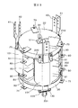
- FIG. 2A It is a perspective view which shows the structure for demonstrating the principle of the reactor apparatus using the amorphous iron core of this invention.
- the whole perspective view of the reactor apparatus using the amorphous iron core of this invention is shown.
- the whole reactor apparatus seen from the bottom part of FIG. 2A is shown.
- worn is shown.
- the perspective view of the reactor apparatus when the zero phase iron core of this invention, a magnetic leg iron core, and a coil are mounted is shown.
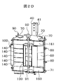
- the internal cross-sectional view of the reactor apparatus of FIG. 2A is shown.
- the external appearance perspective view of a yoke iron core, a magnetic leg iron core, and a zero phase iron core is shown.
- the perspective view of the process of mounting a laminated board and a yoke iron core to a lower clamp is shown.
- positioned at a lower clamp is shown.
- wearing a magnetic leg iron core is shown.
- the perspective view of the process of inserting and attaching a coil to a magnetic leg iron core is shown.
- the perspective view which attaches a coil to each of 3 legged magnetic cores is shown.
- wearing with a zero phase iron core is shown.
- the perspective view of the process of fixing a tripod coil is shown.
- wearing with a laminated board and a yoke iron core, and covering with an upper clamp is shown.
- wearing the eye nut which suspends a reactor apparatus is shown.
- the external appearance perspective view of the yoke iron core of Example 3, a magnetic leg iron core, and a zero phase iron core is shown.
- the perspective view of the process of mounting a laminated board and a yoke iron core to a lower clamp is shown.
- wearing a lower clamp with a zero phase iron core is shown.
- positioning a coil support bracket around a center stud is shown.
- wearing with a round magnetic leg iron core is shown.
- the perspective view of the process of inserting a coil in a magnetic leg iron core is shown.
- the perspective view of the state which attached the coil to the magnetic leg iron core of 3 legs is shown.
- wearing with the coil brace which fixes an upper part to a three-legged coil is shown.
- the perspective view of the process covered with an upper clamp from the upper direction of a laminated board and a yoke iron core is shown.
- wearing the eye nut which suspends a reactor apparatus is shown.
- the caster is attached to the base of the reactor device, and a perspective view in a completed state is shown.
- the perspective view of the structure which pulled out the coil terminal of Example 4 from the inner side of the reactor apparatus is shown.
- positioned the sound-absorbing material between the up-and-down fastener and the laminated board is shown.
- the perspective view of the structure which mounts a lower yoke iron core to a lower clamp is shown.
- positions a coil support bracket and an insulator in the center of a lower clamp is shown.
- (b) is a figure which shows the relationship of arrangement
- FIG. 1 It is a perspective view which shows the coil mounting
- the perspective view which mounts an upper yoke iron core in the upper part of a coil is shown.
- worn with all the components is shown.
- worn with all the components is shown.
- wore with all the components is shown.
- FIG. 29C is an external perspective view in which the mounting of the one leg magnetic core and the coil in FIG.
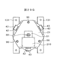
- FIG. 29C shows a top view of FIG. 29F.
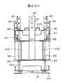
- FIG. 29F shows a front view of FIG. 29F.
- A) shows the top view at the time of attaching a coil fixing metal fitting
- (b) shows the external view of a coil fixing metal fitting. It is a perspective view which shows the coil fixing method of Example 11 of this invention.
- positioned the vent hole in the center of the upper clamp of Example 12 of this invention is shown. It is a longitudinal cross-sectional view of a reactor apparatus, and is a figure which shows the flow of air. It is a cross-sectional view of the coil portion of the reactor device and is a diagram showing the flow of air.
- positioned the fan in the center of the upper clamp of a reactor apparatus is shown.
- FIG. 35A It is a figure which shows the state of an overlap of a magnetic leg iron core and a yoke iron core. It is a figure which shows the arrangement
- the flowchart about the dimension setting of a magnetic leg iron core, a coil, and a yoke iron core is shown.
- the partial figure of the reactor apparatus accompanying the flowchart of FIG. 35A is shown.
- FIG. 1 is a perspective view showing a basic structure of a reactor device.
- 160 and 161 are yoke iron cores
- 140 are magnetic leg iron cores
- 100 are coils
- 60 is a zero-phase iron core.
- the yoke cores 160 and 161 are formed by winding an amorphous ribbon in a toroidal shape (annular shape) and having a circular thickness with a hollow.
- the magnetic leg iron core 140 has a fan shape.
- the fan-shaped shape include an amorphous ribbon wound in a toroidal shape, cut in the axial direction, formed into a fan-shaped shape, and a plurality of fan-shaped blocks stacked, or Example 13 A polygonal shape as described in FIG. 34B and FIG. 34C is included.
- This fan-shaped feature will be described in detail in the ninth and thirteenth embodiments.
- the amorphous ribbon is wound in a toroidal shape as in the former, cut in the axial direction, formed into a fan shape, and a plurality of fan-shaped blocks are stacked. I will explain.
- the inner and outer sides are circular like the yoke iron core, so when overlapping with the yoke iron core, the portion where the yoke iron core and leg iron core do not overlap is minimized. It is possible to prevent iron loss and useless increase in mass.
- the periphery of the magnetic leg iron core 140 is formed by winding the coil 100.
- the yoke cores 160 and 161 are disposed to face the upper and lower ends of the reactor device, and the three magnetic leg cores 140 and the coils 100 are disposed between the yoke cores 160 and 161, and the upper and lower yoke cores are magnetically connected. Connecting.
- the reason why the three coils 100 wound around the magnetic leg core 140 are provided is to allow the reactor device to function as a three-phase reactor device for three-phase AC. Further, the magnetic leg iron core 140 and the coil 100 are arranged in a positional relationship of approximately 120 degrees with respect to each other on the circumference of the yoke core with reference to the concentric axis of the circular yoke iron cores 160 and 161 having a hollow shape. This is to ensure electrical symmetry.
- the zero-phase iron core 60 is formed in a rectangular parallelepiped shape by laminating a plurality of rectangular amorphous ribbons, and the magnetic leg iron core is based on the concentric shafts of the hollow circular yoke irons 160 and 161. Are arranged on a circumference rotated by an angle of approximately 60 degrees from the position of 60 (approximately 120 degrees between the three zero-phase cores 60), and the yoke cores 160 and 161, Are magnetically connected.
- This zero-phase iron core 60 is installed as a path for flowing magnetic flux due to zero-phase impedance generated when the phase of the three-phase alternating current flowing in the coil 100 wound around the three magnetic leg cores 140 deviates from the ideal state. Yes.
- the above is the description of the basic structure of the reactor device of the present invention.
- the inner diameters of the yoke cores 160 and 161 wound in a toroidal shape are L1 (300), the thickness L2 (310) of the coil 100 wound around the magnetic leg iron core 141, and L1> 2 * L2 make a relationship.
- L1 300
- L2 310
- L1> 2 * L2 make a relationship.
- 10 is a reactor device
- 20 is an upper fastening bracket
- 30 is a lower fastening fixture
- 40 is an inner coil terminal
- 41 is an outer coil terminal
- 50 is a my nut for hanging the rear reactor body
- 60 is Zero-phase core
- 70 is a stud fixing bracket
- 80 is a zero-phase core support bracket
- 81 is a zero-phase core receiver
- 90 is a stud provided on the outer periphery of the reactor body
- 91 is a stud provided in the center of the reactor body
- 100 is A coil
- 120 is a coil clamp
- 130 is a base
- 140 is a magnetic leg iron core
- 150 is a coil support
- 152 is a coil stopper for stopping the coil support
- 160 and 161 are yoke cores.
- the magnetic leg iron core 140 has a narrow fan shape on the center axis side, the coil 100 is wound around the fan-shaped magnetic leg iron core 140, and the laminated plate 171 is placed on the upper side of the lower fastener 30.
- the magnetic leg iron core 140 and the coil 100 are arranged at intervals of 120 degrees.
- the magnetic leg iron core 140 is formed by stacking iron cores having a predetermined height, and a laminated plate is inserted between the magnetic leg iron cores.
- the coil 100 is wound around the entire magnetic leg iron core 140.
- the magnetic leg iron core 140 and the coil 100 are formed by being sandwiched between a yoke iron core 161 wound in a lower toroidal shape and a yoke iron core 160 wound in an upper toroidal shape.
- the lower yoke iron core 161 is housed and fixed in the case of the lower fastener 30, and the upper yoke core 160 is covered and fixed by the case of the upper fastener 20.
- the zero-phase iron core 60 is arrange
- the structure of the zero-phase iron core is formed by stacking rectangular amorphous ribbons into a rectangular parallelepiped shape and inserting it into a rectangular zero-phase core receiver 81 connected to a zero-phase core support fitting 80 installed on the stud 90. Is fixed.
- the zero-phase core 60 is formed by being sandwiched between the lower yoke core 161 and the upper yoke core 160 in the same manner as the magnetic leg core 140.
- the magnetic leg iron cores 140 and the zero-phase iron core 60 have the same height and are sandwiched between the yoke iron cores 160 and 161 so as to form magnetic paths, respectively.
- the distance between the iron core 140 and the yoke iron cores 160 and 161 needs to be adjusted with an accuracy of mm.
- the stud 90 that supports the zero-phase iron core 60 is formed on the outer periphery of the reactor main body 10 on which the zero-phase iron core is disposed, and all the shaft portions are threaded. Similarly, the center stud 91 is threaded on all the shaft portions. Further, the upper side of the stud 90 is fixed by tightening a stud fixing bracket 70 provided with a hole for a stud on a rectangular metal plate connected and fixed to the upper fastening bracket 20 by welding or the like with a lock nut. On the lower side, a stud fixing bracket 71 provided with a stud hole is fastened and fixed to a rectangular metal plate that is connected and fixed to the lower fastening bracket 30 by welding or the like.
- the stud 90 has two zero-phase core support fittings 80 each having a stud hole on a rectangular metal plate connected and fixed to a zero-phase core receiver 81 of a rectangular frame of a metal plate that receives the zero-phase core 60.
- the stud 90 is inserted through the hole of the zero-phase core support fitting 80 and fixed by a lock nut at a predetermined position.
- the stud 91 arranged in the center fastens the upper fastening bracket 20 and the lower fastening fixture 30, and the three studs 90 arranged on the outer periphery of the reactor body 10 also fasten and fix the upper fastening fixture 20 and the lower fastening fixture 30. is doing.
- an eye nut 50 that is used when the reactor body 10 is suspended is attached to the tip of the center stud 91.
- the coil 100 is pressed against a triangular coil support bracket 120 provided at the center of the reactor body 10 and fixed with a coil support bracket 150 from the outside.
- the coil support member 150 is an elongated rectangular metal plate and is formed of two pieces.
- a bolt is fixed to the side surface of the lower clamp 30 by welding or the like, and the bolt is also fixed to the side surface of the upper clamp 20 above the bolt.
- the lower piece is formed by bending one end of an elongated rectangular metal plate in a step shape to form a hole penetrating the bolt, and fixing the other end by welding the bolt to the bolt of the lower fastener 20.
- the hole of the metal fitting 150 is inserted and arranged.
- the upper metal fitting 20 and the lower piece of the bolt are bent into a stepped shape at the substantially central portion of the rectangular metal plate that is the upper piece, and a hole that penetrates the bolt is formed on each surface. , And fasten each with a lock nut.
- the lower metal fitting 30 is made of two pieces, but it may be made of one plate and made into one piece.
- the coil terminals 40 and 41 are drawn upward from the winding start and winding end of the coil 100 so that they can be connected to the power circuit of the power controller system. Further, the surface of the coil 100 is protected by winding an insulating paper.
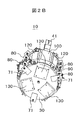
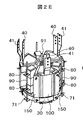
- FIG. 2F shows a top cross-sectional view of the center height of the reactor shown in FIG. 2E.
- the fan-shaped magnetic leg iron core 140 is wound around the coil 100 and arranged so that the outer circumference of the fan-shaped magnetic leg iron core 140 coincides with the outer circumference of the upper fastener 20 and the lower fastener 30.
- the outer peripheral portion of the fan-shaped coil is arranged so as to protrude from the upper and lower fasteners, and the arrangement interval is 120 degrees.
- a coil terminal is disposed on the outer peripheral side of the coil 100, and the inner terminal 40 and the outer terminal 41 are disposed at a predetermined distance.
- the magnetic leg iron core 140 and the center side of the coil 100 are not arcuate but linear, and are pressed against the triangular coil support 120 to be positioned and fixed with high accuracy.
- the center side of the coil 100 is linear, but it is also possible to make it arcuate and the coil support 120 can also be arcuate.
- the magnetic leg iron core 140 and the coil 100 are fixed at both ends of the outer periphery of the coil 100 on the side of the terminal with a coil fastener.
- the zero-phase iron core 60 is disposed between the coils 100, and the zero-phase iron cores are equally spaced by 120 degrees.
- the zero-phase iron core 60 is laminated so as to be parallel to each other by laminating rectangular elongated amorphous metal plates with respect to the center line axis of the circular reactor. Further, a zero-phase core support fitting 80 is disposed on the outer periphery of the zero-phase core 60 to support the zero-phase core 60.
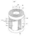
- FIG. 2A is an external view of the reactor device as viewed from the upper oblique direction
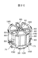
- FIG. 2B is an external view as viewed from the lower oblique direction.
- the coil 100 is fixed by tightening the upper and lower portions of the coil support bracket 150 and by tightening the upper and lower fasteners 20 and 30.
- the zero-phase iron core 60 is supported and fixed by zero-phase iron core support fittings 80 arranged at two locations on the stud 90.
- a stud fixing bracket 70 fixed to the upper fastener 20 and a stud fixing bracket 71 fixed to the lower fastener 30 are attached to the stud 90, and the upper fastener 20 and the lower fastener 30 are tightened and fixed. is doing.
- U-shaped bases 130 are arranged and fixed on the outer periphery of three locations at equal intervals.
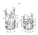
- FIGS. 3 to 12 show a manufacturing method of the reactor device when the fan-shaped magnetic leg iron core 140 is used.
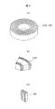
- FIG. 3A is a perspective view of yoke irons 160 and 161 arranged above and below the reactor 10 and configured to sandwich the magnetic leg iron core 140 and the zero-phase iron core 60.
- the yoke iron core in FIG. 3 (a) is concentric, but is actually a cylindrical shape having a hole in the center of an amorphous ribbon wound in a toroidal shape.
- FIG. 3A is a perspective view of yoke irons 160 and 161 arranged above and below the reactor 10 and configured to sandwich the magnetic leg iron core 140 and the zero-phase iron core 60.
- the yoke iron core in FIG. 3 (a) is concentric, but is actually a cylindrical shape having a hole in the center of an amorphous ribbon wound in a toroidal shape.
- FIG. 3B is an external perspective view of the magnetic leg iron core 140, in which an iron core obtained by winding an amorphous ribbon in a toroidal shape is cut in the axial direction to form a fan-shaped iron core.
- FIG. 3 (c) is an external perspective view of the zero-phase iron core 60, in which elongated rectangular amorphous ribbons are stacked to form a rectangular parallelepiped.
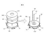
- FIG. 4 is a view showing the assembly of the lower yoke iron core.
- a stud fixing metal fitting 70 is fixed to the bottom portion of the lower metal fitting 30 by welding or the like, a stud 90 is arranged thereon, a stud 91 is also arranged at the center, and is fixed by tightening with a lock nut.
- the hollow disk-shaped laminated plate 171 is placed in the lower fastening bracket 30, the yoke core 160 is further placed thereon, and the laminated plate 172 is further placed on the yoke iron core 160. Place.
- the state where the yoke core 160 is placed is the right side of FIG.
- a coil support member 120 is attached to press and position the coil 100 around the center stud 91.
- two zero-phase core support fittings 80 connected to the zero-phase core receiver 81 of the metal frame that receives the zero-phase core 60 are attached, respectively. Tighten with a lock nut.
- the coil fasteners 120 for fixing the coil 100 are temporarily fixed to the outer peripheral surface of the six lower fasteners 30 and attached.
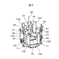
- FIG. 6A shows an external perspective view of the reactor device
- FIG. 6B shows a side view thereof.
- the fan-shaped magnetic leg iron core 140 is placed on the yoke iron core 160, and then the laminated plate 170 is placed on the magnetic leg iron core 140.
- the magnetic leg iron core 140 is mounted on the laminated board 170, and this is repeated, and in the figure, the five magnetic leg iron cores 140 are stacked, and the laminated board 170 is sandwiched and formed between the magnetic leg iron cores 140. .
- the inductance value (L value) of the reactor can be made variable by changing the thickness of the laminated plate 170, that is, the gap (gap) between the magnetic leg iron core 140 and the magnetic leg iron core 140.
- the inductance value (L value) can be adjusted.
- FIG. 7A shows an external perspective view of the reactor device
- FIG. 7B shows a side view thereof.
- the coil 100 has the same fan shape as that of the magnetic leg iron core 140, and the surface of the coil 100 is attached to the laminated plate 170 with an insulator (insulating paper) attached. It inserts into the magnetic leg iron core 140 piled up alternately from the upper part. Then, the position of the coil support member 150 is adjusted and fixed. Further, an insulating paper is inserted into the gaps between the coil 100 and the coil support member 120 and between the coil 100 and the magnetic leg iron core 140 so as not to be loose.
- insulator insulating paper
- FIG. 6 shows a process of inserting the coil 100 into each of the three magnetic leg iron cores 140, and insulating paper is used for the gap so that there is no backlash after the insertion.
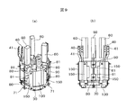
- FIG. 9A is an external perspective view in which the zero-phase core 60 is mounted
- FIG. 9B is a front view.
- the zero-phase iron core 60 is covered with an insulator (insulating paper), inserted into the zero-phase iron core receiver 81 formed of a metal frame from the upper side, and placed and fixed on the yoke iron core 160.
- the zero-phase core receiver 81 is formed with a notch in the vertical direction on the opposite side of the zero-phase core support bracket 80. There is no problem with the shape.
- the metal plate is made of a material such as SUS.
- the zero-phase iron core 60 is formed by stacking amorphous ribbons and cutting them into a rectangular shape to form a rectangular parallelepiped.
- a metal material such as a silicon steel plate can be used instead of the amorphous ribbon.
- a triangular insulator 154 is inserted into the center of the reactor device 10 from above and the coil support fitting 123 is inserted from above.
- the insulator 154 prevents dielectric breakdown or the like from occurring in order to secure an insulation distance between the tripod coils 100.
- the structure is a cylindrical body of a triangular prism, and wings that cover the end portions of the respective coils 100 are formed on the ridge line portions of the triangular prism.
- the structure of the coil support 123 is a triangular prism cylinder, and a wing portion that covers the end of the coil is formed on the ridge portion of the triangular prism.
- the structure is closed with a metal plate provided with After the insulator 154 and the coil support 123 are inserted and assembled, the stud 91 is fastened and fixed with a lock nut.
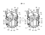
- FIG. 11 is an external perspective view showing a state where the upper yoke core is mounted.
- 161 is an upper yoke iron core
- 173 and 174 are laminated plates
- 20 is an upper clamp
- 70 is an upper stud fixing bracket.
- a laminated plate 173 is disposed between the magnetic leg iron core 140 and the yoke iron core 161, and the yoke iron core 161 is mounted on the laminated plate 173.
- the laminated plate 171 is placed on the upper surface of the yoke iron core 161, covered with the upper clamp 20 from above, and the hole formed in the stud fixing bracket 70 passes through the stud 90.
- the central hole 20 is positioned and incorporated so as to penetrate the stud 91. Then, the fastener 51 is attached to the stud 91 in the order of the laminate 173, the yoke core 161, the laminate 174, and the upper fastener 20. At this time, the side surface of the yoke iron core 161 is covered with an insulating paper so that there is no backlash at the time of attachment.
- FIG. 12 shows an external perspective view of the reactor 10 in a state where the eye nut 50 is attached and in a state where the assembling is completed.
- a magnetic leg iron core 140, a zero-phase iron core 60, and a yoke iron core 161 sandwiched between the lower fastener 30 and the upper fastener 20 by the fastener 51 are inserted into the stud 91 penetrating the central hole of the upper fastener 20. Tighten and fix.
- the coil support bracket 150 is attached to a bolt installed on the side surface of the upper clamp 20 and is fastened and fixed with a lock nut.
- the eye nut 50 is screwed and attached to the tip of the stud 91, an insulating tube is inserted into the line wires of the coil terminals 40 and 41 drawn from the coil 100, and the line wires are separated by a predetermined length or more.
- the inductance value (L value) of the U, V, and W phases of the reactor main body is confirmed to be a predetermined value using an LCR meter, and if it is different from the predetermined value, the magnetic leg shown in FIG. Returning to the process of assembling the iron core, the gap between the magnetic leg iron cores is adjusted.
- the above is description of the manufacturing method of the reactor at the time of employ
- FIG. 13 shows a perspective view of the iron core used by the reactor of the present invention.
- FIG. 13 (a) shows yoke iron cores 160 and 161
- FIG. 13 (b) shows a round magnetic leg iron core
- FIG. 13 (c) shows zero-phase iron. Show your heart.
- the difference from the second embodiment is that the magnetic leg iron core is round and has a slit at the center. That is, an amorphous ribbon is wound to form a cylindrical shape, cut along a line passing through the center, sandwiched with insulating paper, and bonded to form a slit 143.
- the yoke core shown in FIG. 13 (a) and the zero-phase core shown in FIG. 13 (c) are the same as those in the second embodiment, and thus the description thereof is omitted.
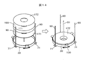
- a hollow disk-shaped laminated plate 170 is placed on the case of the lower clamp 30, a yoke core 160 is placed on the laminated plate 170, and an insulator (insulating sheet) 172 is further placed on the layer. Is placed.
- the laminated plate 170 is a sheet made of a material such as an epoxy resin. Further, the height of the case of the lower clamp 30 is the same as the height at which the laminated plate 170, the yoke core 160 and the insulator 172 are stacked.
- three studs 90 arranged on the outer periphery of the lower clamp 30 are provided with two zero-phase iron core support fittings 80 on each stud 90.
- the zero-phase core support fitting 80 is connected to and integrated with a zero-phase core receiver 81 formed of a rectangular metal frame that receives the rectangular parallelepiped zero-phase core 60.
- the zero-phase core 60 is inserted into the zero-phase core receiver 81 of the metal frame from above and placed on the insulating sheet of the laminated plate 172.
- the rectangular metal frame of the zero-phase core receiver 81 is formed with a notch in the surface on the center side so that the zero-phase core 60 can be easily inserted.
- FIG. 16 is a diagram illustrating a configuration in which a coil support bracket and an insulator are arranged in the center of the reactor device 10.
- reference numeral 125 denotes a coil support metal and 126 denotes an insulator.
- the shape of the coil support fitting 125 is an arc shape following the circular shape of the coil 101, and the three coil support fittings 125 are arranged around the center stud 91 and at equal intervals of 120 degrees between the zero-phase iron cores 60. Place and secure to stud 91.
- the insulator 126 is formed in an arc shape following the circular shape of the coil 101, and is arranged outside the three coil support brackets 125 to improve the insulating effect between the adjacent coils 101. . Further, an insulator such as silicon rubber is sandwiched between the coil support fitting 125 and the coil 101.
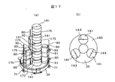
- FIG. 17A is a perspective view for assembling the magnetic leg iron core
- FIG. 17B is a diagram showing the arrangement relationship between the yoke iron core 160 and the magnetic leg iron core 141.
- the magnetic leg iron core 141 is disposed between the zero-phase iron cores 60 and placed on the insulator (insulating sheet) 172 on the yoke iron core 60.
- the laminated board 175 is mounted on the magnetic leg iron core 141, Furthermore, the magnetic leg iron core 141 is mounted on a layer, This is repeated and the magnetic leg iron core 141 is piled up and assembled. In the figure, five magnetic leg iron cores 141 are stacked.
- the arrangement relationship between the magnetic leg iron core 141 and the yoke iron core 160 is such that the diameter length of the magnetic leg iron core 141, the radius of the hole inside the yoke iron core 160, and the talk iron core 160
- the circular magnetic leg iron core 141 is formed so as to be inscribed in the inner hole of the yoke iron core 160 and inscribed in the outer circumferential circle of the yoke iron core 160.
- the linear direction of the slit 143 formed in the magnetic leg iron core 141 is set to be parallel to the winding direction of the yoke iron core 160 wound in a toroidal shape.
- the line of the slit 143 of the magnetic leg iron core 141 is arranged in the tangential direction of the winding of the yoke iron core 160 wound in a toroidal shape.
- the inductance value (L value) of the reactor device 10 is adjusted by changing the thickness of the laminated plate 175 sandwiched between the magnetic leg iron cores 141, that is, the gap (Gap) between the magnetic leg iron cores 141.
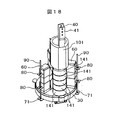
- the coil 101 is vertically inserted into the circular magnetic leg iron core 141 stacked on the yoke iron core 160 from above. Further, an insulator is inserted into the gap between the inner diameter of the coil 101 and the outer diameter of the magnetic leg iron core 141, and adjustment is made so that there is no backlash. Further, in the terminals 40 and 41 of the coil 101, the inner coil terminal 40 is drawn from the inner peripheral side of the coil, the outer coil terminal 41 is drawn from the outer peripheral side of the coil 101, and the outer coil terminal 41 has a stepped shape. Bending (one step) is provided to increase the distance from the inner coil terminal 40.
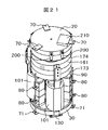
- FIG. 19 shows a perspective view of a state in which the three-leg coil 101 is inserted into the magnetic leg iron core 141.
- FIG. 19 shows a state in which the magnetic leg iron core 141 and the coil 101 are fixed by repeating the process of stacking the magnetic leg iron core 141 shown in FIG. 17 and the process of inserting the coil 101 shown in FIG. 18 into the magnetic leg iron core 141. .
- the heights of the three zero-phase cores 60 and the magnetic leg cores 141 arranged therebetween are set to be substantially the same.
- reference numeral 158 denotes an insulator
- 127 denotes a coil support bracket
- the insulator 158 has an arc shape that follows the circular shape of the coil 101, is formed so as to cover the coil 101, and insulates between adjacent coils. Has the effect of earning distance.
- the coil support 127 is a substantially triangular metal plate, and connects a metal plate having an arc shape that follows the circular shape of the coil 101 perpendicular to the side of the triangular plate. Then, after the insulator 158 is attached, the coil support 127 is inserted and attached from above. Then, the stud 91 is passed through the hole formed in the center of the coil support metal 127 and is fastened and fixed with a lock nut.
- a laminated plate 173 is placed on a configuration in which a zero-phase iron core 60, a magnetic leg iron core 141 and a coil 101 are incorporated, a yoke iron core 161 is placed thereon, and a laminated plate 174 is placed thereon. Place. Then, the laminated plate 173, the yoke iron core 161, and the laminated plate 174 are covered with a case of the upper fastener 20. Further, a stud fixing metal fitting 70 is fixed to the outer periphery of the upper surface of the upper fastening metal 20 by welding or the like.
- a stud fixing metal fitting 70 formed on the outer periphery of the upper fastener 20 is a rectangular metal plate, and a hole is formed in a portion protruding from the upper fastener 20, and the stud 90 is passed through this hole at three locations.
- the stud 90 is tightened and fixed with a lock nut.
- a hole is formed in the center of the upper fastening member 20, the stud 91 is passed through the hole, and the lower fastening member 30 is fastened with a lock nut using the fastening member 51 to fix the entire reactor.
- the eye nut 50 for hanging a reactor main body is attached to the front-end
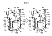
- the coil 101 is configured such that two coil retainers 200 disposed on the side surface of the upper fastener 20 are disposed with respect to one leg of the coil, and both sides of the coil terminals 40 and 41 are retained.
- Reference numeral 210 denotes a name plate, which displays the product name, model, serial number, manufacturing date, manufacturer name, and the like of the apparatus.
- FIG. 23 shows a configuration in which casters 201 are installed on the base 130 at the bottom of the reactor device 10.
- casters 201 are attached to U-shaped bases 130 arranged at equal intervals at three locations on the circumference of the bottom of the lower clamp 30 so that the reactor device 10 can move smoothly, and round magnetic legs
- the assembly process of the reactor device on which the iron core 141 is mounted is completed.
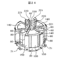
- FIG. 24 shows a configuration in which the coil 100 is inserted and arranged around the fan-shaped magnetic leg iron core 140, and the zero-phase iron core 60 is arranged between the coils 100.
- the coil terminals 220 and 221 are arranged from the center of the reactor device. The perspective view which pulled out upwards is shown.
- FIG. 24 a configuration in which plate-like coil terminals 220 and 221 each having a hole at the start and end of winding of the coil are connected to the inside of the coil 100 arranged around the three legged magnetic cores 140. To do.
- the central hole of the yoke iron core 161 is insulated so as not to contact the coil terminal 221. Further, the central portion of the upper fastener 20 is configured to have a hole for the coil terminals 220 and 221 to protrude.
- FIG. 25 is a perspective view in which the sound absorbing material 400 is disposed between the lower fastener 30 and the laminated plate 171.
- the yoke core 160 is sandwiched between the laminated plate 170 and the laminated plate 172, and the sound absorbing material 400 is disposed between the lower laminated plate 170 and the lower fastener 30 to absorb sound.
- the cause of sound in the reactor device is that an inverter is mounted on the power controller system, so that various frequency components are generated in the power, and the magnetic leg iron core, the yoke iron core, etc. vibrate and appear as sound.
- a sound absorbing material is used to absorb these sounds. Examples of the sound absorbing material include porous materials, that is, fibrous glass wool having a large number of small holes, sponge-like urethane, and the like.
- the sound absorbing material 400 is disposed between the laminated plate 170 and the lower metal fitting 30, but the upper and lower yoke cores, the upper and lower yoke cores, the three magnetic leg iron cores and the coils, and the three The entire zero-phase iron core may be covered with a sound absorbing material.
- Example 6 Next, a method of assembling using a round magnetic leg iron core will be described. A major difference from the round magnetic leg iron core described in the third embodiment is that no zero-phase iron core is attached.
- mounting of the lower yoke core will be described with reference to FIG. 26A.
- studs 90 and 91 are arranged at one place in the center of the bottom fastening metal 30 of the circular case, three places on the outer periphery, and perpendicular to the bottom surface of the bottom fastening metal 30.
- the three studs 90 arranged on the outer circumference are arranged at intervals of 120 ° and arranged on the outer circumference of the fixed stud fixing metal 71, and the center stud 91 is arranged on the center of the lower fastening metal 30 and the lock nut. Tighten and fix with.
- a laminated plate 171 such as a hollow disc-shaped silicone rubber is disposed in the case of the lower fastener 30.
- a hollow donut-shaped yoke iron core 160 is placed on the laminated plate 171, and a hollow insulator (insulating sheet) 172 is placed thereon, and the magnetic material placed on the yoke iron core 160. Insulate the leg iron core.
- the laminated plate 170 uses a sheet of silicone rubber or epoxy resin.
- the height of the case of the lower metal fitting 30 is substantially the same as the height at which the laminated plate 171, the yoke core 160 and the insulator 172 are stacked.
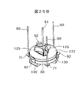
- FIG. 26B shows a configuration in which the coil support fitting 125 and the insulator are arranged in the center of the lower fastening fitting 20.
- reference numeral 125 denotes a coil support fitting, which covers the surface with an insulator to insulate the coils.
- the shape of the coil support fitting 125 is an arc shape following the shape of the coil 101, and the three coil support fittings 125 are arranged around the center stud 91 at equal intervals of 120 °, and the stud 91 or the laminated plate 172. It is fixed to.
- the insulator covering the coil support fitting 125 is shaped like an arc following the shape of the coil support fitting 125 to improve the insulation effect between the adjacent coils 101. Silicone rubber or the like is used as the insulator.
- FIG. 26C shows a perspective view for assembling the columnar magnetic leg iron core 141
- FIG. 26C (b) shows the relationship between the arrangement of the columnar magnetic leg iron core and the yoke iron core.
- the columnar magnetic leg iron core 141 is placed on the insulating sheet 172 on the yoke iron core 160.
- the columnar magnetic leg iron cores 141 are stacked in four stages, and a laminated plate 175 is inserted between the magnetic leg iron cores 141 and stacked. This configuration is arranged at three positions at 120 ° intervals at corresponding positions of the coil support bracket 125.
- the arrangement relationship between the columnar magnetic leg iron core 141 and the yoke iron core 160 is as follows: the diameter length of the magnetic leg iron core 141 and the radius length of the hole 162 inside the yoke iron core 160. The sum is formed so as to be equal to the radius length of the yoke core, and the magnetic leg core 141 having a circular cross section is circumscribed in the hole 162 inside the yoke core 160 and is inscribed in the outer periphery of the yoke core 160. To do.
- the line of the slit 143 formed in the circular magnetic leg iron core 141 is formed to be parallel to the winding direction of the yoke iron core 160 wound in a toroidal shape.
- the inductance value (L value) of the reactor device is determined by the thickness of the laminated plate 175 sandwiched between the magnetic leg iron cores 141, that is, the gap between the magnetic leg iron cores 141, and the L value can be adjusted by changing this gap. .
- FIG. 26D a coil mounting method for inserting a coil into the stacked cylindrical magnetic cores 141 will be described with reference to FIG. 26D.
- the coil 101 is inserted into the magnetic leg iron core 141 stacked on the yoke iron core 160 vertically from above until reaching the insulating plate 172 and fixed. Further, an insulator is inserted in the gap between the inner peripheral side of the coil 101 and the outer peripheral side of the magnetic leg iron core 141, and adjustment is made so that there is no backlash.
- the inner terminal 42 is drawn from the inner peripheral side of the coil 101
- the outer terminal 43 is drawn from the outer peripheral side of the coil.
- the portion where the terminal comes out of the coil is provided with a step so as to increase the separation distance. Further, when the coil is inserted into the magnetic leg iron core 141 and mounted, the coil 101 is positioned so as to contact the coil support fitting 125. In this way, the coils 101 are accurately arranged at equal intervals of 120 °.
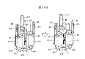
- FIG. 26E shows a configuration in which the coil 101 is inserted into each of the three magnetic leg iron cores 141 and mounted on the support bracket 92, and the configuration in which the coil is fixed by the coil support bracket 125 is shown in the right figure. .
- the coil fixing fitting 127 is disposed at the center.
- the coil fixture 127 is formed of a triangular metal plate, and has a hole in the center, and is inserted into the center stud 91 and arranged.
- arc-shaped members following the outer shape of the coil 101 similar to the coil support fitting 125 are arranged at equal intervals of 120 °, and the arc-shaped member covers an insulating sheet. The insulation between the coils is enhanced.
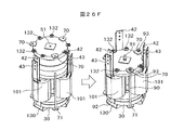
- FIG. 26F a laminated plate 173 is placed on a configuration incorporating a three-legged magnetic leg iron core 141 and a coil 101, a yoke iron core 161 is placed thereon, and a laminated plate 174 is further placed thereon. To do. Then, the laminated plate 173, the yoke iron core 161 and the laminated plate 174 thereon are covered with the case of the upper fastener 20.
- a rectangular metal plate stud fixing bracket 70 is formed with a hole in a portion protruding from the outer periphery of the upper clamp 20, a stud 90 is passed through the hole, and the stud 90 is fastened and fixed with a lock nut 93. .
- the coil presser bracket receiver 132 is also a rectangular metal plate, and a hole is provided in a portion protruding from the outer periphery of the upper clamp metal 20 so as to pass through the bar portion of the coil presser bracket 134. It is tightened and fixed.
- a fastener 51 formed of a rectangular metal plate is disposed in the center of the upper fastener 20, and a hole is disposed in the center of the fastener 51 so that the stud 91 can be penetrated. The fastener 51 is fastened and fixed by a lock nut 95 after the stud 91 is inserted.
- the eye nut 50 is attached to the upper part of the stud 91 at the center of the upper fastener 20 so that the reactor body can be suspended.
- the coil holding metal fitting 134 has a round bar-shaped tip having a circular shape larger than the diameter of the bar, and has an area enough to hold a part of the coil. Is pressed against the lower clamp 30 to fix it.
- the terminals 42 and 43 are provided with a plurality of holes 45 so that power lines can be connected.
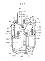
- FIG. 26I shows an external perspective view of a reactor device in which all parts are mounted and a magnetic leg core having a round cross section is mounted, a front view thereof is shown in FIG. 26H, and a top view thereof is shown in FIG. 26G.
- the coil 101 is placed on a coil support metal fitting 92 disposed around the lower metal fitting 30 and is a coil holding metal fitting 134 having a disc connected to the tip with a metal rod.
- the other side of the metal rod that is pressed down is received by a coil support fitting receiver 132 disposed around the upper fastening fitting 20 and is fastened and fixed by a lock nut 133.
- the coil 101 is fixed at two locations on both sides of the terminal plates 42 and 43 with respect to one leg coil.
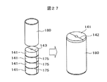
- FIG. 27 shows a state in which the insulator cylindrical body 180 is inserted from above in a state where the magnetic cores 141 having a round cross section with the slits 143 are stacked in four layers with the insulator laminate 175 interposed therebetween.
- the perspective view of the structure of the incorporated magnetic leg iron core is shown.
- the magnetic leg iron cores covered with the cylindrical body 180 of the insulator shown in FIG. 27 are arranged on the yoke iron core 160 at equal intervals of three legs 120 °, and the coil 101 is inserted as shown in FIG. 26E. Form.
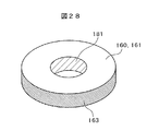
- FIG. 28 is a perspective view of the donut-shaped yoke cores 160 and 161 having a circular hole in the center.
- the yoke iron core is constructed by mounting a circular metal plate reinforcement bracket 181 on the circumferential surface of the inner hole, and the thickness of the metal plate reinforcement bracket is 2 mm or more. If the inside of the central hole of the yoke core is not reinforced, the circular shape of the hole portion may be distorted, and stress on the iron core is applied. And when the stress of an iron core is applied, the iron loss of a yoke iron core will become large and will worsen. Therefore, by reinforcing the inner peripheral surface of the hole inside the yoke iron core, it is possible to prevent a shape change due to distortion.
- the insulator 163 is wound around the outermost peripheral surfaces of the yoke cores 160 and 161.
- the insulator 163 uses an insulating sheet and winds the outer periphery of the yoke core.
- the outer peripheral surface which is the side surface of the yoke cores 160 and 161
- the insulating sheet 163 no abnormal current is generated between the yoke core and the upper or lower fastener.
- the creepage distance between the yoke core and the upper or lower fastener can be increased, the floating loss can be reduced, and the characteristics are not deteriorated. Further, it also has a function of eliminating play between the yoke iron core and the upper or lower fastener.
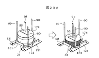
- FIG. 29A shows an assembly drawing for mounting the lower yoke iron core.
- 29A, 31 is a lower clamp
- 131 is a base
- 90 and 91 are studs
- 173 is a laminated plate
- 161 is a lower yoke iron core
- 174 is a laminated plate
- 55 is a magnetic leg iron core positioning laminated plate
- 163 is a yoke.
- the lower metal fitting 31 is a substantially hexagonal shape, has a case shape with a fold-back part, a stud 91 is vertically arranged at the center part, and the center of the outer peripheral region of the arrangement position of the yoke core, not the fold part.
- the studs 90 are vertically arranged at three equal intervals of 120 °.
- the base 131 is L-shaped to increase the strength, and two L-shaped sides are arranged on the bottom surface of the lower fastening bracket 31 and fixed by welding or the like to stabilize the reactor device.
- the positional relationship between the lower fastening bracket 31 and the two bases 131 is such that the base 131 is parallel and is perpendicular to the two sides of the lower fastening bracket 31.
- a laminated plate 173 made of an insulating sheet is placed on the lower clamp 31, a hollow donut-shaped yoke iron core 161 is placed on the laminated plate 173, and the laminated plate is placed on the yoke iron core 161.
- 174 is placed.
- an iron core positioning laminated plate core of equilateral triangular magnetic leg iron cores is arranged on the laminated plate 174.
- the iron core positioning laminate 55 is arranged with a hole at the center (middle point) of the equilateral triangle and through the center stud 91, the direction of which is one of the equilateral triangles as shown in FIG. 2B (b).
- the perpendicular lines drawn from the corners and the longitudinal lines of the two bases fixed to the lower clamp 31 are arranged in parallel.
- the side surface of the yoke iron core 161 is formed by winding the insulating sheet 163 so that there is no backlash.
- FIG. 29B shows an external perspective view of the step of attaching the magnetic leg iron core
- FIG. 29B (b) shows a top view of FIG. 29B (a).
- the magnetic leg iron core 142 has a substantially fan shape.
- the magnetic leg iron core 142 is manufactured by stacking strip-shaped iron core materials cut into a predetermined thickness and length. The magnetic leg iron core 142 is placed on the laminated plate 174 on the yoke iron core 161.
- the central portion of the fan-shaped magnetic leg iron core 142 is cut to form a flat portion, and this flat portion is disposed in contact with one side of the equilateral triangle-shaped iron core positioning laminate as shown in FIG. 29B (b). To do.
- the positioning of the magnetic leg iron core can be accurately arranged.
- Both fan-shaped wing portions of the magnetic leg core 142 are cut, and the arc-shaped portion cuts the arc-shaped portion into three equal parts by cutting the arc-shaped part into approximately three equal parts. Then, a substantially octagonal deformed fan-shaped magnetic leg iron core 142 is formed.
- the magnetic leg iron cores 142 are stacked in four stages, and a laminated plate 175 is sandwiched between the magnetic leg iron cores 142.
- the shape including the coil depends on the shape of the iron core. Therefore, in the case where the magnetic leg iron core has an approximately octagonal deformed fan shape as described above, the outermost outer shape of the magnetic leg iron core can be reduced, and inevitably the outermost outer diameter of the coil can be reduced. The size of the final reactor in the radial direction can be reduced. Such a reactor is effective when there is an installation place such as a panel or there is a dimension limitation.
- the coil fasteners 151 are arranged on the three studs 90 arranged on the outer periphery of the circular laminated plate 174.
- the coil fastener 151 is a long and narrow metal plate with a screw hole in the center, cut and attached to the stud 90, and the back side of the coil fastener 151 is tightened with a lock nut at a predetermined height, that is, a height that supports the coil. , Fix.
- the heights of the three coil fasteners 151 are substantially the same.
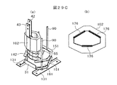
- FIG. 29C shows an external perspective view for mounting the coil
- FIG. 2C (b) shows a cross-sectional view of the coil.
- the coil 102 is vertically inserted and attached to the magnetic leg iron core in a state where four individual magnetic leg iron cores 142 are stacked. Further, terminals 42 and 43 are arranged on the upper side of the coil 102 so that it can be connected to the power supply line.
- terminals 42 and 43 are arranged on the upper side of the coil 102 so that it can be connected to the power supply line.
- the shape of the hole inside the coil 102 is the same as the outer shape of the magnetic leg iron core 142, and is slightly enlarged so that the hole of the coil 102 can be inserted. Also, three insulating boards 176 are arranged inside the coil 102, and there is a gap between the magnetic leg iron core 142 and the coil 102. If there is play, adjustment is made with the insulation board 176 and no play occurs. Like that.
- FIG. 29D shows an external perspective view in which the mounting of the one leg magnetic core and the coil of FIG. 29C (a) is repeated, and the right leg of FIG.
- positions the iron core positioning laminated board 55 from the upper part of the mounted coil 102 is shown.
- a single leg magnetic core 142 is formed by stacking four layers with the laminated plate 175 sandwiched between the iron cores, and the process of inserting and attaching the coil from above the magnetic leg core is also performed for the other two poles. As shown, complete all three legs and complete the installation of the magnetic leg core and coil.
- the core positioning laminated plate 55 is arranged by attaching a screw hole arranged at the center of the equilateral triangular core positioning laminated plate 55 to the stud 91, and the position of the iron core is adjusted.
- the magnetic leg iron core 142 is slightly higher than the coil 102. 2D, when the coil 102 is positioned with high accuracy, the coil fastener 151 is attached to the outer stud 90 with screws, and the coil 102 is connected to the lower coil fastener 151 and the upper coil fastener 151. Tighten and fix with lock nut. The coil 102 is fixed on each of the three legs.
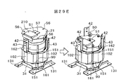
- FIG. 29E shows an external perspective view in which a yoke iron core is placed on the upper side of the tripod coil 102 and fixed with an upper clamp.
- a circular hollow laminated plate 177 is disposed on the tripod coil 102, and the yoke iron core 162 is placed thereon.
- the yoke iron core 162 has the same circular shape as the lower yoke iron core 161 and has a hollow donut shape.
- a circular and hollow laminated plate 178 is placed on the circular yoke core 162.
- the periphery of the yoke core 162 is wound with an insulating sheet to insulate it from surrounding components.
- the laminated plates 177 and 178 and the yoke iron core 162 are covered with the case of the upper fastener 21, the stud 91 is passed through the hole 57 for the center stud 91 arranged at the center of the upper fastener 21, and the upper fastener 21
- the studs 90 are passed through the three stud holes 56 arranged around and are fastened with lock nuts to fix the magnetic leg iron core, the coil and the yoke iron core.
- An eye nut 50 is provided at the tip of the central stud 91 so that the reactor device can be suspended.
- Reference numeral 210 denotes a name plate, which stamps the name, model, serial number, date of manufacture, and manufacturer of the apparatus.
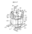
- FIG. 29F shows an external perspective view of a reactor device in which all the components are mounted and a magnetic leg iron core having a cross section is mounted, a front view thereof is shown in FIG. 29H, and a top view thereof is shown in FIG. 29G.
- two L-shaped bases 131 are fixed to the lower clamp 31 by welding or the like, and the yoke iron core 161 and the laminated plate 174 are housed in the case of the lower clamp 31.
- 31 has a deformed hexagonal shape cut at a predetermined length from three apexes of an equilateral triangle. That is, in FIG.
- the coil 102 is arranged inside the bent side, and the coil 012 is arranged so that the magnetic leg iron core and the yoke iron core in the coil 102 overlap each other. Then, output terminals 42 and 43 are provided vertically from the inside and outside of the coil 102 so that they can be connected to external terminals.
- the coil 102 is fastened with two upper and lower lock nuts sandwiching a part of the coil 102 with two coil fasteners 151 arranged on the stud 90. Further, the lower metal fitting 31 and the upper metal fitting 21 are lock nuts 96 attached to three outer peripheral studs 90 and one central stud 91, and the yoke iron cores 161 and 162, the coil 102 and the magnetic leg iron core 142 are connected. It is tightened and fixed.
- FIG. 30A shows a plan view when the coil fixing bracket 190 is mounted
- FIG. 30B shows an external view of the coil fixing bracket.
- the coil fixing bracket 190 extends a metal plate having a predetermined width radially from the center in three directions, and extends the metal plate from the center of the reactor to the nearest portion of the magnetic leg iron core 142 and the coil 102.
- each of which is L-shaped to form a claw portion 192 to be inserted and fixed in the gap between the magnetic leg iron core 142 and the coil 102 To do.
- the angles in the three directions are equally spaced at 120 °, and a hole 191 for attaching to the stud 91 disposed at the center of the reactor is provided at the center of the coil fixing bracket 190.
- FIG. 30A shows a plan view in which the coil 102 with the magnetic leg iron core 142 mounted on the coil fixing bracket 190 shown in FIG. 30B is arranged, and the hole 191 at the center of the coil fixing bracket 190 is studded. 91, and the protruding claws 192 of the coil fixing metal fitting 190 are inserted into the gaps between the magnetic leg iron cores 142 and the coils 102, and are fastened and fixed by the lock nuts of the studs 91.
- the coil 102 can be prevented from being displaced radially from the center, that is, radially.
- the coil fixing metal 190 since the coil fixing metal 190 is in contact with the coil 102 and the magnetic leg iron core 142, there is also an effect of radiating heat generated in the coil 102 and the magnetic leg iron core 142, and the heat radiation effect of the entire reactor device is improved.
- Example 11 a coil fixing method according to Example 11 of the present invention will be described with reference to FIG.
- a band 205 is wound around a three-leg coil 102 and three studs 90, and the coil 102 is fastened and fixed by the band 205.
- the band 205 is not limited to a single layer, and may be double or more.
- the band 205 is made of a stainless steel plate or a twisted metal wire.
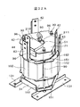
- FIG. 32A has the same configuration as the external view of the reactor device shown in FIG. 29F, but the difference is that a vent hole 211 is arranged in the center of the upper fastener 21.
- FIG. 32A the description of the part common to FIG. 29F is omitted, and the part of a different air hole 211 will be described.
- a vent hole 211 is arranged near the center of the upper fastening member 21 at the top of the reactor device, and the vent hole 211 is formed by a mesh or a punching hole and is formed within the range of the hole inside the yoke core 162.
- the vent hole 211 is disposed within the range of the inner hole of the yoke core 161 in the vicinity of the center of the lower clamp 31 of the lower side of the reactor device, the air flow is generated at the center of the reactor device.
- the reactor flows from the bottom to the top of the reactor device, takes away heat generated from the magnetic leg iron core 142 and the coil 102, and exhausts it to the outside for cooling.
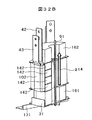
- FIG. 32B shows a longitudinal sectional view at the center of the reactor device 10, in which 91 is a center stud, 161 is a lower yoke core, 142 is a magnetic leg core, 102 is a coil, 162 is an upper yoke core, Reference numeral 214 denotes an air flow.
- the periphery of the center stud 91 has a space
- the vent hole 211 is disposed in the central axis direction of the lower lower clamp 31 and the upper clamp 21 on the upper side
- air 214 flows from the lower side to the upper side, the magnetic leg iron core 142 and the coil 102 are cooled, and heat does not accumulate inside. Since the outer periphery of the coil portion of the reactor device is in contact with the outside air, it is radiated to the atmosphere.
- FIG. 32C shows a cross-sectional view of the coil portion of the reactor device.
- a gap 213 is formed between adjacent coils 102, so that air from the outside of the reactor device is between the coils 102. It flows into the center from the gap 213 (arrow 212) and flows out from below the reactor device or upward from the center. There is also air that flows out from the gap 213 between the coils 102.
- the coil 102 and the magnetic leg iron core 142 can be cooled, and the cooling efficiency is improved.
- the cooling structure of the present invention for cooling the coil periphery is effective.
- FIG. 33 is a perspective view of the reactor device in which a fan 215 is arranged in the center of the upper fastening bracket 21 on the upper side of the reactor device.
- the cooling fan 215 is configured to be installed above the vent hole 211 shown in FIG. 32A. In this way, in the configuration shown in FIGS. 32A to 32C, since the fan 215 is installed in the vent hole 211 near the center of the upper fastener 21, the air is adjacent to the vent hole 211 in the center of the lower fastener 31 or adjacent thereto.
- the air is forcibly sucked from the gap 213 of the coil 102, exhausted from the center of the upper fastener 21, and cooled.
- the fan 215 is installed at the center of the upper upper clamp 21.
- a fan is also installed in the central air hole 211 of the lower lower clamp 31 to force external air. You may make it the structure sucked in.
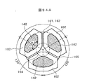
- FIG. 34A is a plan view showing the arrangement positions of the magnetic leg iron core, the coil, and the yoke iron core.
- the magnetic leg cores 142 when the yoke cores 161 and 162 are circular in the shape of a donut with a hole in the center, the magnetic leg cores 142 having the same shape are arranged at equal intervals of 120 ° in order to make the three-phase inductance values uniform.
- the cross-sectional area refers to the area where the cross-sectional area of the magnetic leg core overlaps the end surface of the yoke core in consideration of the flow of magnetic flux to the yoke core.
- the shape of the magnetic leg cores arranged at intervals of 120 ° ⁇ 10 ° is shown in FIG. 34A, and the apex angle on the inner peripheral side of the magnetic leg iron core is set to 120 ° ⁇ 10 °.
- the magnetic leg iron core portion inside the inner circle 164 inside the yoke iron cores 161 and 162 that is, the non-overlapping portion between the iron cores becomes an unnecessary portion because the magnetic flux does not flow, and is chamfered in an arc shape or a straight line.
- 34B shows the positional relationship between the magnetic leg iron core 142 and the yoke iron cores 161 and 162.
- the fan-shaped outer periphery is chamfered into an arc 302, and the fan-shaped Since the apex angle (center) portion does not overlap with the yoke iron cores 161 and 162, the arc shape 302 is chamfered following the inner circle 164 inside the yoke iron core as an unnecessary portion. Further, this arc-shaped portion may be chamfered in a straight line. 34B, the outer periphery of the magnetic leg iron core 142 may be aligned with the string 301 along the outer circle 165 of the yoke iron cores 161 and 162. Here, the arc shape is aligned with three strings 301. Furthermore, the fan-shaped both ends are cut so that the tip is not sharpened.
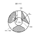
- the cross-sectional area of the magnetic leg iron core 142 will be described.
- the minimum cross-sectional area as in the upper right magnetic leg iron core 142 in FIG. 34C is when the fan-shaped arc-shaped outer periphery is one string 301. Therefore, the cross-sectional area of the magnetic leg iron core 142 needs to be larger than this.
- the apex angle of the fan-shaped center is 120 ° ⁇ 10 °, and from the vertex of the fan-shaped center to the inner circle 164 of the hole inside the yoke iron cores 161 and 162.
- the distance from the top of the fan-shaped center to the outer circle 165 of the yoke core (pointing to the outermost circle) is R2, and the cross-sectional area of the magnetic leg core 142 that is inside the inner circle 164 of the yoke core is R2.
- Is S1 and the cross-sectional area of the magnetic leg core 142 overlapping the yoke core is S2, It becomes. Therefore, a magnetic leg iron core having a shape expressed in such a region of S 2 -S 1 may be used.
- the reactor device may require different outer shapes depending on the environment of the installation location, but if such a shape having a minimum cross-sectional area satisfies the required outer shape, this shape is good. .
- the apex angle is an acute angle with the shape of the magnetic leg iron core, partial discharge occurs when energized, so that the dimension between the magnetic leg iron core 142 and the coil 102 is unnecessarily widened, and the weight of the entire reactor. And an increase in volume. For this reason, if the two apex angles on the outer peripheral side are chamfered from the shape shown in the region of S 2 -S 1 and all apex angles are 90 ° or more, an increase in the weight and volume of the entire reactor is suppressed. can do.
- the magnetic leg iron core 142 installed at 120 ° ⁇ 10 ° needs to be fastened with three legs with equal stress.
- studs 90 for fastening the magnetic leg iron core are arranged at intervals of 120 ° ⁇ 10 ° around the yoke iron core, and the magnetic leg iron core, coil and yoke iron core between the upper fastener 21 and the lower fastener 31 are attached.
- the stud 90 and the stud 91 are tightened and fixed.
- the magnetic leg iron core positioning laminate 55 has an equilateral triangle shape, and a hole for the center stud 91 is arranged at the midpoint of the equilateral triangle. And it forms so that the arc-shaped part or linear part inside a tripod magnetic leg iron core may contact
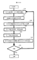
- Example 14 Setting of the magnetic leg iron core, coil, and yoke iron core will be described with reference to the flowchart shown in FIG. 35A and FIG. 35B.
- the coil thickness of the coil material and the number of turns of the coil are determined, and the thickness of the coil is determined (S10).
- the thickness of the coil material is determined in consideration of loss, and the number of turns is determined in consideration of the inductance value.
- the cross-sectional shape of the magnetic leg iron core is determined (S20). That is, the cross-sectional area is determined by calculating backward from the number of turns of the coil and the designed magnetic flux density, and the shape of the magnetic leg core is determined within the cross-sectional area.
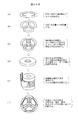
- the shape of the magnetic leg iron core has a fan shape, a circular shape, etc., and is determined by the mass, the overall shape and characteristics (FIG. 35B (a)).
- magnetic cores and coils for three phases are arranged on the circumference at equal intervals of 120 ° (S30) (FIG. 35B (b)).
- the inner diameter of the hole inside the yoke core and the outer diameter of the yoke core are determined (S40).
- step S30 the positional relationship between the magnetic pole core and the coil is confirmed, and the inner diameter and outermost outer diameter of the yoke core are determined so that the magnetic leg core and the yoke core overlap (FIG. 35B (c)).
- the width of the yoke core is determined (S50). That is, the width of the yoke core (difference between the outer diameter and the inner diameter) is determined by calculating backward from the magnetic flux density of the designed coil and the thickness (height) of the yoke core stack (FIG. 35B (d)). Next, the thickness (height) of the coil and the GAP dimension between the magnetic leg cores are determined (S60) (FIG. 35B (e)). As described above, the necessary dimensions of the coil, magnetic leg iron core and yoke iron core are determined, and these values are determined for the dimensions of each part of the reactor device, the engagement with the stud, the temperature, the characteristics of the reactor device, etc. (S70) ( FIG. 35B (f)). If the determination result is yes, the design ends, and if no, the process returns to step S10 to repeat this flow.
- Reactor device 20 21 Upper clamp 30, 31 Lower clamp 40, 41, 42, 43 Coil terminal 50 Eye nut 51 Fastener central clamp 55 Magnetic leg core positioning laminate 56 Stud hole 60... Zero-phase iron core 70, 71. Stud fixing bracket 80.
- Laminated plate 180 Insulator cylindrical body 181.
Landscapes
- Engineering & Computer Science (AREA)
- Power Engineering (AREA)
- Manufacturing Cores, Coils, And Magnets (AREA)
Abstract
Description
(実施例1)
本発明のリアクトル装置の基本的な構造について図1を用いて説明する。
図1は、リアクトル装置の基本的な構造を示す斜視図で、図1において、160、161はヨーク鉄心、140は磁脚鉄心、100はコイル、60は零相鉄心である。ヨーク鉄心160、161は、アモルファス薄帯をトロイダル状(円環状)に巻いて形成し、中空を有する円形の厚みを備えた形状である。
次に、本発明のリアクトル装置の製造方法について説明する。扇形状の磁脚鉄心140を用いた場合のリアクトル装置の製造方法を図3~図12に示す。図3において、図3(a)は、リアクトル10の上下に配置し、磁脚鉄心140と零相鉄心60を挟むように構成するヨーク鉄心160、161の斜視図を示す。図3(a)のヨーク鉄心は、同心円となっているが、実際はアモルファス薄帯をトロイダル状に巻いた中心が孔を有する円柱形状である。また、図3(b)は、磁脚鉄心140の外観斜視図を示し、アモルファス薄帯をトロイダル状に巻いた鉄心を軸方向に切断して扇形状の鉄心としている。図3(c)は、零相鉄心60の外観斜視図で、細長い矩形のアモルファス薄帯を積層して、直方体を形成したものである。
図10において、コイル100をコイル支え金具150で固定した状態で、上方より三角形状の絶縁物154をリアクトル装置10の中心部に差し込み、その上からコイル支え金具123を差し込む。絶縁物154は、3脚のコイル100間の絶縁距離を確保する目的で、絶縁破壊などが生じるのを防止する。そしてその構造は三角柱の筒体形状で、三角柱の稜線部にはそれぞれのコイル100の端部を覆う翼部を形成する。また、コイル支え金具123の構造は、三角柱の筒体形状とし、三角柱の稜線部にはコイルの端部を覆う翼部を形成し、三角柱の筒体上部は、中央にスタッド91が貫通する孔を設けた金属板で塞いだ構造とする。絶縁物154及びコイル支え金具123を差し込んで、組み立てた後スタッド91をロックナットにて締め付け固定する。
次に、本発明の第3の実施の形態のリアクトル相に製造方法について説明する。図13は、本発明のリアクトルの用いる鉄心の斜視図を示し、図13(a)はヨーク鉄心160、161、図13(b)は丸形の磁脚鉄心、図13(c)は零相鉄心を示す。図13において、実施例2と異なるのは、磁脚鉄心が丸形で、中央にスリットを形成している点である。すなわち、アモルファス薄帯を巻いて円柱形を形成し、中心を通る線で切断して絶縁紙を挟み、接着してスリット143を形成する。また、図13(a)に示したヨーク鉄心及び図13(c)に示した零相鉄心は、実施例2と同じであるため、説明を省略する。
次に、本発明のリアクトル装置において、3脚のコイル端子をリアクトルの中央から引き出す構成について、図24を用いて説明する。図24は、扇形状の磁脚鉄心140の周囲にコイル100を差し込んで配置し、そのコイル100の間に零相鉄心60を配置した構成を示し、リアクトル装置の中央部からコイル端子220、221を上方に引き出した斜視図を示す。図24において、3脚の磁脚鉄心140の周囲に配置しているコイル100の内側に、コイルの巻始め及び巻終わりにそれぞれ孔を有した板状のコイル端子220、221を接続する構成とする。また、図示していないが、ヨーク鉄心161の中央の孔は、コイル端子221と接触しないように絶縁を施す。さらに、上締め金具20の中央部は、コイル端子220、221が突き出るため孔を設ける構成とする。
次に、上下締め金具と積層板の間に吸音材400を配置する構成について、図25を用いて説明する。図25は、下締め金具30と積層板171の間に吸音材400を配置する斜視図を示す。図25において、ヨーク鉄心160を積層板170及び積層板172で挟み、下側の積層板170と下締め金具30との間に吸音材400を配置し、音を吸収する。リアクトル装置で音の原因になるのは、パワーコントローラシステムにインバータを搭載しているため、電力に種々の周波数成分が発生し、磁脚鉄心やヨーク鉄心などが振動し音となって現れる。これらの音を吸収するために吸音材を用いる。吸音材としては、多孔質材料すなわち小さい孔をたくさん有した繊維状のグラスウールやスポンジ状のウレタンなどがあり、これらを用いる。
次に、丸形の磁脚鉄心を用いて組み立てる方法について説明する。前記実施例3で説明した丸形の磁脚鉄心と異なる大きな点は、零相鉄心を装着していない点である。先ず、下側のヨーク鉄心の装着について、図26Aを用いて説明する。図26Aにおいて、円形のケースの下締め金具30の中心に1か所、外周に3ヶ所、下締め金具30の底面に垂直にスタッド90、91を配置する。また、外周に配置する3本のスタッド90は、120°間隔に配置し、固定したスタッド固定金具71の外周に配置し、中央のスタッド91は、下締め金具30の中央に配置し、ロックナットにより締め付け固定する。このような状態において、下締め金具30のケース内に、中空の円盤状のシリコーンゴムなどの積層板171を配置する。そして、その積層板171の上に中空のドーナツ形状のヨーク鉄心160を載置し、さらにその上に中空の絶縁物(絶縁シート)172を載置し、ヨーク鉄心160の上に載置する磁脚鉄心との絶縁を図る。積層板170は、シリコーンゴムやエポキシ樹脂などのシートを用いる。また、下締め金具30のケースの高さは、積層板171とヨーク鉄心160及び絶縁物172を積み重ねた高さとほぼ同じとしている。
次に、磁脚鉄心を実施例3に示した固定方法とは別の固定方法の実施例7について説明する。図27は、スリット143を配置した断面が丸形の磁脚鉄心141を、絶縁物の積層板175を挟んで4段に積み上げた状態に、上方から絶縁物の筒状体180を挿入して組み込んだ磁脚鉄心の構成の斜視図を示す。図27に示した絶縁物の筒状体180で覆われた磁脚鉄心を3脚120°の等間隔にヨーク鉄心160の上に配置し、図26Eに示したようにコイル101を挿入して形成する。このように断面が丸形の磁脚鉄心141を積み上げて筒状体180で覆うことにより、個々の磁脚鉄心141の積み上げている方向のずれがなくなる効果を有する。磁脚鉄心141のずれが生じると、漏れ磁束が増加し、鉄損が悪化することになりこれを防止することができる。
次に、本発明の実施例8のヨーク鉄心について、図28を用いて説明する。図28は、中央に円形の孔を設けたドーナツ形状のヨーク鉄心160、161の斜視図を示す。図28において、ヨーク鉄心は内側の孔の円周面に円形状の金属板の補強金具181を装着して構成し、この金属板の補強金具の厚さは2mm以上としている。ヨーク鉄心の中央の孔の内側を補強しておかないと、孔部分の円形状が歪んだ形となる恐れがあり、鉄心の応力が掛かることになる。そして鉄心の応力が掛かると、ヨーク鉄心の鉄損が大きくなり悪化することになる。従って、ヨーク鉄心の内側の孔の内周面を補強することにより、歪による形状変化を防止できる。
次に、本発明の実施例9のリアクトルの構成及び組立方法について、図を用いて説明する。先ず、図29Aは、下側のヨーク鉄心を装着する組立図を示す。図29Aにおいて、31は下締め金具、131はベース、90、91はスタッド、173は積層板、161は下側のヨーク鉄心、174は積層板、55は磁脚鉄心位置決め積層板、163はヨーク鉄心161の周囲に巻いた絶縁シートである。
コイル締め金具151は、細長い金属板で中央にネジ孔を設け、ネジを切ってスタッド90に取り付け、所定の高さすなわちコイルを支持する高さ位置でコイル締め金具151の裏側をロックナットで締め付け、固定する。3個のコイル締め金具151の高さは、ほぼ同じである。
次に、本発明の実施例10の磁脚鉄心の固定方法について、図30を用いて説明する。図30において、図30(a)はコイル固定金具190を装着した場合の平面図を示し、図30(b)はコイル固定金具の外観図を示している。コイル固定金具190は、図30(b)に示すように中心より所定の幅の金属板を3方向に放射状に伸ばし、その金属板をリアクトルの中心から磁脚鉄心142の最も近い箇所とコイル102の内側の孔の部分の最も近い箇所で形成される間隙までの長さで折り曲げ、それぞれをL字形状とし、磁脚鉄心142とコイル102との間隙に挿入して固定する爪部192を形成する。また、3方向の角度は、120°の等間隔で、コイル固定金具190の中心にはリアクトルの中心に配置しているスタッド91に取り付けるための孔191を設けている。
次に、本発明の実施例11のコイルの固定方法について、図31を用いて説明する。図31は、3脚のコイル102と3本のスタッド90の周囲にバンド205を巻き、バンド205でコイル102を締め付けて固定する。このようにリアクトル装置のコイル部分をバンド205で締め付け固定することで、3脚のコイル102が中心より放射状にずれることを防止できる。バンド205は一重に限らず、二重以上にすることもできる。また、バンド205は、ステンレス材の板材や金属線を撚ったワイヤなどを用いる。
次に、本発明の実施例12のリアクトル装置の冷却構造について、図32A~図32C及び図33を用いて説明する。図32Aは、図29Fに示したリアクトル装置の外観図と同じ構成をしているが、違いは上締め金具21の中央に通気孔211を配置した点である。図32Aにおいて、図29Fと共通する部分の説明は省略し、異なる通気孔211の部分を説明する。
次に、本発明の実施例13の磁脚鉄心とコイルの形状及びその関係について説明する。リアクトル装置は、一般的に配電盤などの製品の中に設置されており、全体の寸法や重量に制限が設けられている場合が多い。また、同じ磁束密度で製造された鉄心において、鉄心の質量が増大するとそれに伴い鉄損値も増大する。高周波が印加されるリアクトル装置において、全体損失に対する鉄損の割合は大きく、数%でも無視できないレベルである。このような理由によりリアクトル装置は総重量、体積の増大を抑える必要がある。そして、リアクトル装置の重量及び体積に最も関係しているのが、鉄心とコイルである。特に、コイルを巻き付ける3脚の磁脚鉄心の形状、すなわち磁脚鉄心の断面積が非常に重要になってくる。

次に、磁脚鉄心、コイル及びヨーク鉄心の設定について、図35Aに示したフローチャート及び図35Bにより説明する。図35Aのフローチャートにおいて、先ず、コイル材料を板厚とコイルの巻き数を決定し、コイルの厚さを決定する(S10)。コイル材料の板厚は損失を考慮し、巻き数はインダクタンス値を考慮して決定する。次に、磁脚鉄心の断面形状を決定する(S20)。すなわち、コイルの巻数と設計の磁束密度から逆算して断面積を決定し、その断面積の中で磁脚鉄心の形状を決定する。磁脚鉄心の形状は扇状や円状等があり質量や全体形状や特性によって決定する(図35B(a))。次に、三相分の磁脚鉄心とコイルを120°の等間隔で円周上に配置する(S30)(図35B(b))。次に、ヨーク鉄心の内側の孔の内径と、ヨーク鉄心の外径を決定する(S40)。ステップS30で、磁極鉄心及びコイルの位置関係を確認し、磁脚鉄心とヨーク鉄心とが重なるようにヨーク鉄心の孔の内径と最外周の外径を決定する(図35B(c))。次に、ヨーク鉄心の幅を決定する(S50)。すなわち、設計のコイルの磁束密度とヨーク鉄心の積層の厚さ(高さ)から逆算して、ヨーク鉄心の幅(外径と内径の差)を決定する(図35B(d))。次に、コイルの厚さ(高さ)と、磁脚鉄心間のGAP寸法を決定する(S60)(図35B(e))。上記の通り、コイル、磁脚鉄心及びヨーク鉄心の必要な寸法を決定し、これらの値がリアクトル装置の各部の寸法、スタッドとの取り合い、温度、リアクトル装置の特性等について判定する(S70)(図35B(f))。判定結果がYESであれば、設計は終了し、NOであればステップS10へ戻り、このフローを繰り返す。
20、21‥上締め金具
30、31‥下締め金具
40、41、42、43‥コイル端子
50‥アイナット
51‥上締め金具中央の締め金具
55‥磁脚鉄心位置決め積層板
56‥スタッド用孔
60‥零相鉄心
70、71‥スタッド固定金具
80‥零相鉄心支え金具
81‥零相鉄心受け
90、91‥スタッド
92‥コイル支持金具
96‥ロックナット
100、101、102‥コイル
120、123、125、127‥コイル支え金具
124、126、158‥絶縁物
130、131‥ベース
132‥コイル押さえ金具受け
133‥ロックナット
134‥コイル押さえ金具
140、141、142‥磁脚鉄心
143‥スリット
150‥コイル支え金具
151‥コイル締め金具
152‥コイル止め具
160、161、162‥ヨーク鉄心
163‥絶縁物
170、171、172、173、174‥積層板
180‥絶縁物の筒状体
181‥金属板補強金具
190‥コイル固定金具
191‥コイル固定金具の孔
192‥コイル固定金具の爪
201‥キャスタ
205‥バンド
211‥通気孔
212、214‥空気の流れ
213‥隙間
215‥ファン
220、221‥コイル端子
300‥ヨーク鉄心の内径の長さ
301‥弦状面取り
302‥円弧状面取り
310‥コイルの厚み
400‥吸音材
Claims (21)
- アモルファス薄帯をトロイダル状に巻いて形成したヨーク鉄心と、
アモルファス薄帯で形成した磁脚鉄心と、
該磁脚鉄心に巻回しコイルと、を備え、
前記ヨーク鉄心を下締め金具内に配置し、
該ヨーク鉄心の円周内上の3ヶ所に等間隔に前記磁脚鉄心を積み上げて配置し、
該磁脚鉄心に前記コイルを挿入して配置し、
前記磁脚鉄心の上側に前記ヨーク鉄心を配置し、
該ヨーク鉄心を上締め金具で覆い、
前記円形状の下締め金具と該上締め金具の周囲にスタッドを3本等間隔に配置し、さらに中央にスタッドを1本配置し、
前記スタッドにより前記下締め金具と前記上締め金具を締め付けて固定したことを特徴とするリアクトル装置。 - 請求項1記載のリアクトル装置において、
前記磁脚鉄心を積層板を挟んで積み上げ、該積み上げた磁脚鉄心に絶縁物の筒状体を挿入して組み込み、磁脚鉄心を形成することを特徴とするリアクトル装置。 - 請求項1記載のリアクトル装置において、
前記ヨーク鉄心の孔の内周面に円形状の金属板を形成したことを特徴とするリアクトル装置。 - 請求項1記載のリアクトル装置において、
前記ヨーク鉄心の側面の外周面には、絶縁物を巻き付けることを特徴とするリアクトル装置。 - 請求項1記載のリアクトル装置において、
前記コイル締め金具は、細長い金属板で形成し、中央に前記スタッドを貫通する孔を有し、前記コイルの下端及び上端を挟んでスタッドに設けたロックナットで締め付けて固定することを特徴とするリアクトル装置。 - 請求項1記載のリアクトル装置において、
前記コイルを固定するコイル固定金具は、リアクトル装置の中心より所定の幅の金属板を三方向に伸ばし、該中心より前記磁脚鉄心と前記コイルとの間隙までの距離の長さで折り曲げL字形状を成し、前記コイル固定金具の中心にはスタッド用孔を形成し、
前記コイル固定金具を前記三脚のコイルの一方向から挿入して装着し、前記スタッドにより固定することを特徴とするリアクトル装置。 - 請求項1記載のリアクトル装置において、
前記リアクトル装置の3脚のコイルの周囲をバンドで巻き、締め付け固定したことを特徴とするリアクトル装置。 - 請求項1記載のリアクトル装置において、
前記上締め金具または前記下締め金具のどちらか一方または双方に、その中央付近に通気孔を形成したことを特徴とするリアクトル装置。 - 請求項1記載のリアクトル装置において、
前記3脚のコイルにおいて、隣り合うコイルの間には間隙を形成することを特徴とするリアクトル装置。 - 請求項1記載のリアクトル装置において、
前記上締め金具または下締め金具の中央付近の通気孔の部分にファンを設置したことを特徴とするリアクトル装置。 - アモルファス薄帯をトロイダル状に巻いて形成したヨーク鉄心と、
アモルファス薄帯をトロイダル状に巻いて軸方向で切断し、円柱形状に形成した磁脚鉄心と、
該断面が円形状の磁脚鉄心に巻回したコイルと、を備え、
前記ヨーク鉄心を円形状の下締め金具内に配置し、
該ヨーク鉄心の円周内上の3ヶ所に等間隔に前記磁脚鉄心を積み上げて配置し、
該積み上げた磁脚鉄心に前記コイルを挿入して配置し、
前記磁脚鉄心の上側に前記ヨーク鉄心を配置し、
該ヨーク鉄心を円形状の上締め金具で覆い、
前記円形状の下締め金具と該上締め金具の周囲にスタッドを3本等間隔に配置
し、さらに中央にスタッドを1本配置し、
前記スタッドにより前記下締め金具と前記上締め金具を締め付けて固定したことを特徴とするリアクトル装置。 - アモルファス薄帯をトロイダル状に巻いて形成したヨーク鉄心と、
アモルファス薄帯で扇形状に形成した磁脚鉄心と、
該断面が扇形状の磁脚鉄心に巻回したコイルと、を備え、
前記ヨーク鉄心を下締め金具内に配置し、
該ヨーク鉄心の円周内上の3ヶ所に等間隔に前記磁脚鉄心を積み上げて配置し、
該扇形状の磁脚鉄心に前記コイルを挿入して配置し、
前記磁脚鉄心の上側に前記ヨーク鉄心を配置し、
該ヨーク鉄心を上締め金具で覆い、
前記略六角形状の下締め金具と該上締め金具で、それぞれ対応する三辺の外周中央部にスタッドを配置し、さらに前記下締め金具と前記上締め金具の中央にスタッドを配置し、
前記スタッドにより前記下締め金具と前記上締め金具を締め付けて固定したことを特徴とするリアクトル装置。 - 請求項12記載のリアクトル装置において、
前記扇形状の頂角を120°±10°としたことを特徴とするリアクトル装置。 - 請求項12記載のリアクトル装置において、
前記下締め金具と上締め金具は、略六角形の形状であることを特徴とするリアクトル装置。 - 請求項12記載のリアクトル装置において、
前記磁脚鉄心の位置決めは、正三角形状の鉄心位置決め積層板に前記磁脚鉄心の頂角部を当接させて位置決めを行うことを特徴とするリアクトル装置。 - 請求項1記載のリアクトル装置において、
前記コイルと前記磁脚鉄心の間隙には間隙調整用の絶縁ボードを配置することを特徴とするリアクトル装置。 - 請求項12記載のリアクトル装置において、
前記磁脚鉄心の断面を扇形状とし、該磁脚鉄心と前記ヨーク鉄心を配置するとき、双方の鉄心のオーバラップにおいて、重なっていない該磁脚鉄心の部分は面取りを行うことを特徴とするリアクトル装置。 - 請求項12記載のリアクトル装置において、
前記磁脚鉄心の面取りは、円弧状または弦状であることを特徴とするリアクトル装置。 - 請求項12記載のリアクトル装置において、
前記磁脚鉄心の断面が扇形状で、両翼の鋭角をカットし、それぞれの内角を90°以上とした変形の扇形状であることを特徴とするリアクトル装置。 - 請求項12記載のリアクトル装置において、
前記磁脚鉄心と前記ヨーク鉄心を配置し、断面が扇形状の前記磁脚鉄心の頂点から前記ヨーク鉄心の内側の円孔の内径までの距離をR1、前記磁脚鉄心の頂点から前記ヨーク鉄心の外周の外径までの距離をR2とするとき、前記磁脚鉄心の扇形状の断面積が、
0.47R22―0.96R12以上であることを特徴とするリアクトル装置。 - アモルファス薄帯をトロイダル状に巻いて形成したヨーク鉄心と、
アモルファス薄帯をトロイダル状に巻いて軸方向で切断し、扇形状に形成した磁脚鉄心と、
該3脚の磁脚鉄心に巻回するコイルと、を備えるリアクトル装置であって、
前記ヨーク鉄心、前記磁脚鉄心及び前記コイルの寸法の設定に関し、下記のステップで設定することを特徴とするリアクトル装置。
記
ステップ10:コイルの巻数及びコイルの高さを選定
ステップ20:磁脚鉄心の断面形状を決定
ステップ30:三相分の磁脚鉄心とコイルを円周上に設置
ステップ40:ヨーク鉄心の内径及び外径を決定
ステップ50:ヨーク鉄心の幅を決定
ステップ60:コイルの高さと磁脚鉄心間のGAP寸法を決定
ステップ70:コイル、磁脚鉄心及びヨーク鉄心の各部の寸法を設定し、リアクトル全体の寸法、温度、特性及びスタッドとの取り合いで判断し、NOであればステップ10に戻り、YESであれば各部の寸法設定を終了
Priority Applications (4)
| Application Number | Priority Date | Filing Date | Title |
|---|---|---|---|
| CN201380038017.XA CN104471657B (zh) | 2012-11-08 | 2013-08-08 | 电抗器装置 |
| US14/414,931 US9899135B2 (en) | 2012-11-08 | 2013-08-08 | Reactor device |
| EP13853556.2A EP2919240B1 (en) | 2012-11-08 | 2013-08-08 | Reactor device |
| JP2014545595A JP5951792B2 (ja) | 2012-11-08 | 2013-08-08 | リアクトル装置 |
Applications Claiming Priority (4)
| Application Number | Priority Date | Filing Date | Title |
|---|---|---|---|
| JP2012-246048 | 2012-11-08 | ||
| JP2012246048 | 2012-11-08 | ||
| PCT/JP2013/067731 WO2014073238A1 (ja) | 2012-11-08 | 2013-06-27 | リアクトル装置 |
| JPPCT/JP2013/067731 | 2013-06-27 |
Publications (1)
| Publication Number | Publication Date |
|---|---|
| WO2014073252A1 true WO2014073252A1 (ja) | 2014-05-15 |
Family
ID=50684359
Family Applications (2)
| Application Number | Title | Priority Date | Filing Date |
|---|---|---|---|
| PCT/JP2013/067731 Ceased WO2014073238A1 (ja) | 2012-11-08 | 2013-06-27 | リアクトル装置 |
| PCT/JP2013/071566 Ceased WO2014073252A1 (ja) | 2012-11-08 | 2013-08-08 | リアクトル装置 |
Family Applications Before (1)
| Application Number | Title | Priority Date | Filing Date |
|---|---|---|---|
| PCT/JP2013/067731 Ceased WO2014073238A1 (ja) | 2012-11-08 | 2013-06-27 | リアクトル装置 |
Country Status (5)
| Country | Link |
|---|---|
| US (1) | US9899135B2 (ja) |
| EP (1) | EP2919240B1 (ja) |
| JP (1) | JP5951792B2 (ja) |
| CN (1) | CN104471657B (ja) |
| WO (2) | WO2014073238A1 (ja) |
Cited By (10)
| Publication number | Priority date | Publication date | Assignee | Title |
|---|---|---|---|---|
| JP2017041702A (ja) * | 2015-08-18 | 2017-02-23 | 株式会社東芝 | 送信機用の合成部およびデジタル振幅変調装置 |
| JP2017229182A (ja) * | 2016-06-23 | 2017-12-28 | ファナック株式会社 | 筒状のコアを備えるリアクトル、モータ駆動装置、およびアンプ装置 |
| JP2018014366A (ja) * | 2016-07-19 | 2018-01-25 | ファナック株式会社 | 外部接続位置変換部を備えた三相acリアクトル及びその製造方法 |
| US20180068776A1 (en) * | 2016-09-08 | 2018-03-08 | Fanuc Corporation | Reactor including first end plate and second end plate |
| JP2018074030A (ja) * | 2016-10-31 | 2018-05-10 | ファナック株式会社 | 外部機器と直接接続するコイルを備えた三相acリアクトル及びその製造方法 |
| JP2018152459A (ja) * | 2017-03-13 | 2018-09-27 | ファナック株式会社 | リアクトル |
| JP2018157094A (ja) * | 2017-03-17 | 2018-10-04 | ファナック株式会社 | 絶縁構造を有する三相リアクトル |
| JP2019029369A (ja) * | 2017-07-25 | 2019-02-21 | ファナック株式会社 | 端板および台座を備えたリアクトル |
| JP2020194812A (ja) * | 2019-05-24 | 2020-12-03 | 株式会社日立産機システム | 立体鉄心変圧器 |
| JP2022054549A (ja) * | 2020-09-28 | 2022-04-07 | 株式会社日立産機システム | 立体鉄心変圧器 |
Families Citing this family (19)
| Publication number | Priority date | Publication date | Assignee | Title |
|---|---|---|---|---|
| US5226835A (en) | 1992-08-06 | 1993-07-13 | At&T Bell Laboratories | Patch plug for cross-connect equipment |
| MX2016012189A (es) * | 2014-03-21 | 2017-01-05 | Gen Electric | Aparato electromagnetico y metodo para proporcionar el mismo. |
| CN105869830A (zh) * | 2016-05-12 | 2016-08-17 | 青岛云路新能源科技有限公司 | 等磁路全粉芯高频立体电抗器 |
| JP6464125B2 (ja) | 2016-09-08 | 2019-02-06 | ファナック株式会社 | 第一端板および第二端板を備えたリアクトル |
| JP6546140B2 (ja) | 2016-09-23 | 2019-07-17 | ファナック株式会社 | 入力端子台と接続が容易な三相acリアクトル及びその製造方法 |
| CN106783031B (zh) * | 2016-12-09 | 2018-11-30 | 广西电友科技发展有限公司 | 可调节电感量的装置 |
| JP6423902B2 (ja) | 2017-02-16 | 2018-11-14 | ファナック株式会社 | 磁束の漏洩を低減可能な三相acリアクトル |
| US11177680B2 (en) * | 2017-04-04 | 2021-11-16 | Intel Corporation | Field shaper for a wireless power transmitter |
| JP6526103B2 (ja) * | 2017-05-22 | 2019-06-05 | ファナック株式会社 | 複数に分割された外周部鉄心を有するリアクトルおよびその製造方法 |
| JP6526107B2 (ja) | 2017-06-05 | 2019-06-05 | ファナック株式会社 | 外周部鉄心を含むリアクトル |
| JP2019021673A (ja) * | 2017-07-12 | 2019-02-07 | ファナック株式会社 | 三相リアクトル |
| JP6506354B2 (ja) | 2017-07-25 | 2019-04-24 | ファナック株式会社 | 固定用の切欠きが複数設けられている台座を備えたリアクトル |
| JP6577545B2 (ja) * | 2017-09-15 | 2019-09-18 | ファナック株式会社 | 三相変圧器 |
| CN109243788B (zh) * | 2018-11-26 | 2024-02-27 | 山东电工电气集团智能电气有限公司 | 变压器器身及变压器 |
| JP7088876B2 (ja) * | 2019-04-19 | 2022-06-21 | ファナック株式会社 | 外周部鉄心を含むリアクトルおよびその製造方法 |
| DE102021208774A1 (de) | 2021-08-11 | 2023-02-16 | Zf Friedrichshafen Ag | Prozessoptimierte und strukturoptimierte Kontaktierung von Leistungsmodulen an einem Kühlkörper |
| DE112022006716T5 (de) * | 2022-05-10 | 2024-12-12 | Fanuc Corporation | Drossel mit äusserem umfangskern |
| CN116313472B (zh) * | 2023-01-16 | 2024-02-20 | 合肥德珑电子科技有限公司 | 一种低损耗配电变压器铁芯的制作方法 |
| CN116884739B (zh) * | 2023-05-31 | 2024-04-26 | 河北邦能电气制造有限公司 | 一种三相磁控电抗器的对称结构铁芯柱 |
Citations (7)
| Publication number | Priority date | Publication date | Assignee | Title |
|---|---|---|---|---|
| JPS5989526U (ja) * | 1982-12-07 | 1984-06-18 | トクデン株式会社 | 3相衝合型変圧器 |
| JPS611823U (ja) * | 1984-06-12 | 1986-01-08 | 株式会社東芝 | リアクトルのブロツク鉄心 |
| JPS61224306A (ja) * | 1985-03-29 | 1986-10-06 | Toshiba Corp | ギヤツプ付鉄心形リアクトル |
| JP2008218660A (ja) | 2007-03-02 | 2008-09-18 | Hitachi Industrial Equipment Systems Co Ltd | リアクトル装置 |
| JP2011091932A (ja) * | 2009-10-22 | 2011-05-06 | Hitachi Industrial Equipment Systems Co Ltd | 磁性鉄心およびその製造方法、アキシャルギャップ型回転電機、静止機 |
| WO2012157053A1 (ja) * | 2011-05-16 | 2012-11-22 | 株式会社日立製作所 | リアクトル装置及びそれを用いた電力変換器 |
| WO2013065095A1 (ja) * | 2011-10-31 | 2013-05-10 | 株式会社日立製作所 | リアクトル、変圧器およびこれを用いた電力変換器 |
Family Cites Families (17)
| Publication number | Priority date | Publication date | Assignee | Title |
|---|---|---|---|---|
| GB187921A (en) | 1922-05-18 | 1922-11-02 | D Organisation Economique Bure | Improvements in or relating to the cooling of electric transformers and similar apparatus |
| US4338657A (en) | 1974-05-21 | 1982-07-06 | Lisin Vladimir N | High-voltage transformer-rectifier device |
| US4599594A (en) * | 1985-02-07 | 1986-07-08 | Westinghouse Electric Corp. | Electrical inductive apparatus |
| JPH04345009A (ja) * | 1991-05-22 | 1992-12-01 | Daihen Corp | 空隙付リアクトル鉄心及びその製造方法 |
| JPH0974031A (ja) | 1995-09-01 | 1997-03-18 | Nissin Electric Co Ltd | リアクトル |
| JPH10114534A (ja) | 1996-10-07 | 1998-05-06 | Furukawa Electric Co Ltd:The | 光ファイバ用多孔質母材の製造装置及び製造方法 |
| US6160464A (en) * | 1998-02-06 | 2000-12-12 | Dynapower Corporation | Solid cast resin coil for high voltage transformer, high voltage transformer using same, and method of producing same |
| WO2005027155A1 (en) | 2003-09-17 | 2005-03-24 | Vijai Electricals Limited | A method of making a three-phase transformer with triangular core structure and a three-phase transformer with triangular core structure thereof |
| US7148782B2 (en) * | 2004-04-26 | 2006-12-12 | Light Engineering, Inc. | Magnetic core for stationary electromagnetic devices |
| JP2006303066A (ja) | 2005-04-19 | 2006-11-02 | Tokyo Seiden Kk | トランス |
| US20090257560A1 (en) | 2008-04-14 | 2009-10-15 | Infimed, Inc. | 3d poly-phase transformer |
| JP2011142149A (ja) | 2010-01-06 | 2011-07-21 | Hitachi Industrial Equipment Systems Co Ltd | 変圧器 |
| CN201820600U (zh) | 2010-08-24 | 2011-05-04 | 吴茂安 | 非晶合金圆环形变压器铁芯 |
| EP2490231B1 (en) | 2011-02-16 | 2014-11-26 | ABB Technology AG | Cooling system for dry transformers |
| CN102306542A (zh) | 2011-05-27 | 2012-01-04 | 广东海鸿变压器有限公司 | 非包封立体卷铁心非晶合金干式变压器 |
| CN202258680U (zh) * | 2011-08-02 | 2012-05-30 | 广东海鸿变压器有限公司 | 油浸式立体卷铁心非晶合金变压器 |
| CN202473528U (zh) * | 2011-08-26 | 2012-10-03 | 新华都特种电气股份有限公司 | 立体卷铁心电抗器 |
-
2013
- 2013-06-27 WO PCT/JP2013/067731 patent/WO2014073238A1/ja not_active Ceased
- 2013-08-08 US US14/414,931 patent/US9899135B2/en not_active Expired - Fee Related
- 2013-08-08 CN CN201380038017.XA patent/CN104471657B/zh active Active
- 2013-08-08 WO PCT/JP2013/071566 patent/WO2014073252A1/ja not_active Ceased
- 2013-08-08 JP JP2014545595A patent/JP5951792B2/ja active Active
- 2013-08-08 EP EP13853556.2A patent/EP2919240B1/en active Active
Patent Citations (7)
| Publication number | Priority date | Publication date | Assignee | Title |
|---|---|---|---|---|
| JPS5989526U (ja) * | 1982-12-07 | 1984-06-18 | トクデン株式会社 | 3相衝合型変圧器 |
| JPS611823U (ja) * | 1984-06-12 | 1986-01-08 | 株式会社東芝 | リアクトルのブロツク鉄心 |
| JPS61224306A (ja) * | 1985-03-29 | 1986-10-06 | Toshiba Corp | ギヤツプ付鉄心形リアクトル |
| JP2008218660A (ja) | 2007-03-02 | 2008-09-18 | Hitachi Industrial Equipment Systems Co Ltd | リアクトル装置 |
| JP2011091932A (ja) * | 2009-10-22 | 2011-05-06 | Hitachi Industrial Equipment Systems Co Ltd | 磁性鉄心およびその製造方法、アキシャルギャップ型回転電機、静止機 |
| WO2012157053A1 (ja) * | 2011-05-16 | 2012-11-22 | 株式会社日立製作所 | リアクトル装置及びそれを用いた電力変換器 |
| WO2013065095A1 (ja) * | 2011-10-31 | 2013-05-10 | 株式会社日立製作所 | リアクトル、変圧器およびこれを用いた電力変換器 |
Cited By (20)
| Publication number | Priority date | Publication date | Assignee | Title |
|---|---|---|---|---|
| JP2017041702A (ja) * | 2015-08-18 | 2017-02-23 | 株式会社東芝 | 送信機用の合成部およびデジタル振幅変調装置 |
| JP2017229182A (ja) * | 2016-06-23 | 2017-12-28 | ファナック株式会社 | 筒状のコアを備えるリアクトル、モータ駆動装置、およびアンプ装置 |
| US10607762B2 (en) | 2016-06-23 | 2020-03-31 | Fanuc Corporation | Reactor including tubular core, motor drive device, and amplifier device |
| US10622137B2 (en) | 2016-07-19 | 2020-04-14 | Fanuc Corporation | Three-phase AC reactor having external connection position change unit and manufacturing method thereof |
| JP2018014366A (ja) * | 2016-07-19 | 2018-01-25 | ファナック株式会社 | 外部接続位置変換部を備えた三相acリアクトル及びその製造方法 |
| US11551854B2 (en) | 2016-07-19 | 2023-01-10 | Fanuc Corporation | Method for manufacturing a three-phase AC reactor having external connection position change unit |
| US10490336B2 (en) | 2016-07-19 | 2019-11-26 | Fanuc Corporation | Three-phase AC reactor having external connection position change unit and manufacturing method thereof |
| US20180068776A1 (en) * | 2016-09-08 | 2018-03-08 | Fanuc Corporation | Reactor including first end plate and second end plate |
| JP2018198303A (ja) * | 2016-09-08 | 2018-12-13 | ファナック株式会社 | 第一端板および第二端板を備えたリアクトル |
| US10580565B2 (en) | 2016-09-08 | 2020-03-03 | Fanuc Corporation | Reactor including first end plate and second end plate |
| JP2018074030A (ja) * | 2016-10-31 | 2018-05-10 | ファナック株式会社 | 外部機器と直接接続するコイルを備えた三相acリアクトル及びその製造方法 |
| US10755850B2 (en) | 2016-10-31 | 2020-08-25 | Fanuc Corporation | Three-phase AC reactor having coils directly connected to external device and manufacturing method thereof |
| JP2018152459A (ja) * | 2017-03-13 | 2018-09-27 | ファナック株式会社 | リアクトル |
| JP2018157094A (ja) * | 2017-03-17 | 2018-10-04 | ファナック株式会社 | 絶縁構造を有する三相リアクトル |
| US10650960B2 (en) | 2017-07-25 | 2020-05-12 | Fanuc Corporation | Reactor having end plate and pedestal |
| JP2019029369A (ja) * | 2017-07-25 | 2019-02-21 | ファナック株式会社 | 端板および台座を備えたリアクトル |
| JP2020194812A (ja) * | 2019-05-24 | 2020-12-03 | 株式会社日立産機システム | 立体鉄心変圧器 |
| JP7165623B2 (ja) | 2019-05-24 | 2022-11-04 | 株式会社日立産機システム | 立体鉄心変圧器 |
| JP2022054549A (ja) * | 2020-09-28 | 2022-04-07 | 株式会社日立産機システム | 立体鉄心変圧器 |
| JP7339937B2 (ja) | 2020-09-28 | 2023-09-06 | 株式会社日立産機システム | 立体鉄心変圧器 |
Also Published As
| Publication number | Publication date |
|---|---|
| EP2919240B1 (en) | 2018-05-30 |
| US9899135B2 (en) | 2018-02-20 |
| JPWO2014073252A1 (ja) | 2016-09-08 |
| CN104471657B (zh) | 2016-10-26 |
| EP2919240A4 (en) | 2016-11-02 |
| WO2014073238A1 (ja) | 2014-05-15 |
| JP5951792B2 (ja) | 2016-07-13 |
| EP2919240A1 (en) | 2015-09-16 |
| US20150179330A1 (en) | 2015-06-25 |
| CN104471657A (zh) | 2015-03-25 |
Similar Documents
| Publication | Publication Date | Title |
|---|---|---|
| JP5951792B2 (ja) | リアクトル装置 | |
| EP2455953B1 (en) | Reactor | |
| JP3794928B2 (ja) | 低騒音・低損失リアクトル | |
| JP2013239599A (ja) | リアクトル | |
| CN102947903A (zh) | 电抗器 | |
| JP5557797B2 (ja) | 巻線素子 | |
| JP6613784B2 (ja) | 変圧器の鉄心支持構造及び鉄心支持方法 | |
| WO2010024153A1 (ja) | 三相高周波トランス | |
| US8866577B2 (en) | Coil component | |
| JP5037559B2 (ja) | 高周波トランス用コアおよび高周波トランス | |
| US20180218826A1 (en) | Magnetic core, and choke or transformer having such a magnetic core | |
| US9230729B2 (en) | Transformer, amorphous transformer and method of manufacturing the transformer | |
| JP2016100540A (ja) | チョークコイル | |
| JP7169738B2 (ja) | 静止誘導機器 | |
| JP2015056422A (ja) | リアクトル装置及びリアクトル装置の製造方法 | |
| KR20110137353A (ko) | 비결정질 코어를 가지는 전력 변압기 | |
| JP6977369B2 (ja) | 変圧器の鉄心支持構造 | |
| JP6482271B2 (ja) | リアクトル | |
| CN111816406A (zh) | 一种多线圈连绕电感 | |
| JPH09275020A (ja) | 三角配置三脚鉄心形変圧器 | |
| CN110994849A (zh) | 一种基于轴向无铁心电机的新型定子绕组结构 | |
| JP7149908B2 (ja) | 静止誘導機器 | |
| JP6613757B2 (ja) | 変圧器の鉄心接地構造 | |
| JP2016100539A (ja) | チョークコイル、およびチョークコイルの製造方法 | |
| JPH09213537A (ja) | コイルユニットの取付構造 |
Legal Events
| Date | Code | Title | Description |
|---|---|---|---|
| 121 | Ep: the epo has been informed by wipo that ep was designated in this application |
Ref document number: 13853556 Country of ref document: EP Kind code of ref document: A1 |
|
| ENP | Entry into the national phase |
Ref document number: 2014545595 Country of ref document: JP Kind code of ref document: A |
|
| WWE | Wipo information: entry into national phase |
Ref document number: 2013853556 Country of ref document: EP |
|
| WWE | Wipo information: entry into national phase |
Ref document number: 14414931 Country of ref document: US |
|
| NENP | Non-entry into the national phase |
Ref country code: DE |