WO2014073475A1 - Contrôleur de batterie, dispositif de stockage d'énergie, procédé de stockage d'énergie et programme - Google Patents
Contrôleur de batterie, dispositif de stockage d'énergie, procédé de stockage d'énergie et programme Download PDFInfo
- Publication number
- WO2014073475A1 WO2014073475A1 PCT/JP2013/079689 JP2013079689W WO2014073475A1 WO 2014073475 A1 WO2014073475 A1 WO 2014073475A1 JP 2013079689 W JP2013079689 W JP 2013079689W WO 2014073475 A1 WO2014073475 A1 WO 2014073475A1
- Authority
- WO
- WIPO (PCT)
- Prior art keywords
- secondary battery
- battery
- charging current
- current rate
- charged
- Prior art date
- Legal status (The legal status is an assumption and is not a legal conclusion. Google has not performed a legal analysis and makes no representation as to the accuracy of the status listed.)
- Ceased
Links
Images





Classifications
-
- H—ELECTRICITY
- H01—ELECTRIC ELEMENTS
- H01M—PROCESSES OR MEANS, e.g. BATTERIES, FOR THE DIRECT CONVERSION OF CHEMICAL ENERGY INTO ELECTRICAL ENERGY
- H01M10/00—Secondary cells; Manufacture thereof
- H01M10/42—Methods or arrangements for servicing or maintenance of secondary cells or secondary half-cells
- H01M10/44—Methods for charging or discharging
- H01M10/441—Methods for charging or discharging for several batteries or cells simultaneously or sequentially
-
- H—ELECTRICITY
- H01—ELECTRIC ELEMENTS
- H01M—PROCESSES OR MEANS, e.g. BATTERIES, FOR THE DIRECT CONVERSION OF CHEMICAL ENERGY INTO ELECTRICAL ENERGY
- H01M10/00—Secondary cells; Manufacture thereof
- H01M10/42—Methods or arrangements for servicing or maintenance of secondary cells or secondary half-cells
- H01M10/48—Accumulators combined with arrangements for measuring, testing or indicating the condition of cells, e.g. the level or density of the electrolyte
- H01M10/482—Accumulators combined with arrangements for measuring, testing or indicating the condition of cells, e.g. the level or density of the electrolyte for several batteries or cells simultaneously or sequentially
-
- H—ELECTRICITY
- H02—GENERATION; CONVERSION OR DISTRIBUTION OF ELECTRIC POWER
- H02J—ELECTRIC POWER NETWORKS; CIRCUIT ARRANGEMENTS OR SYSTEMS FOR SUPPLYING OR DISTRIBUTING ELECTRIC POWER; SYSTEMS FOR STORING ELECTRIC ENERGY
- H02J7/00—Circuit arrangements for charging or discharging batteries or for supplying loads from batteries
- H02J7/50—Circuit arrangements for charging or discharging batteries or for supplying loads from batteries acting upon multiple batteries simultaneously or sequentially
-
- H—ELECTRICITY
- H02—GENERATION; CONVERSION OR DISTRIBUTION OF ELECTRIC POWER
- H02J—ELECTRIC POWER NETWORKS; CIRCUIT ARRANGEMENTS OR SYSTEMS FOR SUPPLYING OR DISTRIBUTING ELECTRIC POWER; SYSTEMS FOR STORING ELECTRIC ENERGY
- H02J7/00—Circuit arrangements for charging or discharging batteries or for supplying loads from batteries
- H02J7/80—Circuit arrangements for charging or discharging batteries or for supplying loads from batteries including monitoring or indicating arrangements
-
- H—ELECTRICITY
- H02—GENERATION; CONVERSION OR DISTRIBUTION OF ELECTRIC POWER
- H02J—ELECTRIC POWER NETWORKS; CIRCUIT ARRANGEMENTS OR SYSTEMS FOR SUPPLYING OR DISTRIBUTING ELECTRIC POWER; SYSTEMS FOR STORING ELECTRIC ENERGY
- H02J7/00—Circuit arrangements for charging or discharging batteries or for supplying loads from batteries
- H02J7/90—Regulation of charging or discharging current or voltage
-
- H—ELECTRICITY
- H02—GENERATION; CONVERSION OR DISTRIBUTION OF ELECTRIC POWER
- H02J—ELECTRIC POWER NETWORKS; CIRCUIT ARRANGEMENTS OR SYSTEMS FOR SUPPLYING OR DISTRIBUTING ELECTRIC POWER; SYSTEMS FOR STORING ELECTRIC ENERGY
- H02J7/00—Circuit arrangements for charging or discharging batteries or for supplying loads from batteries
- H02J7/90—Regulation of charging or discharging current or voltage
- H02J7/94—Regulation of charging or discharging current or voltage in response to battery current
-
- H—ELECTRICITY
- H02—GENERATION; CONVERSION OR DISTRIBUTION OF ELECTRIC POWER
- H02J—ELECTRIC POWER NETWORKS; CIRCUIT ARRANGEMENTS OR SYSTEMS FOR SUPPLYING OR DISTRIBUTING ELECTRIC POWER; SYSTEMS FOR STORING ELECTRIC ENERGY
- H02J7/00—Circuit arrangements for charging or discharging batteries or for supplying loads from batteries
- H02J7/90—Regulation of charging or discharging current or voltage
- H02J7/94—Regulation of charging or discharging current or voltage in response to battery current
- H02J7/953—Regulation of charging or discharging current or voltage in response to battery current in response to charge current gradient
-
- H—ELECTRICITY
- H02—GENERATION; CONVERSION OR DISTRIBUTION OF ELECTRIC POWER
- H02J—ELECTRIC POWER NETWORKS; CIRCUIT ARRANGEMENTS OR SYSTEMS FOR SUPPLYING OR DISTRIBUTING ELECTRIC POWER; SYSTEMS FOR STORING ELECTRIC ENERGY
- H02J7/00—Circuit arrangements for charging or discharging batteries or for supplying loads from batteries
- H02J7/80—Circuit arrangements for charging or discharging batteries or for supplying loads from batteries including monitoring or indicating arrangements
- H02J7/82—Control of state of charge [SOC]
-
- H—ELECTRICITY
- H02—GENERATION; CONVERSION OR DISTRIBUTION OF ELECTRIC POWER
- H02J—ELECTRIC POWER NETWORKS; CIRCUIT ARRANGEMENTS OR SYSTEMS FOR SUPPLYING OR DISTRIBUTING ELECTRIC POWER; SYSTEMS FOR STORING ELECTRIC ENERGY
- H02J7/00—Circuit arrangements for charging or discharging batteries or for supplying loads from batteries
- H02J7/80—Circuit arrangements for charging or discharging batteries or for supplying loads from batteries including monitoring or indicating arrangements
- H02J7/82—Control of state of charge [SOC]
- H02J7/825—Detection of fully charged condition
-
- H—ELECTRICITY
- H02—GENERATION; CONVERSION OR DISTRIBUTION OF ELECTRIC POWER
- H02J—ELECTRIC POWER NETWORKS; CIRCUIT ARRANGEMENTS OR SYSTEMS FOR SUPPLYING OR DISTRIBUTING ELECTRIC POWER; SYSTEMS FOR STORING ELECTRIC ENERGY
- H02J7/00—Circuit arrangements for charging or discharging batteries or for supplying loads from batteries
- H02J7/80—Circuit arrangements for charging or discharging batteries or for supplying loads from batteries including monitoring or indicating arrangements
- H02J7/84—Control of state of health [SOH]
-
- Y—GENERAL TAGGING OF NEW TECHNOLOGICAL DEVELOPMENTS; GENERAL TAGGING OF CROSS-SECTIONAL TECHNOLOGIES SPANNING OVER SEVERAL SECTIONS OF THE IPC; TECHNICAL SUBJECTS COVERED BY FORMER USPC CROSS-REFERENCE ART COLLECTIONS [XRACs] AND DIGESTS
- Y02—TECHNOLOGIES OR APPLICATIONS FOR MITIGATION OR ADAPTATION AGAINST CLIMATE CHANGE
- Y02E—REDUCTION OF GREENHOUSE GAS [GHG] EMISSIONS, RELATED TO ENERGY GENERATION, TRANSMISSION OR DISTRIBUTION
- Y02E60/00—Enabling technologies; Technologies with a potential or indirect contribution to GHG emissions mitigation
- Y02E60/10—Energy storage using batteries
Definitions
- the present invention relates to a battery control device, a power storage device, a power storage method, and a program for controlling a secondary battery.
- secondary batteries such as lithium ion batteries have been used in various places to reduce the burden on the environment. Secondary batteries deteriorate as they are used. In order to reduce the running cost of the secondary battery, it is necessary to suppress the progress of this deterioration.
- Patent Document 1 and Patent Document 2 disclose a method for supplying a stable electric energy for a long time while making the secondary battery last longer by alternately charging and discharging two or more sets of secondary batteries. .
- JP 59-206680 A Japanese Patent Laid-Open No. 02-270270
- the discharge amount of the secondary battery on the discharge side can vary depending on the amount of power desired by the user. And when the state where the electric energy which a user desires continues is large, in the technique of each patent document mentioned above, in the state where charge of the secondary battery on the charge side is insufficient, the secondary battery on the discharge side is the charge side. There is a possibility that the battery capacity to be switched is discharged to the battery capacity, and it becomes impossible to secure the amount of power desired by the user.
- An object of the present invention is to provide a battery control device, a power storage device, a power storage method, and a program capable of ensuring the amount of power of a secondary battery more stably.
- measuring means for individually measuring a discharge current amount of the secondary battery being discharged; Based on the discharge current rate for each secondary battery calculated based on the discharge current amount and the SOC (State Of Charge) of the secondary battery, for each secondary battery being discharged, the secondary battery Time calculating means for calculating the time required until the battery reaches a certain battery capacity, Fully charged within the required time based on the charging current rate for each secondary battery calculated based on the charging current amount of the secondary battery being charged, the SOC of the secondary battery, and the required time
- a number calculating means for calculating a planned number of the secondary batteries to be in a state and calculating a sum of the planned number and the existing number of secondary batteries that are already fully charged; Control means for determining whether to increase the charging current rate based on the total value;
- a battery control device is provided.
- a plurality of secondary batteries that charge and discharge independently, Measuring means for individually measuring the amount of discharge current of the secondary battery during discharge; Based on the discharge current rate for each secondary battery calculated based on the discharge current amount and the SOC (State Of Charge) of the secondary battery, for each secondary battery being discharged, the secondary battery Time calculating means for calculating the time required until the battery reaches a certain battery capacity, Fully charged within the required time based on the charging current rate for each secondary battery calculated based on the charging current amount of the secondary battery being charged, the SOC of the secondary battery, and the required time
- a number calculating means for calculating a planned number of the secondary batteries to be in a state and calculating a sum of the planned number and the existing number of secondary batteries that are already fully charged; Control means for determining whether to increase the charging current rate based on the total value; Is provided.
- the secondary battery Calculates the time required to reach a certain battery capacity, Fully charged within the required time based on the charging current rate for each secondary battery calculated based on the charging current amount of the secondary battery being charged, the SOC of the secondary battery, and the required time Calculating the planned number of secondary batteries to be in a state, calculating the sum of the planned number and the existing number of secondary batteries that are already fully charged, Determining whether to increase the charging current rate based on the total value;
- the electric storage method including this is provided.
- Computer Measuring means for individually measuring a discharge current amount of the secondary battery being discharged among a plurality of secondary batteries that are charged and discharged independently; Based on the discharge current rate for each secondary battery calculated based on the discharge current amount and the SOC (State Of Charge) of the secondary battery, for each secondary battery being discharged, the secondary battery Time calculation means for calculating the time required until the battery reaches a certain battery capacity, Fully charged within the required time based on the charging current rate for each secondary battery calculated based on the charging current amount of the secondary battery being charged, the SOC of the secondary battery, and the required time
- a number calculating means for calculating a planned number of the secondary batteries that are in a state and calculating a sum of the planned number and the existing number of secondary batteries that are already fully charged; Control means for determining whether to increase the charging current rate based on the total value;
- a program for functioning as a server is provided.
- the amount of power of the secondary battery can be secured more stably.
- each processing unit of the battery control device 100 indicates a functional unit block, not a hardware unit configuration.
- Each processing unit of the battery control device 100 is centered on an arbitrary computer CPU, memory, a program for realizing the components shown in the figure loaded in the memory, a storage medium such as a hard disk for storing the program, and a network connection interface. It is realized by any combination of hardware and software. There are various modifications of the implementation method and apparatus.
- FIG. 1 is a diagram illustrating a configuration example of the battery control device 100 according to the first embodiment.
- the battery control device 100 includes a measurement unit 110, a time calculation unit 120, a number calculation unit 130, and a control unit 140.
- the measurement unit 110 is connected to each of a plurality of secondary batteries (not shown), and individually measures the discharge current amount of the secondary battery being discharged among the plurality of secondary batteries.
- the measurement unit 110 further measures the charging current amount, voltage value, and the like of the secondary battery being charged.
- the measurement unit 110 includes a determination unit (not shown) that determines whether or not the secondary battery is fully charged based on the measured voltage value or the like.
- the determination unit stores the number (existing number) of secondary batteries determined to be fully charged in an existing number storage unit (not shown) such as a memory or a hard disk.
- the time calculation unit 120 calculates the time required until the secondary battery being discharged reaches a certain battery capacity. Specifically, the time calculation unit 120 calculates the discharge current rate of the secondary battery based on the discharge current amount of the secondary battery being discharged measured by the measurement unit 110. Here, the discharge current rate is expressed in the unit “C”.
- the discharge current rate of “1C” means a state in which a discharge current at a pace at which a fully charged secondary battery is completely discharged in one hour flows.
- the time calculation unit 120 determines whether the secondary battery has a constant battery capacity for each secondary battery being discharged based on the calculated discharge current rate and the SOC (State (Of Charge) of the secondary battery. Calculate the time required until.
- the “constant battery capacity” is, for example, a battery capacity of 0% (fully discharged state), a battery capacity of 10% or 20% with a certain margin, or a user depending on the application. Can be set arbitrarily.
- the number calculation unit 130 calculates a total value of the expected number of secondary batteries that are fully charged within the required time calculated by the time calculation unit 120 and the number of secondary batteries that are already fully charged. Specifically, the number calculation unit 130 calculates the charging current rate of the secondary battery based on the charging current amount of the secondary battery being charged.
- the charging current rate is represented by the unit “C” similarly to the discharging current rate.
- the charging current rate of “1C” means a state where a charging current is flowing at a pace at which a fully discharged secondary battery is charged in one hour. Further, the number calculation unit 130 determines that the fully charged state is reached within the required time based on the calculated charging current rate, the SOC of the secondary battery, and the required time calculated for each secondary battery being discharged.
- the number of secondary batteries (scheduled number) is calculated.
- the number calculation unit 130 for example, of the secondary battery that is in a fully charged state based on the earliest required time among the required time for each secondary battery being discharged, calculated by the time calculation unit 120. Calculate the planned number. Then, the number calculation unit 130 calculates a total value of the calculated planned number and the existing number stored in the existing number storage unit.
- the control unit 140 determines whether or not to increase the charging current amount of the secondary battery being charged based on the total value calculated by the number calculation unit 130. Specifically, the control unit 140 determines whether or not the total value calculated by the number calculation unit satisfies the number of secondary batteries necessary for preparing a desired amount of power. Then, when it is determined that the number of secondary batteries necessary for preparing a desired amount of power is not satisfied, the control unit 140 increases the charging current rate of the secondary battery being charged.
- the control unit 140 connects a plurality of secondary batteries to an external power source (for example, a system power source) and a load. Further, the control unit 140 includes, for example, an AC (Alternating Current) -DC (Direct Current) conversion unit (not shown). For example, when charging the secondary battery, the control unit 140 converts the power from the system power source into DC power using the AC-DC conversion unit. When discharging from the secondary battery, the power from the secondary battery is converted into AC power using the AC-DC converter.
- AC Alternating
- FIG. 2 is a diagram illustrating a configuration example of the power storage device 10 according to the first embodiment.
- the power storage device 10 includes a battery control device 100 and a battery unit 200.
- the battery control device 100 further includes an existing number storage unit 150.
- the existing number storage unit 150 may be included in another device located outside the battery control device 100.
- the battery unit 200 includes a plurality of secondary batteries 210.
- the plurality of secondary batteries 210 are controlled by the controller 140 and can be charged and discharged independently.
- the secondary battery 210 is, for example, a lithium ion battery.
- the secondary battery 210 may be obtained by connecting a plurality of secondary battery packages in series. Each secondary battery package may be a plurality of secondary battery cells connected in parallel.
- FIG. 3 is a flowchart showing a process flow of the battery control apparatus 100 according to the first embodiment.
- the battery control device 100 selects an arbitrary secondary battery 210 as a target from the state of the plurality of connected secondary batteries, and determines whether or not the battery is fully charged (S102).
- the battery control device 100 increments the existing number of fully charged secondary batteries 210 (S104) and stores it in the existing number storage unit 150.
- the battery control device 100 determines whether the secondary battery 210 is in a discharging state or in a charging state ( S106).
- the battery control device 100 measures the discharge current amount of the secondary battery 210 (S108). Furthermore, the battery control device 100 calculates the discharge current rate of the secondary battery 210 based on the discharge current amount measured in S108 and the battery capacity at the time of full charge (S110).
- the discharge current rate can be calculated using, for example, the following formula 1.
- the battery control device 100 calculates the SOC of the secondary battery 210 based on the current battery capacity of the secondary battery 210 being discharged and the battery capacity at the time of full charge (S112).
- the SOC can be calculated using the following equation 2, for example.
- the battery control device 100 determines that the secondary battery 210 has a constant battery capacity based on the discharge current rate calculated in S110 and the SOC of the secondary battery 210 being discharged calculated in S112. Is calculated (S114).
- the required time can be calculated using, for example, Equation 3 below.
- the battery control device 100 temporarily stores the calculated required time in a storage area such as a memory.
- the battery control device 100 acquires the charging current amount of the secondary battery 210 (S116).
- the charging current amount a predetermined current amount based on the product specifications of the secondary battery 210 may be stored in advance in a storage area such as a memory, and the stored value may be used. An actual measurement value measured by the unit 110 or the like may be used. Note that it is preferable to use a value measured by the measurement unit 110 or the like in consideration of accurately calculating the time until completion of charging.
- the battery control device 100 calculates the charging current rate of the secondary battery 210 based on the charging current amount acquired in S116 (S118).
- the charging current rate can be calculated using, for example, the following formula 4.
- the battery control device 100 calculates the SOC of the secondary battery 210 being charged, similarly to the case of the secondary battery 210 being discharged (S120).
- the battery control device 100 temporarily stores the calculated SOC in a storage area such as a memory.
- the battery control apparatus 100 determines whether the state of all the secondary batteries 210 was confirmed (S122).
- the states of all the secondary batteries 210 have not been confirmed (S122: NO)
- the above-described processing (S102 to S120) is repeated in order to confirm the states of the secondary batteries 210 that have not yet been confirmed.
- the battery control device 100 transitions to the next process (S124).
- the battery control device 100 determines whether the secondary battery 210 is charged within the required time based on each required time calculated in S114, the charging current rate calculated in S118, and the SOC calculated in S120.
- the planned number is calculated (S124). For example, in a secondary battery 210 being charged, when the charging current rate is 1 C and the SOC is 50%, the battery control device 100 calculates that it takes 0.5 h to complete charging of the secondary battery 210. it can. Then, the battery control device 100 can determine whether or not the secondary battery 210 is fully charged within the required time depending on whether or not the required time is 0.5 h or more, and can calculate the expected number.
- the method for calculating the planned number is not limited to this.
- the battery control device 100 may use the shortest required time among the required times calculated in S114, or the number of secondary batteries 210 exceeding a certain threshold value is constant.
- the required time for the battery capacity may be used.
- a case where the battery control device 100 uses the shortest required time will be described as an example.
- the battery control device 100 determines whether or not the sum of the planned number calculated in S124 and the existing number stored in the existing number storage unit 150 in S104 is equal to or greater than a predetermined number (S126).
- the predetermined number is, for example, the number of secondary batteries 210 that can be secured by a user based on demand prediction or the like and can secure a desired amount of power. Therefore, the predetermined number is appropriately changed depending on the installation environment, usage, and the like of power storage device 10.
- the battery control device 100 cannot prepare the required number of fully charged secondary batteries 210 after the required time has elapsed, and cannot secure a desired amount of power.
- the battery control apparatus 100 increases the charging current rate and performs control so that the necessary number of fully charged secondary batteries 210 can be prepared (S128).
- the battery control device 100 may increase the charging current rate of all the secondary batteries 210 being charged, or increase the charging current rate of some of the secondary batteries 210. Also good.
- the battery control device 100 causes the secondary battery 210 that is closest to the fully charged state among the charged secondary batteries 210 that are not fully charged within the required time. In order, it is preferable to select the target for increasing the charging current rate. By doing in this way, since the increase amount of the charging current rate of the selected secondary battery 210 can be reduced, deterioration of the secondary battery 210 can be suppressed while ensuring a desired amount of power.
- the battery control device 100 determines, based on the remaining battery capacity until the secondary battery 210 is fully charged and the required time calculated in S ⁇ b> 114.
- the amount of charging current is calculated so that the charging current rate is such that charging of the secondary battery 210 is completed within the required time.
- a new charge current amount is calculated using the following Equation 5.
- the battery control device 100 increases the charging current rate of the secondary battery 210 by charging the secondary battery 210 with the charging current amount calculated using the above formula 5, and charges the battery within the required time. To complete.
- the battery control device 100 can prepare the necessary number of fully charged secondary batteries 210 after the required time has elapsed, and secures a desired amount of power. Judge that you can. In this case, the battery control device 100 ends the process without changing the charging current rate of the secondary battery 210 being charged.
- the battery control device 100 controls the charging current rate of each secondary battery 210 by executing the above-described processing (S102 to S128), for example, at a predetermined interval or every predetermined time.
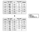
- FIG. 4 is a diagram for explaining a flow in which the battery control device 100 increases the charging current rate.
- the required time of the secondary battery 210b is “0.2h”, and the secondary battery 210b reaches the constant battery capacity earliest. Only the secondary battery 210c is charged within 0.2h. That is, there are only two secondary batteries, the secondary battery 210c and the secondary battery 210f, that have been fully charged after 0.2 hours have passed. Charging needs to be completed. Therefore, the battery control device 100 increases the charging current rate of one of the secondary batteries 210d and 210e that are being charged that does not become fully charged within the required time, and performs control so that the charging is completed within the required time.
- the battery control apparatus 100 selects the secondary battery 210d that is closest to the fully charged state as a target for increasing the charging current rate.
- This is the amount of charging current at which the charging current rate is “1C” in the secondary battery 210d.
- the battery control device 100 charges the secondary battery 210d with a charging current amount that is twice the original charging current rate (0.5C) and a charging current rate (1.0C).
- a predetermined number of fully charged secondary batteries can be prepared.
- the discharge current rate is calculated for each secondary battery 210 that is being discharged based on the amount of discharge current measured by the measurement unit 110. Then, based on the calculated discharge current rate of the secondary battery 210 being discharged and the SOC of the secondary battery 210, the time required to reach a predetermined battery capacity for each secondary battery 210 being discharged Is calculated. Further, a charging current rate is calculated for each secondary battery 210 being charged based on the amount of charging current of the secondary battery 210 being charged. Then, based on the calculated charging current rate of the secondary battery 210 being charged, the SOC of the secondary battery 210, and the required time, the expected number of secondary batteries 210 that are fully charged within the required time. Is calculated.
- a predetermined number of 2 that can secure a desired amount of power. It is determined whether or not the secondary battery 210 can be prepared within the required time. Based on the result of the determination, whether or not to increase the charging current rate of the secondary battery 210 being charged is controlled.
- the required number of fully charged secondary batteries can be secured, so that the amount of power desired by the user can be stabilized. Can be secured.
- the battery control device 100 may increase the charging current rate in order from the secondary batteries 210 belonging to the preset specific group.
- the specific group indicates a group to which the secondary battery 210 that is preferentially selected as a target for changing the charging current rate by the control unit 140 belongs.
- step S128 battery control device 100 selects a target whose charge current rate is to be increased from secondary batteries 210 that do not become fully charged within the required time and belong to a specific group.
- SOH State Of Health
- the range of SOH determined as a specific group is arbitrarily set by the user.
- the battery control apparatus 100 determines the secondary batteries 210 that have SOH in the range of 70% to less than 90% as the specific group described above.
- the battery control device 100 always uses the secondary battery 210 as a product. You may determine that it belongs to the normal charge group which charges with the charge current rate according to the specification.
- the battery control device 100 when the SOH of a certain secondary battery 210 is less than the lower limit value (70% in the above range) of a range determined as a specific group, the battery control device 100 always charges the secondary battery 210 with a charging current. You may judge that it belongs to the quick charge group which charges in the state which raised the rate. By doing in this way, the electrical storage apparatus 10 can be tuned according to a use, and the convenience improves.
- the second embodiment is the same as the first embodiment except for the following points.
- the number calculation unit 130 determines whether there is a secondary battery 210 that is fully charged before the required time elapses. Specifically, the number calculation unit 130 calculates the time until charging is completed (charging completion time) for each secondary battery 210 based on the charging current rate and SOC of each secondary battery 210 being charged. . Then, the number calculation unit 130 compares each calculated charging completion time with the required time, and determines whether there is a secondary battery 210 that is fully charged before the required time elapses. Then, the number calculation unit 130 transmits the result to the control unit 140.
- control unit 140 determines whether or not to decrease the charging current amount of the secondary battery 210 that is fully charged before the required time elapses.
- FIG. 5 is a flowchart showing a process flow of the battery control apparatus 100 according to the second embodiment.
- the battery control device 100 determines whether there is a secondary battery 210 that is fully charged before the required time elapses among the secondary batteries 210 being charged (S202). Specifically, the battery control device 100 determines the charging completion time of the secondary battery 210 based on the charging current rate calculated in S118 and the SOC of each secondary battery 210 being charged calculated in S120. Is calculated. Then, the battery control device 100 can determine whether or not the charging of the secondary battery 210 is completed before the required time elapses by comparing the calculated charging completion time and the required time. If there is a secondary battery 210 that is fully charged before the required time elapses (S202: YES), the battery control device 100 decreases the charging current rate of the secondary battery 210 (S204).
- the battery control device 100 may reduce the charging current rates of all the secondary batteries 210 among the secondary batteries 210 that are completely charged before the required time elapses. In order to secure electric power with a margin, only a part of the secondary batteries 210 may reduce the charging current rate.
- the battery control apparatus 100 can calculate a new charging current rate using Expression 4 as in the first embodiment.
- FIG. 6 is a diagram for explaining a flow in which the battery control device 100 decreases the charging current rate.
- the required time of the secondary battery 210b is “0.2h”, and the secondary battery 210b reaches the constant battery capacity earliest. And it is the secondary battery 210c that completes charging before 0.2h elapses.
- the battery capacity at the time of full charge of the secondary battery 210c is assumed to be 5 [Ah]
- the battery control device 100 charges the secondary battery 210c with a charging current amount that becomes a charging current rate (0.25C) that is 1 ⁇ 2 times the original charging current rate (0.5C). Thereby, even when the charging current rate is lowered, a predetermined number of fully charged secondary batteries 210 can be prepared within a required time.
- the charging completion time is calculated for each secondary battery 210 based on the charging current rate and SOC of each secondary battery 210 being charged. Then, based on each calculated charging completion time and the required time, it is determined whether or not there is a secondary battery 210 that is fully charged before the required time elapses. Then, based on the result, it is controlled whether or not to reduce the amount of charging current of the secondary battery 210 that is completely charged before the required time elapses.
- the third embodiment is the same as the first embodiment or the second embodiment except for the following points. Below, it demonstrates based on 1st Embodiment.
- the battery control device 100 weights the number of fully charged secondary batteries 210 in accordance with deterioration that occurs due to charge / discharge or the like.
- FIG. 7 is a diagram illustrating a configuration example of the battery control device 100 according to the third embodiment.
- the number calculation unit 130 includes an SOH storage unit 132 and a weighting unit 134.
- the SOH storage unit 132 stores a deterioration state (SOH) for each secondary battery 210.
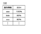
- FIG. 8 is a diagram illustrating an example of information stored in the SOH storage unit 132.
- information for individually identifying each secondary battery 210 included in the battery unit 200 is stored in the identification information column.
- This identification information is, for example, the serial number of each secondary battery 210 or the like.
- the SOH column the SOH of each secondary battery 210 is stored.
- This SOH is calculated using, for example, the above equation 6 when the charging of each secondary battery 210 is completed, and stored in the SOH storage unit 132.
- the SOH storage unit 132 may be included in another processing unit other than the number calculation unit 130 or another device located outside the battery control device 100.
- the weighting unit 134 reads the SOH from the SOH storage unit 132 based on the identification information for each secondary battery 210, and weights the planned number and the existing number based on the SOH.
- FIG. 9 is a flowchart illustrating a process flow of the battery control device 100 according to the third embodiment.
- the battery control apparatus 100 adds the number of fully charged secondary batteries weighted based on SOH to the existing number (S302). Specifically, the battery control device 100 reads the SOH of the corresponding secondary battery 210 from the SOH storage unit 132 based on the identification information of the secondary battery 210 that has already been charged. Then, the battery control apparatus 100 adds the number weighted based on the read SOH to the existing number stored in the existing number storage unit 150. For example, when information as shown in FIG.
- the battery control device 100 calculates the planned number of secondary batteries that are fully charged within the required time weighted based on the SOH (S304). Specifically, the battery control device 100 reads the SOH of the corresponding secondary battery 210 from the SOH storage unit 132 based on the identification information for each secondary battery 210 that is fully charged within the required time. Then, the battery control device 100 adds the weighted numbers based on the read SOH, and calculates the planned number. For example, when the information as shown in FIG.
- the planned number and the existing number are weighted according to the deterioration state of each secondary battery 210. Then, it is determined whether or not a predetermined number of secondary batteries 210 capable of securing a desired amount of power are secured based on the summed value of the weighted scheduled number and the existing number. Thereby, the electric energy which a user desires can be ensured more stably.
- the battery control device 100 stores a plurality of charging current rates divided in stages, and when changing the charging current rate, the charging current that can be charged within the required time. A rate may be selected.
- measuring means for individually measuring a discharge current amount of the secondary battery being discharged; Based on the discharge current rate for each secondary battery calculated based on the discharge current amount and the SOC (State Of Charge) of the secondary battery, for each secondary battery being discharged, the secondary battery Time calculating means for calculating the time required until the battery reaches a certain battery capacity, Fully charged within the required time based on the charging current rate for each secondary battery calculated based on the charging current amount of the secondary battery being charged, the SOC of the secondary battery, and the required time
- a number calculating means for calculating a planned number of the secondary batteries to be in a state and calculating a sum of the planned number and the existing number of secondary batteries that are already fully charged; Control means for determining whether to increase the charging current rate based on the total value; A battery control device.
- the control means increases the charging current rate in order from the secondary battery closest to full charge among the secondary batteries being charged that do not become fully charged within the required time.
- the battery control device according to appendix 1. (Appendix 3) The control means increases the charging current rate by an increase of 2 times or more, The battery control device according to appendix 1 or 2. (Appendix 4) The control means lowers the charging current rate based on a charging completion time for each secondary battery being charged and the required time.
- the battery control device according to any one of appendices 1 to 3. (Appendix 5)
- the control means increases the charging current rate in order from the secondary battery belonging to a specific group to be targeted for increasing the charging current rate.
- the specific group is classified based on SOH (State Of Health) for each of the plurality of secondary batteries.
- the battery control device according to appendix 5.
- the number calculating means weights the planned number and the existing number based on SOH for each of the plurality of secondary batteries.
- the battery control device according to any one of appendices 1 to 6.
- a number calculating means for calculating a planned number of the secondary batteries to be in a state and calculating a sum of the planned number and the existing number of secondary batteries that are already fully charged; Control means for determining whether to increase the charging current rate based on the total value; A power storage device.
- Computer Measuring means for individually measuring a discharge current amount of the secondary battery being discharged among a plurality of secondary batteries that are charged and discharged independently; Based on the discharge current rate for each secondary battery calculated based on the discharge current amount and the SOC (State Of Charge) of the secondary battery, for each secondary battery being discharged, the secondary battery Time calculation means for calculating the time required until the battery reaches a certain battery capacity, Fully charged within the required time based on the charging current rate for each secondary battery calculated based on the charging current amount of the secondary battery being charged, the SOC of the secondary battery, and the required time
- a number calculating means for calculating a planned number of the secondary batteries that are in a state and calculating a sum of the planned number and the existing number of secondary batteries that are already fully charged; Control means for determining whether to increase the charging current rate based on the total value; Program to function as.
- the control means increases the charging current rate in order from the secondary battery closest to full charge among the secondary batteries being charged that do not become fully charged within the required time.
- the power storage device according to appendix 8. The control means increases the charging current rate by an increase of 2 times or more, The power storage device according to appendix 8 or 11.
- the control means lowers the charging current rate based on a charging completion time for each secondary battery being charged and the required time.
- the control means increases the charging current rate in order from the secondary battery belonging to a specific group to be targeted for increasing the charging current rate.
- (Appendix 15) The specific group is classified based on SOH (State Of Health) for each of the plurality of secondary batteries.
- the number calculating means weights the planned number and the existing number based on SOH for each of the plurality of secondary batteries.
- (Appendix 17) The computer increases the charging current rate in order from the secondary battery that is closest to full charge among the secondary batteries that are not fully charged within the required time.
- (Appendix 18) The computer increases the charging current rate by more than twice as much; The electricity storage method according to appendix 9 or 17, including the above.
- the computer reduces the charging current rate based on a charging completion time for each of the secondary batteries being charged and the required time;
- the computer increases the charging current rate in order from the secondary battery belonging to a specific group targeted for increasing the charging current rate.
- the specific group is classified based on SOH (State Of Health) for each of the plurality of secondary batteries.
- the computer weights the planned number and the existing number based on SOH for each of the plurality of secondary batteries.
- the electricity storage method according to any one of Supplementary Note 9 and 17 to 21.
- (Appendix 23) Means for increasing the charging current rate in order from the secondary battery closest to full charge among the secondary batteries being charged that do not become fully charged within the required time in the computer;
- the program according to appendix 10 for functioning as: (Appendix 24) Means for increasing the charging current rate at a rate of increase of 2 or more times for the computer;
- the program according to any one of supplementary notes 10 and 23 to 25 for causing the program to function as a program.
- (Appendix 27) Means for classifying the plurality of secondary batteries into a specific group based on SOH (State Of Health) for each of the plurality of secondary batteries;
- (Appendix 28) Means for weighting the planned number and the existing number based on SOH for each of the plurality of secondary batteries;
Landscapes
- Engineering & Computer Science (AREA)
- Power Engineering (AREA)
- Manufacturing & Machinery (AREA)
- Chemical & Material Sciences (AREA)
- Chemical Kinetics & Catalysis (AREA)
- Electrochemistry (AREA)
- General Chemical & Material Sciences (AREA)
- Charge And Discharge Circuits For Batteries Or The Like (AREA)
- Secondary Cells (AREA)
Abstract
Priority Applications (3)
| Application Number | Priority Date | Filing Date | Title |
|---|---|---|---|
| RU2015121969/07A RU2600313C1 (ru) | 2012-11-09 | 2013-11-01 | Устройство управления батареей, устройство накопления энергии, способ накопления энергии и программа |
| US14/440,526 US9735596B2 (en) | 2012-11-09 | 2013-11-01 | Battery control device, power storage device, power storage method, and program |
| EP13852443.4A EP2919361A4 (fr) | 2012-11-09 | 2013-11-01 | Contrôleur de batterie, dispositif de stockage d'énergie, procédé de stockage d'énergie et programme |
Applications Claiming Priority (2)
| Application Number | Priority Date | Filing Date | Title |
|---|---|---|---|
| JP2012-247572 | 2012-11-09 | ||
| JP2012247572A JP6068100B2 (ja) | 2012-11-09 | 2012-11-09 | 電池制御装置、蓄電装置、蓄電方法、及びプログラム |
Publications (1)
| Publication Number | Publication Date |
|---|---|
| WO2014073475A1 true WO2014073475A1 (fr) | 2014-05-15 |
Family
ID=50684581
Family Applications (1)
| Application Number | Title | Priority Date | Filing Date |
|---|---|---|---|
| PCT/JP2013/079689 Ceased WO2014073475A1 (fr) | 2012-11-09 | 2013-11-01 | Contrôleur de batterie, dispositif de stockage d'énergie, procédé de stockage d'énergie et programme |
Country Status (5)
| Country | Link |
|---|---|
| US (1) | US9735596B2 (fr) |
| EP (1) | EP2919361A4 (fr) |
| JP (1) | JP6068100B2 (fr) |
| RU (1) | RU2600313C1 (fr) |
| WO (1) | WO2014073475A1 (fr) |
Cited By (1)
| Publication number | Priority date | Publication date | Assignee | Title |
|---|---|---|---|---|
| US9883787B2 (en) | 2014-06-19 | 2018-02-06 | Olympus Corporation | Medical apparatus system |
Families Citing this family (10)
| Publication number | Priority date | Publication date | Assignee | Title |
|---|---|---|---|---|
| US10128656B2 (en) | 2014-06-17 | 2018-11-13 | Samsung Sdi Co., Ltd. | Power assist unit and power assist system |
| US9812901B2 (en) * | 2014-11-19 | 2017-11-07 | Thomas & Betts International Llc | Emergency lighting battery charger |
| WO2017094311A1 (fr) * | 2015-12-01 | 2017-06-08 | ソニー株式会社 | Circuit intégré de gestion de puissance, dispositif électronique et procédé de commande de circuit intégré de gestion de puissance |
| US10416753B1 (en) * | 2015-12-10 | 2019-09-17 | Amazon Technologies, Inc. | Date-based computing device charge management |
| JP2021083133A (ja) | 2018-03-12 | 2021-05-27 | 嵩 亀澤 | 定電圧直流供給装置 |
| KR102743393B1 (ko) | 2019-09-06 | 2024-12-16 | 주식회사 엘지에너지솔루션 | 배터리 관리 장치, 배터리 관리 방법, 배터리 팩 및 전기 차량 |
| JP7191873B2 (ja) * | 2020-01-17 | 2022-12-19 | 株式会社東芝 | 充放電制御装置、充放電システム、充放電制御方法及び充放電制御プログラム |
| JP7436317B2 (ja) * | 2020-07-29 | 2024-02-21 | 日立建機株式会社 | 電動作業機械 |
| KR102888316B1 (ko) | 2021-01-08 | 2025-11-18 | 주식회사 엘지에너지솔루션 | 최대 방전 전류 예측 방법 및 이를 이용한 배터리 시스템 |
| KR20240024696A (ko) * | 2022-08-17 | 2024-02-26 | 주식회사 엘지에너지솔루션 | 충전 시간 예측 장치 및 그의 동작 방법 |
Citations (6)
| Publication number | Priority date | Publication date | Assignee | Title |
|---|---|---|---|---|
| JPS59206680A (ja) | 1983-05-10 | 1984-11-22 | Nippon Zosen Shinko Zaidan | 浮体による波エネルギ−発電装置 |
| JPH02270270A (ja) | 1989-04-11 | 1990-11-05 | Meidensha Corp | 亜鉛―臭素電池の運転方法 |
| JP2001045677A (ja) * | 1999-07-29 | 2001-02-16 | Sekisui Chem Co Ltd | 太陽電池利用電力供給装置 |
| JP2007508795A (ja) * | 2003-10-08 | 2007-04-05 | エナージイ アンド エンジン テクノロジイ コーポレーション | バッテリ電力を管理するための方法およびシステム |
| JP2009247108A (ja) * | 2008-03-31 | 2009-10-22 | Furukawa Battery Co Ltd:The | 蓄電装置及びその充放電制御方法 |
| JP2012525117A (ja) * | 2010-06-16 | 2012-10-18 | ジングァン チュ | 電源供給装置 |
Family Cites Families (5)
| Publication number | Priority date | Publication date | Assignee | Title |
|---|---|---|---|---|
| US5422560A (en) * | 1991-09-30 | 1995-06-06 | Telcom Semiconductor, Inc. | Battery charger with battery detection circuit |
| RU2329582C2 (ru) | 2006-07-11 | 2008-07-20 | ФГУП "Северное проектно-конструкторское бюро" | Способ зарядки аккумуляторов с компоновкой их в систему по принципу разделения емкостей |
| US7671559B2 (en) | 2007-07-31 | 2010-03-02 | Apple Inc. | Battery charging system and mobile and accessory devices |
| US20090243549A1 (en) * | 2008-03-31 | 2009-10-01 | Naoki Matsumura | Intelligent battery charging rate management |
| RU91482U1 (ru) | 2009-09-11 | 2010-02-10 | Некоммерческое партнерство "Инновации в электроэнергетике" (НП "ИНВЭЛ") | Устройство для многопостовой зарядки аккумуляторов |
-
2012
- 2012-11-09 JP JP2012247572A patent/JP6068100B2/ja not_active Expired - Fee Related
-
2013
- 2013-11-01 US US14/440,526 patent/US9735596B2/en not_active Expired - Fee Related
- 2013-11-01 WO PCT/JP2013/079689 patent/WO2014073475A1/fr not_active Ceased
- 2013-11-01 EP EP13852443.4A patent/EP2919361A4/fr not_active Withdrawn
- 2013-11-01 RU RU2015121969/07A patent/RU2600313C1/ru not_active IP Right Cessation
Patent Citations (6)
| Publication number | Priority date | Publication date | Assignee | Title |
|---|---|---|---|---|
| JPS59206680A (ja) | 1983-05-10 | 1984-11-22 | Nippon Zosen Shinko Zaidan | 浮体による波エネルギ−発電装置 |
| JPH02270270A (ja) | 1989-04-11 | 1990-11-05 | Meidensha Corp | 亜鉛―臭素電池の運転方法 |
| JP2001045677A (ja) * | 1999-07-29 | 2001-02-16 | Sekisui Chem Co Ltd | 太陽電池利用電力供給装置 |
| JP2007508795A (ja) * | 2003-10-08 | 2007-04-05 | エナージイ アンド エンジン テクノロジイ コーポレーション | バッテリ電力を管理するための方法およびシステム |
| JP2009247108A (ja) * | 2008-03-31 | 2009-10-22 | Furukawa Battery Co Ltd:The | 蓄電装置及びその充放電制御方法 |
| JP2012525117A (ja) * | 2010-06-16 | 2012-10-18 | ジングァン チュ | 電源供給装置 |
Non-Patent Citations (1)
| Title |
|---|
| See also references of EP2919361A4 |
Cited By (1)
| Publication number | Priority date | Publication date | Assignee | Title |
|---|---|---|---|---|
| US9883787B2 (en) | 2014-06-19 | 2018-02-06 | Olympus Corporation | Medical apparatus system |
Also Published As
| Publication number | Publication date |
|---|---|
| US9735596B2 (en) | 2017-08-15 |
| RU2600313C1 (ru) | 2016-10-20 |
| EP2919361A1 (fr) | 2015-09-16 |
| JP6068100B2 (ja) | 2017-01-25 |
| JP2014096940A (ja) | 2014-05-22 |
| US20150318726A1 (en) | 2015-11-05 |
| EP2919361A4 (fr) | 2016-08-10 |
Similar Documents
| Publication | Publication Date | Title |
|---|---|---|
| JP6068100B2 (ja) | 電池制御装置、蓄電装置、蓄電方法、及びプログラム | |
| KR101725701B1 (ko) | 복수 전지를 갖는 이차 전지 시스템 및 충방전 전력 또는 전류의 배분 방법 | |
| JP4405558B2 (ja) | 充電状態を用いた電池平滑化システム及び方法 | |
| JP5975169B2 (ja) | 充放電装置、充放電制御方法、及びプログラム | |
| CN110870130B (zh) | 蓄电池系统充电控制装置、蓄电池系统以及蓄电池充电控制方法 | |
| CN105993094B (zh) | 用于控制电池组的多个电池的设备和方法 | |
| US9257863B2 (en) | Charge and discharge control device and charge and discharge control method | |
| EP2824789B1 (fr) | Procédé de commande de fréquence | |
| CN103311958B (zh) | 电力供需控制装置 | |
| US20150008884A1 (en) | Storage battery control apparatus, storage battery control method, and storage battery system | |
| WO2019239640A1 (fr) | Dispositif et procédé de commande d'un système d'accumulateurs | |
| EP3273524A1 (fr) | Dispositif, procédé et programme de gestion de batterie rechargeable | |
| JP2023112691A (ja) | 電源システム、電源システムの制御方法、およびプログラム | |
| TWI646750B (zh) | 儲能系統及其充放電方法 | |
| JP2013183509A (ja) | 充放電量予測システム及び充放電量予測方法 | |
| KR101621123B1 (ko) | 배터리 관리 시스템 | |
| JP6587466B2 (ja) | バッテリの試験装置 | |
| JP2020188669A (ja) | 車両充電システム | |
| EP4510421A1 (fr) | Dispositif de commande de charge/décharge, procédé de commande de charge/décharge, et programme | |
| JP2017225212A (ja) | 充放電制御装置 | |
| EP3116081A1 (fr) | Procédé de commande de l'énergie électrique reçue, dispositif de commande de l'énergie électrique reçue et appareil électrique | |
| KR101491460B1 (ko) | 배터리의 액티브 셀 밸런싱 방법 및 이를 이용한 시스템 | |
| JP2018169238A (ja) | 蓄電制御装置、蓄電制御システム、サーバ、蓄電制御方法及びプログラム | |
| JP6447093B2 (ja) | 電力管理システム | |
| JP2018045844A (ja) | 蓄電装置診断システムおよび蓄電装置診断方法 |
Legal Events
| Date | Code | Title | Description |
|---|---|---|---|
| 121 | Ep: the epo has been informed by wipo that ep was designated in this application |
Ref document number: 13852443 Country of ref document: EP Kind code of ref document: A1 |
|
| REEP | Request for entry into the european phase |
Ref document number: 2013852443 Country of ref document: EP |
|
| WWE | Wipo information: entry into national phase |
Ref document number: 2013852443 Country of ref document: EP |
|
| WWE | Wipo information: entry into national phase |
Ref document number: 14440526 Country of ref document: US |
|
| NENP | Non-entry into the national phase |
Ref country code: DE |
|
| ENP | Entry into the national phase |
Ref document number: 2015121969 Country of ref document: RU Kind code of ref document: A |