WO2014077400A1 - 直動型反応処理装置およびその方法 - Google Patents
直動型反応処理装置およびその方法 Download PDFInfo
- Publication number
- WO2014077400A1 WO2014077400A1 PCT/JP2013/081082 JP2013081082W WO2014077400A1 WO 2014077400 A1 WO2014077400 A1 WO 2014077400A1 JP 2013081082 W JP2013081082 W JP 2013081082W WO 2014077400 A1 WO2014077400 A1 WO 2014077400A1
- Authority
- WO
- WIPO (PCT)
- Prior art keywords
- reaction
- container
- dispensing
- sample
- liquid
- Prior art date
- Legal status (The legal status is an assumption and is not a legal conclusion. Google has not performed a legal analysis and makes no representation as to the accuracy of the status listed.)
- Ceased
Links
Images








Classifications
-
- G—PHYSICS
- G01—MEASURING; TESTING
- G01N—INVESTIGATING OR ANALYSING MATERIALS BY DETERMINING THEIR CHEMICAL OR PHYSICAL PROPERTIES
- G01N35/00—Automatic analysis not limited to methods or materials provided for in any single one of groups G01N1/00 - G01N33/00; Handling materials therefor
- G01N35/0098—Automatic analysis not limited to methods or materials provided for in any single one of groups G01N1/00 - G01N33/00; Handling materials therefor involving analyte bound to insoluble magnetic carrier, e.g. using magnetic separation
-
- B—PERFORMING OPERATIONS; TRANSPORTING
- B01—PHYSICAL OR CHEMICAL PROCESSES OR APPARATUS IN GENERAL
- B01L—CHEMICAL OR PHYSICAL LABORATORY APPARATUS FOR GENERAL USE
- B01L7/00—Heating or cooling apparatus; Heat insulating devices
- B01L7/52—Heating or cooling apparatus; Heat insulating devices with provision for submitting samples to a predetermined sequence of different temperatures, e.g. for treating nucleic acid samples
-
- C—CHEMISTRY; METALLURGY
- C12—BIOCHEMISTRY; BEER; SPIRITS; WINE; VINEGAR; MICROBIOLOGY; ENZYMOLOGY; MUTATION OR GENETIC ENGINEERING
- C12N—MICROORGANISMS OR ENZYMES; COMPOSITIONS THEREOF; PROPAGATING, PRESERVING, OR MAINTAINING MICROORGANISMS; MUTATION OR GENETIC ENGINEERING; CULTURE MEDIA
- C12N15/00—Mutation or genetic engineering; DNA or RNA concerning genetic engineering, vectors, e.g. plasmids, or their isolation, preparation or purification; Use of hosts therefor
- C12N15/09—Recombinant DNA-technology
- C12N15/10—Processes for the isolation, preparation or purification of DNA or RNA
- C12N15/1003—Extracting or separating nucleic acids from biological samples, e.g. pure separation or isolation methods; Conditions, buffers or apparatuses therefor
- C12N15/1006—Extracting or separating nucleic acids from biological samples, e.g. pure separation or isolation methods; Conditions, buffers or apparatuses therefor by means of a solid support carrier, e.g. particles, polymers
- C12N15/1013—Extracting or separating nucleic acids from biological samples, e.g. pure separation or isolation methods; Conditions, buffers or apparatuses therefor by means of a solid support carrier, e.g. particles, polymers by using magnetic beads
-
- G—PHYSICS
- G01—MEASURING; TESTING
- G01N—INVESTIGATING OR ANALYSING MATERIALS BY DETERMINING THEIR CHEMICAL OR PHYSICAL PROPERTIES
- G01N21/00—Investigating or analysing materials by the use of optical means, i.e. using sub-millimetre waves, infrared, visible or ultraviolet light
- G01N21/62—Systems in which the material investigated is excited whereby it emits light or causes a change in wavelength of the incident light
- G01N21/63—Systems in which the material investigated is excited whereby it emits light or causes a change in wavelength of the incident light optically excited
- G01N21/64—Fluorescence; Phosphorescence
- G01N21/6428—Measuring fluorescence of fluorescent products of reactions or of fluorochrome labelled reactive substances, e.g. measuring quenching effects, using measuring "optrodes"
-
- G—PHYSICS
- G01—MEASURING; TESTING
- G01N—INVESTIGATING OR ANALYSING MATERIALS BY DETERMINING THEIR CHEMICAL OR PHYSICAL PROPERTIES
- G01N21/00—Investigating or analysing materials by the use of optical means, i.e. using sub-millimetre waves, infrared, visible or ultraviolet light
- G01N21/62—Systems in which the material investigated is excited whereby it emits light or causes a change in wavelength of the incident light
- G01N21/63—Systems in which the material investigated is excited whereby it emits light or causes a change in wavelength of the incident light optically excited
- G01N21/64—Fluorescence; Phosphorescence
- G01N21/645—Specially adapted constructive features of fluorimeters
- G01N21/6452—Individual samples arranged in a regular 2D-array, e.g. multiwell plates
-
- G—PHYSICS
- G01—MEASURING; TESTING
- G01N—INVESTIGATING OR ANALYSING MATERIALS BY DETERMINING THEIR CHEMICAL OR PHYSICAL PROPERTIES
- G01N35/00—Automatic analysis not limited to methods or materials provided for in any single one of groups G01N1/00 - G01N33/00; Handling materials therefor
- G01N35/00584—Control arrangements for automatic analysers
- G01N35/00722—Communications; Identification
- G01N35/00732—Identification of carriers, materials or components in automatic analysers
-
- G—PHYSICS
- G01—MEASURING; TESTING
- G01N—INVESTIGATING OR ANALYSING MATERIALS BY DETERMINING THEIR CHEMICAL OR PHYSICAL PROPERTIES
- G01N35/00—Automatic analysis not limited to methods or materials provided for in any single one of groups G01N1/00 - G01N33/00; Handling materials therefor
- G01N35/10—Devices for transferring samples or any liquids to, in, or from, the analysis apparatus, e.g. suction devices, injection devices
-
- B—PERFORMING OPERATIONS; TRANSPORTING
- B01—PHYSICAL OR CHEMICAL PROCESSES OR APPARATUS IN GENERAL
- B01L—CHEMICAL OR PHYSICAL LABORATORY APPARATUS FOR GENERAL USE
- B01L2200/00—Solutions for specific problems relating to chemical or physical laboratory apparatus
- B01L2200/06—Fluid handling related problems
- B01L2200/0647—Handling flowable solids, e.g. microscopic beads, cells, particles
-
- B—PERFORMING OPERATIONS; TRANSPORTING
- B01—PHYSICAL OR CHEMICAL PROCESSES OR APPARATUS IN GENERAL
- B01L—CHEMICAL OR PHYSICAL LABORATORY APPARATUS FOR GENERAL USE
- B01L2300/00—Additional constructional details
- B01L2300/04—Closures and closing means
- B01L2300/041—Connecting closures to device or container
- B01L2300/044—Connecting closures to device or container pierceable, e.g. films, membranes
-
- B—PERFORMING OPERATIONS; TRANSPORTING
- B01—PHYSICAL OR CHEMICAL PROCESSES OR APPARATUS IN GENERAL
- B01L—CHEMICAL OR PHYSICAL LABORATORY APPARATUS FOR GENERAL USE
- B01L2300/00—Additional constructional details
- B01L2300/08—Geometry, shape and general structure
- B01L2300/0861—Configuration of multiple channels and/or chambers in a single devices
-
- B—PERFORMING OPERATIONS; TRANSPORTING
- B01—PHYSICAL OR CHEMICAL PROCESSES OR APPARATUS IN GENERAL
- B01L—CHEMICAL OR PHYSICAL LABORATORY APPARATUS FOR GENERAL USE
- B01L2300/00—Additional constructional details
- B01L2300/18—Means for temperature control
- B01L2300/1805—Conductive heating, heat from thermostatted solids is conducted to receptacles, e.g. heating plates, blocks
- B01L2300/1822—Conductive heating, heat from thermostatted solids is conducted to receptacles, e.g. heating plates, blocks using Peltier elements
-
- B—PERFORMING OPERATIONS; TRANSPORTING
- B01—PHYSICAL OR CHEMICAL PROCESSES OR APPARATUS IN GENERAL
- B01L—CHEMICAL OR PHYSICAL LABORATORY APPARATUS FOR GENERAL USE
- B01L2400/00—Moving or stopping fluids
- B01L2400/04—Moving fluids with specific forces or mechanical means
- B01L2400/0403—Moving fluids with specific forces or mechanical means specific forces
- B01L2400/0433—Moving fluids with specific forces or mechanical means specific forces vibrational forces
- B01L2400/0439—Moving fluids with specific forces or mechanical means specific forces vibrational forces ultrasonic vibrations, vibrating piezo elements
-
- B—PERFORMING OPERATIONS; TRANSPORTING
- B01—PHYSICAL OR CHEMICAL PROCESSES OR APPARATUS IN GENERAL
- B01L—CHEMICAL OR PHYSICAL LABORATORY APPARATUS FOR GENERAL USE
- B01L3/00—Containers or dishes for laboratory use, e.g. laboratory glassware; Droppers
- B01L3/50—Containers for the purpose of retaining a material to be analysed, e.g. test tubes
- B01L3/508—Rigid containers without fluid transport within
- B01L3/5082—Test tubes per se
-
- G—PHYSICS
- G01—MEASURING; TESTING
- G01N—INVESTIGATING OR ANALYSING MATERIALS BY DETERMINING THEIR CHEMICAL OR PHYSICAL PROPERTIES
- G01N21/00—Investigating or analysing materials by the use of optical means, i.e. using sub-millimetre waves, infrared, visible or ultraviolet light
- G01N21/62—Systems in which the material investigated is excited whereby it emits light or causes a change in wavelength of the incident light
- G01N21/63—Systems in which the material investigated is excited whereby it emits light or causes a change in wavelength of the incident light optically excited
- G01N21/64—Fluorescence; Phosphorescence
- G01N21/6428—Measuring fluorescence of fluorescent products of reactions or of fluorochrome labelled reactive substances, e.g. measuring quenching effects, using measuring "optrodes"
- G01N2021/6439—Measuring fluorescence of fluorescent products of reactions or of fluorochrome labelled reactive substances, e.g. measuring quenching effects, using measuring "optrodes" with indicators, stains, dyes, tags, labels, marks
-
- G—PHYSICS
- G01—MEASURING; TESTING
- G01N—INVESTIGATING OR ANALYSING MATERIALS BY DETERMINING THEIR CHEMICAL OR PHYSICAL PROPERTIES
- G01N35/00—Automatic analysis not limited to methods or materials provided for in any single one of groups G01N1/00 - G01N33/00; Handling materials therefor
- G01N2035/00346—Heating or cooling arrangements
- G01N2035/00356—Holding samples at elevated temperature (incubation)
- G01N2035/00376—Conductive heating, e.g. heated plates
-
- G—PHYSICS
- G01—MEASURING; TESTING
- G01N—INVESTIGATING OR ANALYSING MATERIALS BY DETERMINING THEIR CHEMICAL OR PHYSICAL PROPERTIES
- G01N35/00—Automatic analysis not limited to methods or materials provided for in any single one of groups G01N1/00 - G01N33/00; Handling materials therefor
- G01N35/02—Automatic analysis not limited to methods or materials provided for in any single one of groups G01N1/00 - G01N33/00; Handling materials therefor using a plurality of sample containers moved by a conveyor system past one or more treatment or analysis stations
- G01N35/04—Details of the conveyor system
- G01N2035/0401—Sample carriers, cuvettes or reaction vessels
- G01N2035/0412—Block or rack elements with a single row of samples
-
- G—PHYSICS
- G01—MEASURING; TESTING
- G01N—INVESTIGATING OR ANALYSING MATERIALS BY DETERMINING THEIR CHEMICAL OR PHYSICAL PROPERTIES
- G01N35/00—Automatic analysis not limited to methods or materials provided for in any single one of groups G01N1/00 - G01N33/00; Handling materials therefor
- G01N35/10—Devices for transferring samples or any liquids to, in, or from, the analysis apparatus, e.g. suction devices, injection devices
- G01N2035/1027—General features of the devices
- G01N2035/1048—General features of the devices using the transfer device for another function
- G01N2035/1053—General features of the devices using the transfer device for another function for separating part of the liquid, e.g. filters, extraction phase
-
- G—PHYSICS
- G01—MEASURING; TESTING
- G01N—INVESTIGATING OR ANALYSING MATERIALS BY DETERMINING THEIR CHEMICAL OR PHYSICAL PROPERTIES
- G01N35/00—Automatic analysis not limited to methods or materials provided for in any single one of groups G01N1/00 - G01N33/00; Handling materials therefor
- G01N35/10—Devices for transferring samples or any liquids to, in, or from, the analysis apparatus, e.g. suction devices, injection devices
- G01N35/1002—Reagent dispensers
-
- G—PHYSICS
- G01—MEASURING; TESTING
- G01N—INVESTIGATING OR ANALYSING MATERIALS BY DETERMINING THEIR CHEMICAL OR PHYSICAL PROPERTIES
- G01N35/00—Automatic analysis not limited to methods or materials provided for in any single one of groups G01N1/00 - G01N33/00; Handling materials therefor
- G01N35/10—Devices for transferring samples or any liquids to, in, or from, the analysis apparatus, e.g. suction devices, injection devices
- G01N35/1065—Multiple transfer devices
Definitions
- the present invention relates to a direct acting reaction processing apparatus and method.
- a liquid container equal to the number of treatment steps is prepared, and a liquid such as a necessary reagent solution for treatment is used as a reagent. Dispense and arrange from the container for each process. After the arrangement is completed, using the dispensing device, the liquid contained in each liquid container is sucked or sucked after repeated suction and discharge, and the magnetic particles are applied to the dispensing tip by applying a magnetic field.
- Patent Documents 1 and 2 Adsorbing and separating on the inner wall, discharging the remaining liquid for each liquid container, moving the dispensing tip to the next liquid container with the magnetic particles adsorbed on the inner wall, and performing the same processing The number of processing steps is repeated (Patent Documents 1 and 2).
- the separated and extracted target substance is transferred and introduced into the reaction vessel together with the reaction solution by a method or the like, and the reaction is performed.
- the reaction was performed using a reaction temperature controller after the container was sealed by a method or the like, optical measurement was performed on the reaction container using an optical measuring device.
- each process when executed by a method, it imposes a heavy burden on the user, and each process is performed by a dispenser, a centrifuge, a magnetic device, a temperature controller, a reaction vessel sealing device, an optical device.
- a dispenser When the measurement apparatus is combined and executed, there is a possibility that the scale of the apparatus used increases and the work area increases.
- the work area In particular, in order to handle each nucleic acid extracted from a plurality of samples (analytes), it is necessary to amplify each nucleic acid, and therefore the labor is further increased, and the work area may be further increased.
- a first object of the present invention is to reliably prevent cross-contamination and to determine the number of containers or liquid storage units used for the reaction process. It is to provide a direct acting reaction processing apparatus and a method thereof with high spatial efficiency by reducing the working space.
- the second object is to reduce the pre-processing time and to increase the reactivity of the test object, thereby shortening the working time of the entire reaction process and improving the time efficiency of the direct acting reaction processing apparatus and method Is to provide.
- a third object is to provide a direct-acting reaction processing apparatus suitable for automation and a method thereof that can increase the reliability of the entire process by automating the pretreatment with high reliability.
- the fourth purpose is to simplify the structure of the optical system and perform measurement using a small number of measuring devices for a plurality of reaction vessels, thereby preventing an increase in the scale of the apparatus and a complicated structure of the apparatus. It is another object of the present invention to provide a direct-acting reaction processing apparatus and method that can be manufactured and used.
- the fifth object is to consistently automate optical measurements and the processes associated therewith for a plurality of reaction vessels in which reactions such as nucleic acid amplification are performed, so that the reaction from outside to the plurality of reaction vessels can be performed.
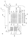
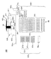
- one or two or more reaction containers, and a group of containers in which two or more liquid storage units are arranged in a series of at least one row, and the reaction container and the liquid storage unit can be inserted.
- One or more dispensing tips for sucking and discharging the liquid through the tip are detachably mounted, and move relatively in the series arrangement direction between the mounted dispensing tips and the container group.
- a possible dispensing head and a magnetic field which is provided in the dispensing head and exerts a magnetic field in each dispensing tip to adsorb and separate the magnetic particles contained in the liquid in each dispensing tip on its inner wall Removing the adsorbed magnetic particles and resuspending them in the liquid, and using at least one of the liquid storage parts as a sample storage part, applying ultrasonic vibration to the sample storage part
- a direct acting reaction processing apparatus having an ultrasonic vibrator It is.
- the “dispensing head” is provided with one or more nozzles for sucking and discharging gas, and the mounting opening provided on the upper side of the dispensing tip is a nozzle. It is used by being detachably mounted. Since it is “relative”, the dispensing head may move, the container group may move, and both may move.
- the linear reaction type processing apparatus is provided with a dispensing head moving mechanism or a container group moving mechanism as a “series moving mechanism” for moving the dispensing head relative to the container group at least in the series arrangement direction. Will be. However, the movement between the dispensing tip and the container group requires movement in the vertical direction in addition to movement in the series arrangement direction.
- the movement of the dispensing tips in the serial arrangement direction can use the dispensing head moving mechanism or the container group moving mechanism, but the vertical movement of the dispensing tips can be performed by the dispensing head moving mechanism or the container group.
- the movement mechanism is used and cases where a “vertical movement mechanism” of the dispensing tip is provided separately from the dispensing head movement mechanism or the container group movement mechanism.
- the dispensing head or container group only needs to move in the series arrangement direction. This load can be reduced, the life of the apparatus can be extended, and the apparatus structure can be simplified.
- reaction container is a container in which a reaction is performed
- liquid storage part is a container that can store a liquid.
- “(Each two or more objects are arranged in series)” means, for example, a function performing part of each arranged object (for example, if the object is a container or a container, the container or the container The function of the figure projected on the reference plane (usually a horizontal plane in the case of a container) on which the objects are arranged for the storage space or opening that engages with the nozzle or tip of the dispensing head This is a case where the positions (for example, geometric gravity center positions) of possible points (points where the tip of the dispensing tip can be inserted) are arranged so as to lie on a straight line drawn on the plane . The direction of the straight line is the “series arrangement direction”.
- the “container group” for example, a microplate in which wells as a plurality of various containing parts including a liquid containing part are arranged in a matrix or a row (row), or wells as a plurality of containing parts are arranged in a row.
- a cartridge-like container for example, a microplate in which wells as a plurality of various containing parts including a liquid containing part are arranged in a matrix or a row (row), or wells as a plurality of containing parts are arranged in a row.
- the volume of the “reaction vessel” is, for example, about 10 ⁇ l to 10 ml, and therefore the amount of liquid to be handled is smaller than this, from 1 ⁇ l to several thousand ⁇ l, and the capacity of the dispensing tip is , It is necessary to form it equal to or larger than the capacity of the reaction vessel, for example, about 10 ⁇ l to 10 ml.
- the reaction vessel is formed of, for example, an organic substance such as polypropylene, polyester, polyethylene, or acrylic, or an inorganic substance such as ceramic or metal.
- the temperature inside the reaction vessel can be controlled by a temperature controller.
- the “temperature controller” has a temperature source capable of raising or lowering the temperature in the reaction container containing the liquid to be temperature controlled based on an external signal or the like.
- the block-like member is provided with, for example, a Peltier element, a heater, a cooling device and the like.
- a thermal cycler using a Peltier element is preferable as the temperature controller. That is, the container group or stage is provided with a temperature control block whose temperature is raised or lowered by a Peltier element as a temperature source in contact with or close to a part (for example, the lower wall part) or the whole of the reaction container. It is preferable that the temperature is controlled by. It is also possible to perform isothermal amplification temperature control by the LAMP method.
- Temperature control means that a target liquid or container is maintained at one or two or more set predetermined temperatures for a set time in accordance with a set order. It is. The temperature controller is instructed by sending a corresponding signal based on a program.
- the “predetermined temperature” is a target temperature to be reached by an object such as a target liquid.
- a nucleic acid such as DNA contained in the liquid or an oligonucleotide that is a fragment of the nucleic acid is amplified by a PCR method.
- the predetermined temperature to be set is, for example, a temperature cycle performed by the PCR method, that is, each temperature necessary for DNA denaturation, annealing or hybridization, extension, about 94 ° C., 50 ° C. to 60 ° C. A temperature between 0 ° C and about 72 ° C.
- the temperature is set to a constant temperature, for example, 55 ° C.
- the predetermined temperature can be cooled by a temperature controller at a transition promoting temperature lower than these predetermined temperatures.
- a temperature controller at the time of transition from a predetermined temperature of low temperature to a predetermined temperature of high temperature, heating is performed at a temperature for promoting transition higher than these predetermined temperatures, thereby shortening the transition time and reducing one cycle time.
- transition-promoting temperature is the time required to maintain each temperature, and depends on the type of amplification method, the reagent and liquid amount used in the PCR method, the shape, material, size, thickness, etc.
- the total is, for example, several seconds to several tens of seconds
- the processing time of the entire PCR method is, for example, about several minutes to several tens of minutes.
- the transition time is also included in the predetermined time.
- Magnetic particles are particles having magnetism and have a size of, for example, about 1 nm to several tens of ⁇ m.
- the size, mass, material, structure (single domain, surface coated with various coating substances, etc.), properties (paramagnetism, superparamagnetism, ferromagnetism, ferrimagnetism, magnitude of magnetic force), etc. are processed. It can be determined according to the purpose.
- the material is composed of iron hydroxide, iron oxide hydrate, iron oxide, mixed iron oxide, iron, ⁇ -Fe 2 O 3 , Fe 3 O 4 or the like. Magnetic particles are obtained by coating the material with a seed coating material.
- Coating materials include organic substances that generate various functional groups, ionic substances that generate ions, and surface stabilizing substances that prevent aggregation and precipitation due to magnetic fields (aliphatic diols, polycarboxylic acids and their substitution products and derivatives). Etc.), specific binding substances (ligands, receptors, etc.), medicinal active substances, etc.
- magnetic particles can be magnetized by attaching, incorporating, or bonding a magnetic substance to a non-magnetic carrier, for example, an inorganic substance such as silica, glass, ceramics, metal, or an organic substance such as cellulose, agarose gel, rubber, or nylon. You may make it use as.
- a “ligand” is a molecule that is bound by a specific receptor, and includes, for example, genetic materials such as nucleic acids, and biological materials such as proteins, sugars, sugar chains, and peptides.
- genetic materials such as nucleic acids
- biological materials such as proteins, sugars, sugar chains, and peptides.
- Natural or artificial materials may be used.
- the “receptor” has binding ability to the ligand, and includes, for example, genetic materials such as nucleic acids, and biological materials such as proteins, sugars, sugar chains, and peptides. More specific combinations of receptors and ligands include, for example, nucleic acids and complementary nucleic acids, maltose binding proteins and maltose, enzymes and substrates, various antigens and antibodies (for example, biotin and avidin, biotin and streptavidin, etc. ), IgG and protein A, ATP-binding protein and ATP, and the like.
- the “dispensing tip” includes, for example, a thick tube portion, a thin tube portion, and a transition portion that communicates the thick tube portion and the thin tube portion, and the lower end of the nozzle is inserted into the large tube diameter portion.
- the nozzle has a mounting opening to be mounted on the nozzle, and the narrow tube portion has a tip end portion through which liquid can flow in and out by suction and discharge of gas by the suction and discharge mechanism.
- the dispensing tip and the nozzle are made of, for example, organic materials such as resins such as polypropylene, polystyrene, polyester, and acrylic, metals such as glass, ceramics, and stainless steel, metal compounds, and inorganic materials such as semiconductors.
- an ultrasonic vibrator included in the ultrasonic vibrator is incorporated into the object, or directly or indirectly brought into contact with the object.
- Indirect contact is, for example, a case where contact is made via a horn that is in contact with an ultrasonic transducer, and the contact location is, for example, when the object is a “sample storage unit”, for example, the sample storage unit The bottom of is preferred. In addition, for example, it may be in contact with the side wall or the entire outer surface of the sample container.
- the frequency of “ultrasonic waves” suitable for use is determined according to the object, but is, for example, in the range of 1 kHz to 1000 kHz, preferably in the range of several kHz to several hundred kHz.
- the execution time of the ultrasonic vibration is determined depending on the object, but is several seconds to several hours. Further, the amplitude of the ultrasonic wave is about several ⁇ m to several tens of ⁇ m.
- the magnetic particle suspension capable of adsorbing the target substance is stored in at least one of the liquid storage units.
- the container group includes, in addition to the series arrangement direction, a dispensing tip storage portion, a punching tip storage portion, a splash prevention stopper storage portion, a sealing lid storage portion, and a measurement end. Etc. are also preferably arranged.
- one or two or more reaction containers a group of containers in which at least one row of liquid storage units capable of storing two or more liquids are arranged in series, and the reaction container and the liquid storage unit
- One or more dispensing tips for sucking and discharging the liquid through the insertable tip are detachably mounted, and between the mounted dispensing tips and the container group along the serial arrangement direction
- a relatively movable dispensing head and a magnetic head that is provided in the dispensing head and applies a magnetic field to each dispensing tip to adsorb magnetic particles contained in the liquid in each dispensing tip to its inner wall.
- Each of the dedicated areas has at least one of the reaction containers, one or two or more of the liquid storage units for storing a solution necessary for processing and a magnetic particle suspension, and 1 Alternatively, one or two or more tip accommodating portions that can be accommodated so that two or more of the dispensing tips can be mounted are arranged in series, and each group of dispensing tips is arranged in the series in the dedicated area
- a direct-acting reaction processing apparatus that moves all at once along the direction and is provided so that the tip can be inserted into any of the reaction container, the liquid container, or the chip container in each dedicated region. is there.
- the ultrasonic vibrator applies ultrasonic vibration using at least one of the liquid storage portions in each dedicated area as a sample storage portion.
- an ultrasonic vibrator when an ultrasonic vibrator is provided in each dedicated area, or using one or two or more common ultrasonic vibrators, ultrasonic vibration is applied to the sample container in each dedicated area. There is a case.
- each set of dedicated dispensing tips corresponding to each dedicated area is arranged in a series arrangement direction such that it intersects the series arrangement direction in the dispensing head, so that the same type of accommodation unit Can be inserted simultaneously.
- Dedicated area is set for control so that one set of dispensing tip enters and no other set of dispensing tips enters, and two or more dedicated areas corresponding to each set are assigned to different samples. Thus, cross contamination between samples can be reliably prevented. Further, if the dedicated regions are separated by a partition wall having a predetermined height higher than the position of the opening of each housing portion, cross contamination can be prevented more reliably.
- the liquid can be relatively moved so as to cross all the dedicated areas, and the liquid is sucked and discharged through a tip portion that can be inserted into the reaction container or the liquid storage section in each dedicated area.
- a crossing head for mounting one or more dispensing tips is provided in the dispensing head, and the dispensing tip provided outside the dedicated area and attached to the crossing head is capable of entering the tip.
- This is a direct acting reaction processing apparatus in which a common region having at least one liquid storage portion into which can be inserted is provided in the container group.
- a crossing moving part is provided that allows the crossing head to move relatively between the dispensing tip and the container group mounted so as to cross the entire exclusive area.
- the crossing head since the crossing head is provided in the dispensing head, the crossing head can also move along the serial arrangement direction, and the configuration of the moving mechanism is simplified.
- the common area is provided with a tip receiving portion for receiving one or more dispensing tips detachably attached to the transverse head so as to be attachable to the transverse head, and dispensed to the dispensing head.
- a chip is detachably mounted, and a liquid such as various common reagents unrelated to the sample to be supplied to the liquid storage section or the reaction container in each dedicated area by the crossing head, or purified in each dedicated area or It is preferable to have a liquid storage section as a storage section for one or more reagents and the like for storing a result unrelated to the produced sample.
- the liquid such as the reagent to be stored in the reagent storage unit is a reagent that is commonly used for each sample and needs to be supplied quickly, for example, a reagent set at a certain temperature. Etc., or those that cannot be pre-packed with a reagent that easily deteriorates and is composed of biological materials, etc., or products, products, and extracts generated by processing
- reagents and the like are stored in a common area different from the dedicated areas, and the “crossing head” is used.
- Transport As the former “reagents”, for example, in the case of real-time PCR, for example, an enzyme requiring temperature control, a primer for use in labeling, a probe, etc., or a water, buffer, etc. used in large quantities It is.
- a fourth invention is a prepack housing portion in which at least a part of the liquid housing portion is preliminarily sealed with a film capable of perforating by storing a liquid or magnetic particle suspension necessary for processing in advance, It is a direct acting reaction processing apparatus in which a punching chip to be drilled can be accommodated in the tip accommodating portion so as to be attachable to the dispensing head.
- the liquid stored in the prepack storage section of the liquid storage section varies depending on the purpose of processing.
- various separation / extraction solutions which are contained in the sample cell wall Dissolve or dissolve proteins that form lysates, diffuse or lyse fragments thereof out of bacteria or cells, buffer solution that facilitates capture of nucleic acids or fragments thereof into the magnetic particles, not captured by magnetic particles
- a cleaning solution for removing residual residues and contaminants, and a dissociation solution for dissociating nucleic acids or nucleic acid fragments captured by the magnetic particles from the magnetic particles are stored in the prepack storage units. In each container, it is preferable to accelerate the reaction by repeatedly sucking and discharging the mixed solution in which the magnetic particles are suspended.
- the treatment purpose is amplification of nucleic acid
- various amplification solutions For example, when amplification is performed by PCR, a template DNA solution, a primer solution, a DNA polymerase solution to be amplified, A nucleotide solution, a reaction buffer solution, and the like.
- amplification is performed by the SPIA method, a DNA / RNA chimera primer solution, a DNA polymerase solution, an RNaseH solution, or the like.
- the perforating tip is used, for example, by attaching a mounting opening provided above the perforating tip to the tip of a nozzle that performs suction and discharge of gas provided in the dispensing head.
- a fifth aspect of the invention is a direct acting reaction processing apparatus in which the ultrasonic vibrator has a sample storage unit support that supports one or more of the sample storage units so as to vibrate.
- sample storage unit support is in contact with the ultrasonic transducer only through the sample storage unit to be supported, and directly with the ultrasonic transducer or without the sample storage unit. There is no indirect contact.
- the sample storage unit support is provided so as to support the sample storage units individually and to support each of the dedicated regions at the same position coordinate in the series arrangement direction so as to cross the dedicated region. Is preferred.
- a sixth aspect of the present invention is a direct acting reaction processing apparatus in which the sample container has a splash prevention plug for closing the opening, and the plug is provided with a pierceable film.
- the perforable film is perforated by, for example, a perforating tip attached to the dispensing head.
- the seventh invention has at least one anti-scattering plug that is arranged in series with at least the reaction container and the liquid storage unit and is attached to the opening of the sample storage unit by fitting.
- the upper side of the stopper is formed so as to be attachable to the dispensing head, and the scattering prevention stopper is attached to the opening of the sample storage portion and detached from the dispensing head.
- This is a direct acting reaction processing apparatus capable of closing an opening of a sample storage unit.
- the scattering prevention plugs are preferably arranged at the same position coordinates in the series arrangement direction between the dedicated areas.
- the anti-scattering stopper can be mounted on the lower side of the stopper by fitting or the like into the opening of the sample storage unit, and the upper side of the stopper is used for, for example, sucking and discharging gas provided in the dispensing head. It is preferable that the nozzle to be mounted can be mounted by fitting or the like.
- the anti-scattering stopper is attached and detached using, for example, a mechanism for removing the dispensing tip from the dispensing head.
- the dispensing tip detaching mechanism is performed using, for example, the vertical moving mechanism of the dispensing tip.
- the dispensing head can be directly or indirectly linked to the reaction vessel, and has one or more flexible connections that are optically connected to the linked reaction vessel.
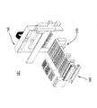
- a light guide gantry having two or more linkage portions provided with the leading ends of the light guide portions, and two or more connection ends provided with rear ends of the light guide portions provided with the leading ends of the linkage portions,
- a connection end array having an arrangement surface that is arranged and supported along a predetermined path, and is provided close to or in contact with the arrangement surface, and can be optically connected to each connection end sequentially along the predetermined path.
- a measuring instrument having one or two or more measuring ends and capable of receiving light based on an optical state in the reaction vessel by optical connection between the connecting end and the measuring end, and arranged in the connecting end array
- the connection ends and the measurement ends are relatively moved so as to optically connect in sequence. It is a direct acting type reaction device and a that light switching mechanism.
- the “optical state” is a state such as light emission, coloration, color change, or light change.
- the light based on the optical state is light generated by light emission or change, reflected light or transmitted light of light applied to coloration or color change, scattered light, or the like.
- the relative amount of each nucleic acid in a test that requires quantitativeness such as analysis of gene expression level
- SPIA Single Primer Isothermal Amplification
- a linear DNA amplification method by an isothermal reaction using a DNA / RNA chimera primer, DNA polymerase, and RNaseH is used.
- the real-time PCR method there are an intercalation method, a hybridization method, and an LUX method as methods that are usually performed using a fluorescent reagent containing a fluorescent substance.
- the “intercalation method” uses the property that fluorescent substances such as SYBR (registered trademark) GREEN I and ethidium bromide enter double-stranded DNA during the extension reaction and emit fluorescence when irradiated with excitation light. It is a method of measuring quantity. Therefore, the amplification solution contains at least the fluorescent substance and a quencher that suppresses light emission of the fluorescent substance.
- the “hybridization method” is a method of detecting only a target PCR product using a DNA probe labeled with a fluorescent substance in addition to a PCR primer. That is, the hybridized DNA (amount) is detected by hybridization of the fluorescently labeled DNA probe with the target PCR product.
- the “LUX method” utilizes the property that the fluorescence signal of a fluorescent substance labeled on an oligonucleic acid is influenced by the shape (sequence, single strand, double strand, etc.) of the oligonucleic acid.
- real-time PCR is performed using a PCR primer (LUX primer) labeled with one kind of fluorescent substance and a PCR primer not labeled with respect to it.
- the LUX primer has a fluorescent substance labeled near the 3 ′ end and is designed to take a hairpin structure with the 5 ′ end.
- the quenching effect is solved and the fluorescence signal increases. By measuring this signal increase, the amount of PCR product can be measured.
- the “linkage part” is a member that can be linked to the reaction vessel so that it can be released directly or indirectly via a sealing lid or the like.
- the linkage portion is provided with a light guide tip that is optically connected to the inside of the reaction vessel and can guide light based on the optical state in the reaction vessel.
- linkage with the reaction vessel means that it is close to or connected to the opening, outer wall, outer bottom of the reaction vessel, or the attached sealing lid or sheath, etc.
- the “connection” includes contact, close contact, close contact, fitting, and mounting, and includes optical contact with the light guide. At least contact so that a connection is possible. This is because the light guide portion provided in the linkage portion and the inside of the reaction vessel are optically connected by this linkage.
- the tip of the light guide part is a hole formed in the plate-like part, a translucent part such as an optical fiber, a lens or the like
- a translucent part such as an optical fiber, a lens or the like
- a cylindrical member or the like provided so as to protrude from the light guide pedestal, and the distal end of the light guide portion is a cavity provided in the cylindrical member or the like, a transparent fiber such as an optical fiber.
- It is an optical system element such as a light part or a lens.
- the flexible light guide is, for example, an optical fiber or an optical fiber bundle. When measuring fluorescence, it has two or more light guides, a part of which is used for irradiation and the other for receiving light.
- the reaction vessel is sealed with mineral oil or the like.
- the linkage portion directly connects the reaction vessel to the reaction vessel. It is preferable to form it so that it can be sealed.
- the reaction vessel or its linking portion needs to have translucency.
- the “predetermined path” is a path on a plane or curved surface that allows the measurement end and the connection end array to move relative to each other so that all the connection ends arranged along the measurement end can be scanned.
- the path connecting all the connection ends is a path along a single or multiple non-intersecting line segments (including zigzag lines and closed lines), curves (including spirals and closed curves), or combinations thereof.
- each single or multiple path is continuous and is along a straight line with no cusps or corners, or along a smooth curve with a curvature that can be traced by the measurement end.
- the linkage part and the connection end are provided in correspondence with each other, and in a case of one-to-one correspondence, a case of a plurality of one-to-one correspondence, and a case of a one-to-many correspondence. In the middle of this, it is possible to branch or merge the light guide sections, or to branch or merge the light guide section bundle composed of a plurality of light guide sections.
- the predetermined path is preferably determined so that smooth scanning is possible based on the number, shape, arrangement, or size of the measurement end of the measuring instrument. For example, in the movement of the connection end with respect to the measurement end, a predetermined path along a straight line that does not change abruptly, for example, an obtuse or perpendicular direction with respect to the traveling direction, is preferable.
- the arrangement pattern of the linking portion is, for example, a matrix, a column, or a row
- the arrangement pattern of the connection ends is, for example, the same arrangement, a similar arrangement that differs only in size, or a different arrangement pattern, for example, There may be a circular shape, other closed curve shapes, a single column shape, or a matrix shape having a smaller number of columns or rows.
- the predetermined path is determined so as to pass through all of the arranged connection ends.
- the arrangement of the connection ends is integrated with the arrangement of the linkage portions.
- the predetermined path (or the array pattern of the connection ends) is smaller or smaller than the area of the region surrounding the array pattern of the link portions of the light guide base or the interval between adjacent link portions. This is preferably done by reducing the total scanning distance.
- the speed is the same, it is possible to process in a shorter time than the case where the measurement end directly scans the linkage portion.
- the degree of integration is, for example, that the relative movement or scanning between the connection end array and the measuring device completes light reception from all reaction vessels to be measured within a stable light receiving time. It is preferable that it is possible.
- the “stable light receivable time” is a time during which the optical state capable of receiving light in the reaction container is stably maintained.
- the real-time PCR intercalation method, LUX method, or hybridization In the case of the TaqMan probe of the method, this corresponds to the time during which the extension reaction of each cycle of PCR is performed. In the case of using a FRET probe in the hybridization method, the time for annealing is equivalent to this.
- this stable light receiving time is, for example, about several seconds to 10 seconds.
- the amount of fluorescence detected is below the detection limit in the initial cycle of the PCR reaction, and the latter cycle of the PCR reaction is in a plateau state, and in order to ensure quantification in a strict sense, exponential PCR amplification is observed. This is within the range of the amplification curve that can be produced.
- the present invention makes use of the fact that the stable light reception time can be used as the movement time between the reaction vessels at the measurement end, and the relative movement necessary for receiving the light from each reaction vessel is represented by this stable light reception. Performing light reception from multiple reaction vessels within a possible time without using complicated optical elements and increasing the number of reaction vessels, or a number sufficiently smaller than the number of reaction vessels It can be performed almost in parallel by the vessel.
- connection end and the measurement end sequentially means that the connection end and the measurement end are optically connected by facing each other at a close distance. Since the moment of connection corresponds to the maximum value of the amount of light received by the measuring instrument, the measurement control unit specifies data to be measured by calculating the maximum value of the amount of light.
- the “measuring device” enables measurement of, for example, fluorescence and chemiluminescence. In the former case, irradiation of one or more types of excitation light, one or more types of wavelengths are performed. Fluorescent light reception and a filter for this purpose. These are preferably guided using an optical fiber.
- the “measurement end” has at least an incident port for light to be received provided in the measuring instrument, and has an exit port for light to be irradiated in the case of fluorescence measurement. These can be provided as separate measuring ends.
- the entrance or exit is optically connected to a light receiving unit or irradiation source made of a photoelectric element provided inside. In that case, it can each connect via the light guide part for light reception, or the light guide part for irradiation.
- the connection end array, the measurement end, and the measuring device are provided at positions that are not in direct contact with or close to a reaction vessel or a mounting base on which heating control or temperature control is performed.
- the linear motion reaction processing apparatus has a “measurement control unit” which is not explicitly described, and the “measurement control unit” controls the measuring device and the light guide switching mechanism, and A computer (CPU) built in the type reaction processing apparatus and a program for driving the computer. For example, measurement control is performed by sending a signal to each control unit for driving each moving mechanism through a DA converter. Become.
- the gantry moving mechanism described later uses at least a part of the dispensing head moving mechanism.
- the vertical movement mechanism for example, the nozzle Z-axis movement mechanism
- the gantry moving mechanism can move independently with respect to movement in the Z-axis direction. Is preferred (as the vertical movement mechanism of the gantry).
- At the time of light reception by the measuring device at least the inside of the measuring device excluding the measuring end is provided immovably with respect to the reaction vessel and the light guide frame having a linking portion linked thereto. It is a direct acting reaction processing apparatus.
- connection end array may move with respect to the measurement end, or the measurement end may move with respect to the connection end array, and the measuring instrument body is linked to the reaction vessel with the light guide base.
- the measuring instrument body is linked to the reaction vessel with the light guide base.
- it may be provided so as to be movable with respect to the reaction vessel or the light guide base.
- the measuring instrument main body is interlocked with the light guide base or when the measuring instrument main body is interlocked with movement in a part of the direction
- the measuring instrument main body is interlocked with the reaction container, or This is a case where the reaction vessel and the stage are fixed.
- the measurement end also includes a light guide portion that is outside the measuring instrument main body and extends to the measurement end if present.
- a tenth invention includes a gantry moving mechanism that moves the light guide gantry relative to the container group so that the linking portion is directly or indirectly linked to two or more reaction vessels at once. It is a direct acting reaction processing apparatus.
- the gantry moving mechanism presses the sealing lid mounted to cover the opening of the reaction container or Can be shaken. That is, it is preferable that the measurement control unit performs control so that the sealing lid is pressed or shaken after being indirectly linked with the linking portion via the sealing lid so as to cover the opening of the reaction vessel. .
- the reaction vessel can be securely sealed, and by shaking, the sealed state between the opening of the reaction vessel and the sealing lid can be quickly and easily released and opened. Therefore, high processing efficiency and reliability can be obtained.
- the linking part When the linking part is linked to the reaction container by being close to the reaction container, not directly or indirectly by connection such as fitting with the opening of the reaction container, the relative movement in the vertical direction By moving in the horizontal direction without performing the steps, the linkage between the linkage portion and the reaction vessel and the release thereof can be sequentially and smoothly repeated.
- two or more linking portions provided on the light guide pedestal can move in a horizontal direction with respect to the light guide pedestal in a state in which the two or more reaction vessels can be directly or indirectly linked together.
- the linkage between each linkage portion and the reaction vessel is extended in the horizontal direction in which each linkage portion can be inserted and the linkage portion array body is movable, and the light guide base is attached to each linkage portion. It is preferable to carry out in two or more grooves provided or in a shielded area shielded from each other such as two or more areas partitioned by a partition wall. Thereby, mixing of light from other reaction containers can be surely prevented.
- the linking part can be linked with the reaction vessel easily and at high speed only by moving in the horizontal direction without depending on the vertical movement of the light guide base. Accordingly, by setting the speed of the linking portion array so that it can be performed within the stable light receiving time including the horizontal movement of the linking portion array, one set of more reaction vessels can be obtained. With this measuring device, light reception and measurement can be performed substantially in parallel.
- the measuring instrument has one or two or more measuring ends that are optically connectable to the connecting ends, and a plurality of types of specific wavelength measurements capable of receiving light of a specific wavelength or a specific wavelength band And a measurement end alignment unit that aligns the plurality of measurement ends so as to be optically connectable to the connection ends along the predetermined path.
- the measuring device or each specific wavelength measuring device has an excitation light irradiation source for irradiating the corresponding excitation light and a light receiving unit.
- an irradiation port connected to the irradiation source and a light receiving port connected to the light receiving unit are provided as the same measurement end or separate measurement ends.
- an optical system element such as a cavity and a lens, and a light guide unit such as an optical fiber are provided.
- Measurement is performed integrally or in a chain. “Integrally” means that the measurement ends are arranged to be fixed to each other without any degree of freedom. “Chain” means that the measurement ends are arranged with a certain degree of freedom like a chain. In “alignment”, the measurement ends may be arranged along the scanning direction of the predetermined path or a direction perpendicular to the scanning direction. In the latter case, a plurality of paths are arranged in parallel as the predetermined path.
- a plurality of types of amplification targets can be amplified in parallel under the same conditions in one reaction vessel,
- multiplex PCR amplification or multiplex real-time PCR can be performed by using a primer labeled with a plurality of types of luminescent substances or the like.
- the reaction container and the liquid container are arranged in series, and the light-transmitting member that is attached to the opening of at least one of the reaction containers and seals the reaction container
- the upper side of the sealing lid is formed so as to be attachable to the dispensing head, and the sealing lid is attached to the opening of the reaction vessel by detaching the reaction sealing lid. It is a direct-acting reaction processing apparatus that can be mounted.
- the “sealing lid” includes not only a plate-like or block-like inflexible but also a flexible film-like or film-like one.
- the “mounting” includes fitting, screwing, friction, adsorption, adhesion, adhesion, and the like. In this case, it is preferable to detachably attach.
- each linking portion of the light guide base is linked at the opening of each reaction vessel, the linking portion or the nozzle is pressed or shaken against the sealing lid that covers the opening of the reaction vessel.
- the sealing lid that covers the opening of the reaction vessel.
- the linkage part is provided so as to protrude below the light guide base.
- the linkage portion has, for example, a rod shape, a cylindrical shape, a cone shape, or the like, and a lower end portion of the member can contact the sealing lid.
- One sealing lid covers one or more reaction container openings.
- the sealing lid is moved by being attached to a nozzle to be described later, and covers the opening of the reaction vessel using a chip detachment mechanism.
- one or more mounting recesses that can be mounted on one or more of the nozzles are provided on the upper side of the sealing lid.
- One or two or more of the linking portions can be inserted into the dent (which is also a dent for linking) by the vertical movement of the light guide base and linked to the reaction vessel.
- the linear reaction processing apparatus includes, for example, a transport body movable with respect to the container group, a covering plate that covers the opening of each reaction container, and the light transmissive body.
- a sealing lid having a mounting portion that protrudes downward at a portion excluding the central portion of the covering plate and that can mount the covering plate on the reaction vessel, and is exposed to the lower side in a state where the mounting portion can be mounted on the reaction vessel.
- the cover plate is gripped as described above, and has a hermetic lid transport body having one or more grip portions arranged on the transport body in accordance with the arrangement of the reaction containers. Further, if the hermetic lid carrier is interlocked with the light guide base, the structure of the apparatus can be simplified and the scale of the apparatus can be prevented from being increased.
- the linking portion reacts on the sealing lid without depending on the vertical movement of the light guide base. It can be easily linked only by moving horizontally between the openings of the container. In this case, if the linking portion can be moved in the horizontal direction within the time during which stable light reception is possible, light reception and measurement can be performed in parallel in a larger number of reaction vessels.
- the sealing lid is preferably provided at the same coordinate position in the series arrangement direction between the dedicated regions.
- the thirteenth aspect of the present invention is a direct acting reaction processing apparatus in which the light guide base has a heating unit capable of heating the sealing lid.
- the measurement control unit controls the gantry moving mechanism so that the optical linking unit is indirectly linked to two or more reaction vessels simultaneously after the sealing lids are attached to the linking unit all at once. Thereafter, the heating unit is controlled to heat the sealing lid.
- the “heating unit” has a heating function at a temperature set by, for example, the magnitude of an applied current or based on on / off control.
- the heating of the sealing lid by the heating unit is performed to prevent condensation during temperature control of the reaction vessel sealed by the sealing lid.
- a fourteenth aspect of the invention includes a temperature controller having a temperature source provided in contact with or close to a lower wall portion of the reaction vessel, and an upper portion of the reaction vessel positioned above the lower wall portion of the reaction vessel. And a heating unit having a heating source provided in contact with or close to the side wall portion and capable of heating the upper side wall portion.
- the “lower wall portion” refers to a wall portion including a bottom portion or a part of the wall portion that surrounds a volume portion that can accommodate a predetermined amount of a predetermined amount of liquid (for example, 1% to 90%) of the total volume of the reaction vessel. Part.
- the lower wall portion is, for example, a wall portion of a portion that can accommodate the liquid of the specified liquid amount.
- a reaction vessel composed of a wide-mouthed pipe part and a narrow-mouthed pipe part linked to the linkage part, it is provided in the narrow-mouthed pipe part.
- the “upper wall portion” is a container portion that surrounds the remaining volume of the lower container portion in which the specified liquid amount is accommodated, or a part thereof, out of the total capacity of the reaction vessel.
- the “upper wall portion” is usually preferably provided on the upper side of the reaction vessel spaced from the lower wall portion.
- the upper wall portion is closer to the opening, the sealing lid, or the linkage portion than the lower wall portion.
- an upper wall portion is provided on the wall portion of the wide-mouthed tube portion.
- the upper side wall portion is, for example, a portion corresponding to a strip shape along the circumference of the container wall.
- the measurement control unit controls the gantry moving mechanism so that the linking unit is directly or indirectly linked to the reaction vessel at once, and then prevents the linking unit from directly or indirectly condensing.
- Control the heating section “Indirect linkage” refers to the case where the linkage portion is linked to the reaction vessel via a sealing lid, the outer wall of the reaction vessel, or the like.
- “Control of the heating unit” is performed according to “temperature control” in order to prevent condensation.
- the heating temperature is several degrees (a temperature exceeding the dew point of water vapor necessary for preventing condensation) to several tens of degrees Celsius (the melting point of the material in the reaction vessel) is sufficiently lower than each predetermined temperature set by temperature control. Temperature), for example, 1 ° C.
- heating is performed at a temperature higher than 94 ° C., for example, 100 ° C., and when isothermal is used, when the predetermined temperature is about 55 ° C., for example, several degrees higher than that. Heating is performed at a high temperature, for example, about 60 ° C to 70 ° C.
- the heating unit directly heats the reaction vessel instead of the linkage unit or the sealed unit, thereby reducing the thermal effect on the optical system element provided in the linkage unit or the measurement end near the linkage unit or
- the reliability of the image obtained through the optical system element can be improved.
- various lenses such as a ball lens and an aspherical lens, which are the optical system elements, in the linking part, the light generated in the reaction container and emitted in the direction of the opening is reliably condensed to an optical fiber.
- the light can be incident on a light guide unit such as a light guide.
- a reaction vessel a temperature controller having a temperature source provided in contact with or in proximity to the lower wall portion of the reaction vessel, and controlling the temperature in the reaction vessel, and contacting the upper wall portion or
- a heating unit that is provided in the vicinity and has a heating source capable of heating the upper side wall portion constitutes a reaction vessel control system.
- the reaction vessel includes a wide-mouthed pipe part and a narrow-mouthed pipe part provided below the wide-mouthed pipe part and communicating with the wide-mouthed pipe part and formed narrower than the wide-mouthed pipe part.
- the portion can be fitted with the tip of the linkage portion, and the narrow mouth tube portion can contain liquid, the lower wall portion is provided in the narrow mouth tube portion, and the upper wall portion is provided in the wide mouth tube portion. It is preferred that Moreover, it is preferable that the contact surface between the upper part of the reaction vessel heated by the heating part or the sealing lid contacting the reaction container and the linkage part is as small as possible. As a result, the influence of the link portion on the optical system element by the heating portion can be reduced or eliminated.
- a tip of a light guide part bundle made up of a plurality of light guide parts is provided in each linkage part, and a rear end of a part of the light guide part bundle of the light guide part bundle is a first end of the connection end array.
- the remaining part or all of the light guide section bundle is provided at the second connection end of the connection end array, and the predetermined path includes the first path and the second path.
- the first measurement end provided in the measuring device is moved along the first path formed by the first connection end by moving the connection end array, and the second measurement end is It is a direct-acting reaction processing apparatus that moves relatively along a second path composed of a second connection end.
- the first measurement end is optically connected to the light receiving unit of the measuring instrument, and the second measurement end is connected to an irradiation source of the measuring instrument and corresponds to the first connection end.
- the tip and the tip corresponding to the second connection end are arranged so as to coexist, the first measurement end is connectable to the first connection end, and the second measurement end is It is a direct acting reaction processing apparatus connectable with the second connection end.
- the “mixing of the tips” is preferably arranged so that the tips of two or more light guides are mixed so that they are homogenized.
- specimen information for identifying or managing a sample and examination information indicating examination contents are visually displayed in each dedicated area, and each dedicated area including the specimen information and the examination information is displayed.
- a digital camera that captures displayed contents and obtains image data is a linear motion reaction processing apparatus provided in the crossing head.
- specimen information is information necessary for identifying or managing a sample.
- information for identifying a sample include a patient, animal, foodstuff, soil, sewage from which the sample was collected.
- Sample attributes such as patient name, age, gender, ID number, food sales location, soil collection location, collection date and time, or sample physical properties such as patient blood, urine, feces , Body fluid, cell type, food type, soil type, sewage type, and the like.
- the information for managing the sample includes, for example, a sampler of the sample, a collection date, a person in charge of inspection for the sample, a date of inspection for the sample, and the like.
- Test information is information indicating the content of a test performed on a sample.
- test items for example, various gene information (for example, SNPs, nucleotide sequence determination), genetic diagnosis, or other various proteins Information or the type of reagent used in the test, the reagent production lot number, the calibration curve of the reagent, or the type, structure, type of biological substance fixed on the carrier, etc. can be contained.
- Such information is displayed in the case of handwriting, printing, bar code, or QR (registered trademark) code (matrix two-dimensional code).
- QR registered trademark
- the ultrasonic vibrator moves relatively between an ultrasonic vibrator having an ultrasonic vibrator and a horn that resonates with the ultrasonic vibrator, and the ultrasonic vibrator and the sample container.
- a direct-acting reaction processing apparatus that includes an oscillating portion moving mechanism that enables the sample housing portion to be pressed by the horn to apply ultrasonic vibration.
- the vibration part moving mechanism it is preferable to further include an advance / retreat operation mechanism that enables the horn to advance / retreat with respect to the outward direction of the ultrasonic vibration part.
- the said horn or the said sample accommodating part is supported so that it may be elastically biased along the said outer direction.
- At least one reaction container and two or more liquid storage units are arranged in series in at least one row as a container group, and one or two or more dispensing tips can be attached to and detached from the dispensing head.
- the dispensing head is moved relative to the container group along a series arrangement direction, and at least one of the liquid containing portions is used as a sample containing portion, and the dispensing tip is provided in the sample containing portion.
- the sample suspension is stored using, the sample storage portion is subjected to ultrasonic vibration, and each of the sample suspensions is arranged in series using the dispensing tip. Or it is the direct acting type reaction processing method which transfers to the said reaction container along the serial arrangement
- the sample suspension in the sample storage unit In order to store the sample suspension in the sample storage unit, for example, it is sucked and transferred by the dispensing head from another container in which the parent specimen is stored, and the tip is inserted into the sample storage unit. This is done by discharging. It is preferable that the dispensing head is provided with the magnetic part, and that the magnetic particle suspension is accommodated in a part of the liquid accommodating part when the target substance is separated and extracted. . Further, it is preferable that a common area is provided in the container group, a crossing head is advanced into the common area, and the tip of the dispensing tip is inserted into at least one liquid container provided in the common area.
- each dedicated region is equipped with at least one reaction vessel, two or more liquid storage units for storing a solution necessary for processing and a magnetic particle suspension, and one or more dispensing tips.
- One or two or more tip accommodating portions that can be accommodated are arranged in series, and each set of dispensing tips is detachably attached to the dispensing head, and the dispensing head is dedicated to each The tip of the dispensing tip is moved all at once in the region along the series arrangement direction, and the tip of the dispensing tip is moved to any one of the reaction container, the liquid container, or the chip container in each dedicated region. Insert and perform suction or discharge of liquid through the tip.
- sample receiving portion at least one of the liquid storage portion in the use region is direct-acting reaction treatment method of applying ultrasonic vibration. Therefore, before the ultrasonic vibration is applied, the sample suspension is discharged and stored in the sample storage portion through the tip portion thereof by the dispensing tip.
- At least one liquid storage portion and one or more tip storage portions that can be stored so that one or more dispensing tips can be mounted outside the dedicated area.
- each scattering prevention plug stored in a position along the series arrangement direction is attached to the dispensing head.
- a direct acting reaction process in which each of the sample storage portions is ultrasonically vibrated after the stoppers are attached and closed to the openings of the sample storage portions, and the plugs are detached from the dispensing head. Is the method.
- the anti-scattering stoppers are arranged along the series arrangement direction together with the sample container, the reaction container, and the liquid container.
- the splicing prevention plug is perforated by attaching a drilling tip accommodated in a position along the serial arrangement direction to the dispensing head. Then, after removing the perforating tip, the sample is attached to the dispensing head, and the crushed sample is sucked, moved to the liquid container, and discharged, for example, by the magnetic particles. The magnetic particle suspension is sucked by the dispensing tip, moved to the next liquid storage portion along the serial arrangement direction, and discharged.
- a target substance is extracted using a sample suspension accommodated in each sample container to which ultrasonic vibration is applied, and the target substance is moved along a serial arrangement direction, Two or more linking parts housed in each of the two or more reaction containers provided in the container group, and provided with one or more flexible light guides for each reaction container.
- the reaction vessel and the linkage portion are linked together directly or indirectly, optically connecting the linked reaction vessel interior and the light guide portion, Temperature control is performed in the reaction vessel, and light from the reaction vessel is passed along a predetermined path through two or more connection ends provided with a rear end of the light guide portion provided with a tip of the linkage portion.
- connection end array having an array surface to be arranged and supported, and approach or contact the array surface
- One or two or more measurement ends provided in the measuring instrument and the respective connection ends are moved relative to each other so as to be optically connected sequentially along the predetermined path.
- the measuring device has a plurality of types of specific wavelength measuring devices capable of receiving light of a specific wavelength or a specific wavelength band, and each specific wavelength measuring device is sequentially provided along each connection end and the predetermined path. And at least one measurement end that can be optically connected, and each of the plurality of measurement ends is aligned by a measurement end alignment unit, and each of the measurement ends is sequentially optically connected to each of the connection ends along the path.
- each specific wavelength measuring device is a direct acting reaction processing method in which light of a specific wavelength or a specific wavelength band based on the optical state in the reaction container is received.
- the light guide base is attached to the reaction container after two or more sealing lids arranged in the container group and having translucency that can be fitted to the opening of the reaction container are attached to the reaction container all at once.
- a direct-acting reaction treatment method in which each of the sealing lids is moved is preferable.
- a direct acting reaction treatment method in which the sealing lid covering the opening of the reaction vessel is pressed or shaken is preferable. Therefore, it is possible to ensure the sealing of the reaction vessel by controlling to press the sealing lid that covers the opening of the reaction vessel. Moreover, by shaking the sealing lid, the sealed state between the opening of the reaction vessel and the sealing lid can be quickly and easily released and opened. Therefore, high processing efficiency and reliability can be obtained.
- the temperature in the reaction vessel when controlling the temperature in the reaction vessel by directly or indirectly linking the opening of the reaction vessel and the linking portion, it is provided in contact with or close to the lower wall portion of the reaction vessel.
- the heating unit provided on the upper wall portion of the reaction vessel located above the lower wall portion in contact with or close to the upper wall portion It is also possible to prevent direct or indirect dew condensation of the linkage part by heating with a heating source.
- a dispensing tip is detachably attached to the dispensing head, and is moved in a series arrangement direction between the dispensing head and the container group, so that it is in series with the container group.
- a guide for light guide provided on the dispensing head and having two or more linking portions provided with one or more light guides at the tip thereof, and moved together with the dispensing head on the way, the reaction vessel and the Directly or indirectly with linkage
- the reaction vessel interior and the light guide unit are optically connected to each other, temperature control is performed in the reaction vessel, and light from the reaction vessel is associated with each linkage unit.
- connection ends provided with the rear end of the light guide portion provided at the front end of the linkage portion are guided along a predetermined path and led to a connection end array body, By sequentially moving one or more measurement ends provided on the measuring surface and the respective connection ends, which are provided close to or in contact with the arrangement surface, and sequentially optically along the predetermined path. It is a direct acting reaction processing method in which the measuring device receives light based on the optical state in the reaction vessel by being connected.
- the sample container in the step of applying ultrasonic vibration to the sample container, is relatively moved between an ultrasonic vibrator having an ultrasonic vibrator and a horn that resonates with the vibration, and the sample container.
- the direct acting reaction processing method of applying ultrasonic vibration by pressing the sample storage portion with the horn It is preferable that the horn moves forward along the outer direction from the ultrasonic vibration unit approaching the sample storage unit and presses the sample storage unit. “Approaching” means, for example, that the tip of the horn approaches the forward reach distance of the horn with respect to the bottom or side surface of the sample container.
- the said horn or the said sample accommodating part is supported so that it may be elastically biased along the said outer direction.
- the sample container is preferably supported so as not to move in the outer direction (16th invention). But the same).
- the dispensing heads are arranged in series by arranging the reaction vessel, liquid container, and sample container used for processing in series.
- processing including preprocessing can be executed consistently, so the movement path of the dispensing tip is simplified and easy to control, and the movement distance is the shortest.
- Processing including processing can be performed quickly and efficiently.
- the burden on the user can be reduced.
- the movement path is simplified, and cross contamination can be reliably prevented by separating the movement paths from one another for each sample.
- ultrasonic vibration to the sample, extraction of a target substance obtained from the sample, homogenization and suspension of the sample can be promoted. Then, the subsequent reaction is promoted, and the processing can be speeded up and made efficient. Moreover, the reliability of processing can be improved.
- a dedicated area is set, and in one or more dedicated areas corresponding to each set in which one set of the dispensing tips enters and the other set of dispensing tips does not enter
- the movement of each set of dispensing tips is limited to movement along the series arrangement direction, thereby cross-contamination between dedicated areas.
- National can be reliably prevented.
- separation means including means necessary for pre-processing in each dedicated area, it is possible to consistently execute the process within each dedicated area, thus preventing cross contamination more reliably. It is.
- the third aspect or the nineteenth aspect by preliminarily prepacking the liquid containing portions provided in a plurality of dedicated areas by providing a crossing head that is relatively movable so as to cross all the dedicated areas.
- Common reagents that are not suitable for use for example, reagents that require heating or cooling, reagents that easily deteriorate, etc. are stored and supplied to the liquid storage unit, or products generated in each dedicated area It is suitable for storing and preserving products and results in an area separate from the dedicated area.
- the liquid storage part is a prepack storage part that has been previously stored with a liquid or magnetic particle suspension necessary for processing and sealed with a pierceable film. If this is the case, dispense processing into an empty liquid container is not required, and a perforation tip positioned in the serial arrangement direction is attached to the dispensing head for perforation, and desorption is performed and a dispensing tip is attached. By doing so, it is possible to perform a quick and reliable process.
- the ultrasonic vibration is prevented from propagating to other than the sample storage unit to which the ultrasonic vibration is to be applied. Vibration can be efficiently applied to the sample storage portion.
- the opening part is obstruct
- the jumping out of the sample in vibration is prevented,
- the sample by a sample Contamination outside the housing portion can be prevented.
- the stopper can be perforated and sucked out with a dispensing tip, so that the user does not have to open the stopper, reducing the burden on the user and contaminating the user. Can be prevented. Further, since it is not necessary to attach the stopper in a detachable state, it can be securely attached so that it does not come off due to vibration or the like, and it is safe.
- the anti-scattering plug for sealing the sample accommodating portion is attached to the sample accommodating portion by fitting, and the upper side of the anti-scattering plug can be attached to the dispensing head. ing.
- the scattering prevention plugs are arranged along the series arrangement direction together with the reaction container and the liquid storage portion. Therefore, by combining the movement of the dispensing head along the series arrangement direction, the sample storage portion can be easily sealed with the anti-scattering stopper.
- the plurality of reaction vessels are linked to each other by the linkage portion provided on the light guide base and optically connected to the inside of the reaction vessel to guide the plurality of reaction vessels.
- a signal based on the optical state in the reaction vessel is transmitted to the connection end of the array surface of the connection end array through the optical mount and the light guide, and along a predetermined path on the array surface of the connection end array
- the connecting ends arranged in this manner and the measuring end of the measuring device are optically connected in sequence.
- the distance between the entire connection end arrangement region or the adjacent connection ends is made smaller than the arrangement region of the linkage part or the adjacent distance. This can be achieved by integration or by smoothing the movement of the measurement end by linearizing a predetermined path or enlarging the radius of curvature as compared with the arrangement of the linking portions.
- the structure of the optical system can be simplified.
- the connection end, measurement end, and measuring instrument away from the reaction vessel and light guide base where temperature control and heating control are performed the thermal influence of the optical elements is eliminated and reliable processing is performed. Can do.
- the movement of the connection end with respect to the measurement end includes continuous or intermittent movement.
- an amplification curve can be prepared and used for various analyzes such as determination of the initial concentration of DNA.
- the measuring device moves the reaction vessel and the light guide base linked to the reaction vessel. Therefore, during measurement, the optical system elements and electronic system elements built in the measuring instrument body are not subjected to inertial force due to acceleration caused by movement, etc. System elements can be prevented from being destroyed and highly reliable and precise measurement can be performed. In cases other than measurement, the measuring instrument main body can be moved with respect to the reaction container or the like, so that the measuring instrument can be carried near the reaction container for measurement.
- the linking portion can be linked directly or indirectly to the reaction vessels all at once without manual intervention. Therefore, cross contamination can be prevented and processing can be performed efficiently.
- a plurality of types of luminescent materials, color developing materials, color changing materials or photochromic materials in one reaction vessel for example, a plurality of types of amplification targets can be Multiplex PCR amplification and multiplex real-time PCR can be performed for multiple types of amplification targets by using primers labeled with multiple types of luminescent substances, etc. It is.
- a mechanism for switching the reception of light of a plurality of types of specific wavelengths or a specific wavelength band from a plurality of types of luminescent substances, etc., when moving between a plurality of reaction vessels using a stable light reception time By using both, it is not necessary to separately provide a special light switching mechanism, the apparatus mechanism can be simplified, and the manufacturing cost can be reduced. Furthermore, since each specific wavelength measuring device receives light of a single specific wavelength or specific wavelength band, it is possible to perform high-precision measurement without being affected by other specific wavelengths or specific wavelength bands. it can. In addition, since each specific wavelength measuring device can be modularized for removal and addition, highly versatile processing according to the processing purpose can be performed.
- the sealing lids arranged in the container group can be attached to the opening of the reaction container by moving the dispensing head or the like by attaching the sealing lid to the linkage part or the nozzle. Since it is possible, the contents in the reaction container do not directly contact the linking part of the gantry, so that cross contamination can be effectively prevented. Moreover, since it is not necessary to provide a dedicated mechanism for mounting the hermetic lid on the reaction vessel, the scale of the apparatus is not increased and the manufacturing cost is reduced.
- direct or indirect dew condensation on the linkage portion can be prevented by heating the upper wall portion of the reaction vessel according to the temperature control of the lower wall portion of the reaction vessel. .
- the heating is performed on the upper side wall portion of the reaction vessel, not directly on the linkage portion or the sealing lid, direct heating to the optical system element provided on the linkage portion is performed. Can be reduced or eliminated.
- image distortion and the like due to deterioration and alteration of the optical system elements can be reduced or removed, and various optical system elements can be provided in the linking portion, so that accurate and versatile measurement can be performed.
- information is displayed in each dedicated area, and the information displayed in each dedicated area is read by the camera as the traversable nozzle moves, so that the reliability can be increased without increasing the scale of the apparatus.
- a highly reactive reaction and measurement process can be performed.
- the number of parts such as an ultrasonic vibrator and a horn is reduced because the plurality of sample storage parts and at least one ultrasonic vibration part are relatively moved.
- the device structure can be simplified and the manufacturing cost of the device can be reduced.
- the ultrasonic vibrator applies vibration to the object inside the sample container, there is no direct contact with the object and there is little risk of cross contamination.
- FIG. 1 is an overall block diagram showing a direct acting reaction processing apparatus according to a first embodiment of the present invention.
- 1 is an overall perspective view showing an example of a direct acting reaction processing apparatus according to a first embodiment.
- FIG. 3 is a plan view of the direct acting reaction processing apparatus shown in FIG. 2. It is a perspective view which expands and shows a part of ultrasonic vibrator shown in FIG. It is an enlarged view of the sample storage part shown in FIG. 2, FIG. It is a figure which shows the sample accommodating part which concerns on another Example. It is a graph which shows the experimental result of the ultrasonic vibration process using the linear motion type reaction processing apparatus shown in FIG. It is a whole block diagram which shows the direct acting type reaction processing apparatus which concerns on the 2nd Embodiment of this invention.
- FIG. 10 is an overall perspective view showing the direct acting reaction processing apparatus of FIG. 9 from the back side.
- FIG. 10 is a plan view of the direct acting reaction processing apparatus shown in FIG. 9.
- FIG. 10 is an enlarged cross-sectional view showing a measurement end of the linear motion reaction processing apparatus shown in FIG. 9.
- It is a whole perspective view which shows the direct-acting type reaction processing apparatus which concerns on the 3rd Embodiment of this invention.
- FIG. 1 shows a block diagram of a direct acting reaction processing apparatus 10 according to a first embodiment of the present invention.
- the sequence portion 70 and the a movable so as to cross the entire dedicated area 20 i, the exclusive region 20 i and the common region 20 0 possible its distal end to the liquid containing portion is provided inserted into a separatory
- the dispensing head 50 having a crossable nozzles 71 0 of one for removably attaching the tip 211 0, the dispensing provided on the head 50 each minute is attached to the nozzle array section 70 dispensing tip 211 i A magnetic part 57 that exerts a magnetic field .
- the crossable nozzles 71 0 corresponds to an example of the "cross-head".
- the direct-acting reaction processing apparatus 10 further includes a dispensing head moving mechanism 51 as a “series moving mechanism” that allows the dispensing head 50 to move along the Y-axis direction that is a series arrangement direction.
- ultrasonic vibration for applying the temperature controller 29 for controlling the temperature of each exclusive area 20 i reactor group 23 within i, ultrasonic vibration to the sample receiving unit 22 i in each dedicated region 20 i
- An ultrasonic vibrator 80 for controlling the child a CPU + ROM 60 including a CPU, a ROM, a RAM, various memories, a communication function such as a LAN, a program stored in the ROM, etc., and a display unit and an operation such as a liquid crystal display And an operation panel 13 having an operation unit such as a key and a touch panel.
- the dispensing head 50 further includes a nozzle Z-axis moving mechanism 75 as a “vertical moving mechanism” that allows the nozzle array unit 70 to move in the Z-axis with respect to the container group 20, and the nozzle 71 i .
- a suction / discharge mechanism 53 that enables suction and discharge of liquid with respect to the dispensing tip 211 i mounted on the nozzle 71 i by performing gas suction and discharge on the nozzle 71 i, and is detachably mounted on the nozzle 71 i.
- dispensing tip 211 i chip detaching mechanism 59 can be desorbed, liquid to the dispensing tip 211 0 attached to the nozzle 71 0 by performing suction and discharge of gas with respect to the crossable nozzle 71 0 a suction and discharge mechanism 53 0 to enable the suction and discharge, the movable crossable nozzle 71 0 relative to the X-axis direction and the Z-axis direction perpendicular to the series-like arrangement direction (Y-axis direction) With a crossable nozzle XZ axis moving mechanism 75 that includes a digital camera 19 provided on the crossable nozzle 71 0, the.
- the CPU + program 60 gives instructions for a series of processing such as extraction (including ultrasonic crushing), amplification, and sealing of the amplification solution for the nucleic acid or a fragment thereof, the temperature controller 29, the dispensing head moving mechanism. 51, tip detachment mechanism 59, suction / discharge mechanism 53, magnetic force part 57, nozzle Z-axis moving mechanism 75, ultrasonic vibrator 80, traversable nozzle 71 0 , camera 19, traversable nozzle XZ-axis moving mechanism 75 0 , suction / discharge made to the mechanism 53 0.
- the container group 20, 1 (in this example, one set corresponding to 1) a plurality (in this example nozzles 70 i enters another nozzle 70 K (k ⁇ i) are corresponding to each nozzle 70 i that does not enter the 12) dedicated areas 20 i and common areas 20 0 .
- a liquid storage section group 27 i composed of a plurality of storage sections that can store or store reagents, etc., and a plurality of dispensing tips 211 i and samples that are detachably attached to the nozzles 70 i.
- a chip storage section group 21 i for storing the chip and the like.
- the liquid container group 27 i includes at least one liquid container that stores at least a magnetic particle suspension, two or more liquids that store a nucleic acid or a fragment thereof, and a separation and extraction solution used for the extraction. 2 or more liquid storage units for storing an amplification solution used for nucleic acid amplification, and if necessary, a sealing solution for sealing in the PCR tube 231 i as the reaction container A liquid storage portion. Further, each dedicated region 20 i is directly or indirectly in contact with an ultrasonic transducer controlled by the ultrasonic vibrator 80, and a sample storage unit 22 i as a liquid storage unit to which ultrasonic vibration is applied. have.
- the common region 20 0, the provided outside only area 20 i, in the crossable nozzles 70 0 to detachably loaded dispensing tip 211 0 tip can pass region of the said transverse head there are, having a distal end insertable reagent etc. storage unit group 27 0, the chip housing portion group 21 0 for accommodating the dispensing tip 211 0 which is detachably attached to the crossable nozzle 70 0 . Then the reagents contained in the reagent etc. storage unit group 27 0 with crossable nozzle 70 0 transported and supplied to the dedicated area 20 i, or the product or products contained in the dedicated area it is possible to transfer and accommodated in the reagent etc. storage unit group 27 0. In addition, a solution such as DNA contained in a certain dedicated area 20 i can be dispensed and delivered to another dedicated area 20 K (k ⁇ i).
- FIG. 2 is an overall perspective view of the direct acting reaction processing apparatus 10 according to the embodiment of the present invention.
- the linear reaction processing apparatus 10 has a size of about 600 mm in length (Y-axis direction), width (X-axis direction), and height (Z-axis direction), for example.
- a dispensing head 50 that is movable in a series arrangement direction (Y-axis direction) with respect to the container group 20, a dispensing head moving mechanism 51 that moves the dispensing head 50 in the Y-axis direction, and temperature control
- a vessel 29 and an ultrasonic vibrator 80 are provided on the stage.
- the operation panel 13 and the CPU + program 60 are attached to a housing (not shown) in which the container group 20 and the dispensing head 50 are stored.
- the dispensing head 50 includes a base body 501 provided to be movable in a series arrangement direction (Y-axis direction), and twelve pieces provided to be movable in the vertical direction (Z-axis direction) with respect to the base body 501.
- Nozzles 71 i arranged in the X-axis direction at a predetermined pitch (for example, 18 mm), twelve dispensing tips 211 i attached to the nozzles 71 i , and a transverse direction (X-axis direction) ) dispensing tip 211 0 of one movable are those having a crossable nozzle 71 0 attached to.
- the dispensing head moving mechanism 51 includes a Y-axis moving motor 511 and a Y-axis moving frame 512 that can move along the Y-axis direction by a ball screw or a timing belt driven by the Y-axis moving motor 511.
- a base body 501 of the dispensing head 50 is supported by the Y-axis moving frame 512, supports the nozzle array part 70 so as to be movable in the Z-axis direction, and moves the nozzle array part 70 in the Z-axis direction.
- a Z-axis moving motor 751 is provided.
- a cylinder and nozzles communicating with the cylinder are supported so as to be arranged at the pitch below, and in order to perform suction and discharge of gas to the nozzle, the inside of the cylinder communicating with the nozzle
- a built-in cylinder drive plate for driving 12 plungers that can slide in the vertical direction and a motor 531 for suction and discharge drive for driving the cylinder drive plate are provided.
- a tip detaching member is provided below the nozzle array portion 70, and the tip detachment member is horizontally supported by the nozzle array portion 70 by two shafts that are movable downward while being urged upward, and a cylinder.
- the upper end of the shaft is located below the lower limit position of the normal suction / discharge vertical movement range of the cylinder drive plate.
- the cylinder drive plate exceeds the vertical range and descends to near the upper end of the cylinder, the shaft is pushed downward, and by descending to near the upper end of the cylinder, the chip detachment member is pushed downward.
- a tip detachment mechanism 59 is provided for lowering.
- twelve holes having an inner diameter that is larger than the outer diameter of the nozzle but smaller than the mounting portion that is the maximum outer diameter of the dispensing tip 211 i pass through the nozzle 71 i. The pitch is provided.
- the magnetic unit 57, the dispensing tip 211 i small-diameter portion 211 i a have a separable therefrom provided magnetic field to the dispensing tip 211 within the i with respect and twelve magnet that can be removed in 571 is provided on a movable body 572 movable along the Y-axis direction.
- Reference numeral 211 i c is the tip of the dispensing tip 211 i
- reference numeral 211 i b is the large-diameter portion.
- the ultrasonic vibrator 80 As shown in FIG. 2 or FIG. 3, on the stage, in addition to the dispensing head 50, as the container group 20, and the common area 20 0, and each dedicated region 20 i, the ultrasonic vibrator 80 A temperature controller 29 is provided.
- the common area 20 0, reagent etc. storage unit group 27 0 consisting of microplates having wells 270 0 8 rows ⁇ 12 columns, four rows ⁇ 6 columns mounted capable received in said transverse enable nozzle 71 0 dispensing chip accommodating portion group 21 0 for accommodating the chips, the plate in which the notch 591 0 to desorb the dispensing tip 211 0 mounted on crossable nozzle 71 0 from the nozzle 71 0 is formed of and a dispensing tip detaching part 59 0 with.
- reaction vessels or cartridge containers 24 i in which various accommodating portions are arranged in series and cartridge containers 28 in which four various accommodating portions are arranged in series.
- the parent specimen tube 26 i , and the sample accommodation section 221 i to which ultrasonic vibration can be applied are parallel to each other along the serial arrangement direction, and the same kind of accommodation section and reaction container, for the parent specimen
- the tubes are arranged so as to be in the same position with respect to the series arrangement direction (Y-axis direction).
- the cartridge container 24 i accommodates two reaction containers 23 i having different capacities, ten pre-packs or empty liquid storage unit groups 27 i , and two dispensing tips 211 i and 212 i .
- a chip housing group 210 i is provided.
- the cartridge container 28 i is provided with an accommodating portion for accommodating the two anti-scattering stoppers 221 ia and an accommodating portion for accommodating the punching chips 213 i and 214 i .
- the ultrasonic vibrator 80 resonates with the vibration of the ultrasonic vibrator and is pressed against each bottom part of each sample storage part 221 i and a plurality of (in this example, 12) horns 81 i and a plurality ( Twelve in this example) a vibration source built-in portion 81 in which the ultrasonic transducer is built in, and a plurality of (in this example, twelve) holding holes for holding the sample storage portion 221 i.
- a sample storage unit support 82 provided so as not to be in direct contact with the horn 81 i or the ultrasonic transducer.
- the vibration source built-in portion 81 is provided with a spring that elastically urges the ultrasonic transducer and the horn upward in order to press the horn 81 i against each bottom portion of the sample storage portion 221 i . . Moreover, the sample receiving portion supporting table 82, the sample accommodating unit 221 i so as not jump out the sample accommodating unit 221 i upward after is held by a flange 221d which will be described later, for example, slide horizontally A detachable slide-type pressing plate (not shown) is attached to the upper side of the sample storage unit support 82.
- FIGS. 5A, 5B, 5C, and 5D show the sample storage portion 221 in detail.
- the sample storage unit 221 includes a main body 221b of the storage unit, an anti-slip 221c formed on the outer surface on the upper side of the main body, an opening 221m, and a fitting portion 221i that fits on an edge of the opening 221m.
- an outer peripheral protrusion 221l formed on the outer periphery in the vicinity of 221m.
- the anti-scattering plug 221a further includes a pierceable film 221g formed so as to partition the upper side of the fitting portion 221i, and an inner portion protruding inward along the inner periphery at the edge of the plug 221a.
- a protrusion 221e which is used for detachment from the nozzle 71 using the tip detachment mechanism.
- FIG. 5 (e) and 5 (f) show a sample container 222 according to another embodiment, and the main parts corresponding to the respective parts of the sample container 221 are indicated by the same alphabet. The description is omitted.
- the structural difference between the sample storage unit 222 and the sample storage unit 221 is that an O-ring 222j is provided on the anti-scattering stopper 222a of the sample storage unit 222 to improve the sealing performance.
- FIG. 6 shows sample storage portions 223 and 224 according to another embodiment.
- the sample storage portions 223 and 224 are different from the sample storage portions 221 and 222 shown in FIG. 5 in that the scattering prevention plugs 223a and 224a are attached not by fitting but by screwing.
- the portions corresponding to the sample storage portions 221 and 222 in FIG. 5 are indicated by the same alphabet, and the fitting portions 221i and 222i provided with the inner peripheral protrusions 221k and 222k and the outer peripheral protrusions 221l and 222l are shown. Instead, screwing portions 223p and 224p provided with screw threads 223n and 224n are provided.
- step S1 the start of the separation and extraction process is instructed by operating the touch panel of the operation panel 13 or the like.
- step S2 the extraction control unit 61 provided in the CPU + program 60 of the direct acting reaction processing apparatus 10 instructs the dispensing head moving mechanism 51 to provide the dispensing head 50 and the dispensing head. It is moved to the crossable nozzle 71 in the X-axis direction provided on the (orthogonal series shaped arrangement direction and in a horizontal plane), the common region 20 0 of the chip accommodation portion 21 0, 1 dispensing tip 211 0 above the after located, to attach the dispensing tip 211 0 to the nozzle by lowering the nozzle 71 0. Then, positioned in the reagent etc.
- the storage unit group 27 0 microplates move the dispensing tip 211 0 mounted, water, various washings, the tip into the well 270 0 containing the various reagents A part is inserted, aspirated and then lifted, and dispensed into the corresponding accommodating part of each of the dedicated areas 20 i to remove various cleaning liquids and various reagents, except for the liquid accommodating part in which reagents and the like are pre-packed Supply to the storage. For example, different amounts of water are added to the parent specimen tube 26 i in which a sample suspension to be examined that is insufficiently quantified is previously stored, and quantified.
- step S3 the dispensing head 50 is moved along the Y-axis direction (in-line arrangement direction), and above the punching chip 213 i accommodated in the chip accommodating part 21 i of the cartridge container 28 i.
- the drilling tip 213 i is mounted by descending after being positioned at the position, and the drilling tip 213 mounted on the nozzle 71 i above the first liquid storage unit of the liquid storage unit group 27 i of the container group 20.
- step S4 the move to the cartridge container 28 i, after detaching the drilling tip 213 i to the original receptacle, the cartridge receptacle 24 i of chips to respective nozzles 71 i along the Y-axis direction It moves to the container 210 i and is lowered by the nozzle Z-axis moving mechanism 75 to mount the dispensing tip 211 i .
- the dispensing tip 211 i is moved along the Y-axis together with the dispensing head 50 by the dispensing head moving mechanism 51, so that the liquid containing portion group proceeds to an eighth liquid storage portion of the 27 i, sucks a predetermined amount of isopropanol from said liquid containing portion, is housed in the third liquid storage portion and a liquid storage portion of the fifth is moved again along the Y axis
- the solution component NaCl, SDS solution
- the distilled water stored in the sixth liquid storage part are dispensed into the third, fifth, and sixth liquid storage parts by dispensing predetermined amounts.
- 500 ⁇ L of binding buffer solution NaCl, SDS, isopropanol
- 700 ⁇ L of cleaning solution 1 NaCl, SDS, isopropanol
- 700 ⁇ L of cleaning solution 2 50% water, 50% isopropanol
- step S5 after moving to the parent sample tube 26 i in which the parent sample is accommodated, the tip portion of the small-diameter portion 211 i a of the dispensing tip 211 i is lowered using the nozzle Z-axis moving mechanism 75.
- the driving plate by raising and lowering of the suction and discharge mechanism 53, the liquid in the sample by repeating suction and discharge After suspending, the sample suspension is sucked into the dispensing tip 211 i .
- the sample suspension was moved along the Y axis by the dispensing head moving mechanism 51, and insert the tip into the sample accommodating portion 221 i, housed by ejecting the sample suspension, then ⁇ After the tip 211 i is attached and detached by the tip attaching / detaching portion 210 i by the tip attaching / detaching portion, the tip 211 i is moved to the cartridge container 28 i in which the anti-scattering stopper 221 ia is accommodated and attached to the tip of the nozzle and moves to above the sample receiving portion 221 i, and the scattering prevention plug 221 i a attached to the tip of the nozzle fitted into the opening 221 i m of the sample accommodating unit 221 i by lowering after said using a chip detaching mechanism desorbed plug 221 i a for preventing the scattering from a nozzle, seals the sample receiving portion 221 i, by the ultrasonic vibrator 80, a sample housing
- the part 221 i is vibrated to crush
- the nozzle is moved again to the cartridge container 28 i , moved to above the piercing tip 213 i , and then lowered to attach and move the piercing tip 213 to the nozzle. coming to above the 221 i, perforating the scattering prevention plug 221 i a by falls.
- the Lysis1 enzyme as a separation extraction solution
- the sample is moved to the first liquid storage part of the liquid storage part group 27 i stored therein, and the small-diameter part 211 i a of the dispensing tip 211 i is inserted through the hole of the perforated film, thereby the sample suspension.
- the suction and discharge are repeated.
- step S6 the reaction vessel the whole amount of the stirred liquid, consisting of the dispensing tip 211 i by suction and each reaction tube held in the housing bore which is set by the thermostatic controller 290 to 55 ° C. Incubate in 23 i . As a result, the protein contained in the sample is destroyed to reduce the molecular weight.
- the dispensing tip 211 i is moved by the dispensing head moving mechanism 51 to the second liquid container in the liquid container group 27 i while leaving the reaction liquid in the reaction tube.
- the entire amount of the liquid stored in the second liquid storage unit is sucked using the nozzle Z-axis moving mechanism 75 and the suction / discharge mechanism 53, and the dispensing tip 211 i is moved by the dispensing head moving mechanism 51.
- the third solution container is inserted through the hole of the film and the small diameter portion is inserted to discharge the reaction solution.
- step S7 the binding buffer solution as the separation / extraction solution stored in the third solution storage unit and the reaction solution are stirred to further dehydrate the solubilized protein, and the nucleic acid or fragment thereof is solution Disperse in.
- step S8 by the dispensing tip 211 that the small-diameter portion in the liquid containing portion of the third with i inserted through the hole of the film, the nozzle Z-axis moving mechanism 75 to suck the whole amount
- the dispensing tip 211 i is raised, the reaction solution is transferred to the fourth liquid storage unit, and the magnetic particle suspension and the reaction solution stored in the fourth liquid storage unit are stirred.
- a cation structure is formed in which Na + ions are bonded to hydroxyl groups formed on the surfaces of the magnetic particles contained in the magnetic particle suspension. Therefore, negatively charged DNA is captured by the magnetic particles.
- step S9 the magnetic particles to the inner wall of the pipette tip 211 i dispensing tips 211 i small-diameter portion 211 i a of the magnet 571 of the magnetic unit 57 be brought close to the small diameter portion 211 i a of Adsorb.
- the magnetic particles are raised by the nozzle Z-axis moving mechanism 75, and the dispensing tip moving mechanism 51 is used for the dispensing tip.
- the 211 i through the hole of the film is moved from the liquid accommodating portion of the fourth to the fifth liquid storage portion for insertion of the small-diameter portion 211 i a.
- the dispensing tip moving mechanism 51 moves the dispensing tip 211 i from the fifth liquid accommodating portion to the sixth liquid accommodating portion by the nozzle Z-axis moving mechanism 75.
- step S10 the small-diameter portion 211 i a of the dispensing tip 211 i is inserted through the hole of the film using the nozzle Z-axis moving mechanism 75.
- the liquid containing portion of the sixth By repeatedly sucking and discharging the washing liquid 2 (isopropanol) contained in the liquid, the magnetic particles are stirred in the liquid to remove NaCl and SDS, and the protein is washed.
- step S11 by the nozzle Z-axis moving mechanism 75, the dispensing tip 211 i the small-diameter portion 211 i a is lowered through the holes in the small-diameter portion 211 i of the magnetic force the pipette tip 211 i In the state of being applied to a, by repeatedly sucking and discharging the distilled water at a slow flow rate, the cleaning liquid 2 (isopropanol) is replaced with water and removed.
- the cleaning liquid 2 isopropanol
- Dispensing by the head moving mechanism 51 is moved to the housing portion of the dispensing tip 211 i has been accommodated in the dispensing tip 211 i the chips accommodating portion group 21 i, the releasable member of the tip detaching mechanism 59 Using 591, the dispensing tip 211 i adsorbing the magnetic particles from the nozzle 71 i is desorbed together with the magnetic particles into the accommodating portion.
- ultrasonic vibration is applied to crush the bacterial shell that is the sample in the sample suspension to extract the internal target in the liquid.
- the protein is solubilized by stirring with the solution for separation and extraction, the separation and extraction of the target nucleic acid can be performed reliably, reliably and efficiently.
- FIGS. 7 (a) and 7 (b) show the correlation between bacterial crushing by ultrasonic vibration processing using an apparatus corresponding to the direct acting reaction processing apparatus according to this embodiment and the recovery amount of bacterial DNA. It is two graphs which show the experimental result for evaluating.
- FIG. 7 (a) is a graph showing experimental results showing the ultrasonic vibration treatment time and the degree of crushing for E. coli.
- Escherichia coli culture solution E.coli JM109, culture solution: LB medium
- E.coli JM109 culture solution: LB medium
- ultrasonic vibrator ultrasonic vibration processing was performed with an output of 200 W. In the case of processing for 30 seconds or more, the setting conditions were set to repeat a 30-second pause after a continuous output of 30 seconds.
- FIG. 7 (b) is a graph showing the recovery efficiency of E. coli DNA by ultrasonic vibration treatment. For this, 200 ⁇ L was taken from the non-vibration treatment and each of the vibration treatment solutions (samples treated for 30 seconds, 150 seconds, and 300 seconds), and a DNA purification operation was performed using this apparatus. The collected liquid obtained was measured with NanoDrop, and the absorbance at a wavelength of 260 nm, which is an index indicating the absorbance derived from nucleic acid, was measured.
- the absorbance at a wavelength of 260 nm which is derived from DNA obtained from a sample that has not been subjected to ultrasonic treatment, is 1.493 (NanoDrop has an optical path length of 1 mm. This value is 1 and represents the absorbance ratio of each recovered liquid.
- the absorbance increased according to the length of the ultrasonic vibration treatment time, and absorbances of 1.5 times and 2 times or more were obtained by the time treatment of 150 seconds and 300 seconds, respectively. From this result, the ultrasonic vibration treatment has an effect of crushing the cell membrane of Escherichia coli, and DNA extraction efficiency can be increased by extracting or releasing the DNA outside the cell.
- FIG. 8 is a block diagram showing a direct acting reaction processing apparatus 100 according to the second embodiment.
- symbol used with the direct-acting type reaction processing apparatus 10 which concerns on 1st Embodiment represents the same thing or the similar (difference only in size), the description was abbreviate
- the traversable nozzle 71 corresponds to a “crossing head”.
- the direct-acting reaction processing apparatus 10 further includes a dispensing head moving mechanism 51 as a “series moving mechanism” that allows the dispensing head 150 to move along the Y-axis direction that is a series arrangement direction; wherein the temperature controller 129 for controlling the temperature of each exclusive area 120 i in the reaction vessel group 123 i, ultrasonic transducer for applying ultrasonic vibration to the sample accommodating portion 22 in the respective dedicated regions 120 i
- An ultrasonic vibrator 80 for controlling the above, a heater 37 as a heater for heating the reaction vessel, communication functions such as CPU, ROM, RAM, various memories, LAN, programs stored in the ROM, etc.
- an operation panel 13 having a display unit such as a liquid crystal display, operation keys, and an operation unit such as a touch panel.
- the dispensing head 150 can be linked directly or indirectly to each opening of each reaction vessel, and optically connected to the inside of the linked reaction vessel.
- a light guide base 32 having a plurality of (in this example, twelve) linkage portions 31 i provided with tips of two or more flexible light guide portions to be connected to the dispensing head 150.
- a measuring device 40 provided.
- a “vertical movement mechanism of the light guide base 32 which enables the light guide base 32 to move in the Z-axis direction with respect to the container group 120 independently of the nozzle array unit 70. It has a gantry Z-axis movement mechanism 35.
- the gantry moving mechanism corresponds to the dispensing head moving mechanism and the gantry Z-axis moving mechanism 35.
- the dispensing head 150 further said provided corresponding to each of the linkage portion 31 i, the rear end of the optical fiber (bundle) 33 as a light guide section that the tip is provided on ⁇ engagement portion 31 i
- the plurality of (12 in this example) connection ends 34 i provided are arranged along a predetermined path (in this example, a straight path along the X-axis direction) provided on the vertical plane as an array surface.
- the connection end array 30 is arranged and supported so as to be integrated at intervals smaller than the interval between the linkage portions 31 i .
- the connection end array 30 is provided at a position away from the light guide base 32 and the reaction vessel group 23 i .
- the measuring device 40 can receive light of specific wavelengths or specific wavelength bands of six types of fluorescence, and irradiates excitation light of six types of specific wavelengths or specific wavelength bands to be emitted for the emission of the fluorescence.
- There are six types of specific wavelength measuring devices 40 j (j 1,..., 6, omitted hereinafter).
- Each specific wavelength measuring device 40 j is provided close to or in contact with the arrangement surface, and can be sequentially connected to each connection end 34 i along the predetermined path (a linear path along the X-axis direction). It has a measuring end 44j .
- each connection end 34 i has two first connection ends 341 i (guides the light received from the linkage portion to the light receiving portion) and second connection end 342 i (irradiation).
- Each measurement end 44 j is optically connected to these connection ends 341 i and 342 i along the Y-axis direction (series arrangement direction). It has two first measurement ends 441 j and second measurement ends 442 j arranged.
- the first measurement end 441 j is optically connected to a photoelectric element such as a photomultiplier tube as a light receiving section provided in each specific wavelength measuring device 40 j
- the second measurement end 442 j is It is optically connected to an irradiation source provided in the specific wavelength measuring device 40 j .
- connection end array 30 is connected to the dispensing head 150 so that the connection ends 34 i arranged in the connection end array 30 and the measurement ends 44 j are sequentially connected.
- An array X-axis moving mechanism 41 is provided as a light guide switching mechanism that moves on the dispensing head 150 along the axial direction (transverse direction).
- the container group 120 is composed of a plurality (12 in this example) of dedicated areas 120 i corresponding to each nozzle in which one (in this example, one set corresponds to 1) nozzles and other nozzles do not enter. .
- each dedicated area 120 i there is a liquid storage section group 127 i composed of a plurality of storage sections that can store or store a reagent solution and the like, and a translucent 1 that is detachably attached to the linkage section 31 i.
- a sealing lid housing portion 25 i that can accommodate or house two or more sealing lids 251 i, and a plurality of tip housing portions that accommodate a plurality of dispensing tips 211 i and samples that are detachably attached to the nozzles.
- the liquid storage unit group 127 i includes at least one liquid storage unit that stores at least a magnetic particle suspension, and two or more liquid storage units that store separation and extraction solutions used for separation and extraction of nucleic acids or fragments thereof.
- a liquid storage portion for storing a sealing liquid for sealing are arranged in series along the Y-axis direction (series arrangement direction) which is the longitudinal direction thereof.
- Each dedicated area 120 i is preferably displayed with a bar code as the specimen information and examination information for identifying each dedicated area 120 i .
- the dispensing head 150 providing the only area 120 i across the (moving in the X-axis direction) can be traversed nozzle 71 0 of the liquid of the transfer or dispensable 1, wherein the suction and discharge mechanism 53 is to perform the suction and discharge by another crossable nozzle suction and discharge mechanism 53 0 and.
- a solution such as DNA contained in a certain dedicated area 120 i can be dispensed and delivered to another dedicated area 120 K (k ⁇ i).
- the CPU + program 160 gives instructions for a series of processing such as extraction, amplification, and sealing of the amplification solution for the nucleic acid or fragment thereof, a temperature controller 129, a dispensing head moving mechanism 51, a chip detaching mechanism 59, The nucleic acid processing control unit 63 for the suction / discharge mechanisms 53 and 53 0 , the magnetic force unit 57, the nozzle Z-axis moving mechanism 75, the sealing lid detaching mechanism 39, the traversable nozzle XZ-axis moving mechanism 39, and the linking unit 31 i After controlling the dispensing head moving mechanism 51 and the gantry Z-axis moving mechanism 35 so as to be linked directly or indirectly to a plurality of (in this example, 12) openings of the PCR tubes 231 i , An optical fiber (bundle) 33 i as the light guide portion of the linking portion 31 i and a first measurement end 441 j and a second measurement end 442 described later of the measurement end 44 j of the measuring device 40 j.
- the nucleic acid processing control unit 63 includes an extraction control unit 65 and a sealing lid control unit 67.
- the extraction control unit 65 includes the chip detachment mechanism 59, the suction / discharge mechanism 53, the magnetic force unit 57, and the nozzle Z axis.
- An extraction control unit 65 that instructs the moving mechanism 75, the dispensing head moving mechanism 51, and the gantry Z-axis moving mechanism 35 to perform a series of processing for extracting the nucleic acid or a fragment thereof, the gantry Z-axis moving mechanism 35, and
- a sealing lid control unit 67 is provided for instructing the dispensing head moving mechanism 51 about the sealing process using the sealing lid.
- the reaction vessel 23 i , the temperature controller 129, and the heater 37 correspond to the reaction vessel control system 90.
- FIG. 9 to 12 show a more specific embodiment of the direct acting reaction processing apparatus 100 according to the second embodiment.
- FIG. 9 is a schematic perspective view of a direct acting reaction processing apparatus 100 according to an embodiment of the present invention.
- a temperature controller 129 Is provided on the stage, in addition to the dispensing head 150, and the common region 120 0, and the only area 120 i, the ultrasonic vibrator 80.
- the common area 120 0, and two microplates 271 0, 272 reagent etc. storage unit group 127 0 consisting of 0 with wells 270 0 8 rows ⁇ 12 columns, can mounted on said transverse enable nozzle 71 0 a chip accommodation portion group 21 0 for accommodating the dispensing tip 211 0 of 4 rows ⁇ 6 columns housed, for detaching the dispensing tip 211 0 mounted on said transverse enable nozzle 71 0 from the nozzle 71 0 and a dispensing tip detaching part 59 0 having the plate notch 591 0 is formed.
- Each of the 12 dedicated areas 120 i includes a liquid storage section 273 i that stores a reagent used for nucleic acid amplification in addition to the storage section of each dedicated area 20 i described in the first embodiment.
- the accommodating portions are, for example, arranged at a pitch of 18 mm and parallel to the Y-axis direction.
- the PCR tube 231 i is linked to twelve linkage portions 31 i provided on a light guide base 321 to be described later via a single sealing lid 251 i that is detachable and translucent.
- the liquid storage unit 273 i stores a buffer solution necessary for the PCR reaction.
- the PCR chip accommodating portions 215 and 216 accommodate a perforating tip 216 i and a dispensing tip 215 i for perforating a film covering the PCR tube 231 i and the liquid accommodating portion 273, and the amplification.
- a barcode 81 i is provided for displaying the sample information and the examination information regarding the cartridge container 124 i for use.
- dispensing head 150 of the direct acting reaction processing apparatus 100 according to the second embodiment is shown in FIG. 2 except for the presence of the optical fiber (bundle) 33 as shown in FIG. It looks like the same configuration as the dispensing head 50.
- the dispensing head 150 includes the nozzle Z-axis moving mechanism 75 described in FIG. 2, a traversable nozzle suction / discharge mechanism 53, and the magnetic part 57.
- the light guide base 321, the array X-axis moving mechanism 41, the base Z-axis moving mechanism 35, the measuring device 40, the connection end array 30, and the optical fiber (bundle) 33 are included. It is shown that.
- the light guide base 32 is provided with twelve linking parts 31, and the dispensing head 150 has an optical fiber (bundle) as a flexible light guiding part extending rearward from the linking part 3. 33, the connection end array 30, the array Y-axis moving mechanism 41, and the measuring device 40 having the measurement end 44.
- the light guide base 321 is formed in a block shape extending along the X-axis direction, can be directly or indirectly linked to each opening of the PCR tube 231, and is linked to the PCR tube 231. Twelve columnar link portions 31 having tips of optical fibers (bundles) 33 that are optically connected to the inside are provided so as to protrude downward from the mount 321 and are arranged along the X-axis direction. Since the gantry 321 is supported by the base 501 of the dispensing head 150 so as to be movable in the Z-axis direction by the gantry Z-axis moving mechanism 35, the gantry 321 is movable in the Y-axis direction and the Z-axis direction.
- the gantry Z-axis moving mechanism 35 is provided with a Z-axis drive motor 351 and a gantry Z-axis movable support 352.
- the linking portion 31 is provided with a front end of an optical fiber (bundle) 33, passes through the light guide base 321, and a rear end is provided corresponding to each linking portion 31 i , and a first connection end 341.
- i and the second connection end 342 i are branched into two, i.e., the connection end 34 i is on a path along two straight lines in the X-axis direction as a predetermined path at intervals shorter than the intervals of the linkage portions 31 i.
- the connection end array 30 arranged on the arrangement surface and the first connection end 341 i and the second connection end 342 i as the connection ends 34 i are arranged in proximity to or in contact with the arrangement surface.
- the measurement ends 44 j branched into two of six first measurement ends 441 j and second measurement ends 442 j that can be optically connected sequentially along the two straight lines. With each optical connection in this order between the first and second connection ends and the first and second measurement ends. And an optical system built-in body 401 and a circuit board 402 as a measuring instrument capable of receiving fluorescence as an optical state in the PCR tube 231 i and irradiating excitation light.
- the first connection end 341 i is for receiving fluorescence as an optical state in the PCR tube 231 i from the linkage portion 31 i , and is optically connected to the light receiving portion.
- the first measurement end 441 j can be connected, and the second connection end 342 i is for irradiating excitation light into the PCR tube 231 i through the linking part 31 i.
- the second measurement end 442 j that is optically connected to the irradiation source to be connected can be connected.
- the light guide base 321 includes a tubular body that holds an optical fiber (bundle) 33 i extending rearward from the link portion 31 i so as to pass through the inside in order to prevent bending. It protrudes upward from the horizontal plate 32a immediately above i .
- a cylindrical body that holds the optical fiber (bundle) 33 i extending from the connection end 34 i so as to be bent is provided on the connection end 34 i side in the connection end array 30. It has been.
- the measuring device 40 corresponds to the measurement of fluorescence, and has six types arranged in series along a straight line in the X-axis direction as the predetermined path so as to correspond to measurement of six types of fluorescence.
- the specific wavelength measuring device 40 j is fixed to the base body 501 of the dispensing head 150, the Y-axis moving frame 512, or a member supporting the same. Therefore, the measuring instrument 40 does not move by the nozzle Z-axis moving mechanism 75, the gantry Z-axis moving mechanism 35, or the arrayed body Z-axis moving mechanism 41.
- the optical system portion of the specific wavelength measuring device 40j itself is arranged in series, and is connected and fixed to the base 501 of the dispensing head.
- the two first measurement ends 441 j branched as the measurement ends 44 j of each specific wavelength measuring device 40 j and the second measurement ends 442 j are two first branches branched from the connection end 34 i .
- a predetermined path is arranged along the linear path in the X-axis direction so as to be sequentially optically connected to the connection end 341 i and the second connection end 341 i , respectively.
- the pitch between the connection ends 34 i is, for example, 9 mm, which is half of the pitch between the connection portions 31 i when the pitch is 18 mm. Then, the pitch between the measurement ends 44 j is, for example, 9 mm or less.
- the first measurement end 441 j and the second measurement end 442 j of the measurement end 44 j connected to the specific wavelength measuring device 40 j are laterally along a straight line in the X-axis direction along the predetermined path. There are cases where they are arranged side by side in the direction, and cases where they are arranged along two straight lines in the vertical direction (Y-axis direction). In the former case, the emission of excitation light does not stop, the speed of the connection end array, the pitch between the connection ends, and the distance between the first measurement end and the second measurement end of the measurement end Each measuring device sequentially receives light at a light receiving timing determined based on the pitch between the measurement ends.
- the first connection end 341 i is connected only to the first measurement end 441 j
- the second measurement end 442 j is the second connection end.
- 342 i is connected only
- the predetermined path is two paths
- the optical fiber (bundle) 33 i is connected to the light receiving optical fiber (bundle) 331 i having the first connection end.
- an irradiation optical fiber (bundle) 332 i having an end.
- the speed of the connection end array 30 with respect to the measurement end 44 j is determined based on the stable light receiving time, the fluorescence lifetime with respect to excitation light irradiation, the number of connection ends, the pitch between connection ends, and the like (distance of a predetermined path). For example, in the case of real-time PCR measurement, the speed is controlled to be 100 mm to 500 mm per second. In this embodiment, since the moving slides the array surface with respect to the measuring portion 44 j, it is possible to prevent the incidence of the noisy light into the measuring portion 44 j.
- the connection end array 30 is moved intermittently or continuously with respect to the measurement end so as to stop instantaneously every time one pitch advances between the connection ends or between the measurement ends. Become.
- FIG. 12 shows the reaction container control system 90 according to the embodiment and the opening of the reaction container group provided with a plurality of PCR containers 231 i as reaction containers of the reaction container control system 90 (12 in this example).
- the connecting portion 31 1 is for indirectly linked via a PCR tube 231 i and the sealing lid 251, a substantially cylinder from the light-guiding frame 321 projecting downwardly have Jo linkage cylinder 31a i, the central portion of the bottom plate of the ⁇ engagement cylinder 31a i, circular hole 31b i is bored with a size openings corresponding to the liquid surface of the liquid contained in narrow mouth pipe portion An annular edge 31d i projecting downward is provided on the periphery of the bottom plate. This prevents adhesion between the linkage portion and the sealing lid.
- the ball lens 381 i spherical with a diameter corresponding to the inner diameter of the linking tube has been placed on the circular hole 31b i loosely inserted in ⁇ engagement cylinder 31a i.
- an optical fiber 33 i that is covered with a resin ferrule 31c i that has a tip and passes through the light guide base 321 to the outside.
- the optical fiber 33 i includes a light receiving optical fiber 331 i whose rear end is connected to the first connection end 341 i and an irradiation optical fiber 332 i connected to the second connection end 342 i. It has become.
- a bundle of the coupling cylinder 31a i , the circular hole 31b i , the ball lens 381 i and the optical fiber 33 i is arranged coaxially inside the coupling cylinder 31a i .
- the reaction container control system 90 includes a PCR tube 231 i , a heater 37, and a reaction container in which a target solution such as DNA having a target base sequence is stored and a reaction such as amplification is performed. It has a temperature controller 291 i for PCR.
- the heater 37 is provided by stacking a heating block 37c made of an aluminum plate having high thermal conductivity, a sheet heater 37a, and a heat insulating material 37b. (In this example 12) a plurality of twelve through holes 37d i for housing and holding the PCR tubes 231 i is drilled to the same heater 37, supporting wide mouth tube portion 235 i is in the heating block 37c Has been.
- the PCR temperature controller 291 includes a temperature control block 292 i that can be accommodated in contact with the narrow tube portion 233 i of the PCR tube 231 i as the reaction container, a Peltier element 293 i , and a heat sink 294 i .
- narrow mouth pipe portion 233 i includes a lower wall portion 233a i of a portion the PCR block 292 i is provided in contact, apart of the lower side wall portions 233a i provided on the upper side, and a side wall portion 235a i on, which corresponds to the wall portion of the wide mouth pipe portion 235 i in contact with the heating block 137c of the heater.
- the nozzle head moving mechanism 51 is instructed by the instruction of the sealing lid control unit 67 (CPU + program 160), and each linking part 31 i of the light guide base 321 is sealed.
- the gantry Z-axis moving mechanism 35 is instructed and fitted to the linkage portion 31 i by being fitted to the sealing lid 251 i .
- the linking portion 31 i is linked to the PCR tube 231 i at the same time.
- a constant temperature that is several degrees higher than the highest predetermined temperature (for example, 94 ° C.), preferably about 5 ° C. (e.g., 100 ° C.) the upper by controlling the heater 137 to heat the side wall portion 235a i, sealing lid 251 i fitted to the wide mouth pipe portion 235 i of the PCR tubes 231 i is heated with Thus, condensation on the sealing lid can be prevented.
- the upper side wall portion 235a i is separated from the lower side wall portion 233a i whose temperature is controlled by a predetermined distance and contacts the upper side wall portion 235a i having a smaller surface area than the lower side wall portion. Heat in close proximity.
- the effect of heating of the upper wall portion 235a i can be prevented condensation by heating the lower surface of the sealing lid 251 i is provided at a position closer to the upper wall portion 235a i.
- the linking portion 31 i is only in contact with the upper side of the sealing lid 251 i via the annular edge portion 31d i , so that there is no influence of heating to the sealing lid 251 i .
- the lower sidewall portion 233a i is temperature controlled to the predetermined temperature using a Peltier element having a heating and cooling function and thus the measurement is carried out simultaneously.
- the light guide base 321 is moved upward by the base Z-axis moving mechanism 35 after approaching the linking part 31 i using the attachment / detachment member 391 according to the instruction of the sealing lid control part 67.
- the sealing lid 251 i is detached from the linkage portion and left in the PCR tube 231 i , and the linkage portion is moved to release the linkage.
- Steps S1 to S11 for separating and extracting the nucleic acid as the target substance from the sample are controlled by the extraction control unit 65 of the nucleic acid processing control unit 63 of the CPU + program 160 of the direct acting reaction processing apparatus 100. Since the operation of the direct acting reaction processing apparatus 10 according to the first embodiment is almost the same as that of the first embodiment, the description thereof is omitted, and Steps S12 to S16 for performing nucleic acid amplification and measurement processing will be described. To do.
- step S12 a new dispensing tip 211 i is attached to the nozzle 71 i , a solution containing nucleic acid or the like stored in the eighth liquid storage unit is sucked, and the amplification solution 234 i is stored in advance.
- the sample is transferred to the PCR tube 231 i , discharged, and introduced into the container.
- the dispensing head moving mechanism 51 moves the dispensing head 50 so that the nozzle 71 i is moved to above the sealing lid housing portion 25 i that houses the sealing lid 251 i of the container group 120.
- the nozzle is moved by using the nozzle Z-axis moving mechanism 75 to be fitted by fitting the depression 253 i for linking on the upper side of the sealing lid 251 to the lower end of the nozzle 71 i .
- the dispensing lid moving mechanism 51 is used to position the sealing lid 251 on the PCR tube 231 i and the nozzle Z-axis moving mechanism 75 is used to seal the sealing lid.
- 251 i is lowered and fitted to the opening of the wide-mouthed tube portion 235 i of the PCR tube 231 i to be mounted and sealed.
- step S13 by instructing the dispensing head moving mechanism 51 in accordance with an instruction from the measurement control unit 62 and moving the dispensing head 50 along the Y axis, the linkage unit of the light guide base 321 is provided.
- 31 i is positioned above the PCR tube 231 i to which the hermetic lid 251 i is attached, and the light guide base 32 is lowered by the base Z-axis moving mechanism 35, so that the linking part 31 i is The sealing lid 251 i is inserted into the recess, and its lower end is brought into contact with or in close contact with the bottom surface of the recess.
- step S14 the nucleic acid processing control unit 63 the temperature controller 129 of the temperature control by real-time PCR cycle by instruction by, for example, the PCR tubes 231 i and heated for 5 seconds at 96 ° C., heated for 15 seconds at 60 ° C. For example, 49 cycles are repeated.
- step S15 when the temperature control in each cycle is started by the nucleic acid processing control unit 63, the measurement control unit 62 determines the start of the extension reaction step in each cycle, and the connection end array 30 is determined.
- the measurement end 44 j of the measuring device 40 is instructed to move continuously or intermittently.
- the moving speed is to be moved at a speed calculated based on the stable light receivable time, the fluorescence lifetime, the number of dedicated areas 120 i (12 in this example), and the like. As a result, the light reception from all the twelve PCR tubes 231 i within the stable light receivable time is completed.
- step S16 the measurement control unit 62, for example, a first measurement end of the optical fiber (bundle) 33 i and the measurement end 44 j of the connecting portion 31 i, for each optical connection between the second measuring end
- the measuring device 40 is instructed to receive light by judging the moment.
- This measurement is performed for a cycle in which exponential amplification is performed, an amplification curve is obtained based on the measurement, and various analyzes are performed based on the amplification curve.
- the measurement control unit 62 can perform a clear measurement by heating the heater 37 built in the light guide base 321 to prevent condensation of the sealing lid 251.
- ultrasonic vibration is applied to crush the bacterial shell as a sample in the sample suspension so that the target object inside is submerged in the liquid. Since the protein is solubilized by stirring it with the solution for separation and extraction, the nucleic acid that is the target product can be separated and extracted reliably and efficiently. The result is a dramatic improvement and reliable optical measurement.
- the heating of the sealing lid 251 i is not performed by providing the heating unit 37 on the PCR tube 231 i side, but a heater as a heating unit at the base of each link 31 i of the light guide base 32.
- a heater as a heating unit at the base of each link 31 i of the light guide base 32.
- a heater can be heated at about 105 ° C.
- FIG. 13 shows a direct acting reaction processing apparatus 11 according to the third embodiment.
- an ultrasonic vibrator 180 according to another embodiment is incorporated.
- the ultrasonic vibrator 180 includes an ultrasonic vibrator 183 having an ultrasonic vibrator and an outwardly elastically biased horn that resonates with the vibration, and the ultrasonic vibrator 183 includes the sample container 221. 1 to 221, and a vibrating part moving mechanism (186, 187, 188, 189) that can move relative to 1 to 221 12 , and the horn and ultrasonic transducer can be moved back and forth in the vertical direction.
- having a housing portion 221 1-221 12 wherein is advanced from the ultrasonic vibration part approaching can be pressed against the respective sample receiving portion 221 1-221 12 for forward and backward movement motor 185 (corresponding to forward and backward movement mechanism) It is.
- the vibration part moving mechanism (186, 187, 188, 189) has a guide metal rod 188 laid on the plate 189 along the X axis, and a rolling surface guided by the guide metal rod 188.
- a motor provided on the plate 189 for driving a carrier 187 to which a slider is attached and a timing belt (not shown) hung on a rotor provided on a side surface of a prismatic casing of the ultrasonic vibration unit 183.
- the carrier 187 is provided with the forward / backward movement motor 185 and the ultrasonic vibration unit 183.
- the front Symbol ultrasonic vibrating unit 183 in a state in which the horn 181 0 retracted downward by the forward and backward movement motor 185, the sample accommodating unit 221 1 the is to be vibrating object
- the vibration portion moving mechanism (186, 187, 188, 189) is positioned below the vicinity of the bottom portion 221 1 f by movement in the X-axis direction by the carrier 187.
- the horn 181 0 and the ultrasonic transducer
- the horn 181 0 of the distal end 184 is advanced upward to is pressed against the center the bottom 221 1 f .
- the central portion of the tip 184 is recessed, and is guided and held in the bottom portion 221 1 f of the sample storage portion 221 1 there. Since the sample storage portion 221 1 is held in a state where the vertical direction is fixed to the sample storage portion support base 82, the sample storage portion 221 1 does not pop out.
- the sample storage portion is provided with some play in the horizontal direction.
- the to ultrasonic vibrating unit 183 is provided so as to be movable between the sample receiving portion 211 i, is necessary to provide each sample accommodating portion ultrasonic vibrator 211 i and the horn or the like However, each sample container is pressed with a horn using a single ultrasonic vibration part 183 so that ultrasonic vibration is surely applied. Without dropping, the device structure can be simplified and the manufacturing cost can be reduced.
- FIG. 15 shows a direct acting reaction processing apparatus 101 according to the fourth embodiment.
- an ultrasonic vibrator 180 according to another embodiment is incorporated.
- the same reference numerals denote the same parts, and the description thereof is omitted.
- nozzle dispensing tip, perforated tip, container group, its dedicated area, common area, storage part, measuring end, measuring instrument, specific wavelength measuring instrument, suction / discharge mechanism, moving mechanism part, tip detaching mechanism, magnetic part, Heating unit, reaction vessel, sealing lid, anti-scattering stopper, ultrasonic vibrator, light guide base, linkage unit, light guide unit, connection end, connection end array, linkage unit array, dispensing head, temperature control
- the sealing lid removal mechanism, the ultrasonic vibration unit, etc. are not limited to the examples shown in the embodiments. Further, although the dispensing head is moved with respect to the container group, it is also possible to move the container group with respect to the dispensing head.
- the amplification reaction solution was sealed using a sealing lid to seal the PCR reaction vessel, but instead or in combination, the PCR reaction vessel was sealed using a sealing solution such as mineral oil. Also good. Further, instead of drilling by mounting a drilling tip on the nozzle, a drilling pin driven by a suction / discharge mechanism can be used.
- a drilling pin driven by a suction / discharge mechanism can be used.
- the measurement of real-time PCR has been described.
- the present invention is not limited to this measurement, and can be applied to other various measurements in which temperature control is performed.
- the said measuring device was provided in the dispensing apparatus was demonstrated, it is not necessarily limited to this. Although only the optical system using the optical fiber has been described in the measuring instrument, an optical system using a lens system can also be adopted.
- the devices described in the embodiments of the present invention, components forming these devices, or components forming these components can be appropriately selected and combined with each other with appropriate changes.
- the spatial indications such as “upper”, “lower”, “inner”, “outer”, “X-axis”, “Y-axis”, “Z-axis”, etc. in this application are for illustration only.
- the structure is not limited to a specific spatial direction or arrangement.
- the present invention relates to fields requiring treatment, inspection, and analysis of, for example, nucleic acids mainly containing DNA, RNA, mRNA, rRNA, and tRNA, such as industrial fields, agricultural fields such as food, agricultural products, and fishery processing, and pharmaceuticals.
- This field is related to the field, pharmaceutical field, hygiene, insurance, illness, medical field such as heredity, etc., science field such as biochemistry or biology.
- the present invention can be used particularly for processing and analysis for handling various nucleic acids such as PCR and real-time PCR.
Landscapes
- Health & Medical Sciences (AREA)
- Chemical & Material Sciences (AREA)
- Life Sciences & Earth Sciences (AREA)
- General Health & Medical Sciences (AREA)
- Immunology (AREA)
- Physics & Mathematics (AREA)
- Biochemistry (AREA)
- Analytical Chemistry (AREA)
- General Physics & Mathematics (AREA)
- Pathology (AREA)
- Engineering & Computer Science (AREA)
- Genetics & Genomics (AREA)
- Biomedical Technology (AREA)
- Chemical Kinetics & Catalysis (AREA)
- Nuclear Medicine, Radiotherapy & Molecular Imaging (AREA)
- Molecular Biology (AREA)
- Wood Science & Technology (AREA)
- General Engineering & Computer Science (AREA)
- Biotechnology (AREA)
- Organic Chemistry (AREA)
- Bioinformatics & Cheminformatics (AREA)
- Zoology (AREA)
- Clinical Laboratory Science (AREA)
- Optics & Photonics (AREA)
- Crystallography & Structural Chemistry (AREA)
- Microbiology (AREA)
- Plant Pathology (AREA)
- Biophysics (AREA)
- Automatic Analysis And Handling Materials Therefor (AREA)
- Apparatus Associated With Microorganisms And Enzymes (AREA)
- Hematology (AREA)
- Investigating Or Analysing Biological Materials (AREA)
Abstract
Description
「反応容器」とは反応が行われる容器であり、「液収容部」は、液体を収容可能な容器である。「(2以上の各対象物が)直列状に配列された」とは、例えば、配列された各対象物の機能発揮部分(例えば、対象物が容器または収容部であれば、容器または収容部が分注ヘッドのノズルや分注チップと係わり合う収容可能空間や開口部)について、対象物が配列されている基準の平面(容器の場合は通常、水平面)上に投影された図形の機能発揮可能な点(分注チップの先端部の挿入可能な点)の位置(例えば、幾何学的な重心位置)が、該平面上に引かれた1直線に載るように配列されている場合である。その直線の方向が「直列状配列方向」である。
「温度制御器」は、温度制御の対象となる液体を収容する反応容器内の温度を、外部からの信号等に基づいて上昇または下降が可能な温度源を有するものであり、温度源としては、ブロック状部材に例えば、ペルチェ素子、ヒーター、冷却装置等を設けたものである。PCR等の処理を行なうには、温度制御器としては、例えば、ペルチェ素子を用いたサーマルサイクラが好ましい。すなわち、前記容器群またはステージには、温度源として、ペルチェ素子によって温度が昇降する温度制御用ブロックを、前記反応容器の一部(例えば、下側壁部分)または全体に接触または近接して設けることによって温度制御がなされるのが好ましい。また、LAMP法によるアイソサーマルな増幅の温度制御を行うことも可能である。
なお、横断ヘッドは分注ヘッドに設けられているので、前記横断ヘッドについても、前記直列状配列方向に沿って移動することは可能であり、移動機構の構成が簡単になる。
前記穿孔用チップは、例えば、前記分注ヘッドに設けられた気体の吸引吐出を行なうノズルの先端に前記穿孔用チップの上側に設けられた装着用開口部をノズルに装着して用いる。
処理方法が好ましい。
したがって、前記反応容器の開口部を被覆する密閉蓋を押圧するように制御することによって、反応容器の密閉を確実にすることができる。また、密閉蓋を振盪することによって、反応容器の開口部と密閉蓋との間の密閉状態を迅速かつ容易に解除し開放することができる。したがって、高い処理効率および信頼性を得ることができる。
図2は、本発明の実施の形態例に係る直動型反応処理装置10の全体斜視図である。
前記カートリッジ容器28iには、2つの飛散防止用栓221iaを収容する収容部と、穿孔用チップ213i,214iを収容する収容部とが設けられている。
該サンプル収容部223,224は、図5に示したサンプル収容部221,222と異なり、各飛散防止用栓223a,224aが、嵌合ではなく、螺合によって取り付けられるものである。なお、図5の各サンプル収容部221,222と対応する部分は同じアルファベットで表示しており、内周突部221k,222k、外周突部221l,222lが設けられた嵌合部221i,222iの代わりに、ねじ山223n,224nが設けられた螺合部223p,224pが設けられている。
ステップS1で、前記操作パネル13のタッチパネル等の操作により、分離抽出処理の開始を指示する。
本実施の形態例に係る直動型反応処理装置10にあっては、超音波振動を加えてサンプル懸濁液中にサンプルである細菌の殻を破砕して内部の目的物を液中に摘出した上で、分離抽出用溶液と攪拌させてタンパク質を可溶化するようにしているので、目的物である核酸の分離抽出を、確実、高い信頼性で、かつ効率的に行なうことができることになる。
図9は、本発明の実施の形態例に係る直動型反応処理装置100の概略の斜視図である。
前者の場合には、励起光の発光は停止せずに、前記接続端配列体の速度、および接続端間のピッチおよび測定端の第1の測定端と第2の測定端との間の距離、測定端間のピッチに基づいて定まる受光のタイミングで各測定器が順次受光することになる。
サンプルから目的物質である核酸を分離抽出する工程ステップS1からステップS11については、該直動型反応処理装置100のCPU+プログラム160の核酸処理制御部63の抽出制御部65によって制御される点を除いて、前記第1の実施の形態例に係る直動型反応処理装置10の動作とほぼ同様であるので、その記載を省略し、核酸の増幅および測定処理を行なうステップS12から、ステップS16について説明する。
該ノズルZ軸移動機構75によって上昇させた後、前記分注ヘッド移動機構51を用いて該密閉蓋251を前記PCR用チューブ231i上に位置させ、前記ノズルZ軸移動機構75によって、密閉蓋251iを下降させて該PCR用チューブ231iの広口管部235iの開口部と嵌合させて装着密閉する。
該超音波振動器180は、超音波振動子およびその振動に共鳴する外方向に弾性的に付勢されたホーンを有する超音波振動部183と、前記超音波振動部183を前記サンプル収容部2211~22112に対して移動可能とする振動部移動機構(186,187,188,189)と、前記ホーンおよび超音波振動子を上下方向に対して進退動作可能とし前記ホーンを、前記各サンプル収容部2211~22112に接近した超音波振動部から前進させて前記各サンプル収容部2211~22112に押し付けることが可能な進退動作用モータ185(進退動作機構に相当)とを有するものである。
同一の符号は同一のものを示しているので説明を省略する。
20,120 容器群
20i,120i(i=1,…,12) 専用領域
200,1200 共通領域
211i,212i(i=1,…,12) 分注チップ
231i(i=1,…,12) PCR用チューブ(反応容器)
29,129 温度制御器
30 接続端配列体
31i(i=1,…,12) 連係部
32(321) 導光用架台
33i 光ファイバ(導光部)
40(401,402) 測定器
40j(j=1,…,6) 特定波長測定器
44j 測定端
50,150 分注ヘッド
53 吸引吐出機構
59 チップ脱着機構
60,160 CPU+プログラム
61,65 抽出制御部
70 ノズル配列部
71i(i=1,…,12) ノズル
710 横断可能ノズル
80,180 超音波振動器
82 サンプル収容部支持台
183 超音波振動部
185 進退動作用モータ
Claims (24)
前記反応容器および前記液収容部に挿入可能な先端部を通して液体の吸引および吐出を行なう1または2以上の分注チップが着脱可能に装着され、装着した前記分注チップと前記容器群との間を直列状配列方向に沿って相対的に移動可能な分注ヘッドと、
前記分注ヘッドに設けられ、該各分注チップ内に磁場を及ぼして該各分注チップ内の液体に含有する磁性粒子をその内壁に吸着して分離しかつ磁場を除去して吸着した磁性粒子を離脱して液中に再懸濁することが可能な磁力部と、
前記液収容部の少なくとも1をサンプル収容部として、該サンプル収容部に超音波振動を加える超音波振動器と、を有する直動型反応処理装置。
前記各組の分注チップは前記専用領域内を前記直列状配列方向に沿って一斉に移動し、かつ各専用領域の前記反応容器、前記液収容部または前記チップ収容部のいずれかに前記先端部が一斉に挿入可能に設けられ、
前記超音波振動器は、前記各専用領域にある前記液収容部の少なくとも1をサンプル収容部として超音波振動を加える請求項1に記載の直動型反応処理装置。
前記連係部にその先端が設けられた導光部の後端が設けられた2以上の接続端を、所定経路に沿って配列して支持する配列面を有する接続端配列体と、
前記配列面に近接もしくは接触して設けられ、該各接続端と前記所定経路に沿って順次光学的に接続可能な1または2以上の測定端を有し、該接続端と該測定端との光学的接続によって前記反応容器内の光学的状態に基づく光を受光可能な測定器と、
前記接続端配列体に配列された前記各接続端と前記各測定端とを順次光学的に接続するように相対的に移動させる導光切換機構とを有する請求項1乃至請求項7のいずれかに記載の直動型反応処理装置。
該反応密閉蓋を脱着することによって該密閉蓋を前記反応容器の開口部に装着可能な請求項8乃至請求項11のいずれかに記載の直動型反応処理装置。
1または2以上の分注チップを分注ヘッドに着脱可能に装着し、
該分注ヘッドを前記容器群に対して直列状配列方向に沿って相対的に移動し、
前記液収容部の少なくとも1をサンプル収容部として、該サンプル収容部に、該分注チップを用いてサンプル懸濁液を収容し、
該サンプル収容部に超音波振動を加え、
前記分注チップを用いて、各サンプル懸濁液を、直列状に配列されている次の前記液収容部または前記反応容器にまで直列状配列方向に沿って移送する直動型反応処理方法。
各組の分注チップに対応した2以上の各専用領域を設け、各専用領域には、少なくとも1の前記反応容器、処理に必要な溶液および磁性粒子懸濁液を収容する2以上の前記各液収容部、および、1または2以上の前記分注チップが装着可能となるように収容可能な1または2以上のチップ収容部を直列状に配列し、
前記分注ヘッドに前記各組の分注チップを着脱可能に装着し、
該分注ヘッドを前記各専用領域内を前記直列状配列方向に沿って相対的に一斉に移動し、各専用領域の前記反応容器、前記液収容部または前記チップ収容部のいずれかに前記分注チップの先端部を一斉に挿入して先端部を通して液体の吸引または吐出を行ない、
前記各専用領域にある前記液収容部の少なくとも1をサンプル収容部として超音波振動を加える直動型反応処理方法。
前記分注ヘッドに設けられ、該共通領域の前記液収容部および各専用領域の前記反応容器または前記液収容部に対して相対的に移動可能に設けた横断ヘッドを前記全専用領域および共通領域に進入して、前記専用領域の前記反応容器もしくは前記液収容部または前記共通領域の前記液収容部に挿入して先端部を通して液体の吸引または吐出を行なう請求項18に記載の直動型反応方法。
該目的物質を直列状配列方向に沿って移動して、前記容器群に設けられた2以上の前記各反応容器に収容し、
該各反応容器に対して、可撓性のある1 または2以上の導光部の先端が設けられた2以上の連係部を有する導光用架台を移動し、
前記各反応容器と前記連係部とを直接的または間接的に一斉に連係して、連係した前記反応容器内部と前記導光部を光学的に接続し、
該反応容器内で温度制御を行い、
前記反応容器からの光を、前記連係部にその先端が設けられた前記導光部の後端が設けられた2以上の接続端を所定経路に沿って配列して支持する配列面を有する接続端配列体に導き、該配列面に近接若しくは接触して設けられ、測定器に設けられた1または2以上の測定端と該各接続端とを、相対的に移動させることで、前記所定経路に沿って順次光学的に接続させて、前記反応容器内の光学的状態に基づく光を測定器が受光する請求項17乃至請求項20のいずれかに記載の直動型反応処理方法。
前記分注ヘッドと容器群との間を相対的に直列状配列方向に移動することで、容器群に直列状に配列された、少なくとも目的物質を捕獲可能な磁性粒子が懸濁した磁性粒子懸濁液、超音波振動が加えられたサンプル収容部に収容されたサンプル懸濁液、および目的物質の分離抽出用溶液を用いて目的物質を分離し、
分離した目的物質および反応に用いる反応用溶液を容器群の前記直列状配列方向に沿って位置した複数の反応容器に導入し、
該反応容器に対して、前記分注ヘッドに設けられるとともに1または2以上の導光部の先端が設けられた2以上の連係部を有する導光用架台を、途中前記分注ヘッドとともに移動し、
前記各反応容器と前記連係部とを直接的または間接的に一斉に連係して、連係した該反応容器内部と前記導光部とを光学的に接続し、
該反応容器内で温度制御を行い、
前記反応容器からの光を、該各連係部に対応して設けられ、該連係部にその先端が設けられた前記導光部の後端が設けられた2以上の接続端を所定経路に沿って配列して支持する接続端配列体に導き、該配列面に近接若しくは接触して設けられ、測定器に設けられた1または2以上の測定端と該各接続端とを、相対的に移動させることで、前記所定経路に沿って順次光学的に接続させて、前記反応容器内の光学的状態に基づく光を測定器が受光する直動型反応処理方法。
Priority Applications (5)
| Application Number | Priority Date | Filing Date | Title |
|---|---|---|---|
| US14/443,256 US10775397B2 (en) | 2012-11-16 | 2013-11-18 | Linear movement type reaction treatment apparatus and method thereof |
| JP2014547065A JP6449017B2 (ja) | 2012-11-16 | 2013-11-18 | 直動型反応処理装置およびその方法 |
| KR1020157015865A KR102134053B1 (ko) | 2012-11-16 | 2013-11-18 | 직동형 반응 처리장치 및 그 방법 |
| CN201380069144.6A CN105143889B (zh) | 2012-11-16 | 2013-11-18 | 直动型反应处理装置及其方法 |
| EP13854485.3A EP2921861B1 (en) | 2012-11-16 | 2013-11-18 | Linear movement type reaction processing device and method for same |
Applications Claiming Priority (2)
| Application Number | Priority Date | Filing Date | Title |
|---|---|---|---|
| JP2012-252731 | 2012-11-16 | ||
| JP2012252731 | 2012-11-16 |
Publications (1)
| Publication Number | Publication Date |
|---|---|
| WO2014077400A1 true WO2014077400A1 (ja) | 2014-05-22 |
Family
ID=50731307
Family Applications (1)
| Application Number | Title | Priority Date | Filing Date |
|---|---|---|---|
| PCT/JP2013/081082 Ceased WO2014077400A1 (ja) | 2012-11-16 | 2013-11-18 | 直動型反応処理装置およびその方法 |
Country Status (6)
| Country | Link |
|---|---|
| US (1) | US10775397B2 (ja) |
| EP (1) | EP2921861B1 (ja) |
| JP (1) | JP6449017B2 (ja) |
| KR (1) | KR102134053B1 (ja) |
| CN (1) | CN105143889B (ja) |
| WO (1) | WO2014077400A1 (ja) |
Cited By (7)
| Publication number | Priority date | Publication date | Assignee | Title |
|---|---|---|---|---|
| JP2016031233A (ja) * | 2014-07-25 | 2016-03-07 | 株式会社島津製作所 | 磁性ビーズを用いた糖鎖又は糖ペプチドの精製濃縮方法 |
| WO2017175871A1 (ja) * | 2016-04-08 | 2017-10-12 | ユニバーサル・バイオ・リサーチ株式会社 | 汎用光測定装置およびその方法 |
| WO2017221669A1 (ja) * | 2016-06-21 | 2017-12-28 | 大研医器株式会社 | 遺伝子検査装置 |
| JP2019509061A (ja) * | 2016-03-15 | 2019-04-04 | アボット モレキュラー インク. | 試料調製カートリッジ及びその使用方法 |
| WO2020225971A1 (ja) * | 2019-05-08 | 2020-11-12 | 株式会社日立ハイテク | 自動分析装置の前処理方法 |
| US20220325272A1 (en) * | 2019-09-20 | 2022-10-13 | Siemens Healthcare Diagnostics Inc. | Sample preparation apparatus and multi-well plate with pcr chip |
| JPWO2023008270A1 (ja) * | 2021-07-26 | 2023-02-02 |
Families Citing this family (14)
| Publication number | Priority date | Publication date | Assignee | Title |
|---|---|---|---|---|
| WO2018038019A1 (ja) * | 2016-08-22 | 2018-03-01 | ユニバーサル・バイオ・リサーチ株式会社 | 分注用シリンダ、並びに、それを用いた分注装置および分注処理方法 |
| EP3605112B1 (en) * | 2017-03-28 | 2024-09-04 | Universal Bio Research Co., Ltd. | Photometric dispensing nozzle unit, photometric dispensing apparatus, and photometric dispensing method |
| EP3731959B1 (en) | 2017-12-29 | 2025-10-08 | Clear Labs, Inc. | Automated priming and library loading device |
| CN109229878A (zh) * | 2018-07-27 | 2019-01-18 | 山东见微生物科技有限公司 | 样本容纳器和样本处理设备 |
| WO2020045080A1 (ja) * | 2018-08-31 | 2020-03-05 | 株式会社島津製作所 | 分析装置、分析方法、微量液体採取装置、および微量液体採取方法 |
| CN111172008B (zh) * | 2018-11-09 | 2021-09-28 | 开启基因股份有限公司 | 自动化核酸萃取的方法及装置 |
| CN109740203B (zh) * | 2018-12-18 | 2023-04-18 | 新疆贝肯能源工程股份有限公司 | 用于地热井开发的定向轨迹设计方法 |
| KR102102988B1 (ko) | 2019-03-28 | 2020-04-22 | 주식회사 엘지화학 | 면역 검사 장치 및 면역 검사 방법 |
| KR102102987B1 (ko) * | 2019-03-28 | 2020-04-22 | 주식회사 엘지화학 | 면역 검사 방법 및 면역 검사 장치 |
| KR102105639B1 (ko) * | 2019-03-28 | 2020-04-28 | 주식회사 엘지화학 | 면역 검사 장치 및 면역 검사 방법 |
| CN113980803B (zh) * | 2021-11-22 | 2025-02-07 | 苏州尚元医疗科技有限公司 | 一种非直接接触式超声型核酸提取仪 |
| CN114280316B (zh) * | 2021-12-27 | 2025-05-02 | 上海安杰智创科技股份有限公司 | 一种全自动cod分析装置 |
| CN114646769B (zh) * | 2022-03-18 | 2023-05-12 | 广东凯金新能源科技股份有限公司 | 一种用于石墨振实检测的自动化检测系统及其使用方法 |
| CN115521853B (zh) * | 2022-10-21 | 2024-10-18 | 上海华新生物高技术有限公司 | 一种干扰素制备用细胞破碎机 |
Citations (7)
| Publication number | Priority date | Publication date | Assignee | Title |
|---|---|---|---|---|
| JPH0862224A (ja) | 1994-06-15 | 1996-03-08 | Precision Syst Sci Kk | 分注機を利用した磁性体の脱着制御方法及びこの方法によって処理される各種装置 |
| WO1996029602A1 (en) | 1995-03-20 | 1996-09-26 | Precision System Science Co., Ltd. | Method and apparatus for liquid treatment utilizing dispenser |
| JP2000035428A (ja) * | 1998-07-16 | 2000-02-02 | Dainippon Printing Co Ltd | 花粉検出装置 |
| JP2005512589A (ja) * | 2001-10-04 | 2005-05-12 | セフィード | 細胞またはウイルスの迅速な破壊のための装置および方法 |
| JP2007502975A (ja) * | 2003-08-21 | 2007-02-15 | イギリス国 | 流体サンプル処理装置 |
| WO2008096776A1 (ja) * | 2007-02-07 | 2008-08-14 | Universal Bio Research Co., Ltd. | 容器反復利用磁性粒子並行処理装置および容器反復利用磁性粒子並行処理方法 |
| WO2012114562A1 (ja) * | 2011-02-22 | 2012-08-30 | ユニバーサル・バイオ・リサーチ株式会社 | 反応容器およびその製造方法 |
Family Cites Families (4)
| Publication number | Priority date | Publication date | Assignee | Title |
|---|---|---|---|---|
| FR2538117B1 (fr) * | 1982-12-17 | 1985-07-26 | Poncept Gerard | Appareil d'analyses sanguines |
| US5779985A (en) | 1995-12-18 | 1998-07-14 | Solid Phase Sciences Corporation | Reaction plenum |
| DE60022025T2 (de) * | 1999-05-28 | 2006-06-29 | Cepheid, Sunnyvale | Anlage zum brechen von zellen |
| US9481906B2 (en) | 2011-02-04 | 2016-11-01 | Universal Bio Research Co., Ltd. | Automatic light measurement device with a movable mount for coupling with multiple reaction containers |
-
2013
- 2013-11-18 JP JP2014547065A patent/JP6449017B2/ja active Active
- 2013-11-18 WO PCT/JP2013/081082 patent/WO2014077400A1/ja not_active Ceased
- 2013-11-18 KR KR1020157015865A patent/KR102134053B1/ko active Active
- 2013-11-18 CN CN201380069144.6A patent/CN105143889B/zh active Active
- 2013-11-18 EP EP13854485.3A patent/EP2921861B1/en active Active
- 2013-11-18 US US14/443,256 patent/US10775397B2/en active Active
Patent Citations (8)
| Publication number | Priority date | Publication date | Assignee | Title |
|---|---|---|---|---|
| JPH0862224A (ja) | 1994-06-15 | 1996-03-08 | Precision Syst Sci Kk | 分注機を利用した磁性体の脱着制御方法及びこの方法によって処理される各種装置 |
| WO1996029602A1 (en) | 1995-03-20 | 1996-09-26 | Precision System Science Co., Ltd. | Method and apparatus for liquid treatment utilizing dispenser |
| JPH08320274A (ja) | 1995-03-20 | 1996-12-03 | Precision Syst Sci Kk | 分注機を利用した液体処理方法およびその装置 |
| JP2000035428A (ja) * | 1998-07-16 | 2000-02-02 | Dainippon Printing Co Ltd | 花粉検出装置 |
| JP2005512589A (ja) * | 2001-10-04 | 2005-05-12 | セフィード | 細胞またはウイルスの迅速な破壊のための装置および方法 |
| JP2007502975A (ja) * | 2003-08-21 | 2007-02-15 | イギリス国 | 流体サンプル処理装置 |
| WO2008096776A1 (ja) * | 2007-02-07 | 2008-08-14 | Universal Bio Research Co., Ltd. | 容器反復利用磁性粒子並行処理装置および容器反復利用磁性粒子並行処理方法 |
| WO2012114562A1 (ja) * | 2011-02-22 | 2012-08-30 | ユニバーサル・バイオ・リサーチ株式会社 | 反応容器およびその製造方法 |
Cited By (14)
| Publication number | Priority date | Publication date | Assignee | Title |
|---|---|---|---|---|
| JP2016031233A (ja) * | 2014-07-25 | 2016-03-07 | 株式会社島津製作所 | 磁性ビーズを用いた糖鎖又は糖ペプチドの精製濃縮方法 |
| JP2019509061A (ja) * | 2016-03-15 | 2019-04-04 | アボット モレキュラー インク. | 試料調製カートリッジ及びその使用方法 |
| WO2017175871A1 (ja) * | 2016-04-08 | 2017-10-12 | ユニバーサル・バイオ・リサーチ株式会社 | 汎用光測定装置およびその方法 |
| JPWO2017175871A1 (ja) * | 2016-04-08 | 2019-02-28 | ユニバーサル・バイオ・リサーチ株式会社 | 汎用光測定装置およびその方法 |
| WO2017221669A1 (ja) * | 2016-06-21 | 2017-12-28 | 大研医器株式会社 | 遺伝子検査装置 |
| JPWO2020225971A1 (ja) * | 2019-05-08 | 2020-11-12 | ||
| WO2020225971A1 (ja) * | 2019-05-08 | 2020-11-12 | 株式会社日立ハイテク | 自動分析装置の前処理方法 |
| JP7520824B2 (ja) | 2019-05-08 | 2024-07-23 | 株式会社日立ハイテク | 自動分析装置の前処理方法 |
| US12422446B2 (en) | 2019-05-08 | 2025-09-23 | Hitachi High-Tech Corporation | Pretreatment method of an automatic analyzer |
| US20220325272A1 (en) * | 2019-09-20 | 2022-10-13 | Siemens Healthcare Diagnostics Inc. | Sample preparation apparatus and multi-well plate with pcr chip |
| US12612616B2 (en) * | 2019-09-20 | 2026-04-28 | Siemens Healthcare Diagnostics Inc. | Sample preparation apparatus and multi-well plate with PCR chip |
| JPWO2023008270A1 (ja) * | 2021-07-26 | 2023-02-02 | ||
| WO2023008270A1 (ja) * | 2021-07-26 | 2023-02-02 | ユニバーサル・バイオ・リサーチ株式会社 | 生体関連物質の抽出装置及び処理システム |
| JP7659245B2 (ja) | 2021-07-26 | 2025-04-09 | ユニバーサル・バイオ・リサーチ株式会社 | 生体関連物質の抽出装置及び処理システム |
Also Published As
| Publication number | Publication date |
|---|---|
| KR102134053B1 (ko) | 2020-07-14 |
| KR20150083126A (ko) | 2015-07-16 |
| CN105143889A (zh) | 2015-12-09 |
| US20150309059A1 (en) | 2015-10-29 |
| EP2921861A4 (en) | 2016-08-03 |
| JPWO2014077400A1 (ja) | 2017-01-05 |
| JP6449017B2 (ja) | 2019-01-09 |
| EP2921861A1 (en) | 2015-09-23 |
| US10775397B2 (en) | 2020-09-15 |
| EP2921861B1 (en) | 2021-07-21 |
| CN105143889B (zh) | 2018-09-18 |
Similar Documents
| Publication | Publication Date | Title |
|---|---|---|
| JP6449017B2 (ja) | 直動型反応処理装置およびその方法 | |
| JP5991967B2 (ja) | 反応容器用光測定装置およびその方法 | |
| CN103534575B (zh) | 自动反应/光测定装置及其方法 | |
| JP5877192B2 (ja) | 反応容器およびその製造方法 | |
| JP6294823B2 (ja) | 反応容器用光測定装置およびその方法 | |
| JP4755588B2 (ja) | 反応容器、反応測定装置、および液回転処理装置 | |
| US20150315630A1 (en) | Automated nucleic acid processor and automated nucleic acid processing method using multi function dispensing unit | |
| WO2006062236A1 (ja) | 生体物質固定領域封入チップ、生体物質固定領域処理装置およびその方法 | |
| JP4268968B2 (ja) | 分注用シリンダ、大容量分注装置および大容量分注装置の使用方法 | |
| CN103688159B (zh) | 反应容器用光测定装置及其方法 |
Legal Events
| Date | Code | Title | Description |
|---|---|---|---|
| WWE | Wipo information: entry into national phase |
Ref document number: 201380069144.6 Country of ref document: CN |
|
| 121 | Ep: the epo has been informed by wipo that ep was designated in this application |
Ref document number: 13854485 Country of ref document: EP Kind code of ref document: A1 |
|
| DPE1 | Request for preliminary examination filed after expiration of 19th month from priority date (pct application filed from 20040101) | ||
| WWE | Wipo information: entry into national phase |
Ref document number: 2013854485 Country of ref document: EP |
|
| ENP | Entry into the national phase |
Ref document number: 2014547065 Country of ref document: JP Kind code of ref document: A |
|
| WWE | Wipo information: entry into national phase |
Ref document number: 14443256 Country of ref document: US |
|
| NENP | Non-entry into the national phase |
Ref country code: DE |
|
| ENP | Entry into the national phase |
Ref document number: 20157015865 Country of ref document: KR Kind code of ref document: A |