WO2014087805A1 - 調節器、制御方法および制御プログラム - Google Patents
調節器、制御方法および制御プログラム Download PDFInfo
- Publication number
- WO2014087805A1 WO2014087805A1 PCT/JP2013/080404 JP2013080404W WO2014087805A1 WO 2014087805 A1 WO2014087805 A1 WO 2014087805A1 JP 2013080404 W JP2013080404 W JP 2013080404W WO 2014087805 A1 WO2014087805 A1 WO 2014087805A1
- Authority
- WO
- WIPO (PCT)
- Prior art keywords
- manipulated variable
- control
- change
- amount
- parameter
- Prior art date
- Legal status (The legal status is an assumption and is not a legal conclusion. Google has not performed a legal analysis and makes no representation as to the accuracy of the status listed.)
- Ceased
Links
Images






Classifications
-
- G—PHYSICS
- G05—CONTROLLING; REGULATING
- G05B—CONTROL OR REGULATING SYSTEMS IN GENERAL; FUNCTIONAL ELEMENTS OF SUCH SYSTEMS; MONITORING OR TESTING ARRANGEMENTS FOR SUCH SYSTEMS OR ELEMENTS
- G05B11/00—Automatic controllers
- G05B11/01—Automatic controllers electric
- G05B11/36—Automatic controllers electric with provision for obtaining particular characteristics, e.g. proportional, integral, differential
- G05B11/42—Automatic controllers electric with provision for obtaining particular characteristics, e.g. proportional, integral, differential for obtaining a characteristic which is both proportional and time-dependent, e.g. P. I., P. I. D.
-
- G—PHYSICS
- G05—CONTROLLING; REGULATING
- G05B—CONTROL OR REGULATING SYSTEMS IN GENERAL; FUNCTIONAL ELEMENTS OF SUCH SYSTEMS; MONITORING OR TESTING ARRANGEMENTS FOR SUCH SYSTEMS OR ELEMENTS
- G05B13/00—Adaptive control systems, i.e. systems automatically adjusting themselves to have a performance which is optimum according to some preassigned criterion
- G05B13/02—Adaptive control systems, i.e. systems automatically adjusting themselves to have a performance which is optimum according to some preassigned criterion electric
- G05B13/0205—Adaptive control systems, i.e. systems automatically adjusting themselves to have a performance which is optimum according to some preassigned criterion electric not using a model or a simulator of the controlled system
- G05B13/024—Adaptive control systems, i.e. systems automatically adjusting themselves to have a performance which is optimum according to some preassigned criterion electric not using a model or a simulator of the controlled system in which a parameter or coefficient is automatically adjusted to optimise the performance
-
- G—PHYSICS
- G05—CONTROLLING; REGULATING
- G05D—SYSTEMS FOR CONTROLLING OR REGULATING NON-ELECTRIC VARIABLES
- G05D23/00—Control of temperature
- G05D23/19—Control of temperature characterised by the use of electric means
- G05D23/1919—Control of temperature characterised by the use of electric means characterised by the type of controller
-
- G—PHYSICS
- G05—CONTROLLING; REGULATING
- G05B—CONTROL OR REGULATING SYSTEMS IN GENERAL; FUNCTIONAL ELEMENTS OF SUCH SYSTEMS; MONITORING OR TESTING ARRANGEMENTS FOR SUCH SYSTEMS OR ELEMENTS
- G05B2219/00—Program-control systems
- G05B2219/30—Nc systems
- G05B2219/37—Measurements
- G05B2219/37612—Transfer function, kinematic identification, parameter estimation, response
-
- G—PHYSICS
- G05—CONTROLLING; REGULATING
- G05B—CONTROL OR REGULATING SYSTEMS IN GENERAL; FUNCTIONAL ELEMENTS OF SUCH SYSTEMS; MONITORING OR TESTING ARRANGEMENTS FOR SUCH SYSTEMS OR ELEMENTS
- G05B2219/00—Program-control systems
- G05B2219/30—Nc systems
- G05B2219/42—Servomotor, servo controller kind till VSS
- G05B2219/42152—Learn, self, auto tuning, calibrating, environment adaptation, repetition
Definitions
- the present invention relates to a regulator having an auto-tuning function, a control method for the regulator, and a control program for realizing the regulator.
- feedback control systems such as PID control systems are used in various applications such as temperature control, speed control, and position control.
- control parameters such as proportional gain, integration time, and derivative time according to the object to be controlled in order to improve the responsiveness to the change of the target value and the convergence to the disturbance.
- Patent Document 1 discloses a heating / cooling controller having two types of PID calculation functions of heating and cooling. This heating / cooling controller has heating and cooling auto-tuning functions.
- Patent Document 2 discloses a heat / cool control technique for performing temperature control by appropriately switching between a heat mode for outputting an operation amount to a heating actuator and a cool mode for outputting an operation amount to a cooling actuator. is doing.
- This heat-cool control technique includes a limit cycle auto-tuning method for adjusting a control parameter by generating a limit cycle having a constant operation amount amplitude.
- JP 05-289704 A Japanese Patent Laid-Open No. 2004-227062
- the heating / cooling controller described in Patent Literature 1 employs a configuration in which individual levels of manipulated variables are limited using a limiting rate during cooling auto-tuning for a control target having a nonlinear static characteristic. However, there is no disclosure as to what value this limiting rate should be determined, and it must be determined empirically or by trial and error depending on the control target.
- the heat-cool control apparatus described in Patent Document 2 employs a configuration in which a first limit cycle and a second limit cycle are generated and a control parameter is calculated based on the control response.
- Patent Document 2 assumes a case where there is a difference between the heating capability on the heat side and the cooling capability on the cool side, so that each of the heating capability and / or the cooling capability has non-linearity. It is not possible to deal with cases.
- the present invention is intended to solve such problems, and an object of the present invention is to provide a regulator capable of appropriately performing auto-tuning even for a highly nonlinear control target, and a control method in the regulator. And a control program for realizing the regulator.
- Another object of the present invention is to provide a regulator having a user-friendly auto-tuning function, a control method for the regulator, and a control program for realizing the regulator.
- a regulator having an auto-tuning function has a first change in a control amount of a control target according to a preset parameter so that an observation amount acquired from the control target matches a target value.
- Manipulated variable determining means for selectively determining a first manipulated variable for generating a second manipulated variable or a second manipulated variable for causing a second change opposite to the first change in the controlled variable;
- tuning means for alternately outputting the first manipulated variable and the second manipulated variable in accordance with the observed quantity and determining a parameter from the response characteristics acquired by the alternate output.
- the tuning means sequentially changes the magnitude of the first operation amount every time the output is switched, and the first control amount with respect to the first operation amount.
- the parameter is determined from the response characteristic acquired when it is determined that the change in the signal has linearity.
- the tuning means determines the magnitude of the first manipulated variable in the new alternate output from the response characteristic acquired by the previous alternate output.
- the tuning means is configured to change the first output in the immediately preceding alternating output according to the length of the period in which the first manipulated variable is output and the length of the period in which the second manipulated variable is output.
- the magnitude of the first manipulated variable in the new alternate output is determined by correcting the magnitude of the manipulated variable of 1.
- the tuning unit evaluates the relationship with the change rate of the control amount corresponding to the first operation amount, separately from the first operation amount that is sequentially changed, so that the first operation amount is changed. It is determined whether or not the first change in the control amount has linearity.
- the alternate output of the first operation amount and the second operation amount is performed in advance.
- the parameters are determined from the response characteristics acquired in the final alternating output.
- a regulator having an auto-tuning function provides a first control amount for a control target according to a preset parameter so that an observation amount acquired from the control target matches a target value.
- An operation amount determination means for selectively determining a first operation amount for causing a change or a second operation amount for causing a second change in the control amount opposite to the first change.
- tuning means for alternately outputting the first manipulated variable and the second manipulated variable in accordance with the observed quantity and determining a parameter from the response characteristic acquired by the alternate output.
- the tuning means is responsive to the nth power (n> 1) of the ratio of the length of the period during which the first manipulated variable is output to the length of the period during which the second manipulated variable is output in the previous alternate output.
- the magnitude of the first manipulated variable in the new alternate output is determined by correcting the magnitude of the first manipulated variable in the immediately preceding alternate output.
- the tuning unit determines the magnitude of the first manipulated variable in the new alternate output using n that satisfies 1.5 ⁇ n ⁇ 3.0.
- the control target includes an extruder including a heating device and a cooling device, and the control amount for heating generated in the control target by the heating device has relatively strong linearity with respect to the corresponding operation amount.
- the control amount for cooling generated in the controlled object by the cooling device has a relatively strong non-linearity with respect to the corresponding operation amount.
- the regulator having an auto-tuning function is configured such that the first controlled variable is controlled according to a preset parameter so that the observed value acquired from the controlled object matches the target value.
- the operation amount determination for selectively determining the first operation amount for causing the change or the second operation amount for causing the control amount to cause the second change opposite to the first change.
- the means and the first manipulated variable and the second manipulated variable are alternately output once each according to the observed quantity, and the first manipulated variable and the second manipulated variable are obtained by one-time alternate output.
- Tuning means for determining a parameter from the response characteristic.
- the tuning means estimates a range of the first manipulated variable in which the first change of the controlled variable with respect to the first manipulated variable can maintain linearity from the response characteristic, and determines a parameter from the estimated range.
- the regulator having an auto-tuning function is configured such that the first controlled variable is controlled according to a preset parameter so that the observed value acquired from the controlled object matches the target value.
- the operation amount determination for selectively determining the first operation amount for causing the change or the second operation amount for causing the control amount to cause the second change opposite to the first change.
- Display means for displaying the number of times.
- the regulator having an auto-tuning function is configured such that the first controlled variable is controlled according to a preset parameter so that the observed value acquired from the controlled object matches the target value.
- the operation amount determination for selectively determining the first operation amount for causing the change or the second operation amount for causing the control amount to cause the second change opposite to the first change.
- the control method in the regulator having an auto-tuning function includes a control amount of a control target according to a preset parameter so that an observation amount acquired from the control target matches a target value.
- the first manipulated variable for causing the first change to be generated or the second manipulated variable for causing the control variable to produce the second change opposite to the first change is selectively determined.
- the magnitude of the first operation amount is sequentially changed every time the output is switched, and the control amount with respect to the first operation amount is determined. Determining a parameter from a response characteristic obtained when it is determined that the first change of the first change is linear.
- the control method in the regulator having an auto-tuning function includes a control amount of a control target according to a preset parameter so that an observation amount acquired from the control target matches a target value.
- the first manipulated variable for causing the first change to be generated or the second manipulated variable for causing the control variable to produce the second change opposite to the first change is selectively determined.
- the step of determining the parameter is the nth power (n> 1) of the ratio of the length of the period in which the first manipulated variable is output to the length of the period in which the second manipulated variable is output in the previous alternate output. Accordingly, the method includes the step of determining the magnitude of the first manipulated variable in the new alternate output by correcting the magnitude of the first manipulated variable in the immediately preceding alternate output.
- the control method in the regulator having an auto-tuning function includes a control amount of a control target according to a preset parameter so that an observation amount acquired from the control target matches a target value.
- the first manipulated variable for causing the first change to be generated or the second manipulated variable for causing the control variable to produce the second change opposite to the first change is selectively determined.
- the step, the first manipulated variable and the second manipulated variable are alternately output once according to the observed quantity, and the first manipulated variable and the second manipulated variable are obtained by one-time alternate output. Determining a parameter from the response characteristic.
- the step of determining the parameter estimates a range of the first manipulated variable in which the first change of the controlled variable with respect to the first manipulated variable can maintain linearity from the response characteristic, and determines the parameter from the estimated range. Includes steps.
- the control method in the regulator having an auto-tuning function includes a control amount of a control target according to a preset parameter so that an observation amount acquired from the control target matches a target value.
- the first manipulated variable for causing the first change to be generated or the second manipulated variable for causing the control variable to produce the second change opposite to the first change is selectively determined.
- the control method in the regulator having an auto-tuning function includes a control amount of a control target according to a preset parameter so that an observation amount acquired from the control target matches a target value.
- the first manipulated variable for causing the first change to be generated or the second manipulated variable for causing the control variable to produce the second change opposite to the first change is selectively determined.
- a step, a step of alternately outputting the first manipulated variable and the second manipulated variable according to the observed amount, determining a parameter from the response characteristic obtained by the alternate output, and an alternate output necessary for determining the parameter And a step of displaying a time when the is completed.
- a control program for realizing a controller having an auto-tuning function is a processor according to a parameter set in advance so that an observation amount acquired from a control target matches a target value.
- the step of selectively determining and the step of alternately outputting the first manipulated variable and the second manipulated variable according to the observed quantity and determining the parameter from the response characteristic acquired by the alternate output are executed.
- the magnitude of the first operation amount is sequentially changed every time the output is switched, and the control amount with respect to the first operation amount is determined. Determining a parameter from a response characteristic obtained when it is determined that the first change of the first change is linear.
- a control program for realizing a controller having an auto-tuning function is a processor according to a parameter set in advance so that an observation amount acquired from a control target matches a target value.
- the step of selectively determining and the step of alternately outputting the first manipulated variable and the second manipulated variable according to the observed quantity and determining the parameter from the response characteristic acquired by the alternate output are executed.
- the step of determining the parameter is the nth power (n> 1) of the ratio of the length of the period in which the first manipulated variable is output to the length of the period in which the second manipulated variable is output in the previous alternate output. Accordingly, the method includes the step of determining the magnitude of the first manipulated variable in the new alternate output by correcting the magnitude of the first manipulated variable in the immediately preceding alternate output.
- a control program for realizing a controller having an auto-tuning function is a processor according to a parameter set in advance so that an observation amount acquired from a control target matches a target value.
- the step of selectively determining, the first manipulated variable and the second manipulated variable are alternately output once each according to the observed quantity, and the first manipulated variable and the second manipulated variable are alternately repeated once. Determining a parameter from the response characteristic obtained by the output.
- the step of determining the parameter estimates a range of the first manipulated variable in which the first change of the controlled variable with respect to the first manipulated variable can maintain linearity from the response characteristic, and determines the parameter from the estimated range. Includes steps.
- a control program for realizing a controller having an auto-tuning function is a processor according to a parameter set in advance so that an observation amount acquired from a control target matches a target value.
- And a step of displaying the number of alternating outputs is a processor according to a parameter set in advance so that an observation amount acquired from a control target matches a target value.
- a control program for realizing a controller having an auto-tuning function is a processor according to a parameter set in advance so that an observation amount acquired from a control target matches a target value.
- control parameter can be appropriately determined by auto-tuning even for a highly nonlinear control target.
- a user-friendly auto tuning function can be provided.
- FIG. 1 is a schematic diagram showing a feedback control system 1 according to the present embodiment.
- the feedback control system 1 includes a regulator 100 and a control target process 200.
- the control target process 200 includes a heating device 210 and a cooling device 220 as actuators, and these devices heat or cool the control target 230.
- the regulator 100 causes a first change (cooling) in the control amount of the control target 230 in accordance with a preset parameter so that the observation amount (temperature) acquired from the control target 230 matches the target value.
- First operation amount (cooling side operation amount) or second control amount (heating side operation) for causing a second change (heating) opposite to the first change in the control amount Amount) is selectively determined. That is, basically, heating and cooling are not performed at the same time, and heating and cooling of the controlled object 230 by the heating device 210 so that the temperature of the controlled object 230 matches a preset target value. Cooling of the control object 230 by the apparatus 220 is selectively performed.
- the regulator 100 compares the temperature of the control object 230 to be fed back with a preset target value, and selectively selects the heating signal or the cooling signal as the heating device 210 or the cooling device. Output to each device 220. That is, the regulator 100 keeps the temperature of the controlled object 230 constant by controlling the heating device 210 and the cooling device 220.
- a quantity representative of the control purpose among quantities belonging to the control target 230 is referred to as a “control quantity”, and the quantity acquired by the detection unit such as a temperature sensor provided in the control target 230 is “observed”. Referred to as “amount”. Strictly speaking, the “observed amount” is defined as a value including some error in the “control amount”, but if this error is ignored, the “observed amount” can be regarded as the “control amount” of the control object 230. it can. Therefore, in the following description, “observed quantity” and “control quantity” may be used synonymously.
- the feedback control system 1 including the regulator 100 includes a PID control system.
- PID control system means a proportional element that performs proportional operation (Proportional Operation: P operation), an integral element that performs integral operation (Integral Operation: I operation), and a differential operation (Derivative Operation: D operation).
- P operation Proportional Operation
- I operation Integral Operation
- D operation Derivative Operation
- the controller 100 has an auto-tuning function for optimizing control parameters (hereinafter also referred to as “PID parameters”) necessary for the PID control system.
- PID parameters for optimizing control parameters
- the controller 100 alternately outputs the first operation amount (cooling-side operation amount) and the second operation amount (heating-side operation amount) according to the observation amount, and the alternate output.
- the PID parameter is determined from the response characteristic acquired by the above. That is, the controller 100 alternately outputs the operation amount on the cooling side and the operation amount on the heating side to generate a limit cycle, and the PID parameter is determined based on the response characteristic of the generated limit cycle. Details of the auto-tuning function will be described later.
- FIG. 2 is a schematic diagram showing a system configuration for realizing the feedback control system 1 according to the present embodiment.
- the controller 100 is configured to input a target value (setting value: Setting Point; temperature (measurement amount: Process Value; hereinafter referred to as “PV”)) measured from the process 200 to be controlled.
- the operation amount Manipulated Value; hereinafter also referred to as “MV”
- the controller 100 outputs a heating signal related to heating and a cooling signal related to cooling as the operation amount.
- the controller 100 includes a control unit 110, an input unit 120 including an analog / digital (A / D) conversion unit, and an output unit 130 including two digital / analog (D / A) conversion units. , A setting unit 140 and a display unit 150.
- the control unit 110 is a computation subject for realizing a normal PID control function, an auto-tuning function, and the like, and a CPU (Central Processing Unit) 112 and a Flash ROM (Read Only Memory) 114 that stores the program module 118 in a nonvolatile manner. And a RAM (Random Access Memory) 116.
- the CPU 112 is a processor, and implements processing as described later by executing the program module 118 stored in the FlashROM 114. At this time, data (such as PV and SP) necessary for executing the read program module 118 is temporarily stored in the RAM 116.
- a DSP Digital Signal Processor directed to digital signal processing may be used.
- the program module 118 may be configured to be able to update data via various recording media. Therefore, the program module 118 itself can be included in the technical scope of the present invention. Further, the entire control unit 110 may be realized using an FPGA (Field-Programmable Gate Array), an ASIC (Application Specific Integrated Circuit), or the like.
- FPGA Field-Programmable Gate Array
- ASIC Application Specific Integrated Circuit
- the input unit 120 receives a measurement signal from a temperature sensor described later, and outputs a signal indicating the value to the control unit 110.
- the input unit 120 includes a circuit that detects a thermoelectromotive force generated at both ends thereof.
- the input unit 120 includes a circuit that detects a resistance value generated in the resistance temperature sensor.
- the input unit 120 may include a filter circuit for removing high frequency components.
- the output unit 130 selectively outputs a heating signal or a cooling signal according to the operation amount calculated by the control unit 110.
- the heating-side output unit 132 including a digital / analog conversion unit converts a digital signal indicating the operation amount calculated by the control unit 110 into an analog signal and outputs the analog signal.
- the cooling side output unit 134 including a digital / analog conversion unit converts a digital signal indicating the operation amount calculated by the control unit 110 into an analog signal and outputs the analog signal.
- the setting unit 140 includes buttons and switches for receiving user operations, and outputs information indicating the received user operations to the control unit 110. Typically, the setting unit 140 receives a target value (SP) setting or an auto-tuning start command from the user.
- SP target value
- the display unit 150 includes a display, an indicator, and the like, and notifies the user of information indicating a processing state in the control unit 110.
- the control target process 200 includes an extrusion molding machine 232 which is an example of the control target 230 (FIG. 1).
- the extruder 232 extrudes a raw material (for example, plastic) inserted therein by the rotation of a screw 234 provided at the center of an axis in a barrel 236 that is a tube section.
- a temperature sensor 240 for detecting the temperature of the raw material is provided inside the extruder 232.
- the temperature sensor 240 includes a thermocouple or a resistance thermometer (platinum resistance thermometer).
- a heating device 210 and a cooling device 220 are provided.
- a configuration in which a heating element is provided inside the extrusion molding machine 232 is adopted as an example of the heating device 210.
- the heating device 210 includes a solid state relay (SSR) 212 and an electric heater 214 as a resistor.
- the solid state relay 212 controls electrical connection / disconnection between the AC power source and the electric heater 214.
- the regulator 100 outputs a PWM signal having a duty ratio corresponding to the operation amount as a heating signal.
- the solid state relay 212 turns the circuit on / off according to the PWM signal from the regulator 100. Electric power corresponding to the ON / OFF ratio of this circuit is supplied to the electric heater 214.
- the electric power supplied to the electric heater 214 becomes heat and is given to the raw material.
- the cooling device 220 includes a cooling pipe 222 disposed around the extruder 232, and an electromagnetic valve 224 that controls the flow rate of a cooling medium (typically water or oil) supplied to the cooling pipe 222. And a water temperature adjusting facility 226 for cooling the cooling medium after passing through the cooling pipe 222.
- the solenoid valve 224 controls the cooling capacity by adjusting the flow rate of the cooling medium flowing through the cooling pipe 222. More specifically, the regulator 100 outputs a signal having a voltage value or a current value having a magnitude corresponding to the operation amount to the electromagnetic valve 224 as a cooling signal.
- the electromagnetic valve 224 adjusts the opening of the valve according to the cooling signal from the regulator 100.
- the amount of heat removed from the extruder 232 is controlled by this opening degree adjustment.
- a PWM signal having a duty ratio corresponding to the operation amount is output as a cooling signal, similar to the above-described heating signal.
- the flow rate of the cooling medium is controlled by adjusting the opening time and closing time of the valve 224.
- FIG. 3 is a diagram illustrating a characteristic example of the operation amount, the heating capacity, and the cooling capacity in the control target process 200 illustrated in FIG.
- the “heating ability” and the “cooling ability” are indicated by ratios, they are defined as follows.
- Heating capacity [%] heating temperature with arbitrary manipulated variable [° C./sec]/maximum heating temperature [° C./sec] ⁇ 100 [%]
- Cooling capacity [%] Cooling temperature [° C./sec] at arbitrary manipulated variable / Maximum cooling temperature [° C./sec] ⁇ 100 [%]
- the heating characteristics are substantially linear. In other words, it can be said to have linearity. This is because an electric heater 214 is used as the heating device 210 and the amount of generated heat can be controlled linearly by supplying a current (power) proportional to the operation amount.
- the cooling characteristics have different characteristics depending on the cooling medium flowing through the cooling pipe 222 constituting the cooling device 220.
- the cooling medium flowing through the cooling pipe 222 constituting the cooling device 220.
- the cooling capacity with respect to the cooling operation amount is almost linear.
- water used as the cooling medium or when air is used (air cooling method)
- the cooling capacity with respect to the cooling operation amount is nonlinear.
- the cooling characteristics vary greatly depending on the cooling medium and the cooling method.
- FIG. 4 is a diagram illustrating another characteristic example of the operation amount, the heating capacity, and the cooling capacity in the control target process illustrated in FIG.
- the characteristic example shown in FIG. 4 shows the characteristic of the cooling capacity when the water cooling method shown in FIG. 3 is adopted and the amount of water for exhibiting the cooling capacity is varied. As shown in FIG. 4, it can be seen that the operation amount causing the non-linearity also changes by changing the amount of water.
- the control performance may be deteriorated. The reason why such control performance deteriorates will be described below.
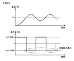
- FIG. 5 is a diagram illustrating an example of a temporal change in the temperature (observed amount) and the manipulated variable of the control target during execution of general auto tuning.
- FIG. 6 is a diagram illustrating an example of a temporal change in the temperature (observed amount) and the manipulated variable of the control target when feedback control is performed using the PID parameter determined by performing the auto-tuning illustrated in FIG. More specifically, FIG. 6A shows the relationship between the operation amount on the cooling side and the cooling capacity, and FIG. 6B shows the temperature (observed amount) to be controlled and the operation during feedback control. An example of the time change of quantity is shown.
- Fig. 5 shows an example of the auto-tuning function using the limit cycle method.
- the operation amount on the heating side and the operation amount on the cooling side are both set to maximum values (that is, 100% and ⁇ 100%), and these are alternately performed. Is given to the control target. Based on the response characteristics generated in this way, the PID parameter corresponding to the control target is determined.
- the actual characteristics are estimated when feedback control is performed in a region where the operation amount is relatively small.
- the actual characteristics will be greatly different from the actual characteristics. Therefore, when the control object 230 is controlled using a relatively small operation amount, the actual cooling capacity becomes higher than the assumption assumed by the PID parameter set by the auto-tuning function, and the control object 230 is cooled too much. Occurs.
- the cooling side operation amount is cooled in response to some disturbance as shown in FIG.
- the temperature drops excessively with respect to the target value, and vibrational temperature fluctuations occur, and it takes time to converge.
- the control performance deteriorates due to the difference between the cooling capacity estimated by the auto-tuning function and the actual cooling capacity.
- the most preferable amount of operation is searched while changing the operation amount used in auto-tuning step by step. Then, the PID parameter is determined based on the response characteristic at the most preferable operation amount.
- the regulator 100 performs output switching in the alternate output of the first operation amount (cooling side operation amount) and the second operation amount (heating side operation amount) as its auto-tuning function.
- the first operation amount (cooling side operation amount) is sequentially changed every time, and the first change of the control amount with respect to the first operation amount (cooling side operation amount) has linearity.
- PID parameters are determined from the response characteristics acquired when it is determined that That is, the regulator 100 executes the limit cycle a plurality of times while changing the operation amount on the cooling side stepwise.
- the regulator 100 calculates a PID parameter on the cooling side from the cooling characteristic (response characteristic) at that time. Note that the PID parameter on the heating side is also calculated from the heating characteristic (response characteristic).
- FIG. 7 is a diagram showing an example of a time waveform when auto-tuning is executed by the regulator 100 according to the present embodiment.
- FIG. 8 is a diagram showing a change in the characteristics of the cooling capacity of the operation amount at the time of execution of auto-tuning by the adjuster 100 according to the present embodiment.
- the regulator 100 since there is nonlinearity in the cooling capacity, the regulator 100 sequentially changes the magnitude of the operation amount on the cooling side in each cycle of auto-tuning as shown in FIG. . If the control system has non-linearity in the heating capacity, the magnitude of the operation amount on the heating side may be changed sequentially.
- the operation amount MVc_1 on the cooling side in the first limit cycle is set to 100%
- the operation amount MVc_2 on the cooling side in the second limit cycle is set to a value obtained by multiplying the first operation amount MVc_1 by ⁇ _1.
- the cooling operation amount MVc_3 in the third limit cycle is set to a value obtained by multiplying the second operation amount MVc_2 by ⁇ _2.
- the operation amount MVc on the cooling side is changed for each limit cycle.
- the size of the cooling capacity considered in the auto tuning changes sequentially as shown in FIG.
- the change coefficient ⁇ _i (0 ⁇ _i ⁇ 1) of the operation amount MVc on the cooling side a predetermined constant value may be adopted, but a new value is obtained from the response characteristic acquired by the immediately previous alternate output. It is preferable to determine the magnitude of the operation amount MVc on the cooling side in such alternate output.
- the following ratio representing the system gain ratio (capacity ratio) between heating and cooling is used.
- Change coefficient ⁇ _i cooling output time Toff_i ⁇ 1 / heating output time Ton_i ⁇ 1
- the cooling output time Toff_i-1 indicates the length of time during which the cooling-side manipulated variable MVc is maintained at 0 in the (i-1) th (previous) limit cycle
- the heating output time Ton_i-1 is (I-1) Indicates the length of time during which the cooling-side manipulated variable MVc is output in the first (previous) limit cycle (see FIG. 7).
- the change coefficient ⁇ _i may exceed 1 in the above equation, so the calculated change coefficient ⁇ _i is changed. It is preferable to limit so as to be equal to or less than the coefficient upper limit value ⁇ _max.
- the regulator 100 uses the length of the period (cooling output time Toff) during which the first operation amount (cooling side operation amount) is output in the immediately preceding alternate output and the second operation as its auto-tuning function.
- a new alternate output is obtained by correcting the magnitude of the first manipulated variable in the immediately preceding alternate output according to the length of the period (the heating output time Ton) in which the amount (the heating side manipulated variable) is output.
- the magnitude of the first manipulated variable at is determined.
- the operation amount is determined as follows.
- the control amount change speed corresponding to the first operation amount is changed according to the first operation amount (cooling side operation amount) that is sequentially changed.
- the linearity on the cooling characteristics can be evaluated using an error as described below. That is, the end condition of the limit cycle includes that the calculated error is equal to or less than a preset threshold value.
- the PID parameters are calculated using the limit sensitivity method of Ziegle and Nichols.
- a well-known arbitrary method is employable.
- the regulator 100 uses the auto-tuning function as the first tuning amount even if it is not determined that the first change in the controlled variable with respect to the first manipulated variable (cooling-side manipulated variable) has linearity.
- the PID parameter is determined from the response characteristics acquired in the final alternate output.
- an appropriate PID parameter can be calculated regardless of whether the controlled object has linearity or non-linearity.
- the type of coolant water or oil
- FIG. 9 is a diagram for explaining an error evaluation method in auto-tuning by the controller 100 according to the present embodiment.
- the “error” in the present embodiment is defined by the cooling capacity corresponding to the operation amount used in the previous limit cycle in the cooling characteristics (the relationship between the cooling capacity and the cooling operation amount). This corresponds to a value indicating the degree to which the cooling capacity corresponding to the operation amount used in the current limit cycle is separated from the straight line.
- the origin is defined as P0
- the cooling capacity point for the i-th limit cycle is defined as Pi (Pi.x, Pi.y).
- Pi. x represents the cooling side manipulated variable
- Pi. y represents the cooling capacity.
- a straight line Li connecting the cooling capacity Pi and the origin P0 is set.
- the error hi is calculated as the distance between the straight line L (i ⁇ 1) and the i-th cooling capacity Pi (Pi.x, Pi.y). That is, this distance is calculated as an error hi that is an index for linear determination at the i th limit cycle.
- FIG. 9 shows a calculation example of the error h2 for the second limit cycle.
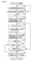
- FIG. 10 is a flowchart illustrating a processing procedure of auto-tuning executed in the regulator 100 according to the embodiment.
- Each step shown in FIG. 10 is typically realized by the CPU 112 of the controller 100 executing the instruction code included in the program module 118 stored in the Flash ROM 114.
- the processing procedure shown in FIG. 10 is repeatedly executed at a predetermined calculation cycle (for example, every 100 msec) when a user or the like instructs the start of auto-tuning.
- CPU 112 outputs 100% as the operation amount on the heating side (step S ⁇ b> 100), and the target value (setting) in which temperature (control target temperature) PV measured from control target process 200 is set. It is determined whether or not the temperature has reached SP (step S102). If the temperature PV to be controlled has not reached the set temperature SP (NO in step S102), the processing in step S100 and subsequent steps is repeated.
- step S104 If the temperature PV to be controlled has reached the set temperature SP (in the case of YES in step S102), the processes in and after step S104 are executed.
- the processing in steps S100 and S102 is preprocessing for generating a limit cycle related to auto tuning.
- the CPU 112 sets “1” to the counter i (step S104) and instructs the generation of the first limit cycle (step S106).
- This counter i indicates the number of limit cycles.
- the operation amount on the cooling side and the heating side in the first limit cycle is both 100%.
- the limit cycle generation instruction outputs the operation amount (100% in this case) on the cooling side until the temperature PV to be controlled matches the set temperature SP, and when the temperature PV to be controlled matches the set temperature SP, A series of processes of outputting the operation amount on the heating side (in this case, 100%) is included.
- the CPU 112 instructs the generation of the i-th limit cycle (step S112).
- the operation amount on the cooling side in the i-th limit cycle is MVc_i%, and the operation amount on the heating side is 100%.
- the limit cycle generation instruction outputs a cooling side operation amount (in this case, MVc_i%) until the temperature PV to be controlled matches the set temperature SP, and when the temperature PV to be controlled matches the set temperature SP, A series of processes of outputting the operation amount on the heating side (in this case, 100%) is included.
- the CPU 112 calculates an error hi from the current cooling characteristic (response characteristic) and the previous cooling characteristic (response characteristic) (step S114).
- the CPU 112 determines whether or not the calculated error hi is equal to or less than the threshold value ⁇ (step S116). If calculated error hi exceeds threshold value ⁇ (NO in step S116), CPU 112 determines whether or not the current value of counter i has reached maximum value N of the limit cycle. (Step S118).
- step S118 If the value of the current counter i has not reached the maximum value N of the limit cycle (NO in step S118), the CPU 112 executes processing in step S108 and subsequent steps.
- step S116 when the calculated error hi is equal to or less than the threshold value ⁇ (YES in step S116), or when the current counter i value has reached the maximum value N of the limit cycle (step S118).
- step S120 the CPU 112 calculates a PID parameter from the response characteristics in the i-th limit cycle (step S120). Then, the process ends.
- FIG. 11 is a schematic diagram showing a control configuration for realizing the auto-tuning function mounted on the regulator 100 according to the present embodiment.
- adjuster 100 has, as its control configuration, sensor output receiving unit 162, user setting receiving unit 164, heating side PID calculation unit 166, cooling side PID calculation unit 168, and switching unit 170.
- the sensor output receiving unit 162 receives an output signal from the temperature sensor 240, performs a predetermined range adjustment, and outputs the temperature PV to be controlled.
- the user setting receiving unit 164 receives the setting of the set temperature SP according to the user operation.
- the set temperature SP may be set from an external device (for example, PLC (Programmable Logic Control)).
- the heating-side PID calculation unit 166 and the cooling-side PID calculation unit 168 are parts for executing normal PID control, and the operation amount is determined from the temperature PV to be controlled and the set temperature SP according to the PID parameters 176 and 178, respectively.
- MVh and MVc are calculated and output, respectively.
- the PID parameters 176 and 178 may be directly input by the user, but in the present embodiment, they are automatically set by a PID parameter calculation unit 172 described later.
- the switching unit 170 switches and outputs the operation amounts MVh and MVc output from the heating side PID calculation unit 166 and the cooling side PID calculation unit 168, respectively, depending on the situation.
- the heating side PID calculation A configuration may be adopted in which only one of the unit 166 and the cooling side PID calculation unit 168 is selectively activated.
- the PID parameter calculation unit 172 and the auto tuning control unit 174 are parts for executing auto tuning.
- the auto-tuning control unit 174 generates operation amounts (operation amounts MVh and MVc) for generating the limit cycle as described above.
- the PID parameter calculation unit 172 determines the PID parameters 176 and 178 based on the heating characteristics and cooling characteristics (response characteristics) observed in the final limit cycle.
- Switch 180 switches the output source of the manipulated variable between normal control and auto tuning execution. That is, during normal control, the operation amount from the switching unit 170 is output to the control target process 200, and during auto tuning, the operation amount from the auto tuning control unit 174 is output to the control target process 200.
- FIG. 12 is an example showing a time waveform of each part related to auto-tuning according to the present embodiment.
- the non-linear point the portion where the characteristic changes rapidly
- the change coefficient upper limit value ⁇ _max was set to 0.4.
- the error hi is equal to or less than the threshold value ⁇ . Therefore, the PID parameter is determined based on the cooling characteristic and the heating characteristic (response characteristic) observed in the fifth limit cycle.
- the operation amount MVh on the heating side is maintained at 100%, while the operation amount MVc on the cooling side is gradually decreased.
- a PID parameter is determined using a limit sensitivity method or the like based on a limit cycle occurring at the temperature PV to be controlled.
- FIG. 13 is a diagram showing a comparative example of control performance using the PID parameter calculated by executing the auto-tuning shown in FIG.
- FIG. 12 shows the result of feedback control using PID parameters determined using conventional auto-tuning and the feedback control using PID parameters determined using auto-tuning according to the present embodiment. Results are shown.
- the temperature PV to be controlled can be matched with the set temperature SP with higher accuracy by using the PID parameter determined by the auto-tuning according to the present embodiment.
- the auto change is made when the third change is made among the cooling-side manipulated variables MVc shown in FIG. Tuning is complete. Even in this case, the operation amount MVc_3 on the cooling side in the third limit cycle and the operation amount MVc_5 on the cooling side in the fifth limit cycle are relatively close to each other. Therefore, an appropriate PID parameter is determined. it can. That is, the relationship between the time required for auto-tuning and the accuracy of the PID parameter is a kind of trade-off, but if auto-tuning is executed using an operation amount in a range used in normal PID control, nonlinearity is obtained. PID parameters that avoid the influence of sex can be determined.
- FIG. 14 is a schematic diagram illustrating an example of a user interface provided by the adjuster 100 according to the present embodiment.
- the adjuster 100 illustrated in FIG. 14 includes a display unit 150.
- the display unit 150 displays current values of the temperature PV to be controlled and the set temperature SP.
- the set temperature SP or the like is changed by the user operating a button or a switch arranged in the vicinity of the display unit 150.
- FIG. 14 shows a state during execution of auto tuning. As shown in FIG. 14, the number of limit cycles currently occurring, that is, how many limit cycles are being executed, is displayed as the value of the execution state of auto-tuning.
- Display unit 150 includes an indicator 152 that indicates the number of current limit cycles. That is, the controller 100 includes a display unit 150 as display means for displaying the number of alternating outputs currently being executed.
- the user can know how much auto-tuning will be completed by looking at the current number of limit cycles.
- the controller 100 may include a display unit 150 as a display unit that displays a time when the alternate output necessary for determining the PID parameter is completed.
- FIG. 15 is a schematic diagram illustrating another example of a user interface provided by the adjuster 100 according to the present embodiment.
- FIG. 15A shows an example of the display unit 150 including an indicator 154 that indicates the remaining time required for completion of auto-tuning.
- an indicator 154 that indicates the remaining time required for completion of auto-tuning.
- the remaining time can be calculated as the remaining time.
- the remaining time may be calculated from the time required to generate a half cycle (cooling side or heating side) of the limit cycle.
- the remaining time may be calculated based on the response characteristics acquired at that time.
- the display unit 150 illustrated in FIG. 15B includes an indicator 156 that indicates a time at which auto-tuning is predicted to be completed.
- the change coefficient ⁇ _i (or the change coefficient ⁇ (fixed value)) may be appropriately set according to the control target.
- the time required for auto tuning as much as possible. Therefore, as a modification of the change coefficient, a configuration for completing the auto-tuning in a shorter time without losing the technical significance of the system gain ratio (capacity ratio) between heating and cooling described above will be described. To do.
- Change coefficient ⁇ _i cooling output time Toff_i ⁇ 1 / heating output time Ton_i ⁇ 1
- Manipulation amount MVc_i MVc — 1 ⁇ 1 ⁇ ⁇ _i ⁇ ⁇ _i
- the first operation amount (the heating output time Ton) with respect to the length of the period (heating output time Ton) during which the second operation amount (heating-side output) in the immediately preceding alternate output is output By correcting the magnitude of the first manipulated variable in the immediately preceding alternate output according to the square of the ratio ( ⁇ ) of the length of the period (cooling output time Toff) during which the output on the heating side is output, The magnitude of the first manipulated variable in the new alternate output is determined.
- FIG. 16 is an example showing a time waveform of each part related to auto-tuning according to the first modification of the present embodiment.
- the manipulated variable MVc is sequentially changed by multiplying by the change coefficient ⁇ _i (FIG. 12)
- the error hi does not become the threshold value ⁇ or less unless five limit cycles are generated.
- the error hi can be made equal to or less than the threshold value ⁇ by generating the limit cycle three times.
- the time for auto-tuning can be shortened by increasing the degree of changing the operation amount MVc.
- the cooling capacity is larger than the heating capacity and has non-linearity.
- the accuracy can be increased as the limit cycle to be generated is made closer to a sine wave.
- FIG. 17 is a diagram illustrating an example of a relationship between the heating capacity and the cooling capacity and the operation amount (heating and cooling) in the process to be controlled illustrated in FIG.
- the first quadrant shows the relationship between the heating capacity (vertical axis) and the operation amount (heating) (horizontal axis).
- Ah indicates the magnitude of the heating capacity [° C./sec] when the operation amount (heating) is 100%.
- the third quadrant shows the relationship between the cooling capacity (vertical axis) and the operation amount (cooling) (horizontal axis).
- Ac indicates the size of the cooling capacity [° C./sec] when the operation amount (cooling) is 100%. Since the cooling capacity varies depending on the installation conditions and setting conditions of the equipment, FIG. 17 shows the characteristics of the cooling capacity when the setting conditions are changed to three.
- a point at which the characteristic of the cooling capacity changes (a point indicated by a mark ⁇ in FIG. 17) is defined as a non-linear point.
- MVc_2 100% ⁇ change coefficient ⁇ _2
- the operation amount MVc_2 on the cooling side in the second limit cycle calculated according to this mathematical formula is indicated by a circle.
- the above formula corresponds to a calculation formula for balancing the heating capability and the cooling capability when the characteristics of the cooling capability are linear.
- the range of the cooling characteristic (linear characteristic) to be calculated for the cooling characteristic 1 is an area where the operation amount is smaller than the point indicated by a circle. Therefore, simply by multiplying the ratio of heating and cooling (capacity ratio), the operation amount MVc_2 on the cooling side in the second limit cycle is larger than the non-linear point (position indicated by the mark ⁇ ), and is indicated by the arrow in FIG. The characteristics of the range (linear part) cannot be captured. Also, with respect to the other cooling characteristics shown in FIG. 17, since the respective nonlinear points (positions indicated by ⁇ ) change, the linear portion is captured only by multiplying the system gain ratio (capacity ratio) between heating and cooling. I can't.
- the non-linear point As shown in cooling capacities 1 to 3 in FIG. 17, the non-linear point (position indicated by the mark ⁇ ) tends to approach the Y-axis as the cooling capacity (Ac shown in FIG. 17) increases. That is, it can be said that the X-coordinate value of the non-linear point (position indicated by the mark ⁇ ) has a causal relationship with the reciprocal of the cooling capacity (1 / Ac).
- the characteristics as shown in FIG. 17 are obtained in the extruder 232 including the heating device 210 and the cooling device 220.
- the control amount for the heating generated in the control target by the heating device 210 has a relatively strong linearity with respect to the corresponding operation amount
- the control amount for the cooling generated in the control target by the cooling device 220 corresponds to the control amount. It has a relatively strong non-linearity with respect to the manipulated variable.
- the operating amount on the cooling side in the calculated second limit cycle (dotted circle) is closer to the vertical axis than the non-linear point (position indicated by ⁇ ), and the characteristics of the linear part are Can be caught. This relationship is considered to hold in the extruder 232 even if the cooling capacity changes.
- the above equation including the correction coefficient Xc can be modified as follows.
- the operation amount MVc_i is sequentially changed by using a value obtained by multiplying the current operation amount by the nth power of the change coefficient ⁇ _i. It is preferable to use a value in the vicinity of 2 as n to the power of n. More specifically, the controller 100 uses n that satisfies 1.5 ⁇ n ⁇ 3.0 to adjust the magnitude of the first operation amount (cooling side operation amount) in the new alternate output. decide.
- the manipulated variable MVc in a new limit cycle is calculated by multiplying the manipulated variable MVc by the nth power of the change coefficient.
- the time for auto tuning can be shortened.
- FIG. 18 is a diagram for explaining a process of determining parameters according to the third modification of the present embodiment.
- the limit cycle (first time) is generated with the operation amount MVc on the cooling side set to 100%.
- the operation amount MVh on the heating side is also set to 100%.
- the cooling capacity Yc [° C./sec] is calculated from the response characteristic (time waveform) acquired by the occurrence of the limit cycle. Even if the cooling-side manipulated variable MVc is changed, assuming that the cooling capacity Yc does not change, if the second limit cycle is generated, the characteristics that will be obtained are estimated.
- the operation amount Xc on the cooling side corresponding to the non-linear point (the point indicated by ⁇ in FIG. 18) is calculated by the method according to the above-described modification 2. That is, based on the response characteristics generated in the first limit cycle, the change coefficient ⁇ is determined from the ratio of the cooling output time Toff to the heating output time Ton, and the determined change coefficient ⁇ is n-th power (where 1. 5 ⁇ n ⁇ 3.0) is determined as the cooling-side manipulated variable Xc corresponding to the nonlinear point. Furthermore, a value obtained by multiplying a correction coefficient determined statically or dynamically may be adopted.
- the manipulated variable Xc [%] determined by the procedure as described above. ] Is used to estimate the characteristic value of the nonlinear point. That is, the coordinates of the nonlinear point in the coordinate system shown in FIG. 18 are [Xc, Yc].
- the slope Ac [° C./sec] for the straight line (estimated line) connecting the nonlinear point [Xc, Yc] and the origin [0, 0] is determined as the cooling capacity in the range of the manipulated variable Xc in which the linearity is maintained. .
- the PID parameter is determined.
- the cooling capacity Yc [° C./sec] is calculated from the first limit cycle response characteristic (time waveform), and (2) the cooling operation amount Xc [%] at the non-linear point.
- the non-linear point [Xc, Yc] is determined on the assumption that the cooling capacity is maintained at the same level as when the operation amount on the cooling side is 100%, and (4) the non-linear point [Xc, Yc] ] And the slope Ac of the estimated line passing through the origin is calculated as the cooling capacity, and (5) the PID parameter is calculated using the cooling capacity Ac.
- the controller 100 has an auto-tuning function in which the first operation amount (cooling side operation amount) and the second operation amount (heating side operation amount) are alternately set to 1 according to the observation amount. PID parameters from response characteristics (time waveform) obtained by alternating output of the first operation amount (cooling side operation amount) and the second operation amount (heating side operation amount) one by one. To decide.
- the controller 100 uses the first operation amount (cooling-side operation) that can maintain linearity from the response characteristic in the first change of the control amount with respect to the first operation amount (cooling-side operation amount). Amount) (ie, a non-linear point) and a PID parameter is determined from the estimated range.
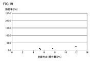
- FIG. 19 is a diagram illustrating an evaluation result example of the error rate of the PID parameter calculated by the auto-tuning function according to the present modification.
- the error rate e calculated for each estimated nonlinear point (cooling side operation amount) is plotted.
- This error rate e is as follows using the proportional band Pb0 calculated using the auto-tuning function according to the present embodiment and the proportional band Pb calculated using the auto-tuning function according to the present modification. It is calculated according to the formula shown.
- FIG. 19 shows an evaluation result when applied to a cast-in heater cooling system as shown in the cooling device 220 shown in FIG. According to the evaluation results shown in FIG. 19, the error rate has an average of about 10% and a maximum value as compared with the auto-tuning function (actual measurement of nonlinear point characteristics) according to the above-described embodiment. But it is within 25%. Therefore, it can be seen that sufficiently practical accuracy can be obtained.
- the second limit cycle is not generated, the nonlinear point is estimated from the response characteristic (time waveform) acquired by the first limit cycle, and the PID parameter is determined.
- 1 feedback control system 100 regulator, 110 control unit, 112 CPU, 114 ROM, 116 RAM, 118 program module, 120 input unit, 130 output unit, 132 heating side output unit, 134 cooling side output unit, 140 setting unit, 150, display unit, 152, 154, 156 indicator, 162 sensor output reception unit, 164 user setting reception unit, 166 heating side PID calculation unit, 168 cooling side PID calculation unit, 170 switching unit, 172 PID parameter calculation unit, 174 auto tuning Control unit, 176 PID parameter, 180 switch, 200 process to be controlled, 210 heating device, 212 solid state relay, 214 electric heater, 220 cooling device, 222 cooling pipe, 224 solenoid valve, 26 the water temperature adjustment equipment, 230 control target, 232 extruder, 234 screw, 236 barrels, 240 temperature sensor.
Landscapes
- Engineering & Computer Science (AREA)
- Physics & Mathematics (AREA)
- General Physics & Mathematics (AREA)
- Automation & Control Theory (AREA)
- Health & Medical Sciences (AREA)
- Artificial Intelligence (AREA)
- Computer Vision & Pattern Recognition (AREA)
- Evolutionary Computation (AREA)
- Medical Informatics (AREA)
- Software Systems (AREA)
- Feedback Control In General (AREA)
- Control Of Temperature (AREA)
Abstract
Description
まず、本実施の形態に係る調節器の制御対象について説明する。図1は、本実施の形態に係るフィードバック制御系1を示す模式図である。図1を参照して、フィードバック制御系1は、調節器100と、制御対象プロセス200とを含む。制御対象プロセス200は、アクチュエータとして加熱装置210および冷却装置220を含み、これらの装置が制御対象230に対して加熱または冷却を行う。
次に、図1に示すフィードバック制御系1を押出成形機のプロセスに適用した実装例について説明する。図2は、本実施の形態に係るフィードバック制御系1を実現するシステム構成を示す模式図である。
次に、図2に示すフィードバック制御系1において生じ得る、操作量と制御対象に生じる制御量との間の非線形性に由来する制御上の課題について説明する。特に、オートチューニングを実行した場合に生じる課題について説明する。
冷却能力[%]=任意操作量での冷却温度[℃/sec]/最大冷却温度[℃/sec]×100[%]
まず、加熱特性(加熱の操作量に対する加熱能力の関係)については、図3に示すように、ほぼリニアである。つまり線形性を有しているといえる。これは、加熱装置210として電熱ヒータ214が用いられており、操作量に比例する電流(電力)を供給することで、発熱量をリニアに制御できるからである。
上述のような強い非線形性を有する制御対象230を含むフィードバック制御系に対して、より適切なPIDパラメータを設定できるオートチューニング機能について説明する。
但し、冷却出力時間Toff_i-1は、(i-1)回目(前回)のリミットサイクルにおいて冷却側の操作量MVcが0に維持される時間の長さを示し、加熱出力時間Ton_i-1は、(i-1)回目(前回)のリミットサイクルにおいて冷却側の操作量MVcが出力される時間の長さを示す(図7参照)。
次に、線形性を有している領域の操作量であるか否かを判断するための誤差について説明する。図9は、本実施の形態に係る調節器100によるオートチューニングにおける誤差の評価方法を説明するための図である。図9に示すように、本実施の形態における「誤差」は、冷却特性(冷却の操作量に対する冷却能力の関係)において、前回のリミットサイクルで用いた操作量に対応する冷却能力で定義される直線に対して、今回のリミットサイクルで用いた操作量に対応する冷却能力がどの程度離れているかという度合いを示す値に相当する。
次に、本実施の形態に係る調節器100において実行されるオートチューニングの処理手順について説明する。図10は、実施の形態に係る調節器100において実行されるオートチューニングの処理手順を示すフローチャートである。図10に示す各ステップは、典型的には、調節器100のCPU112がFlashROM114に格納されたプログラムモジュール118に含まれる命令コードを実行することで実現される。図10に示す処理手順は、ユーザなどがオートチューニングの開始を指示すると、予め定められた演算周期(例えば、100msec毎)に繰返し実行される。
次に、本実施の形態に係る調節器100に搭載されるオートチューニング機能を実現する制御構成について説明する。図11は、本実施の形態に係る調節器100に搭載されるオートチューニング機能を実現する制御構成を示す模式図である。
次に、本実施の形態に係るオートチューニング機能の効果をシミュレーションによって評価した結果について説明する。
オートチューニングでは、制御対象に対して実際に何らかの操作量を与えて、その応答特性に基づいてPIDパラメータを算出する。特に、リミットサイクル法では、観測量(PV)を振動させて制御系の特性値を推定するため、時定数の長い制御系では、必要な応答特性を観測するために比較的長い時間を要する。そのため、オートチューニングの実行中において、その実行状態や完了時期(予測値)などをユーザへ通知することが、よりユーザフレンドリである。
まず、オートチューニングの実行状態を通知するユーザインターフェイスについて説明する。図14は、本実施の形態に係る調節器100が提供するユーザインターフェイスの一例を示す模式図である。図14に示す調節器100は、表示部150を有している。表示部150には、制御対象の温度PVおよび設定温度SPの現在値が表示されている。また、表示部150に近接して配置されたたボタンやスイッチなどをユーザが操作することで、設定温度SPなどが変更される。
図14に示す現在のリミットサイクルの回数に代えて、あるいは、それ加えて、オートチューニングの完了までに要する時間を通知するようにしてもよい。すなわち、調節器100は、PIDパラメータの決定に必要な交互出力が完了する時期を表示する表示手段としての表示部150を含むようにしてもよい。
上述の実施の形態においては、加熱と冷却とのシステムゲイン比(能力比)を表す変更係数ρ_iを乗じることで、冷却側の操作量MVcを順次変更する構成例について説明した。この変更係数ρ_iについては、これに限らず任意の値に設定できる。また、各リミットサイクルにおいて変更係数ρ_iを動的に決定する構成に代えて、一連のオートチューニングにおいて変更係数ρとして固定値を採用してもよい。
操作量MVc_i=MVc_1-1×ρ_i×ρ_i
このように、変更係数ρ_iの二乗を用いることで、図12に示すような冷却側の操作量MVcを段階的に変更する処理において、実質的に一つ飛ばしで操作量MVcを変更することになる。すなわち、調節器100は、そのオートチューニング機能として、直前の交互出力における第2の操作量(加熱側の出力)が出力された期間(加熱出力時間Ton)の長さに対する第1の操作量(加熱側の出力)が出力された期間(冷却出力時間Toff)の長さの比(ρ)の二乗に応じて、当該直前の交互出力における第1の操作量の大きさを補正することで、新たな交互出力における第1の操作量の大きさを決定する。
上述の変形例1においては、加熱と冷却とのシステムゲイン比(能力比)を表す変更係数ρ_iの二乗を乗じることで、操作量MVcを順次変更する例について説明した。しかしながら、変更係数ρ_iの二乗に限られることなく、変更係数ρ_iのn乗(n>1)を乗じて、操作量MVcを順次変更してもよい。以下、このような変更係数ρ_iのn乗(n>1)を乗じて、操作量MVcを順次変更してもよい理由について説明する。
図17において、この数式に従って算出される2回目のリミットサイクルにおける冷却側の操作量MVc_2を○印で示す。すなわち、上の数式は、冷却能力の特性を線形とした場合に、加熱の能力と冷却の能力とのバランスを揃えるための計算式に相当する。
このような数式を用いることで、図17において、○印で示す位置(変更係数ρ_1を乗じることで算出される2回目のリミットサイクルにおける冷却側の操作量)は、さらにXc倍され、非線形点(●印で示す位置)より小さい点(つまり、ゼロ側)へ補正されることになる(破線の丸印)。
MVc_2=100%×変更係数ρ_2×変更係数ρ_2m
=100%×変更係数ρ_2(m+1)=100%×変更係数ρ_2n
このように、現在の操作量に変更係数ρ_iのn乗を乗じた値を用いることで、操作量MVc_iが順次変更される。このn乗のnとしては、2の近傍の値を用いることが好ましい。より具体的には、調節器100は、1.5≦n≦3.0を満たすようなnを用いて、新たな交互出力における第1の操作量(冷却側の操作量)の大きさを決定する。
上述の実施の形態においては、リミットサイクルを複数回発生させる例について説明したが、ある種類の制御対象については、1回のリミットサイクルによって取得される応答特性のみから適切なパラメータを決定することもできる。以下、1回のリミットサイクルを発生、つまり第1の操作量(冷却側の操作量)および第2の操作量(加熱側の操作量)を観測量に応じて交互に出力し、それによって取得される応答特性のみからパラメータを決定する方法について説明する。
図19には、図2に示す冷却装置220に示すような、鋳込みヒータ冷却方式に適用した場合の評価結果を示す。図19に示す評価結果によれば、上述の本実施の形態に係るオートチューニング機能(非線形点の特性を実際に計測)に比較して、その誤差率は、平均が約10%で、最大値でも25%以内に収まっている。そのため、十分に実用的な精度が得られることがわかる。
Claims (21)
- オートチューニング機能を有する調節器であって、
制御対象から取得される観測量が目標値と一致するように、予め設定されたパラメータに従って、前記制御対象の制御量に第1の変化を生じさせるための第1の操作量、または、前記制御量に前記第1の変化とは反対の第2の変化を生じさせるための第2の操作量、を選択的に決定する操作量決定手段と、
前記第1の操作量および前記第2の操作量を前記観測量に応じて交互に出力し、当該交互出力によって取得された応答特性から前記パラメータを決定するチューニング手段とを備え、
前記チューニング手段は、前記第1の操作量および前記第2の操作量の交互出力において、出力の切替毎に前記第1の操作量の大きさを順次変更するとともに、前記第1の操作量に対する前記制御量の第1の変化が線形性を有していると判断されたときに取得された応答特性から前記パラメータを決定する、調節器。 - 前記チューニング手段は、直前の交互出力によって取得された応答特性から、新たな交互出力における前記第1の操作量の大きさを決定する、請求項1に記載の調節器。
- 前記チューニング手段は、直前の交互出力において前記第1の操作量が出力された期間の長さと前記第2の操作量が出力された期間の長さとに応じて、当該直前の交互出力における前記第1の操作量の大きさを補正することで、新たな交互出力における前記第1の操作量の大きさを決定する、請求項2に記載の調節器。
- 前記チューニング手段は、順次変更される前記第1の操作量の大きさの別に、前記第1の操作量に対応する前記制御量の変化速度との関係を評価することで、前記第1の操作量に対する前記制御量の第1の変化が線形性を有しているか否かを判断する、請求項1~3のいずれか1項に記載の調節器。
- 前記チューニング手段は、前記第1の操作量に対する前記制御量の第1の変化が線形性を有していると判断されなくとも、前記第1の操作量および前記第2の操作量の交互出力が予め定められた回数実行されると、最終の交互出力において取得された応答特性から前記パラメータを決定する、請求項1~4のいずれか1項に記載の調節器。
- オートチューニング機能を有する調節器であって、
制御対象から取得される観測量が目標値と一致するように、予め設定されたパラメータに従って、前記制御対象の制御量に第1の変化を生じさせるための第1の操作量、または、前記制御量に前記第1の変化とは反対の第2の変化を生じさせるための第2の操作量、を選択的に決定する操作量決定手段と、
前記第1の操作量および前記第2の操作量を前記観測量に応じて交互に出力し、当該交互出力によって取得された応答特性から前記パラメータを決定するチューニング手段とを備え、
前記チューニング手段は、直前の交互出力における前記第2の操作量が出力された期間の長さに対する前記第1の操作量が出力された期間の長さの比のn乗(n>1)に応じて、当該直前の交互出力における前記第1の操作量の大きさを補正することで、新たな交互出力における前記第1の操作量の大きさを決定する、調節器。 - 前記チューニング手段は、1.5≦n≦3.0を満たすようなnを用いて、新たな交互出力における前記第1の操作量の大きさを決定する、請求項6に記載の調節器。
- 前記制御対象は、加熱装置および冷却装置を含む押出成形機を含み、前記加熱装置により前記制御対象に生じる加熱についての制御量は、対応する操作量について相対的に強い線形性を有しており、前記冷却装置により前記制御対象に生じる冷却についての制御量は、対応する操作量について相対的に強い非線形性を有している、請求項6または7に記載の調節器。
- オートチューニング機能を有する調節器であって、
制御対象から取得される観測量が目標値と一致するように、予め設定されたパラメータに従って、前記制御対象の制御量に第1の変化を生じさせるための第1の操作量、または、前記制御量に前記第1の変化とは反対の第2の変化を生じさせるための第2の操作量、を選択的に決定する操作量決定手段と、
前記第1の操作量および前記第2の操作量を前記観測量に応じて交互に1回ずつ出力し、前記第1の操作量および前記第2の操作量の1回ずつの交互出力によって取得された応答特性から前記パラメータを決定するチューニング手段とを備え、
前記チューニング手段は、前記応答特性から前記第1の操作量に対する前記制御量の第1の変化が線形性を維持できる前記第1の操作量の範囲を推定するとともに、当該推定した範囲から前記パラメータを決定する、調節器。 - オートチューニング機能を有する調節器であって、
制御対象から取得される観測量が目標値と一致するように、予め設定されたパラメータに従って、前記制御対象の制御量に第1の変化を生じさせるための第1の操作量、または、前記制御量に前記第1の変化とは反対の第2の変化を生じさせるための第2の操作量、を選択的に決定する操作量決定手段と、
前記第1の操作量および前記第2の操作量を前記観測量に応じて交互に出力し、当該交互出力によって取得された応答特性から前記パラメータを決定するチューニング手段と、
現在実行されている交互出力の回数を表示する表示手段とを備える、調節器。 - オートチューニング機能を有する調節器であって、
制御対象から取得される観測量が目標値と一致するように、予め設定されたパラメータに従って、前記制御対象の制御量に第1の変化を生じさせるための第1の操作量、または、前記制御量に前記第1の変化とは反対の第2の変化を生じさせるための第2の操作量、を選択的に決定する操作量決定手段と、
前記第1の操作量および前記第2の操作量を前記観測量に応じて交互に出力し、当該交互出力によって取得された応答特性から前記パラメータを決定するチューニング手段と、
前記パラメータの決定に必要な交互出力が完了する時期を表示する表示手段とを備える、調節器。 - オートチューニング機能を有する調節器における制御方法であって、
制御対象から取得される観測量が目標値と一致するように、予め設定されたパラメータに従って、前記制御対象の制御量に第1の変化を生じさせるための第1の操作量、または、前記制御量に前記第1の変化とは反対の第2の変化を生じさせるための第2の操作量、を選択的に決定するステップと、
前記第1の操作量および前記第2の操作量を前記観測量に応じて交互に出力し、当該交互出力によって取得された応答特性から前記パラメータを決定するステップとを備え、
前記パラメータを決定するステップは、前記第1の操作量および前記第2の操作量の交互出力において、出力の切替毎に前記第1の操作量の大きさを順次変更するとともに、前記第1の操作量に対する前記制御量の第1の変化が線形性を有していると判断されたときに取得された応答特性から前記パラメータを決定するステップを含む、制御方法。 - オートチューニング機能を有する調節器における制御方法であって、
制御対象から取得される観測量が目標値と一致するように、予め設定されたパラメータに従って、前記制御対象の制御量に第1の変化を生じさせるための第1の操作量、または、前記制御量に前記第1の変化とは反対の第2の変化を生じさせるための第2の操作量、を選択的に決定するステップと、
前記第1の操作量および前記第2の操作量を前記観測量に応じて交互に出力し、当該交互出力によって取得された応答特性から前記パラメータを決定するステップとを備え、
前記パラメータを決定するステップは、直前の交互出力における前記第2の操作量が出力された期間の長さに対する前記第1の操作量が出力された期間の長さの比のn乗(n>1)に応じて、当該直前の交互出力における前記第1の操作量の大きさを補正することで、新たな交互出力における前記第1の操作量の大きさを決定するステップを含む、制御方法。 - オートチューニング機能を有する調節器における制御方法であって、
制御対象から取得される観測量が目標値と一致するように、予め設定されたパラメータに従って、前記制御対象の制御量に第1の変化を生じさせるための第1の操作量、または、前記制御量に前記第1の変化とは反対の第2の変化を生じさせるための第2の操作量、を選択的に決定するステップと、
前記第1の操作量および前記第2の操作量を前記観測量に応じて交互に1回ずつ出力し、前記第1の操作量および前記第2の操作量の1回ずつの交互出力によって取得された応答特性から前記パラメータを決定するステップとを備え、
前記パラメータを決定するステップは、前記応答特性から前記第1の操作量に対する前記制御量の第1の変化が線形性を維持できる前記第1の操作量の範囲を推定するとともに、当該推定した範囲から前記パラメータを決定するステップを含む、制御方法。 - オートチューニング機能を有する調節器における制御方法であって、
制御対象から取得される観測量が目標値と一致するように、予め設定されたパラメータに従って、前記制御対象の制御量に第1の変化を生じさせるための第1の操作量、または、前記制御量に前記第1の変化とは反対の第2の変化を生じさせるための第2の操作量、を選択的に決定するステップと、
前記第1の操作量および前記第2の操作量を前記観測量に応じて交互に出力し、当該交互出力によって取得された応答特性から前記パラメータを決定するステップと、
現在実行されている交互出力の回数を表示するステップとを備える、制御方法。 - オートチューニング機能を有する調節器における制御方法であって、
制御対象から取得される観測量が目標値と一致するように、予め設定されたパラメータに従って、前記制御対象の制御量に第1の変化を生じさせるための第1の操作量、または、前記制御量に前記第1の変化とは反対の第2の変化を生じさせるための第2の操作量、を選択的に決定するステップと、
前記第1の操作量および前記第2の操作量を前記観測量に応じて交互に出力し、当該交互出力によって取得された応答特性から前記パラメータを決定するステップと、
前記パラメータの決定に必要な交互出力が完了する時期を表示するステップとを備える、制御方法。 - オートチューニング機能を有する調節器を実現する制御プログラムであって、プロセッサに
制御対象から取得される観測量が目標値と一致するように、予め設定されたパラメータに従って、前記制御対象の制御量に第1の変化を生じさせるための第1の操作量、または、前記制御量に前記第1の変化とは反対の第2の変化を生じさせるための第2の操作量、を選択的に決定するステップと、
前記第1の操作量および前記第2の操作量を前記観測量に応じて交互に出力し、当該交互出力によって取得された応答特性から前記パラメータを決定するステップとを実行させ、
前記パラメータを決定するステップは、前記第1の操作量および前記第2の操作量の交互出力において、出力の切替毎に前記第1の操作量の大きさを順次変更するとともに、前記第1の操作量に対する前記制御量の第1の変化が線形性を有していると判断されたときに取得された応答特性から前記パラメータを決定するステップを含む、制御プログラム。 - オートチューニング機能を有する調節器を実現する制御プログラムであって、プロセッサに
制御対象から取得される観測量が目標値と一致するように、予め設定されたパラメータに従って、前記制御対象の制御量に第1の変化を生じさせるための第1の操作量、または、前記制御量に前記第1の変化とは反対の第2の変化を生じさせるための第2の操作量、を選択的に決定するステップと、
前記第1の操作量および前記第2の操作量を前記観測量に応じて交互に出力し、当該交互出力によって取得された応答特性から前記パラメータを決定するステップとを実行させ、
前記パラメータを決定するステップは、直前の交互出力における前記第2の操作量が出力された期間の長さに対する前記第1の操作量が出力された期間の長さの比のn乗(n>1)に応じて、当該直前の交互出力における前記第1の操作量の大きさを補正することで、新たな交互出力における前記第1の操作量の大きさを決定するステップを含む、制御プログラム。 - オートチューニング機能を有する調節器を実現する制御プログラムであって、プロセッサに
制御対象から取得される観測量が目標値と一致するように、予め設定されたパラメータに従って、前記制御対象の制御量に第1の変化を生じさせるための第1の操作量、または、前記制御量に前記第1の変化とは反対の第2の変化を生じさせるための第2の操作量、を選択的に決定するステップと、
前記第1の操作量および前記第2の操作量を前記観測量に応じて交互に1回ずつ出力し、前記第1の操作量および前記第2の操作量の1回ずつの交互出力によって取得された応答特性から前記パラメータを決定するステップとを実行させ、
前記パラメータを決定するステップは、前記応答特性から前記第1の操作量に対する前記制御量の第1の変化が線形性を維持できる前記第1の操作量の範囲を推定するとともに、当該推定した範囲から前記パラメータを決定するステップを含む、制御プログラム。 - オートチューニング機能を有する調節器を実現する制御プログラムであって、プロセッサに
制御対象から取得される観測量が目標値と一致するように、予め設定されたパラメータに従って、前記制御対象の制御量に第1の変化を生じさせるための第1の操作量、または、前記制御量に前記第1の変化とは反対の第2の変化を生じさせるための第2の操作量、を選択的に決定するステップと、
前記第1の操作量および前記第2の操作量を前記観測量に応じて交互に出力し、当該交互出力によって取得された応答特性から前記パラメータを決定するステップと、
現在実行されている交互出力の回数を表示するステップとを実行させる、制御プログラム。 - オートチューニング機能を有する調節器を実現する制御プログラムであって、プロセッサに
制御対象から取得される観測量が目標値と一致するように、予め設定されたパラメータに従って、前記制御対象の制御量に第1の変化を生じさせるための第1の操作量、または、前記制御量に前記第1の変化とは反対の第2の変化を生じさせるための第2の操作量、を選択的に決定するステップと、
前記第1の操作量および前記第2の操作量を前記観測量に応じて交互に出力し、当該交互出力によって取得された応答特性から前記パラメータを決定するステップと、
前記パラメータの決定に必要な交互出力が完了する時期を表示するステップとを実行させる、制御プログラム。
Priority Applications (7)
| Application Number | Priority Date | Filing Date | Title |
|---|---|---|---|
| KR1020157013777A KR101738282B1 (ko) | 2012-12-07 | 2013-11-11 | 조절기, 제어 방법 및 제어 프로그램 |
| CN201380061335.8A CN104813244B (zh) | 2012-12-07 | 2013-11-11 | 调节器以及控制方法 |
| KR1020177012724A KR101849509B1 (ko) | 2012-12-07 | 2013-11-11 | 조절기, 제어 방법 및 제어 프로그램이 기록된 기록 매체 |
| EP13860031.7A EP2930573B1 (en) | 2012-12-07 | 2013-11-11 | Adjustment device, control method, and control program |
| US14/646,993 US10248084B2 (en) | 2012-12-07 | 2013-11-11 | Controller, control method, and control program |
| JP2014551009A JP5983765B2 (ja) | 2012-12-07 | 2013-11-11 | 調節器、制御方法および制御プログラム |
| TW102144573A TWI587106B (zh) | 2012-12-07 | 2013-12-05 | 調節器、控制方法及記錄有控制程式的記錄媒體 |
Applications Claiming Priority (2)
| Application Number | Priority Date | Filing Date | Title |
|---|---|---|---|
| JP2012268201 | 2012-12-07 | ||
| JP2012-268201 | 2012-12-07 |
Publications (1)
| Publication Number | Publication Date |
|---|---|
| WO2014087805A1 true WO2014087805A1 (ja) | 2014-06-12 |
Family
ID=50883231
Family Applications (1)
| Application Number | Title | Priority Date | Filing Date |
|---|---|---|---|
| PCT/JP2013/080404 Ceased WO2014087805A1 (ja) | 2012-12-07 | 2013-11-11 | 調節器、制御方法および制御プログラム |
Country Status (7)
| Country | Link |
|---|---|
| US (1) | US10248084B2 (ja) |
| EP (1) | EP2930573B1 (ja) |
| JP (2) | JP5983765B2 (ja) |
| KR (2) | KR101849509B1 (ja) |
| CN (1) | CN104813244B (ja) |
| TW (1) | TWI587106B (ja) |
| WO (1) | WO2014087805A1 (ja) |
Cited By (2)
| Publication number | Priority date | Publication date | Assignee | Title |
|---|---|---|---|---|
| JP2015124835A (ja) * | 2013-12-26 | 2015-07-06 | 東ソー株式会社 | 電磁弁駆動回路 |
| WO2017077565A1 (ja) * | 2015-11-02 | 2017-05-11 | 理化工業株式会社 | Pid制御装置及びpid制御方法 |
Families Citing this family (10)
| Publication number | Priority date | Publication date | Assignee | Title |
|---|---|---|---|---|
| US10496057B2 (en) * | 2015-01-19 | 2019-12-03 | Lennox Industries Inc. | HVAC system, a method for operating the HVAC system and a HVAC controller configured for the same |
| JP6383309B2 (ja) * | 2015-03-17 | 2018-08-29 | アズビル株式会社 | 制御装置および制御方法 |
| TWI564683B (zh) * | 2015-10-21 | 2017-01-01 | 財團法人工業技術研究院 | 未知pid控制器之參數調諧方法 |
| WO2017077309A1 (en) * | 2015-11-06 | 2017-05-11 | Bae Systems Plc | Aircraft environmental control system |
| WO2018100670A1 (ja) * | 2016-11-30 | 2018-06-07 | 理化工業株式会社 | オートチューニング装置 |
| JP7164348B2 (ja) | 2018-07-27 | 2022-11-01 | アズビル株式会社 | 調節計 |
| US11169204B2 (en) * | 2018-11-29 | 2021-11-09 | Tokyo Electron Limited | Temperature control device, temperature control method, and inspection apparatus |
| JP7304722B2 (ja) * | 2018-11-29 | 2023-07-07 | 東京エレクトロン株式会社 | 温度制御装置、温度制御方法、および検査装置 |
| JP2020160659A (ja) * | 2019-03-26 | 2020-10-01 | アズビル株式会社 | 制御装置および制御方法 |
| JP7361624B2 (ja) * | 2020-02-12 | 2023-10-16 | 東京エレクトロン株式会社 | 加熱源の寿命推定システム、寿命推定方法、および検査装置 |
Citations (7)
| Publication number | Priority date | Publication date | Assignee | Title |
|---|---|---|---|---|
| JPH0527802A (ja) * | 1991-07-17 | 1993-02-05 | Rika Kogyo Kk | 調節計 |
| JPH05289704A (ja) | 1992-04-11 | 1993-11-05 | Rika Kogyo Kk | 加熱冷却調節計 |
| JPH06161569A (ja) * | 1992-11-19 | 1994-06-07 | Komatsu Ltd | 冷熱可能素子の温度制御方法 |
| JPH06161509A (ja) * | 1992-11-24 | 1994-06-07 | Mitsubishi Electric Corp | オートチューニングコントローラ |
| JP3211444B2 (ja) * | 1993-01-11 | 2001-09-25 | オムロン株式会社 | 制御装置 |
| JP2004227062A (ja) | 2003-01-20 | 2004-08-12 | Yamatake Corp | リミットサイクルオートチューニング方法およびヒートクール制御装置 |
| JP2009157691A (ja) * | 2007-12-27 | 2009-07-16 | Omron Corp | オートチューニング方法、温度調節器および熱処理装置 |
Family Cites Families (11)
| Publication number | Priority date | Publication date | Assignee | Title |
|---|---|---|---|---|
| US4912381A (en) * | 1985-05-31 | 1990-03-27 | Kollmorgen Corporation | Adaptive control system |
| CN1026444C (zh) | 1987-04-03 | 1994-11-02 | 株式会社日立制作所 | 比例积分微分控制器系统 |
| CN1057852C (zh) * | 1989-03-20 | 2000-10-25 | 株式会社日立制作所 | 过程控制装置及调整过程控制装置中控制器的工作参数的方法 |
| US5572558A (en) * | 1994-11-17 | 1996-11-05 | Cirrus Logic, Inc. | PID loop filter for timing recovery in a sampled amplitude read channel |
| US6980869B1 (en) * | 2000-11-20 | 2005-12-27 | National Instruments Corporation | System and method for user controllable PID autotuning and associated graphical user interface |
| JP3881593B2 (ja) | 2002-05-17 | 2007-02-14 | 株式会社山武 | 制御装置 |
| US6870468B2 (en) * | 2002-09-27 | 2005-03-22 | Nissan Motor Co., Ltd. | Adaptive cruise speed controlling apparatus and method for automotive vehicle |
| US7035694B2 (en) * | 2003-05-13 | 2006-04-25 | National Instruments Corporation | Automatic tuning of motion controllers using search techniques |
| US20060207272A1 (en) * | 2005-03-16 | 2006-09-21 | Yamatake Corporation | Control apparatus using time proportioning control |
| CN102176176B (zh) | 2011-01-17 | 2014-03-12 | 国家电网公司 | 滑压运行机组agc方式下寻优控制方法 |
| CN102807390B (zh) * | 2012-08-26 | 2013-10-16 | 西安墙体材料研究设计院 | 多孔烧结保温空心砌块及其制备工艺 |
-
2013
- 2013-11-11 US US14/646,993 patent/US10248084B2/en active Active
- 2013-11-11 WO PCT/JP2013/080404 patent/WO2014087805A1/ja not_active Ceased
- 2013-11-11 CN CN201380061335.8A patent/CN104813244B/zh active Active
- 2013-11-11 KR KR1020177012724A patent/KR101849509B1/ko active Active
- 2013-11-11 JP JP2014551009A patent/JP5983765B2/ja active Active
- 2013-11-11 EP EP13860031.7A patent/EP2930573B1/en active Active
- 2013-11-11 KR KR1020157013777A patent/KR101738282B1/ko active Active
- 2013-12-05 TW TW102144573A patent/TWI587106B/zh active
-
2016
- 2016-05-26 JP JP2016105557A patent/JP6197914B2/ja active Active
Patent Citations (8)
| Publication number | Priority date | Publication date | Assignee | Title |
|---|---|---|---|---|
| JPH0527802A (ja) * | 1991-07-17 | 1993-02-05 | Rika Kogyo Kk | 調節計 |
| JPH05289704A (ja) | 1992-04-11 | 1993-11-05 | Rika Kogyo Kk | 加熱冷却調節計 |
| JP2802460B2 (ja) * | 1992-04-11 | 1998-09-24 | 理化工業株式会社 | 加熱冷却調節計 |
| JPH06161569A (ja) * | 1992-11-19 | 1994-06-07 | Komatsu Ltd | 冷熱可能素子の温度制御方法 |
| JPH06161509A (ja) * | 1992-11-24 | 1994-06-07 | Mitsubishi Electric Corp | オートチューニングコントローラ |
| JP3211444B2 (ja) * | 1993-01-11 | 2001-09-25 | オムロン株式会社 | 制御装置 |
| JP2004227062A (ja) | 2003-01-20 | 2004-08-12 | Yamatake Corp | リミットサイクルオートチューニング方法およびヒートクール制御装置 |
| JP2009157691A (ja) * | 2007-12-27 | 2009-07-16 | Omron Corp | オートチューニング方法、温度調節器および熱処理装置 |
Cited By (3)
| Publication number | Priority date | Publication date | Assignee | Title |
|---|---|---|---|---|
| JP2015124835A (ja) * | 2013-12-26 | 2015-07-06 | 東ソー株式会社 | 電磁弁駆動回路 |
| WO2017077565A1 (ja) * | 2015-11-02 | 2017-05-11 | 理化工業株式会社 | Pid制御装置及びpid制御方法 |
| JPWO2017077565A1 (ja) * | 2015-11-02 | 2018-07-12 | 理化工業株式会社 | Pid制御装置及びpid制御方法 |
Also Published As
| Publication number | Publication date |
|---|---|
| US10248084B2 (en) | 2019-04-02 |
| CN104813244B (zh) | 2018-01-05 |
| CN104813244A (zh) | 2015-07-29 |
| EP2930573A4 (en) | 2016-07-20 |
| JP6197914B2 (ja) | 2017-09-20 |
| JP5983765B2 (ja) | 2016-09-06 |
| JP2016170806A (ja) | 2016-09-23 |
| JPWO2014087805A1 (ja) | 2017-01-05 |
| EP2930573A1 (en) | 2015-10-14 |
| EP2930573B1 (en) | 2018-02-21 |
| KR20150079818A (ko) | 2015-07-08 |
| KR20170056710A (ko) | 2017-05-23 |
| US20150309482A1 (en) | 2015-10-29 |
| TWI587106B (zh) | 2017-06-11 |
| KR101849509B1 (ko) | 2018-05-28 |
| KR101738282B1 (ko) | 2017-05-19 |
| TW201435525A (zh) | 2014-09-16 |
Similar Documents
| Publication | Publication Date | Title |
|---|---|---|
| JP6197914B2 (ja) | 調節器、制御方法および制御プログラム | |
| JP6197359B2 (ja) | シミュレーション方法、シミュレーションプログラム、シミュレーション装置、および、システム | |
| CN111552330B (zh) | 一种应用于终端启动的屏幕加热控制方法及系统 | |
| US20140121853A1 (en) | Feedback control method, feedback control apparatus, and feedback control program | |
| JP6409876B2 (ja) | 制御装置 | |
| WO2019167473A1 (ja) | 加熱装置及び加熱装置の異常検知方法 | |
| JP6859725B2 (ja) | Pid制御装置、pid制御方法、およびpid制御プログラム | |
| JP2014117824A (ja) | 調節器、操作量出力方法、プログラムおよび記憶媒体 | |
| JP6874379B2 (ja) | 制御装置、制御方法、制御プログラム | |
| CN110032226B (zh) | 电阻炉温度的模糊控制系统及控制方法 | |
| JP2009157691A (ja) | オートチューニング方法、温度調節器および熱処理装置 | |
| JP6965516B2 (ja) | 制御装置、制御方法、制御プログラム | |
| JP7069702B2 (ja) | 制御システム、制御方法、制御プログラム | |
| JP2010257436A (ja) | 物理量制御装置、物理量制御方法及び物理量制御プログラム | |
| JP6555429B2 (ja) | 温度測定装置、温度表示計及び温度調節計 | |
| JP6751244B2 (ja) | オートチューニング装置 | |
| JP6800025B2 (ja) | 制御装置および表示方法 | |
| JP2019159403A (ja) | 温度調節器 | |
| KR100218357B1 (ko) | 온도조절장치 | |
| JP2010231671A (ja) | プロセス監視装置およびプロセス監視方法 | |
| JP2015069612A (ja) | 不具合検知システムおよび不具合検知方法 |
Legal Events
| Date | Code | Title | Description |
|---|---|---|---|
| 121 | Ep: the epo has been informed by wipo that ep was designated in this application |
Ref document number: 13860031 Country of ref document: EP Kind code of ref document: A1 |
|
| ENP | Entry into the national phase |
Ref document number: 2014551009 Country of ref document: JP Kind code of ref document: A |
|
| WWE | Wipo information: entry into national phase |
Ref document number: 2013860031 Country of ref document: EP |
|
| WWE | Wipo information: entry into national phase |
Ref document number: 14646993 Country of ref document: US |
|
| ENP | Entry into the national phase |
Ref document number: 20157013777 Country of ref document: KR Kind code of ref document: A |
|
| NENP | Non-entry into the national phase |
Ref country code: DE |