WO2014091730A1 - 3気筒エンジン用鍛造クランク軸の仕上打ち用素材の成形装置、およびこれを用いた3気筒エンジン用鍛造クランク軸の製造方法 - Google Patents
3気筒エンジン用鍛造クランク軸の仕上打ち用素材の成形装置、およびこれを用いた3気筒エンジン用鍛造クランク軸の製造方法 Download PDFInfo
- Publication number
- WO2014091730A1 WO2014091730A1 PCT/JP2013/007188 JP2013007188W WO2014091730A1 WO 2014091730 A1 WO2014091730 A1 WO 2014091730A1 JP 2013007188 W JP2013007188 W JP 2013007188W WO 2014091730 A1 WO2014091730 A1 WO 2014091730A1
- Authority
- WO
- WIPO (PCT)
- Prior art keywords
- pin
- coarse
- axial direction
- rough
- journal
- Prior art date
- Legal status (The legal status is an assumption and is not a legal conclusion. Google has not performed a legal analysis and makes no representation as to the accuracy of the status listed.)
- Ceased
Links
Images







Classifications
-
- B—PERFORMING OPERATIONS; TRANSPORTING
- B21—MECHANICAL METAL-WORKING WITHOUT ESSENTIALLY REMOVING MATERIAL; PUNCHING METAL
- B21K—MAKING FORGED OR PRESSED METAL PRODUCTS, e.g. HORSE-SHOES, RIVETS, BOLTS OR WHEELS
- B21K1/00—Making machine elements
- B21K1/06—Making machine elements axles or shafts
- B21K1/08—Making machine elements axles or shafts crankshafts
-
- B—PERFORMING OPERATIONS; TRANSPORTING
- B21—MECHANICAL METAL-WORKING WITHOUT ESSENTIALLY REMOVING MATERIAL; PUNCHING METAL
- B21J—FORGING; HAMMERING; PRESSING METAL; RIVETING; FORGE FURNACES
- B21J1/00—Preparing metal stock or similar ancillary operations prior, during or post forging, e.g. heating or cooling
- B21J1/04—Shaping in the rough solely by forging or pressing
-
- B—PERFORMING OPERATIONS; TRANSPORTING
- B21—MECHANICAL METAL-WORKING WITHOUT ESSENTIALLY REMOVING MATERIAL; PUNCHING METAL
- B21J—FORGING; HAMMERING; PRESSING METAL; RIVETING; FORGE FURNACES
- B21J13/00—Details of machines for forging, pressing, or hammering
- B21J13/02—Dies or mountings therefor
-
- B—PERFORMING OPERATIONS; TRANSPORTING
- B21—MECHANICAL METAL-WORKING WITHOUT ESSENTIALLY REMOVING MATERIAL; PUNCHING METAL
- B21J—FORGING; HAMMERING; PRESSING METAL; RIVETING; FORGE FURNACES
- B21J13/00—Details of machines for forging, pressing, or hammering
- B21J13/02—Dies or mountings therefor
- B21J13/025—Dies with parts moving along auxiliary lateral directions
-
- B—PERFORMING OPERATIONS; TRANSPORTING
- B21—MECHANICAL METAL-WORKING WITHOUT ESSENTIALLY REMOVING MATERIAL; PUNCHING METAL
- B21J—FORGING; HAMMERING; PRESSING METAL; RIVETING; FORGE FURNACES
- B21J5/00—Methods for forging, hammering, or pressing; Special equipment or accessories therefor
- B21J5/02—Die forging; Trimming by making use of special dies ; Punching during forging
- B21J5/025—Closed die forging
-
- B—PERFORMING OPERATIONS; TRANSPORTING
- B21—MECHANICAL METAL-WORKING WITHOUT ESSENTIALLY REMOVING MATERIAL; PUNCHING METAL
- B21J—FORGING; HAMMERING; PRESSING METAL; RIVETING; FORGE FURNACES
- B21J9/00—Forging presses
-
- B—PERFORMING OPERATIONS; TRANSPORTING
- B21—MECHANICAL METAL-WORKING WITHOUT ESSENTIALLY REMOVING MATERIAL; PUNCHING METAL
- B21J—FORGING; HAMMERING; PRESSING METAL; RIVETING; FORGE FURNACES
- B21J9/00—Forging presses
- B21J9/02—Special design or construction
- B21J9/027—Special design or construction with punches moving along auxiliary lateral directions
-
- F—MECHANICAL ENGINEERING; LIGHTING; HEATING; WEAPONS; BLASTING
- F16—ENGINEERING ELEMENTS AND UNITS; GENERAL MEASURES FOR PRODUCING AND MAINTAINING EFFECTIVE FUNCTIONING OF MACHINES OR INSTALLATIONS; THERMAL INSULATION IN GENERAL
- F16C—SHAFTS; FLEXIBLE SHAFTS; ELEMENTS OR CRANKSHAFT MECHANISMS; ROTARY BODIES OTHER THAN GEARING ELEMENTS; BEARINGS
- F16C2220/00—Shaping
- F16C2220/40—Shaping by deformation without removing material
- F16C2220/46—Shaping by deformation without removing material by forging
-
- F—MECHANICAL ENGINEERING; LIGHTING; HEATING; WEAPONS; BLASTING
- F16—ENGINEERING ELEMENTS AND UNITS; GENERAL MEASURES FOR PRODUCING AND MAINTAINING EFFECTIVE FUNCTIONING OF MACHINES OR INSTALLATIONS; THERMAL INSULATION IN GENERAL
- F16C—SHAFTS; FLEXIBLE SHAFTS; ELEMENTS OR CRANKSHAFT MECHANISMS; ROTARY BODIES OTHER THAN GEARING ELEMENTS; BEARINGS
- F16C3/00—Shafts; Axles; Cranks; Eccentrics
- F16C3/04—Crankshafts, eccentric-shafts; Cranks, eccentrics
- F16C3/06—Crankshafts
- F16C3/08—Crankshafts made in one piece
-
- Y—GENERAL TAGGING OF NEW TECHNOLOGICAL DEVELOPMENTS; GENERAL TAGGING OF CROSS-SECTIONAL TECHNOLOGIES SPANNING OVER SEVERAL SECTIONS OF THE IPC; TECHNICAL SUBJECTS COVERED BY FORMER USPC CROSS-REFERENCE ART COLLECTIONS [XRACs] AND DIGESTS
- Y10—TECHNICAL SUBJECTS COVERED BY FORMER USPC
- Y10T—TECHNICAL SUBJECTS COVERED BY FORMER US CLASSIFICATION
- Y10T29/00—Metal working
- Y10T29/17—Crankshaft making apparatus
-
- Y—GENERAL TAGGING OF NEW TECHNOLOGICAL DEVELOPMENTS; GENERAL TAGGING OF CROSS-SECTIONAL TECHNOLOGIES SPANNING OVER SEVERAL SECTIONS OF THE IPC; TECHNICAL SUBJECTS COVERED BY FORMER USPC CROSS-REFERENCE ART COLLECTIONS [XRACs] AND DIGESTS
- Y10—TECHNICAL SUBJECTS COVERED BY FORMER USPC
- Y10T—TECHNICAL SUBJECTS COVERED BY FORMER US CLASSIFICATION
- Y10T29/00—Metal working
- Y10T29/49—Method of mechanical manufacture
- Y10T29/49229—Prime mover or fluid pump making
- Y10T29/49286—Crankshaft making
Definitions
- the present invention relates to a technique for manufacturing a crankshaft for a three-cylinder engine (hereinafter also referred to as “forged crankshaft”) by hot forging.
- a three-cylinder including a molding device for molding a finish punching material used for finishing punching for shaping the final shape of the forged crankshaft, and a preforming step using the molding device
- the present invention relates to a method for manufacturing a forged crankshaft for an engine.
- crankshafts In engines such as passenger cars, motorcycles, and agricultural machines, a crankshaft is required to extract power by converting the reciprocating motion of the piston into rotational motion. Crankshafts are roughly classified into those manufactured by forging and those manufactured by casting. The former forged crankshaft, which is superior in strength and rigidity, is often used. In recent years, downsizing of engine displacement has been accelerated in order to improve fuel efficiency and comply with exhaust gas regulations, and three-cylinder engines are in the spotlight.
- a forged crankshaft for a three-cylinder engine is manufactured by sequentially performing steps of preforming, die forging, deburring, and shaping, using a billet having a round or square cross section and a constant cross sectional area over the entire length as a raw material.
- the preforming step includes roll forming and bending (also referred to as “flat pressing”) steps
- the die forging step includes roughing and finish punching steps.
- FIG. 1 is a schematic diagram for explaining a manufacturing process of a conventional general forged crankshaft for a three-cylinder engine.
- the crankshaft 1 illustrated in the figure is mounted on a three-cylinder engine, and includes four journal portions J1 to J4, three pin portions P1 to P3, a front portion Fr, a flange portion Fl, and journal portions J1 to J1.
- J4 and six crank arm portions (hereinafter also simply referred to as “arm portions”) A1 to A6 that connect the pin portions P1 to P3, respectively.
- journal portions J1 to J4 the pin portions P1 to P3, and the arm portions A1 to A6 are collectively referred to as “J” for the journal portion, “P” for the pin portion, and “A” for the arm portion. .
- the forged crankshaft 1 is manufactured as follows. First, the billet 2 shown in FIG. 1A cut in advance to a predetermined length is heated by an induction heating furnace or a gas atmosphere heating furnace, and then roll forming is performed. In the roll forming step, for example, the billet 2 is rolled with a perforated roll and the volume thereof is distributed in the longitudinal direction while being drawn, thereby forming the roll rough ground 103 as an intermediate material (see FIG. 1B). Next, in the bending process, the roll rough ground 103 obtained by roll forming is partially pressed down from the direction perpendicular to the longitudinal direction to distribute the volume, and a bent rough ground 104 as a further intermediate material is formed ( (Refer FIG.1 (c)).
- the bent rough ground 104 obtained by bending is press-forged using a pair of upper and lower dies, and a forged material 105 in which the approximate shape of the crankshaft (final forged product) is formed is obtained. Molding is performed (see FIG. 1D). Further, in the finish punching process, a rough forging material 105 obtained by roughing is provided, the rough forging material 105 is press-forged using a pair of upper and lower molds, and a forging in which a shape matching the crankshaft is formed. The material 106 is formed (see FIG. 1 (e)). At the time of roughing and finishing, surplus material flows out as burrs from between the mold split surfaces of the molds facing each other. For this reason, the rough forged material 105 and the finished forged material 106 have large burrs 105a and 106a around the crankshaft formed.
- the burrs 106a are punched and removed by a blade tool while holding the finished forged material 106 with the burrs 106a obtained by finish punching with a mold from above and below. Thereby, as shown in FIG.1 (f), the forge crankshaft 1 is obtained.
- the shaping process key points of the forged crankshaft 1 from which burrs have been removed, for example, the shaft portion such as the journal portion J, the pin portion P, the front portion Fr, the flange portion Fl, etc. Press slightly and correct to desired dimensions.
- the forged crankshaft 1 is manufactured.
- the manufacturing process shown in FIG. 1 is not limited to the crankshaft of the three-cylinder / four-counter weight illustrated, but is a crankshaft of a three-cylinder-6-counterweight having balance weights in all six arm portions A. The same is true.
- a twist process is added after a deburring process.
- Patent Document 1 discloses that a pair of journal portions corresponding to a pair of journal portions sandwiching a pin portion corresponding portion between the journal portion of the crankshaft and a portion corresponding to the pin portion are made of a stepped round bar. From this state, hold both dies close to each other in the axial direction to compress and deform the round bar material, and press the punch in the direction perpendicular to the axial direction against the pin part.
- a technique for manufacturing a crankshaft in which a journal portion and a pin portion are formed and an arm portion is formed as it is by disposing the core and sequentially repeating it over all crank throws is disclosed.
- Patent Document 2 a simple round bar is used as a material, and one end of the round bar material is held as a fixed type and the other is held as a movable type.
- the journal type and the pin part equivalent part are held by the pin type, and from this state, the movable type, the journal type and the pin type are moved in the axial direction toward the fixed type, and the round bar material is compressed and deformed.
- the pin mold in the eccentric direction perpendicular to the axial direction and decentering the corresponding portion of the pin portion, the journal portion and the pin portion are formed, and the arm portion is also manufactured as it is.
- the arm portion is a portion corresponding to the pin portion of the round bar material and free expansion in the direction perpendicular to the axial direction accompanying the axial deformation of the round bar material. It is shaped by the tensile deformation accompanying the eccentric movement. For this reason, the contour shape of the arm portion tends to be indefinite, and dimensional accuracy cannot be ensured.
- the present invention has been made in view of the above problems, and in order to manufacture a forged crankshaft for a three-cylinder engine with high yield and high dimensional accuracy regardless of its shape, the manufacture of the forged crankshaft is made. It is an object of the present invention to provide a molding apparatus used for molding a finishing material to be used for finishing, on the premise that finishing is performed to form the final shape in the process. Another object of the present invention is to provide a manufacturing method capable of manufacturing a forged crankshaft for a three-cylinder engine with high yield and high dimensional accuracy regardless of its shape.
- the present invention provides an apparatus for forming a finishing material for a forged crankshaft for a three-cylinder engine shown in the following (1) and (2), and 3 shown in the following (3) to (6).
- the gist is a method for manufacturing a forged crankshaft for a cylinder engine.
- a molding apparatus is an apparatus for molding a finishing material to be used for finishing punching for shaping the final shape of a forged crankshaft in the process of manufacturing a forged crankshaft for a three-cylinder engine.
- Coarse journal part with the same axial length as the journal part of the forged crankshaft, coarse pin part with the same axial length as the pin part of the forged crankshaft, and axial thickness than the crank arm part of the forged crankshaft Is a device for forming a finishing material from a rough material in which thick thick crank arms are respectively formed, and has the following configuration.
- a molding apparatus includes the following reference pin type, movable pin type, and journal type.
- the reference pin type is arranged at the position of one of the coarse pin portions, is assigned to the coarse pin portion, and is in contact with the side surface of the coarse crank arm portion connected to the coarse pin portion, Movement in the direction is constrained and moves in a direction perpendicular to the axial direction.
- the movable pin type is arranged at a position of each of the coarse pin portions other than the coarse pin portion to which the reference pin type is assigned, and is assigned to each of the coarse pin portions, and each of the coarse crank arm portions is connected to the coarse pin portion. It moves in the axial direction toward the reference pin mold and in a direction perpendicular to the axial direction while contacting the side surface of the reference pin.
- the journal type is arranged at each position of the coarse journal part, holds the coarse journal part individually from the direction perpendicular to the axial direction, and contacts each side of the coarse crank arm part connected to the coarse journal part. However, it moves in the axial direction toward the reference pin type.
- the molding apparatus sandwiches and holds the coarse journal portion with a journal die, and moves the journal die in the axial direction from the state where the reference pin die and the movable pin die are addressed to the coarse pin portion, and the movable pin die.
- the rough crank arm portion While moving in the axial direction while moving in the axial direction, at the same time as moving the reference pin mold in the direction perpendicular to the axial direction, the rough crank arm portion is clamped in the axial direction and the thickness of the forged crank is increased.
- the thickness is reduced to the thickness of the crank arm portion of the shaft, and the rough pin portion is pressed in a direction perpendicular to the axial direction to increase the eccentric amount to the eccentric amount of the pin portion of the forged crank shaft.
- the reference pin mold and the movable pin mold are disposed outside the rough pin portion opposite to the side to which the reference pin mold and the movable pin mold are assigned.
- An auxiliary pin type, the journal type, and the journal pin, the reference pin type, as the movable pin type and the auxiliary pin type paired with the movable pin type move in the axial direction. After the gap between the movable pin type and the auxiliary pin type is closed, the movement in the direction perpendicular to the axial direction of the pin type is performed so that the rough pin part to be pressed and deformed reaches the auxiliary pin type. It is preferable that the configuration be controlled.
- the reference pin mold, the movable pin mold, and the journal mold are attached to a press machine that can be reduced in a direction along a direction perpendicular to the axial direction.
- the journal mold sandwiches and holds the coarse journal part, and the reference pin mold and the movable pin mold are assigned to the coarse pin part, and the press machine continues to press down as it is.
- the journal mold can be individually moved in the axial direction by the wedge mechanism, and at the same time, the movable pin mold can be individually moved in the axial direction along with the movement of the journal mold.
- the wedge angle of the wedge mechanism is different for each of the journal dies. Furthermore, it is preferable that the reference pin type and the movable pin type are connected to a hydraulic cylinder and moved in a direction perpendicular to the axial direction by driving the hydraulic cylinder.
- the first and third rough pin portions at both ends have the eccentric amounts in the directions perpendicular to the axial direction opposite to each other and the eccentric amounts of the pin portions of the forged crankshaft.
- the second rough pin portion at the center is made smaller than ⁇ 3 / 2, and the eccentric amount in the direction perpendicular to the axial direction is zero, or forged in the direction orthogonal to the eccentric direction of the first and third rough pin portions. It is the same as the eccentric amount of the pin part of the crankshaft,
- a molding apparatus includes the following reference pin type, movable pin type, and journal type.
- the reference pin type is disposed at the position of the second rough pin portion, is addressed to the rough pin portion, and is restricted from moving in the axial direction while contacting the side surface of the rough crank arm portion connected to the rough pin portion.
- the movable pin type is arranged at the position of each of the first and third coarse pin portions, is addressed to each of the coarse pin portions, and each is in contact with the side surface of the coarse crank arm portion connected to the coarse pin portion, Move in the axial direction toward the reference pin mold and in a direction perpendicular to the axial direction.
- the journal type is arranged at each position of the coarse journal part, holds the coarse journal part individually from the direction perpendicular to the axial direction, and contacts each side of the coarse crank arm part connected to the coarse journal part.
- the molding apparatus sandwiches and holds the coarse journal portion with a journal die, and moves the journal die in the axial direction from the state where the reference pin die and the movable pin die are addressed to the coarse pin portion, and the movable pin die.
- the rough crank arm portion is clamped in the axial direction to reduce its thickness to the thickness of the crank arm portion of the forged crankshaft.
- the three rough pin portions are pressed in opposite directions in a direction perpendicular to the axial direction to increase the eccentricity to ⁇ 3 / 2 of the eccentricity of the pin portion of the forged crankshaft.
- a method for producing a forged crankshaft for a three-cylinder engine which includes a series of steps including a first preforming step, a second preforming step, and a finish punching step described below.
- the first and third rough pin portions at both ends of the rough pin portion are eccentric amounts in a direction perpendicular to the axial direction as the rough material to be provided to the molding apparatus of (1).
- a coarse material that is made smaller than the eccentric amount of the pin portion of the forged crankshaft in a direction orthogonal to the eccentric direction of the coarse pin portion is formed.
- the second pre-forming step uses the forming apparatus described in (1) above to form a finish punching material in which the final shape of the forged crankshaft including the pin portion arrangement angle is formed as the finish punching material. .
- the finish punching material is finish punched to form a finish material in which the final shape of the forged crankshaft is formed including the pin portion arrangement angle.
- a method for manufacturing a forged crankshaft for a three-cylinder engine which includes a series of steps including a first pre-forming step, a second pre-forming step, a finish punching step, and a twisting step described below.
- the first and third rough pin portions at both ends of the rough pin portion are eccentric amounts in a direction perpendicular to the axial direction as the rough material to be provided to the molding apparatus of (1). Is smaller than the eccentric amount of the pin portion of the forged crankshaft in the same direction, and the central second coarse pin portion has an eccentric amount in a direction perpendicular to the axial direction of the first and third coarse pin portions.
- a rough material that is smaller than the eccentric amount of the pin portion of the forged crankshaft is formed in the direction opposite to the direction.
- a finish punching material in which the final shape of the forged crankshaft is formed is formed as the finish punching material except for the arrangement angle of the pin portion.
- the finish punching material is finish punched, and a finish material in which the final shape of the forged crankshaft is formed is formed except for the arrangement angle of the pin portion.
- the arrangement angle of the pin portion of the finishing material is adjusted to the arrangement angle of the pin portion of the forged crankshaft.
- a method for producing a forged crankshaft for a three-cylinder engine which includes a series of steps including a first preforming step, a second preforming step, and a finish punching step described below.
- the first preforming step as the coarse material to be provided to the molding apparatus of (2), the first and third coarse pin portions at both ends of the coarse pin portion are eccentric amounts in a direction perpendicular to the axial direction. Are smaller than ⁇ 3 / 2 of the eccentric amount of the pin portion of the forged crankshaft in opposite directions, and the second coarse pin portion at the center has a coarse amount in which the eccentric amount in the direction perpendicular to the axial direction is zero. Shape the material.
- the second pre-molding step uses the molding device of (2) above, and the first and third rough pin portions at both ends of the rough pin portion as the finishing material are in a direction perpendicular to the axial direction.
- the eccentric amount is the same as ⁇ 3 / 2 of the eccentric amount of the pin portion of the forged crankshaft in opposite directions, and the central second rough pin portion has an eccentric amount in a direction perpendicular to the axial direction.
- the finishing material is finished with the first and third rough pin portions at both ends in a horizontal posture, and all the rough pin portions are pressed in a direction perpendicular to the axial direction, A finishing material in which the final shape of the forged crankshaft is formed including the arrangement angle of the parts is formed.
- a method for producing a forged crankshaft for a three-cylinder engine which includes a series of steps including a first preforming step, a second preforming step, and a finish punching step described below.
- the first preforming step as the coarse material to be provided to the molding apparatus of (2), the first and third coarse pin portions at both ends of the coarse pin portion are eccentric amounts in a direction perpendicular to the axial direction. Are smaller than ⁇ 3 / 2 of the eccentric amount of the pin portion of the forged crankshaft in opposite directions, and the second coarse pin portion at the center has the first and third eccentric amounts in the direction perpendicular to the axial direction.
- a rough material having the same amount of eccentricity as the pin portion of the forged crankshaft is formed in a direction orthogonal to the eccentric direction of the rough pin portion.
- the second pre-molding step uses the molding device of (2) above, and the first and third rough pin portions at both ends of the rough pin portion as the finishing material are in a direction perpendicular to the axial direction.
- the eccentric amount is the same as ⁇ 3 / 2 of the eccentric amount of the pin portion of the forged crankshaft in opposite directions, and the central second rough pin portion has an eccentric amount in a direction perpendicular to the axial direction.
- the finishing material is finished in a state where the first and third rough pin portions at both ends are in a horizontal posture, and the first and third rough pin portions are pressed in a direction perpendicular to the axial direction. Then, a finishing material in which the final shape of the forged crankshaft including the arrangement angle of the pin portion is formed is formed.
- the shape of the forged crankshaft for a three-cylinder engine with a thin arm portion is substantially the same as that of a rough material without burrs. It is possible to form a finishing material without burr. If such a finish-free material without burrs is finished, some burrs will occur, but the final shape of the forged crankshaft can be modeled, including the contour shape of the arm, so it can be used for 3-cylinder engines. This forged crankshaft can be manufactured with high yield and high dimensional accuracy regardless of its shape.
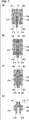
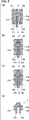
- FIG. 1 is a schematic diagram for explaining a manufacturing process of a conventional general forged crankshaft for a three-cylinder engine.
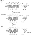
- FIG. 2 schematically shows the shapes of the raw material to be molded by the molding apparatus, the finished punching material, and the finishing material after finishing punching in the manufacturing method of the first embodiment of the present invention.
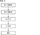
- FIG. 3 is a schematic diagram showing a manufacturing process of the forged crankshaft for a three-cylinder engine in the first embodiment of the present invention.
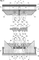
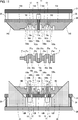
- FIG. 4 is a longitudinal sectional view showing the configuration of the molding apparatus in the first embodiment of the present invention.
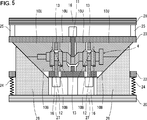
- FIG. 5 is a longitudinal sectional view for explaining a method of forming a finishing material by the forming apparatus according to the first embodiment of the present invention shown in FIG.
- FIG. 6 is a longitudinal sectional view for explaining a method of forming a finishing material by the forming apparatus according to the first embodiment of the present invention shown in FIG. 4, and shows a state when the forming is completed.
- FIG. 7 is a diagram for explaining a situation in which biting occurs in forming a finishing material by the forming apparatus of the present invention.
- FIG. 8 is a diagram for explaining a situation when a countermeasure for biting is applied in forming a finishing material by the forming apparatus of the present invention.
- FIG. 9 shows a rough material to be molded by a molding apparatus, a finished punching material, a finishing material after finishing, and a torsion finishing material after torsion molding in the manufacturing method of the second embodiment of the present invention. It is a figure which shows typically each shape of.
- FIG. 10 is a schematic diagram showing a manufacturing process of a forged crankshaft for a three-cylinder engine in the second embodiment of the present invention.
- FIG. 11 is a longitudinal sectional view showing the configuration of the molding apparatus in the second embodiment of the present invention.
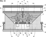
- FIG. 12 is a longitudinal sectional view for explaining a method of forming a finishing material by the forming apparatus according to the second embodiment of the present invention shown in FIG. 11, and shows a state in the initial stage of forming.
- FIG. 10 is a schematic diagram showing a manufacturing process of a forged crankshaft for a three-cylinder engine in the second embodiment of the present invention.
- FIG. 11 is a longitudinal sectional view showing the configuration of the molding apparatus in the second
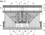
- FIG. 13 is a longitudinal sectional view for explaining a method of forming a finishing material by the forming apparatus according to the second embodiment of the present invention shown in FIG. 11, and shows a state when the forming is completed.
- FIG. 14 schematically shows each shape of a rough material to be molded by a molding apparatus, a finished finishing material, and a finishing material after finishing punching in the manufacturing method of the third embodiment of the present invention.
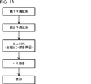
- FIG. 15 is a schematic diagram illustrating a manufacturing process of a forged crankshaft for a three-cylinder engine according to a third embodiment of the present invention.
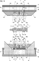
- FIG. 16 is a longitudinal sectional view showing a configuration of a molding apparatus according to the third embodiment of the present invention.
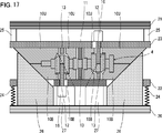
- FIG. 17 is a longitudinal sectional view for explaining a method of forming a finishing material by the forming apparatus according to the third embodiment of the present invention shown in FIG. 16, and shows a state in the initial stage of forming.
- FIG. 18 is a longitudinal sectional view for explaining a method of forming a finishing material by the forming apparatus of the third embodiment of the present invention shown in FIG. 16, and shows a state at the time of completion of forming.
- FIG. 19 schematically shows each shape of a rough material to be molded by a molding apparatus, a finished finishing material, and a finishing material after finishing punching in the manufacturing method of the fourth embodiment of the present invention.
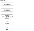
- FIG. FIG. 20 is a schematic diagram showing a manufacturing process of a forged crankshaft for a three-cylinder engine in the fourth embodiment of the present invention.
- the molding apparatus of the present invention is used for the finishing in the pre-finishing process. Used to form finishing materials from coarse materials.
- the embodiment of the forging material for finishing crankshaft for a three-cylinder engine according to the present invention and a method for producing a forged crankshaft for a three-cylinder engine including a pre-forming step using the same are described in detail. To do.
- FIG. 2 shows a rough material to be molded by a molding apparatus and molding in the manufacturing method according to the first embodiment of the present invention. It is a figure which shows typically each shape of the finished material for finishing and the finishing material after finishing. This figure illustrates the situation when manufacturing a crankshaft with 3 cylinders and 4 counterweights. To facilitate understanding of the shape of each stage, a plan view showing the appearance and along the axial direction are shown. The layout of the pin part when viewed is displayed side by side.
- the rough material 4 of the first embodiment has a rough crankshaft shape as a whole while relying on the shape of the forged crankshaft 1 of the three-cylinder / four-piece counterweight shown in FIG. 1 (f).
- Coarse crank arm portions hereinafter also simply referred to as “coarse arm portions” A1a to A6a are included.
- the coarse material 4 has no burrs.
- the finish punching material 5 is formed from the above-described rough material 4 by a molding apparatus, which will be described in detail later, and includes four rough journal portions J1b to J4b and three rough pin portions P1b to P3b. , Rough front portion Frb, rough flange portion Flb, and six rough crank arm portions (hereinafter also simply referred to as “rough arm portions”) A1b to A6b connecting the rough journal portions J1b to J4b and the rough pin portions P1b to P3b, respectively. Consists of The finishing material 5 has no burrs.
- the reference numerals are “Jb” for the rough journal portion and the rough pin portion. “Pb” and “Ab” on the rough arm.
- the finishing material 6 of the first embodiment is obtained by finishing the above-described finishing material 5 and includes four journal portions J1c to J4c, three pin portions P1c to P3c, a front portion Frc, and a flange portion.
- Flc and six crank arm portions (hereinafter also simply referred to as “arm portions”) A1c to A6c connecting the journal portions J1c to J4c and the pin portions P1c to P3c, respectively.
- arm portions six crank arm portions (hereinafter also simply referred to as “arm portions”) A1c to A6c connecting the journal portions J1c to J4c and the pin portions P1c to P3c, respectively.
- the reference numerals are “Jc” for the journal portion, “Pc” for the pin portion, and the arm portion. Is written as “Ac”.
- the shape of the finishing material 6 matches the shape of the crankshaft (final forged product) including the arrangement angle of the pin portion Pc, and corresponds to the forged crankshaft 1 shown in FIG. That is, the journal portion Jc of the finishing material 6 has the same axial length as the journal portion J of the final shape forged crankshaft.
- the pin portion Pc of the finishing material 6 has the same axial length as the pin portion P of the final shape forged crankshaft. Further, the pin portion Pc of the finishing material 6 has the same eccentric amount in the direction perpendicular to the axial direction and the same arrangement angle of 120 ° with respect to the pin portion P of the forged crankshaft of the final shape, and the normal position Is arranged.
- the arm portion Ac of the finishing material 6 has the same axial thickness as the arm portion A of the final shape forged crankshaft.
- the shape of the finishing material 5 is almost the same as the shape of the finishing material 6, and corresponds to the portion excluding the burr 105a of the rough forging material 105 shown in FIG. That is, the coarse journal portion Jb of the finishing material 5 has the same axial length as the journal portion J of the final shape forged crankshaft (the journal portion Jc of the finishing material 6).
- the rough pin portion Pb of the finishing material 5 has the same axial length as the pin portion P of the final shape forged crankshaft (the pin portion Pc of the finishing material 6).
- the pin portion Pb of the finish punching material 5 has the same eccentricity in the direction perpendicular to the axial direction with respect to the pin portion P of the final shape forged crankshaft, and the arrangement angle is also the same 120 °. It is arranged at the position.
- the rough arm portion Ab of the finishing material 5 has the same axial thickness as the arm portion A of the final shape forged crankshaft (the arm portion Ac of the finishing material 6).
- the coarse journal portion Ja of the coarse material 4 has the same axial length as the coarse journal portion Jb of the finishing material 5, that is, the journal portion J of the forged crankshaft (the journal portion Jc of the finish material 6). It is.
- the coarse pin portion Pa of the coarse material 4 has the same axial length as the coarse pin portion Pb of the finish punching material 5, that is, the pin portion P of the forged crankshaft (the pin portion Pc of the finish material 6). The amount of eccentricity is smaller than the rough pin portion Pb of the finish punching material 5.
- the eccentric amounts of the first and third coarse pin portions P1a and P3a at both ends of the coarse pin portion Pa of the coarse material 4 are in the opposite directions to the eccentric amount of the pin portion P of the forged crankshaft. ⁇ 3 / 2.
- the eccentric amount of the center second coarse pin portion P2a is 1 / of the eccentric amount of the pin portion P of the forged crankshaft in a direction orthogonal to the eccentric directions of the first and third coarse pin portions P1a and P3a. It is supposed to be about 2.
- the coarse arm portion Aa of the coarse material 4 is thicker in the axial direction than the coarse arm portion Ab of the finish punching material 5, that is, the arm portion A of the forged crankshaft (the arm portion Ac of the finish material 6).
- the rough material 4 is longer than the finish punching material 5 (final shape forged crankshaft and finishing material 6) by the thicker rough arm portion Aa, and the rough pin portion Pa is uneven.
- the core amount is small and the crankshaft has a relatively gentle shape.
- the finish punching material 5 has the coarse arm portion Ab slightly thinner than the final shape of the forged crankshaft and the finish material 6, and the coarse journal portion Jb and the coarse pin portion correspondingly.
- the axial length of Pb is slightly increased. This is because it is easy to accommodate the finishing material 5 in the mold at the time of finishing and prevent the occurrence of galling.
- the axial lengths of the coarse journal portion J ′ and the coarse pin portion P ′ are also slightly increased in the coarse material 4 with respect to the final shape of the forged crankshaft and the finishing material 6.
- FIG. 3 is a schematic diagram showing a manufacturing process of the forged crankshaft for a 3-cylinder engine according to the first embodiment of the present invention.
- the method for manufacturing a forged crankshaft according to the first embodiment includes steps of first preforming, second preforming, and finishing, and if necessary, steps of deburring and shaping. including.
- the first pre-molding step is a step of modeling the above-described rough material 4.
- a round billet having a round cross section is used as a raw material, and the round billet is heated by an induction heating furnace or a gas atmosphere heating furnace and then subjected to a preforming process to form the rough material 4.
- a round billet is drawn and rolled by a perforated roll and its volume is distributed in the longitudinal direction, and the roll waste obtained thereby is partially pressed down from the direction perpendicular to the longitudinal direction to obtain its volume. If the bending to distribute the number of times is repeated, the rough material 4 can be formed.
- the rough material 4 can be shaped using the techniques disclosed in Patent Documents 1 and 2. Moreover, you may employ
- the second pre-molding step is a step of molding the finishing material 5 described above.
- the finish punching material 5 in which the final shape of the forged crankshaft including the arrangement angle of the pin portion is formed from the above rough material 4 is formed. Can be molded.
- Finishing process is a process for obtaining the finishing material 6 described above.
- the above-mentioned finishing punching material 5 is provided, and the final shape of the forged crankshaft including the arrangement angle of the pin portion is formed by press forging using a pair of upper and lower dies.
- a finishing material 6 having a shape that matches the axis can be obtained.
- FIG. 4 is a longitudinal sectional view showing the structure of the forming apparatus in the first embodiment of the present invention.
- This figure illustrates a molding apparatus for producing a crankshaft of a three-cylinder / four-counterweight, that is, a molding apparatus for molding the finishing material 5 from the raw material 4 shown in FIG.
- the first and third rough pin portions are actually located either on the front side of the paper and on the other side, but for convenience, It is shown on the same plane.
- the molding apparatus uses a press machine, and has a fixed lower hard plate 20 serving as a foundation and an upper hard plate 21 that descends as the ram of the press machine is driven.
- a lower mold support base 22 is elastically supported directly above the lower hard plate 20 via an elastic member 24, and the lower mold support base 22 is allowed to move in the vertical direction.
- the elastic member 24 a disc spring, a coil spring, an air spring, or the like can be applied, and a hydraulic spring system can also be applied.
- An upper mold support base 23 is fixed directly below the upper hard plate 21 via a support column 25.
- the upper mold support base 23 is integrated with the upper hard plate 21 by driving of a press machine (ram). Descend.
- the coarse material 4 is placed in the mold in a posture in which the first and third coarse pin portions P1a and P3a are horizontally arranged and the second coarse pin portion P2a is arranged downward in the vertical direction. Accommodates and molds into a finishing material. For this reason, the lower mold support base 22 and the upper mold support base 23 are divided along the axial direction of the coarse material 4 and are respectively paired with the upper and lower journal molds 10U and 10B, and the reference pin mold 11 and The auxiliary pin mold 13, the movable pin mold 12 and the auxiliary pin mold 13 are attached.
- the reference pin mold 11 and the auxiliary pin mold 13 that form a pair in the upper and lower positions are positions of one rough pin portion Pa serving as a reference among the rough pin portions Pa in the rough material 4, for example, in FIG. It arrange
- the reference pin mold 11 of the first embodiment is disposed on the side opposite to the normal position of one rough pin portion Pa serving as a reference, and the other auxiliary pin mold 13 is a rough pin thereof. It is arranged outside the part Pa which is the normal position.
- the arrangement of the second rough pin portion P2a is on the lower side, and the normal position thereof is also on the lower side.
- the auxiliary pin mold 13 which is attached to the lower mold support base 22 is attached to the lower mold support base 22.
- the reference pin mold 11 and the auxiliary pin mold 13 are restrained from moving in the axial direction with respect to the upper mold support base 23 and the lower mold support base 22 in both the upper and lower sides. Only the reference pin mold 11 is allowed to move in a direction perpendicular to the axial direction and toward the normal position of the coarse pin portion Pa (downward direction in FIG. 4).
- the reference pin mold 11 and the auxiliary pin mold 13 are formed with semi-cylindrical engraved portions 11a and 13a, respectively.
- the lengths of the engraved portions 11a and 13a are the same as the length in the axial direction of the second rough pin portion P2b in the finishing material 5.
- the engraving portion 11a is assigned to the second rough pin portion P2a by the lowering of the upper die support base 23 accompanying the drive of the press machine, that is, the press machine press, and both side surfaces of the reference pin mold 11 are Are in contact with the side surfaces of the third and fourth rough arm portions A3a and A4a connected to the second rough pin portion P2a on the second rough pin portion P2a side.
- the movable pin mold 12 and the auxiliary pin mold 13 that form a pair in the upper and lower positions are positions of the coarse pin portions Pa other than the coarse pin portion Pa to which the reference pin mold 11 is addressed, for example, in FIG. It arrange
- the movable pin mold 12 of the first embodiment is disposed on the side opposite to the side where the rough pin portion Pa is a normal position, and the other auxiliary pin mold 13 is the normal pin of the rough pin portion Pa. It is arranged outside the position side.
- the movable pin mold 12 is attached to the lower mold support base 22 and is paired with this.
- the auxiliary pin mold 13 to be formed is attached to the upper mold support base 23.
- the movable pin mold 12 and the auxiliary pin mold 13 are allowed to move in the axial direction toward the reference pin mold 11 with respect to the lower mold support base 22 and the upper mold support base 23 in both the upper and lower sides. ing. Only the movable pin type 12 is allowed to move in a direction perpendicular to the axial direction and toward the normal position of the coarse pin portion Pa (upward direction in FIG. 4).
- the movable pin mold 12 and the auxiliary pin mold 13 are formed with semi-cylindrical engraved portions 12a and 13a, respectively.
- the lengths of the engraved portions 12a and 13a are the same as the lengths in the axial direction of the rough pin portions Pb in the finishing material 5 for finishing.
- the journal molds 10U and 10B are arranged at the position of the coarse journal portion Ja in the coarse material 4, and the upper and lower parts are attached to the upper mold support base 23 and the lower mold support base 22, respectively.
- the journal molds 10U and 10B are allowed to move in the axial direction toward the reference pin mold 11 with respect to the upper mold support base 23 and the lower mold support base 22 in both upper and lower sides.
- the journal molds 10U and 10B include semi-cylindrical first engraved portions 10Ua and 10Ba, and second engraved portions 10Ub and 10Bb adjacent to the front and rear (left and right in FIG. 4) of the first engraved portions 10Ua and 10Ba, respectively. Is formed.
- the lengths of the first engraving portions 10Ua and 10Ba are the same as the axial length of the coarse journal portion Jb in the finishing material 5.
- the lengths of the second engraved portions 10Ub and 10Bb are the same as the axial thickness of the coarse arm portion Ab connected to the coarse journal portion Jb in the finishing material 5.
- the journal molds 10U and 10B are respectively held by holding the coarse journal portions Ja from above and below by the first engraving portions 10Ua and 10Ba by the lowering of the upper die support base 23 accompanying the drive of the press machine, that is, the pressure of the press machine. To do.
- the journal molds 10U and 10B are provided on the side of each coarse journal portion Ja in the coarse arm portion Aa where the surface of the second engraved portion 10Ub and 10Bb on the first engraved portion 10Ua and 10Ba side is connected to each coarse journal portion Ja. It will be in the state which contacted the side.
- the reference pin mold 11 and the movable pin mold 12 are moved so that the engraved portions 11a and 12a are directed to the rough pin portions Pa by the lowering of the upper die support base 23 accompanying the drive of the press machine, that is, the press machine is pressed.
- both side surfaces of the reference pin type 11 and the movable pin type 12 are brought into contact with the side surfaces of the rough arm portions Aa connected to the rough pin portions Pa on the side of the rough pin portions Pa.
- the end surfaces of the journal molds 10U and 10B arranged at the positions of the first and fourth coarse journal portions J1a and J4a at both ends are inclined surfaces 14U and 14B.
- the first and fourth coarse journal portions J1a and J4a are individually provided in correspondence with the positions of the inclined surfaces 14U and 14B of the journal dies 10U and 10B.
- a wedge 26 is erected, and each first wedge 26 protrudes upward through the lower mold support base 22.
- the inclined surface 14B of the lower journal dies 10B is in contact with the inclined surface of the first wedge 26 in the initial state.
- the inclined surface 14U of the upper journal mold 10U is brought into contact with the inclined surface of the first wedge 26 by the lowering of the upper mold support base 23 accompanying the drive of the press machine, that is, the press machine being pressed.
- journal molds 10U and 10B arranged at the positions of the second and third coarse journal portions J2a and J3a closer to the center include side portions that are separated from the first engraved portions 10Ua and 10Ba and the second engraved portions 10Ub and 10Bb.
- a block (not shown) having the inclined surfaces 15U and 15B is fixed (in FIG. 4, in front of and behind the page).
- the second and third coarse journal portions J2a and J3a are individually provided in correspondence with the positions of the inclined surfaces 15U and 15B of the journal molds 10U and 10B.
- a wedge 27 is erected, and each second wedge 27 protrudes upward through the lower mold support base 22.
- the inclined surface 15B of the lower journal dies 10B is in contact with the inclined surface of the second wedge 27 in the initial state.
- the inclined surface 15U of the upper journal mold 10U is brought into contact with the inclined surface of the second wedge 27 by the lowering of the upper mold support base 23 accompanying the driving of the pressing machine, that is, the pressing of the pressing machine.
- journal molds 10U, 10B of the first and fourth coarse journal portions J1a, J4a have their inclined surfaces 14U, 14B slide along the inclined surface of the first wedge 26, both above and below. It moves in the axial direction toward the reference pin mold 11 of the second rough pin portion P2a serving as a reference.
- the journal types 10U and 10B of the second and third coarse journal portions J2a and J3a have their inclined surfaces 15U and 15B slide along the inclined surface of the second wedge 27, both above and below. It moves in the axial direction toward the reference pin mold 11 of the second rough pin portion P2a serving as a reference.
- the journal molds 10U and 10B can be individually moved in the axial direction by a wedge mechanism.
- the movable pin mold 12 and the auxiliary pin mold 13 are pushed down together as the press machine continues to be reduced. Thereby, the movable pin mold 12 and the auxiliary pin mold 13 are directed toward the reference pin mold 11 of the second rough pin portion P2a serving as a reference as the journal molds 10U and 10B move in the axial direction as described above. To move in the axial direction. Further, the movement of the reference pin mold 11 and the movable pin mold 12 in the direction perpendicular to the axial direction is performed by driving the hydraulic cylinders 16 connected to the pin molds 11 and 12.
- the movable pin mold 12 and the auxiliary pin mold 13 are forcibly moved in the axial direction by using a wedge mechanism similar to the journal molds 10U and 10B, a separate mechanism such as a hydraulic cylinder or a servo motor. May be.
- the auxiliary pin mold 13 may be integrated with one of a pair of adjacent journal molds 10U and 10B.
- journal molds 10U and 10B In the initial state shown in FIG. 4, in order to allow the axial movement of the journal molds 10U and 10B, and the movable pin mold 12 and the auxiliary pin mold 13, the journal molds 10U and 10B individually linked in the axial direction, and the reference A gap is secured between the pin type 11, the movable pin type 12, and the auxiliary pin type 13.
- the size of each gap is the difference between the thickness of the coarse arm portion Ab in the finish punching material 5 and the thickness of the coarse arm portion Aa in the coarse material 4.
- FIG. 5 and 6 are longitudinal sectional views for explaining a method of forming a finishing material by the forming apparatus according to the first embodiment of the present invention shown in FIG. 4, and FIG. 6 shows the state when the molding is completed.
- the raw material 4 is accommodated in the lower journal die 10B, the movable pin die 12 and the auxiliary pin die 13 shown in FIG. 4, and the press of the press machine is started. Then, as shown in FIG. 5, the upper journal mold 10U first comes into contact with the lower journal mold 10B.
- each coarse journal portion Ja is held from above and below by the journal dies 10U and 10B, and the reference pin die 11 and the movable pin die 12 are assigned to each coarse pin portion Pa.
- the journal molds 10U and 10B are in contact with the side surface of the coarse journal portion Ja side of each coarse arm portion Aa of the coarse material 4, and the side surface of the coarse pin portion Pa side of each coarse arm portion Aa is The reference pin mold 11 and the movable pin mold 12 are in contact.
- the inclined surfaces 14U and 14B of the journal molds 10U and 10B of the first and fourth coarse journal portions J1a and J4a are in contact with the inclined surface of the first wedge 26, and the second and third coarse journal portions J2a.
- the inclined surfaces 15U and 15B of the journal molds 10U and 10B of J3a are in contact with the inclined surface of the second wedge 27.
- the coarse material 4 has the coarse arm portion Aa maintained while the axial lengths of the coarse journal portion Ja and the coarse pin portion Pa are maintained by the journal dies 10U and 10B, the reference pin die 11 and the movable pin die 12.
- the thickness of the rough arm portion Aa is reduced to the thickness of the rough arm portion Ab of the finish punching material 5 (see FIG. 6).
- mold 11 and 12 presses the rough pin part Pa of the coarse raw material 4 in the direction orthogonal to an axial direction individually.
- the eccentric amount thereof is increased to the eccentric amount of the coarse pin portion Pb of the finish punching material 5.
- Coarse pin part Pb will also be in the state arrange
- the finish punching material 5 having no burr and having a shape substantially matching the shape of the forged crankshaft (final forged product) for the three-cylinder engine having the thin arm portion A from the rough material 4 having no burr is obtained.
- the final shape of the forged crankshaft can be shaped. Accordingly, a forged crankshaft for a three-cylinder engine can be manufactured with high yield and high dimensional accuracy regardless of its shape. However, if a portion corresponding to the balance weight is formed on the arm portion at the stage of the coarse material, a forged crankshaft having a balance weight can be manufactured.
- the inclination angles of the inclined surfaces 14U and 14B of the journal molds 10U and 10B of the portion J4a and the inclined surfaces of the first wedges 26 in contact with the journal surfaces 10U and 10B are opposite to each other on the basis of the vertical surface.
- the inclination angle of 15B and the inclined surface of the second wedge 27 in contact therewith are opposite to each other with respect to the vertical plane.
- the angle of the inclined surface of the first wedge 26 (the angle of the inclined surfaces 14U and 14B of the journal molds 10U and 10B of the first and fourth coarse journal portions J1a and J4a) is the angle of the inclined surface of the second wedge 27 (second The angle of the inclined surfaces 15U and 15B of the journal types 10U and 10B of the third coarse journal portions J2a and J3a.
- the reason why the wedge angle of the wedge mechanism for moving each journal mold 10U, 10B in the axial direction is different for each journal mold 10U, 10B is that the coarse arm portion Aa is pinched in the axial direction to reduce the thickness. This is to keep the deformation speed to be constant in all the coarse arm portions Aa.
- the rough material 4 used in the molding apparatus shown in FIGS. 4, 5, and 6 has a cross-sectional area of the rough journal portion Ja, which is the cutting of the rough journal portion Jb of the finish punching material 5, that is, the journal portion J of the forged crankshaft. It is equal to or larger than the area.
- the cross-sectional area of the rough pin portion Pa of the rough material 4 is the same as or larger than the cross-sectional area of the rough pin portion Pb of the finish punching material 5, that is, the pin portion P of the forged crankshaft.
- the cross-sectional area of the coarse journal portion Ja of the coarse material 4 is larger than the cross-sectional area of the coarse journal portion Jb of the finish punching material 5, and the cross-sectional area of the coarse pin portion Pa of the coarse material 4 is the coarse pin portion of the finish punching material 5.
- the coarse journal portion Ja is held and held by the journal dies 10U and 10B, and the journal dies 10U and 10B are moved in the axial direction.
- the cross-sectional area can be reduced to the cross-sectional area of the rough journal portion Jb of the finish punching material 5, and in addition to the movement of the reference pin mold 11 in the direction perpendicular to the axial direction, the movable pin mold 12 moves in the axial direction. With the movement in the direction perpendicular to this, the cross-sectional area of the rough pin portion Pa can be reduced to the cross-sectional area of the rough pin portion Pb of the finishing material 5.
- FIG. 7 is a diagram for explaining a situation in which biting occurs in the molding of the finishing material by the molding apparatus of the present invention
- FIG. 8 is a diagram for explaining the situation when the countermeasure is taken.
- FIG. 7 and 8 (a) shows the initial state of molding, (b) shows the state during the molding, (c) shows the state when the molding is completed, and (d) shows the state after the molding is completed. Each finishing material is shown.
- the biting part 5a is driven into the product in the finishing process of the next process and becomes a fogger. Therefore, it is necessary to prevent the occurrence of biting from the viewpoint of ensuring product quality.
- a rough pin portion Pa that is pressed and deformed after the gaps between the journal dies 10U and 10B and the reference pin die 11, the movable pin die 12 and the auxiliary pin die 13 are closed.
- the movement of the reference pin mold 11 and the movable pin mold 12 in the direction perpendicular to the axial direction may be controlled so as to reach the auxiliary pin mold 13.
- the reference pin mold 11 and the movable pin mold 12 are completed. What is necessary is just to complete the movement to the direction orthogonal to the axial direction of.
- the journal molds 10U and 10B adjacent to the pin molds 11 and 12 move in the axial direction.
- the movement distance in the direction perpendicular to the axial direction of the pin molds 11 and 12 is 90% or less (more preferably 83% or less, more preferably 60% or less) of the total movement distance, After this, it is preferable to complete the movement of the pin molds 11 and 12 in that direction.
- the movement distance in the direction perpendicular to the axial direction of the reference pin mold 11 and the movable pin mold 12 is as follows.
- the movement of the journal molds 10U and 10B, the movable pin mold 12 and the auxiliary pin mold 13 in the axial direction is completed until reaching 90% of the total movement distance.
- the gaps between the journal molds 10U and 10B and the reference pin mold 11, the movable pin mold 12, and the auxiliary pin mold 13 are closed, the rough pin portion Pa that is deformed by pressing is changed to the auxiliary pin mold 13. Not reached.
- the movement process in the direction perpendicular to the axial direction of the pin type until the movement in the axial direction of the journal type is completed can be arbitrarily changed.
- the movement in the direction perpendicular to the axial direction of the pin type may start simultaneously with the start of the movement in the axial direction of the journal type, or may start before that, or the axis of the journal type You may start, after the movement to a direction progresses to some extent.
- the movement in a direction perpendicular to the axial direction of the pin type may be temporarily stopped at a position moved by a certain amount after the start, and resumed after the movement in the axial direction of the journal type is completed.
- Second Embodiment is based on the configuration of the first embodiment described above, and a twist forming process is added to the manufacturing process of the forged crankshaft for a three-cylinder engine, and the related configuration is modified. It is.
- FIG. 2 It is a figure which shows typically each shape of the rough raw material made into a shaping
- This figure illustrates the situation when manufacturing a crankshaft of a three-cylinder-6-counterweight.
- FIG. 2 a plan view showing the appearance and a pin when viewed along the axial direction are shown. The layout of the parts is displayed side by side.
- the matter which overlaps with 1st Embodiment is abbreviate
- the rough material 4 of the second embodiment has a rough crankshaft shape as a whole while relying on the shape of the forged crankshaft 1 of the three-cylinder-6-piece counterweight, and has four rough journal portions.
- Ja comprises three rough pin portions Pa, a rough front portion Fra, a rough flange portion Fla, and six rough arm portions Aa.
- the finish punching material 5 according to the second embodiment is formed from the above-described rough material 4 by a molding device, which will be described in detail later, and includes four rough journal portions Jb, three rough pin portions Pb, and a rough front portion. Frb, coarse flange part Flb, and six coarse arm parts Ab are comprised.
- the finishing material 6 of the second embodiment is obtained by finishing the above-described finishing material 5 and includes four journal portions Jc, three pin portions Pc, a front portion Frc, a flange portion Flc, and 6. It consists of a single arm portion Ac.
- the torsional finishing material 7 of the second embodiment is obtained by twisting the finishing material 6 described above, and includes four journal parts J1d to J4d, three pin parts P1d to P3d, a front part Frd, and a flange part Fld. And six crank arm portions (hereinafter also simply referred to as “arm portions”) A1d to A6d connecting the journal portions J1d to J4d and the pin portions P1d to P3d, respectively.
- journal portions J1d to J4d, the pin portions P1d to P3d, and the arm portions A1d to A6d of the torsion finish 7 are collectively referred to, the reference numerals are “Jd” for the journal portion, “Pd” for the pin portion, and the arm. "Ad” in the part.
- the shape of the twisted finish 7 matches the shape of the crankshaft (final forged product) including the arrangement angle of the pin portion Pd. That is, the journal portion Jd of the twisted finish 7 has the same axial length as the journal portion J of the final shape forged crankshaft.
- the pin portion Pd of the twisted finish 7 has the same axial length as the pin portion P of the final shape forged crankshaft.
- the pin portion Pd of the torsion finishing material 7 has the same eccentricity in the direction perpendicular to the axial direction and the same arrangement angle of 120 ° with respect to the pin portion P of the final shape forged crankshaft. Placed in position.
- the arm portion Ad of the twisted finish 7 has the same axial thickness as the arm portion A of the final shape forged crankshaft.
- the shape of the finishing material 6 matches the shape of the crankshaft (final forged product) except for the arrangement angle of the pin portion Pc. That is, the journal portion Jc of the finishing material 6 has the same axial length as the journal portion J of the final shape forged crankshaft.
- the pin portion Pc of the finishing material 6 has the same length in the axial direction as the pin portion P of the final shape forged crankshaft, and the amount of eccentricity in the direction perpendicular to the axial direction is also the same. However, the arrangement angle of the pin portion Pc of the finishing material 6 deviates from the normal position.
- the first and third pin portions P1c and P3c at both ends are eccentric in the same direction in a direction perpendicular to the axial direction, and the second pin portion P2c at the center. Are eccentric in the direction opposite to the eccentric direction of the first and third pin portions P1c, P3c.
- the arm portion Ac of the finishing material 6 has the same axial thickness as the arm portion A of the final shape forged crankshaft.
- the shape of the finishing material 5 generally matches the shape of the finishing material 6. That is, the coarse journal portion Jb of the finishing material 5 has the same axial length as the journal portion J of the final shape forged crankshaft (the journal portion Jc of the finishing material 6).
- the rough pin portion Pb of the finishing material 5 has the same axial length as the pin portion P of the final shape forged crankshaft (the pin portion Pc of the finishing material 6), and a direction perpendicular to the axial direction.
- the amount of eccentricity is also the same, but the arrangement angle is deviated from the normal position as with the finishing material 6.
- the rough arm portion Ab of the finishing material 5 has the same axial thickness as the arm portion A of the final shape forged crankshaft (the arm portion Ac of the finishing material 6).
- the coarse journal portion Ja of the coarse material 4 has the same axial length as the coarse journal portion Jb of the finishing material 5, that is, the journal portion J of the forged crankshaft (the journal portion Jc of the finish material 6). It is.
- the coarse pin portion Pa of the coarse material 4 has the same axial length as the coarse pin portion Pb of the finish punching material 5, that is, the pin portion P of the forged crankshaft (the pin portion Pc of the finish material 6). The amount of eccentricity is smaller than the rough pin portion Pb of the finish punching material 5.
- the eccentric amount of the first and third coarse pin portions P1a and P3a at both ends of the coarse pin portion Pa of the coarse material 4 is the same as the eccentric amount of the pin portion P of the forged crankshaft. It is about 1/2.
- the eccentric amount of the center second coarse pin portion P2a is 1 ⁇ 2 of the eccentric amount of the pin portion P of the forged crankshaft in the direction opposite to the eccentric direction of the first and third coarse pin portions P1a, P3a. It is said to be about.
- the coarse arm portion Aa of the coarse material 4 is thicker in the axial direction than the coarse arm portion Ab of the finish punching material 5, that is, the arm portion A of the forged crankshaft (the arm portion Ac of the finish material 6).
- FIG. 10 is a schematic diagram showing a manufacturing process of a forged crankshaft for a 3-cylinder engine according to the second embodiment of the present invention.
- the method for manufacturing a forged crankshaft according to the second embodiment includes the steps of first preforming, second preforming, finish punching, and twisting, and if necessary, before twisting. Each process of deburring and shaping after torsion molding is included.
- the first pre-molding step is a step of modeling the above-described rough material 4.
- 5 is a step of molding 5.
- the finish punching step is a step of obtaining the above finish material 6 in which the finish punching material 5 is provided and the final shape of the forged crankshaft is formed except for the arrangement angle of the pin portion.
- the twist forming process is a process for obtaining the above-described twist finish material 7.
- the pin portion is arranged at the angle of the pin portion of the forged crankshaft by twisting the journal portion around the shaft center while holding the journal portion and the pin portion of the finishing material 6 described above. It is possible to obtain a torsion finish 7 having a shape that matches the crankshaft, in which the final shape of the forged crankshaft including the pin portion arrangement angle is formed.
- FIG. 11 is a longitudinal sectional view showing the structure of the forming apparatus in the second embodiment of the present invention.
- the figure illustrates a molding apparatus for manufacturing a crankshaft of a three-cylinder-6-counterweight, that is, a molding apparatus for molding the finishing material 5 from the raw material 4 shown in FIG.
- the vertical cross section shown in the figure actually includes all the rough pin portions on the same plane.
- the coarse material 4 is aligned with the eccentric direction of the coarse pin portion Pa in the vertical direction, for example, the first and third coarse pin portions P1a and P3a are arranged on the top. Then, the second rough pin portion P2a is accommodated in the mold in a posture arranged below, and is formed into the finishing material 5 for finishing. Since the configuration other than this point is the same as that of the molding apparatus of the first embodiment shown in FIG.
- FIG. 12 and 13 are longitudinal sectional views for explaining a method of forming a finishing material by the forming apparatus according to the second embodiment of the present invention shown in FIG. 11, and FIG. Reference numeral 13 denotes a state when the molding is completed.
- the journal die 10U holding each coarse journal portion Ja. 10B moves in the axial direction toward the reference pin mold 11 addressed to the second rough pin portion P2a, and accordingly, the movable addressed to the first and third rough pin portions P1a and P3a.
- the pin mold 12 and the auxiliary pin mold 13 also move in the axial direction toward the reference pin mold 11.
- the coarse material 4 has the coarse arm portion Aa while the axial lengths of the coarse journal portion Ja and the coarse pin portion Pa are maintained by the journal dies 10U and 10B, the reference pin die 11 and the movable pin die 12. Is clamped in the axial direction, and the thickness of the coarse arm portion Aa is reduced to the thickness of the coarse arm portion Ab of the finishing material 5 (see FIG. 13).
- the reference pin mold 11 and the movable pin mold 12 are individually moved along with the driving of the respective hydraulic cylinders 16.
- the coarse pin portion Pa of the coarse material 4 is pressed in a direction perpendicular to the axial direction.
- the eccentric amount of the coarse pin portion of the finish punching material 5 is maintained even though the arrangement angle deviates from the normal position. It will be in the state increased to the eccentric amount of Pb (refer FIG. 9, FIG. 13).
- the rough material 4 without burrs except for the arrangement angle of the pin portion P, has a shape that roughly matches the shape of the forged crankshaft (final forged product) for a three-cylinder engine with a thin arm portion A.
- the finishing material 5 without burrs can be formed.
- the contour shape of the arm portion 3 is included.
- the finishing material 6 having the final shape of the forged crankshaft for the cylinder engine can be formed.
- the final shape of the forged crankshaft for a three-cylinder engine can be formed, including the arrangement angle of the pin portion. Accordingly, a forged crankshaft for a three-cylinder engine can be manufactured with high yield and high dimensional accuracy regardless of its shape.
- the third embodiment is based on the configuration of the first and second embodiments described above, and the cranking is performed in the finish punching process without adding a twist forming process to the manufacturing process of the forged crankshaft for a three-cylinder engine. In order to form the final shape of the shaft intentionally, the related configuration is modified.
- FIG. 14 shows a rough material to be molded by the molding apparatus and molding in the manufacturing method of the third embodiment of the present invention. It is a figure which shows typically each shape of the finished material for finishing and the finishing material after finishing. In the figure, the situation in the case of manufacturing a crankshaft of 3 cylinders and 4 counterweights is illustrated.
- the coarse material 4 of the third embodiment has a rough crankshaft shape as a whole while relying on the shape of the forged crankshaft 1 of the three-cylinder / four-piece counterweight, and has four coarse journal portions.
- Ja comprises three rough pin portions Pa, a rough front portion Fra, a rough flange portion Fla, and six rough arm portions Aa.
- the finish punching material 5 according to the third embodiment is formed from the above-described rough material 4 by a molding device, which will be described in detail later, and includes four rough journal portions Jb, three rough pin portions Pb, and a rough front portion. Frb, coarse flange part Flb, and six coarse arm parts Ab are comprised.
- the finishing material 6 according to the third embodiment is obtained by finishing the finishing material 5 described above, and includes four journal portions Jc, three pin portions Pc, a front portion Frc, a flange portion Flc, and 6. It consists of a single arm portion Ac.
- the shape of the finishing material 6 matches the shape of the crankshaft (final forging product) including the arrangement angle of the pin portion Pc. That is, the journal portion Jc of the finishing material 6 has the same axial length as the journal portion J of the final shape forged crankshaft.
- the pin portion Pc of the finishing material 6 has the same axial length as the pin portion P of the final shape forged crankshaft. Further, the pin portion Pc of the finishing material 6 has the same eccentric amount in the direction perpendicular to the axial direction and the same arrangement angle of 120 ° with respect to the pin portion P of the forged crankshaft of the final shape, and the normal position Is arranged.
- the arm portion Ac of the finishing material 6 has the same axial thickness as the arm portion A of the final shape forged crankshaft.
- the rough journal portion Jb of the finishing material 5 has the same axial length as the journal portion Jc of the finishing material 6, that is, the journal portion J of the forged crankshaft.
- the rough pin portion Pb of the finishing material 5 has the same axial length as the pin portion Pc of the finishing material 6, that is, the pin portion P of the forged crankshaft, but the eccentricity and the arrangement angle are normal positions. It is off.
- the eccentric amounts of the first and third rough pin portions P1b and P3b at both ends of the rough pin portion Pb of the finish punching material 5 are offset in the opposite directions to each other. It is the same as ⁇ 3 / 2 of the core amount.
- the center second coarse pin portion P2b is not eccentric, and the amount of eccentricity is zero.
- the rough arm portion Ab of the finishing material 5 has the same axial thickness as the arm portion A of the final shape forged crankshaft (the arm portion Ac of the finishing material 6).
- the coarse journal portion Ja of the coarse material 4 has the same axial length as the coarse journal portion Jb of the finishing material 5, that is, the journal portion J of the forged crankshaft (the journal portion Jc of the finish material 6). .
- the coarse pin portion Pa of the coarse material 4 has the same axial length as the coarse pin portion Pb of the finish punching material 5, that is, the pin portion P of the forged crankshaft (the pin portion Pc of the finish material 6).
- the eccentric amount of the first and third coarse pin portions P1a and P3a out of the coarse pin portion Pa of the coarse material 4 is made smaller than that of the finish punching material 5, and the forged crankshafts are in opposite directions. It is smaller than ⁇ 3 / 2 of the eccentric amount of the pin portion P.
- the amount of eccentricity of the second rough pin portion P2a is set to zero, similar to that of the finish punching material 5.
- the coarse arm portion Aa of the coarse material 4 is thicker in the axial direction than the coarse arm portion Ab of the finish punching material 5, that is, the arm portion A of the forged crankshaft (the arm portion Ac of the finish material 6).
- FIG. 15 is a schematic diagram showing a manufacturing process of a forged crankshaft for a 3-cylinder engine according to the third embodiment of the present invention.
- the method for manufacturing a forged crankshaft according to the third embodiment includes steps of first preforming, second preforming, and finishing, and each step of deburring and shaping as necessary. including.
- the first pre-molding step is a step of modeling the above-described rough material 4.
- the final shape of the forged crankshaft was formed from the raw material 4 except for the eccentric amount and the arrangement angle of all the pin portions by using the forming apparatus shown in FIG. This is a step of forming the finishing material 5 described above.
- Finishing process is a process for obtaining the finishing material 6 described above.
- the above-mentioned finish punching material 5 is provided, and in a state where the first and third rough pin portions are horizontally arranged, press forging using a pair of upper and lower dies, All rough pins are pressed in the vertical direction perpendicular to the axial direction.
- the finishing material 6 having a shape that matches the crankshaft, in which the final shape of the forged crankshaft is formed including the arrangement angle of the pin portion.
- FIG. 16 is a longitudinal sectional view showing the structure of the forming apparatus in the third embodiment of the present invention. This figure illustrates a molding apparatus for molding the finishing material 5 from the rough material 4 shown in FIG. The vertical cross section shown in the figure actually includes all the rough pin portions on the same plane.
- the molding apparatus of the third embodiment shown in FIG. 16 is largely different from the molding apparatus of the first embodiment shown in FIG. 4 and the molding apparatus of the second embodiment shown in FIG. 11 in the following points. To do.
- the molding apparatus according to the third embodiment accommodates the coarse material 4 in the mold in a posture in which the first and third coarse pin portions P1a and P3a eccentric in opposite directions are arranged along the vertical direction.
- the material for finishing punching 5 is formed.
- the reference pin mold 11 disposed at the position of the second rough pin portion P2a is restricted not only in the axial direction but also in the direction perpendicular to the axial direction.
- the reference pin mold 11 of the third embodiment is not connected to the hydraulic cylinders as in the first and second embodiments, and is the one of the upper mold support base 23 and the lower mold support base 22. It is attached directly to one side. On the other side, an auxiliary pin mold 13 that is paired with the reference pin mold 11 is directly attached.
- FIG. 16 shows a mode in which the reference pin mold 11 is attached to the upper mold support base 23 and the auxiliary pin mold 13 is attached to the lower mold support base 22.
- the movable pin mold 12 and the auxiliary pin mold 13 disposed at the positions of the first and third rough pin portions P1a and P3a are the first and third rough pin portions P1a, Since P3a is decentered in the opposite direction in the vertical direction, the upper and lower arrangements are switched between the position of the first rough pin portion P1a and the position of the third rough pin portion P3a.
- the auxiliary pin mold 13 at the position of the first rough pin portion P1a and the movable pin mold 12 at the position of the third rough pin portion P3a are arranged on the upper side, and the movable pin mold at the position of the first rough pin portion P1a. 12 and the auxiliary pin mold 13 at the position of the third rough pin portion P3a are shown on the lower side.
- FIG. 17 and 18 are longitudinal sectional views for explaining a method of forming a finishing material by the forming apparatus according to the third embodiment of the present invention shown in FIG. 16, and FIG. Reference numeral 18 denotes a state when the molding is completed.
- the movable pin die 12 and the auxiliary pin die 13 and the press machine is pressed, first, the coarse material 4 is divided into each coarse journal portion. Ja is sandwiched and held from above and below by the journal molds 10U and 10B, and at the same time, the second rough pin portion P2a is sandwiched and held by the reference pin mold 11 and the auxiliary pin mold 13 from the top and bottom.
- the movable pin mold 12 is assigned to the pin portions P1a and P3a.
- the journal molds 10U and 10B holding the respective coarse journal parts Ja move in the axial direction toward the reference pin mold 11 holding the second coarse pin part P2a
- the movable pin mold 12 and the auxiliary pin mold 13 addressed to the first and third rough pin portions P1a and P3a also move in the axial direction toward the reference pin mold 11.
- the coarse material 4 has the coarse arm portion Aa while the axial lengths of the coarse journal portion Ja and the coarse pin portion Pa are maintained by the journal dies 10U and 10B, the reference pin die 11 and the movable pin die 12. Is sandwiched in the axial direction, and the thickness of the coarse arm portion Aa is reduced to the thickness of the coarse arm portion Ab of the finishing material 5 (see FIG. 18).
- each of the movable pin molds 12 is individually moved in accordance with the driving of the hydraulic cylinders 16.
- the first and third rough pin portions P1a and P3a are pressed in the vertical direction perpendicular to the axial direction.
- the first and third rough pin portions P1a and P3a of the coarse material 4 are displaced in the vertical direction perpendicular to the axial direction, so that the eccentric amount of the pin portion P of the forged crankshaft in the opposite direction is ⁇ 3 / 2 is increased to the same eccentricity as 2 (see FIGS. 14 and 18).
- the second rough pin portion P2b of the coarse material 4 is maintained in a state where the position in the direction perpendicular to the axial direction is unchanged before and after molding, and the eccentricity remains zero.
- the finish punching material 5 having no burr can be formed. Then, such a burr-free finishing material 5 is subjected to finishing, and finishing is performed in a state in which the first and third rough pin portions are horizontally arranged.
- the final shape of the forged crankshaft for a three-cylinder engine can be formed including the shape, the eccentric amount of the pin portion, and the arrangement angle. Accordingly, a forged crankshaft for a three-cylinder engine can be manufactured with high yield and high dimensional accuracy regardless of its shape.
- Fourth Embodiment is a modification of the configuration of the third embodiment.
- FIG. 19 shows a rough material to be molded by the molding apparatus and molding in the manufacturing method according to the fourth embodiment of the present invention. It is a figure which shows typically each shape of the finished material for finishing and the finishing material after finishing.
- the finishing material 6 of the fourth embodiment has the same shape as the finishing material 6 of the third embodiment shown in FIG. 19
- the finishing material 5 of the fourth embodiment differs from the finishing material 5 of the third embodiment shown in FIG. 14 in the following points.
- the center second rough pin portion P2b in the finishing material 5 of the fourth embodiment is in a direction perpendicular to the eccentric direction of the first and third rough pin portions P1b and P3b at both ends.
- the eccentricity is made the same as the pin portion Pc of the finishing material 6, that is, the pin portion P of the forged crankshaft.
- the coarse material 4 of the fourth embodiment differs from the coarse material 4 of the third embodiment shown in FIG. 14 in the following points.
- the second coarse pin portion P2b at the center of the coarse material 4 of the fourth embodiment is eccentric in the direction orthogonal to the eccentric directions of the first and third coarse pin portions P1b and P3b at both ends.
- the amount of eccentricity is the same as that of the pin portion P of the forged crankshaft (the pin portion Pc of the finishing material 6), similarly to that of the finish punching material 5.
- FIG. 20 is a schematic diagram showing a manufacturing process of a forged crankshaft for a 3-cylinder engine according to the fourth embodiment of the present invention.
- the method of manufacturing the forged crankshaft of the fourth embodiment includes the steps of the first preforming, the second preforming, and the finishing punching, as in the third embodiment shown in FIG. , Deburring and shaping steps are included as necessary.
- the first pre-molding step is a step of modeling the above-described rough material 4.
- the second pre-molding step is a step of molding the finishing material 5 described above.
- the same molding apparatus as that of the third embodiment shown in FIGS. 16, 17 and 18 is used.
- the portion of the second rough pin portion is actually located in front of or behind the paper.
- the lower journal mold 10B, the movable pin mold 12 and the auxiliary pin mold 13 are made of a rough material. 4 is accommodated and the press machine is reduced.
- the coarse material 4 includes the journal molds 10U and 10B holding the respective coarse journal parts Ja, and the movable pin mold 12 and the auxiliary pin mold 13 addressed to the first and third coarse pin parts P1a and P3a.
- the coarse arm portion Aa is maintained while the axial lengths of the coarse journal portion Ja and the coarse pin portion Pa are maintained as it moves in the axial direction toward the reference pin mold 11 holding the second coarse pin portion P2a. Is clamped in the axial direction, and the thickness of the coarse arm portion Aa is reduced to the thickness of the coarse arm portion Ab of the finishing material 5.
- the movable pin mold 12 presses the first and third rough pin portions P1a and P3a in the vertical direction perpendicular to the axial direction, the first and third rough pin portions P1a and P3a of the coarse material 4 are mutually connected.
- the eccentric amount of the forged crankshaft pin portion P is increased to the same eccentricity as ⁇ 3 / 2, while the second rough pin portion P2b of the raw material 4 is formed by molding.
- the position in the direction perpendicular to the axial direction is maintained unchanged, and the amount of eccentricity remains the same as the amount of eccentricity of the pin portion of the forged crankshaft.
- the forged crankshaft for a three-cylinder engine with the thin arm portion A (final) is removed from the raw material 4 without burrs except for the eccentricity and the arrangement angle of the first and third pin portions P1 and P3.
- the above-described finish punching material 5 without a burr, in which a shape substantially coinciding with the shape of the forged product) can be formed.
- Finishing process is a process for obtaining the finishing material 6 described above.
- the finish punching material 5 is provided, and finish punching is performed in a state in which the first and third rough pin portions are arranged horizontally.
- the first and third rough pin portions P1b and P3b of the finishing material 5 are pressed in the vertical direction perpendicular to the axial direction to be displaced to the normal position, some burrs are generated.
- the finishing material 6 having a shape that matches the crankshaft in which the final shape of the forged crankshaft for a three-cylinder engine is formed including the contour shape of the arm portion, the eccentric amount of the pin portion, and the arrangement angle. .
- the present invention is not limited to the above embodiments, and various modifications can be made without departing from the spirit of the present invention.
- a wedge mechanism using a press machine is employed in the above embodiment, but the present invention is not limited to this, and a link mechanism may be employed.
- a hydraulic cylinder or a servo motor may be used instead of using.
- the mechanism for moving the pin mold in the direction perpendicular to the axial direction is not limited to the hydraulic cylinder but may be a servo motor.
- the upper mold support base is fixed to the upper hard plate
- the lower mold support base is elastically supported by the lower hard plate
- a wedge is installed on the lower hard plate.
- the upper and lower journal types are moved by the wedge, but a configuration in which the upper and lower sides are inverted may be used.
- the upper and lower mold support bases may be elastically supported by the respective hard plates, and wedges may be installed on the hard plates, and the upper and lower journal molds may be moved by the respective wedges.
- the auxiliary pin type is allowed to move only in the axial direction.
- the auxiliary pin type is also allowed to move in the direction toward the paired pin type. Accordingly, the pin type and the auxiliary pin type may move in a direction perpendicular to the axial direction in conjunction with each other while holding each coarse pin portion Pa sandwiched from above and below.
- the pin type is moved in the vertical direction perpendicular to the axial direction to press the rough pin portion Pa in the vertical direction.
- the rough pin portion Pa is pressed in the horizontal direction.
- the pin-type and journal-type arrangements can also be modified.
- the present invention is useful when manufacturing a forged crankshaft for a three-cylinder engine.
Landscapes
- Engineering & Computer Science (AREA)
- Mechanical Engineering (AREA)
- General Engineering & Computer Science (AREA)
- Ocean & Marine Engineering (AREA)
- Forging (AREA)
- Shafts, Cranks, Connecting Bars, And Related Bearings (AREA)
Abstract
Description
鍛造クランク軸のジャーナル部と軸方向の長さが同じ粗ジャーナル部、鍛造クランク軸のピン部と軸方向の長さが同じ粗ピン部、および鍛造クランク軸のクランクアーム部よりも軸方向の厚みが厚い粗クランクアーム部がそれぞれ造形された粗素材から、仕上打ち用素材を成形する装置であり、以下の構成を具備する。
本発明の一実施形態である成形装置は、下記の基準ピン型と、可動ピン型と、ジャーナル型と、を備える。
基準ピン型は、粗ピン部のうちの1つの粗ピン部の位置に配置され、当該粗ピン部に宛がわれるとともに、当該粗ピン部につながる粗クランクアーム部の側面に接触しつつ、軸方向の移動を拘束され、軸方向と直角な方向に移動する。
可動ピン型は、基準ピン型が宛がわれる粗ピン部以外の粗ピン部それぞれの位置に配置され、当該粗ピン部それぞれに宛がわれるとともに、各々が当該粗ピン部につながる粗クランクアーム部の側面に接触しつつ、基準ピン型に向けた軸方向および軸方向と直角な方向に移動する。
ジャーナル型は、粗ジャーナル部それぞれの位置に配置され、当該粗ジャーナル部を個々に軸方向と直角な方向から挟み込んで保持するとともに、各々が当該粗ジャーナル部につながる粗クランクアーム部の側面に接触しつつ、基準ピン型に向けて軸方向に移動する。
当該成形装置は、粗ジャーナル部をジャーナル型で挟み込んで保持し、粗ピン部に基準ピン型および可動ピン型を宛がった状態から、ジャーナル型を軸方向に移動させるとともに、可動ピン型を軸方向に移動させつつ軸方向と直角な方向に移動させると同時に、基準ピン型を軸方向と直角な方向に移動させることにより、粗クランクアーム部を軸方向に挟圧してその厚みを鍛造クランク軸のクランクアーム部の厚みまで減少させるとともに、粗ピン部を軸方向と直角な方向に押圧してその偏芯量を鍛造クランク軸のピン部の偏芯量まで増加させる構成である。
本発明の一実施形態である成形装置は、下記の基準ピン型と、可動ピン型と、ジャーナル型と、を備える。
基準ピン型は、第2粗ピン部の位置に配置され、当該粗ピン部に宛がわれるとともに、当該粗ピン部につながる粗クランクアーム部の側面に接触しつつ、軸方向の移動を拘束されている。
可動ピン型は、第1、第3粗ピン部それぞれの位置に配置され、当該粗ピン部それぞれに宛がわれるとともに、各々が当該粗ピン部につながる粗クランクアーム部の側面に接触しつつ、基準ピン型に向けた軸方向および軸方向と直角な方向に移動する。
ジャーナル型は、粗ジャーナル部それぞれの位置に配置され、当該粗ジャーナル部を個々に軸方向と直角な方向から挟み込んで保持するとともに、各々が当該粗ジャーナル部につながる粗クランクアーム部の側面に接触しつつ、基準ピン型に向けて軸方向に移動する。
当該成形装置は、粗ジャーナル部をジャーナル型で挟み込んで保持し、粗ピン部に基準ピン型および可動ピン型を宛がった状態から、ジャーナル型を軸方向に移動させるとともに、可動ピン型を軸方向に移動させつつ軸方向と直角な方向に移動させることにより、粗クランクアーム部を軸方向に挟圧してその厚みを鍛造クランク軸のクランクアーム部の厚みまで減少させるとともに、第1、第3粗ピン部を軸方向と直角な方向で互いに反対方向に押圧してその偏芯量を鍛造クランク軸のピン部の偏芯量の√3/2まで増加させる構成である。
第1予備成形工程は、上記(1)の成形装置に供する前記粗素材として、前記粗ピン部のうち、両端の第1、第3粗ピン部は、軸方向と直角な方向の偏芯量が互いに反対方向で鍛造クランク軸のピン部の偏芯量の√3/2と同じにされ、中央の第2粗ピン部は、軸方向と直角な方向の偏芯量が第1、第3粗ピン部の偏芯方向と直交する方向で鍛造クランク軸のピン部の偏芯量よりも小さくされた粗素材を造形する。
第2予備成形工程は、上記(1)に記載の成形装置を用い、前記仕上打ち用素材として、ピン部の配置角度を含め鍛造クランク軸の最終形状が造形された仕上打ち用素材を成形する。
仕上打ち工程は、前記仕上打ち用素材を仕上打ちし、ピン部の配置角度を含め鍛造クランク軸の最終形状が造形された仕上材を成形する。
第1予備成形工程は、上記(1)の成形装置に供する前記粗素材として、前記粗ピン部のうち、両端の第1、第3粗ピン部は、軸方向と直角な方向の偏芯量が同じ方向で鍛造クランク軸のピン部の偏芯量よりも小さくされ、中央の第2粗ピン部は、軸方向と直角な方向の偏芯量が第1、第3粗ピン部の偏芯方向と反対方向で鍛造クランク軸のピン部の偏芯量よりも小さくされた粗素材を造形する。
第2予備成形工程は、上記(1)の成形装置を用い、前記仕上打ち用素材として、ピン部の配置角度を除き鍛造クランク軸の最終形状が造形された仕上打ち用素材を成形する。
仕上打ち工程は、前記仕上打ち用素材を仕上打ちし、ピン部の配置角度を除き鍛造クランク軸の最終形状が造形された仕上材を成形する。
捩り工程は、前記仕上材のピン部の配置角度を鍛造クランク軸のピン部の配置角度に調整する。
第1予備成形工程は、上記(2)の成形装置に供する前記粗素材として、前記粗ピン部のうち、両端の第1、第3粗ピン部は、軸方向と直角な方向の偏芯量が互いに反対方向で鍛造クランク軸のピン部の偏芯量の√3/2よりも小さくされ、中央の第2粗ピン部は、軸方向と直角な方向の偏芯量がゼロにされた粗素材を造形する。
第2予備成形工程は、上記(2)の成形装置を用い、前記仕上打ち用素材として、前記粗ピン部のうち、両端の第1、第3粗ピン部は、軸方向と直角な方向の偏芯量が互いに反対方向で鍛造クランク軸のピン部の偏芯量の√3/2と同じにされ、中央の第2粗ピン部は、軸方向と直角な方向の偏芯量が前記粗素材と同じままにされた仕上打ち用素材を成形する。
仕上打ち工程は、前記仕上打ち用素材を両端の第1、第3粗ピン部を水平姿勢にした状態で仕上打ちして、全ての粗ピン部を軸方向と直角な方向に押圧し、ピン部の配置角度を含め鍛造クランク軸の最終形状が造形された仕上材を成形する。
第1予備成形工程は、上記(2)の成形装置に供する前記粗素材として、前記粗ピン部のうち、両端の第1、第3粗ピン部は、軸方向と直角な方向の偏芯量が互いに反対方向で鍛造クランク軸のピン部の偏芯量の√3/2よりも小さくされ、中央の第2粗ピン部は、軸方向と直角な方向の偏芯量が第1、第3粗ピン部の偏芯方向と直交する方向で鍛造クランク軸のピン部の偏芯量と同じにされた粗素材を造形する。
第2予備成形工程は、上記(2)の成形装置を用い、前記仕上打ち用素材として、前記粗ピン部のうち、両端の第1、第3粗ピン部は、軸方向と直角な方向の偏芯量が互いに反対方向で鍛造クランク軸のピン部の偏芯量の√3/2と同じにされ、中央の第2粗ピン部は、軸方向と直角な方向の偏芯量が前記粗素材と同じままにされた仕上打ち用素材を成形する。
仕上打ち工程は、前記仕上打ち用素材を両端の第1、第3粗ピン部を水平姿勢にした状態で仕上打ちして、第1、第3粗ピン部を軸方向と直角な方向に押圧し、ピン部の配置角度を含め鍛造クランク軸の最終形状が造形された仕上材を成形する。
1-1.被成形対象の粗素材、成形された仕上打ち用素材、および仕上打ち後の仕上材
図2は、本発明の第1実施形態の製造方法において、成形装置で被成形対象とする粗素材、成形された仕上打ち用素材、および仕上打ち後の仕上材の各形状を模式的に示す図である。同図では、3気筒-4枚カウンターウエイトのクランク軸を製造する場合の状況を例示しており、各段階の形状の理解を容易にするため、外観を示す平面図と、軸方向に沿って見たときのピン部の配置図を並べて表示している。
図3は、本発明の第1実施形態における3気筒エンジン用鍛造クランク軸の製造工程を示す模式図である。同図に示すように、第1実施形態の鍛造クランク軸の製造方法は、第1予備成形、第2予備成形、仕上打ちの各工程を含み、必要に応じて、バリ抜き、整形の各工程を含む。
図4は、本発明の第1実施形態における成形装置の構成を示す縦断面図である。同図には、3気筒-4枚カウンターウエイトのクランク軸を製造する場合の成形装置、すなわち前記図2に示す粗素材4から仕上打ち用素材5を成形する成形装置を例示している。なお、同図に示す縦断面の中で、第1、第3粗ピン部の部分は、実際には、いずれか一方が紙面の手前に位置し他方が奥に位置しているが、便宜上、同一面上に図示している。
図5および図6は、図4に示す本発明の第1実施形態の成形装置による仕上打ち用素材の成形方法を説明するための縦断面図であり、図5は成形初期の状態を、図6は成形完了時の状態をそれぞれ示す。
第2実施形態は、上記の第1実施形態の構成を基本とし、3気筒エンジン用鍛造クランク軸の製造過程に捩り成形工程を付加するとともに、これに関連する構成を変形したものである。
図9は、本発明の第2実施形態の製造方法において、成形装置で被成形対象とする粗素材、成形された仕上打ち用素材、仕上打ち後の仕上材、および捩り成形後の捩り仕上材の各形状を模式的に示す図である。同図では、3気筒-6枚カウンターウエイトのクランク軸を製造する場合の状況を例示しており、前記図2と同様に、外観を示す平面図と、軸方向に沿って見たときのピン部の配置図を並べて表示している。なお、第1実施形態と重複する事項は適宜省略する。後述する第3、第4実施形態でも同様とする。
図10は、本発明の第2実施形態における3気筒エンジン用鍛造クランク軸の製造工程を示す模式図である。同図に示すように、第2実施形態の鍛造クランク軸の製造方法は、第1予備成形、第2予備成形、仕上打ち、捩り成形の各工程を含み、必要に応じて、捩り成形前のバリ抜き、捩り成形後の整形の各工程を含む。
図11は、本発明の第2実施形態における成形装置の構成を示す縦断面図である。同図には、3気筒-6枚カウンターウエイトのクランク軸を製造する場合の成形装置、すなわち前記図9に示す粗素材4から仕上打ち用素材5を成形する成形装置を例示している。同図に示す縦断面には、実際に全ての粗ピン部の部分が同一面上で含まれている。
第3実施形態は、上記の第1、第2実施形態の構成を基本とし、3気筒エンジン用鍛造クランク軸の製造過程に捩り成形工程を付加することなく、仕上打ち工程でクランク軸の最終形状を意図的に造形すべく、これに関連する構成を変形したものである。
図14は、本発明の第3実施形態の製造方法において、成形装置で被成形対象とする粗素材、成形された仕上打ち用素材、および仕上打ち後の仕上材の各形状を模式的に示す図である。同図では、3気筒-4枚カウンターウエイトのクランク軸を製造する場合の状況を例示している。
図15は、本発明の第3実施形態における3気筒エンジン用鍛造クランク軸の製造工程を示す模式図である。同図に示すように、第3実施形態の鍛造クランク軸の製造方法は、第1予備成形、第2予備成形、仕上打ちの各工程を含み、必要に応じて、バリ抜き、整形の各工程を含む。
図16は、本発明の第3実施形態における成形装置の構成を示す縦断面図である。同図には、前記図14に示す粗素材4から仕上打ち用素材5を成形する成形装置を例示している。同図に示す縦断面には、実際に全ての粗ピン部の部分が同一面上で含まれている。
第4実施形態は、上記の第3実施形態の構成を変形したものである。
図19は、本発明の第4実施形態の製造方法において、成形装置で被成形対象とする粗素材、成形された仕上打ち用素材、および仕上打ち後の仕上材の各形状を模式的に示す図である。
図20は、本発明の第4実施形態における3気筒エンジン用鍛造クランク軸の製造工程を示す模式図である。同図に示すように、第4実施形態の鍛造クランク軸の製造方法は、前記図15に示す第3実施形態と同様に、第1予備成形、第2予備成形、仕上打ちの各工程を含み、必要に応じて、バリ抜き、整形の各工程を含む。
P、P1~P4:ピン部、 Fr:フロント部、
Fl:フランジ部、 A、A1~A8:クランクアーム部、
2:ビレット、
4:粗素材、 Ja、J1a~J5a:粗素材の粗ジャーナル部、
Pa、P1a~P4a:粗素材の粗ピン部、
Fra:粗素材の粗フロント部、 Fla:粗素材の粗フランジ部、
Aa、A1a~A8a:粗素材の粗クランクアーム部、
5:仕上打ち用素材、
Jb、J1b~J5b:仕上打ち用素材の粗ジャーナル部、
Pb、P1b~P4b:仕上打ち用素材の粗ピン部、
Frb:仕上打ち用素材の粗フロント部、
Flb:仕上打ち用素材の粗フランジ部、
Ab、A1b~A8b:仕上打ち用素材の粗クランクアーム部、
5a:噛み出し部、
6:仕上材、 Jc、J1c~J5c:仕上材のジャーナル部、
Pc、P1c~P4c:仕上材のピン部、
Frc:仕上材のフロント部、 Flc:仕上材のフランジ部、
Ac、A1c~A8c:仕上材のクランクアーム部、
7:捩り仕上材、
Jd、J1d~J5d:捩り仕上材のジャーナル部、
Pd、P1d~P4d:捩り仕上材のピン部、
Frd:捩り仕上材のフロント部、
Fld:捩り仕上材のフランジ部、
Ad、A1d~A8d:捩り仕上材のクランクアーム部、
10U、10B:ジャーナル型、
11:基準ピン型、 11a:彫り込み部、
12:可動ピン型、 12a:彫り込み部、
13:補助ピン型、 13a:彫り込み部、
10Ua、10Ba:ジャーナル型の第1彫り込み部、
10Ub、10Bb:ジャーナル型の第2彫り込み部、
14U、14B:第1、4粗ジャーナル部のジャーナル型の傾斜面、
15U、15B:第2、3粗ジャーナル部のジャーナル型の傾斜面、
16:油圧シリンダ、
20:下側ハードプレート、 21:上側ハードプレート、
22:下側金型支持台、 23:上側金型支持台、
24:弾性部材、 25:支柱、
26:第1楔、 27:第2楔
Claims (16)
- 3気筒エンジン用の鍛造クランク軸を製造する過程で、鍛造クランク軸の最終形状を造形する仕上打ちに供する仕上打ち用素材を成形する装置であって、
鍛造クランク軸のジャーナル部と軸方向の長さが同じ粗ジャーナル部、鍛造クランク軸のピン部と軸方向の長さが同じ粗ピン部、および鍛造クランク軸のクランクアーム部よりも軸方向の厚みが厚い粗クランクアーム部がそれぞれ造形された粗素材から、仕上打ち用素材を成形する装置であり、
粗素材の粗ピン部は、軸方向と直角な方向の偏芯量が鍛造クランク軸のピン部の偏芯量よりも小さくされており、
当該成形装置は、
粗ピン部のうちの1つの粗ピン部の位置に配置され、当該粗ピン部に宛がわれるとともに、当該粗ピン部につながる粗クランクアーム部の側面に接触しつつ、軸方向の移動を拘束され、軸方向と直角な方向に移動する基準ピン型と、
基準ピン型が宛がわれる粗ピン部以外の粗ピン部それぞれの位置に配置され、当該粗ピン部それぞれに宛がわれるとともに、各々が当該粗ピン部につながる粗クランクアーム部の側面に接触しつつ、基準ピン型に向けた軸方向および軸方向と直角な方向に移動する可動ピン型と、
粗ジャーナル部それぞれの位置に配置され、当該粗ジャーナル部を個々に軸方向と直角な方向から挟み込んで保持するとともに、各々が当該粗ジャーナル部につながる粗クランクアーム部の側面に接触しつつ、基準ピン型に向けて軸方向に移動するジャーナル型と、を備え、
粗ジャーナル部をジャーナル型で挟み込んで保持し、粗ピン部に基準ピン型および可動ピン型を宛がった状態から、ジャーナル型を軸方向に移動させるとともに、可動ピン型を軸方向に移動させつつ軸方向と直角な方向に移動させると同時に、基準ピン型を軸方向と直角な方向に移動させることにより、粗クランクアーム部を軸方向に挟圧してその厚みを鍛造クランク軸のクランクアーム部の厚みまで減少させるとともに、粗ピン部を軸方向と直角な方向に押圧してその偏芯量を鍛造クランク軸のピン部の偏芯量まで増加させる、3気筒エンジン用鍛造クランク軸の仕上打ち用素材の成形装置。 - 請求項1に記載の成形装置において、
前記基準ピン型および前記可動ピン型は、前記粗ピン部それぞれにおける前記基準ピン型および前記可動ピン型が宛がわれた側とは反対の外側に配置された補助ピン型を含んでおり、
前記ジャーナル型、並びに前記可動ピン型およびこの可動ピン型と対を成す前記補助ピン型の軸方向への移動に伴って、前記ジャーナル型と、前記基準ピン型、前記可動ピン型および前記補助ピン型との隙間が閉ざされた後に、押圧変形する前記粗ピン部が前記補助ピン型に到達するように、前記基準ピン型および前記可動ピン型の軸方向と直角な方向への移動が制御される、3気筒エンジン用鍛造クランク軸の仕上打ち用素材の成形装置。 - 請求項2に記載の成形装置において、
前記基準ピン型および前記可動ピン型の軸方向と直角な方向への総移動距離を100%としたとき、当該ピン型に隣接する前記ジャーナル型の軸方向への移動が完了した時点で、当該ピン型の軸方向と直角な方向への移動距離が総移動距離の90%以下であり、この後に当該ピン型の軸方向と直角な方向への移動が完了する、3気筒エンジン用鍛造クランク軸の仕上打ち用素材の成形装置。 - 請求項1~3のいずれかに記載の成形装置において、
前記基準ピン型、前記可動ピン型および前記ジャーナル型は、軸方向と直角な方向に沿った方向に圧下が可能なプレス機に取り付けられており、
プレス機の圧下に伴って、前記ジャーナル型が前記粗ジャーナル部を挟み込んで保持するとともに、前記基準ピン型および前記可動ピン型が前記粗ピン部に宛がわれ、そのままプレス機の圧下を継続するのに伴って、前記ジャーナル型が個々に楔機構により軸方向に移動すると同時に、このジャーナル型の移動に伴って、前記可動ピン型が個々に軸方向に移動する、3気筒エンジン用鍛造クランク軸の仕上打ち用素材の成形装置。 - 請求項4に記載の成形装置において、
前記楔機構の楔角度が前記ジャーナル型のそれぞれで互いに異なる、3気筒エンジン用鍛造クランク軸の仕上打ち用素材の成形装置。 - 請求項4または5に記載の成形装置において、
前記基準ピン型および前記可動ピン型が油圧シリンダに連結されており、この油圧シリンダの駆動により軸方向と直角な方向に移動する、3気筒エンジン用鍛造クランク軸の仕上打ち用素材の成形装置。 - 3気筒エンジン用の鍛造クランク軸を製造する過程で、鍛造クランク軸の最終形状を造形する仕上打ちに供する仕上打ち用素材を成形する装置であって、
鍛造クランク軸のジャーナル部と軸方向の長さが同じ粗ジャーナル部、鍛造クランク軸のピン部と軸方向の長さが同じ粗ピン部、および鍛造クランク軸のクランクアーム部よりも軸方向の厚みが厚い粗クランクアーム部がそれぞれ造形された粗素材から、仕上打ち用素材を成形する装置であり、
粗素材の粗ピン部のうち、両端の第1、第3粗ピン部は、軸方向と直角な方向の偏芯量が互いに反対方向で鍛造クランク軸のピン部の偏芯量の√3/2よりも小さくされ、中央の第2粗ピン部は、軸方向と直角な方向の偏芯量がゼロ、または第1、第3粗ピン部の偏芯方向と直交する方向で鍛造クランク軸のピン部の偏芯量と同じにされており、
当該成形装置は、
第2粗ピン部の位置に配置され、当該粗ピン部に宛がわれるとともに、当該粗ピン部につながる粗クランクアーム部の側面に接触しつつ、軸方向の移動を拘束された基準ピン型と、
第1、第3粗ピン部それぞれの位置に配置され、当該粗ピン部それぞれに宛がわれるとともに、各々が当該粗ピン部につながる粗クランクアーム部の側面に接触しつつ、基準ピン型に向けた軸方向および軸方向と直角な方向に移動する可動ピン型と、
粗ジャーナル部それぞれの位置に配置され、当該粗ジャーナル部を個々に軸方向と直角な方向から挟み込んで保持するとともに、各々が当該粗ジャーナル部につながる粗クランクアーム部の側面に接触しつつ、基準ピン型に向けて軸方向に移動するジャーナル型と、を備え、
粗ジャーナル部をジャーナル型で挟み込んで保持し、粗ピン部に基準ピン型および可動ピン型を宛がった状態から、ジャーナル型を軸方向に移動させるとともに、可動ピン型を軸方向に移動させつつ軸方向と直角な方向に移動させることにより、粗クランクアーム部を軸方向に挟圧してその厚みを鍛造クランク軸のクランクアーム部の厚みまで減少させるとともに、第1、第3粗ピン部を軸方向と直角な方向で互いに反対方向に押圧してその偏芯量を鍛造クランク軸のピン部の偏芯量の√3/2まで増加させる、3気筒エンジン用鍛造クランク軸の仕上打ち用素材の成形装置。 - 請求項7に記載の成形装置において、
前記基準ピン型および前記可動ピン型は、前記粗ピン部それぞれにおける前記基準ピン型および前記可動ピン型が宛がわれた側とは反対の外側に配置された補助ピン型を含んでおり、
前記ジャーナル型、並びに前記可動ピン型およびこの可動ピン型と対を成す前記補助ピン型の軸方向への移動に伴って、前記ジャーナル型と、前記基準ピン型、前記可動ピン型および前記補助ピン型との隙間が閉ざされた後に、押圧変形する前記粗ピン部が前記補助ピン型に到達するように、前記可動ピン型の軸方向と直角な方向への移動が制御される、3気筒エンジン用鍛造クランク軸の仕上打ち用素材の成形装置。 - 請求項8に記載の成形装置において、
前記可動ピン型の軸方向と直角な方向への総移動距離を100%としたとき、当該可動ピン型に隣接する前記ジャーナル型の軸方向への移動が完了した時点で、当該可動ピン型の軸方向と直角な方向への移動距離が総移動距離の90%以下であり、この後に当該可動ピン型の軸方向と直角な方向への移動が完了する、3気筒エンジン用鍛造クランク軸の仕上打ち用素材の成形装置。 - 請求項7~9のいずれかに記載の成形装置において、
前記基準ピン型、前記可動ピン型および前記ジャーナル型は、軸方向と直角な方向に沿った方向に圧下が可能なプレス機に取り付けられており、
プレス機の圧下に伴って、前記ジャーナル型が前記粗ジャーナル部を挟み込んで保持するとともに、前記基準ピン型および前記可動ピン型が前記粗ピン部に宛がわれ、そのままプレス機の圧下を継続するのに伴って、前記ジャーナル型が個々に楔機構により軸方向に移動すると同時に、このジャーナル型の移動に伴って、前記可動ピン型が個々に軸方向に移動する、3気筒エンジン用鍛造クランク軸の仕上打ち用素材の成形装置。 - 請求項10に記載の成形装置において、
前記楔機構の楔角度が前記ジャーナル型のそれぞれで互いに異なる、3気筒エンジン用鍛造クランク軸の仕上打ち用素材の成形装置。 - 請求項10または11に記載の成形装置において、
前記可動ピン型が油圧シリンダに連結されており、この油圧シリンダの駆動により軸方向と直角な方向に移動する、3気筒エンジン用鍛造クランク軸の仕上打ち用素材の成形装置。 - 3気筒エンジン用の鍛造クランク軸を製造する方法であって、
当該製造方法は、下記の第1予備成形工程、第2予備成形工程、および仕上打ち工程、の一連の工程を含む:
請求項1~6のいずれかに記載の成形装置に供する前記粗素材として、前記粗ピン部のうち、両端の第1、第3粗ピン部は、軸方向と直角な方向の偏芯量が互いに反対方向で鍛造クランク軸のピン部の偏芯量の√3/2と同じにされ、中央の第2粗ピン部は、軸方向と直角な方向の偏芯量が第1、第3粗ピン部の偏芯方向と直交する方向で鍛造クランク軸のピン部の偏芯量よりも小さくされた粗素材を造形する第1予備成形工程;
請求項1~6のいずれかに記載の成形装置を用い、前記仕上打ち用素材として、ピン部の配置角度を含め鍛造クランク軸の最終形状が造形された仕上打ち用素材を成形する第2予備成形工程;および
前記仕上打ち用素材を仕上打ちし、ピン部の配置角度を含め鍛造クランク軸の最終形状が造形された仕上材を成形する仕上打ち工程。 - 3気筒エンジン用の鍛造クランク軸を製造する方法であって、
当該製造方法は、下記の第1予備成形工程、第2予備成形工程、仕上打ち工程、および捩り工程、の一連の工程を含む:
請求項1~6のいずれかに記載の成形装置に供する前記粗素材として、前記粗ピン部のうち、両端の第1、第3粗ピン部は、軸方向と直角な方向の偏芯量が同じ方向で鍛造クランク軸のピン部の偏芯量よりも小さくされ、中央の第2粗ピン部は、軸方向と直角な方向の偏芯量が第1、第3粗ピン部の偏芯方向と反対方向で鍛造クランク軸のピン部の偏芯量よりも小さくされた粗素材を造形する第1予備成形工程;
請求項1~6のいずれかに記載の成形装置を用い、前記仕上打ち用素材として、ピン部の配置角度を除き鍛造クランク軸の最終形状が造形された仕上打ち用素材を成形する第2予備成形工程;
前記仕上打ち用素材を仕上打ちし、ピン部の配置角度を除き鍛造クランク軸の最終形状が造形された仕上材を成形する仕上打ち工程;および
前記仕上材のピン部の配置角度を鍛造クランク軸のピン部の配置角度に調整する捩り工程。 - 3気筒エンジン用の鍛造クランク軸を製造する方法であって、
当該製造方法は、下記の第1予備成形工程、第2予備成形工程、および仕上打ち工程、の一連の工程を含む:
請求項7~12のいずれかに記載の成形装置に供する前記粗素材として、前記粗ピン部のうち、両端の第1、第3粗ピン部は、軸方向と直角な方向の偏芯量が互いに反対方向で鍛造クランク軸のピン部の偏芯量の√3/2よりも小さくされ、中央の第2粗ピン部は、軸方向と直角な方向の偏芯量がゼロにされた粗素材を造形する第1予備成形工程;
請求項7~12のいずれかに記載の成形装置を用い、前記仕上打ち用素材として、前記粗ピン部のうち、両端の第1、第3粗ピン部は、軸方向と直角な方向の偏芯量が互いに反対方向で鍛造クランク軸のピン部の偏芯量の√3/2と同じにされ、中央の第2粗ピン部は、軸方向と直角な方向の偏芯量が前記粗素材と同じままにされた仕上打ち用素材を成形する第2予備成形工程;および
前記仕上打ち用素材を両端の第1、第3粗ピン部を水平姿勢にした状態で仕上打ちして、全ての粗ピン部を軸方向と直角な方向に押圧し、ピン部の配置角度を含め鍛造クランク軸の最終形状が造形された仕上材を成形する仕上打ち工程。 - 3気筒エンジン用の鍛造クランク軸を製造する方法であって、
当該製造方法は、下記の第1予備成形工程、第2予備成形工程、および仕上打ち工程、の一連の工程を含む:
請求項7~12のいずれかに記載の成形装置に供する前記粗素材として、前記粗ピン部のうち、両端の第1、第3粗ピン部は、軸方向と直角な方向の偏芯量が互いに反対方向で鍛造クランク軸のピン部の偏芯量の√3/2よりも小さくされ、中央の第2粗ピン部は、軸方向と直角な方向の偏芯量が第1、第3粗ピン部の偏芯方向と直交する方向で鍛造クランク軸のピン部の偏芯量と同じにされた粗素材を造形する第1予備成形工程;
請求項7~12のいずれかに記載の成形装置を用い、前記仕上打ち用素材として、前記粗ピン部のうち、両端の第1、第3粗ピン部は、軸方向と直角な方向の偏芯量が互いに反対方向で鍛造クランク軸のピン部の偏芯量の√3/2と同じにされ、中央の第2粗ピン部は、軸方向と直角な方向の偏芯量が前記粗素材と同じままにされた仕上打ち用素材を成形する第2予備成形工程;および
前記仕上打ち用素材を両端の第1、第3粗ピン部を水平姿勢にした状態で仕上打ちして、第1、第3粗ピン部を軸方向と直角な方向に押圧し、ピン部の配置角度を含め鍛造クランク軸の最終形状が造形された仕上材を成形する仕上打ち工程。
Priority Applications (5)
| Application Number | Priority Date | Filing Date | Title |
|---|---|---|---|
| CN201380065392.3A CN104884185B (zh) | 2012-12-12 | 2013-12-06 | 三汽缸发动机用锻造曲轴的精锻用坯料的成形装置及制造三汽缸发动机用锻造曲轴的方法 |
| EP13862380.6A EP2933038B1 (en) | 2012-12-12 | 2013-12-06 | Apparatus for forming a blank for finish forging for a forged crankshaft for a three-cylinder engine and method for manufacturing a forged crankshaft for a three-cylinder engine using the same |
| JP2014551881A JP5751389B2 (ja) | 2012-12-12 | 2013-12-06 | 3気筒エンジン用鍛造クランク軸の仕上打ち用素材の成形装置、およびこれを用いた3気筒エンジン用鍛造クランク軸の製造方法 |
| BR112015013289A BR112015013289A2 (pt) | 2012-12-12 | 2013-12-06 | aparelho para formar esboço para forjamento para eixo de manivela para motor de três cilindros e método para fabricar eixo de manivela forjado para motor de três cilindros com o uso do mesmo |
| US14/650,347 US9707618B2 (en) | 2012-12-12 | 2013-12-06 | Apparatus for forming a blank for finish forging for a forged crankshaft for a three-cylinder engine and method for manufacturing a forged crankshaft for a three-cylinder engine using the same |
Applications Claiming Priority (2)
| Application Number | Priority Date | Filing Date | Title |
|---|---|---|---|
| JP2012-271202 | 2012-12-12 | ||
| JP2012271202 | 2012-12-12 |
Publications (1)
| Publication Number | Publication Date |
|---|---|
| WO2014091730A1 true WO2014091730A1 (ja) | 2014-06-19 |
Family
ID=50934038
Family Applications (1)
| Application Number | Title | Priority Date | Filing Date |
|---|---|---|---|
| PCT/JP2013/007188 Ceased WO2014091730A1 (ja) | 2012-12-12 | 2013-12-06 | 3気筒エンジン用鍛造クランク軸の仕上打ち用素材の成形装置、およびこれを用いた3気筒エンジン用鍛造クランク軸の製造方法 |
Country Status (6)
| Country | Link |
|---|---|
| US (1) | US9707618B2 (ja) |
| EP (1) | EP2933038B1 (ja) |
| JP (2) | JP5751389B2 (ja) |
| CN (1) | CN104884185B (ja) |
| BR (1) | BR112015013289A2 (ja) |
| WO (1) | WO2014091730A1 (ja) |
Cited By (5)
| Publication number | Priority date | Publication date | Assignee | Title |
|---|---|---|---|---|
| WO2016152933A1 (ja) * | 2015-03-24 | 2016-09-29 | 新日鐵住金株式会社 | 鍛造クランク軸の製造方法 |
| CN106001380A (zh) * | 2015-03-24 | 2016-10-12 | 本田技研工业株式会社 | 曲轴的制造方法 |
| CN107405677A (zh) * | 2015-03-18 | 2017-11-28 | 新日铁住金株式会社 | 锻造曲轴的制造方法 |
| WO2018061765A1 (ja) * | 2016-09-27 | 2018-04-05 | 新日鐵住金株式会社 | 鍛造クランク軸の製造方法 |
| WO2019181366A1 (ja) * | 2018-03-20 | 2019-09-26 | 日本製鉄株式会社 | 鍛造クランク軸の製造方法 |
Families Citing this family (13)
| Publication number | Priority date | Publication date | Assignee | Title |
|---|---|---|---|---|
| CN105855450B (zh) * | 2012-12-12 | 2017-10-13 | 新日铁住金株式会社 | 锻造曲轴的制造方法 |
| US10029297B2 (en) * | 2014-02-27 | 2018-07-24 | Nippon Steel & Sumitomo Metal Corporation | Apparatus for forming a blank for finish forging for a forged crankshaft for a three-cylinder engine and method for manufacturing a forged crankshaft for a three-cylinder engine using the same |
| EP3112045B1 (en) * | 2014-02-27 | 2018-10-17 | Nippon Steel & Sumitomo Metal Corporation | Device for forming finish-forging blank for forged crankshaft of 4-cylinder engine, and method for manufacturing forged crankshaft of 4-cylinder engine using said device |
| US11311929B2 (en) * | 2016-05-24 | 2022-04-26 | Cie Automotive, S.A. | Device for calibrating and lightening the weight of crankshafts |
| MX2019003034A (es) * | 2016-09-20 | 2019-07-08 | Nippon Steel & Sumitomo Metal Corp | Metodo para producir cigue?al forjado. |
| CN108097865B (zh) * | 2017-12-19 | 2019-09-10 | 中国兵器工业第五九研究所 | 一种专用于镦挤复合成形的台阶轴预制坯设计方法 |
| CN108057838B (zh) * | 2017-12-19 | 2019-09-10 | 中国兵器工业第五九研究所 | 一种全纤维多拐曲轴锻件设计方法 |
| RU2747437C1 (ru) * | 2020-07-15 | 2021-05-05 | Федеральное государственное бюджетное образовательное учреждение высшего образования "Липецкий государственный технический университет" | Штамп для открытой объемной штамповки с расширяющимся облойным мостиком |
| CN216540708U (zh) * | 2021-12-17 | 2022-05-17 | 中聚信海洋工程装备有限公司 | 一种锻制大型曲拐工艺型槽的砧模 |
| JP7492101B2 (ja) * | 2022-02-03 | 2024-05-29 | ツジカワ株式会社 | ロール装置、及び、被加工物の加工方法 |
| CN116638039B (zh) * | 2022-02-15 | 2025-08-12 | 哈尔滨工业大学 | 一种用于自动化汽车轮毂轴承精密锻造模具的设计方法 |
| CN116851624B (zh) * | 2023-08-07 | 2025-10-31 | 纽威精密锻造(溧阳)有限公司 | 一种采油树用偏心阀体锻造方法 |
| CN117444062A (zh) * | 2023-11-22 | 2024-01-26 | 桂林福达重工锻造有限公司 | 一种三缸曲轴压弯模具及三缸曲轴加工方法 |
Citations (5)
| Publication number | Priority date | Publication date | Assignee | Title |
|---|---|---|---|---|
| GB700956A (en) * | 1950-12-07 | 1953-12-16 | Erie Forge Company | A method of and apparatus for forging crankshafts |
| JPS6117251U (ja) * | 1984-07-02 | 1986-01-31 | 株式会社神戸製鋼所 | クランクシヤフト用素材成形用金型装置 |
| JP2008155275A (ja) | 2006-12-26 | 2008-07-10 | Kobe Steel Ltd | 一体型クランク軸の鍛造装置 |
| JP2011161496A (ja) | 2010-02-12 | 2011-08-25 | Toyota Motor Corp | クランクシャフトの製造装置、及び、クランクシャフトの製造方法 |
| JP2012170974A (ja) * | 2011-02-21 | 2012-09-10 | Toyota Motor Corp | クランクシャフトの製造方法、その製造装置、およびクランクシャフト |
Family Cites Families (12)
| Publication number | Priority date | Publication date | Assignee | Title |
|---|---|---|---|---|
| US2653373A (en) * | 1947-12-27 | 1953-09-29 | Charles A Brauchler | Collapsible die for forging crankshafts |
| US2911705A (en) * | 1953-01-27 | 1959-11-10 | Bovert Ernst Vom | Crankshaft forging apparatus |
| CS184303B2 (en) * | 1968-07-19 | 1978-08-31 | Gabriel Ruget | Equipment for forging of crankshafts and other similar products |
| YU1979A (en) * | 1978-01-14 | 1983-02-28 | Inst Obrobki Plastucznej | Device for forging in a press |
| JP3661055B2 (ja) * | 2000-11-07 | 2005-06-15 | 愛知製鋼株式会社 | 大型鍛造品の製造方法 |
| JP2004255434A (ja) * | 2003-02-27 | 2004-09-16 | Toyota Motor Corp | 鍛造部品およびクランクシャフト |
| JP2008049364A (ja) * | 2006-08-23 | 2008-03-06 | Toyota Motor Corp | 鍛造品の製造方法 |
| CN101959627A (zh) * | 2008-02-29 | 2011-01-26 | 珀金斯发动机有限公司 | 金属锻造的曲轴、用于金属锻造曲轴的设备以及金属锻造曲轴的方法 |
| JP4781438B2 (ja) * | 2009-01-19 | 2011-09-28 | トヨタ自動車株式会社 | クランクシャフトの製造方法及び製造装置 |
| JP5601112B2 (ja) * | 2010-09-15 | 2014-10-08 | 日産自動車株式会社 | 多気筒内燃機関のクランクシャフト |
| CN102548684B (zh) | 2010-09-17 | 2014-12-03 | 丰田自动车株式会社 | 曲轴的制造方法及曲轴的制造装置 |
| CN202291192U (zh) * | 2011-10-31 | 2012-07-04 | 东风锻造有限公司 | 一种曲轴的预锻模具 |
-
2013
- 2013-12-06 CN CN201380065392.3A patent/CN104884185B/zh not_active Expired - Fee Related
- 2013-12-06 JP JP2014551881A patent/JP5751389B2/ja not_active Expired - Fee Related
- 2013-12-06 EP EP13862380.6A patent/EP2933038B1/en active Active
- 2013-12-06 BR BR112015013289A patent/BR112015013289A2/pt not_active Application Discontinuation
- 2013-12-06 US US14/650,347 patent/US9707618B2/en not_active Expired - Fee Related
- 2013-12-06 WO PCT/JP2013/007188 patent/WO2014091730A1/ja not_active Ceased
-
2015
- 2015-05-19 JP JP2015101446A patent/JP5924440B2/ja not_active Expired - Fee Related
Patent Citations (5)
| Publication number | Priority date | Publication date | Assignee | Title |
|---|---|---|---|---|
| GB700956A (en) * | 1950-12-07 | 1953-12-16 | Erie Forge Company | A method of and apparatus for forging crankshafts |
| JPS6117251U (ja) * | 1984-07-02 | 1986-01-31 | 株式会社神戸製鋼所 | クランクシヤフト用素材成形用金型装置 |
| JP2008155275A (ja) | 2006-12-26 | 2008-07-10 | Kobe Steel Ltd | 一体型クランク軸の鍛造装置 |
| JP2011161496A (ja) | 2010-02-12 | 2011-08-25 | Toyota Motor Corp | クランクシャフトの製造装置、及び、クランクシャフトの製造方法 |
| JP2012170974A (ja) * | 2011-02-21 | 2012-09-10 | Toyota Motor Corp | クランクシャフトの製造方法、その製造装置、およびクランクシャフト |
Cited By (12)
| Publication number | Priority date | Publication date | Assignee | Title |
|---|---|---|---|---|
| CN107405677A (zh) * | 2015-03-18 | 2017-11-28 | 新日铁住金株式会社 | 锻造曲轴的制造方法 |
| CN107405677B (zh) * | 2015-03-18 | 2018-11-06 | 新日铁住金株式会社 | 锻造曲轴的制造方法 |
| EP3272439A4 (en) * | 2015-03-18 | 2018-12-05 | Nippon Steel & Sumitomo Metal Corporation | Method for manufacturing forged crankshaft |
| WO2016152933A1 (ja) * | 2015-03-24 | 2016-09-29 | 新日鐵住金株式会社 | 鍛造クランク軸の製造方法 |
| CN106001380A (zh) * | 2015-03-24 | 2016-10-12 | 本田技研工业株式会社 | 曲轴的制造方法 |
| CN107405678A (zh) * | 2015-03-24 | 2017-11-28 | 新日铁住金株式会社 | 锻造曲轴的制造方法 |
| JPWO2016152933A1 (ja) * | 2015-03-24 | 2017-12-07 | 新日鐵住金株式会社 | 鍛造クランク軸の製造方法 |
| CN106001380B (zh) * | 2015-03-24 | 2018-12-28 | 本田技研工业株式会社 | 曲轴的制造方法 |
| US10391546B2 (en) | 2015-03-24 | 2019-08-27 | Nippon Steel Corporation | Method for producing forged crankshaft |
| WO2018061765A1 (ja) * | 2016-09-27 | 2018-04-05 | 新日鐵住金株式会社 | 鍛造クランク軸の製造方法 |
| CN109937098A (zh) * | 2016-09-27 | 2019-06-25 | 新日铁住金株式会社 | 锻造曲轴的制造方法 |
| WO2019181366A1 (ja) * | 2018-03-20 | 2019-09-26 | 日本製鉄株式会社 | 鍛造クランク軸の製造方法 |
Also Published As
| Publication number | Publication date |
|---|---|
| JPWO2014091730A1 (ja) | 2017-01-05 |
| CN104884185B (zh) | 2016-11-02 |
| US9707618B2 (en) | 2017-07-18 |
| BR112015013289A2 (pt) | 2017-07-11 |
| CN104884185A (zh) | 2015-09-02 |
| JP5924440B2 (ja) | 2016-05-25 |
| EP2933038B1 (en) | 2020-01-22 |
| US20150314365A1 (en) | 2015-11-05 |
| JP5751389B2 (ja) | 2015-07-22 |
| EP2933038A4 (en) | 2016-08-17 |
| JP2015180512A (ja) | 2015-10-15 |
| EP2933038A1 (en) | 2015-10-21 |
Similar Documents
| Publication | Publication Date | Title |
|---|---|---|
| JP5751389B2 (ja) | 3気筒エンジン用鍛造クランク軸の仕上打ち用素材の成形装置、およびこれを用いた3気筒エンジン用鍛造クランク軸の製造方法 | |
| JP5708893B2 (ja) | 鍛造クランク軸の仕上打ち用素材の成形装置 | |
| JP6179660B2 (ja) | 3気筒エンジン用鍛造クランク軸の仕上打ち用素材の成形装置、及びこれを用いた3気筒エンジン用鍛造クランク軸の製造方法 | |
| JP6172376B2 (ja) | V型6気筒エンジン用鍛造クランク軸の仕上打ち用素材の成形装置、及びこれを用いたv型6気筒エンジン用鍛造クランク軸の製造方法 | |
| JP6020766B2 (ja) | 直列6気筒エンジン用鍛造クランク軸の仕上打ち用素材の成形装置、及びこれを用いた直列6気筒エンジン用鍛造クランク軸の製造方法 | |
| JP6179659B2 (ja) | 4気筒エンジン用鍛造クランク軸の仕上打ち用素材の成形装置、及びこれを用いた4気筒エンジン用鍛造クランク軸の製造方法 | |
| JP6172377B2 (ja) | V型6気筒エンジン用鍛造クランク軸の仕上打ち用素材の成形装置、及びこれを用いたv型6気筒エンジン用鍛造クランク軸の製造方法 | |
| JP6160765B2 (ja) | 直列6気筒エンジン用鍛造クランク軸の仕上打ち用素材の成形装置、及びこれを用いた直列6気筒エンジン用鍛造クランク軸の製造方法 |
Legal Events
| Date | Code | Title | Description |
|---|---|---|---|
| 121 | Ep: the epo has been informed by wipo that ep was designated in this application |
Ref document number: 13862380 Country of ref document: EP Kind code of ref document: A1 |
|
| ENP | Entry into the national phase |
Ref document number: 2014551881 Country of ref document: JP Kind code of ref document: A |
|
| WWE | Wipo information: entry into national phase |
Ref document number: 2013862380 Country of ref document: EP |
|
| WWE | Wipo information: entry into national phase |
Ref document number: 14650347 Country of ref document: US |
|
| NENP | Non-entry into the national phase |
Ref country code: DE |
|
| REG | Reference to national code |
Ref country code: BR Ref legal event code: B01A Ref document number: 112015013289 Country of ref document: BR |
|
| WWE | Wipo information: entry into national phase |
Ref document number: IDP00201504065 Country of ref document: ID |
|
| ENP | Entry into the national phase |
Ref document number: 112015013289 Country of ref document: BR Kind code of ref document: A2 Effective date: 20150608 |