WO2014091925A1 - Dispositif de stockage d'électricité et procédé de fabrication associé - Google Patents
Dispositif de stockage d'électricité et procédé de fabrication associé Download PDFInfo
- Publication number
- WO2014091925A1 WO2014091925A1 PCT/JP2013/081847 JP2013081847W WO2014091925A1 WO 2014091925 A1 WO2014091925 A1 WO 2014091925A1 JP 2013081847 W JP2013081847 W JP 2013081847W WO 2014091925 A1 WO2014091925 A1 WO 2014091925A1
- Authority
- WO
- WIPO (PCT)
- Prior art keywords
- positive electrode
- negative electrode
- active material
- electrode active
- material layer
- Prior art date
- Legal status (The legal status is an assumption and is not a legal conclusion. Google has not performed a legal analysis and makes no representation as to the accuracy of the status listed.)
- Ceased
Links
Images


Classifications
-
- H—ELECTRICITY
- H01—ELECTRIC ELEMENTS
- H01M—PROCESSES OR MEANS, e.g. BATTERIES, FOR THE DIRECT CONVERSION OF CHEMICAL ENERGY INTO ELECTRICAL ENERGY
- H01M10/00—Secondary cells; Manufacture thereof
- H01M10/05—Accumulators with non-aqueous electrolyte
- H01M10/058—Construction or manufacture
-
- H—ELECTRICITY
- H01—ELECTRIC ELEMENTS
- H01G—CAPACITORS; CAPACITORS, RECTIFIERS, DETECTORS, SWITCHING DEVICES, LIGHT-SENSITIVE OR TEMPERATURE-SENSITIVE DEVICES OF THE ELECTROLYTIC TYPE
- H01G11/00—Hybrid capacitors, i.e. capacitors having different positive and negative electrodes; Electric double-layer [EDL] capacitors; Processes for the manufacture thereof or of parts thereof
- H01G11/22—Electrodes
- H01G11/26—Electrodes characterised by their structure, e.g. multi-layered, porosity or surface features
- H01G11/28—Electrodes characterised by their structure, e.g. multi-layered, porosity or surface features arranged or disposed on a current collector; Layers or phases between electrodes and current collectors, e.g. adhesives
-
- H—ELECTRICITY
- H01—ELECTRIC ELEMENTS
- H01G—CAPACITORS; CAPACITORS, RECTIFIERS, DETECTORS, SWITCHING DEVICES, LIGHT-SENSITIVE OR TEMPERATURE-SENSITIVE DEVICES OF THE ELECTROLYTIC TYPE
- H01G11/00—Hybrid capacitors, i.e. capacitors having different positive and negative electrodes; Electric double-layer [EDL] capacitors; Processes for the manufacture thereof or of parts thereof
- H01G11/52—Separators
-
- H—ELECTRICITY
- H01—ELECTRIC ELEMENTS
- H01M—PROCESSES OR MEANS, e.g. BATTERIES, FOR THE DIRECT CONVERSION OF CHEMICAL ENERGY INTO ELECTRICAL ENERGY
- H01M50/00—Constructional details or processes of manufacture of the non-active parts of electrochemical cells other than fuel cells, e.g. hybrid cells
- H01M50/40—Separators; Membranes; Diaphragms; Spacing elements inside cells
- H01M50/409—Separators, membranes or diaphragms characterised by the material
- H01M50/449—Separators, membranes or diaphragms characterised by the material having a layered structure
-
- H—ELECTRICITY
- H01—ELECTRIC ELEMENTS
- H01M—PROCESSES OR MEANS, e.g. BATTERIES, FOR THE DIRECT CONVERSION OF CHEMICAL ENERGY INTO ELECTRICAL ENERGY
- H01M10/00—Secondary cells; Manufacture thereof
- H01M10/05—Accumulators with non-aqueous electrolyte
- H01M10/052—Li-accumulators
-
- H—ELECTRICITY
- H01—ELECTRIC ELEMENTS
- H01M—PROCESSES OR MEANS, e.g. BATTERIES, FOR THE DIRECT CONVERSION OF CHEMICAL ENERGY INTO ELECTRICAL ENERGY
- H01M10/00—Secondary cells; Manufacture thereof
- H01M10/05—Accumulators with non-aqueous electrolyte
- H01M10/058—Construction or manufacture
- H01M10/0585—Construction or manufacture of accumulators having only flat construction elements, i.e. flat positive electrodes, flat negative electrodes and flat separators
-
- H—ELECTRICITY
- H01—ELECTRIC ELEMENTS
- H01M—PROCESSES OR MEANS, e.g. BATTERIES, FOR THE DIRECT CONVERSION OF CHEMICAL ENERGY INTO ELECTRICAL ENERGY
- H01M4/00—Electrodes
- H01M4/02—Electrodes composed of, or comprising, active material
- H01M4/64—Carriers or collectors
-
- H—ELECTRICITY
- H01—ELECTRIC ELEMENTS
- H01M—PROCESSES OR MEANS, e.g. BATTERIES, FOR THE DIRECT CONVERSION OF CHEMICAL ENERGY INTO ELECTRICAL ENERGY
- H01M50/00—Constructional details or processes of manufacture of the non-active parts of electrochemical cells other than fuel cells, e.g. hybrid cells
- H01M50/40—Separators; Membranes; Diaphragms; Spacing elements inside cells
- H01M50/489—Separators, membranes, diaphragms or spacing elements inside the cells, characterised by their physical properties, e.g. swelling degree, hydrophilicity or shut down properties
-
- Y—GENERAL TAGGING OF NEW TECHNOLOGICAL DEVELOPMENTS; GENERAL TAGGING OF CROSS-SECTIONAL TECHNOLOGIES SPANNING OVER SEVERAL SECTIONS OF THE IPC; TECHNICAL SUBJECTS COVERED BY FORMER USPC CROSS-REFERENCE ART COLLECTIONS [XRACs] AND DIGESTS
- Y02—TECHNOLOGIES OR APPLICATIONS FOR MITIGATION OR ADAPTATION AGAINST CLIMATE CHANGE
- Y02E—REDUCTION OF GREENHOUSE GAS [GHG] EMISSIONS, RELATED TO ENERGY GENERATION, TRANSMISSION OR DISTRIBUTION
- Y02E60/00—Enabling technologies; Technologies with a potential or indirect contribution to GHG emissions mitigation
- Y02E60/10—Energy storage using batteries
-
- Y—GENERAL TAGGING OF NEW TECHNOLOGICAL DEVELOPMENTS; GENERAL TAGGING OF CROSS-SECTIONAL TECHNOLOGIES SPANNING OVER SEVERAL SECTIONS OF THE IPC; TECHNICAL SUBJECTS COVERED BY FORMER USPC CROSS-REFERENCE ART COLLECTIONS [XRACs] AND DIGESTS
- Y02—TECHNOLOGIES OR APPLICATIONS FOR MITIGATION OR ADAPTATION AGAINST CLIMATE CHANGE
- Y02P—CLIMATE CHANGE MITIGATION TECHNOLOGIES IN THE PRODUCTION OR PROCESSING OF GOODS
- Y02P70/00—Climate change mitigation technologies in the production process for final industrial or consumer products
- Y02P70/50—Manufacturing or production processes characterised by the final manufactured product
Definitions
- the present invention generally relates to a power storage device and a method for manufacturing the power storage device, and more particularly to a power storage device including a power storage element such as a nonaqueous electrolyte secondary battery or an electric double layer capacitor and a method for manufacturing the power storage device.
- a power storage device including a power storage element such as a nonaqueous electrolyte secondary battery or an electric double layer capacitor and a method for manufacturing the power storage device.
- Patent Document 1 a structure of a thin nonaqueous electrolyte secondary battery having a flat electrode plate laminate in a flexible container and having a relatively high degree of freedom in battery shape and a method for manufacturing the same are disclosed in International Publication No. WO98 / No. 38688 (hereinafter referred to as Patent Document 1).
- the non-aqueous electrolyte secondary battery disclosed in Patent Document 1 has a positive electrode and a negative electrode in which an active material layer is fixed on at least one surface of a current collector, and an electrolyte permeability that is interposed between the active material layers of both electrodes.
- An electrode plate laminate having at least a separator having a non-aqueous electrolyte solution is sealed in the container.
- At least one end face of at least one of the positive electrode active material layer and the negative electrode active material layer is coated with an insulating material particle aggregate layer.
- the positive electrode active material layer is formed in a size that does not protrude from the negative electrode active material layer paired as the battery layer.
- the separator is an insulating material particle aggregate layer in which insulating material particles are bonded to each other with a binder, and is fixed to at least one of the positive electrode and the negative electrode, and at least covers the entire surface of the positive electrode active material layer facing the negative electrode. It arrange
- the surface area of the negative electrode is set larger than the surface area of the positive electrode so that the entire positive electrode faces the negative electrode. For this reason, in a normal electrode plate laminated body, it arrange
- the positive electrode is arranged so as not to face the negative electrode. That is, the positive electrode may be misaligned. At this time, there is a portion that does not cover the positive electrode that releases lithium ions in a part of the negative electrode that is a recipient of lithium ions during charging.
- the destinations of the lithium ions released from the portion of the positive electrode not facing the negative electrode are concentrated at the end of the negative electrode. As a result, there is a problem that lithium ions are saturated in the negative electrode that is the recipient of lithium ions, and lithium ions that cannot be filled in the sites of the negative electrode are deposited on the surface of the negative electrode as lithium metal.
- an internal short circuit may occur due to contact between the positive electrode current collector and the negative electrode current collector.
- an object of the present invention is to provide a power storage device capable of preventing the displacement of the positive electrode during manufacturing of the power storage device and a method for manufacturing the power storage device.
- An electricity storage device includes a positive electrode member having a positive electrode active material layer fixed to at least one surface of a positive electrode current collector, and at least one surface of the negative electrode current collector so as to face the positive electrode active material layer.
- an electrically insulating layer fixed to the surface of the separator so as to be disposed at a position opposite to at least a part of the peripheral end face of the positive electrode active material layer.
- the electrical insulating layer is at least one of the peripheral side end faces of the positive electrode active material layer. It abuts on the part and serves as a stopper for the movement of the positive electrode member. For this reason, it can prevent that a part of positive electrode moves to the position which does not oppose a negative electrode. That is, it is possible to prevent the displacement of the positive electrode member during manufacturing of the electricity storage device.
- the electrical insulating layer surrounds the peripheral side end face of the positive electrode active material layer and is disposed at a position separated from the peripheral side end face of the positive electrode active material layer.
- the electrical insulating layer surrounds the peripheral end face of the positive electrode active material layer, if the positive electrode member tries to move when the positive electrode member, the separator, and the negative electrode member are stacked in the manufacturing process of the electricity storage device, The layer comes into contact with the peripheral end surface of the positive electrode active material layer and serves as a stopper for the movement of the positive electrode member. For this reason, it can prevent more reliably that a part of positive electrode moves to the position which does not oppose a negative electrode. That is, it is possible to more reliably prevent the displacement of the positive electrode member when manufacturing the electricity storage device.
- the peripheral end face of the positive electrode current collector can be prevented from coming into contact with the negative electrode current collector by the electrically insulating layer fixed to the surface of the separator. As a result, an internal short circuit can be prevented.
- the thickness of the electrical insulating layer is preferably not more than the thickness of the positive electrode active material layer.
- the thickness of the separator is preferably 0.1 ⁇ m or more and 30 ⁇ m or less, and the thickness of the electrical insulating layer is preferably 0.1 ⁇ m or more and 30 ⁇ m or less.
- the electrical insulating layer is preferably made of the same electrical insulating material as the separator.
- the positive electrode current collector preferably has substantially the same area as the negative electrode current collector. With such a configuration, the productivity of the electricity storage device can be improved.
- the separator is preferably fixed to the surface of the negative electrode active material layer. With this configuration, it is possible to more reliably prevent the displacement of the positive electrode member with respect to the negative electrode member during manufacturing of the electricity storage device.
- a plurality of positive electrode members and a plurality of negative electrode members are alternately stacked with separators interposed therebetween.
- the method for manufacturing an electricity storage device according to the present invention includes the following steps.
- (B) A step of producing a negative electrode member by fixing a negative electrode active material layer to at least one surface of the negative electrode current collector.
- a separator such that the electrical insulating layer is disposed at a position facing at least a part of the peripheral side end face of the positive electrode active material layer and separated from at least a part of the peripheral side end face of the positive electrode active material layer.
- top view (A) which shows Embodiment 1 of the nonaqueous electrolyte secondary battery as an electrical storage device of this invention, and sectional drawing (B) in the BB line of a top view (A).
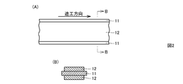
- partial top view (A) which shows the negative electrode material produced in the manufacturing process of Embodiment 1 of the nonaqueous electrolyte secondary battery of this invention, and sectional drawing (B) in the BB line of a partial top view (A) is there.
- partial plan view (A) which shows the positive electrode material produced in the manufacturing process of Embodiment 1 of the nonaqueous electrolyte secondary battery of this invention, and sectional drawing (B) in the BB line of a partial top view (A) is there.
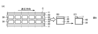
- Partial top view (A) which shows the cutting line of the composite of the negative electrode material, the separator, and the electrical insulation layer produced in the manufacturing process of Embodiment 1 of the nonaqueous electrolyte secondary battery of the present invention, and the negative electrode member after cutting It is a top view (B) (C) which shows two forms of the composite_body
- Partial plan view (A) which shows the cutting line of the positive electrode material produced in the manufacturing process of Embodiment 1 of the nonaqueous electrolyte secondary battery of this invention, and top view (B) which shows two forms of the positive electrode member after a cutting
- FIG. 6 It is a top view (A) (B) which shows two forms of the laminated body of the composite_body
- FIG. 6 shows two forms of the laminated body of the composite_body
- Embodiment 2 of the nonaqueous electrolyte secondary battery as an electrical storage device of this invention.
- the partial plan view (A) which shows the negative electrode material produced in the manufacturing process of Embodiment 2 of the nonaqueous electrolyte secondary battery of this invention
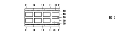
- FIG. 13 It is a top view which shows the cutting location of the composite_body
- FIG. 15A is a plan view showing a composite of a negative electrode material, a separator and an electrical insulating layer obtained by cutting different from FIG. 15,
- FIG. 16B is a plan view showing a positive electrode material obtained by cutting different from FIG. It is a top view (C) which shows a cutting line in the laminated body of this composite_body
- Embodiment 1 The basic structure of Embodiment 1 of the nonaqueous electrolyte secondary battery as the electricity storage device of the present invention will be described.
- the electrode structure 100 of a nonaqueous electrolyte secondary battery includes a positive electrode member 20, a negative electrode member 10, and a separator 30 interposed between the positive electrode member 20 and the negative electrode member 10.
- the positive electrode active material layer 22 is fixed to both surfaces of the positive electrode current collector 21.
- negative electrode active material layers 12 are fixed to both surfaces of the negative electrode current collector 11.
- the separator 30 is interposed between the positive electrode active material layer 22 and the negative electrode active material layer 12 and is permeable to the non-aqueous electrolyte.
- the separator 30 is formed of a material including at least an aggregate layer of electrically insulating substance particles in which electrically insulating substance particles are bonded together with a binder.
- the separator 30 is disposed so that the electrical insulating layer 40 faces at least a part of the peripheral side end face of the positive electrode active material layer 22 and is separated from at least a part of the peripheral side end face of the positive electrode active material layer 22. It is fixed on the surface.
- the electrode structure 100 configured as described above is accommodated in a container made of an outer packaging member such as a laminate film.
- the electrical insulating layer 40 is formed in an annular shape, and is disposed at a position surrounding the peripheral side end surface of the positive electrode active material layer 22 and spaced from the peripheral side end surface of the positive electrode active material layer 22. .
- the fixing form of the separator 30 is not limited, in the first embodiment, the separator 30 is fixed to the surface of the negative electrode active material layer 12.
- the positive electrode current collector 21 has a smaller planar area than the negative electrode current collector 11.
- the positive electrode active material layer 22 only needs to be fixed to at least one surface of the positive electrode current collector 21, and the negative electrode active material layer 12 only needs to be fixed to at least one surface of the negative electrode current collector 11.
- Embodiment 1 although the electrode structure 100 which consists of the laminated body of the positive electrode member 20, the separator 30, and the negative electrode member 10 was shown as basic structure, the some positive electrode member 20 and the some negative electrode member 10 are interposed via the separator 30.
- the present invention can also be applied to a laminate in which are alternately laminated.
- the electrical insulating layer 40 becomes the positive electrode active material. It contacts at least a part of the peripheral end surface of the layer 22 and serves as a stopper for the movement of the positive electrode member 20. For this reason, it can prevent that a part of positive electrode moves to the position which does not oppose a negative electrode. In other words, it is possible to prevent the displacement of the positive electrode member 20 during the manufacture of the nonaqueous electrolyte secondary battery.
- the annular electrical insulating layer 40 surrounds the peripheral side end face of the positive electrode active material layer 22, in the manufacturing process of the nonaqueous electrolyte secondary battery, the positive electrode member 20, the separator 30, and the negative electrode member 10 are used.
- the electrical insulating layer 40 comes into contact with the peripheral end surface of the positive electrode active material layer 22 and acts as a stopper for the movement of the positive electrode member 20. For this reason, it can prevent more reliably that a part of positive electrode moves to the position which does not oppose a negative electrode. That is, it is possible to more reliably prevent the displacement of the positive electrode member 20 during the manufacture of the nonaqueous electrolyte secondary battery.
- the first embodiment it is possible to prevent the circumferential end face of the positive electrode current collector 21 from coming into contact with the negative electrode current collector 11 by the annular electric insulating layer 40 fixed to the surface of the separator 30. As a result, an internal short circuit can be prevented.
- the thickness of the electrical insulating layer 40 is preferably equal to or less than the thickness of the positive electrode active material layer 22.
- the thickness of the separator 30 is preferably 0.1 ⁇ m or more and 30 ⁇ m or less, and the thickness of the electrical insulating layer 40 is preferably 0.1 ⁇ m or more and 30 ⁇ m or less.
- the electric insulating layer 40 may be made of an electric insulating material different from that of the separator 30, but is preferably made of the same electric insulating material as that of the separator 30.
- an electrically insulating material such as an inorganic material such as silica or alumina, or a mixture thereof can be used.
- an organic insulating material such as polyvinylidene fluoride, organic materials such as olefins such as polyethylene and polypropylene, inorganic materials such as silica and alumina, or a mixture thereof can be used.
- the separator 30 and the electrical insulating layer 40 are formed by applying and drying a material containing particles of the electrical insulating material and a binder.
- the positive electrode current collector 21 and the negative electrode current collector 11 aluminum or copper can be used as a material of the positive electrode current collector 21 and the negative electrode current collector 11.
- aluminum or copper can be used as a material of the positive electrode current collector 21 and the negative electrode current collector 11.
- an aluminum foil is used for the positive electrode current collector 21, and a copper foil is used for the negative electrode current collector 11. Is preferred.
- the separator 30 is fixed to the surface of the negative electrode active material layer 12, it is possible to more reliably prevent the displacement of the positive electrode member 20 with respect to the negative electrode member 10 during the manufacture of the nonaqueous electrolyte secondary battery.
- the electrode structure 100 is generally manufactured as follows. First, the positive electrode member 20 is produced by fixing the positive electrode active material layer 22 to at least one surface of the positive electrode current collector 21. On the other hand, the negative electrode active material layer 12 is fixed to at least one surface of the negative electrode current collector 11 to produce the negative electrode member 10. Next, a separator 30 including an aggregate layer of electrically insulating material particles is fixed to the surface of the negative electrode active material layer 12 of the negative electrode member 10. Then, the electrical insulating layer 40 is fixed to a part of the surface of the separator 30.
- the electrical insulating layer 40 is disposed so as to face at least a part of the peripheral end face of the positive electrode active material layer 22 and be separated from at least a part of the peripheral end face of the positive electrode active material layer 22.
- the positive electrode member 20 is disposed on the surface of the separator 30.
- Embodiment 1 comprising a laminate in which a plurality of positive electrode members 20 and a plurality of negative electrode members 10 are alternately laminated with separators 30 interposed therebetween will be described. This will be described below.
- the negative electrode active material is applied in the direction indicated by the arrow on both sides of the central region in the width direction, which is a partial surface of the strip-shaped negative electrode current collector 11 made of copper foil, and dried. By doing so, the negative electrode active material layer 12 is fixed. In this way, a negative electrode material is produced.
- a positive electrode active material is applied in a direction indicated by an arrow on both sides of a central region in the width direction, which is a partial surface of a strip-shaped positive electrode current collector 21 made of aluminum foil, and dried. By doing so, the positive electrode active material layer 22 is fixed. In this way, a positive electrode material is produced.
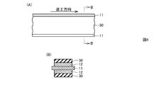
- a grid-like electric insulating layer 40 is fixed by applying a material containing electric insulating substance particles and a binder on the surface of the separator 30 and drying it. .
- a composite of the negative electrode material, the separator 30 and the electrical insulating layer 40 is produced.
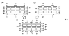
- the composite of the negative electrode material obtained above, the separator 30 and the electrical insulating layer 40 is cut according to the cutting line C as shown in FIG. Then, a composite of the negative electrode member for the double-sided lead tab, the separator 30 and the electrical insulating layer 40, which is used in a form in which the positive electrode and negative electrode lead tabs are disposed on both sides of the electrode structure, respectively. Further, by cutting a part of the negative electrode current collector 11, as shown in FIG. 6C, the negative electrode for the one-side lead tab used in the form in which the positive and negative lead tabs are arranged on one side of the electrode structure. A composite of the member, the separator 30 and the electrical insulating layer 40 can be produced.
- the positive electrode material obtained above is cut according to the cutting line C as shown in FIG. 7 (A), so that a positive electrode and a negative electrode are formed on both sides of the electrode structure as shown in FIG. 7 (B).
- the positive electrode member for both-side lead tabs used in the form in which the lead tabs are arranged is prepared. Further, by cutting a part of the positive electrode current collector 21, as shown in FIG. 7C, the positive electrode for the one-side lead tab used in the form in which the positive and negative lead tabs are arranged on one side of the electrode structure. A member can be produced.
- an electrode structure 200 composed of a laminate of the positive electrode member 20, the separator 30 and the negative electrode member 10 as shown in FIGS. make it.
- FIG. 8A shows an electrode structure for both-side lead tabs
- FIG. 8B shows an electrode structure for one-side lead tabs.
- the negative electrode lead tab 13 and the positive electrode lead tab are respectively shown in FIG. 23 is attached.
- FIG. 9 a laminated body of the separator 30, the negative electrode member 10, the separator 30, the positive electrode member 20, the separator 30, the positive electrode member 10, and the separator 30 is shown as a part of the laminated body constituting the electrode structure.
- Protective layers 50 made of aluminum foil are disposed on the outermost layers on both sides of the laminate.
- the protective layer 50 serves to protect the electrical insulating layer 40 disposed around the protective layer 50.
- the electrical insulating layer 40 protrudes outward, so that there is a problem that the electrical insulating layer 40 is easily damaged when contacting the inner wall surface of an outer packaging member such as a laminate film. Therefore, the above problem can be solved by disposing the protective layer 50.
- a material of the protective layer 50 a copper foil may be used.
- Embodiment 2 The basic structure of Embodiment 2 of the nonaqueous electrolyte secondary battery as the electricity storage device of the present invention will be described.
- the electrode structure 300 of the nonaqueous electrolyte secondary battery includes a positive electrode member 20, a negative electrode member 10, and a separator 30 interposed between the positive electrode member 20 and the negative electrode member 10.
- the second embodiment has the same structure as that of the first embodiment except that the positive electrode current collector 21 has substantially the same plane area as the negative electrode current collector 11. Since the positive electrode current collector 21 has substantially the same plane area as the negative electrode current collector 11, the productivity of the nonaqueous electrolyte secondary battery can be improved. Also in the second embodiment, it is possible to obtain the same effect as that of the first embodiment described above.
- the general manufacturing method of the electrode structure 300 is the same as the manufacturing method of the electrode structure 100 described above.
- the electrode structure according to the second embodiment which includes a laminate in which a plurality of positive electrode members 20 and a plurality of negative electrode members 10 are alternately laminated with separators 30 interposed therebetween, will be described. This will be described below.
- a negative electrode active material is applied in the direction indicated by the arrow on both sides of a central region in the width direction, which is a partial surface of a strip-shaped negative electrode current collector 11 made of copper foil, and dried. By doing so, the negative electrode active material layer 12 is fixed. In this way, a negative electrode material is produced.
- a positive electrode active material having a plurality of island-like patterns in the direction indicated by arrows on both surfaces of a central region in the width direction, which is a partial surface of a strip-shaped positive electrode current collector 21 made of aluminum foil. Is applied and dried to fix the positive electrode active material layer 22. In this way, a positive electrode material is produced.
- the composite of the negative electrode material obtained above, the separator 30 and the electrical insulating layer 40 is cut according to the cutting line C as shown in FIG. By this cutting, a composite of the negative electrode material, the separator 30 and the electrical insulating layer 40 is obtained in the shape shown in FIG. Furthermore, the composite body having the shape shown in FIG. 17A is obtained by cutting the portion C shown in FIG.
- the positive electrode material obtained above is cut according to the cutting line C as shown in FIG. By this cutting, a positive electrode material having the shape shown in FIG. 16 is obtained. Furthermore, the positive electrode material having the shape shown in FIG. 17B is obtained by cutting the portion C shown in FIG.
- an electrode structure material composed of a laminate of the positive electrode material, the separator 30 and the negative electrode material is produced as shown in FIG. .
- the electrode structure material is cut according to the cutting line C as shown in FIG.
- an electrode structure 400 composed of a laminate of the positive electrode member 20, the separator 30 and the negative electrode member 10 is produced.
- the electrode structure for one side lead tabs to which the negative electrode lead tab 13 and the positive electrode lead tab 23 were attached can be obtained.
- protective layers 50 made of aluminum foil are disposed on the outermost layers on both sides of the laminate.
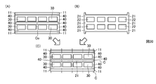
- the composite of the shape shown in FIGS. 17A and 17B is not cut and the positive electrode material, but the composite of the shape shown in FIG. 20A and the positive electrode of the shape shown in FIG. Materials can also be obtained.
- the portion C 0 in the central region of the complex is cut out.
- an electrode structure material composed of a laminate of the positive electrode material, the separator 30 and the negative electrode material is produced as shown in FIG. .
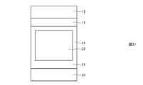
- the electrode structural material is cut according to the cutting line C as shown in FIG. Thereby, as shown in FIG. 21, an electrode structure composed of a laminate of the positive electrode member 20, the separator 30, and the negative electrode member 10 is produced.
- the electrode structure for both-sides lead tabs to which the negative electrode lead tab 13 and the positive electrode lead tab 23 were attached can be obtained.
- the positive electrode member 20 is formed by forming the positive electrode active material layer 22 containing the positive electrode active material on both surfaces of the positive electrode current collector 21 except for the end of the positive electrode current collector 21. Composed.
- the negative electrode member 10 is configured by forming negative electrode active material layers 12 including a negative electrode active material on both surfaces of the negative electrode current collector 11 except for an end portion of the negative electrode current collector 11.
- the positive electrode member 20 includes a positive electrode mixture slurry obtained by kneading a positive electrode active material, a binder, and, if necessary, a conductive agent in an organic solvent, on both surfaces of the positive electrode current collector 21 made of aluminum foil.
- the positive electrode active material layer 22 is formed on both surfaces of the positive electrode current collector 21 by being uniformly coated and dried.
- the positive electrode active materials include lithium cobalt oxide composite oxide, lithium manganate composite oxide, lithium nickelate composite oxide, lithium-nickel-manganese-cobalt composite oxide, lithium -Manganese-nickel composite oxide, lithium-manganese-cobalt composite oxide, lithium-nickel-cobalt composite oxide, and the like can be used.
- the positive electrode active material may be a mixture of the above materials.
- LiM x O 2 in the chemical formula, M represents one or more transition metals, x represents a charge / discharge state of the battery, and is usually 0.05 or more as a positive electrode active material of a non-aqueous electrolyte secondary battery.
- lithium composite oxide mainly composed of 1.10 or less.
- transition metal M Co, Ni, Mn and the like are preferable.
- These lithium composite oxides can generate a high voltage and become a positive electrode active material having an excellent energy density.
- the positive electrode active material may be a lithium-containing phosphate compound having an olivine type structure such as lithium iron phosphate represented by LiFePO 4 . If it has an olivine type structure, in the lithium iron phosphate represented by LiFePO 4 , a part of Fe is replaced with Al, Ti, V, Cr, Mn, Co, Ni, Zr, Nb, etc. Also good. A part of P may be replaced with B, Si, or the like.
- binder contained in the positive electrode mixture a known binder that is usually used in a positive electrode mixture of a nonaqueous electrolyte secondary battery can be used.
- a known additive such as a conductive agent and an oxide can be added to.
- Carbon materials such as furnace black and acetylene black are used as the conductive agent contained in the positive electrode mixture.
- a binder for binding the positive electrode active material and the conductive agent polyvinylidene fluoride (PVDF), polyamideimide (PAI), polyacrylonitrile (PAN), polyethylene (PE), polypropylene (PP), polytetrafluoro Ethylene (PTFE) or fluorine-based latex is used.
- a negative electrode slurry obtained by kneading a negative electrode active material, a binder, and, if necessary, a conductive agent in an organic solvent is uniformly formed on both surfaces of the negative electrode current collector 11 made of copper foil.
- the negative electrode active material layer 12 is formed on both surfaces of the negative electrode current collector 11 by coating and drying.
- carbon materials such as non-graphitizable carbon materials, graphitizable carbon materials (soft carbon), and graphite-based carbon materials can be used as the negative electrode active material.
- carbon materials such as pyrolytic carbons, cokes, graphites, glassy carbon fibers, organic polymer compound fired bodies, carbon fibers, and activated carbon can be used.
- the cokes include pitch coke, needle coke, and petroleum coke.
- said organic polymer compound fired body means what carbonized by baking a phenol resin, furan resin, etc. at a suitable temperature.
- materials that can be doped or dedoped with lithium include polymers such as polyacetylene and polypyrrole, Sn oxides such as SnO 2 , Sn alloys such as Sn 5 Cu 6 , and SiMg 2.
- An oxide such as an alloy or Li 4 Ti 5 O 12 (lithium titanate) can also be used.
- a binder contained in said negative electrode compound material the well-known binder used normally for the negative electrode compound material of a nonaqueous electrolyte secondary battery can be used, Said negative electrode compound material A known additive such as a conductive agent and an oxide can be added to.
- a known additive such as a conductive agent and an oxide can be added to.
- the binder for binding the negative electrode active material polyvinylidene fluoride, polyacrylonitrile, polyamideimide, polyacrylonitrile, polyethylene, polypropylene or polytetrafluoroethylene is used, or a latex binder such as styrene butadiene rubber and the like. A mixture of thickeners such as carboxymethylcellulose is used.
- the nonaqueous electrolytic solution is prepared by dissolving the supporting electrolyte in a nonaqueous solvent.
- a nonaqueous electrolyte for example, a solution obtained by dissolving LiPF 6 in a non-aqueous solvent at a concentration of 1.0 mol / L is used.
- supporting electrolytes other than LiPF 6 include lithium salts such as LiBF 4 , LiAsF 6 , LiClO 4 , LiCF 3 SO 3 , LiN (SO 2 CF 3 ) 2 , LiC (SO 2 CF 3 ) 3 , LiAlCl 4 , and LiSiF 6. Can be mentioned.
- LiPF 6 and LiBF 4 are particularly preferably used as the supporting electrolyte from the viewpoint of oxidation stability.
- a supporting electrolyte is preferably used by being dissolved in a nonaqueous solvent at a concentration of 0.1 mol / L to 3.0 mol / L, and at a concentration of 0.5 mol / L to 2.0 mol / L. More preferably, it is used after being dissolved.
- the non-aqueous solvent include cyclic carbonates such as ethylene carbonate (EC) and propylene carbonate (PC), dimethyl carbonate (DMC), ethyl methyl carbonate (EMC), and diethyl carbonate (DEC), which are low viscosity solvents. And a lower chain carbonate of the above are used.
- the present invention is applied to a non-aqueous electrolyte secondary battery as an example of an electricity storage device, but a container of an outer packaging member such as a laminate film is used to accommodate at least an electrode structure.
- the present invention can be applied to any power storage device.
- the present invention can be applied to an electric double layer capacitor in addition to a non-aqueous electrolyte secondary battery.
- the outer packaging member is not limited to a flexible member made of a laminate film having a three-layer structure.
- the present invention it is possible to prevent the displacement of the positive electrode during the manufacture of the electricity storage device, so the present invention improves the reliability of electricity storage devices such as non-aqueous electrolyte secondary batteries and electric double layer capacitors. Can contribute.
Landscapes
- Engineering & Computer Science (AREA)
- Power Engineering (AREA)
- Chemical & Material Sciences (AREA)
- Chemical Kinetics & Catalysis (AREA)
- Electrochemistry (AREA)
- General Chemical & Material Sciences (AREA)
- Microelectronics & Electronic Packaging (AREA)
- Manufacturing & Machinery (AREA)
- Secondary Cells (AREA)
- Battery Electrode And Active Subsutance (AREA)
- Electric Double-Layer Capacitors Or The Like (AREA)
- Cell Separators (AREA)
Abstract
L'invention concerne : un dispositif de stockage d'électricité dont un décalage de position d'une électrode positive durant la fabrication du dispositif de stockage d'électricité peut être évité ; et un procédé de fabrication du dispositif de stockage d'électricité. Une structure d'électrode (100) d'une batterie secondaire à électrolyte non aqueux est configurée : d'un élément d'électrode positive (20) dans lequel une couche de matériau actif d'électrode positive (22) est collée fermement sur au moins une surface d'un collecteur d'électrode positive (21) ; d'un élément d'électrode négative (10) dans lequel une couche de matériau actif d'électrode négative (12) est collée fermement sur au moins une surface d'un collecteur d'électrode négative (11) de façon à faire face à la couche de matériau actif d'électrode positive (22) ; d'un séparateur (30) qui est interposé entre la couche de matériau actif d'électrode positive (22) et la couche de matériau actif d'électrode négative (12) et qui contient une couche d'un agrégat de particules de matériau électriquement isolant ; et d'une couche électriquement isolante (40) qui est collée fermement sur la surface du séparateur (30) de façon à faire face à au moins une partie de la surface de bord latéral périphérique de la couche de matériau actif d'électrode positive (22) et de façon à être positionnée à une distance d'au moins une partie de la surface de bord latéral périphérique de la couche de matériau actif d'électrode positive (22).
Priority Applications (1)
| Application Number | Priority Date | Filing Date | Title |
|---|---|---|---|
| JP2014551964A JP6149867B2 (ja) | 2012-12-11 | 2013-11-27 | 蓄電デバイスの製造方法 |
Applications Claiming Priority (2)
| Application Number | Priority Date | Filing Date | Title |
|---|---|---|---|
| JP2012-270659 | 2012-12-11 | ||
| JP2012270659 | 2012-12-11 |
Publications (1)
| Publication Number | Publication Date |
|---|---|
| WO2014091925A1 true WO2014091925A1 (fr) | 2014-06-19 |
Family
ID=50934219
Family Applications (1)
| Application Number | Title | Priority Date | Filing Date |
|---|---|---|---|
| PCT/JP2013/081847 Ceased WO2014091925A1 (fr) | 2012-12-11 | 2013-11-27 | Dispositif de stockage d'électricité et procédé de fabrication associé |
Country Status (2)
| Country | Link |
|---|---|
| JP (1) | JP6149867B2 (fr) |
| WO (1) | WO2014091925A1 (fr) |
Cited By (3)
| Publication number | Priority date | Publication date | Assignee | Title |
|---|---|---|---|---|
| CN112993378A (zh) * | 2021-03-26 | 2021-06-18 | 天津市捷威动力工业有限公司 | 一种应用于锂二次电池的电极组件 |
| JPWO2021131095A1 (fr) * | 2019-12-27 | 2021-07-01 | ||
| JP2025008515A (ja) * | 2023-07-05 | 2025-01-20 | トヨタ自動車株式会社 | 蓄電セル及び電極体の製造方法 |
Citations (6)
| Publication number | Priority date | Publication date | Assignee | Title |
|---|---|---|---|---|
| JP2001102050A (ja) * | 1999-09-30 | 2001-04-13 | Toyota Motor Corp | 積層型電池・キャパシタ用電極構造体 |
| JP2005190912A (ja) * | 2003-12-26 | 2005-07-14 | Matsushita Electric Ind Co Ltd | リチウム二次電池およびその製造方法 |
| JP2012009210A (ja) * | 2010-06-23 | 2012-01-12 | Mitsubishi Heavy Ind Ltd | 電池 |
| JP2012069283A (ja) * | 2010-09-21 | 2012-04-05 | Nissan Motor Co Ltd | 積層型電池の製造方法および積層型電池用セパレータ |
| JP2012190696A (ja) * | 2011-03-11 | 2012-10-04 | Mitsubishi Heavy Ind Ltd | 電池 |
| JP2012209072A (ja) * | 2011-03-29 | 2012-10-25 | Nec Corp | 電極積層型電池の電極積層体、および該電極積層体の製造方法 |
Family Cites Families (2)
| Publication number | Priority date | Publication date | Assignee | Title |
|---|---|---|---|---|
| JP4003845B2 (ja) * | 1997-04-17 | 2007-11-07 | 日立マクセル株式会社 | 電気二重層キャパシタと電池とのハイブリッド素子 |
| US6277520B1 (en) * | 1999-03-19 | 2001-08-21 | Ntk Powerdex, Inc. | Thin lithium battery with slurry cathode |
-
2013
- 2013-11-27 WO PCT/JP2013/081847 patent/WO2014091925A1/fr not_active Ceased
- 2013-11-27 JP JP2014551964A patent/JP6149867B2/ja active Active
Patent Citations (6)
| Publication number | Priority date | Publication date | Assignee | Title |
|---|---|---|---|---|
| JP2001102050A (ja) * | 1999-09-30 | 2001-04-13 | Toyota Motor Corp | 積層型電池・キャパシタ用電極構造体 |
| JP2005190912A (ja) * | 2003-12-26 | 2005-07-14 | Matsushita Electric Ind Co Ltd | リチウム二次電池およびその製造方法 |
| JP2012009210A (ja) * | 2010-06-23 | 2012-01-12 | Mitsubishi Heavy Ind Ltd | 電池 |
| JP2012069283A (ja) * | 2010-09-21 | 2012-04-05 | Nissan Motor Co Ltd | 積層型電池の製造方法および積層型電池用セパレータ |
| JP2012190696A (ja) * | 2011-03-11 | 2012-10-04 | Mitsubishi Heavy Ind Ltd | 電池 |
| JP2012209072A (ja) * | 2011-03-29 | 2012-10-25 | Nec Corp | 電極積層型電池の電極積層体、および該電極積層体の製造方法 |
Cited By (4)
| Publication number | Priority date | Publication date | Assignee | Title |
|---|---|---|---|---|
| JPWO2021131095A1 (fr) * | 2019-12-27 | 2021-07-01 | ||
| JP7565525B2 (ja) | 2019-12-27 | 2024-10-11 | パナソニックIpマネジメント株式会社 | 電池の製造方法 |
| CN112993378A (zh) * | 2021-03-26 | 2021-06-18 | 天津市捷威动力工业有限公司 | 一种应用于锂二次电池的电极组件 |
| JP2025008515A (ja) * | 2023-07-05 | 2025-01-20 | トヨタ自動車株式会社 | 蓄電セル及び電極体の製造方法 |
Also Published As
| Publication number | Publication date |
|---|---|
| JP6149867B2 (ja) | 2017-06-21 |
| JPWO2014091925A1 (ja) | 2017-01-05 |
Similar Documents
| Publication | Publication Date | Title |
|---|---|---|
| KR101304108B1 (ko) | 각형 전지 | |
| US10270121B2 (en) | Secondary battery | |
| JP5554181B2 (ja) | 非水電解質二次電池 | |
| JP6936670B2 (ja) | リチウムイオン電池用セパレータ | |
| JP7405243B2 (ja) | 集電体、蓄電素子及び蓄電モジュール | |
| WO2018154989A1 (fr) | Pile rechargeable et son procédé de fabrication | |
| WO2017110684A1 (fr) | Pile rechargeable et son procédé de fabrication | |
| JP2009187675A (ja) | 積層型二次電池およびその製造方法 | |
| JP5625279B2 (ja) | 積層型二次電池用極板の製造方法と積層型二次電池用極板材料 | |
| WO2013002058A1 (fr) | Dispositif de stockage électrique | |
| JP6149867B2 (ja) | 蓄電デバイスの製造方法 | |
| JP5755870B2 (ja) | 二次電池用正極電極、二次電池、および二次電池用正極電極の製造方法 | |
| WO2019093226A1 (fr) | Batterie secondaire au lithium-ion | |
| US20200295397A1 (en) | Lithium secondary battery | |
| JP2018174032A (ja) | 非水電解液二次電池 | |
| JP7332034B2 (ja) | 電極体、蓄電素子および蓄電モジュール | |
| JP2012195122A (ja) | 非水電解液二次電池 | |
| KR20230087039A (ko) | 리튬 이차 전지 | |
| JP7400946B2 (ja) | 電極体、蓄電素子および蓄電モジュール | |
| KR102813081B1 (ko) | 전극 및 이를 포함하는 리튬 이차전지 | |
| JP7670081B2 (ja) | 積層電池 | |
| JP2006147185A (ja) | 捲回電極およびその製造方法、並びにそれを用いた電池 | |
| EP4557419A1 (fr) | Batterie secondaire | |
| WO2018154987A1 (fr) | Batterie rechargeable et procédé permettant de produire cette dernière | |
| JP2019029183A (ja) | セパレータ付き二次電池用電極、二次電池、それらの製造方法 |
Legal Events
| Date | Code | Title | Description |
|---|---|---|---|
| 121 | Ep: the epo has been informed by wipo that ep was designated in this application |
Ref document number: 13862675 Country of ref document: EP Kind code of ref document: A1 |
|
| ENP | Entry into the national phase |
Ref document number: 2014551964 Country of ref document: JP Kind code of ref document: A |
|
| NENP | Non-entry into the national phase |
Ref country code: DE |
|
| 122 | Ep: pct application non-entry in european phase |
Ref document number: 13862675 Country of ref document: EP Kind code of ref document: A1 |