WO2014091992A1 - 眼科装置 - Google Patents
眼科装置 Download PDFInfo
- Publication number
- WO2014091992A1 WO2014091992A1 PCT/JP2013/082641 JP2013082641W WO2014091992A1 WO 2014091992 A1 WO2014091992 A1 WO 2014091992A1 JP 2013082641 W JP2013082641 W JP 2013082641W WO 2014091992 A1 WO2014091992 A1 WO 2014091992A1
- Authority
- WO
- WIPO (PCT)
- Prior art keywords
- optical system
- eye
- unit
- alignment
- examined
- Prior art date
- Legal status (The legal status is an assumption and is not a legal conclusion. Google has not performed a legal analysis and makes no representation as to the accuracy of the status listed.)
- Ceased
Links
Images


Classifications
-
- A—HUMAN NECESSITIES
- A61—MEDICAL OR VETERINARY SCIENCE; HYGIENE
- A61B—DIAGNOSIS; SURGERY; IDENTIFICATION
- A61B3/00—Apparatus for testing the eyes; Instruments for examining the eyes
- A61B3/10—Objective types, i.e. instruments for examining the eyes independent of the patients' perceptions or reactions
- A61B3/14—Arrangements specially adapted for eye photography
- A61B3/15—Arrangements specially adapted for eye photography with means for aligning, spacing or blocking spurious reflection ; with means for relaxing
- A61B3/152—Arrangements specially adapted for eye photography with means for aligning, spacing or blocking spurious reflection ; with means for relaxing for aligning
-
- A—HUMAN NECESSITIES
- A61—MEDICAL OR VETERINARY SCIENCE; HYGIENE
- A61B—DIAGNOSIS; SURGERY; IDENTIFICATION
- A61B3/00—Apparatus for testing the eyes; Instruments for examining the eyes
- A61B3/0016—Operational features thereof
- A61B3/0025—Operational features thereof characterised by electronic signal processing, e.g. eye models
-
- A—HUMAN NECESSITIES
- A61—MEDICAL OR VETERINARY SCIENCE; HYGIENE
- A61B—DIAGNOSIS; SURGERY; IDENTIFICATION
- A61B3/00—Apparatus for testing the eyes; Instruments for examining the eyes
- A61B3/0083—Apparatus for testing the eyes; Instruments for examining the eyes provided with means for patient positioning
-
- A—HUMAN NECESSITIES
- A61—MEDICAL OR VETERINARY SCIENCE; HYGIENE
- A61B—DIAGNOSIS; SURGERY; IDENTIFICATION
- A61B3/00—Apparatus for testing the eyes; Instruments for examining the eyes
- A61B3/10—Objective types, i.e. instruments for examining the eyes independent of the patients' perceptions or reactions
- A61B3/113—Objective types, i.e. instruments for examining the eyes independent of the patients' perceptions or reactions for determining or recording eye movement
-
- A—HUMAN NECESSITIES
- A61—MEDICAL OR VETERINARY SCIENCE; HYGIENE
- A61B—DIAGNOSIS; SURGERY; IDENTIFICATION
- A61B3/00—Apparatus for testing the eyes; Instruments for examining the eyes
- A61B3/10—Objective types, i.e. instruments for examining the eyes independent of the patients' perceptions or reactions
- A61B3/14—Arrangements specially adapted for eye photography
- A61B3/15—Arrangements specially adapted for eye photography with means for aligning, spacing or blocking spurious reflection ; with means for relaxing
-
- A—HUMAN NECESSITIES
- A61—MEDICAL OR VETERINARY SCIENCE; HYGIENE
- A61B—DIAGNOSIS; SURGERY; IDENTIFICATION
- A61B3/00—Apparatus for testing the eyes; Instruments for examining the eyes
- A61B3/0091—Fixation targets for viewing direction
-
- A—HUMAN NECESSITIES
- A61—MEDICAL OR VETERINARY SCIENCE; HYGIENE
- A61B—DIAGNOSIS; SURGERY; IDENTIFICATION
- A61B3/00—Apparatus for testing the eyes; Instruments for examining the eyes
- A61B3/10—Objective types, i.e. instruments for examining the eyes independent of the patients' perceptions or reactions
- A61B3/102—Objective types, i.e. instruments for examining the eyes independent of the patients' perceptions or reactions for optical coherence tomography [OCT]
-
- A—HUMAN NECESSITIES
- A61—MEDICAL OR VETERINARY SCIENCE; HYGIENE
- A61B—DIAGNOSIS; SURGERY; IDENTIFICATION
- A61B3/00—Apparatus for testing the eyes; Instruments for examining the eyes
- A61B3/10—Objective types, i.e. instruments for examining the eyes independent of the patients' perceptions or reactions
- A61B3/11—Objective types, i.e. instruments for examining the eyes independent of the patients' perceptions or reactions for measuring interpupillary distance or diameter of pupils
- A61B3/112—Objective types, i.e. instruments for examining the eyes independent of the patients' perceptions or reactions for measuring interpupillary distance or diameter of pupils for measuring diameter of pupils
-
- A—HUMAN NECESSITIES
- A61—MEDICAL OR VETERINARY SCIENCE; HYGIENE
- A61B—DIAGNOSIS; SURGERY; IDENTIFICATION
- A61B3/00—Apparatus for testing the eyes; Instruments for examining the eyes
- A61B3/10—Objective types, i.e. instruments for examining the eyes independent of the patients' perceptions or reactions
- A61B3/117—Objective types, i.e. instruments for examining the eyes independent of the patients' perceptions or reactions for examining the anterior chamber or the anterior chamber angle, e.g. gonioscopes
-
- A—HUMAN NECESSITIES
- A61—MEDICAL OR VETERINARY SCIENCE; HYGIENE
- A61B—DIAGNOSIS; SURGERY; IDENTIFICATION
- A61B3/00—Apparatus for testing the eyes; Instruments for examining the eyes
- A61B3/10—Objective types, i.e. instruments for examining the eyes independent of the patients' perceptions or reactions
- A61B3/12—Objective types, i.e. instruments for examining the eyes independent of the patients' perceptions or reactions for looking at the eye fundus, e.g. ophthalmoscopes
- A61B3/1225—Objective types, i.e. instruments for examining the eyes independent of the patients' perceptions or reactions for looking at the eye fundus, e.g. ophthalmoscopes using coherent radiation
Definitions
- This invention relates to an ophthalmologic apparatus.
- the ophthalmologic apparatus includes an ophthalmologic photographing apparatus for obtaining an image of the eye to be examined and an ophthalmologic measuring apparatus for measuring the characteristics of the eye to be examined.
- an optical coherence tomography (Optical Coherence Tomography, OCT) is used to obtain a tomographic image, a fundus camera for photographing the fundus, and laser scanning using a confocal optical system.
- OCT optical Coherence Tomography
- ophthalmic measuring devices include an ocular refraction examination device (refractometer, keratometer) that measures the refractive characteristics of the eye to be examined, a tonometer, a specular microscope that obtains corneal properties (corneal thickness, cell distribution, etc.), Hartmann -There is a wavefront analyzer that obtains aberration information of the eye to be examined using a shack sensor.
- refractometer keratometer
- keratometer keratometer
- specular microscope that obtains corneal properties (corneal thickness, cell distribution, etc.)
- the alignment includes an operation for aligning the optical axis of the apparatus optical system with the axis of the eye to be examined (xy alignment) and an operation for adjusting the distance between the eye to be examined and the apparatus optical system (z alignment).
- JP 2009-112664 A Japanese Patent No. 4136690
- the examination may not be performed properly.
- the line of sight of the eye to be inspected is displaced as when photographing the periphery of the fundus, the fundus examination light beam is obstructed by the iris and data cannot be obtained, Sometimes mixed in.
- the miosis state and eyelid state of the eye to be examined may have an adverse effect on the examination.
- An object of the present invention is to provide an ophthalmologic apparatus capable of suitably performing an examination according to the state of an eye to be examined.
- an inspection optical system for inspecting the eye to be examined, a drive unit for moving the inspection optical system, and an anterior eye part of the eye to be examined are photographed substantially simultaneously from different directions.
- the invention according to claim 2 is the ophthalmologic apparatus according to claim 1, wherein the analysis unit analyzes the photographed image, and thereby the feature in the photographed image corresponding to the characteristic part of the anterior eye part.
- a feature region specifying unit that specifies a region, a shape information acquiring unit that acquires shape information of the feature region by analyzing the specified feature region, and a displacement that acquires the displacement information based on the acquired shape information And an information acquisition unit.
- the invention according to claim 3 is the ophthalmologic apparatus according to claim 2, wherein the feature region specifying unit specifies a pupil region corresponding to a pupil or an iris region corresponding to an iris as the feature region,
- the shape information acquisition unit calculates an approximate ellipse of the outline of the specified pupil region or iris region, calculates the shape information by calculating the major axis and the minor axis of the approximate ellipse, and the displacement information acquisition unit
- the displacement information is obtained by obtaining the displacement direction based on the direction of the major axis or the minor axis and obtaining the displacement amount based on the ratio of the major axis to the minor axis.
- a fourth aspect of the present invention is the ophthalmic apparatus according to any one of the first to third aspects, wherein the analysis unit is acquired substantially simultaneously by the two or more imaging units.
- the analysis unit is acquired substantially simultaneously by the two or more imaging units.
- a feature point identifying unit that identifies a position in the captured image corresponding to the feature point of the anterior segment, a position corresponding to the identified feature point, and the two or more captured images
- a three-dimensional position calculation unit that calculates a three-dimensional position of the feature point based on the position of the part, and the calculated three-dimensional position of the feature point is set as the three-dimensional position of the eye to be examined.
- the invention according to claim 5 is the ophthalmologic apparatus according to any one of claims 1 to 4, wherein the control unit performs the second alignment after executing the first alignment processing. A process is executed.
- the invention according to claim 6 is the ophthalmologic apparatus according to any one of claims 1 to 4, wherein an alignment index for performing alignment of the optical system for inspection with respect to the eye to be examined is an anterior segment.
- An alignment optical system that projects onto the eye, and a front image acquisition unit that acquires the front image of the anterior ocular segment by capturing the eye to be examined in a state where the alignment index is projected, and the analysis unit includes the front image To obtain a displacement of the inspection optical system with respect to the eye to be examined, and the control unit determines success or failure of the first alignment process.
- a seventh aspect of the present invention is the ophthalmic apparatus according to any one of the first to sixth aspects, wherein the control unit is configured to perform the inspection optical with respect to a displacement direction and a displacement amount of the eye to be examined.
- a first storage unit that stores first correspondence information associated with a movement direction and a movement amount of the system in advance, and a movement direction and a movement amount corresponding to the displacement direction and the displacement amount indicated in the displacement information acquired by the analysis unit; And a first movement information specifying unit that specifies the first correspondence information based on the first correspondence information, and performing the second alignment process based on the specified movement direction and movement amount.
- the invention according to claim 8 is the ophthalmologic apparatus according to claim 7, wherein the moving direction is a direction orthogonal to the optical axis of the inspection optical system.
- the invention according to claim 9 is the ophthalmologic apparatus according to claim 8, wherein the control unit controls the drive unit based on the amount of movement to move the inspection optical system in the direction of the optical axis.
- a third alignment process for moving is executed.
- a tenth aspect of the present invention is the ophthalmologic apparatus according to any one of the first to ninth aspects, wherein the displacement direction includes a rotation direction of the eye to be examined, and the amount of displacement is determined by the eye to be examined. The amount of rotation is included.
- an inspection optical system for inspecting the eye to be inspected, a drive unit for moving the inspection optical system, and a fixation optical for projecting a fixation target for gaze guidance onto the eye to be examined.
- the system two or more imaging units that image the anterior segment of the eye to be examined substantially simultaneously from different directions, and the three-dimensional position of the eye to be examined by analyzing the captured images acquired by the two or more imaging units
- An ophthalmologic apparatus comprising: a first alignment process; and a control unit that executes a second alignment process for moving the inspection optical system by controlling the drive unit based on a projection position of the fixation target.
- the invention according to claim 12 is the ophthalmologic apparatus according to claim 11, wherein the control unit associates the movement direction and the movement amount of the inspection optical system with the projection position of the fixation target.
- a second storage unit that stores the second correspondence information in advance, and a second movement information that specifies a movement direction and a movement amount corresponding to the projection position of the fixation target by the fixation optical system based on the second correspondence information. Including a specifying unit, and performing the second alignment process based on the specified moving direction and moving amount.
- the invention described in claim 13 is the ophthalmologic apparatus according to claim 12, wherein the fixation optical system includes a fixation target presenting unit capable of presenting the fixation target at a plurality of positions, and a fixed fixation presented.
- a fixation target projection optical system that projects a target on the eye to be examined, and the second correspondence information is associated with a movement direction and a movement amount for each of the plurality of positions, and the control unit Controls the fixation target presenting unit to present the fixation target at any of the plurality of positions, and the second movement information specifying unit is located at the position where the fixation target is presented by the control unit.
- a corresponding movement direction and movement amount are specified based on the second correspondence information.
- a fourteenth aspect of the invention is the ophthalmic apparatus according to the twelfth or thirteenth aspect of the invention, wherein the moving direction is a direction orthogonal to the optical axis of the inspection optical system.
- the invention according to claim 15 is the ophthalmologic apparatus according to claim 14, wherein the control unit controls the drive unit based on the amount of movement so that the inspection optical system is oriented in the direction of the optical axis.
- a third alignment process for moving is executed.
- the invention described in claim 16 is the ophthalmologic apparatus according to any one of claims 11 to 15, wherein the control unit performs the second alignment after executing the first alignment process. A process is executed.
- the invention according to claim 17 is the ophthalmologic apparatus according to any one of claims 11 to 15, wherein an alignment index for aligning the optical system for inspection with respect to the eye to be examined is an anterior segment.
- An alignment optical system that projects onto the lens and a front image acquisition unit that acquires the front image of the anterior ocular segment by photographing the eye to be examined while the alignment index is projected, and the analysis unit analyzes the front image
- the displacement of the inspection optical system with respect to the eye to be examined is acquired, and the control unit determines whether or not the first alignment process is successful.
- the second positioning process is executed after the drive unit is controlled based on the alignment.
- an optical system including an inspection optical system for inspecting an eye to be inspected, a drive unit that moves the inspection optical system, and an anterior eye part of the eye to be inspected substantially from different directions.
- the three-dimensional position of the eye to be examined and pupil information indicating the state of the pupil of the eye to be examined are acquired.
- an alignment unit that controls the driving unit based on the three-dimensional position to move the inspection optical system, and an optical system control process that controls the optical system based on the pupil information.
- An ophthalmologic apparatus having a control unit.
- the invention according to claim 19 is the ophthalmologic apparatus according to claim 18, wherein the optical system includes a fixation optical system that projects a fixation target for visual line guidance onto the eye to be examined, and the analysis unit includes The pupil size is acquired as the pupil information, and the control unit controls the fixation optical system based on the acquired pupil size and changes the intensity of the projected light flux of the fixation target as the optical system control process. It is characterized by doing.
- the invention according to claim 20 is the ophthalmic apparatus according to claim 18, wherein the optical system is arranged coaxially with the optical system for examination and irradiates continuous light to the eye to be examined.
- a first imaging optical system that is arranged coaxially with the examination optical system and that takes a moving image of the eye to be examined that is irradiated with the continuous light, and the analysis unit acquires a pupil size as the pupil information
- the control unit controls the first illumination optical system based on the acquired pupil size and changes the intensity of the continuous light as the optical system control process.
- the invention according to claim 21 is the ophthalmologic apparatus according to claim 18, wherein the optical system is arranged coaxially with the inspection optical system and irradiates flash light to the eye to be examined.
- a second imaging optical system that is arranged coaxially with the examination optical system and images the eye to be examined in synchronization with the irradiation of the flash light, and the analysis unit acquires a pupil size as the pupil information
- the controller controls the second illumination optical system based on the acquired pupil size and changes the intensity of the flash light as the optical system control process.
- the invention according to claim 22 is the ophthalmologic apparatus according to claim 18, wherein the optical system includes two or more stops arranged coaxially with the inspection optical system and having different aperture sizes, and the eye to be examined A third illumination optical system that irradiates the illumination light, and a third imaging optical system that is arranged coaxially with the inspection optical system and that images the eye to be inspected that is illuminated with the illumination light.
- the pupil size is acquired as the pupil information, and the control unit selectively arranges the two or more stops in the optical path of the third illumination optical system based on the acquired pupil size as the optical system control process. It is characterized by that.
- the invention according to claim 23 is the ophthalmologic apparatus according to claim 18, wherein the analysis unit acquires a pupil shape as the pupil information, and the control unit is acquired as the optical system control process.
- the inspection optical system is moved by controlling the driving unit based on the pupil shape.
- an inspection optical system for inspecting the eye to be inspected a drive unit for moving the inspection optical system, and an anterior eye part of the eye to be inspected are photographed substantially simultaneously from different directions Two or more imaging units, a process of acquiring a three-dimensional position of the eye to be examined by analyzing captured images acquired by the two or more imaging units, and a process of determining the presence or absence of blinking of the eye to be examined
- the ophthalmologic apparatus has an analysis unit that performs and a notification unit that notifies a determination result by the analysis unit.
- the invention according to claim 25 is the ophthalmologic apparatus according to claim 24, wherein the notification unit displays the display when it is determined by the display unit and the analysis unit that the eye to be examined is blinking. And a control unit that displays warning information on the unit. Note that the above-described inventions can be arbitrarily combined.
- the ophthalmologic apparatus according to the present invention is used for optical examination of an eye to be examined.
- an ophthalmologic apparatus includes an ophthalmologic photographing apparatus and an ophthalmologic measurement apparatus.
- the ophthalmologic photographing apparatus include an optical coherence tomometer, a fundus camera, and a scanning laser ophthalmoscope slit lamp.
- examples of the ophthalmologic measurement apparatus include an eye refraction inspection apparatus, a tonometer, a specular microscope, and a wave front analyzer.
- the present invention is applied to an optical coherence tomography will be described in detail, but the present invention can be applied to any other ophthalmologic apparatus.
- images acquired by OCT may be collectively referred to as OCT images.
- a measurement operation for forming an OCT image may be referred to as OCT measurement.
- an optical coherence tomography using a so-called Spectral Domain type OCT equipped with a low-coherence light source and a spectroscope will be described.
- types other than the spectral domain such as swept sources, are described.
- the present invention to an optical coherence tomography using a type or in-face type OCT technique.
- the swept source OCT is a scanning (wavelength sweep) of the wavelength of light irradiated on the object to be measured, and the interference light obtained by superimposing the reflected light of each wavelength and the reference light.
- in-face OCT is a method of irradiating a measured object with light having a predetermined beam diameter, and analyzing a component of interference light obtained by superimposing the reflected light and reference light.
- This is a technique for forming an image of an object to be measured in a cross section perpendicular to the traveling direction of light, and is also called a full-field type.
- an apparatus combining an OCT apparatus and a fundus camera will be described.
- the application target of the present invention is not limited to such a multifunction machine, and an ophthalmologic apparatus (for example, a fundus camera alone) as a single machine. It is also possible to apply this invention to
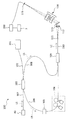
- the ophthalmologic apparatus 1 includes a fundus camera unit 2, an OCT unit 100, and an arithmetic control unit 200.
- the retinal camera unit 2 has almost the same optical system as a conventional retinal camera.
- the OCT unit 100 is provided with an optical system for acquiring an OCT image of the fundus.
- the arithmetic control unit 200 includes a computer that executes various arithmetic processes and control processes.
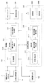
- the fundus camera unit 2 shown in FIG. 1 is provided with an optical system for obtaining a two-dimensional image (fundus image) representing the surface form of the fundus oculi Ef of the eye E to be examined.
- the fundus image includes an observation image and a captured image.
- the observation image is, for example, a monochrome moving image formed at a predetermined frame rate using near infrared light.
- the fundus camera unit 2 can obtain an observation image of the anterior segment Ea.
- the captured image may be, for example, a color image obtained by flashing visible light, or a monochrome still image using near infrared light or visible light as illumination light.
- the fundus camera unit 2 may be configured to be able to acquire images other than these, such as a fluorescein fluorescent image, an indocyanine green fluorescent image, a spontaneous fluorescent image, and the like.
- the fundus camera unit 2 is provided with a chin rest and a forehead for supporting the subject's face.
- the chin rest and the forehead support correspond to the support portion 440 shown in FIGS. 4A and 4B.
- reference numeral 410 denotes a drive system such as the optical system drive unit 2A and a base in which an arithmetic control circuit is stored.
- Reference numeral 420 denotes a housing provided on the base 410 and storing an optical system.
- Reference numeral 430 denotes a lens housing portion that is provided on the front surface of the housing 420 and accommodates the objective lens 22.
- the fundus camera unit 2 is provided with an illumination optical system 10 and a photographing optical system 30.
- the illumination optical system 10 irradiates the fundus oculi Ef with illumination light.
- the photographing optical system 30 guides the fundus reflection light of the illumination light to an imaging device (CCD image sensor (sometimes simply referred to as a CCD) 35, 38).
- the imaging optical system 30 guides the signal light from the OCT unit 100 to the fundus oculi Ef and guides the signal light passing through the fundus oculi Ef to the OCT unit 100.
- the observation light source 11 of the illumination optical system 10 is composed of, for example, a halogen lamp.
- the light (observation illumination light) output from the observation light source 11 is reflected by the reflection mirror 12 having a curved reflection surface, passes through the condensing lens 13, passes through the visible cut filter 14, and is converted into near infrared light. Become. Further, the observation illumination light is once converged in the vicinity of the photographing light source 15, reflected by the mirror 16, and passes through the relay lenses 17 and 18, the diaphragm 19 and the relay lens 20. Then, the observation illumination light is reflected at the peripheral portion (region around the hole portion) of the aperture mirror 21, passes through the dichroic mirror 46, and is refracted by the objective lens 22 to illuminate the fundus oculi Ef.
- An LED Light Emitting Diode
- the fundus reflection light of the observation illumination light is refracted by the objective lens 22, passes through the dichroic mirror 46, passes through the hole formed in the central region of the perforated mirror 21, passes through the dichroic mirror 55, and is a focusing lens. It is reflected by the mirror 32 via 31. Further, the fundus reflection light passes through the half mirror 39A, is reflected by the dichroic mirror 33, and forms an image on the light receiving surface of the CCD image sensor 35 by the condenser lens.
- the CCD image sensor 35 detects fundus reflected light at a predetermined frame rate, for example.
- On the display device 3 an image (observation image) based on fundus reflection light detected by the CCD image sensor 35 is displayed.
- an observation image is an example of a front image obtained by photographing the anterior segment Ea from the front of the subject.
- the photographing light source 15 is constituted by, for example, a xenon lamp.
- the light (imaging illumination light) output from the imaging light source 15 is applied to the fundus oculi Ef through the same path as the observation illumination light.
- the fundus reflection light of the imaging illumination light is guided to the dichroic mirror 33 through the same path as that of the observation illumination light, passes through the dichroic mirror 33, is reflected by the mirror 36, and is reflected by the condenser lens 37 of the CCD image sensor 38.
- An image is formed on the light receiving surface.
- On the display device 3 an image (captured image) based on fundus reflection light detected by the CCD image sensor 38 is displayed.
- the display device 3 that displays the observation image and the display device 3 that displays the captured image may be the same or different.
- an infrared captured image is displayed. It is also possible to use an LED as a photographing light source.
- the photographed image is an example of a front image obtained by photographing the anterior segment Ea from the front of the subject.
- the LCD (Liquid Crystal Display) 39 displays a fixation target and an eyesight measurement index.
- the fixation target is an index for fixing the eye E to be examined, and is used at the time of fundus photographing or OCT measurement.
- a part of the light output from the LCD 39 is reflected by the half mirror 39A, reflected by the mirror 32, passes through the focusing lens 31 and the dichroic mirror 55, passes through the hole of the perforated mirror 21, and reaches the dichroic.
- the light passes through the mirror 46, is refracted by the objective lens 22, and is projected onto the fundus oculi Ef.
- the projection direction of the fixation target with respect to the eye E that is, the fixation position of the eye E can be changed.
- the fixation position of the eye E for example, a position for acquiring an image centered on the macular portion of the fundus oculi Ef, or a position for acquiring an image centered on the optic disc as in the case of a conventional fundus camera And a position for acquiring an image centered on the fundus center between the macula and the optic disc. It is also possible to arbitrarily change the display position of the fixation target.
- the means for projecting the fixation target onto the eye E is not limited to this.
- the fundus camera unit 2 is provided with an alignment optical system 50 and a focus optical system 60 as in the conventional fundus camera.
- the alignment optical system 50 generates an index (alignment index) for performing alignment (alignment) of the apparatus optical system with respect to the eye E.
- the focus optical system 60 generates an index (split index) for focusing on the fundus oculi Ef.
- the light (alignment light) output from the LED 51 of the alignment optical system 50 is reflected by the dichroic mirror 55 via the apertures 52 and 53 and the relay lens 54, passes through the hole of the perforated mirror 21, and reaches the dichroic mirror 46. And is projected onto the cornea of the eye E by the objective lens 22.
- the corneal reflection light of the alignment light passes through the objective lens 22, the dichroic mirror 46 and the hole, part of which passes through the dichroic mirror 55, passes through the focusing lens 31, is reflected by the mirror 32, and is half mirror
- the light passes through 39A, is reflected by the dichroic mirror 33, and is projected onto the light receiving surface of the CCD image sensor 35 by the condenser lens.
- the light reception image (alignment index) by the CCD image sensor 35 is displayed on the display device 3 together with the observation image.
- the user performs alignment by performing the same operation as that of a conventional fundus camera. Further, the arithmetic control unit 200 may perform alignment by analyzing the position of the alignment index and moving the optical system (auto-alignment function).
- auto-alignment can be performed using an anterior segment camera 300 described later, it is not essential that auto-alignment using an alignment index is possible.
- the auto-alignment using the alignment index can be performed when the auto-alignment using the anterior segment camera 300 is not successful, or the auto-alignment using the anterior segment camera 300 and the alignment index are used. It is also possible to configure so that auto alignment can be used selectively.
- the reflecting surface of the reflecting rod 67 is obliquely provided on the optical path of the illumination optical system 10.
- the light (focus light) output from the LED 61 of the focus optical system 60 passes through the relay lens 62, is separated into two light beams by the split indicator plate 63, passes through the two-hole aperture 64, and is reflected by the mirror 65, The light is focused on the reflecting surface of the reflecting bar 67 by the condenser lens 66 and reflected. Further, the focus light passes through the relay lens 20, is reflected by the perforated mirror 21, passes through the dichroic mirror 46, is refracted by the objective lens 22, and is projected onto the fundus oculi Ef.
- the fundus reflection light of the focus light is detected by the CCD image sensor 35 through the same path as the corneal reflection light of the alignment light.
- a light reception image (split index) by the CCD image sensor 35 is displayed on the display device 3 together with the observation image.
- the arithmetic and control unit 200 analyzes the position of the split index and moves the focusing lens 31 and the focus optical system 60 to perform focusing as in the conventional case (autofocus function). Alternatively, focusing may be performed manually while visually checking the split indicator.
- the dichroic mirror 46 branches the optical path for OCT measurement from the optical path for fundus imaging.
- the dichroic mirror 46 reflects light in a wavelength band used for OCT measurement and transmits light for fundus photographing.
- a collimator lens unit 40, an optical path length changing unit 41, a galvano scanner 42, a focusing lens 43, a mirror 44, and a relay lens 45 are provided in this order from the OCT unit 100 side. It has been.
- the optical path length changing unit 41 is movable in the direction of the arrow shown in FIG. 1, and changes the optical path length of the optical path for OCT measurement. This change in the optical path length is used for correcting the optical path length according to the axial length of the eye E or adjusting the interference state.
- the optical path length changing unit 41 includes, for example, a corner cube and a mechanism for moving the corner cube.
- the galvano scanner 42 changes the traveling direction of light (signal light LS) passing through the optical path for OCT measurement. Thereby, the fundus oculi Ef can be scanned with the signal light LS.
- the galvano scanner 42 includes, for example, a galvano mirror that scans the signal light LS in the x direction, a galvano mirror that scans in the y direction, and a mechanism that drives these independently. Thereby, the signal light LS can be scanned in an arbitrary direction on the xy plane.
- the fundus camera unit 2 is provided with an anterior eye camera 300.
- the anterior segment camera 300 images the anterior segment Ea substantially simultaneously from different directions.
- two cameras are provided on the subject-side surface of the fundus camera unit 2 (see anterior eye cameras 300A and 300B shown in FIG. 4A).
- the anterior eye cameras 300A and 300B are provided at positions deviated from the optical path of the illumination optical system 10 and the optical path of the imaging optical system 30, respectively.
- the two anterior eye cameras 300A and 300B may be collectively represented by reference numeral 300.
- two anterior eye cameras 300A and 300B are provided, but the number of anterior eye cameras in the present invention is an arbitrary number of 2 or more. However, in consideration of the arithmetic processing described later, a configuration that can photograph the anterior segment substantially simultaneously from two different directions is sufficient.
- the anterior segment camera 300 is provided separately from the illumination optical system 10 and the imaging optical system 30, but at least the imaging optical system 30 can be used to perform similar anterior segment imaging. . That is, one of the two or more anterior segment cameras may be carried by a configuration including the imaging optical system 30.
- this embodiment should just be comprised so that imaging
- substantially simultaneously indicates that a photographing timing shift that allows negligible eye movement is allowed in photographing with two or more anterior segment cameras. Thereby, an image when the eye E is substantially at the same position (orientation) can be acquired by two or more anterior segment cameras.
- shooting with two or more anterior eye cameras may be moving image shooting or still image shooting
- the case of moving image shooting will be described in detail.
- the above-described substantially simultaneous anterior ocular shooting can be realized by controlling the shooting start timing to match or by controlling the frame rate and shooting timing of each frame.
- this can be realized by controlling to match the shooting timing.
- the OCT unit 100 is provided with an optical system for acquiring an OCT image of the fundus oculi Ef.
- This optical system has the same configuration as a conventional spectral domain type OCT apparatus. That is, this optical system divides low-coherence light into reference light and signal light, and generates interference light by causing interference between the signal light passing through the fundus oculi Ef and the reference light passing through the reference optical path. It is configured to detect spectral components. This detection result (detection signal) is sent to the arithmetic control unit 200.
- a wavelength swept light source is provided instead of a light source that outputs a low coherence light source, and an optical member that spectrally decomposes interference light is not provided.
- a known technique corresponding to the type of OCT can be arbitrarily applied.
- the light source unit 101 outputs a broadband low-coherence light L0.
- the low coherence light L0 includes, for example, a near-infrared wavelength band (about 800 nm to 900 nm) and has a temporal coherence length of about several tens of micrometers. Note that near-infrared light having a wavelength band invisible to the human eye, for example, a center wavelength of about 1040 to 1060 nm, may be used as the low-coherence light L0.
- the light source unit 101 includes a super luminescent diode (Super Luminescent Diode: SLD), an LED, and an optical output device such as an SOA (Semiconductor Optical Amplifier).
- SLD Super Luminescent Diode
- LED an LED
- SOA semiconductor Optical Amplifier
- the low coherence light L0 output from the light source unit 101 is guided to the fiber coupler 103 by the optical fiber 102, and is divided into the signal light LS and the reference light LR.
- the reference light LR is guided by the optical fiber 104 and reaches an optical attenuator (attenuator) 105.
- the optical attenuator 105 automatically adjusts the amount of the reference light LR guided to the optical fiber 104 under the control of the arithmetic control unit 200 using a known technique.
- the reference light LR whose light amount has been adjusted by the optical attenuator 105 is guided by the optical fiber 104 and reaches the polarization adjuster (polarization controller) 106.
- the polarization adjuster 106 is, for example, a device that adjusts the polarization state of the reference light LR guided in the optical fiber 104 by applying a stress from the outside to the optical fiber 104 in a loop shape.
- the configuration of the polarization adjuster 106 is not limited to this, and any known technique can be used.
- the reference light LR whose polarization state is adjusted by the polarization adjuster 106 reaches the fiber coupler 109.
- the signal light LS generated by the fiber coupler 103 is guided by the optical fiber 107 and converted into a parallel light beam by the collimator lens unit 40. Further, the signal light LS reaches the dichroic mirror 46 via the optical path length changing unit 41, the galvano scanner 42, the focusing lens 43, the mirror 44, and the relay lens 45. The signal light LS is reflected by the dichroic mirror 46, is refracted by the objective lens 22, and is applied to the fundus oculi Ef. The signal light LS is scattered (including reflection) at various depth positions of the fundus oculi Ef. The backscattered light of the signal light LS from the fundus oculi Ef travels in the same direction as the forward path in the reverse direction, is guided to the fiber coupler 103, and reaches the fiber coupler 109 via the optical fiber 108.
- the fiber coupler 109 causes the backscattered light of the signal light LS and the reference light LR that has passed through the optical fiber 104 to interfere with each other.
- the interference light LC generated thereby is guided by the optical fiber 110 and emitted from the emission end 111. Further, the interference light LC is converted into a parallel light beam by the collimator lens 112, dispersed (spectral decomposition) by the diffraction grating 113, condensed by the condenser lens 114, and projected onto the light receiving surface of the CCD image sensor 115.
- the diffraction grating 113 shown in FIG. 2 is a transmission type, other types of spectroscopic elements such as a reflection type diffraction grating may be used.
- the CCD image sensor 115 is a line sensor, for example, and detects each spectral component of the split interference light LC and converts it into electric charges.
- the CCD image sensor 115 accumulates this electric charge, generates a detection signal, and sends it to the arithmetic control unit 200.
- a Michelson type interferometer is used, but any type of interferometer such as a Mach-Zehnder type can be appropriately used.
- any type of interferometer such as a Mach-Zehnder type can be appropriately used.
- another form of image sensor for example, a CMOS (Complementary Metal Oxide Semiconductor) image sensor or the like can be used.
- CMOS Complementary Metal Oxide Semiconductor
- the configuration of the arithmetic control unit 200 will be described.
- the arithmetic control unit 200 analyzes the detection signal input from the CCD image sensor 115 and forms an OCT image of the fundus oculi Ef.
- the arithmetic processing for this is the same as that of a conventional spectral domain type OCT apparatus.
- the arithmetic control unit 200 controls each part of the fundus camera unit 2, the display device 3, and the OCT unit 100. For example, the arithmetic control unit 200 displays an OCT image of the fundus oculi Ef on the display device 3.
- the arithmetic control unit 200 controls the operation of the observation light source 11, the imaging light source 15 and the LEDs 51 and 61, the operation control of the LCD 39, the movement control of the focusing lenses 31 and 43, and the reflector 67. Movement control, movement control of the focus optical system 60, movement control of the optical path length changing unit 41, operation control of the galvano scanner 42, operation control of the anterior eye camera 300, and the like are performed.
- the arithmetic control unit 200 performs operation control of the light source unit 101, operation control of the optical attenuator 105, operation control of the polarization adjuster 106, operation control of the CCD image sensor 115, and the like.
- the arithmetic control unit 200 includes, for example, a microprocessor, a RAM, a ROM, a hard disk drive, a communication interface, and the like, as in a conventional computer.
- a computer program for controlling the ophthalmologic apparatus 1 is stored in a storage device such as a hard disk drive.
- the arithmetic control unit 200 may include various circuit boards, for example, a circuit board for forming an OCT image.
- the arithmetic control unit 200 may include an operation device (input device) such as a keyboard and a mouse, and a display device such as an LCD.
- the fundus camera unit 2, the display device 3, the OCT unit 100, and the calculation control unit 200 may be configured integrally (that is, in a single housing) or separated into two or more cases. It may be.
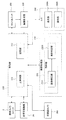
- Control system The configuration of the control system of the ophthalmologic apparatus 1 will be described with reference to FIG.
- the control system of the ophthalmologic apparatus 1 is configured around the control unit 210.
- the control unit 210 includes, for example, the aforementioned microprocessor, RAM, ROM, hard disk drive, communication interface, and the like.
- the control unit 210 includes a main control unit 211, a storage unit 212, an optical system position acquisition unit 213, and a movement information identification unit 214.
- the main control unit 211 performs the various operation controls described above.
- the movement control of the focusing lens 31 is to move the focusing lens 31 in the optical axis direction by controlling a focusing drive unit (not shown). Thereby, the focus position of the photographic optical system 30 is changed.
- the main control unit 211 can control the optical system driving unit 2A to move the optical system provided in the fundus camera unit 2 three-dimensionally.
- tracking refers to moving the apparatus optical system in accordance with the eye movement of the eye E. Tracking is performed, for example, at a later stage than alignment (in some cases, focusing is also performed in advance). Tracking is a function that maintains a suitable positional relationship in alignment (and focus) by causing the position of the apparatus optical system to follow the eye movement.
- optical system drive unit 2A of this embodiment moves an optical system mounted on the fundus camera unit 2, but the optical system mounted on the fundus camera unit 2 and the optical system mounted on the OCT unit 100. May be configured to be moved by the optical system driving unit 2A.
- the optical system drive unit 2A is an example of a “drive unit”.
- the anterior eye camera 300 of this embodiment is provided in the housing of the fundus camera unit 2, the anterior eye camera 300 can be moved by controlling the optical system driving part 2A. Further, it is possible to provide a photographing moving unit that can independently move two or more anterior eye camera 300.
- the imaging moving unit may include a drive mechanism (an actuator, a power transmission mechanism, etc.) provided for each anterior eye camera 300.
- the imaging moving unit is configured to move two or more anterior eye cameras 300 by transmitting power generated by a single actuator by a power transmission mechanism provided for each anterior eye camera 300. May be.
- the main control unit 211 performs a process of writing data to the storage unit 212 and a process of reading data from the storage unit 212.
- the storage unit 212 stores various data. Examples of the data stored in the storage unit 212 include OCT image image data, fundus image data, and examined eye information.
- the eye information includes information about the subject such as patient ID and name, and information about the eye such as left / right eye identification information.
- the storage unit 212 stores various programs and data for operating the ophthalmologic apparatus 1.
- Aberration information (not shown) is stored in the storage unit 212 in advance.
- information on distortion aberration generated in the captured image due to the influence of the optical system mounted on each anterior segment camera 300 is recorded.
- the optical system mounted on the anterior segment camera 300 includes an optical element that generates distortion, such as a lens.
- the aberration information can be said to be a parameter obtained by quantifying the distortion that these optical elements give to the photographed image.
- the operator prepares a predetermined reference point.
- the reference point is an imaging target used for detecting distortion.
- the operator performs multiple shootings while changing the relative position between the reference point and the anterior eye camera 300. Thereby, a plurality of captured images of the reference point captured from different directions are obtained.
- the operator generates aberration information of the anterior eye camera 300 by analyzing a plurality of acquired captured images with a computer.
- the computer that performs this analysis processing may be the image processing unit 230 or any other computer (an inspection computer before product shipment, a maintenance computer, etc.).
- the analysis process for generating aberration information includes, for example, the following steps: An extraction step of extracting an image region corresponding to the reference point from each captured image; A distribution state calculation step of calculating a distribution state (coordinates) of an image area corresponding to a reference point in each captured image; A distortion aberration calculating step of calculating a parameter representing distortion based on the obtained distribution state; A correction coefficient calculation step of calculating a coefficient for correcting distortion based on the obtained parameter.
- the parameters related to the distortion aberration given to the image by the optical system include principal point distance, principal point position (vertical direction, horizontal direction), lens distortion (radial direction, tangential direction), and the like.
- the aberration information is configured as information (for example, table information) in which the identification information of each anterior segment camera 300 is associated with the correction coefficient corresponding thereto.
- the aberration information generated in this way is stored in the storage unit 212 by the main control unit 211. Such generation of aberration information and correction of aberration based on the aberration information are called camera calibration.
- correspondence information 212a is stored in the storage unit 212 in advance.
- the movement direction and movement amount of the inspection optical system are associated with the displacement direction and displacement amount of the eye to be examined.
- the direction and amount of displacement of the eye to be examined indicate the displacement of the eye to be examined due to eye movement. Examples of eye movement include horizontal movement, vertical (vertical) movement, and rotational movement.
- the position of the inspection optical system is adjusted according to the state of the eye movement.
- the correspondence information 212a associates the state of eye movement (that is, the displacement direction and displacement amount of the eye to be examined) with the movement content (movement direction and movement amount) of the inspection optical system.
- the moving direction is a direction orthogonal to the optical axis of the inspection optical system. That is, the moving direction is an arbitrary direction in the xy plane shown in FIG.
- the correspondence information 212a is created, for example, by simulation.
- ray tracing can be performed while changing the displacement direction and amount of the model eye.
- the displacement direction is set equal to the displacement direction of the model eye.
- the amount of displacement is set by simulation.
- the optical distance between the position of the inspection light incident on the eye and the inspection position may change.
- the inspection light is incident on the eyeball from the vicinity of the top of the cornea and irradiated to the central part of the fundus, and when inspecting the peripheral part, The light enters the eyeball from the film and is irradiated to the periphery of the fundus.
- the incident position on the crystalline lens also affects the optical distance of the inspection light. Since the eyeball optical system is configured to be substantially rotationally symmetric with respect to the axis of the eyeball, the change in the optical distance is mainly affected by the amount of movement of the inspection optical system.
- a change in the optical distance corresponding to the movement amount of the inspection optical system can be obtained by simulation or the like, and can be used as the movement amount in the optical axis direction (z direction) of the inspection optical system.
- This movement amount is recorded in the correspondence information 212a as a correction amount for a predetermined working distance, for example.
- the working distance is a predetermined value called a working distance, and means a distance between the eye to be examined and the inspection optical system at the time of inspection using the inspection optical system.
- the displacement direction of the inspection optical system may include the rotation direction of the eye E, and the displacement amount may include the rotation amount of the eye E.
- the movement direction and the movement amount are associated with the rotation direction and the rotation amount. This correspondence is acquired by a simulation similar to the above, for example.
- the optical system position acquisition unit 213 acquires the current position of the inspection optical system mounted on the ophthalmologic apparatus 1.
- the inspection optical system is an optical system used to optically inspect the eye E.
- the inspection optical system in the ophthalmologic apparatus 1 (a combination machine of a fundus camera and an OCT apparatus) of this embodiment is an optical system for obtaining an image of the eye to be examined.
- the optical system position acquisition unit 213 receives, for example, information indicating the content of movement control of the optical system driving unit 2A by the main control unit 211, and acquires the current position of the inspection optical system moved by the optical system driving unit 2A. To do. A specific example of this process will be described.
- the main control unit 211 controls the optical system driving unit 2A at a predetermined timing (when the apparatus is activated, when patient information is input, etc.) to move the examination optical system to a predetermined initial position. Thereafter, each time the optical system driving unit 2A is controlled, the main control unit 211 records the control contents. Thereby, a history of control contents is obtained.
- the optical system position acquisition unit 213 acquires the control content up to the present with reference to this history, and obtains the current position of the inspection optical system based on the control content.
- the control content is transmitted to the optical system position acquisition unit 213, and each time the optical system position acquisition unit 213 receives the control content, the inspection optical system is transmitted.
- the current position may be obtained sequentially.
- a position sensor that detects the position of the inspection optical system may be provided in the optical system position acquisition unit 213.
- the main control unit 211 determines the acquired current position and the eye E to be examined obtained by the analysis unit 231 described later.
- the inspection optical system can be moved to the optical system driving unit 2A based on the three-dimensional position.
- the main control unit 211 recognizes the current position of the inspection optical system based on the acquisition result obtained by the optical system position acquisition unit 213, and recognizes the three-dimensional position of the eye E based on the analysis result obtained by the analysis unit 231.
- the main control unit 211 changes the position of the inspection optical system from the current position so that the position of the inspection optical system with respect to the three-dimensional position of the eye E has a predetermined positional relationship.
- This predetermined positional relationship is such that the positions in the x direction and the y direction coincide with each other and the distance in the z direction becomes a predetermined working distance.
- the analysis unit 231 acquires displacement information indicating a displacement direction and a displacement amount of the eye E to be examined by eye movement by analyzing a captured image acquired by the anterior eye camera 300.
- the movement information identification unit 214 identifies the movement direction and the movement amount corresponding to the displacement direction and the displacement amount indicated in the displacement information based on the correspondence information 212a. In this process, the movement direction and the movement amount associated with the displacement direction and the displacement amount indicated in the displacement information are searched from the correspondence relationship included in the correspondence information 212a.
- the image forming unit 220 forms tomographic image data of the fundus oculi Ef based on the detection signal from the CCD image sensor 115.
- This process includes processes such as noise removal (noise reduction), filter processing, FFT (Fast Fourier Transform), and the like, as in the conventional spectral domain type optical coherence tomography.
- the image forming unit 220 executes a known process corresponding to the type.
- the image forming unit 220 includes, for example, the circuit board described above. In this specification, “image data” and “image” based thereon may be identified.
- the image processing unit 230 performs various types of image processing and analysis processing on the image formed by the image forming unit 220. For example, the image processing unit 230 executes various correction processes such as image brightness correction and dispersion correction. The image processing unit 230 performs various types of image processing and analysis processing on the image (fundus image, anterior eye image, etc.) obtained by the fundus camera unit 2.
- the image processing unit 230 executes known image processing such as interpolation processing for interpolating pixels between tomographic images to form image data of a three-dimensional image of the fundus oculi Ef.
- image data of a three-dimensional image means image data in which pixel positions are defined by a three-dimensional coordinate system.
- image data of a three-dimensional image there is image data composed of voxels arranged three-dimensionally. This image data is called volume data or voxel data.
- the image processing unit 230 When displaying an image based on volume data, the image processing unit 230 performs a rendering process (such as volume rendering or MIP (Maximum Intensity Projection)) on the volume data, and views the image from a specific line-of-sight direction.
- Image data of a pseudo three-dimensional image is formed.
- the pseudo three-dimensional image is displayed on the display unit 240A.
- stack data of a plurality of tomographic images is image data of a three-dimensional image.
- the stack data is image data obtained by three-dimensionally arranging a plurality of tomographic images obtained along a plurality of scanning lines based on the positional relationship of the scanning lines. That is, stack data is image data obtained by expressing a plurality of tomographic images originally defined by individual two-dimensional coordinate systems by one three-dimensional coordinate system (that is, by embedding them in one three-dimensional space). is there.
- the image processing unit 230 is provided with an analysis unit 231.
- the analysis unit 231 obtains the three-dimensional position of the eye E by analyzing two captured images obtained substantially simultaneously by the anterior segment cameras 300A and 300B.
- the analysis unit 231 includes an image correction unit 2311, a feature point specification unit 2312, and a three-dimensional position calculation unit 2313.
- the analysis unit 231 obtains displacement information indicating the displacement direction and the displacement amount of the eye E to be examined by eye movement by analyzing the captured image obtained by the anterior eye camera 300.
- the analysis unit 231 includes a feature region specifying unit 2314, a shape information acquisition unit 2315, and a displacement information acquisition unit 2316.
- the image correction unit 2311 corrects the distortion of each captured image obtained by the anterior eye camera 300 based on the aberration information stored in the storage unit 212. This process is executed by, for example, a known image processing technique based on a correction coefficient for correcting distortion. Note that the aberration information and the image correction unit 2311 may not be provided when the distortion aberration given to the captured image by the optical system of the anterior segment camera 300 is sufficiently small.
- the feature point specifying unit 2312 analyzes each captured image (the distortion of which has been corrected by the image correcting unit 2311), thereby analyzing a position (feature point) in the captured image corresponding to a predetermined feature point of the anterior segment Ea. Is called).
- a predetermined feature point for example, the pupil center or corneal apex of the eye E is applied.
- the process of specifying the pupil center will be described.
- the feature point specifying unit 2312 specifies an image region (pupil region) corresponding to the pupil of the eye E based on the distribution of pixel values (such as luminance values) of the captured image.
- the pupil area can be specified by searching for the low brightness image area.
- the pupil region may be specified in consideration of the shape of the pupil. That is, the pupil region can be specified by searching for a substantially circular and low luminance image region.
- the feature point specifying unit 2312 specifies the center position of the specified pupil region. Since the pupil is substantially circular as described above, the contour of the pupil region can be specified, the center position of the approximate ellipse of this contour can be specified, and this can be used as the pupil center. Further, the center of gravity of the pupil region may be obtained, and the center of gravity position may be used as the center of the pupil.
- the position of the feature points can be specified based on the distribution of pixel values of the captured image in the same manner as described above.
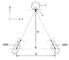
- the three-dimensional position calculation unit 2313 performs the feature of the eye E based on the positions of the two or more anterior segment cameras 300 and the positions of the feature points in the two or more captured images specified by the feature point specifying unit 2312. The three-dimensional position of the point is calculated. This process will be described with reference to FIGS. 5A and 5B.
- FIG. 5A is a top view showing the positional relationship between the eye E and the anterior eye cameras 300A and 300B.
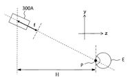
- FIG. 5B is a side view showing the positional relationship between the eye E and the anterior eye cameras 300A and 300B.
- the distance (baseline length) between the two anterior eye cameras 300A and 300B is represented by “B”.
- the distance (imaging distance) between the baselines of the two anterior eye cameras 300A and 300B and the characteristic part P of the eye E is represented by “H”.
- a distance (screen distance) between each anterior eye camera 300A and 300B and its screen plane is represented by “f”.
- the resolution of the captured image by the anterior segment cameras 300A and 300B is expressed by the following equation.
- ⁇ p represents pixel resolution.
- the three-dimensional position calculation unit 2313 is illustrated in FIGS. 5A and 5B with respect to the positions (known) of the two anterior eye cameras 300A and 300B and the position corresponding to the feature point P in the two captured images.
- the three-dimensional position of the feature point P that is, the three-dimensional position of the eye E to be examined is calculated.
- the three-dimensional position of the eye E calculated by the three-dimensional position calculation unit 2313 is sent to the control unit 210. Based on the calculation result of the three-dimensional position, the control unit 210 adjusts the optical axis of the inspection optical system to the axis of the eye E, and the distance of the inspection optical system with respect to the eye E is a predetermined operation.
- the optical system driving unit 2A is controlled so as to be a distance.
- the anterior eye camera 300 shoots a moving image of the anterior eye part Ea from different directions in parallel, for example, the following processes (1) and (2) are performed to test the movement of the eye E to be examined. It is possible to perform tracking of the optical system.
- the analysis unit 231 sequentially obtains the three-dimensional position of the eye E by sequentially analyzing two or more frames obtained substantially simultaneously in moving image shooting by the two or more anterior segment cameras 300. .
- the control unit 210 sequentially controls the optical system driving unit 2A based on the three-dimensional position of the eye E to be sequentially obtained by the analysis unit 231, thereby changing the position of the inspection optical system to the movement of the eye E. To follow.
- the feature region specifying unit 2314 specifies a feature region in the photographed image corresponding to the feature part of the anterior segment Ea by analyzing the photographed image acquired by the anterior segment camera 300. This process can be executed in the same manner as the feature point specifying unit 2312.
- Examples of the characteristic part of the anterior segment Ea include a pupil and an iris.
- a feature region corresponding to the pupil is referred to as a pupil region, and a feature region corresponding to the iris is referred to as an iris region.
- the feature region specifying unit 2314 may analyze the captured image that has been subjected to the above correction by the image correction unit 2311.
- the processing executed by the feature region specifying unit 2314 is a feature. Since it is included in the processing executed by the point specifying unit 2312, it is not necessary to provide the feature region specifying unit 2314. In that case, information on the feature region identified by the feature point identifying unit 2312 is input to the shape information acquiring unit 2315.
- shape information acquisition unit When inspecting the subject eye E in a state where eye movement is acting as in the case of inspecting the peripheral portion of the fundus oculi Ef, the shape of the characteristic region (pupil etc.) of the anterior segment Ea in the photographed image is It varies according to the displacement direction and displacement amount.
- the shape information acquisition unit 2315 acquires the shape of such a feature region.
- the shape information acquisition unit 2315 analyzes the feature region specified by the feature region specification unit 2314, thereby acquiring the shape information of the feature region. An example of this processing will be described.
- the shape information acquisition unit 2315 first obtains an approximate ellipse of the outline of the feature region (pupil region, iris region, etc.). This process can be executed in the same manner as the feature point specifying unit 2312, for example.
- the shape information acquisition unit 2315 calculates the major axis and minor axis of this approximate ellipse. This process is executed as follows, for example. First, the shape information acquisition unit 2315 obtains straight lines in various directions (tilts) passing through the center of the approximate ellipse, the first straight line having the longest line segment included in the approximate ellipse, and the shortest first line. 2 straight lines are identified. Furthermore, the shape information acquisition unit 2315 sets the length of the line segment in the first straight line as the major axis, and sets the length of the line segment in the second straight line as the minor axis.
- the length of the line segment is calculated as a distance (for example, the number of pixels) defined in the captured image, or as a distance obtained by converting this into a real space.
- the shape information of this embodiment includes information on the acquired major axis and minor axis. The shape information is not limited to this.
- the displacement information acquisition unit 2316 Based on the shape information acquired by the shape information acquisition unit 2315, the displacement information acquisition unit 2316 acquires displacement information indicating the displacement direction and the amount of displacement of the eye E due to eye movement. This process is executed with reference to, for example, information created in advance in which the information indicated by the shape information is associated with the displacement direction and the displacement amount. This information is called shape / displacement correspondence information.
- the shape / displacement correspondence information is created by, for example, obtaining the major axis and minor axis directions and the length ratio (ellipticity) corresponding to various directions of the eye to be examined or the model eye by simulation or actual measurement.
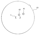
- a front image for example, an observation image
- This front image is obtained by photographing the anterior segment Ea in a state where the alignment index is projected. Therefore, the alignment index is depicted in this front image.
- FIGS. 6A and 6B An example of how the alignment index is drawn is shown in FIGS. 6A and 6B. 6A and 6B, the image of the eye E is omitted.
- the main control unit 211 superimposes and displays a bracket-shaped target image T indicating the alignment target position on the center position of the front image G1.
- the alignment index images A1 and A2 are drawn at positions away from the target image T. If the alignment in the z direction is shifted, the two alignment index images A1 and A2 are drawn at different positions. When all the alignments in the xyz direction are appropriate, the alignment index images A1 and A2 are drawn inside the target image T in a state of overlapping each other as shown in FIG. 6B.
- the displacement (displacement amount, displacement direction) of the alignment index images A1 and A2 with respect to the target image T indicates the alignment displacement (deviation amount, displacement direction) in the xy direction.
- the displacement (displacement amount, displacement direction) of the two alignment index images A1 and A2 indicates an alignment displacement (deviation amount, displacement direction) in the z direction.
- the analyzing unit 231 analyzes the front image G1 to obtain an alignment shift, and acquires an amount of movement of the optical system that cancels the shift. This process is executed as follows, for example. First, the analysis unit 231 specifies an image region corresponding to the alignment index images A1 and A2 based on the pixel information (luminance value and the like) of the front image G1. Next, the analysis unit 231 identifies the characteristic position (center, center of gravity, etc.) of each identified image region. Subsequently, the analysis unit 231 obtains the displacement of the feature position of each image region with respect to the center position of the target image T.
- the analysis unit 231 obtains an alignment deviation based on the obtained displacement, and obtains an amount of movement of the optical system that cancels the alignment deviation.
- the analysis unit 231 previously stores information that associates the displacement of the alignment index image defined in the coordinate system of the front image with the alignment shift defined in the coordinate system of the real space.
- the alignment shift can be obtained by referring to the information.
- the image processing unit 230 that functions as described above includes, for example, the aforementioned microprocessor, RAM, ROM, hard disk drive, circuit board, and the like.
- a storage device such as a hard disk drive, a computer program for causing the microprocessor to execute the above functions is stored in advance.
- the user interface 240 includes a display unit 240A and an operation unit 240B.
- the display unit 240A includes the display device of the arithmetic control unit 200 and the display device 3 described above.
- the operation unit 240B includes the operation device of the arithmetic control unit 200 described above.
- the operation unit 240B may include various buttons and keys provided on the housing of the ophthalmologic apparatus 1 or outside.
- the operation unit 240B may include a joystick, an operation panel, or the like provided on the housing.
- the display unit 240 ⁇ / b> A may include various display devices such as a touch panel provided on the housing of the fundus camera unit 2.
- the display unit 240A and the operation unit 240B do not need to be configured as individual devices.
- a device in which a display function and an operation function are integrated such as a touch panel
- the operation unit 240B includes the touch panel and a computer program.
- the operation content for the operation unit 240B is input to the control unit 210 as an electrical signal. Further, operations and information input may be performed using a graphical user interface (GUI) displayed on the display unit 240A and the operation unit 240B.
- GUI graphical user interface
- a first operation example will be described with reference to FIG.
- the second alignment for moving the inspection optical system based on the displacement information of the eye E.
- processing is executed.
- the inspection optical system is moved according to the spatial position of the eye E
- the inspection optical system is moved according to the state of eye movement of the eye E.
- Patient information includes patient ID, patient name, and the like.
- the examination type items include the examination site (fundus center, fundus periphery, optic disc, macular, etc.), eye to be examined (left eye, right eye, both eyes), image capturing pattern (fundus image only, OCT image only, Both), OCT scan patterns (line scan, cross scan, radial scan, circle scan, three-dimensional scan, etc.).
- the peripheral portion of the fundus oculi Ef is selected as the examination site. Note that, for example, when the center of the fundus is selected as the examination site, when the second alignment process is not necessary or when the necessity is low, only the first alignment process is performed. It is possible to perform control so as to.
- the start instruction may be automatically issued by the control unit 210 in response to the selection of the examination type shown in step 2, or may be manually given by the user using the operation unit 240B.
- the control unit 210 starts imaging of the anterior segment Ea by the anterior segment cameras 300A and 300B.
- This shooting is moving image shooting in which the anterior segment Ea is a shooting target.
- Each anterior eye camera 300A and 300B shoots a moving image at a predetermined frame rate.
- the imaging timings of the anterior eye cameras 300A and 300B may be synchronized by the control unit 210.
- Each anterior eye camera 300A and 300B sequentially sends the acquired frames to the control unit 210 in real time.
- the controller 210 associates the frames obtained by both anterior eye cameras 300A and 300B according to the photographing timing.
- control unit 210 associates frames acquired substantially simultaneously by both anterior eye cameras 300A and 300B. This association is executed, for example, based on the above-described synchronization control or based on the input timing of frames from the anterior eye cameras 300A and 300B.
- the control unit 210 sends a pair of associated frames to the analysis unit 231.
- the image correction unit 2311 corrects the distortion of each frame sent from the control unit 210 based on the aberration information stored in the storage unit 212. This correction processing is executed as described above. The pair of frames whose distortion has been corrected is sent to the feature point specifying unit 2312.
- the feature point specifying unit 2312 analyzes each frame sent from the image correction unit 2311 to execute processing for specifying a position in the frame corresponding to the feature point (pupil center) of the anterior segment Ea. To do.
- the feature point identification process is executed again after the anterior eye cameras 300A and 300B are moved in the direction away from the support unit 440 and / or the outside of the support unit 440. It is possible to control.
- the distance between the anterior eye cameras 300A and 300B and the subject (eye E) increases, and the face of the subject It is possible to shoot a wider range. Therefore, the possibility that the eye E is arranged in a suitable imageable range by the anterior eye cameras 300A and 300B increases.
- the anterior eye cameras 300A and 300B move in the direction of the subject's ear, and the eye to be examined is in a suitable photographing range.
- the possibility that E is arranged increases.
- the possibility that the eye E to be examined is arranged in a suitable photographing range is further increased. It should be noted that when this routine is repeated a predetermined number of times, control can be performed so as to shift to manual alignment.
- the movement control of the anterior segment cameras 300A and 300B similar to the above can be performed.
- the three-dimensional position calculation unit 2313 determines the feature point (pupil center) of the eye E based on the positions of the anterior eye cameras 300A and 300B and the position of the feature point specified for the pair of frames by the feature point specification unit 2312. ) Is calculated. This process is executed as described above.
- control unit 210 Based on the three-dimensional position of the center of the pupil calculated in step 6, the control unit 210 matches the optical axis of the inspection optical system with the axis of the eye E, and the inspection optical system for the eye E is inspected.
- the optical system driving unit 2A is controlled so that the distance becomes a predetermined working distance.
- the control unit 210 determines whether the position of the inspection optical system has converged. This determination process is performed using, for example, an alignment index.
- the observation state of the alignment index changes according to the alignment state. Specifically, in a state where the alignment is suitable, the two images of the alignment index are observed at substantially the same position, and the positions of the two images are observed apart as the alignment state deteriorates.
- the control unit 210 obtains a distance between two images taken by the CCD image sensor 35 and determines whether this distance is equal to or smaller than a predetermined threshold value. If it is determined that this distance is equal to or smaller than the predetermined threshold (S8: YES), it is determined that the position of the inspection optical system has converged, and the first alignment process ends, and the second alignment shown in step 9 is performed. Transition to processing.
- Steps 5 to 8 are repeated until, for example, “NO” is determined a predetermined number of times in step 8.
- the control unit 210 outputs, for example, predetermined warning information.
- step 8 When it is determined in step 8 that the position of the inspection optical system has converged (S8: YES), the control unit 210 ends the first alignment process and starts the second alignment process.
- the feature region specifying unit 2314 analyzes each frame sent from the image correction unit 2311 to specify a feature region (pupil region) in the frame corresponding to the feature part (pupil) of the anterior segment Ea.
- the shape information acquisition unit 2315 acquires the shape information of the feature region (pupil region) by analyzing the feature region identified in Step 10. This process is executed, for example, by obtaining the major axis and minor axis of the approximate ellipse of the pupil region.
- the displacement information acquisition unit 2316 acquires displacement information indicating the displacement direction and the amount of displacement of the eye E by eye movement based on the shape information acquired in step 11.
- the movement information identification unit 214 identifies the movement direction and the movement amount corresponding to the displacement direction and the displacement amount indicated in the displacement information acquired in Step 12 by referring to the correspondence information 212a. Then, the control unit 210 moves the inspection optical system in the movement direction by the movement direction by controlling the optical system driving unit 2A. This inspection optical system is moved in the xy plane. This completes the second alignment process.
- control unit 210 can also move the inspection optical system in the z direction by controlling the optical system driving unit 2A based on the movement amount. This movement of the inspection optical system in the z direction corresponds to the third alignment process.
- a second operation example will be described with reference to FIG.
- the success or failure of the first alignment process is determined.
- the first alignment process is unsuccessful, alignment using an alignment index is performed, and then the second alignment process is performed. is there.
- Steps 21 to 27 are executed in the same manner as steps 1 to 7 in the first operation example.
- the process proceeds to the alignment in step 29.
- the determination that the first alignment process has failed is made, for example, when the convergence determination process is repeated a predetermined number of times.
- step 28 If it is determined in step 28 that the first alignment process has failed, the controller 210 causes the above-described alignment to be executed.
- This alignment may be automatic alignment or manual alignment. Alternatively, first, auto alignment may be executed, and in response to the failure, manual alignment may be performed.
- Steps 31 to 37 are executed in the same manner as steps 9 to 15 in the first operation example. Thus, this operation example ends.
- the ophthalmologic apparatus 1 includes an examination optical system, an optical system drive unit 2A (drive unit), an anterior eye camera 300 (two or more imaging units), an analysis unit 231 and a control unit 210.
- the inspection optical system is an optical system for inspecting the eye E.
- the optical system driving unit 2A moves the inspection optical system.
- the anterior segment camera 300 images the anterior segment Ea of the eye E from substantially different directions at the same time.
- the analysis unit 231 obtains the three-dimensional position of the eye E by analyzing the captured image acquired by the anterior eye camera 300. Further, the analysis unit 231 obtains displacement information indicating the displacement direction and the displacement amount of the eye E to be examined by eye movement by analyzing the captured image obtained by the anterior eye camera 300.
- the control unit 210 controls the optical system driving unit 2 based on the three-dimensional position of the eye E acquired by the analysis unit 231 to move the inspection optical system (first alignment process). Further, the control unit 210 controls the optical system driving unit 2A based on the displacement information acquired by the analysis unit 231 to move the inspection optical system (second alignment process).
- the inspection optical system is aligned according to the spatial arrangement state of the eye E by the first alignment process, and the eye movement of the eye E by the second alignment process.
- the inspection optical system can be aligned according to the state. Therefore, precise positioning according to the state of the eye E can be performed, and the examination can be suitably performed.
- the displacement direction includes, for example, at least one of a horizontal direction, a vertical direction, and a rotation direction.
- the analysis unit 231 includes a feature region specifying unit 2314, a shape information acquisition unit 2315, and a displacement information acquisition unit 2316.
- the feature region specifying unit 2314 specifies a feature region in the photographed image corresponding to the feature part of the anterior segment Ea by analyzing the photographed image acquired by the anterior segment camera 300.
- the shape information acquisition unit 2315 acquires the shape information of the feature region by analyzing the specified feature region.
- the displacement information acquisition unit 2316 acquires displacement information indicating the displacement direction and the amount of displacement of the eye E by eye movement.
- the process for obtaining the displacement information is executed as follows, for example.
- the feature region specifying unit 2314 specifies the pupil region corresponding to the pupil or the iris region corresponding to the iris as the feature region.
- the shape information acquisition unit 2315 obtains an approximate ellipse of the outline of the specified pupil region or iris region, and acquires shape information by calculating the major axis and minor axis of the approximate ellipse.
- the displacement information acquisition unit 2316 obtains the displacement direction based on the major axis or minor axis direction indicated in the shape information, and obtains the displacement amount based on the ratio (ellipticity) between the major axis and the minor axis. This technique can be applied to any characteristic part of the anterior segment Ea having a shape that can be approximated to an ellipse.
- the analysis unit 231 includes a feature point specifying unit 2312 and a three-dimensional position calculation unit 2313.
- the feature point identifying unit 2312 identifies the position in the captured image corresponding to the feature point of the anterior segment Ea by analyzing two captured images acquired substantially simultaneously by the anterior segment cameras 300A and 300B. To do.
- the three-dimensional position calculation unit 2313 calculates the three-dimensional position of the feature point in the real space based on the position corresponding to the identified feature point and the positions of the anterior eye camera 300A and 300B. The calculation result of the three-dimensional position of the feature point is applied as the three-dimensional position of the eye E.
- a plurality of alignment processes are executed in this embodiment.
- the plurality of alignment processes are executed in the following order, for example.
- the control unit 210 can perform control so as to execute the second alignment process after executing the first alignment process. In this way, by performing the first alignment process and the second alignment process continuously, precise alignment can be performed quickly.
- the control unit 210 can perform control so as to execute alignment in response to the failure of the first alignment process, and then execute the second alignment process.
- the ophthalmologic apparatus 1 includes an alignment optical system 50 and a front image acquisition unit.
- the alignment optical system 50 projects the alignment index onto the anterior segment Ea.
- the front image acquisition unit acquires the front image of the anterior segment Ea by imaging the eye E with the alignment index projected thereon, and the illumination optical system 10 and the imaging optical system 30 correspond to this.
- the analysis unit 231 acquires the displacement of the inspection optical system with respect to the eye E by analyzing the acquired front image.
- the controller 210 determines whether the first alignment process is successful.
- the control unit 210 causes the second alignment process to be executed after executing the automatic alignment and / or the manual alignment. According to this example, even if the first alignment process fails, the spatial alignment of the inspection optical system with respect to the eye E is performed by alignment, and then the second alignment process is performed. It is possible.
- the success or failure of the first alignment process is influenced by the height of the nose, the degree of eye depression, and further by mascara and eye shadow.
- the control unit 210 includes a storage unit 212 (first storage unit) and a movement information specifying unit 214 (first movement information specifying unit).
- correspondence information 212a first correspondence information
- the movement information specifying unit 214 specifies the movement direction and the movement amount corresponding to the displacement direction and the displacement amount shown in the displacement information acquired by the analysis unit 231 based on the correspondence information 212a.
- the control unit 210 controls the optical system driving unit 2A so as to move the inspection optical system by the amount of movement in the movement direction specified by the movement information specifying unit 214.
- the moving direction in the second alignment process is, for example, a direction orthogonal to the optical axis of the inspection optical system (that is, an arbitrary direction in the xy plane).
- the control unit 210 can move the inspection optical system in the direction of the optical axis of the inspection optical system (that is, the z direction) based on the amount of movement of the inspection optical system in the second alignment process ( Third alignment process). This third alignment process is to compensate for the shift in working distance due to the second alignment process.
- the matching process is executed.
- This second alignment process is performed by analyzing captured images acquired by two or more imaging units.
- the second alignment process is executed based on the projection position of the fixation target.
- the same reference numerals are used for the same components as those in the first embodiment.
- the ophthalmologic apparatus 1 of this embodiment has a hardware configuration similar to that of the first embodiment, for example (see FIGS. 1 and 2).
- a configuration example of a control system of the ophthalmologic apparatus 1 of this embodiment is shown in FIG.
- the main difference from the control system of the first embodiment shown in FIG. 3 is that the feature region specifying unit 2314, the shape information acquiring unit 2315, and the displacement information acquiring unit 2316 are not provided. That is, the analysis unit 231 of this embodiment does not acquire displacement information used for the second alignment process.
- parts different from the first embodiment will be mainly described.
- the fixation optical system includes a fixation target presenting unit (LCD 39) for presenting a fixation target and a fixation target projection optical system for projecting the presented fixation target onto the eye E.
- the fixation target projection optical system is configured by an optical element that forms an optical path between the LCD 39 and the eye E.
- the fixation target projection optical system of this example includes a half mirror 39A, a mirror 32, a focusing lens 31, an objective lens 22, and the like.
- the control unit 210 displays a fixation target at the position of the LCD 39 corresponding to the examination site designated by the user, for example.
- the examination site and the display position of the fixation target are associated in advance.
- the display position of the fixation target can be arbitrarily changed using the operation unit 240B.
- correspondence information 212a as second correspondence information is stored in advance.
- the correspondence information 212a of this embodiment associates the movement direction and movement amount of the inspection optical system with the projection position of the fixation target.
- the projection position of the fixation target corresponds to the fixation position (fixation direction) or the inspection position of the eye to be examined.
- Correspondence information 212a is created based on the results of simulation and actual measurement, as in the first embodiment.
- the correspondence information 212a is created only when the eye movement is sufficiently applied, for example, when examining the fundus periphery.
- the correspondence information 212a may be associated with a movement direction and a movement amount for each of a plurality of fixation target display positions on the LCD 39.
- the plurality of display positions may be all positions at which the fixation target can be displayed on the LCD 39, or may be a part of the positions (for example, the fixation position is separated from the fundus center by a predetermined distance or more). Only if you have).
- the movement information specifying unit 214 of this embodiment uses the movement direction and movement amount of the inspection optical system corresponding to the projection position as correspondence information 212a. Identify based on.
- a first operation example will be described with reference to FIG.
- the second alignment for moving the inspection optical system based on the projection position of the fixation target.
- a case where processing is executed will be described.
- the inspection optical system is moved in accordance with the spatial position of the eye E, and in the second alignment process, the inspection optical system is in alignment with the fixation position for inducing eye movement of the eye E. Move the optical system.
- Steps 41 to 49 are executed in the same manner as steps 1 to 9 in the first operation example. That is, the first alignment process and the transition process from the first alignment process to the second alignment process are the same as in the first embodiment.
- the inspection position that is, the fixation position
- the control unit 210 controls the LCD 39 to display a fixation target at a display position corresponding to the selected fixation position.
- the movement information identification unit 214 refers to the correspondence information 212a and identifies the movement direction and movement amount corresponding to the fixation target projection position selected by the fixation optical system selected in Step 42.
- the control unit 210 moves the inspection optical system by controlling the optical system driving unit 2A based on the movement direction and the movement amount specified in step 50.
- Steps 52 and 53 are executed in the same manner as Steps 14 and 15 in the first operation example. Thus, this operation example ends.
- a second operation example will be described with reference to FIG.
- the success or failure of the first alignment process is determined.
- the first alignment process is unsuccessful, alignment using an alignment index is performed, and then the second alignment process is performed. is there.
- Steps 61 to 67 are executed in the same manner as steps 41 to 47 in the first operation example.
- step 67 the controller 210 performs a convergence determination process similar to step 8 of the first alignment process. If it is determined that convergence has occurred, that is, if it is determined that the first alignment process has been successful (S68: YES), the process proceeds to the second alignment process shown in step 71.
- the process proceeds to the alignment in step 69.
- the determination that the first alignment process has failed is made, for example, when the convergence determination process is repeated a predetermined number of times.
- step 68 If it is determined in step 68 that the first alignment process has failed, the control unit 210 causes the same alignment as in the first embodiment to be executed. Upon completion of the alignment, the control unit 210 proceeds to the second alignment process shown in step 71.
- Steps 71 to 75 are executed in the same manner as Steps 49 to 53 in the first operation example. Thus, this operation example ends.
- the ophthalmologic apparatus 1 includes an examination optical system, an optical system drive unit 2A (drive unit), a fixation optical system, an anterior eye camera 300 (two or more imaging units), an analysis unit 231, and a control unit 210. And have.
- the inspection optical system is an optical system for inspecting the eye E.
- the optical system driving unit 2A moves the inspection optical system.
- the fixation optical system projects a fixation target for visual line guidance onto the eye to be examined.
- the anterior segment camera 300 images the anterior segment Ea of the eye E from substantially different directions at the same time.
- the analysis unit 231 acquires the three-dimensional position of the eye E by analyzing the captured image acquired by the anterior eye camera 300.
- the control unit 210 performs a process of changing the projection position of the fixation target by controlling the fixation optical system.
- control unit 210 controls the optical system driving unit 2A based on the three-dimensional position of the eye E acquired by the analysis unit 231 to move the inspection optical system (first alignment process). Further, the control unit 210 moves the inspection optical system by controlling the optical system driving unit 2A based on the projection position of the fixation target (second alignment process).
- the inspection optical system is aligned according to the spatial arrangement state of the eye E by the first alignment process, and the eye movement of the eye E by the second alignment process.
- the optical system for inspection can be aligned in accordance with the fixation position that leads to a predetermined state. Therefore, precise positioning according to the state of the eye E can be performed, and the examination can be suitably performed.
- the control unit 210 includes a storage unit 212 (second storage unit) and a movement information specifying unit 214 (second movement information specifying unit).
- the storage unit 212 correspondence information 212a in which the movement direction and movement amount of the inspection optical system are associated with the projection position of the fixation target is stored in advance.
- the movement information specifying unit 214 specifies the movement direction and the movement amount corresponding to the projection position of the fixation target by the fixation optical system based on the correspondence information 212a.
- the control unit 210 performs the second alignment process based on the specified moving direction and moving amount.
- the fixation optical system includes an LCD 39 (fixation target presenting unit) and a fixation target projection optical system.
- the LCD 39 can present fixation targets at a plurality of positions.
- the fixation target projection optical system projects the presented fixation target onto the eye E.
- the movement direction and the movement amount of the inspection optical system are associated with each of the plurality of positions.
- the control unit 210 controls the LCD 39 to present a fixation target at any of the plurality of positions.
- the movement information identification unit 214 identifies the movement direction and the movement amount corresponding to the position where the fixation target is presented by the control unit 210 based on the correspondence information 212a.
- a plurality of alignment processes are executed in this embodiment.
- the plurality of alignment processes are executed in the following order, for example.
- the control unit 210 can perform control so as to execute the second alignment process after executing the first alignment process. In this way, by performing the first alignment process and the second alignment process continuously, precise alignment can be performed quickly.
- the control unit 210 can perform control so as to execute alignment in response to the failure of the first alignment process, and then execute the second alignment process.
- the ophthalmologic apparatus 1 includes an alignment optical system 50 and a front image acquisition unit.
- the alignment optical system 50 projects the alignment index onto the anterior segment Ea.
- the front image acquisition unit acquires the front image of the anterior segment Ea by imaging the eye E with the alignment index projected thereon, and the illumination optical system 10 and the imaging optical system 30 correspond to this.
- the analysis unit 231 acquires the displacement of the inspection optical system with respect to the eye E by analyzing the acquired front image.
- the controller 210 determines whether the first alignment process is successful.
- control unit 210 causes the second alignment process to be executed after executing the automatic alignment and / or the manual alignment. According to this example, even if the first alignment process fails, the spatial alignment of the inspection optical system with respect to the eye E is performed by alignment, and then the second alignment process is performed. It is possible.
- the moving direction of the inspection optical system in the second alignment process may be a direction orthogonal to the optical axis of the inspection optical system (that is, the xy direction).
- the control unit 210 can move the inspection optical system in the direction of the optical axis of the inspection optical system (that is, the z direction) based on the amount of movement of the inspection optical system in the second alignment process.
- Yes third alignment process. This third alignment process is to compensate for the shift in working distance due to the second alignment process.
- a feature point specifying unit 2312 and a three-dimensional position calculating unit 2313 similar to those in the first embodiment may be provided. Is possible.
- the ophthalmologic apparatus 1 of this embodiment has a hardware configuration similar to that of the first embodiment, for example (see FIGS. 1 and 2).
- An example of the configuration of the control system of the ophthalmologic apparatus 1 of this embodiment is shown in FIG. In this example, a configuration that can switch between an operation mode for a normal pupil eye having a general pupil diameter and an operation mode for a small pupil eye will be described.
- the operation mode information 212b is stored in the storage unit 212 in advance.
- various control contents are associated with pupil information indicating the state of the pupil.
- Pupil information includes pupil size (pupil diameter, etc.) and pupil shape.
- the control contents include fixation light intensity, observation light intensity, photographing light intensity, aperture, position of the inspection optical system, and the like.
- the fixation light intensity indicates the intensity of the projected light flux of the fixation target with respect to the eye E.
- the fixation light intensity is controlled by controlling the light emission intensity of the LCD 39, for example.
- the observation light intensity indicates the intensity of the observation illumination light.
- the observation light intensity is performed by controlling the emission intensity of the observation light source 11, for example.
- the photographing light intensity indicates the intensity of photographing illumination light.
- the photographing light intensity is controlled by controlling the output intensity of the photographing light source 15.
- the diaphragm control is, for example, switching control between a diaphragm for a normal pupil eye and a diaphragm for a small pupil eye.
- This diaphragm control includes control for selectively applying two diaphragms having different aperture sizes and control of a diaphragm capable of changing the aperture size.
- the stop to be controlled is, for example, the stop 19 of the illumination optical system 10 shown in FIG.
- the position of the inspection optical system is shifted in the case of a small pupil eye. Note that the shift amount can be changed according to the pupil size.
- FIG. 1 An example of the operation mode information 212a is shown in FIG.
- this operation mode information 212b as control contents corresponding to the normal mode applied to the normal pupil eye, fixation light intensity “a1”, observation light intensity “b1”, photographing light intensity “c1”, aperture “I”
- the optical system position “no shift” is associated.
- fixation light intensity “a2”, observation light intensity “b2”, photographing light intensity “c2”, aperture “III” optical system position “With shift” is associated.
- the fixation light intensity, the observation light intensity, and the photographing light intensity are defined by the value of the light intensity or an amount equivalent to the value (voltage value, current value, charge amount, etc.).
- the diaphragms “I” and “II” indicate identification information given to the two diaphragms. It is also possible to apply a shift amount instead of the optical system position “with shift”.
- the analysis unit 231 includes an image correction unit 2311, a pupil region specifying unit 2317, and a pupil information acquisition unit 2318.
- the image correction unit 2311 performs the same process as in the first embodiment.
- the pupil region specifying unit 2317 performs processing similar to the pupil region specifying processing (feature point specifying unit 2312) described in the first embodiment.
- the pupil information acquisition unit 2318 analyzes the pupil region specified by the pupil region specification unit 2317 and acquires the pupil size and the pupil shape. The acquisition of the pupil size is performed, for example, in the same manner as the processing in which the shape information acquisition unit 2315 of the second embodiment obtains the major axis of the approximate ellipse of the contour of the pupil region.
- the acquisition of the pupil shape is performed in the same manner as the processing for obtaining the ellipticity of the approximate ellipse of the outline of the pupil region, for example, by the shape information acquisition unit 2315.
- the analysis unit 231 performs a process of obtaining a three-dimensional position of the eye E by analyzing the captured image acquired by the anterior eye camera 300, as in the first embodiment.
- the control unit 210 executes alignment processing for controlling the optical system driving unit 2A based on the three-dimensional position of the eye E acquired by the analysis unit 231 to move the inspection optical system.
- the control unit 210 executes an optical system control process for controlling the optical system based on the pupil information acquired by the analysis unit 231. Examples of the control target of this optical system include the above-described fixation light intensity, observation light intensity, photographing light intensity, stop, and position of the inspection optical system.
- Steps 81 to 88 are executed in the same manner as Steps 1 to 8 in the first operation example.
- the alignment process the first alignment process of the first embodiment
- the transition to the subsequent process are the same as in the first embodiment.
- the analysis unit 231 acquires the pupil information of the eye E by performing, for example, the above process.
- the pupil information includes the pupil size and the pupil shape.
- the control unit 210 selects the normal mode or the small pupil mode based on the pupil information acquired in step 90. For example, this process compares the pupil size acquired in step 90 with a preset threshold value, selects the normal mode when the pupil size exceeds the threshold value, and reduces the pupil size when the pupil size is equal to or smaller than the threshold value. This is done by selecting the pupil mode.
- the control unit 210 acquires the control content corresponding to the operation mode selected in step 91 from the operation mode information 212b. Then, each of the fixation light intensity, the observation light intensity, the photographing light intensity, the stop, and the optical system position is controlled based on the acquired control content.
- Step 93 and step 94 are executed in the same manner as step 14 and step 15 of the first operation example. Thus, this operation example ends.
- the ophthalmologic apparatus 1 includes an optical system, an optical system drive unit 2A (drive unit), an anterior eye camera 300 (two or more imaging units), an analysis unit 231, and a control unit 210.
- the optical system includes an inspection optical system for inspecting the eye E.
- the optical system driving unit 2A moves the inspection optical system.
- the anterior segment camera 300 images the anterior segment Ea of the eye E from substantially different directions at the same time.
- the analysis unit 231 obtains the three-dimensional position of the eye E by analyzing the captured image acquired by the anterior eye camera 300.
- the analysis unit 231 acquires pupil information indicating the state of the pupil of the eye E by analyzing the captured image acquired by the anterior segment camera 300.
- the control unit 210 controls the optical system driving unit 2A based on the three-dimensional position of the eye E acquired by the analysis unit 231 to move the inspection optical system (positioning process).
- the control unit 210 controls the optical system based on the pupil information acquired by the analysis unit 231 (optical system control process).
- the alignment of the examination optical system is performed according to the spatial arrangement state of the eye E by the alignment process, and the state of the pupil of the eye E is determined by the optical system control process.
- the optical system can be controlled. Therefore, precise alignment and control according to the state of the eye E can be performed, and the examination can be suitably performed.
- the operation mode can be automatically changed according to the state of the pupil. Further, by analyzing a plurality of captured images acquired from different directions by the anterior eye camera 300, the state of the pupil of the eye E can be acquired with high accuracy and high accuracy.
- Optical system control processing includes, for example, control of one or more of fixation light intensity, observation light intensity, photographing light intensity, aperture, and optical system position.
- the optical system includes a fixation optical system that projects a fixation target for visual line guidance onto the eye to be examined.
- the analysis unit 231 acquires the pupil size as pupil information.
- the controller 210 controls the fixation optical system based on the acquired pupil size to change the intensity of the projected light flux of the fixation target.
- the optical system is disposed coaxially with the inspection optical system, and is disposed coaxially with the illumination optical system 10 (first illumination optical system) that irradiates the observation eye E with observation illumination light (continuous light) and the inspection optical system. And a photographing optical system 30 (first photographing optical system) for photographing a moving image of the eye E to which the observation illumination light is irradiated.
- the illumination optical system 10 and the imaging optical system 30 are included in the inspection optical system.
- the analysis unit 231 acquires the pupil size as pupil information.
- the control unit 210 changes the intensity of the observation illumination light by controlling the illumination optical system 10 based on the acquired pupil size.
- the optical system is disposed coaxially with the inspection optical system, and is disposed coaxially with the illumination optical system 10 (second illumination optical system) for irradiating the eye E with photographing illumination light (flash light) and the inspection optical system.
- a photographing optical system 30 (second photographing optical system) for photographing the eye E in synchronization with the irradiation of the photographing illumination light.
- the illumination optical system 10 and the imaging optical system 30 are included in the inspection optical system.
- the analysis unit 231 acquires the pupil size as pupil information.
- the controller 210 controls the illumination optical system 10 based on the acquired pupil size to change the intensity of the imaging illumination light.
- the optical system includes an illumination optical system 10 (third illumination optical system) that is arranged coaxially with the inspection optical system, includes two or more diaphragms (diaphragm 19) having different aperture sizes, and irradiates the eye E with illumination light. And an imaging optical system 30 (third imaging optical system) which is arranged coaxially with the inspection optical system and images the eye E to which the illumination light is irradiated.
- the illumination optical system 10 and the imaging optical system 30 are included in the inspection optical system.
- the analysis unit 231 acquires the pupil size as pupil information.
- the controller 210 selectively places the two or more stops in the optical path of the illumination optical system 10 based on the acquired pupil size.
- the analysis unit 231 acquires a pupil shape as pupil information.
- the control unit 210 controls the drive unit based on the acquired pupil shape to move the examination optical system. This movement control may include a process according to another embodiment.
- the ophthalmologic apparatus 1 of this embodiment has a hardware configuration similar to that of the first embodiment, for example (see FIGS. 1 and 2).
- a configuration example of the control system of the ophthalmologic apparatus 1 of this embodiment is shown in FIG.
- the analysis unit 231 includes an image correction unit 2311 and a blink determination unit 2319.
- the image correction unit 2311 performs the same processing as in the first embodiment.
- the blink determination unit 2319 determines the presence or absence of blink of the eye E by analyzing a captured image acquired by the anterior eye camera 300. This process is executed as follows, for example. First, the blink determination unit 2319 analyzes a captured image and identifies a pupil region (or iris region). This process is executed in the same manner as in the first embodiment, for example. When the pupil region is not specified, the blink determination unit 2319 determines that the eye E is blinking. When the pupil region is specified, the blink determination unit 2319 obtains shape information indicating the shape of the pupil region.
- the blink determination unit 2319 determines the presence or absence of blinks based on the shape information. This process is executed based on, for example, the diameter of the pupil region in the vertical direction (y direction). The blink determination unit 2319 determines that the eye E is blinking when the diameter in the vertical direction is equal to or smaller than the predetermined threshold value, and the eye E is blinking when the diameter in the vertical direction exceeds the predetermined threshold value. Judge that there is no. As another processing example, the ratio of the diameter in the vertical direction (y direction) to the diameter in the horizontal direction (x direction) of the pupil region is obtained.
- the blink determination unit 2319 determines that the eye E is blinking when the ratio value is equal to or less than the predetermined threshold value, and the eye E is blinking when the ratio value exceeds the predetermined threshold value. Judge that there is no.
- the analysis unit 231 performs a process of obtaining a three-dimensional position of the eye E by analyzing the captured image acquired by the anterior eye camera 300, as in the first embodiment.
- the ophthalmologic apparatus 1 notifies the determination result by the blink determination unit 2319.
- the control unit 210 causes the display unit 240A to display predetermined warning information when the blink determination unit 2319 determines that the eye E is blinking.
- This warning information is character string information or image information indicating blinking or alerting.
- the aspect of display information can be switched with the case where it is set as the case where it is not blinking. It is also possible to change the correspondence of the display information according to the blinking time. For example, when the blink duration exceeds a predetermined threshold, the display information mode can be switched.
- the ophthalmologic apparatus 1 includes an inspection optical system, an optical system drive unit 2A (drive unit), an anterior eye camera 300 (two or more imaging units), an analysis unit 231, and a notification unit.
- the inspection optical system is an optical system for inspecting the eye E.
- the optical system driving unit 2A moves the inspection optical system.
- the anterior segment camera 300 images the anterior segment Ea of the eye E from substantially different directions at the same time.
- the analysis unit 231 acquires the three-dimensional position of the eye E by analyzing the captured image acquired by the anterior segment camera 300. Further, the analysis unit 231 determines the presence or absence of blink of the eye E by analyzing the captured image acquired by the anterior segment camera 300.
- the notification unit notifies the determination result by the analysis unit 231.
- the notification unit includes a display unit 240A and a control unit 210.
- the control unit 210 displays warning information on the display unit 240A.
- the notification mode is not limited to this. For example, not only such visual information but also auditory information can be output.
- the anterior eye camera 300 (imaging unit) can be arranged below the lens center of the objective lens 22 ( ⁇ y direction). Thereby, it is possible to reduce the possibility that the eyelashes and eyelashes of the subject are reflected in the captured image acquired by the anterior eye camera 300 (imaging unit). Moreover, even if the subject has a deep eye depression (orbit), anterior segment imaging can be suitably performed.
- two captured images acquired substantially simultaneously by the anterior eye cameras 300A and 300B can be combined by the image processing unit 230, and this combined image can be displayed. Thereby, it is possible to observe the three-dimensional form of the anterior segment Ea. Moreover, the analysis process of the said embodiment can also be performed using this synthesized image.
- control unit 210 can display at least one of the two captured images obtained substantially simultaneously by the anterior segment cameras 300A and 300B. Thereby, the form of the anterior segment Ea can be observed from different viewpoints (imaging positions).
- the anterior eye camera 300 may be mounted on the front surface of the housing 420 or may be stored in the housing 420. That is, the anterior eye camera 300 may be disposed so as to protrude from the front surface of the housing 420 or may be disposed substantially flush with the front surface of the housing 420. Note that the anterior eye camera 300 may be provided so that the front surface is disposed at a position depressed with respect to the front surface of the housing 420.
- the anterior eye camera 300A is provided so as not to protrude from the front surface of the housing 420, there are advantages that it does not interfere with eye opening or external fixation operation, and that an automatic alignment failure due to vignetting of the image itself can be avoided. .
- the anterior eye camera 300 at a position other than the front surface of the housing 420.
- the anterior eye camera 300 can be provided in the housing 420 and a similar optical system can be provided. When such an optical system is provided, it is considered that it is desirable to provide the anterior eye camera 300 and the optical system in the housing 420 in consideration of disturbance to the anterior eye photographing.
- an optical path separation member such as a prism or a dichroic mirror can be used for separation of the optical system.
- the optical path length difference between the optical path of the signal light LS and the optical path of the reference light LR is changed by changing the position of the optical path length changing unit 41, but this optical path length difference is changed.
- the method is not limited to this.
- it is possible to change the optical path length difference by disposing a reflection mirror (reference mirror) in the optical path of the reference light and moving the reference mirror in the traveling direction of the reference light to change the optical path length of the reference light.
- the optical path length difference may be changed by moving the fundus camera unit 2 or the OCT unit 100 with respect to the eye E to change the optical path length of the signal light LS.
- the computer program for realizing the above embodiment can be stored in an arbitrary recording medium readable by a computer.
- this recording medium for example, a semiconductor memory, an optical disk, a magneto-optical disk (CD-ROM / DVD-RAM / DVD-ROM / MO, etc.), a magnetic storage medium (hard disk / floppy (registered trademark) disk / ZIP, etc.), etc. Can be used.
Landscapes
- Health & Medical Sciences (AREA)
- Life Sciences & Earth Sciences (AREA)
- Engineering & Computer Science (AREA)
- Molecular Biology (AREA)
- Animal Behavior & Ethology (AREA)
- Biophysics (AREA)
- Ophthalmology & Optometry (AREA)
- Biomedical Technology (AREA)
- Heart & Thoracic Surgery (AREA)
- Medical Informatics (AREA)
- Veterinary Medicine (AREA)
- Surgery (AREA)
- Physics & Mathematics (AREA)
- General Health & Medical Sciences (AREA)
- Public Health (AREA)
- Human Computer Interaction (AREA)
- Signal Processing (AREA)
- Eye Examination Apparatus (AREA)
- Nuclear Medicine, Radiotherapy & Molecular Imaging (AREA)
- Radiology & Medical Imaging (AREA)
Abstract
被検眼の状態に応じて検査を好適に行うことが可能な眼科装置を提供する。実施形態の眼科装置は、検査用光学系と、駆動部と、2以上の撮影部と、解析部と、制御部とを有する。検査用光学系は、被検眼を検査するための光学系である。駆動部は、検査用光学系を移動する。2以上の撮影部は、被検眼の前眼部を異なる方向から実質的に同時に撮影する。解析部は、2以上の撮影部により取得された撮影画像を解析することにより、被検眼の3次元位置と、眼球運動による被検眼の変位方向および変位量を示す変位情報とを取得する。制御部は、3次元位置に基づき駆動部を制御して検査用光学系を移動させる第1位置合わせ処理と、変位情報に基づき駆動部を制御して検査用光学系を移動させる第2位置合わせ処理とを実行する。
Description
この発明は眼科装置に関する。
眼科装置には、被検眼の画像を得るための眼科撮影装置と、被検眼の特性を測定するための眼科測定装置が含まれる。
眼科撮影装置の例として、光コヒーレンストモグラフィ(Optical Coherence Tomography、OCT)を用いて断層像を得る光干渉断層計、眼底を写真撮影する眼底カメラ、共焦点光学系を用いたレーザ走査により眼底の画像を得る走査型レーザ検眼鏡(Scanning Laser Ophthalmoscope、SLO)、スリット光を用いて角膜の光切片を切り取ることにより画像を得るスリットランプなどがある。
また、眼科測定装置の例として、被検眼の屈折特性を測定する眼屈折検査装置(レフラクトメータ、ケラトメータ)、眼圧計、角膜の特性(角膜厚、細胞分布等)を得るスペキュラーマイクロスコープ、ハルトマン-シャックセンサを用いて被検眼の収差情報を得るウェーブフロントアナライザなどがある。
これら装置を用いた眼科検査においては、検査の精度や確度の観点から、装置光学系と被検眼との位置合わせが極めて重要である。この位置合わせはアライメントと呼ばれる。アライメントには、被検眼の軸に対して装置光学系の光軸を一致させる動作(xyアライメント)と、被検眼と装置光学系との間の距離を合わせる動作(zアライメント)とが含まれる。
従来のアライメントは被検眼の状態を考慮せずに行われるため、検査を好適に行えないことがあった。たとえば、眼底の周辺部を撮影するときのように被検眼の視線方向が変位している場合、眼底検査用の光束が虹彩に遮られてデータを得られないことや、眼底の撮影画像にフレアが混入することがあった。また、被検眼の縮瞳状態や瞼の状態についても、検査に悪影響を及ぼすことがあった。
この発明の目的は、被検眼の状態に応じて検査を好適に行うことが可能な眼科装置を提供することにある。
請求項1に記載の発明は、被検眼を検査するための検査用光学系と、前記検査用光学系を移動する駆動部と、被検眼の前眼部を異なる方向から実質的に同時に撮影する2以上の撮影部と、前記2以上の撮影部により取得された撮影画像を解析することにより、被検眼の3次元位置と、眼球運動による被検眼の変位方向および変位量を示す変位情報とを取得する解析部と、前記3次元位置に基づき前記駆動部を制御して前記検査用光学系を移動させる第1位置合わせ処理と、前記変位情報に基づき前記駆動部を制御して前記検査用光学系を移動させる第2位置合わせ処理とを実行する制御部とを有する眼科装置である。
請求項2に記載の発明は、請求項1に記載の眼科装置であって、前記解析部は、前記撮影画像を解析することで、前眼部の特徴部位に相当する当該撮影画像中の特徴領域を特定する特徴領域特定部と、特定された特徴領域を解析することで、当該特徴領域の形状情報を取得する形状情報取得部と取得された形状情報に基づいて前記変位情報を取得する変位情報取得部とを含むことを特徴とする。
請求項3に記載の発明は、請求項2に記載の眼科装置であって、前記特徴領域特定部は、前記特徴領域として、瞳孔に相当する瞳孔領域または虹彩に相当する虹彩領域を特定し、前記形状情報取得部は、特定された瞳孔領域または虹彩領域について、その輪郭の近似楕円を求め、当該近似楕円の長径および短径を算出することで前記形状情報を求め、前記変位情報取得部は、長軸または短軸の方向に基づいて前記変位方向を求め、長軸と短軸との比に基づいて前記変位量を求めることで前記変位情報を取得することを特徴とする。
請求項4に記載の発明は、請求項1~請求項3のいずれか一項に記載の眼科装置であって、前記解析部は、前記2以上の撮影部により実質的に同時に取得された2以上の撮影画像を解析することで、前眼部の特徴点に相当する当該撮影画像中の位置を特定する特徴点特定部と、特定された前記特徴点に相当する位置および前記2以上の撮影部の位置に基づいて前記特徴点の3次元位置を算出する3次元位置算出部とを含み、算出された前記特徴点の3次元位置を前記被検眼の3次元位置とすることを特徴とする。
請求項5に記載の発明は、請求項1~請求項4のいずれか一項に記載の眼科装置であって、前記制御部は、前記第1位置合わせ処理を実行した後に前記第2位置合わせ処理を実行することを特徴とする。
請求項6に記載の発明は、請求項1~請求項4のいずれか一項に記載の眼科装置であって、被検眼に対する前記検査用光学系のアライメントを行なうためのアライメント指標を前眼部に投影するアライメント光学系と、アライメント指標が投影されている状態の被検眼を撮影して前眼部の正面画像を取得する正面画像取得部と、を有し、前記解析部は、前記正面画像を解析することで、被検眼に対する前記検査用光学系の変位を取得し、前記制御部は、前記第1位置合わせ処理の成否を判定し、失敗と判定された場合、前記検査用光学系の変位に基づき前記駆動部を制御してアライメントを実行した後に前記第2位置合わせ処理を実行することを特徴とする。
請求項7に記載の発明は、請求項1~請求項6のいずれか一項に記載の眼科装置であって、前記制御部は、被検眼の変位方向および変位量に対して前記検査用光学系の移動方向および移動量が対応付けられた第1対応情報をあらかじめ記憶した第1記憶部と、前記解析部により取得された変位情報に示す変位方向および変位量に対応する移動方向および移動量を前記第1対応情報に基づいて特定する第1移動情報特定部とを含み、特定された移動方向および移動量に基づいて前記第2位置合わせ処理を実行することを特徴とする。
請求項8に記載の発明は、請求項7に記載の眼科装置であって、前記移動方向は、前記検査用光学系の光軸に直交する方向であることを特徴とする。
請求項9に記載の発明は、請求項8に記載の眼科装置であって、前記制御部は、前記移動量に基づき前記駆動部を制御して前記検査用光学系を前記光軸の方向に移動させる第3位置合わせ処理を実行することを特徴とする。
請求項10に記載の発明は、請求項1~請求項9のいずれか一項に記載の眼科装置であって、前記変位方向は、被検眼の回旋方向を含み、前記変位量は、被検眼の回旋量を含むことを特徴とする。
請求項11に記載の発明は、被検眼を検査するための検査用光学系と、前記検査用光学系を移動する駆動部と、視線誘導用の固視標を被検眼に投影する固視光学系と、被検眼の前眼部を異なる方向から実質的に同時に撮影する2以上の撮影部と、前記2以上の撮影部により取得された撮影画像を解析することにより被検眼の3次元位置を取得する解析部と、前記固視光学系を制御して前記固視標の投影位置を変更する処理と、前記3次元位置に基づき前記駆動部を制御して前記検査用光学系を移動させる第1位置合わせ処理と、前記固視標の投影位置に基づき前記駆動部を制御することで前記検査用光学系を移動させる第2位置合わせ処理とを実行する制御部とを有する眼科装置である。
請求項12に記載の発明は、請求項11に記載の眼科装置であって、前記制御部は、固視標の投影位置に対して前記検査用光学系の移動方向および移動量が対応付けられた第2対応情報をあらかじめ記憶した第2記憶部と、前記固視光学系による固視標の投影位置に対応する移動方向および移動量を前記第2対応情報に基づいて特定する第2移動情報特定部とを含み、特定された移動方向および移動量に基づいて前記第2位置合わせ処理を実行することを特徴とする。
請求項13に記載の発明は、請求項12に記載の眼科装置であって、前記固視光学系は、複数の位置に固視標を呈示可能な固視標呈示部と、呈示された固視標を被検眼に投影する固視標投影光学系とを含み、前記第2対応情報には、前記複数の位置のそれぞれに対して移動方向および移動量が対応付けられており、前記制御部は、前記固視標呈示部を制御して、前記複数の位置のいずれかに固視標を呈示させ、前記第2移動情報特定部は、前記制御部により固視標が呈示された位置に対応する移動方向および移動量を前記第2対応情報に基づいて特定することを特徴とする。
請求項14に記載の発明は、請求項12または請求項13に記載の眼科装置であって、前記移動方向は、前記検査用光学系の光軸に直交する方向であることを特徴とする。
請求項15に記載の発明は、請求項14に記載の眼科装置であって、前記制御部は、前記移動量に基づき前記駆動部を制御して前記検査用光学系を前記光軸の方向に移動させる第3位置合わせ処理を実行することを特徴とする。
請求項16に記載の発明は、請求項11~請求項15のいずれか一項に記載の眼科装置であって、前記制御部は、前記第1位置合わせ処理を実行した後に前記第2位置合わせ処理を実行することを特徴とする。
請求項17に記載の発明は、請求項11~請求項15のいずれか一項に記載の眼科装置であって、被検眼に対する前記検査用光学系のアライメントを行なうためのアライメント指標を前眼部に投影するアライメント光学系と、アライメント指標が投影されている状態の被検眼を撮影して前眼部の正面画像を取得する正面画像取得部とを有し、解析部は、前記正面画像を解析することで、被検眼に対する前記検査用光学系の変位を取得し、前記制御部は、前記第1位置合わせ処理の成否を判定し、失敗と判定された場合、前記検査用光学系の変位に基づき前記駆動部を制御してアライメントを実行した後に前記第2位置合わせ処理を実行することを特徴とする。
請求項18に記載の発明は、被検眼を検査するための検査用光学系を含む光学系と、前記検査用光学系を移動する駆動部と、被検眼の前眼部を異なる方向から実質的に同時に撮影する2以上の撮影部と、前記2以上の撮影部により取得された撮影画像を解析することにより、被検眼の3次元位置と、被検眼の瞳孔の状態を示す瞳孔情報とを取得する解析部と、前記3次元位置に基づき前記駆動部を制御して前記検査用光学系を移動させる位置合わせ処理と、前記瞳孔情報に基づいて前記光学系を制御する光学系制御処理とを実行する制御部とを有する眼科装置である。
請求項19に記載の発明は、請求項18に記載の眼科装置であって、前記光学系は、視線誘導用の固視標を被検眼に投影する固視光学系を含み、前記解析部は、前記瞳孔情報として瞳孔サイズを取得し、前記制御部は、前記光学系制御処理として、取得された瞳孔サイズに基づき前記固視光学系を制御して前記固視標の投影光束の強度を変更することを特徴とする。
請求項20に記載の発明は、請求項18に記載の眼科装置であって、前記光学系は、前記検査用光学系と同軸に配置され、被検眼に連続光を照射する第1照明光学系と、前記検査用光学系と同軸に配置され、前記連続光が照射されている被検眼を動画撮影する第1撮影光学系とを含み、前記解析部は、前記瞳孔情報として瞳孔サイズを取得し、前記制御部は、前記光学系制御処理として、取得された瞳孔サイズに基づき前記第1照明光学系を制御して前記連続光の強度を変更することを特徴とする。
請求項21に記載の発明は、請求項18に記載の眼科装置であって、前記光学系は、前記検査用光学系と同軸に配置され、被検眼にフラッシュ光を照射する第2照明光学系と、前記検査用光学系と同軸に配置され、前記フラッシュ光の照射に同期して被検眼を撮影する第2撮影光学系とを含み、前記解析部は、前記瞳孔情報として瞳孔サイズを取得し、前記制御部は、前記光学系制御処理として、取得された瞳孔サイズに基づき前記第2照明光学系を制御して前記フラッシュ光の強度を変更することを特徴とする。
請求項22に記載の発明は、請求項18に記載の眼科装置であって、前記光学系は、前記検査用光学系と同軸に配置され、開口サイズが異なる2以上の絞りを含み、被検眼に照明光を照射する第3照明光学系と、前記検査用光学系と同軸に配置され、前記照明光が照射されている被検眼を撮影する第3撮影光学系とを含み、前記解析部は、前記瞳孔情報として瞳孔サイズを取得し、前記制御部は、前記光学系制御処理として、取得された瞳孔サイズに基づき前記第3照明光学系の光路に前記2以上の絞りを選択的に配置させることを特徴とする。
請求項23に記載の発明は、請求項18に記載の眼科装置であって、前記解析部は、前記瞳孔情報として瞳孔形状を取得し、前記制御部は、前記光学系制御処理として、取得された瞳孔形状に基づき前記駆動部を制御して前記検査用光学系を移動させることを特徴とする。
請求項24に記載の発明は、被検眼を検査するための検査用光学系と、前記検査用光学系を移動する駆動部と、被検眼の前眼部を異なる方向から実質的に同時に撮影する2以上の撮影部と、前記2以上の撮影部により取得された撮影画像を解析することにより、被検眼の3次元位置を取得する処理と、被検眼の瞬きの有無を判定する処理とを実行する解析部と、前記解析部による判定結果を報知する報知部とを有する眼科装置である。
請求項25に記載の発明は、請求項24に記載に眼科装置であって、前記報知部は、表示部と、前記解析部により被検眼が瞬きしていると判定されたときに、前記表示部に警告情報を表示させる制御部と、を含むことを特徴とする。
なお、上記した発明を任意に組み合わせることが可能である。
この発明によれば、被検眼の状態に応じて検査を好適に行うことが可能である。
この発明に係る眼科装置の実施形態の一例について、図面を参照しながら詳細に説明する。この発明に係る眼科装置は被検眼の光学的な検査に用いられる。このような眼科装置には、前述のように、眼科撮影装置と眼科測定装置が含まれる。眼科撮影装置としては、光干渉断層計、眼底カメラ、走査型レーザ検眼鏡スリットランプなどがある。また、眼科測定装置としては、眼屈折検査装置、眼圧計、スペキュラーマイクロスコープ、ウェーブフロントアナライザなどがある。以下の実施形態では、光干渉断層計にこの発明を適用した場合について詳述するが、それ以外の任意の眼科装置にこの発明を適用することが可能である。
この明細書において、OCTによって取得される画像をOCT画像と総称することがある。また、OCT画像を形成するための計測動作をOCT計測と呼ぶことがある。なお、この明細書に記載された文献の記載内容を、以下の実施形態の内容として適宜援用することが可能である。
また、以下の実施形態では、低コヒーレンス光源と分光器が搭載された、いわゆるスペクトラルドメイン(Spectral Domain)タイプのOCTを用いた光干渉断層計について説明するが、スペクトラルドメイン以外のタイプ、たとえばスウェプトソースタイプ、インファスタイプのOCTの手法を用いた光干渉断層計に対してこの発明を適用することも可能である。なお、スウェプトソース(Swept Source)OCTとは、被測定物体に照射される光の波長を走査(波長掃引)し、各波長の光の反射光と参照光とを重ね合わせて得られる干渉光を検出してスペクトル強度分布を取得し、それに対してフーリエ変換を施すことにより被測定物体の形態を画像化する手法である。また、インファス(en-face)OCTとは、所定のビーム径を有する光を被測定物体に照射し、その反射光と参照光とを重ね合わせて得られる干渉光の成分を解析することにより、光の進行方向に直交する断面における被測定物体の画像を形成する手法であり、フルフィールド(full-field)タイプとも呼ばれる。
また、以下の実施形態ではOCT装置と眼底カメラとを組み合わせた装置について説明するが、この発明の適用対象はこのような複合機には限定されず、単体機としての眼科装置(たとえば眼底カメラ単体)にこの発明を適用することも可能である。
〈第1の実施形態〉
[構成]
図1に示すように、眼科装置1は、眼底カメラユニット2、OCTユニット100および演算制御ユニット200を含んで構成される。眼底カメラユニット2は、従来の眼底カメラとほぼ同様の光学系を有する。OCTユニット100には、眼底のOCT画像を取得するための光学系が設けられている。演算制御ユニット200は、各種の演算処理や制御処理等を実行するコンピュータを具備している。
[構成]
図1に示すように、眼科装置1は、眼底カメラユニット2、OCTユニット100および演算制御ユニット200を含んで構成される。眼底カメラユニット2は、従来の眼底カメラとほぼ同様の光学系を有する。OCTユニット100には、眼底のOCT画像を取得するための光学系が設けられている。演算制御ユニット200は、各種の演算処理や制御処理等を実行するコンピュータを具備している。
〔眼底カメラユニット〕
図1に示す眼底カメラユニット2には、被検眼Eの眼底Efの表面形態を表す2次元画像(眼底像)を取得するための光学系が設けられている。眼底像には、観察画像や撮影画像などが含まれる。観察画像は、たとえば、近赤外光を用いて所定のフレームレートで形成されるモノクロの動画像である。なお、被検眼Eの前眼部Eaに光学系のピントが合っている場合、眼底カメラユニット2は前眼部Eaの観察画像を取得することができる。撮影画像は、たとえば、可視光をフラッシュ発光して得られるカラー画像、または近赤外光若しくは可視光を照明光として用いたモノクロの静止画像であってもよい。眼底カメラユニット2は、これら以外の画像、たとえばフルオレセイン蛍光画像やインドシアニングリーン蛍光画像や自発蛍光画像などを取得可能に構成されていてもよい。
図1に示す眼底カメラユニット2には、被検眼Eの眼底Efの表面形態を表す2次元画像(眼底像)を取得するための光学系が設けられている。眼底像には、観察画像や撮影画像などが含まれる。観察画像は、たとえば、近赤外光を用いて所定のフレームレートで形成されるモノクロの動画像である。なお、被検眼Eの前眼部Eaに光学系のピントが合っている場合、眼底カメラユニット2は前眼部Eaの観察画像を取得することができる。撮影画像は、たとえば、可視光をフラッシュ発光して得られるカラー画像、または近赤外光若しくは可視光を照明光として用いたモノクロの静止画像であってもよい。眼底カメラユニット2は、これら以外の画像、たとえばフルオレセイン蛍光画像やインドシアニングリーン蛍光画像や自発蛍光画像などを取得可能に構成されていてもよい。
眼底カメラユニット2には、被検者の顔を支持するための顎受けと額当てが設けられている。顎受けおよび額当ては、図4Aおよび図4Bに示す支持部440に相当する。なお、図4Aおよび図4Bにおいて、符号410は、光学系駆動部2A等の駆動系や、演算制御回路が格納されたベースを示す。また、符号420は、ベース410上に設けられた、光学系が格納された筐体を示す。また、符号430は、筐体420の前面に突出して設けられた、対物レンズ22が収容されたレンズ収容部を示す。
眼底カメラユニット2には、照明光学系10と撮影光学系30が設けられている。照明光学系10は眼底Efに照明光を照射する。撮影光学系30は、この照明光の眼底反射光を撮像装置(CCDイメージセンサ(単にCCDと呼ぶことがある)35、38。)に導く。また、撮影光学系30は、OCTユニット100からの信号光を眼底Efに導くとともに、眼底Efを経由した信号光をOCTユニット100に導く。
照明光学系10の観察光源11は、たとえばハロゲンランプにより構成される。観察光源11から出力された光(観察照明光)は、曲面状の反射面を有する反射ミラー12により反射され、集光レンズ13を経由し、可視カットフィルタ14を透過して近赤外光となる。更に、観察照明光は、撮影光源15の近傍にて一旦集束し、ミラー16により反射され、リレーレンズ17、18、絞り19およびリレーレンズ20を経由する。そして、観察照明光は、孔開きミラー21の周辺部(孔部の周囲の領域)にて反射され、ダイクロイックミラー46を透過し、対物レンズ22により屈折されて眼底Efを照明する。なお、観察光源としてLED(Light Emitting Diode)を用いることも可能である。
観察照明光の眼底反射光は、対物レンズ22により屈折され、ダイクロイックミラー46を透過し、孔開きミラー21の中心領域に形成された孔部を通過し、ダイクロイックミラー55を透過し、合焦レンズ31を経由し、ミラー32により反射される。更に、この眼底反射光は、ハーフミラー39Aを透過し、ダイクロイックミラー33により反射され、集光レンズ34によりCCDイメージセンサ35の受光面に結像される。CCDイメージセンサ35は、たとえば所定のフレームレートで眼底反射光を検出する。表示装置3には、CCDイメージセンサ35により検出された眼底反射光に基づく画像(観察画像)が表示される。なお、撮影光学系のピントが前眼部に合わせられている場合、被検眼Eの前眼部Eaの観察画像が表示される。観察画像は、前眼部Eaを被検者の正面から撮影して得られる正面画像の一例である。
撮影光源15は、たとえばキセノンランプにより構成される。撮影光源15から出力された光(撮影照明光)は、観察照明光と同様の経路を通って眼底Efに照射される。撮影照明光の眼底反射光は、観察照明光のそれと同様の経路を通ってダイクロイックミラー33まで導かれ、ダイクロイックミラー33を透過し、ミラー36により反射され、集光レンズ37によりCCDイメージセンサ38の受光面に結像される。表示装置3には、CCDイメージセンサ38により検出された眼底反射光に基づく画像(撮影画像)が表示される。なお、観察画像を表示する表示装置3と撮影画像を表示する表示装置3は、同一のものであってもよいし、異なるものであってもよい。また、被検眼Eを赤外光で照明して同様の撮影を行う場合には、赤外の撮影画像が表示される。また、撮影光源としてLEDを用いることも可能である。撮影画像は、前眼部Eaを被検者の正面から撮影して得られる正面画像の一例である。
LCD(Liquid Crystal Display)39は、固視標や視力測定用指標を表示する。固視標は被検眼Eを固視させるための指標であり、眼底撮影時やOCT計測時などに使用される。
LCD39から出力された光は、その一部がハーフミラー39Aにて反射され、ミラー32に反射され、合焦レンズ31およびダイクロイックミラー55を経由し、孔開きミラー21の孔部を通過し、ダイクロイックミラー46を透過し、対物レンズ22により屈折されて眼底Efに投影される。
LCD39の画面上における固視標の表示位置を変更することにより、被検眼Eに対する固視標の投影方向、つまり被検眼Eの固視位置を変更できる。被検眼Eの固視位置としては、たとえば従来の眼底カメラと同様に、眼底Efの黄斑部を中心とする画像を取得するための位置や、視神経乳頭を中心とする画像を取得するための位置や、黄斑部と視神経乳頭との間の眼底中心を中心とする画像を取得するための位置などがある。また、固視標の表示位置を任意に変更することも可能である。
なお、被検眼Eに固視標を投影する手段はこれには限定されない。たとえば、複数のLEDを配列してなるLED群を設け、これらLEDを選択的に点灯させることにより固視位置を変更することができる。また、移動可能な1つ以上のLEDを設けることにより固視位置を変更することも可能である。
更に、眼底カメラユニット2には、従来の眼底カメラと同様にアライメント光学系50とフォーカス光学系60が設けられている。アライメント光学系50は、被検眼Eに対する装置光学系の位置合わせ(アライメント)を行うための指標(アライメント指標)を生成する。フォーカス光学系60は、眼底Efに対してフォーカス(ピント)を合わせるための指標(スプリット指標)を生成する。
アライメント光学系50のLED51から出力された光(アライメント光)は、絞り52、53およびリレーレンズ54を経由してダイクロイックミラー55により反射され、孔開きミラー21の孔部を通過し、ダイクロイックミラー46を透過し、対物レンズ22により被検眼Eの角膜に投影される。
アライメント光の角膜反射光は、対物レンズ22、ダイクロイックミラー46および上記孔部を経由し、その一部がダイクロイックミラー55を透過し、合焦レンズ31を通過し、ミラー32により反射され、ハーフミラー39Aを透過し、ダイクロイックミラー33に反射され、集光レンズ34によりCCDイメージセンサ35の受光面に投影される。CCDイメージセンサ35による受光像(アライメント指標)は、観察画像とともに表示装置3に表示される。ユーザは、従来の眼底カメラと同様の操作を行ってアライメントを実施する。また、演算制御ユニット200がアライメント指標の位置を解析して光学系を移動させることによりアライメントを行ってもよい(オートアライメント機能)。なお、この実施形態では、後述の前眼部カメラ300を用いてオートアライメントを実行することができるので、アライメント指標を用いたオートアライメントが可能なことは必須な事項ではない。ただし、前眼部カメラ300を用いたオートアライメントが成功しなかったときにアライメント指標を用いたオートアライメントを行えるように構成したり、前眼部カメラ300を用いたオートアライメントとアライメント指標を用いたオートアライメントとを選択的に使用できるように構成したりすることも可能である。
フォーカス調整を行う際には、照明光学系10の光路上に反射棒67の反射面が斜設される。フォーカス光学系60のLED61から出力された光(フォーカス光)は、リレーレンズ62を通過し、スプリット指標板63により2つの光束に分離され、二孔絞り64を通過し、ミラー65に反射され、集光レンズ66により反射棒67の反射面に一旦結像されて反射される。更に、フォーカス光は、リレーレンズ20を経由し、孔開きミラー21に反射され、ダイクロイックミラー46を透過し、対物レンズ22により屈折されて眼底Efに投影される。
フォーカス光の眼底反射光は、アライメント光の角膜反射光と同様の経路を通ってCCDイメージセンサ35により検出される。CCDイメージセンサ35による受光像(スプリット指標)は、観察画像とともに表示装置3に表示される。演算制御ユニット200は、従来と同様に、スプリット指標の位置を解析して合焦レンズ31およびフォーカス光学系60を移動させてピント合わせを行う(オートフォーカス機能)。また、スプリット指標を視認しつつ手動でピント合わせを行ってもよい。
ダイクロイックミラー46は、眼底撮影用の光路からOCT計測用の光路を分岐させる。ダイクロイックミラー46は、OCT計測に用いられる波長帯の光を反射し、眼底撮影用の光を透過させる。このOCT計測用の光路には、OCTユニット100側から順に、コリメータレンズユニット40と、光路長変更部41と、ガルバノスキャナ42と、合焦レンズ43と、ミラー44と、リレーレンズ45とが設けられている。
光路長変更部41は、図1に示す矢印の方向に移動可能とされ、OCT計測用の光路の光路長を変更する。この光路長の変更は、被検眼Eの眼軸長に応じた光路長の補正や、干渉状態の調整などに利用される。光路長変更部41は、たとえばコーナーキューブと、これを移動する機構とを含んで構成される。
ガルバノスキャナ42は、OCT計測用の光路を通過する光(信号光LS)の進行方向を変更する。それにより、眼底Efを信号光LSで走査することができる。ガルバノスキャナ42は、たとえば、信号光LSをx方向に走査するガルバノミラーと、y方向に走査するガルバノミラーと、これらを独立に駆動する機構とを含んで構成される。それにより、信号光LSをxy平面上の任意の方向に走査することができる。
眼底カメラユニット2には前眼部カメラ300が設けられている。前眼部カメラ300は、前眼部Eaを異なる方向から実質的に同時に撮影する。この実施形態では、眼底カメラユニット2の被検者側の面に2台のカメラが設けられている(図4Aに示す前眼部カメラ300A、300Bを参照)。また、前眼部カメラ300Aおよび300Bはそれぞれ、図1および図4Aに示すように、照明光学系10の光路および撮影光学系30の光路から外れた位置に設けられている。以下、2台の前眼部カメラ300Aおよび300Bをまとめて符号300で表すことがある。
この実施形態では、2台の前眼部カメラ300Aおよび300Bが設けられているが、この発明における前眼部カメラの個数は2以上の任意の個数である。しかし、後述の演算処理を考慮すると、異なる2方向から実質的に同時に前眼部を撮影可能な構成であれば十分である。また、この実施形態では、照明光学系10および撮影光学系30とは別個に前眼部カメラ300を設けているが、少なくとも撮影光学系30を用いて同様の前眼部撮影を行うことができる。つまり、2以上の前眼部カメラのうちの1つを撮影光学系30を含む構成によって担うようにしてもよい。いずれにしても、この実施形態は、異なる2(以上の)方向から実質的に同時に前眼部を撮影可能に構成されていればよい。
なお、「実質的に同時」とは、2以上の前眼部カメラによる撮影において、眼球運動を無視できる程度の撮影タイミングのズレを許容することを示す。それにより、被検眼Eが実質的に同じ位置(向き)にあるときの画像を2以上の前眼部カメラによって取得することができる。
また、2以上の前眼部カメラによる撮影は動画撮影でも静止画撮影でもよいが、この実施形態では動画撮影を行う場合について特に詳しく説明する。動画撮影の場合、撮影開始タイミングを合わせるよう制御したり、フレームレートや各フレームの撮影タイミングを制御したりすることにより、上記した実質的に同時の前眼部撮影を実現することができる。一方、静止画撮影の場合、撮影タイミングを合わせるよう制御することにより、これを実現することができる。
〔OCTユニット〕
図2を参照しつつOCTユニット100の構成の一例を説明する。OCTユニット100には、眼底EfのOCT画像を取得するための光学系が設けられている。この光学系は、従来のスペクトラルドメインタイプのOCT装置と同様の構成を有する。すなわち、この光学系は、低コヒーレンス光を参照光と信号光に分割し、眼底Efを経由した信号光と参照光路を経由した参照光とを干渉させて干渉光を生成し、この干渉光のスペクトル成分を検出するように構成されている。この検出結果(検出信号)は演算制御ユニット200に送られる。
図2を参照しつつOCTユニット100の構成の一例を説明する。OCTユニット100には、眼底EfのOCT画像を取得するための光学系が設けられている。この光学系は、従来のスペクトラルドメインタイプのOCT装置と同様の構成を有する。すなわち、この光学系は、低コヒーレンス光を参照光と信号光に分割し、眼底Efを経由した信号光と参照光路を経由した参照光とを干渉させて干渉光を生成し、この干渉光のスペクトル成分を検出するように構成されている。この検出結果(検出信号)は演算制御ユニット200に送られる。
なお、スウェプトソースタイプのOCT装置の場合には、低コヒーレンス光源を出力する光源の代わりに波長掃引光源が設けられるとともに、干渉光をスペクトル分解する光学部材が設けられない。一般に、OCTユニット100の構成については、OCTのタイプに応じた公知の技術を任意に適用することができる。
光源ユニット101は広帯域の低コヒーレンス光L0を出力する。低コヒーレンス光L0は、たとえば、近赤外領域の波長帯(約800nm~900nm程度)を含み、数十マイクロメートル程度の時間的コヒーレンス長を有する。なお、人眼では視認できない波長帯、たとえば1040~1060nm程度の中心波長を有する近赤外光を低コヒーレンス光L0として用いてもよい。
光源ユニット101は、スーパールミネセントダイオード(Super Luminescent Diode:SLD)や、LEDや、SOA(Semiconductor Optical Amplifier)等の光出力デバイスを含んで構成される。
光源ユニット101から出力された低コヒーレンス光L0は、光ファイバ102によりファイバカプラ103に導かれて信号光LSと参照光LRに分割される。
参照光LRは、光ファイバ104により導かれて光減衰器(アッテネータ)105に到達する。光減衰器105は、公知の技術を用いて、演算制御ユニット200の制御の下、光ファイバ104に導かれる参照光LRの光量を自動で調整する。光減衰器105により光量が調整された参照光LRは、光ファイバ104により導かれて偏波調整器(偏波コントローラ)106に到達する。偏波調整器106は、たとえば、ループ状にされた光ファイバ104に対して外部から応力を与えることで、光ファイバ104内を導かれる参照光LRの偏光状態を調整する装置である。なお、偏波調整器106の構成はこれに限定されるものではなく、任意の公知技術を用いることが可能である。偏波調整器106により偏光状態が調整された参照光LRは、ファイバカプラ109に到達する。
ファイバカプラ103により生成された信号光LSは、光ファイバ107により導かれ、コリメータレンズユニット40により平行光束とされる。更に、信号光LSは、光路長変更部41、ガルバノスキャナ42、合焦レンズ43、ミラー44、およびリレーレンズ45を経由してダイクロイックミラー46に到達する。そして、信号光LSは、ダイクロイックミラー46により反射され、対物レンズ22により屈折されて眼底Efに照射される。信号光LSは、眼底Efの様々な深さ位置において散乱(反射を含む)される。眼底Efによる信号光LSの後方散乱光は、往路と同じ経路を逆向きに進行してファイバカプラ103に導かれ、光ファイバ108を経由してファイバカプラ109に到達する。
ファイバカプラ109は、信号光LSの後方散乱光と、光ファイバ104を経由した参照光LRとを干渉させる。これにより生成された干渉光LCは、光ファイバ110により導かれて出射端111から出射される。更に、干渉光LCは、コリメータレンズ112により平行光束とされ、回折格子113により分光(スペクトル分解)され、集光レンズ114により集光されてCCDイメージセンサ115の受光面に投影される。なお、図2に示す回折格子113は透過型であるが、たとえば反射型の回折格子など、他の形態の分光素子を用いることも可能である。
CCDイメージセンサ115は、たとえばラインセンサであり、分光された干渉光LCの各スペクトル成分を検出して電荷に変換する。CCDイメージセンサ115は、この電荷を蓄積して検出信号を生成し、これを演算制御ユニット200に送る。
この実施形態ではマイケルソン型の干渉計を採用しているが、たとえばマッハツェンダー型など任意のタイプの干渉計を適宜に採用することが可能である。また、CCDイメージセンサに代えて、他の形態のイメージセンサ、たとえばCMOS(Complementary Metal Oxide Semiconductor)イメージセンサなどを用いることが可能である。
〔演算制御ユニット〕
演算制御ユニット200の構成について説明する。演算制御ユニット200は、CCDイメージセンサ115から入力される検出信号を解析して眼底EfのOCT画像を形成する。そのための演算処理は、従来のスペクトラルドメインタイプのOCT装置と同様である。
演算制御ユニット200の構成について説明する。演算制御ユニット200は、CCDイメージセンサ115から入力される検出信号を解析して眼底EfのOCT画像を形成する。そのための演算処理は、従来のスペクトラルドメインタイプのOCT装置と同様である。
また、演算制御ユニット200は、眼底カメラユニット2、表示装置3およびOCTユニット100の各部を制御する。たとえば演算制御ユニット200は、眼底EfのOCT画像を表示装置3に表示させる。
また、眼底カメラユニット2の制御として、演算制御ユニット200は、観察光源11、撮影光源15およびLED51、61の動作制御、LCD39の動作制御、合焦レンズ31、43の移動制御、反射棒67の移動制御、フォーカス光学系60の移動制御、光路長変更部41の移動制御、ガルバノスキャナ42の動作制御、前眼部カメラ300の動作制御などを行う。
また、OCTユニット100の制御として、演算制御ユニット200は、光源ユニット101の動作制御、光減衰器105の動作制御、偏波調整器106の動作制御、CCDイメージセンサ115の動作制御などを行う。
演算制御ユニット200は、たとえば、従来のコンピュータと同様に、マイクロプロセッサ、RAM、ROM、ハードディスクドライブ、通信インターフェイスなどを含んで構成される。ハードディスクドライブ等の記憶装置には、眼科装置1を制御するためのコンピュータプログラムが記憶されている。演算制御ユニット200は、各種の回路基板、たとえばOCT画像を形成するための回路基板を備えていてもよい。また、演算制御ユニット200は、キーボードやマウス等の操作デバイス(入力デバイス)や、LCD等の表示デバイスを備えていてもよい。
眼底カメラユニット2、表示装置3、OCTユニット100および演算制御ユニット200は、一体的に(つまり単一の筺体内に)構成されていてもよいし、2つ以上の筐体に別れて構成されていてもよい。
〔制御系〕
眼科装置1の制御系の構成について図3を参照しつつ説明する。
眼科装置1の制御系の構成について図3を参照しつつ説明する。
(制御部)
眼科装置1の制御系は、制御部210を中心に構成される。制御部210は、たとえば、前述のマイクロプロセッサ、RAM、ROM、ハードディスクドライブ、通信インターフェイス等を含んで構成される。制御部210には、主制御部211と、記憶部212と、光学系位置取得部213と、移動情報特定部214とが設けられている。
眼科装置1の制御系は、制御部210を中心に構成される。制御部210は、たとえば、前述のマイクロプロセッサ、RAM、ROM、ハードディスクドライブ、通信インターフェイス等を含んで構成される。制御部210には、主制御部211と、記憶部212と、光学系位置取得部213と、移動情報特定部214とが設けられている。
(主制御部)
主制御部211は前述した各種の動作制御を行う。なお、合焦レンズ31の移動制御は、図示しない合焦駆動部を制御して合焦レンズ31を光軸方向に移動させるものである。それにより、撮影光学系30の合焦位置が変更される。また、主制御部211は、光学系駆動部2Aを制御して、眼底カメラユニット2に設けられた光学系を3次元的に移動させることができる。
主制御部211は前述した各種の動作制御を行う。なお、合焦レンズ31の移動制御は、図示しない合焦駆動部を制御して合焦レンズ31を光軸方向に移動させるものである。それにより、撮影光学系30の合焦位置が変更される。また、主制御部211は、光学系駆動部2Aを制御して、眼底カメラユニット2に設けられた光学系を3次元的に移動させることができる。
この制御は、オートアライメントやトラッキングにおいて実行される。ここで、トラッキングとは、被検眼Eの眼球運動に合わせて装置光学系を移動させるものである。トラッキングは、たとえばアライメントよりも後の段階で実行される(場合によってはピント合わせも事前に実行される)。トラッキングは、装置光学系の位置を眼球運動に追従させることにより、アライメント(およびピント)が合った好適な位置関係を維持する機能である。
なお、この実施形態の光学系駆動部2Aは眼底カメラユニット2に搭載された光学系を移動させるものであるが、眼底カメラユニット2に搭載された光学系およびOCTユニット100に搭載された光学系を光学系駆動部2Aにより移動させるように構成されていてもよい。光学系駆動部2Aは「駆動部」の一例である。
また、この実施形態の前眼部カメラ300は眼底カメラユニット2の筐体に設けられているので、光学系駆動部2Aを制御することにより前眼部カメラ300を移動させることができる。また、2以上の前眼部カメラ300をそれぞれ独立に移動させることが可能な撮影移動部を設けることができる。具体的には、撮影移動部は、各前眼部カメラ300に対して設けた駆動機構(アクチュエータ、動力伝達機構等)を含む構成であってもよい。また、撮影移動部は、単一のアクチュエータにより発生された動力を前眼部カメラ300ごとに設けられた動力伝達機構によって伝達することにより、2以上の前眼部カメラ300を移動させるように構成されていてもよい。
また、主制御部211は、記憶部212にデータを書き込む処理や、記憶部212からデータを読み出す処理を行う。
(記憶部)
記憶部212は、各種のデータを記憶する。記憶部212に記憶されるデータとしては、たとえば、OCT画像の画像データ、眼底像の画像データ、被検眼情報などがある。被検眼情報は、患者IDや氏名などの被検者に関する情報や、左眼/右眼の識別情報などの被検眼に関する情報を含む。また、記憶部212には、眼科装置1を動作させるための各種プログラムやデータが記憶されている。
記憶部212は、各種のデータを記憶する。記憶部212に記憶されるデータとしては、たとえば、OCT画像の画像データ、眼底像の画像データ、被検眼情報などがある。被検眼情報は、患者IDや氏名などの被検者に関する情報や、左眼/右眼の識別情報などの被検眼に関する情報を含む。また、記憶部212には、眼科装置1を動作させるための各種プログラムやデータが記憶されている。
記憶部212には、図示しない収差情報があらかじめ記憶されている。収差情報には、各前眼部カメラ300について、それに搭載された光学系の影響により撮影画像に発生する歪曲収差に関する情報が記録されている。ここで、前眼部カメラ300に搭載された光学系には、たとえばレンズ等の歪曲収差を発生させる光学素子が含まれている。収差情報は、これらの光学素子が撮影画像に与える歪みを定量化したパラメータと言える。
収差情報の生成方法の例を説明する。前眼部カメラ300の器差(歪曲収差の差異)を考慮して各前眼部カメラ300について次のような測定が行われる。作業者は、所定の基準点を準備する。基準点とは、歪曲収差の検出に用いられる撮影ターゲットである。作業者は、基準点と前眼部カメラ300との相対位置を変更しつつ複数回の撮影を行う。それにより、異なる方向から撮影された基準点の複数の撮影画像が得られる。作業者は、取得された複数の撮影画像をコンピュータで解析することにより、この前眼部カメラ300の収差情報を生成する。なお、この解析処理を行うコンピュータは、画像処理部230であってもよいし、それ以外の任意のコンピュータ(製品出荷前の検査用コンピュータ、メンテナンス用コンピュータ等)のであってもよい。
収差情報を生成するための解析処理には、たとえば以下の工程が含まれる:
各撮影画像から基準点に相当する画像領域を抽出する抽出工程;
各撮影画像における基準点に相当する画像領域の分布状態(座標)を算出する分布状態算出工程;
得られた分布状態に基づいて歪曲収差を表すパラメータを算出する歪曲収差算出工程;
得られたパラメータに基づいて歪曲収差を補正するための係数を算出する補正係数算出工程。
各撮影画像から基準点に相当する画像領域を抽出する抽出工程;
各撮影画像における基準点に相当する画像領域の分布状態(座標)を算出する分布状態算出工程;
得られた分布状態に基づいて歪曲収差を表すパラメータを算出する歪曲収差算出工程;
得られたパラメータに基づいて歪曲収差を補正するための係数を算出する補正係数算出工程。
なお、光学系が画像に与える歪曲収差に関連するパラメータとしては、主点距離、主点位置(縦方向、横方向)、レンズのディストーション(放射方向、接線方向)などがある。収差情報は、各前眼部カメラ300の識別情報と、これに対応する補正係数とを関連付けた情報(たとえばテーブル情報)として構成される。このようにして生成された収差情報は、主制御部211によって記憶部212に格納される。このような収差情報の生成およびこれに基づく収差補正は、カメラのキャリブレーション(Calibration)などと呼ばれる。
また、記憶部212には対応情報212aがあらかじめ記憶されている。対応情報212aには、被検眼の変位方向および変位量に対して検査用光学系の移動方向および移動量が対応付けられている。詳細は後述するが、被検眼の変位方向および変位量は、眼球運動による被検眼の変位を示す。眼球運動には、水平運動、上下(垂直)運動、回旋運動などがある。
この実施形態では、たとえば眼底の周辺部を検査する場合のように眼球運動が作用している被検眼を検査する場合に、その眼球運動の状態に応じて検査用光学系の位置を調整する。対応情報212aは、この眼球運動の状態(つまり被検眼の変位方向および変位量)と、検査用光学系の移動内容(移動方向および移動量)とを対応付けたものである。移動方向は、検査用光学系の光軸に直交する方向である。つまり、移動方向は、図1に示すxy面内の任意の方向である。
対応情報212aは、たとえばシミュレーションによって作成される。このシミュレーションの例として、模型眼の変位方向や変位量を変更しつつ光線追跡を行うことができる。変位方向は、模型眼の変位方向と等しく設定される。変位量は、シミュレーションにより設定される。
眼球運動の状態に合わせて検査用光学系の位置を調整すると、検査用の光の眼球への入射位置と検査位置との間の光学距離が変化することがある。たとえば、検査用の光は、眼底の中心部の検査を行う場合には角膜頂点近傍から眼球に入射して眼底中心部に照射され、周辺部の検査を行う場合には角膜の周辺部または強膜から眼球に入射して眼底周辺部に照射される。また、水晶体への入射位置も検査用の光の光学距離に影響を与える。眼球光学系は眼球の軸に対して実質的に回転対称に構成されているので、この光学距離の変化は主として検査用光学系の移動量に影響を受ける。このような状況を考慮し、検査用光学系の移動量に対応する光学距離の変化をシミュレーションなどにより求めて、検査用光学系の光軸方向(z方向)への移動量とすることができる。この移動量は、たとえば、所定の作動距離に対する補正量として対応情報212aに記録される。ここで、作動距離とは、ワーキングディスタンスとも呼ばれる既定値であり、検査用光学系を用いた検査時における被検眼と検査用光学系との間の距離を意味する。
検査用光学系の変位方向は被検眼Eの回旋方向を含んでいてもよく、変位量は被検眼Eの回旋量を含んでいてもよい。その場合、対応情報212aには、回旋方向および回旋量に対して移動方向および移動量が対応付けられる。この対応関係は、たとえば上記と同様のシミュレーションにより取得される。
(光学系位置取得部)
光学系位置取得部213は、眼科装置1に搭載された検査用光学系の現在位置を取得する。検査用光学系とは、被検眼Eを光学的に検査するために用いられる光学系である。この実施形態の眼科装置1(眼底カメラとOCT装置の複合機)における検査用光学系は、被検眼の画像を得るための光学系である。
光学系位置取得部213は、眼科装置1に搭載された検査用光学系の現在位置を取得する。検査用光学系とは、被検眼Eを光学的に検査するために用いられる光学系である。この実施形態の眼科装置1(眼底カメラとOCT装置の複合機)における検査用光学系は、被検眼の画像を得るための光学系である。
光学系位置取得部213は、たとえば、主制御部211による光学系駆動部2Aの移動制御の内容を表す情報を受けて、光学系駆動部2Aにより移動される検査用光学系の現在位置を取得する。この処理の具体例を説明する。主制御部211は、所定のタイミング(装置起動時、患者情報入力時など)で光学系駆動部2Aを制御して、検査用光学系を所定の初期位置に移動させる。それ以降、主制御部211は、光学系駆動部2Aが制御される度に、その制御内容を記録する。それにより、制御内容の履歴が得られる。光学系位置取得部213は、この履歴を参照して現在までの制御内容を取得し、この制御内容に基づいて検査用光学系の現在位置を求める。
また、主制御部211が光学系駆動部2Aを制御する度にその制御内容を光学系位置取得部213に送信し、光学系位置取得部213が当該制御内容を受ける度に検査用光学系の現在位置を逐次求めるようにしてもよい。
他の構成例として、検査用光学系の位置を検知する位置センサを光学系位置取得部213に設けるようにしてもよい。
以上のようにして光学系位置取得部213により検査用光学系の現在位置が取得された場合、主制御部211は、取得された現在位置と、後述の解析部231により求められた被検眼Eの3次元位置とに基づいて、光学系駆動部2Aに検査用光学系を移動させることができる。具体的には、主制御部211は、光学系位置取得部213による取得結果によって検査用光学系の現在位置を認識し、解析部231による解析結果によって被検眼Eの3次元位置を認識する。そして、主制御部211は、被検眼Eの3次元位置に対する検査用光学系の位置が所定の位置関係になるように、検査用光学系の現在位置を起点としてその位置を変更する。この所定の位置関係は、x方向およびy方向の位置がそれぞれ一致し、かつ、z方向の距離が所定の作動距離になるようなものである。
(移動情報特定部)
詳細は後述するが、解析部231は、前眼部カメラ300により取得された撮影画像を解析することにより、眼球運動による被検眼Eの変位方向および変位量を示す変位情報を取得する。移動情報特定部214は、この変位情報に示す変位方向および変位量に対応する移動方向および移動量を対応情報212aに基づいて特定する。この処理は、変位情報に示す変位方向および変位量に対応付けられた移動方向および移動量を、対応情報212aに含まれる対応関係のうちから探索するものである。
詳細は後述するが、解析部231は、前眼部カメラ300により取得された撮影画像を解析することにより、眼球運動による被検眼Eの変位方向および変位量を示す変位情報を取得する。移動情報特定部214は、この変位情報に示す変位方向および変位量に対応する移動方向および移動量を対応情報212aに基づいて特定する。この処理は、変位情報に示す変位方向および変位量に対応付けられた移動方向および移動量を、対応情報212aに含まれる対応関係のうちから探索するものである。
(画像形成部)
画像形成部220は、CCDイメージセンサ115からの検出信号に基づいて、眼底Efの断層像の画像データを形成する。この処理には、従来のスペクトラルドメインタイプの光コヒーレンストモグラフィと同様に、ノイズ除去(ノイズ低減)、フィルタ処理、FFT(Fast Fourier Transform)などの処理が含まれている。他のタイプのOCT装置の場合、画像形成部220は、そのタイプに応じた公知の処理を実行する。
画像形成部220は、CCDイメージセンサ115からの検出信号に基づいて、眼底Efの断層像の画像データを形成する。この処理には、従来のスペクトラルドメインタイプの光コヒーレンストモグラフィと同様に、ノイズ除去(ノイズ低減)、フィルタ処理、FFT(Fast Fourier Transform)などの処理が含まれている。他のタイプのOCT装置の場合、画像形成部220は、そのタイプに応じた公知の処理を実行する。
画像形成部220は、たとえば、前述の回路基板を含んで構成される。なお、この明細書では、「画像データ」と、それに基づく「画像」とを同一視することがある。
(画像処理部)
画像処理部230は、画像形成部220により形成された画像に対して各種の画像処理や解析処理を施す。たとえば、画像処理部230は、画像の輝度補正や分散補正等の各種補正処理を実行する。また、画像処理部230は、眼底カメラユニット2により得られた画像(眼底像、前眼部像等)に対して各種の画像処理や解析処理を施す。
画像処理部230は、画像形成部220により形成された画像に対して各種の画像処理や解析処理を施す。たとえば、画像処理部230は、画像の輝度補正や分散補正等の各種補正処理を実行する。また、画像処理部230は、眼底カメラユニット2により得られた画像(眼底像、前眼部像等)に対して各種の画像処理や解析処理を施す。
画像処理部230は、断層像の間の画素を補間する補間処理などの公知の画像処理を実行して、眼底Efの3次元画像の画像データを形成する。なお、3次元画像の画像データとは、3次元座標系により画素の位置が定義された画像データを意味する。3次元画像の画像データとしては、3次元的に配列されたボクセルからなる画像データがある。この画像データは、ボリュームデータ或いはボクセルデータなどと呼ばれる。ボリュームデータに基づく画像を表示させる場合、画像処理部230は、このボリュームデータに対してレンダリング処理(ボリュームレンダリングやMIP(Maximum Intensity Projection:最大値投影)など)を施して、特定の視線方向から見たときの擬似的な3次元画像の画像データを形成する。表示部240Aには、この擬似的な3次元画像が表示される。
また、3次元画像の画像データとして、複数の断層像のスタックデータを形成することも可能である。スタックデータは、複数の走査線に沿って得られた複数の断層像を、走査線の位置関係に基づいて3次元的に配列させることで得られる画像データである。すなわち、スタックデータは、元々個別の2次元座標系により定義されていた複数の断層像を、1つの3次元座標系により表現する(つまり1つの3次元空間に埋め込む)ことにより得られる画像データである。
(解析部)
画像処理部230には解析部231が設けられている。解析部231は、前眼部カメラ300Aおよび300Bにより実質的に同時に得られた2つの撮影画像を解析することで、被検眼Eの3次元位置を求める。この処理を実行するための構成の一例として、解析部231には、画像補正部2311と、特徴点特定部2312と、3次元位置算出部2313とが設けられている。
画像処理部230には解析部231が設けられている。解析部231は、前眼部カメラ300Aおよび300Bにより実質的に同時に得られた2つの撮影画像を解析することで、被検眼Eの3次元位置を求める。この処理を実行するための構成の一例として、解析部231には、画像補正部2311と、特徴点特定部2312と、3次元位置算出部2313とが設けられている。
更に、解析部231は、前眼部カメラ300により取得された撮影画像を解析することで、眼球運動による被検眼Eの変位方向および変位量を示す変位情報を取得する。この処理を実行するための構成の一例として、解析部231には、特徴領域特定部2314と、形状情報取得部2315と、変位情報取得部2316とが設けられている。
(画像補正部)
画像補正部2311は、前眼部カメラ300により得られた各撮影画像の歪みを、記憶部212に記憶されている収差情報に基づいて補正する。この処理は、たとえば、歪曲収差を補正するための補正係数に基づく公知の画像処理技術によって実行される。なお、前眼部カメラ300の光学系が撮影画像に与える歪曲収差が十分に小さい場合などには、上記収差情報および画像補正部2311を設けなくてもよい。
画像補正部2311は、前眼部カメラ300により得られた各撮影画像の歪みを、記憶部212に記憶されている収差情報に基づいて補正する。この処理は、たとえば、歪曲収差を補正するための補正係数に基づく公知の画像処理技術によって実行される。なお、前眼部カメラ300の光学系が撮影画像に与える歪曲収差が十分に小さい場合などには、上記収差情報および画像補正部2311を設けなくてもよい。
(特徴点特定部)
特徴点特定部2312は、(画像補正部2311により歪曲収差が補正された)各撮影画像を解析することで、前眼部Eaの所定の特徴点に相当する当該撮影画像中の位置(特徴点の位置と呼ぶ)を特定する。所定の特徴点としては、たとえば被検眼Eの瞳孔中心または角膜頂点が適用される。以下、瞳孔中心を特定する処理の具体例を説明する。
特徴点特定部2312は、(画像補正部2311により歪曲収差が補正された)各撮影画像を解析することで、前眼部Eaの所定の特徴点に相当する当該撮影画像中の位置(特徴点の位置と呼ぶ)を特定する。所定の特徴点としては、たとえば被検眼Eの瞳孔中心または角膜頂点が適用される。以下、瞳孔中心を特定する処理の具体例を説明する。
まず、特徴点特定部2312は、撮影画像の画素値(輝度値など)の分布に基づいて、被検眼Eの瞳孔に相当する画像領域(瞳孔領域)を特定する。一般に瞳孔は他の部位よりも低い輝度で描画されるので、低輝度の画像領域を探索することによって瞳孔領域を特定することができる。このとき、瞳孔の形状を考慮して瞳孔領域を特定するようにしてもよい。つまり、略円形かつ低輝度の画像領域を探索することによって瞳孔領域を特定するように構成することができる。
次に、特徴点特定部2312は、特定された瞳孔領域の中心位置を特定する。上記のように瞳孔は略円形であるので、瞳孔領域の輪郭を特定し、この輪郭の近似楕円の中心位置を特定し、これを瞳孔中心とすることができる。また、瞳孔領域の重心を求め、この重心位置を瞳孔中心としてもよい。
なお、他の特徴点が適用される場合であっても、上記と同様に撮影画像の画素値の分布に基づいて当該特徴点の位置を特定することが可能である。
(3次元位置算出部)
3次元位置算出部2313は、2以上の前眼部カメラ300の位置と、特徴点特定部2312により特定された2以上の撮影画像中の特徴点の位置とに基づいて、被検眼Eの特徴点の3次元位置を算出する。この処理について図5Aおよび図5Bを参照しつつ説明する。
3次元位置算出部2313は、2以上の前眼部カメラ300の位置と、特徴点特定部2312により特定された2以上の撮影画像中の特徴点の位置とに基づいて、被検眼Eの特徴点の3次元位置を算出する。この処理について図5Aおよび図5Bを参照しつつ説明する。
図5Aは、被検眼Eと前眼部カメラ300Aおよび300Bとの間の位置関係を示す上面図である。図5Bは、被検眼Eと前眼部カメラ300Aおよび300Bとの間の位置関係を示す側面図である。2つの前眼部カメラ300Aおよび300Bの間の距離(基線長)を「B」で表す。2つの前眼部カメラ300Aおよび300Bの基線と、被検眼Eの特徴部位Pとの間の距離(撮影距離)を「H」で表す。各前眼部カメラ300Aおよび300Bと、その画面平面との間の距離(画面距離)を「f」で表す。
このような配置状態において、前眼部カメラ300Aおよび300Bによる撮影画像の分解能は次式で表される。ここで、Δpは画素分解能を表す。
xy方向の分解能(平面分解能):Δxy=H×Δp/f
z方向の分解能(奥行き分解能):Δz=H×H×Δp/(B×f)
z方向の分解能(奥行き分解能):Δz=H×H×Δp/(B×f)
3次元位置算出部2313は、2つの前眼部カメラ300Aおよび300Bの位置(既知である)と、2つの撮影画像において特徴点Pに相当する位置とに対して、図5Aおよび図5Bに示す配置関係を考慮した公知の三角法を適用することにより、特徴点Pの3次元位置、つまり被検眼Eの3次元位置を算出する。
3次元位置算出部2313により算出された被検眼Eの3次元位置は制御部210に送られる。制御部210は、この3次元位置の算出結果に基づいて、検査用光学系の光軸を被検眼Eの軸に合わせるように、かつ、被検眼Eに対する検査用光学系の距離が所定の作動距離になるように光学系駆動部2Aを制御する。
また、前眼部カメラ300が前眼部Eaを異なる方向から並行して動画撮影する場合、たとえば次のような処理(1)および(2)を行うことにより、被検眼Eの動きに対する検査用光学系のトラッキングを実行することが可能である。
(1)解析部231が、2以上の前眼部カメラ300による動画撮影において実質的に同時に得られた2以上のフレームを逐次に解析することで、被検眼Eの3次元位置を逐次に求める。
(2)制御部210が、解析部231により逐次に求められる被検眼Eの3次元位置に基づき光学系駆動部2Aを逐次に制御することにより、検査用光学系の位置を被検眼Eの動きに追従させる。
(1)解析部231が、2以上の前眼部カメラ300による動画撮影において実質的に同時に得られた2以上のフレームを逐次に解析することで、被検眼Eの3次元位置を逐次に求める。
(2)制御部210が、解析部231により逐次に求められる被検眼Eの3次元位置に基づき光学系駆動部2Aを逐次に制御することにより、検査用光学系の位置を被検眼Eの動きに追従させる。
(特徴領域特定部)
特徴領域特定部2314は、前眼部カメラ300により取得された撮影画像を解析することで、前眼部Eaの特徴部位に相当する当該撮影画像中の特徴領域を特定する。この処理は、特徴点特定部2312と同様にして実行可能である。前眼部Eaの特徴部位の例として瞳孔や虹彩がある。瞳孔に相当する特徴領域を瞳孔領域と称し、虹彩に相当する特徴領域を虹彩領域と称する。
特徴領域特定部2314は、前眼部カメラ300により取得された撮影画像を解析することで、前眼部Eaの特徴部位に相当する当該撮影画像中の特徴領域を特定する。この処理は、特徴点特定部2312と同様にして実行可能である。前眼部Eaの特徴部位の例として瞳孔や虹彩がある。瞳孔に相当する特徴領域を瞳孔領域と称し、虹彩に相当する特徴領域を虹彩領域と称する。
特徴領域特定部2314は、画像補正部2311による上記補正が施された撮影画像を解析してもよい。また、特徴点特定部2312と特徴領域特定部2314とが前眼部Eaの同じ部位を対象とする場合(たとえば双方が瞳孔を対象とする場合)、特徴領域特定部2314が実行する処理は特徴点特定部2312が実行する処理に含まれるので、特徴領域特定部2314を設ける必要はない。その場合、形状情報取得部2315には、特徴点特定部2312により特定された特徴領域の情報が入力される。
(形状情報取得部)
眼底Efの周辺部を検査する場合のように眼球運動が作用している状態の被検眼Eを検査する場合、撮影画像における前眼部Eaの特徴領域(瞳孔等)の形状は、被検眼Eの変位方向や変位量に応じて変化する。形状情報取得部2315は、このような特徴領域の形状を取得するものである。
眼底Efの周辺部を検査する場合のように眼球運動が作用している状態の被検眼Eを検査する場合、撮影画像における前眼部Eaの特徴領域(瞳孔等)の形状は、被検眼Eの変位方向や変位量に応じて変化する。形状情報取得部2315は、このような特徴領域の形状を取得するものである。
形状情報取得部2315は、特徴領域特定部2314により特定された特徴領域を解析することで、この特徴領域の形状情報を取得する。この処理の例を説明する。形状情報取得部2315は、まず、特徴領域(瞳孔領域、虹彩領域等)の輪郭の近似楕円を求める。この処理は、たとえば特徴点特定部2312と同様にして実行可能である。
更に、形状情報取得部2315は、この近似楕円の長径および短径を算出する。この処理はたとえば次のようにして実行される。まず、形状情報取得部2315は、近似楕円の中心を通過する様々な向き(傾き)の直線を求め、近似楕円の内部に含まれる線分が最長となる第1の直線と、最短となる第2の直線とを特定する。更に、形状情報取得部2315は、第1の直線における上記線分の長さを長径とし、第2の直線における上記線分の長さを短径とする。ここで、線分の長さは、撮影画像に定義された距離(たとえば画素数)として、またはこれを実空間に換算した距離として算出される。この実施形態の形状情報は、取得された長径および短径の情報を含む。なお、形状情報はこれに限定されるものではない。
(変位情報取得部)
変位情報取得部2316は、形状情報取得部2315により取得された形状情報に基づいて、眼球運動による被検眼Eの変位方向および変位量を示す変位情報を取得する。この処理は、たとえば、あらかじめ作成された、形状情報に示す情報と変位方向および変位量とが対応付けられた情報を参照して実行される。この情報を形状/変位対応情報と呼ぶ。形状/変位対応情報は、たとえば、被検眼または模型眼の様々な向きに対応する長径および短径の方向と長さ比(楕円率)とを、シミュレーションや実計測で求めることにより作成される。
変位情報取得部2316は、形状情報取得部2315により取得された形状情報に基づいて、眼球運動による被検眼Eの変位方向および変位量を示す変位情報を取得する。この処理は、たとえば、あらかじめ作成された、形状情報に示す情報と変位方向および変位量とが対応付けられた情報を参照して実行される。この情報を形状/変位対応情報と呼ぶ。形状/変位対応情報は、たとえば、被検眼または模型眼の様々な向きに対応する長径および短径の方向と長さ比(楕円率)とを、シミュレーションや実計測で求めることにより作成される。
(指標を用いたアライメントに関する処理)
アライメントが適用される場合に解析部231が実行する処理の例を説明する。アライメントでは、照明光学系10および撮影光学系30により取得される前眼部Eaの正面画像(たとえば観察画像)が取得される。この正面画像は、アライメント指標が投影されている状態の前眼部Eaを撮影することで得られる。よって、この正面画像にはアライメント指標が描出されている。アライメント指標の描出態様の例を図6Aおよび図6Bに示す。図6Aおよび図6Bにおいて、被検眼Eの像は省略されている。
アライメントが適用される場合に解析部231が実行する処理の例を説明する。アライメントでは、照明光学系10および撮影光学系30により取得される前眼部Eaの正面画像(たとえば観察画像)が取得される。この正面画像は、アライメント指標が投影されている状態の前眼部Eaを撮影することで得られる。よって、この正面画像にはアライメント指標が描出されている。アライメント指標の描出態様の例を図6Aおよび図6Bに示す。図6Aおよび図6Bにおいて、被検眼Eの像は省略されている。
図6Aに示す被検眼Eの正面画像G1には、アライメント指標の2つの像(アライメント指標像)A1およびA2が輝点として描出されている。また、主制御部211は、正面画像G1の中心位置に、アライメントの目標位置を示す括弧形状のターゲット像Tを重畳表示させる。
被検眼Eに対するxy方向のアライメントがずれている場合、アライメント指標像A1およびA2は、ターゲット像Tから離れた位置に描出される。また、z方向のアライメントがずれている場合、2つのアライメント指標像A1およびA2は、異なる位置に描出される。xyz方向全てのアライメントが適正である場合、図6Bに示すように、アライメント指標像A1およびA2は、互いに重なった状態でターゲット像Tの内部に描出される。
ターゲット像Tに対するアライメント指標像A1およびA2の変位(変位量、変位方向)は、xy方向におけるアライメントのずれ(ずれ量、ずれ方向)を示す。2つのアライメント指標像A1およびA2の変位(変位量、変位方向)は、z方向におけるアライメントのずれ(ずれ量、ずれ方向)を示す。
解析部231は、正面画像G1を解析することでアライメントのずれを求め、このずれを打ち消すような光学系の移動量を取得する。この処理はたとえば次のようにして実行される。まず、解析部231は、正面画像G1の画素情報(輝度値等)に基づいて、アライメント指標像A1およびA2に相当する画像領域を特定する。次に、解析部231は、特定された各画像領域の特徴位置(中心、重心等)を特定する。続いて、解析部231は、ターゲット像Tの中心位置に対する各画像領域の特徴位置の変位を求める。そして、解析部231は、求められた変位に基づいてアライメントのずれを求め、このアライメントのずれを打ち消すような光学系の移動量を取得する。なお、解析部231は、正面画像の座標系で定義されるアライメント指標像の変位と、実空間の座標系で定義されるアライメントのずれとを対応付けた情報をあらかじめ記憶しておき、この対応情報を参照してアライメントのずれを求めることができる。
以上のように機能する画像処理部230は、たとえば、前述のマイクロプロセッサ、RAM、ROM、ハードディスクドライブ、回路基板等を含んで構成される。ハードディスクドライブ等の記憶装置には、上記機能をマイクロプロセッサに実行させるコンピュータプログラムがあらかじめ格納されている。
(ユーザインターフェイス)
ユーザインターフェイス240には、表示部240Aと操作部240Bとが含まれる。表示部240Aは、前述した演算制御ユニット200の表示デバイスや表示装置3を含んで構成される。操作部240Bは、前述した演算制御ユニット200の操作デバイスを含んで構成される。操作部240Bには、眼科装置1の筐体や外部に設けられた各種のボタンやキーが含まれていてもよい。たとえば眼底カメラユニット2が従来の眼底カメラと同様の筺体を有する場合、操作部240Bは、この筺体に設けられたジョイスティックや操作パネル等を含んでいてもよい。また、表示部240Aは、眼底カメラユニット2の筺体に設けられたタッチパネルなどの各種表示デバイスを含んでいてもよい。
ユーザインターフェイス240には、表示部240Aと操作部240Bとが含まれる。表示部240Aは、前述した演算制御ユニット200の表示デバイスや表示装置3を含んで構成される。操作部240Bは、前述した演算制御ユニット200の操作デバイスを含んで構成される。操作部240Bには、眼科装置1の筐体や外部に設けられた各種のボタンやキーが含まれていてもよい。たとえば眼底カメラユニット2が従来の眼底カメラと同様の筺体を有する場合、操作部240Bは、この筺体に設けられたジョイスティックや操作パネル等を含んでいてもよい。また、表示部240Aは、眼底カメラユニット2の筺体に設けられたタッチパネルなどの各種表示デバイスを含んでいてもよい。
なお、表示部240Aと操作部240Bは、それぞれ個別のデバイスとして構成される必要はない。たとえばタッチパネルのように、表示機能と操作機能とが一体化されたデバイスを用いることも可能である。その場合、操作部240Bは、このタッチパネルとコンピュータプログラムとを含んで構成される。操作部240Bに対する操作内容は、電気信号として制御部210に入力される。また、表示部240Aに表示されたグラフィカルユーザインターフェイス(GUI)と、操作部240Bとを用いて、操作や情報入力を行うようにしてもよい。
[動作]
眼科装置1の動作について説明する。眼科装置1の動作例を図7および図8に示す。
眼科装置1の動作について説明する。眼科装置1の動作例を図7および図8に示す。
〔第1の動作例〕
図7を参照しつつ第1の動作例を説明する。第1の動作例では、被検眼Eの3次元位置に基づき検査用光学系を移動させる第1位置合わせ処理の後に、被検眼Eの変位情報に基づき検査用光学系を移動させる第2位置合わせ処理を実行する場合について説明する。第1位置合わせ処理では被検眼Eの空間的な位置に合わせて検査用光学系を移動させ、第2位置合わせ処理では被検眼Eの眼球運動の状態に合わせて検査用光学系を移動させる。
図7を参照しつつ第1の動作例を説明する。第1の動作例では、被検眼Eの3次元位置に基づき検査用光学系を移動させる第1位置合わせ処理の後に、被検眼Eの変位情報に基づき検査用光学系を移動させる第2位置合わせ処理を実行する場合について説明する。第1位置合わせ処理では被検眼Eの空間的な位置に合わせて検査用光学系を移動させ、第2位置合わせ処理では被検眼Eの眼球運動の状態に合わせて検査用光学系を移動させる。
(S1:患者登録)
まず、ユーザは、ユーザインターフェイス240を用いて被検者の患者情報を入力する。患者情報としては、患者ID、患者氏名などがある。
まず、ユーザは、ユーザインターフェイス240を用いて被検者の患者情報を入力する。患者情報としては、患者ID、患者氏名などがある。
(S2:検査種別の選択)
次に、ユーザは、ユーザインターフェイス240を用いて、被検者に対して実施される検査の種別を選択入力する。検査種別の項目としては、検査部位(眼底中心部、眼底周辺部、視神経乳頭、黄斑など)、被検眼(左眼、右眼、両眼)、画像撮影パターン(眼底像のみ、OCT画像のみ、双方)、OCTスキャンパターン(ラインスキャン、十字スキャン、ラジアルスキャン、円スキャン、3次元スキャン等)などがある。
次に、ユーザは、ユーザインターフェイス240を用いて、被検者に対して実施される検査の種別を選択入力する。検査種別の項目としては、検査部位(眼底中心部、眼底周辺部、視神経乳頭、黄斑など)、被検眼(左眼、右眼、両眼)、画像撮影パターン(眼底像のみ、OCT画像のみ、双方)、OCTスキャンパターン(ラインスキャン、十字スキャン、ラジアルスキャン、円スキャン、3次元スキャン等)などがある。
この動作例では、検査部位として、眼底Efの周辺部が選択されたものとする。なお、たとえば検査部位として眼底中心部が選択された場合のように、第2位置合わせ処理を実行する必要がない場合や、その必要性が低い場合には、第1の位置合わせ処理のみを実行するように制御を行うことが可能である。
(S3:第1位置合わせ処理の開始)
検査種別の選択が完了したら第1位置合わせ処理の開始指示がなされる。この開始指示は、ステップ2に示す検査種別の選択を受けて制御部210が自動で行うものであってもよいし、操作部240Bを用いてユーザが手動で行うものであってもよい。
検査種別の選択が完了したら第1位置合わせ処理の開始指示がなされる。この開始指示は、ステップ2に示す検査種別の選択を受けて制御部210が自動で行うものであってもよいし、操作部240Bを用いてユーザが手動で行うものであってもよい。
(S4:前眼部の撮影開始)
第1位置合わせ処理の開始指示がなされると、制御部210は前眼部カメラ300Aおよび300Bによる前眼部Eaの撮影をそれぞれ開始させる。この撮影は、前眼部Eaを撮影対象とする動画撮影である。各前眼部カメラ300Aおよび300Bは所定のフレームレートで動画撮影を行う。ここで、前眼部カメラ300Aおよび300Bによる撮影タイミングが制御部210によって同期されていてもよい。各前眼部カメラ300Aおよび300Bは、取得されたフレームをリアルタイムで順次に制御部210に送る。制御部210は、双方の前眼部カメラ300Aおよび300Bにより得られたフレームを、撮影タイミングに応じて対応付ける。つまり、制御部210は、双方の前眼部カメラ300Aおよび300Bにより実質的に同時に取得されたフレーム同士を対応付ける。この対応付けは、たとえば、上記の同期制御に基づいて、または、前眼部カメラ300Aおよび300Bからのフレームの入力タイミングに基づいて実行される。制御部210は、対応付けられた一対のフレームを解析部231に送る。
第1位置合わせ処理の開始指示がなされると、制御部210は前眼部カメラ300Aおよび300Bによる前眼部Eaの撮影をそれぞれ開始させる。この撮影は、前眼部Eaを撮影対象とする動画撮影である。各前眼部カメラ300Aおよび300Bは所定のフレームレートで動画撮影を行う。ここで、前眼部カメラ300Aおよび300Bによる撮影タイミングが制御部210によって同期されていてもよい。各前眼部カメラ300Aおよび300Bは、取得されたフレームをリアルタイムで順次に制御部210に送る。制御部210は、双方の前眼部カメラ300Aおよび300Bにより得られたフレームを、撮影タイミングに応じて対応付ける。つまり、制御部210は、双方の前眼部カメラ300Aおよび300Bにより実質的に同時に取得されたフレーム同士を対応付ける。この対応付けは、たとえば、上記の同期制御に基づいて、または、前眼部カメラ300Aおよび300Bからのフレームの入力タイミングに基づいて実行される。制御部210は、対応付けられた一対のフレームを解析部231に送る。
(S5:特徴点の特定)
画像補正部2311は、制御部210から送られた各フレームの歪みを、記憶部212に記憶されている収差情報に基づいて補正する。この補正処理は前述の要領で実行される。歪みが補正された一対のフレームは、特徴点特定部2312に送られる。
画像補正部2311は、制御部210から送られた各フレームの歪みを、記憶部212に記憶されている収差情報に基づいて補正する。この補正処理は前述の要領で実行される。歪みが補正された一対のフレームは、特徴点特定部2312に送られる。
特徴点特定部2312は、画像補正部2311から送られた各フレームを解析することで、前眼部Eaの特徴点(瞳孔中心)に相当する当該フレーム中の位置を特定するための処理を実行する。
なお、特徴点の特定に失敗した場合、前眼部カメラ300Aおよび300Bを支持部440から離れる方向および/または支持部440の外側方向に移動させた後に、特徴点の特定処理を再度実行するように制御することが可能である。前眼部カメラ300Aおよび300Bを支持部440から離れる方向に移動させることで、前眼部カメラ300Aおよび300Bと被検者(被検眼E)との間の距離が大きくなり、被検者の顔面のより広い範囲を撮影することが可能となる。よって、前眼部カメラ300Aおよび300Bによる好適な撮影可能範囲に被検眼Eが配置される可能性が高まる。また、支持部440の外側方向に前眼部カメラ300Aおよび300Bを移動させることで、被検者の耳側の方向に前眼部カメラ300Aおよび300Bが移動し、好適な撮影可能範囲に被検眼Eが配置される可能性が高まる。また、これら2方向への移動を組み合わせることにより、好適な撮影可能範囲に被検眼Eが配置される可能性が更に高まる。なお、このルーチンが所定回数繰り返された場合に、手動でのアライメントに移行するように制御することができる。
また、前眼部Eaに相当する画像がフレームの所定領域内に位置しているか判定することができる。そして、前眼部Eaの画像がフレームの所定領域内に位置していないと判定された場合には、上記と同様の前眼部カメラ300Aおよび300Bの移動制御を行うことが可能である。
(S6:被検眼の3次元位置の算出)
3次元位置算出部2313は、前眼部カメラ300Aおよび300Bの位置と、特徴点特定部2312により一対のフレームについて特定された特徴点の位置とに基づいて、被検眼Eの特徴点(瞳孔中心)の3次元位置を算出する。この処理は前述の要領で実行される。
3次元位置算出部2313は、前眼部カメラ300Aおよび300Bの位置と、特徴点特定部2312により一対のフレームについて特定された特徴点の位置とに基づいて、被検眼Eの特徴点(瞳孔中心)の3次元位置を算出する。この処理は前述の要領で実行される。
(S7:検査用光学系の移動)
制御部210は、ステップ6で算出された瞳孔中心の3次元位置に基づいて、検査用光学系の光軸を被検眼Eの軸に合わせるように、かつ、被検眼Eに対する検査用光学系の距離が所定の作動距離になるように光学系駆動部2Aを制御する。
制御部210は、ステップ6で算出された瞳孔中心の3次元位置に基づいて、検査用光学系の光軸を被検眼Eの軸に合わせるように、かつ、被検眼Eに対する検査用光学系の距離が所定の作動距離になるように光学系駆動部2Aを制御する。
(S8:位置は収束?)
ステップ7による検査用光学系の移動がなされると、制御部210は、検査用光学系の位置が収束したか判定を行う。この判定処理は、たとえばアライメント指標を利用して行われる。アライメント指標は、アライメントの状態に応じてその観察状態が変化する。具体的には、アライメントが好適な状態においてはアライメント指標の2つの像がほぼ同じ位置に観察され、アライメント状態が悪化するほど2つの像の位置が離れて観察される。制御部210は、CCDイメージセンサ35により撮影された2つの像の間の距離を求め、この距離が所定閾値以下であるか判断する。この距離が所定閾値以下であると判断された場合(S8:YES)、検査用光学系の位置は収束したものと判定して第1位置合わせ処理は終了となり、ステップ9に示す第2位置合わせ処理に移行する。
ステップ7による検査用光学系の移動がなされると、制御部210は、検査用光学系の位置が収束したか判定を行う。この判定処理は、たとえばアライメント指標を利用して行われる。アライメント指標は、アライメントの状態に応じてその観察状態が変化する。具体的には、アライメントが好適な状態においてはアライメント指標の2つの像がほぼ同じ位置に観察され、アライメント状態が悪化するほど2つの像の位置が離れて観察される。制御部210は、CCDイメージセンサ35により撮影された2つの像の間の距離を求め、この距離が所定閾値以下であるか判断する。この距離が所定閾値以下であると判断された場合(S8:YES)、検査用光学系の位置は収束したものと判定して第1位置合わせ処理は終了となり、ステップ9に示す第2位置合わせ処理に移行する。
これに対し、この距離が所定閾値を超えると判断された場合(S8:NO)、検査用光学系の位置は収束していないと判定してステップ5に戻る。ステップ5~ステップ8の処理は、たとえばステップ8において所定回数「NO」と判定されるまで繰り返される。ステップ8における「NO」の判定が所定回数繰り返された場合、制御部210は、たとえば所定の警告情報を出力させる。
(S9:第2位置合わせ処理の開始)
ステップ8において検査用光学系の位置が収束したと判定された場合(S8:YES)、制御部210は、第1位置合わせ処理を終了させるとともに第2位置合わせ処理を開始させる。
ステップ8において検査用光学系の位置が収束したと判定された場合(S8:YES)、制御部210は、第1位置合わせ処理を終了させるとともに第2位置合わせ処理を開始させる。
(S10:特徴領域の特定)
特徴領域特定部2314は、画像補正部2311から送られた各フレームを解析することで、前眼部Eaの特徴部位(瞳孔)に相当するフレーム中の特徴領域(瞳孔領域)を特定する。
特徴領域特定部2314は、画像補正部2311から送られた各フレームを解析することで、前眼部Eaの特徴部位(瞳孔)に相当するフレーム中の特徴領域(瞳孔領域)を特定する。
(S11:形状情報の取得)
形状情報取得部2315は、ステップ10で特定された特徴領域を解析することで、この特徴領域(瞳孔領域)の形状情報を取得する。この処理は、たとえば、瞳孔領域の近似楕円の長径および短径を求めることにより実行される。
形状情報取得部2315は、ステップ10で特定された特徴領域を解析することで、この特徴領域(瞳孔領域)の形状情報を取得する。この処理は、たとえば、瞳孔領域の近似楕円の長径および短径を求めることにより実行される。
(S12:変位情報の取得)
変位情報取得部2316は、ステップ11で取得された形状情報に基づいて、眼球運動による被検眼Eの変位方向および変位量を示す変位情報を取得する。
変位情報取得部2316は、ステップ11で取得された形状情報に基づいて、眼球運動による被検眼Eの変位方向および変位量を示す変位情報を取得する。
(S13:検査用光学系の移動)
移動情報特定部214は、対応情報212aを参照することで、ステップ12で取得された変位情報に示す変位方向および変位量に対応する移動方向および移動量を特定する。そして、制御部210は、光学系駆動部2Aを制御することで、検査用光学系を当該移動方向に当該移動方向だけ移動させる。この検査用光学系の移動はxy面内において実施される。以上で、第2位置合わせ処理は終了となる。
移動情報特定部214は、対応情報212aを参照することで、ステップ12で取得された変位情報に示す変位方向および変位量に対応する移動方向および移動量を特定する。そして、制御部210は、光学系駆動部2Aを制御することで、検査用光学系を当該移動方向に当該移動方向だけ移動させる。この検査用光学系の移動はxy面内において実施される。以上で、第2位置合わせ処理は終了となる。
なお、上記したxy面内の移動に加えて、制御部210は、当該移動量に基づき光学系駆動部2Aを制御して検査用光学系をz方向に移動させることも可能である。このz方向への検査用光学系の移動は第3位置合わせ処理に相当する。
(S14:検査の開始)
ステップ13における第2位置合わせ処理の終了を受けて、制御部210は、ステップ2で指定された検査を開始させる。
ステップ13における第2位置合わせ処理の終了を受けて、制御部210は、ステップ2で指定された検査を開始させる。
(S15:検査の終了)
被検眼Eの検査の終了を受けて、この動作例は終了となる。
被検眼Eの検査の終了を受けて、この動作例は終了となる。
〔第2の動作例〕
図8を参照しつつ第2の動作例を説明する。第2の動作例は、第1位置合わせ処理の成否判定を行い、これに失敗したと判定された場合にアライメント指標を用いたアライメントを実行し、その後に第2位置合わせ処理を実行させるものである。
図8を参照しつつ第2の動作例を説明する。第2の動作例は、第1位置合わせ処理の成否判定を行い、これに失敗したと判定された場合にアライメント指標を用いたアライメントを実行し、その後に第2位置合わせ処理を実行させるものである。
(S21~S27:患者登録~検査用光学系の移動)
ステップ21~ステップ27は、第1の動作例のステップ1~ステップ7と同様に実行される。
ステップ21~ステップ27は、第1の動作例のステップ1~ステップ7と同様に実行される。
(S28:位置は収束?)
ステップ27による検査用光学系の移動がなされると、制御部210は、ステップ8と同様の収束判定処理を行う。収束していると判定された場合、つまり第1位置合わせ処理に成功したと判定された場合(S28:YES)、ステップ31に示す第2位置合わせ処理に移行する。
ステップ27による検査用光学系の移動がなされると、制御部210は、ステップ8と同様の収束判定処理を行う。収束していると判定された場合、つまり第1位置合わせ処理に成功したと判定された場合(S28:YES)、ステップ31に示す第2位置合わせ処理に移行する。
一方、第1位置合わせ処理に失敗したと判定された場合(S28:NO)、ステップ29のアライメントに移行する。なお、第1位置合わせ処理に失敗したとの判定は、たとえば、収束判定処理が所定回数繰り返されたときになされる。
(S29:アライメントの開始)
ステップ28において第1位置合わせ処理に失敗したと判定されると、制御部210は、前述のアライメントを実行させる。このアライメントは、オートアライメントでも手動アライメントでもよい。また、まずオートアライメントを実行させ、その失敗を受けて手動アライメントに移行するようにしてもよい。
ステップ28において第1位置合わせ処理に失敗したと判定されると、制御部210は、前述のアライメントを実行させる。このアライメントは、オートアライメントでも手動アライメントでもよい。また、まずオートアライメントを実行させ、その失敗を受けて手動アライメントに移行するようにしてもよい。
(S30:アライメントの終了)
アライメントの終了を受けて、制御部210は、ステップ31に示す第2位置合わせ処理を開始させる。
アライメントの終了を受けて、制御部210は、ステップ31に示す第2位置合わせ処理を開始させる。
(S31~S37:第2位置合わせ処理の開始~検査の終了)
ステップ31~ステップ37は、第1の動作例のステップ9~ステップ15と同様にして実行される。以上で、この動作例は終了となる。
ステップ31~ステップ37は、第1の動作例のステップ9~ステップ15と同様にして実行される。以上で、この動作例は終了となる。
[作用・効果]
眼科装置1の作用および効果について説明する。
眼科装置1の作用および効果について説明する。
眼科装置1は、検査用光学系と、光学系駆動部2A(駆動部)と、前眼部カメラ300(2以上の撮影部)と、解析部231と、制御部210とを有する。検査用光学系は、被検眼Eを検査するための光学系である。光学系駆動部2Aは、検査用光学系を移動する。前眼部カメラ300は、被検眼Eの前眼部Eaを異なる方向から実質的に同時に撮影する。解析部231は、前眼部カメラ300により取得された撮影画像を解析することにより、被検眼Eの3次元位置を求める。更に、解析部231は、前眼部カメラ300により取得された撮影画像を解析することにより、眼球運動による被検眼Eの変位方向および変位量を示す変位情報を取得する。制御部210は、解析部231により取得された被検眼Eの3次元位置に基づき光学系駆動部2を制御して検査用光学系を移動させる(第1位置合わせ処理)。また、制御部210は、解析部231により取得された変位情報に基づき光学系駆動部2Aを制御して検査用光学系を移動させる(第2位置合わせ処理)。
このような眼科装置1によれば、第1位置合わせ処理により被検眼Eの空間的な配置状態に応じて検査用光学系の位置合わせを行い、第2位置合わせ処理により被検眼Eの眼球運動の状態に応じて検査用光学系の位置合わせを行うことができる。したがって、被検眼Eの状態に応じた精密な位置合わせが可能となり、検査を好適に行うことができる。なお、変位方向には、たとえば水平方向、垂直方向および回旋方向の少なくともいずれかが含まれる。
第2位置合わせ処理に用いられる変位情報を取得するための構成例として、解析部231は、特徴領域特定部2314と、形状情報取得部2315と、変位情報取得部2316とを含む。特徴領域特定部2314は、前眼部カメラ300により取得された撮影画像を解析することで、前眼部Eaの特徴部位に相当する当該撮影画像中の特徴領域を特定する。形状情報取得部2315は、特定された特徴領域を解析することで、この特徴領域の形状情報を取得する。変位情報取得部2316は、取得された形状情報に基づいて、眼球運動による被検眼Eの変位方向および変位量を示す変位情報を取得する。
変位情報を取得する処理は、たとえば次のようにして実行される。まず、特徴領域特定部2314は、瞳孔に相当する瞳孔領域または虹彩に相当する虹彩領域を、特徴領域として特定する。形状情報取得部2315は、特定された瞳孔領域または虹彩領域について、その輪郭の近似楕円を求め、この近似楕円の長径および短径を算出することで形状情報を取得する。変位情報取得部2316は、形状情報に示す長軸または短軸の方向に基づいて変位方向を求め、かつ、長軸と短軸との比(楕円率)に基づいて変位量を求める。この手法は、楕円近似が可能な形状を有する前眼部Eaの任意の特徴部位について適用可能である。
第1位置合わせ処理に用いられる被検眼Eの3次元位置を取得するための構成例として、解析部231は、特徴点特定部2312と、3次元位置算出部2313とを含む。特徴点特定部2312は、前眼部カメラ300Aおよび300Bにより実質的に同時に取得された2つの撮影画像を解析することで、前眼部Eaの特徴点に相当する当該撮影画像中の位置を特定する。3次元位置算出部2313は、特定された特徴点に相当する位置と、前眼部カメラ300Aおよび300Bの位置に基づいて、実空間における当該特徴点の3次元位置を算出する。当該特徴点の3次元位置の算出結果が被検眼Eの3次元位置として適用される。
上記のようにこの実施形態では複数の位置合わせ処理が実行される。複数の位置合わせ処理はたとえば次の順序で実行される。第1の例として、制御部210は、第1位置合わせ処理を実行した後に第2位置合わせ処理を実行するように制御を行うことが可能である。このように第1位置合わせ処理と第2位置合わせ処理とを続けて実行させることにより、精密な位置合わせを迅速に行うことができる。
第2の例として、制御部210は、第1位置合わせ処理が失敗したことを受けてアライメントを実行し、それから第2位置合わせ処理を実行するように制御を行うことが可能である。本例が適用される場合、眼科装置1は、アライメント光学系50と、正面画像取得部とを有する。アライメント光学系50は、アライメント指標を前眼部Eaに投影する。正面画像取得部は、アライメント指標が投影されている状態の被検眼Eを撮影して前眼部Eaの正面画像を取得するものであり、照明光学系10および撮影光学系30がこれに相当する。更に、解析部231は、取得された正面画像を解析することで、被検眼Eに対する検査用光学系の変位を取得する。制御部210は、第1位置合わせ処理の成否を判定する。失敗と判定された場合、制御部210は、オートアライメントおよび/または手動アライメントを実行させた後に第2位置合わせ処理を実行させる。本例によれば、第1位置合わせ処理に失敗した場合であっても、被検眼Eに対する検査用光学系の空間的な位置合わせをアライメントによって実行し、その後に第2位置合わせ処理を実行することが可能である。なお、第1位置合わせ処理の成否は、鼻の高さや目の窪みの度合、更にはマスカラやアイシャドウなどによって影響を受ける。
変位情報に基づいて検査用光学系を移動させるための構成例として、制御部210は、記憶部212(第1記憶部)と、移動情報特定部214(第1移動情報特定部)とを含む。記憶部212には、被検眼Eの変位方向および変位量に対して検査用光学系の移動方向および移動量が対応付けられた対応情報212a(第1対応情報)があらかじめ記憶されている。移動情報特定部214は、解析部231により取得された変位情報に示す変位方向および変位量に対応する移動方向および移動量を、対応情報212aに基づいて特定する。制御部210は、第2位置合わせ処理において、移動情報特定部214により特定された移動方向に当該移動量だけ検査用光学系を移動させるように光学系駆動部2Aを制御する。なお、第2位置合わせ処理における移動方向は、たとえば、検査用光学系の光軸に直交する方向(つまりxy面内の任意方向)である。
制御部210は、第2位置合わせ処理における検査用光学系の移動量に基づいて、検査用光学系の光軸の方向(つまりz方向)に検査用光学系を移動させることが可能である(第3位置合わせ処理)。この第3位置合わせ処理は、第2位置合わせ処理による作動距離のずれを埋め合わせるものである。
〈第2の実施形態〉
上記した第1の実施形態では、被検眼の3次元位置に基づき検査用光学系を移動させる第1位置合わせ処理と、眼球運動による被検眼の変位に基づき検査用光学系を移動させる第2位置合わせ処理とを実行している。この第2位置合わせ処理は、2以上の撮影部により取得された撮影画像を解析して行われる。これに対し、第2の実施形態では、固視標の投影位置に基づき第2位置合わせ処理が実行される。以下、第1の実施形態と同様の構成要素については同じ符号を用いることとする。
上記した第1の実施形態では、被検眼の3次元位置に基づき検査用光学系を移動させる第1位置合わせ処理と、眼球運動による被検眼の変位に基づき検査用光学系を移動させる第2位置合わせ処理とを実行している。この第2位置合わせ処理は、2以上の撮影部により取得された撮影画像を解析して行われる。これに対し、第2の実施形態では、固視標の投影位置に基づき第2位置合わせ処理が実行される。以下、第1の実施形態と同様の構成要素については同じ符号を用いることとする。
[構成]
この実施形態の眼科装置1は、たとえば第1の実施形態と同様のハードウェア構成を有する(図1および図2を参照)。この実施形態の眼科装置1の制御系の構成例を図9に示す。図3に示す第1の実施形態の制御系との主たる相違点は、特徴領域特定部2314、形状情報取得部2315および変位情報取得部2316が設けられていないことである。つまり、この実施形態の解析部231は、第2位置合わせ処理に用いられる変位情報の取得は行わない。以下、第1の実施形態と異なる部分を重点的に説明する。
この実施形態の眼科装置1は、たとえば第1の実施形態と同様のハードウェア構成を有する(図1および図2を参照)。この実施形態の眼科装置1の制御系の構成例を図9に示す。図3に示す第1の実施形態の制御系との主たる相違点は、特徴領域特定部2314、形状情報取得部2315および変位情報取得部2316が設けられていないことである。つまり、この実施形態の解析部231は、第2位置合わせ処理に用いられる変位情報の取得は行わない。以下、第1の実施形態と異なる部分を重点的に説明する。
上記したように、この実施形態の第2位置合わせ処理は固視標の投影位置に基づいて実行される。固視標の投影は、固視光学系により行われる。固視光学系は、固視標を呈示する固視標呈示部(LCD39)と、呈示された固視標を被検眼Eに投影する固視標投影光学系とを含んで構成される。図1に示す例において、固視標投影光学系は、LCD39と被検眼Eとの間の光路を形成する光学素子によって構成される。具体的には、本例の固視標投影光学系は、ハーフミラー39A、ミラー32、合焦レンズ31、対物レンズ22などを含む。
制御部210は、たとえばユーザが指定した検査部位に対応するLCD39の位置に固視標を表示させる。検査部位と固視標の表示位置とはあらかじめ対応付けられている。また、操作部240Bを用いて固視標の表示位置を任意に変更することも可能である。
記憶部212には、第2対応情報としての対応情報212aがあらかじめ記憶されている。この実施形態の対応情報212aには、第1の実施形態と異なり、固視標の投影位置に対して検査用光学系の移動方向および移動量が対応付けられている。ここで、固視標の投影位置は被検眼の固視位置(固視方向)や検査位置に相当する。対応情報212aは、第1の実施形態と同様に、シミュレーションや実計測の結果に基づいて作成される。対応情報212aは、たとえば、眼底周辺部を検査する場合のように眼球運動が十分に作用する場合についてのみ作成されている。また、対応情報212aには、LCD39による固視標の複数の表示位置のそれぞれに対して、移動方向および移動量が対応付けられていてもよい。この複数の表示位置は、LCD39により固視標を表示可能な全ての位置であってもよいし、その一部の位置であってもよい(たとえば眼底中心部から固視位置が所定距離以上離れている場合についてのみ)。
この実施形態の移動情報特定部214は、固視光学系による固視標の投影位置が設定された場合に、その投影位置に対応する検査用光学系の移動方向および移動量を対応情報212aに基づいて特定する。
[動作]
この実施形態の眼科装置1の動作について説明する。眼科装置1の動作例を図10および図11に示す。
この実施形態の眼科装置1の動作について説明する。眼科装置1の動作例を図10および図11に示す。
〔第1の動作例〕
図10を参照しつつ第1の動作例を説明する。第1の動作例では、被検眼Eの3次元位置に基づき検査用光学系を移動させる第1位置合わせ処理の後に、固視標の投影位置に基づき検査用光学系を移動させる第2位置合わせ処理を実行する場合について説明する。第1位置合わせ処理では被検眼Eの空間的な位置に合わせて検査用光学系を移動させ、第2位置合わせ処理では被検眼Eの眼球運動を誘発するための固視位置に合わせて検査用光学系を移動させる。
図10を参照しつつ第1の動作例を説明する。第1の動作例では、被検眼Eの3次元位置に基づき検査用光学系を移動させる第1位置合わせ処理の後に、固視標の投影位置に基づき検査用光学系を移動させる第2位置合わせ処理を実行する場合について説明する。第1位置合わせ処理では被検眼Eの空間的な位置に合わせて検査用光学系を移動させ、第2位置合わせ処理では被検眼Eの眼球運動を誘発するための固視位置に合わせて検査用光学系を移動させる。
(S41~S49:患者登録~第2位置合わせ処理の開始)
ステップ41~ステップ49は、第1の動作例のステップ1~ステップ9と同様に実行される。つまり、第1位置合わせ処理や、第1位置合わせ処理から第2位置合わせ処理への移行処理は、第1の実施形態と同様である。なお、この実施形態では、ステップ42の検査種別の選択において、検査位置(すなわち固視位置)の選択が行われる。また、制御部210は、LCD39を制御し、選択された固視位置に対応する表示位置に固視標を表示させる。
ステップ41~ステップ49は、第1の動作例のステップ1~ステップ9と同様に実行される。つまり、第1位置合わせ処理や、第1位置合わせ処理から第2位置合わせ処理への移行処理は、第1の実施形態と同様である。なお、この実施形態では、ステップ42の検査種別の選択において、検査位置(すなわち固視位置)の選択が行われる。また、制御部210は、LCD39を制御し、選択された固視位置に対応する表示位置に固視標を表示させる。
(S50:移動方向、移動量の特定)
第2位置合わせ処理において、移動情報特定部214は、対応情報212aを参照し、ステップ42で選択された固視光学系による固視標の投影位置に対応する移動方向および移動量を特定する。
第2位置合わせ処理において、移動情報特定部214は、対応情報212aを参照し、ステップ42で選択された固視光学系による固視標の投影位置に対応する移動方向および移動量を特定する。
(S51:検査用光学系の移動)
制御部210は、ステップ50で特定された移動方向および移動量に基づき光学系駆動部2Aを制御することで、検査用光学系を移動させる。
制御部210は、ステップ50で特定された移動方向および移動量に基づき光学系駆動部2Aを制御することで、検査用光学系を移動させる。
(S52、S53:検査の開始、検査の終了)
ステップ52およびステップ53は、第1の動作例のステップ14およびステップ15と同様にして実行される。以上で、この動作例は終了となる。
ステップ52およびステップ53は、第1の動作例のステップ14およびステップ15と同様にして実行される。以上で、この動作例は終了となる。
〔第2の動作例〕
図11を参照しつつ第2の動作例を説明する。第2の動作例は、第1位置合わせ処理の成否判定を行い、これに失敗したと判定された場合にアライメント指標を用いたアライメントを実行し、その後に第2位置合わせ処理を実行させるものである。
図11を参照しつつ第2の動作例を説明する。第2の動作例は、第1位置合わせ処理の成否判定を行い、これに失敗したと判定された場合にアライメント指標を用いたアライメントを実行し、その後に第2位置合わせ処理を実行させるものである。
(S61~S67:患者登録~検査用光学系の移動)
ステップ61~ステップ67は、第1の動作例のステップ41~ステップ47と同様に実行される。
ステップ61~ステップ67は、第1の動作例のステップ41~ステップ47と同様に実行される。
(S68:位置は収束?)
ステップ67による検査用光学系の移動がなされると、制御部210は、第1位置合わせ処理のステップ8と同様の収束判定処理を行う。収束していると判定された場合、つまり第1位置合わせ処理に成功したと判定された場合(S68:YES)、ステップ71に示す第2位置合わせ処理に移行する。
ステップ67による検査用光学系の移動がなされると、制御部210は、第1位置合わせ処理のステップ8と同様の収束判定処理を行う。収束していると判定された場合、つまり第1位置合わせ処理に成功したと判定された場合(S68:YES)、ステップ71に示す第2位置合わせ処理に移行する。
一方、第1位置合わせ処理に失敗したと判定された場合(S68:NO)、ステップ69のアライメントに移行する。なお、第1位置合わせ処理に失敗したとの判定は、たとえば、収束判定処理が所定回数繰り返されたときになされる。
(S69、S70:アライメントの開始、アライメントの終了)
ステップ68において第1位置合わせ処理に失敗したと判定されると、制御部210は、第1の実施形態と同様のアライメントを実行させる。アライメントの終了を受けて、制御部210は、ステップ71に示す第2位置合わせ処理に移行する。
ステップ68において第1位置合わせ処理に失敗したと判定されると、制御部210は、第1の実施形態と同様のアライメントを実行させる。アライメントの終了を受けて、制御部210は、ステップ71に示す第2位置合わせ処理に移行する。
(S71~S75:第2位置合わせ処理の開始~検査の終了)
ステップ71~ステップ75は、第1の動作例のステップ49~ステップ53と同様にして実行される。以上で、この動作例は終了となる。
ステップ71~ステップ75は、第1の動作例のステップ49~ステップ53と同様にして実行される。以上で、この動作例は終了となる。
[作用・効果]
第2の実施形態の眼科装置1の作用および効果について説明する。
第2の実施形態の眼科装置1の作用および効果について説明する。
眼科装置1は、検査用光学系と、光学系駆動部2A(駆動部)と、固視光学系と、前眼部カメラ300(2以上の撮影部)と、解析部231と、制御部210とを有する。検査用光学系は、被検眼Eを検査するための光学系である。光学系駆動部2Aは、検査用光学系を移動する。固視光学系は、視線誘導用の固視標を被検眼に投影する。前眼部カメラ300は、被検眼Eの前眼部Eaを異なる方向から実質的に同時に撮影する。解析部231は、前眼部カメラ300により取得された撮影画像を解析することにより被検眼Eの3次元位置を取得する。制御部210は、固視光学系を制御して固視標の投影位置を変更する処理を行う。また、制御部210は、解析部231により取得された被検眼Eの3次元位置に基づき光学系駆動部2Aを制御して検査用光学系を移動させる(第1位置合わせ処理)。更に、制御部210は、固視標の投影位置に基づき光学系駆動部2Aを制御することで検査用光学系を移動させる(第2位置合わせ処理)。
このような眼科装置1によれば、第1位置合わせ処理により被検眼Eの空間的な配置状態に応じて検査用光学系の位置合わせを行い、第2位置合わせ処理により被検眼Eの眼球運動を所定状態に導く固視位置に応じて検査用光学系の位置合わせを行うことができる。したがって、被検眼Eの状態に応じた精密な位置合わせが可能となり、検査を好適に行うことができる。
第2位置合わせ処理を行うための構成例として、制御部210は、記憶部212(第2記憶部)と、移動情報特定部214(第2移動情報特定部)とを有する。記憶部212には、固視標の投影位置に対して検査用光学系の移動方向および移動量が対応付けられた対応情報212aがあらかじめ記憶されている。移動情報特定部214は、固視光学系による固視標の投影位置に対応する移動方向および移動量を対応情報212aに基づいて特定する。制御部210は、特定された移動方向および移動量に基づいて第2位置合わせ処理を実行する。
固視位置を変更するための構成例として、固視光学系は、LCD39(固視標呈示部)と、固視標投影光学系とを有する。LCD39は、複数の位置に固視標を呈示可能である。固視標投影光学系は、呈示された固視標を被検眼Eに投影する。この構成例において、対応情報212aにおいては、上記複数の位置のそれぞれに対して、検査用光学系の移動方向および移動量が対応付けられる。制御部210は、LCD39を制御して、上記複数の位置のいずれかに固視標を呈示させる。そして、移動情報特定部214は、制御部210により固視標が呈示された位置に対応する移動方向および移動量を対応情報212aに基づいて特定する。
上記のようにこの実施形態では複数の位置合わせ処理が実行される。複数の位置合わせ処理はたとえば次の順序で実行される。第1の例として、制御部210は、第1位置合わせ処理を実行した後に第2位置合わせ処理を実行するように制御を行うことが可能である。このように第1位置合わせ処理と第2位置合わせ処理とを続けて実行させることにより、精密な位置合わせを迅速に行うことができる。
第2の例として、制御部210は、第1位置合わせ処理が失敗したことを受けてアライメントを実行し、それから第2位置合わせ処理を実行するように制御を行うことが可能である。本例が適用される場合、眼科装置1は、アライメント光学系50と、正面画像取得部とを有する。アライメント光学系50は、アライメント指標を前眼部Eaに投影する。正面画像取得部は、アライメント指標が投影されている状態の被検眼Eを撮影して前眼部Eaの正面画像を取得するものであり、照明光学系10および撮影光学系30がこれに相当する。更に、解析部231は、取得された正面画像を解析することで、被検眼Eに対する検査用光学系の変位を取得する。制御部210は、第1位置合わせ処理の成否を判定する。失敗と判定された場合、制御部210は、オートアライメントおよび/または手動アライメントを実行させた後に第2位置合わせ処理を実行させる。本例によれば、第1位置合わせ処理に失敗した場合であっても、被検眼Eに対する検査用光学系の空間的な位置合わせをアライメントによって実行し、その後に第2位置合わせ処理を実行することが可能である。
この実施形態において、第2位置合わせ処理における検査用光学系の移動方向は、検査用光学系の光軸に直交する方向(つまりxy方向)であってよい。さらに、制御部210は、第2位置合わせ処理における検査用光学系の移動量に基づいて、検査用光学系の光軸の方向(つまりz方向)に検査用光学系を移動させることが可能である(第3位置合わせ処理)。この第3位置合わせ処理は、第2位置合わせ処理による作動距離のずれを埋め合わせるものである。
第1位置合わせ処理に用いられる被検眼Eの3次元位置を取得するための構成例として、第1の実施形態と同様の特徴点特定部2312と、3次元位置算出部2313とを設けることが可能である。
〈第3の実施形態〉
第3の実施形態では、被検眼の縮瞳状態に応じた各種制御について説明する。以下、第1の実施形態と同様の構成要素については同じ符号を用いることとする。
第3の実施形態では、被検眼の縮瞳状態に応じた各種制御について説明する。以下、第1の実施形態と同様の構成要素については同じ符号を用いることとする。
[構成]
この実施形態の眼科装置1は、たとえば第1の実施形態と同様のハードウェア構成を有する(図1および図2を参照)。この実施形態の眼科装置1の制御系の構成例を図12に示す。本例では、一般的な瞳孔径の通常瞳孔眼に対する動作モードと、小瞳孔眼に対する動作モードとを切り替え可能な構成について説明する。
この実施形態の眼科装置1は、たとえば第1の実施形態と同様のハードウェア構成を有する(図1および図2を参照)。この実施形態の眼科装置1の制御系の構成例を図12に示す。本例では、一般的な瞳孔径の通常瞳孔眼に対する動作モードと、小瞳孔眼に対する動作モードとを切り替え可能な構成について説明する。
記憶部212には動作モード情報212bがあらかじめ記憶されている。動作モード情報212bには、瞳孔の状態を示す瞳孔情報に対して各種の制御内容が対応付けられている。瞳孔情報には、瞳孔サイズ(瞳孔径等)や瞳孔形状がある。制御内容には、固視光強度、観察光強度、撮影光強度、絞り、検査用光学系の位置などがある。
固視光強度は、被検眼Eに対する固視標の投影光束の強度を示す。固視光強度の制御は、たとえばLCD39の発光強度の制御により行われる。観察光強度は、観察照明光の強度を示す。観察光強度は、たとえば観察光源11の発光強度の制御により行われる。撮影光強度は、撮影照明光の強度を示す。撮影光強度の制御は、撮影光源15の出力強度の制御により行われる。絞りの制御は、たとえば通常瞳孔眼用の絞りと小瞳孔眼用の絞りとの切り替え制御である。この絞り制御には、開口サイズが異なる2つの絞りを選択的に適用する制御と、開口サイズを変更可能な絞りの制御とがある。制御対象の絞りは、たとえば図1に示す照明光学系10の絞り19である。検査用光学系の位置の制御では、たとえば、小瞳孔眼の場合に検査用光学系の位置をシフトさせる。なお、瞳孔サイズに応じてシフト量を変更することができる。
動作モード情報212aの例を図13に示す。この動作モード情報212bには、通常瞳孔眼に適用される通常モードに対応する制御内容として、固視光強度「a1」、観察光強度「b1」、撮影光強度「c1」、絞り「I」、光学系位置「シフトなし」が対応付けられている。また、小瞳孔眼に適用される小瞳孔モードに対応する制御内容として、固視光強度「a2」、観察光強度「b2」、撮影光強度「c2」、絞り「III」、光学系位置「シフトあり」が対応付けられている。なお、固視光強度、観察光強度および撮影光強度は、光強度の値、またはそれと同値な量(電圧値、電流値、充電量など)により定義される。また、絞り「I」、「II」は、2つの絞りに付された識別情報を示す。また、光学系位置「シフトあり」の代わりにシフト量を適用することも可能である。
解析部231には、画像補正部2311と、瞳孔領域特定部2317と、瞳孔情報取得部2318とが設けられている。画像補正部2311は、第1の実施形態と同様の処理を行う。瞳孔領域特定部2317は、第1の実施形態で説明した瞳孔領域の特定処理(特徴点特定部2312)と同様の処理を行う。瞳孔情報取得部2318は、瞳孔領域特定部2317により特定された瞳孔領域を解析して瞳孔サイズおよび瞳孔形状を取得する。瞳孔サイズの取得は、たとえば、第2の実施形態の形状情報取得部2315が瞳孔領域の輪郭の近似楕円の長径を求める処理と同様にして行われる。また、瞳孔形状の取得についても、たとえば、形状情報取得部2315が瞳孔領域の輪郭の近似楕円の楕円率を求める処理と同様にして行われる。なお、図示は省略するが、解析部231は、第1の実施形態と同様に、前眼部カメラ300により取得された撮影画像を解析して被検眼Eの3次元位置を求める処理を行う。
制御部210は、解析部231により取得された被検眼Eの3次元位置に基づき光学系駆動部2Aを制御して検査用光学系を移動させる位置合わせ処理を実行する。また、制御部210は、解析部231により取得された瞳孔情報に基づいて光学系を制御する光学系制御処理を実行する。この光学系の制御対象の例として、前述した固視光強度、観察光強度、撮影光強度、絞り、検査用光学系の位置がある。
[動作]
この実施形態の眼科装置1の動作について説明する。眼科装置1の動作例を図14に示す。
この実施形態の眼科装置1の動作について説明する。眼科装置1の動作例を図14に示す。
(S81~S89:患者登録~光学系制御処理の開始)
ステップ81~ステップ88は、第1の動作例のステップ1~ステップ8と同様に実行される。つまり、位置合わせ処理(第1の実施形態の第1位置合わせ処理)や後段の処理への移行は、第1の実施形態と同様である。
ステップ81~ステップ88は、第1の動作例のステップ1~ステップ8と同様に実行される。つまり、位置合わせ処理(第1の実施形態の第1位置合わせ処理)や後段の処理への移行は、第1の実施形態と同様である。
(S90:瞳孔情報の取得)
位置合わせ処理から光学系制御処理への移行を受けて、解析部231は、たとえば上記処理を実行して被検眼Eの瞳孔情報を取得する。瞳孔情報は、瞳孔サイズと瞳孔形状を含む。
位置合わせ処理から光学系制御処理への移行を受けて、解析部231は、たとえば上記処理を実行して被検眼Eの瞳孔情報を取得する。瞳孔情報は、瞳孔サイズと瞳孔形状を含む。
(S91:動作モードの選択)
制御部210は、ステップ90で取得された瞳孔情報に基づいて、通常モードまたは小瞳孔モードを選択する。この処理は、たとえば、ステップ90で取得された瞳孔サイズをあらかじめ設定された閾値と比較し、瞳孔サイズが閾値を超える場合には通常モードを選択し、瞳孔サイズが閾値以下である場合には小瞳孔モードを選択することにより行われる。
制御部210は、ステップ90で取得された瞳孔情報に基づいて、通常モードまたは小瞳孔モードを選択する。この処理は、たとえば、ステップ90で取得された瞳孔サイズをあらかじめ設定された閾値と比較し、瞳孔サイズが閾値を超える場合には通常モードを選択し、瞳孔サイズが閾値以下である場合には小瞳孔モードを選択することにより行われる。
(S92:光学系の制御)
制御部210は、ステップ91で選択された動作モードに対応する制御内容を、動作モード情報212bから取得する。そして、固視光強度、観察光強度、撮影光強度、絞り、および光学系位置のそれぞれについて、取得された制御内容に基づいて制御を行う。
制御部210は、ステップ91で選択された動作モードに対応する制御内容を、動作モード情報212bから取得する。そして、固視光強度、観察光強度、撮影光強度、絞り、および光学系位置のそれぞれについて、取得された制御内容に基づいて制御を行う。
(S93、S94:検査の開始、検査の終了)
ステップ93およびステップ94は、第1の動作例のステップ14およびステップ15と同様にして実行される。以上で、この動作例は終了となる。
ステップ93およびステップ94は、第1の動作例のステップ14およびステップ15と同様にして実行される。以上で、この動作例は終了となる。
[作用・効果]
第3の実施形態の眼科装置1の作用および効果について説明する。
第3の実施形態の眼科装置1の作用および効果について説明する。
眼科装置1は、光学系と、光学系駆動部2A(駆動部)と、前眼部カメラ300(2以上の撮影部)と、解析部231と、制御部210とを有する。光学系は、被検眼Eを検査するための検査用光学系を含む。光学系駆動部2Aは、検査用光学系を移動する。前眼部カメラ300は、被検眼Eの前眼部Eaを異なる方向から実質的に同時に撮影する。解析部231は、前眼部カメラ300により取得された撮影画像を解析することにより、被検眼Eの3次元位置を求める。また、解析部231は、前眼部カメラ300により取得された撮影画像を解析することにより、被検眼Eの瞳孔の状態を示す瞳孔情報を取得する。制御部210は、解析部231により取得された被検眼Eの3次元位置に基づき光学系駆動部2Aを制御して検査用光学系を移動させる(位置合わせ処理)。また、制御部210は、解析部231により取得された瞳孔情報に基づいて光学系を制御する(光学系制御処理)。
このような眼科装置1によれば、位置合わせ処理により被検眼Eの空間的な配置状態に応じて検査用光学系の位置合わせを行い、光学系制御処理により被検眼Eの瞳孔の状態に応じて光学系の制御を行うことができる。したがって、被検眼Eの状態に応じた精密な位置合わせや制御が可能となり、検査を好適に行うことができる。また、瞳孔の状態に応じた動作モードの変更を自動で行うことができる。また、前眼部カメラ300により異なる方向から取得される複数の撮影画像を解析することで、被検眼Eの瞳孔の状態を高確度、高精度で取得することが可能である。
光学系制御処理は、たとえば、固視光強度、観察光強度、撮影光強度、絞り、および光学系位置のうちの1つ以上の制御を含む。
固視光強度の制御を行う場合の構成例を説明する。光学系は、視線誘導用の固視標を被検眼に投影する固視光学系を含む。解析部231は、瞳孔情報として瞳孔サイズを取得する。制御部210は、取得された瞳孔サイズに基づき固視光学系を制御して固視標の投影光束の強度を変更する。
観察光強度の制御を行う場合の構成例を説明する。光学系は、検査用光学系と同軸に配置され、被検眼Eに観察照明光(連続光)を照射する照明光学系10(第1照明光学系)と、検査用光学系と同軸に配置され、観察照明光が照射されている被検眼Eを動画撮影する撮影光学系30(第1撮影光学系)とを含む。なお、被検眼Eの観察が「検査」に相当する場合、照明光学系10および撮影光学系30は検査用光学系に含まれる。解析部231は、瞳孔情報として瞳孔サイズを取得する。制御部210は、取得された瞳孔サイズに基づき照明光学系10を制御して観察照明光の強度を変更する。
撮影光強度の制御を行う場合の構成例を説明する。光学系は、検査用光学系と同軸に配置され、被検眼Eに撮影照明光(フラッシュ光)を照射する照明光学系10(第2照明光学系)と、検査用光学系と同軸に配置され、撮影照明光の照射に同期して被検眼Eを撮影する撮影光学系30(第2撮影光学系)とを含む。なお、被検眼Eの観察が「検査」に相当する場合、照明光学系10および撮影光学系30は検査用光学系に含まれる。解析部231は、瞳孔情報として瞳孔サイズを取得する。制御部210は、取得された瞳孔サイズに基づき照明光学系10を制御して撮影照明光の強度を変更する。
絞りの制御を行う場合の構成例を説明する。光学系は、検査用光学系と同軸に配置され、開口サイズが異なる2以上の絞り(絞り19)を含み、被検眼Eに照明光を照射する照明光学系10(第3照明光学系)と、検査用光学系と同軸に配置され、照明光が照射されている被検眼Eを撮影する撮影光学系30(第3撮影光学系)とを含む。なお、被検眼Eの観察が「検査」に相当する場合、照明光学系10および撮影光学系30は検査用光学系に含まれる。解析部231は、瞳孔情報として瞳孔サイズを取得する。制御部210は、取得された瞳孔サイズに基づき照明光学系10の光路に上記2以上の絞りを選択的に配置させる。
光学系位置の制御を行う場合の構成例を説明する。解析部231は、瞳孔情報として瞳孔形状を取得する。制御部210は、取得された瞳孔形状に基づき前記駆動部を制御して検査用光学系を移動させる。この移動制御は、他の実施形態に係る処理を含んでいてもよい。
〈第4の実施形態〉
第4の実施形態では、被検眼の瞬きの状態に応じた処理について説明する。以下、第1の実施形態と同様の構成要素については同じ符号を用いることとする。
第4の実施形態では、被検眼の瞬きの状態に応じた処理について説明する。以下、第1の実施形態と同様の構成要素については同じ符号を用いることとする。
この実施形態の眼科装置1は、たとえば第1の実施形態と同様のハードウェア構成を有する(図1および図2を参照)。この実施形態の眼科装置1の制御系の構成例を図15に示す。
解析部231は、画像補正部2311と、瞬き判定部2319とを有する。画像補正部2311は、たとえば第1の実施形態と同様の処理を実行する。瞬き判定部2319は、前眼部カメラ300により取得された撮影画像を解析することにより、被検眼Eの瞬きの有無を判定する。この処理はたとえば次のようにして実行される。まず、瞬き判定部2319は、撮影画像を解析して瞳孔領域(または虹彩領域)を特定する。この処理はたとえば第1の実施形態と同様にして実行される。瞳孔領域が特定されない場合、瞬き判定部2319は、被検眼Eは瞬きをしていると判定する。瞳孔領域が特定された場合、瞬き判定部2319は、この瞳孔領域の形状を示す形状情報を求める。瞬き判定部2319は、この形状情報に基づいて瞬きの有無を判定する。この処理は、たとえば、瞳孔領域の上下方向(y方向)の径に基づき実行される。瞬き判定部2319は、上下方向の径が所定閾値以下である場合に被検眼Eは瞬きをしていると判定し、上下方向の径が所定閾値を超える場合に被検眼Eは瞬きをしていないと判定する。他の処理例として、瞳孔領域の水平方向(x方向)の径に対する上下方向(y方向)の径の比を求める。瞬き判定部2319は、この比の値が所定閾値以下である場合に被検眼Eは瞬きをしていると判定し、この比の値が所定閾値を超える場合に被検眼Eは瞬きをしていないと判定する。なお、図示は省略するが、解析部231は、第1の実施形態と同様に、前眼部カメラ300により取得された撮影画像を解析して被検眼Eの3次元位置を求める処理を行う。
眼科装置1は、瞬き判定部2319による判定結果を報知する。この報知処理の具体例として、制御部210は、瞬き判定部2319により被検眼Eが瞬きをしていると判定された場合、所定の警告情報を表示部240Aに表示させる。この警告情報は、瞬きをしている旨や注意を促す旨を示す文字列情報または画像情報である。また、瞬きをしていない場合としている場合とで表示情報の態様を切り替えることができる。また、瞬きをしている時間に応じて表示情報の対応を変更することも可能である。たとえば、瞬きの継続時間が所定閾値を超えた場合に、表示情報の態様を切り替えることができる。
第4の実施形態の眼科装置1の作用および効果について説明する。
眼科装置1は、検査用光学系と、光学系駆動部2A(駆動部)と、前眼部カメラ300(2以上の撮影部)と、解析部231と、報知部とを有する。検査用光学系は、被検眼Eを検査するための光学系である。光学系駆動部2Aは、検査用光学系を移動する。前眼部カメラ300は、被検眼Eの前眼部Eaを異なる方向から実質的に同時に撮影する。解析部231は、前眼部カメラ300により取得された撮影画像を解析することにより、被検眼Eの3次元位置を取得する。また、解析部231は、前眼部カメラ300により取得された撮影画像を解析することにより、被検眼Eの瞬きの有無を判定する。報知部は、解析部231による判定結果を報知する。
報知部の構成例を説明する。報知部は、表示部240Aと、制御部210とを含む。制御部210は、解析部231により被検眼Eが瞬きしていると判定されたときに、表示部240Aに警告情報を表示させる。なお、報知態様はこれには限定されない。たとえばこのような視覚情報だけでなく、聴覚情報を出力させることも可能である。
〈変形例〉
以上に説明した構成は、この発明を好適に実施するための一例に過ぎない。よって、この発明の要旨の範囲内における任意の変形(省略、置換、付加等)を適宜に施すことが可能である。
以上に説明した構成は、この発明を好適に実施するための一例に過ぎない。よって、この発明の要旨の範囲内における任意の変形(省略、置換、付加等)を適宜に施すことが可能である。
対物レンズ22のレンズ中心よりも下方(-y方向)に前眼部カメラ300(撮影部)を配置することができる。それにより、前眼部カメラ300(撮影部)により取得される撮影画像に被検者の瞼や睫毛が映り込む可能性を低減できる。また、眼の窪み(眼窩)が深い被検者であっても、好適に前眼部撮影を行うことができる。
上記した実施形態を任意に組み合わせることが可能である。
上記実施形態において、前眼部カメラ300Aおよび300Bにより実質的に同時に取得された2つの撮影画像を画像処理部230によって合成し、この合成画像を表示させることが可能である。それにより、前眼部Eaの立体的な形態を観察することが可能である。また、この合成画像を用いて上記実施形態の解析処理を実行することもできる。
上記実施形態において、制御部210は、前眼部カメラ300Aおよび300Bにより実質的に同時に得られた2つの撮影画像の少なくとも1つを表示させることが可能である。それにより、前眼部Eaの形態を異なる視点(撮影位置)から観察することができる。
前眼部カメラ300は、筐体420の前面に装着されていてもよいし、筐体420内に格納されていてもよい。つまり、前眼部カメラ300は、筐体420の前面から突出して配置されていてもよいし、筐体420の前面と実質的に面一に配置されていてもよい。なお、筐体420の前面に対して陥没した位置に前面が配置されるように前眼部カメラ300を設けることも可能である。
筐体420の前面から突出しないように前眼部カメラ300Aを設ける場合、開瞼や外部固視操作などの邪魔にならない、画像自体のケラレによるオートアライメントの失敗を回避できる、といった利点が得られる。
また、前眼部カメラ300を筐体420の前面以外の位置に設けることも可能である。たとえば、筐体420の側面位置に前眼部カメラ300を設けるとともに、前眼部カメラ300の光軸の方向を変化させて被検眼Eに導く光学系(ミラー等)を設けることが可能である。また、筐体420内に前眼部カメラ300を設けるとともに、同様の光学系を設けることも可能である。このような光学系が設けられる場合、前眼部撮影に対する外乱を考慮すると、前眼部カメラ300および光学系を筐体420内に設けることが望ましいと考えられる。その場合、他の光学系(検査用光学系等)による前眼部撮影への影響を回避するために、前眼部カメラ300および光学系を他の光学系から分離させた構成を適用することが望ましいと考えられる。なお、光学系の分離には、プリズムやダイクロイックミラー等の光路分離部材を用いることが可能である。
上記の実施形態においては、光路長変更部41の位置を変更することにより、信号光LSの光路と参照光LRの光路との光路長差を変更しているが、この光路長差を変更する手法はこれに限定されるものではない。たとえば、参照光の光路に反射ミラー(参照ミラー)を配置し、この参照ミラーを参照光の進行方向に移動させて参照光の光路長を変更することによって、当該光路長差を変更することが可能である。また、被検眼Eに対して眼底カメラユニット2やOCTユニット100を移動させて信号光LSの光路長を変更することにより当該光路長差を変更するようにしてもよい。
上記の実施形態を実現するためのコンピュータプログラムを、コンピュータによって読み取り可能な任意の記録媒体に記憶させることができる。この記録媒体としては、たとえば、半導体メモリ、光ディスク、光磁気ディスク(CD-ROM/DVD-RAM/DVD-ROM/MO等)、磁気記憶媒体(ハードディスク/フロッピー(登録商標)ディスク/ZIP等)などを用いることが可能である。
また、インターネットやLAN等のネットワークを通じてこのプログラムを送受信することも可能である。
1 眼科装置
2 眼底カメラユニット
2A 光学系駆動部
10 照明光学系
30 撮影光学系
31 合焦レンズ
41 光路長変更部
42 ガルバノスキャナ
50 アライメント光学系
60 フォーカス光学系
100 OCTユニット
101 光源ユニット
105 光減衰器
106 偏波調整器
115 CCDイメージセンサ
200 演算制御ユニット
210 制御部
211 主制御部
212 記憶部
212a 対応情報
213 光学系位置取得部
214 移動情報特定部
220 画像形成部
230 画像処理部
231 解析部
2311 画像補正部
2312 特徴点特定部
2313 3次元位置算出部
2314 特徴領域特定部
2315 形状情報取得部
2316 変位情報取得部
2317 瞳孔領域特定部
2318 瞳孔情報取得部
2319 瞬き判定部
240A 表示部
240B 操作部
300、300A、300B 前眼部カメラ
410 ベース
420 筐体
430 レンズ収容部
440 支持部
E 被検眼
Ea 前眼部
Ef 眼底
LS 信号光
LR 参照光
LC 干渉光
Claims (25)
- 被検眼を検査するための検査用光学系と、
前記検査用光学系を移動する駆動部と、
被検眼の前眼部を異なる方向から実質的に同時に撮影する2以上の撮影部と、
前記2以上の撮影部により取得された撮影画像を解析することにより、被検眼の3次元位置と、眼球運動による被検眼の変位方向および変位量を示す変位情報とを取得する解析部と、
前記3次元位置に基づき前記駆動部を制御して前記検査用光学系を移動させる第1位置合わせ処理と、前記変位情報に基づき前記駆動部を制御して前記検査用光学系を移動させる第2位置合わせ処理とを実行する制御部と
を有する眼科装置。 - 前記解析部は、
前記撮影画像を解析することで、前眼部の特徴部位に相当する当該撮影画像中の特徴領域を特定する特徴領域特定部と、
特定された特徴領域を解析することで、当該特徴領域の形状情報を取得する形状情報取得部と
取得された形状情報に基づいて前記変位情報を取得する変位情報取得部と
を含む
ことを特徴とする請求項1に記載の眼科装置。 - 前記特徴領域特定部は、前記特徴領域として、瞳孔に相当する瞳孔領域または虹彩に相当する虹彩領域を特定し、
前記形状情報取得部は、特定された瞳孔領域または虹彩領域について、その輪郭の近似楕円を求め、当該近似楕円の長径および短径を算出することで前記形状情報を求め、
前記変位情報取得部は、長軸または短軸の方向に基づいて前記変位方向を求め、長軸と短軸との比に基づいて前記変位量を求めることで前記変位情報を取得する
ことを特徴とする請求項2に記載の眼科装置。 - 前記解析部は、
前記2以上の撮影部により実質的に同時に取得された2以上の撮影画像を解析することで、前眼部の特徴点に相当する当該撮影画像中の位置を特定する特徴点特定部と、
特定された前記特徴点に相当する位置および前記2以上の撮影部の位置に基づいて前記特徴点の3次元位置を算出する3次元位置算出部と
を含み、
算出された前記特徴点の3次元位置を前記被検眼の3次元位置とする
ことを特徴とする請求項1~請求項3のいずれか一項に記載の眼科装置。 - 前記制御部は、前記第1位置合わせ処理を実行した後に前記第2位置合わせ処理を実行する
ことを特徴とする請求項1~請求項4のいずれか一項に記載の眼科装置。 - 被検眼に対する前記検査用光学系のアライメントを行なうためのアライメント指標を前眼部に投影するアライメント光学系と、
アライメント指標が投影されている状態の被検眼を撮影して前眼部の正面画像を取得する正面画像取得部と、
を有し、
前記解析部は、前記正面画像を解析することで、被検眼に対する前記検査用光学系の変位を取得し、
前記制御部は、前記第1位置合わせ処理の成否を判定し、失敗と判定された場合、前記検査用光学系の変位に基づき前記駆動部を制御してアライメントを実行した後に前記第2位置合わせ処理を実行する
ことを特徴とする請求項1~請求項4のいずれか一項に記載の眼科装置。 - 前記制御部は、
被検眼の変位方向および変位量に対して前記検査用光学系の移動方向および移動量が対応付けられた第1対応情報をあらかじめ記憶した第1記憶部と、
前記解析部により取得された変位情報に示す変位方向および変位量に対応する移動方向および移動量を前記第1対応情報に基づいて特定する第1移動情報特定部と
を含み、
特定された移動方向および移動量に基づいて前記第2位置合わせ処理を実行する
ことを特徴とする請求項1~請求項6のいずれか一項に記載の眼科装置。 - 前記移動方向は、前記検査用光学系の光軸に直交する方向である
ことを特徴とする請求項7に記載の眼科装置。 - 前記制御部は、前記移動量に基づき前記駆動部を制御して前記検査用光学系を前記光軸の方向に移動させる第3位置合わせ処理を実行する
ことを特徴とする請求項8に記載の眼科装置。 - 前記変位方向は、被検眼の回旋方向を含み、
前記変位量は、被検眼の回旋量を含む
ことを特徴とする請求項1~請求項9のいずれか一項に記載の眼科装置。 - 被検眼を検査するための検査用光学系と、
前記検査用光学系を移動する駆動部と、
視線誘導用の固視標を被検眼に投影する固視光学系と、
被検眼の前眼部を異なる方向から実質的に同時に撮影する2以上の撮影部と、
前記2以上の撮影部により取得された撮影画像を解析することにより被検眼の3次元位置を取得する解析部と、
前記固視光学系を制御して前記固視標の投影位置を変更する処理と、前記3次元位置に基づき前記駆動部を制御して前記検査用光学系を移動させる第1位置合わせ処理と、前記固視標の投影位置に基づき前記駆動部を制御することで前記検査用光学系を移動させる第2位置合わせ処理とを実行する制御部と
を有する眼科装置。 - 前記制御部は、
固視標の投影位置に対して前記検査用光学系の移動方向および移動量が対応付けられた第2対応情報をあらかじめ記憶した第2記憶部と、
前記固視光学系による固視標の投影位置に対応する移動方向および移動量を前記第2対応情報に基づいて特定する第2移動情報特定部と
を含み、
特定された移動方向および移動量に基づいて前記第2位置合わせ処理を実行する
ことを特徴とする請求項11に記載の眼科装置。 - 前記固視光学系は、
複数の位置に固視標を呈示可能な固視標呈示部と、
呈示された固視標を被検眼に投影する固視標投影光学系と
を含み、
前記第2対応情報には、前記複数の位置のそれぞれに対して移動方向および移動量が対応付けられており、
前記制御部は、前記固視標呈示部を制御して、前記複数の位置のいずれかに固視標を呈示させ、
前記第2移動情報特定部は、前記制御部により固視標が呈示された位置に対応する移動方向および移動量を前記第2対応情報に基づいて特定する
ことを特徴とする請求項12に記載の眼科装置。 - 前記移動方向は、前記検査用光学系の光軸に直交する方向である
ことを特徴とする請求項12または請求項13に記載の眼科装置。 - 前記制御部は、前記移動量に基づき前記駆動部を制御して前記検査用光学系を前記光軸の方向に移動させる第3位置合わせ処理を実行する
ことを特徴とする請求項14に記載の眼科装置。 - 前記制御部は、前記第1位置合わせ処理を実行した後に前記第2位置合わせ処理を実行する
ことを特徴とする請求項11~請求項15のいずれか一項に記載の眼科装置。 - 被検眼に対する前記検査用光学系のアライメントを行なうためのアライメント指標を前眼部に投影するアライメント光学系と、
アライメント指標が投影されている状態の被検眼を撮影して前眼部の正面画像を取得する正面画像取得部と
を有し、
解析部は、前記正面画像を解析することで、被検眼に対する前記検査用光学系の変位を取得し、
前記制御部は、前記第1位置合わせ処理の成否を判定し、失敗と判定された場合、前記検査用光学系の変位に基づき前記駆動部を制御してアライメントを実行した後に前記第2位置合わせ処理を実行する
ことを特徴とする請求項11~請求項15のいずれか一項に記載の眼科装置。 - 被検眼を検査するための検査用光学系を含む光学系と、
前記検査用光学系を移動する駆動部と、
被検眼の前眼部を異なる方向から実質的に同時に撮影する2以上の撮影部と、
前記2以上の撮影部により取得された撮影画像を解析することにより、被検眼の3次元位置と、被検眼の瞳孔の状態を示す瞳孔情報とを取得する解析部と、
前記3次元位置に基づき前記駆動部を制御して前記検査用光学系を移動させる位置合わせ処理と、前記瞳孔情報に基づいて前記光学系を制御する光学系制御処理とを実行する制御部と
を有する眼科装置。 - 前記光学系は、視線誘導用の固視標を被検眼に投影する固視光学系を含み、
前記解析部は、前記瞳孔情報として瞳孔サイズを取得し、
前記制御部は、前記光学系制御処理として、取得された瞳孔サイズに基づき前記固視光学系を制御して前記固視標の投影光束の強度を変更する
ことを特徴とする請求項18に記載の眼科装置。 - 前記光学系は、
前記検査用光学系と同軸に配置され、被検眼に連続光を照射する第1照明光学系と、
前記検査用光学系と同軸に配置され、前記連続光が照射されている被検眼を動画撮影する第1撮影光学系と
を含み、
前記解析部は、前記瞳孔情報として瞳孔サイズを取得し、
前記制御部は、前記光学系制御処理として、取得された瞳孔サイズに基づき前記第1照明光学系を制御して前記連続光の強度を変更する
ことを特徴とする請求項18に記載の眼科装置。 - 前記光学系は、
前記検査用光学系と同軸に配置され、被検眼にフラッシュ光を照射する第2照明光学系と、
前記検査用光学系と同軸に配置され、前記フラッシュ光の照射に同期して被検眼を撮影する第2撮影光学系と
を含み、
前記解析部は、前記瞳孔情報として瞳孔サイズを取得し、
前記制御部は、前記光学系制御処理として、取得された瞳孔サイズに基づき前記第2照明光学系を制御して前記フラッシュ光の強度を変更する
ことを特徴とする請求項18に記載の眼科装置。 - 前記光学系は、
前記検査用光学系と同軸に配置され、開口サイズが異なる2以上の絞りを含み、被検眼に照明光を照射する第3照明光学系と、
前記検査用光学系と同軸に配置され、前記照明光が照射されている被検眼を撮影する第3撮影光学系と
を含み、
前記解析部は、前記瞳孔情報として瞳孔サイズを取得し、
前記制御部は、前記光学系制御処理として、取得された瞳孔サイズに基づき前記第3照明光学系の光路に前記2以上の絞りを選択的に配置させる
ことを特徴とする請求項18に記載の眼科装置。 - 前記解析部は、前記瞳孔情報として瞳孔形状を取得し、
前記制御部は、前記光学系制御処理として、取得された瞳孔形状に基づき前記駆動部を制御して前記検査用光学系を移動させる
ことを特徴とする請求項18に記載の眼科装置。 - 被検眼を検査するための検査用光学系と、
前記検査用光学系を移動する駆動部と、
被検眼の前眼部を異なる方向から実質的に同時に撮影する2以上の撮影部と、
前記2以上の撮影部により取得された撮影画像を解析することにより、被検眼の3次元位置を取得する処理と、被検眼の瞬きの有無を判定する処理とを実行する解析部と、
前記解析部による判定結果を報知する報知部と
を有する眼科装置。 - 前記報知部は、
表示部と、
前記解析部により被検眼が瞬きしていると判定されたときに、前記表示部に警告情報を表示させる制御部と、
を含む
ことを特徴とする請求項24に記載に眼科装置。
Priority Applications (2)
| Application Number | Priority Date | Filing Date | Title |
|---|---|---|---|
| EP13862633.8A EP2932888B1 (en) | 2012-12-11 | 2013-12-04 | Ophthalmologic device |
| US14/651,201 US9706920B2 (en) | 2012-12-11 | 2013-12-04 | Ophthalmologic apparatus |
Applications Claiming Priority (2)
| Application Number | Priority Date | Filing Date | Title |
|---|---|---|---|
| JP2012-270823 | 2012-12-11 | ||
| JP2012270823A JP6112846B2 (ja) | 2012-12-11 | 2012-12-11 | 眼科装置 |
Publications (1)
| Publication Number | Publication Date |
|---|---|
| WO2014091992A1 true WO2014091992A1 (ja) | 2014-06-19 |
Family
ID=50934284
Family Applications (1)
| Application Number | Title | Priority Date | Filing Date |
|---|---|---|---|
| PCT/JP2013/082641 Ceased WO2014091992A1 (ja) | 2012-12-11 | 2013-12-04 | 眼科装置 |
Country Status (4)
| Country | Link |
|---|---|
| US (1) | US9706920B2 (ja) |
| EP (1) | EP2932888B1 (ja) |
| JP (1) | JP6112846B2 (ja) |
| WO (1) | WO2014091992A1 (ja) |
Cited By (8)
| Publication number | Priority date | Publication date | Assignee | Title |
|---|---|---|---|---|
| JP2016097250A (ja) * | 2014-11-26 | 2016-05-30 | 株式会社トプコン | 眼科装置 |
| EP3050495A1 (en) * | 2015-01-28 | 2016-08-03 | WaveLight GmbH | System and controlling method thereof for performing measurements of an eye |
| JP2017143919A (ja) * | 2016-02-15 | 2017-08-24 | 株式会社トプコン | 眼科装置 |
| JP2017143920A (ja) * | 2016-02-15 | 2017-08-24 | 株式会社トプコン | 眼科装置 |
| JP2021079178A (ja) * | 2021-02-24 | 2021-05-27 | 株式会社トプコン | 眼科装置 |
| JP2022053081A (ja) * | 2020-09-24 | 2022-04-05 | 株式会社トプコン | 眼底カメラ及びその制御方法 |
| US20220117486A1 (en) * | 2020-10-20 | 2022-04-21 | Canon Kabushiki Kaisha | Ophthalmic apparatus, method for controlling ophthalmic apparatus, and storage medium |
| JP2022067624A (ja) * | 2020-10-20 | 2022-05-06 | キヤノン株式会社 | 眼科装置及び眼科装置の制御方法 |
Families Citing this family (32)
| Publication number | Priority date | Publication date | Assignee | Title |
|---|---|---|---|---|
| US9642521B2 (en) * | 2013-11-26 | 2017-05-09 | Ulsee Inc. | Automatic pupillary distance measurement system and measuring method |
| JP2016097181A (ja) * | 2014-11-25 | 2016-05-30 | 株式会社トプコン | 眼科撮影装置 |
| JP6388440B2 (ja) * | 2014-11-26 | 2018-09-12 | 株式会社トプコン | 眼科装置 |
| JP2017153543A (ja) | 2016-02-29 | 2017-09-07 | 株式会社トプコン | 眼科撮影装置 |
| JP6624641B2 (ja) * | 2016-03-18 | 2019-12-25 | 株式会社トプコン | 眼科装置 |
| US11185219B2 (en) * | 2016-04-28 | 2021-11-30 | Nidek Co., Ltd. | Ophthalmic apparatus and ophthalmic apparatus control program |
| EP3260040B1 (en) | 2016-06-03 | 2021-09-08 | Nidek Co., Ltd. | Ophthalmic apparatus |
| JP6927389B2 (ja) * | 2016-06-03 | 2021-08-25 | 株式会社ニデック | 眼科装置 |
| US9795294B1 (en) | 2016-07-01 | 2017-10-24 | Canon Kabushiki Kaisha | System and method for eye tracking during retinal imaging |
| JP6764728B2 (ja) * | 2016-08-26 | 2020-10-07 | 株式会社トプコン | 眼科装置、及び眼科装置のアライメント方法 |
| JP2018164616A (ja) * | 2017-03-28 | 2018-10-25 | 株式会社トプコン | 眼科装置 |
| WO2019030375A2 (en) * | 2017-08-11 | 2019-02-14 | Carl Zeiss Meditec, Inc. | SYSTEMS AND METHODS FOR ENHANCED OPHTHALMOLOGIC IMAGING |
| JP2019041841A (ja) | 2017-08-30 | 2019-03-22 | 株式会社トプコン | 眼科装置、及びその制御方法 |
| JP6958367B2 (ja) * | 2018-01-10 | 2021-11-02 | 株式会社ニデック | 眼底撮影装置 |
| WO2019138916A1 (ja) * | 2018-01-10 | 2019-07-18 | 株式会社ニデック | 眼底撮影装置 |
| JP7080075B2 (ja) * | 2018-03-16 | 2022-06-03 | 株式会社トプコン | 眼科装置、及びその制御方法 |
| CN112236073B (zh) | 2018-06-06 | 2025-02-25 | 爱尔康公司 | 用于相对于眼睛进行基于反射的定位的系统和方法 |
| JP2020044199A (ja) * | 2018-09-20 | 2020-03-26 | 株式会社トプコン | 眼科装置 |
| JP7231366B2 (ja) * | 2018-09-25 | 2023-03-01 | 株式会社トプコン | 眼科装置および眼科装置の制御方法 |
| JP7283932B2 (ja) * | 2019-03-25 | 2023-05-30 | 株式会社トプコン | 眼科装置 |
| US12186020B2 (en) * | 2019-04-24 | 2025-01-07 | Topcon Corporation | Ophthalmological device |
| JP7424375B2 (ja) * | 2019-05-21 | 2024-01-30 | ソニーグループ株式会社 | 画像処理装置、および画像処理方法、並びにプログラム |
| WO2021029231A1 (ja) * | 2019-08-09 | 2021-02-18 | キヤノン株式会社 | 眼科装置、眼科装置の制御方法、及びプログラム |
| CN110755032A (zh) * | 2019-11-06 | 2020-02-07 | 深圳市斯尔顿科技有限公司 | 眼科检测系统及方法 |
| JP7550586B2 (ja) * | 2020-03-25 | 2024-09-13 | 株式会社トプコン | 眼科装置及びその作動方法 |
| JP7651339B2 (ja) * | 2020-10-30 | 2025-03-26 | キヤノン株式会社 | 眼科装置及び眼科装置の制御方法 |
| US11494883B1 (en) * | 2020-12-16 | 2022-11-08 | Meta Platforms Technologies, Llc | Image correction |
| CN113251932B (zh) * | 2021-04-19 | 2022-05-03 | 杭州电子科技大学 | 一种集成共焦法与三角法的位移测量方法 |
| JP2024016406A (ja) * | 2022-07-26 | 2024-02-07 | 株式会社トプコン | 眼科装置、眼科装置の制御方法、及びプログラム |
| US20240138674A1 (en) * | 2022-10-28 | 2024-05-02 | Optomed Plc | Ophthalmic apparatus and method of imaging retina |
| US20240389849A1 (en) | 2023-05-24 | 2024-11-28 | Ziemer Ophthalmic Systems Ag | Ophthalmic Imaging Device |
| JP2025162877A (ja) * | 2024-04-16 | 2025-10-28 | 株式会社トプコン | 眼科装置 |
Citations (8)
| Publication number | Priority date | Publication date | Assignee | Title |
|---|---|---|---|---|
| JPS5897340A (ja) * | 1981-12-07 | 1983-06-09 | キヤノン株式会社 | 眼科機器の位置合わせ装置 |
| JPS6458238A (en) * | 1987-08-31 | 1989-03-06 | Canon Kk | Fundus camera |
| JPH02268730A (ja) * | 1989-04-10 | 1990-11-02 | Canon Inc | 眼科装置 |
| JPH08117188A (ja) * | 1994-10-21 | 1996-05-14 | Canon Inc | 眼科器械の位置合わせ装置 |
| JP2006116090A (ja) * | 2004-10-21 | 2006-05-11 | Nidek Co Ltd | 眼底カメラ |
| JP2008006103A (ja) * | 2006-06-29 | 2008-01-17 | Nidek Co Ltd | 眼底カメラ |
| JP4136690B2 (ja) | 2003-02-03 | 2008-08-20 | キヤノン株式会社 | 眼科装置 |
| JP2009112664A (ja) | 2007-11-08 | 2009-05-28 | Nidek Co Ltd | 眼底カメラ |
Family Cites Families (12)
| Publication number | Priority date | Publication date | Assignee | Title |
|---|---|---|---|---|
| DE10047237A1 (de) * | 2000-09-23 | 2002-04-11 | Physoptics Opto Electronic Gmb | System zur Aufnahme des Netzhautreflexbildes |
| US6709108B2 (en) * | 2001-08-31 | 2004-03-23 | Adaptive Optics Associates, Inc. | Ophthalmic instrument with adaptive optic subsystem that measures aberrations (including higher order aberrations) of a human eye and that provides a view of compensation of such aberrations to the human eye |
| EP1442698B1 (en) | 2003-02-03 | 2006-06-14 | Canon Kabushiki Kaisha | Ophthalmologic apparatus |
| US7445336B2 (en) | 2004-10-21 | 2008-11-04 | Nidek Co., Ltd. | Fundus camera |
| DE102005034332A1 (de) * | 2005-07-22 | 2007-01-25 | Carl Zeiss Meditec Ag | Einrichtung und Verfahren zur Beobachtung, Dokumentation und/oder Diagnose des Augenhintergrundes |
| US8100530B2 (en) * | 2006-01-20 | 2012-01-24 | Clarity Medical Systems, Inc. | Optimizing vision correction procedures |
| JP4971872B2 (ja) * | 2007-05-23 | 2012-07-11 | 株式会社トプコン | 眼底観察装置及びそれを制御するプログラム |
| JP5355994B2 (ja) * | 2008-11-05 | 2013-11-27 | 株式会社ニデック | 眼科撮影装置 |
| US8025401B2 (en) * | 2009-08-05 | 2011-09-27 | Sis Ag, Surgical Instrument Systems | Ophthalmological measuring device and measurement method |
| JP5879825B2 (ja) * | 2010-09-30 | 2016-03-08 | 株式会社ニデック | 角膜内皮細胞撮影装置 |
| JP5989523B2 (ja) * | 2012-05-01 | 2016-09-07 | 株式会社トプコン | 眼科装置 |
| JP6009935B2 (ja) * | 2012-12-26 | 2016-10-19 | 株式会社トプコン | 眼科装置 |
-
2012
- 2012-12-11 JP JP2012270823A patent/JP6112846B2/ja active Active
-
2013
- 2013-12-04 WO PCT/JP2013/082641 patent/WO2014091992A1/ja not_active Ceased
- 2013-12-04 US US14/651,201 patent/US9706920B2/en active Active
- 2013-12-04 EP EP13862633.8A patent/EP2932888B1/en active Active
Patent Citations (8)
| Publication number | Priority date | Publication date | Assignee | Title |
|---|---|---|---|---|
| JPS5897340A (ja) * | 1981-12-07 | 1983-06-09 | キヤノン株式会社 | 眼科機器の位置合わせ装置 |
| JPS6458238A (en) * | 1987-08-31 | 1989-03-06 | Canon Kk | Fundus camera |
| JPH02268730A (ja) * | 1989-04-10 | 1990-11-02 | Canon Inc | 眼科装置 |
| JPH08117188A (ja) * | 1994-10-21 | 1996-05-14 | Canon Inc | 眼科器械の位置合わせ装置 |
| JP4136690B2 (ja) | 2003-02-03 | 2008-08-20 | キヤノン株式会社 | 眼科装置 |
| JP2006116090A (ja) * | 2004-10-21 | 2006-05-11 | Nidek Co Ltd | 眼底カメラ |
| JP2008006103A (ja) * | 2006-06-29 | 2008-01-17 | Nidek Co Ltd | 眼底カメラ |
| JP2009112664A (ja) | 2007-11-08 | 2009-05-28 | Nidek Co Ltd | 眼底カメラ |
Non-Patent Citations (1)
| Title |
|---|
| See also references of EP2932888A4 |
Cited By (13)
| Publication number | Priority date | Publication date | Assignee | Title |
|---|---|---|---|---|
| JP2016097250A (ja) * | 2014-11-26 | 2016-05-30 | 株式会社トプコン | 眼科装置 |
| EP3050495A1 (en) * | 2015-01-28 | 2016-08-03 | WaveLight GmbH | System and controlling method thereof for performing measurements of an eye |
| CN105816148A (zh) * | 2015-01-28 | 2016-08-03 | 视乐有限公司 | 对眼睛进行测量的系统及其控制方法 |
| US10524657B2 (en) | 2015-01-28 | 2020-01-07 | Wavelight Gmbh | System and controlling method thereof for performing measurements of an eye |
| JP2017143919A (ja) * | 2016-02-15 | 2017-08-24 | 株式会社トプコン | 眼科装置 |
| JP2017143920A (ja) * | 2016-02-15 | 2017-08-24 | 株式会社トプコン | 眼科装置 |
| JP7637487B2 (ja) | 2020-09-24 | 2025-02-28 | 株式会社トプコン | 眼底カメラ及びその制御方法 |
| JP2022053081A (ja) * | 2020-09-24 | 2022-04-05 | 株式会社トプコン | 眼底カメラ及びその制御方法 |
| US12232812B2 (en) | 2020-09-24 | 2025-02-25 | Topcon Corporation | Fundus camera and control method of the same |
| JP2022067624A (ja) * | 2020-10-20 | 2022-05-06 | キヤノン株式会社 | 眼科装置及び眼科装置の制御方法 |
| US20220117486A1 (en) * | 2020-10-20 | 2022-04-21 | Canon Kabushiki Kaisha | Ophthalmic apparatus, method for controlling ophthalmic apparatus, and storage medium |
| US12239379B2 (en) * | 2020-10-20 | 2025-03-04 | Canon Kabushiki Kaisha | Ophthalmic apparatus, method for controlling ophthalmic apparatus, and storage medium |
| JP2021079178A (ja) * | 2021-02-24 | 2021-05-27 | 株式会社トプコン | 眼科装置 |
Also Published As
| Publication number | Publication date |
|---|---|
| EP2932888A1 (en) | 2015-10-21 |
| EP2932888A4 (en) | 2017-01-25 |
| JP2014113385A (ja) | 2014-06-26 |
| JP6112846B2 (ja) | 2017-04-12 |
| US9706920B2 (en) | 2017-07-18 |
| US20150313468A1 (en) | 2015-11-05 |
| EP2932888B1 (en) | 2022-04-06 |
Similar Documents
| Publication | Publication Date | Title |
|---|---|---|
| JP6112846B2 (ja) | 眼科装置 | |
| JP6865788B2 (ja) | 眼科装置 | |
| JP5989523B2 (ja) | 眼科装置 | |
| JP6522827B2 (ja) | 眼科装置 | |
| JP6009935B2 (ja) | 眼科装置 | |
| JP6566541B2 (ja) | 眼科装置 | |
| JP6498398B2 (ja) | 眼科装置 | |
| JP6388440B2 (ja) | 眼科装置 | |
| JP6215413B2 (ja) | 眼科装置 | |
| JP2022075772A (ja) | 眼科装置 | |
| JP6407631B2 (ja) | 眼科装置 | |
| JP2018051340A (ja) | 眼科装置 | |
| JP6310589B2 (ja) | 眼科装置 | |
| JP2022075771A (ja) | 眼科装置 |
Legal Events
| Date | Code | Title | Description |
|---|---|---|---|
| 121 | Ep: the epo has been informed by wipo that ep was designated in this application |
Ref document number: 13862633 Country of ref document: EP Kind code of ref document: A1 |
|
| WWE | Wipo information: entry into national phase |
Ref document number: 14651201 Country of ref document: US |
|
| NENP | Non-entry into the national phase |
Ref country code: DE |
|
| WWE | Wipo information: entry into national phase |
Ref document number: 2013862633 Country of ref document: EP |