WO2014091992A1 - Dispositif ophtalmologique - Google Patents
Dispositif ophtalmologique Download PDFInfo
- Publication number
- WO2014091992A1 WO2014091992A1 PCT/JP2013/082641 JP2013082641W WO2014091992A1 WO 2014091992 A1 WO2014091992 A1 WO 2014091992A1 JP 2013082641 W JP2013082641 W JP 2013082641W WO 2014091992 A1 WO2014091992 A1 WO 2014091992A1
- Authority
- WO
- WIPO (PCT)
- Prior art keywords
- optical system
- eye
- unit
- alignment
- examined
- Prior art date
- Legal status (The legal status is an assumption and is not a legal conclusion. Google has not performed a legal analysis and makes no representation as to the accuracy of the status listed.)
- Ceased
Links
Images


Classifications
-
- A—HUMAN NECESSITIES
- A61—MEDICAL OR VETERINARY SCIENCE; HYGIENE
- A61B—DIAGNOSIS; SURGERY; IDENTIFICATION
- A61B3/00—Apparatus for testing the eyes; Instruments for examining the eyes
- A61B3/10—Objective types, i.e. instruments for examining the eyes independent of the patients' perceptions or reactions
- A61B3/14—Arrangements specially adapted for eye photography
- A61B3/15—Arrangements specially adapted for eye photography with means for aligning, spacing or blocking spurious reflection ; with means for relaxing
- A61B3/152—Arrangements specially adapted for eye photography with means for aligning, spacing or blocking spurious reflection ; with means for relaxing for aligning
-
- A—HUMAN NECESSITIES
- A61—MEDICAL OR VETERINARY SCIENCE; HYGIENE
- A61B—DIAGNOSIS; SURGERY; IDENTIFICATION
- A61B3/00—Apparatus for testing the eyes; Instruments for examining the eyes
- A61B3/0016—Operational features thereof
- A61B3/0025—Operational features thereof characterised by electronic signal processing, e.g. eye models
-
- A—HUMAN NECESSITIES
- A61—MEDICAL OR VETERINARY SCIENCE; HYGIENE
- A61B—DIAGNOSIS; SURGERY; IDENTIFICATION
- A61B3/00—Apparatus for testing the eyes; Instruments for examining the eyes
- A61B3/0083—Apparatus for testing the eyes; Instruments for examining the eyes provided with means for patient positioning
-
- A—HUMAN NECESSITIES
- A61—MEDICAL OR VETERINARY SCIENCE; HYGIENE
- A61B—DIAGNOSIS; SURGERY; IDENTIFICATION
- A61B3/00—Apparatus for testing the eyes; Instruments for examining the eyes
- A61B3/10—Objective types, i.e. instruments for examining the eyes independent of the patients' perceptions or reactions
- A61B3/113—Objective types, i.e. instruments for examining the eyes independent of the patients' perceptions or reactions for determining or recording eye movement
-
- A—HUMAN NECESSITIES
- A61—MEDICAL OR VETERINARY SCIENCE; HYGIENE
- A61B—DIAGNOSIS; SURGERY; IDENTIFICATION
- A61B3/00—Apparatus for testing the eyes; Instruments for examining the eyes
- A61B3/10—Objective types, i.e. instruments for examining the eyes independent of the patients' perceptions or reactions
- A61B3/14—Arrangements specially adapted for eye photography
- A61B3/15—Arrangements specially adapted for eye photography with means for aligning, spacing or blocking spurious reflection ; with means for relaxing
-
- A—HUMAN NECESSITIES
- A61—MEDICAL OR VETERINARY SCIENCE; HYGIENE
- A61B—DIAGNOSIS; SURGERY; IDENTIFICATION
- A61B3/00—Apparatus for testing the eyes; Instruments for examining the eyes
- A61B3/0091—Fixation targets for viewing direction
-
- A—HUMAN NECESSITIES
- A61—MEDICAL OR VETERINARY SCIENCE; HYGIENE
- A61B—DIAGNOSIS; SURGERY; IDENTIFICATION
- A61B3/00—Apparatus for testing the eyes; Instruments for examining the eyes
- A61B3/10—Objective types, i.e. instruments for examining the eyes independent of the patients' perceptions or reactions
- A61B3/102—Objective types, i.e. instruments for examining the eyes independent of the patients' perceptions or reactions for optical coherence tomography [OCT]
-
- A—HUMAN NECESSITIES
- A61—MEDICAL OR VETERINARY SCIENCE; HYGIENE
- A61B—DIAGNOSIS; SURGERY; IDENTIFICATION
- A61B3/00—Apparatus for testing the eyes; Instruments for examining the eyes
- A61B3/10—Objective types, i.e. instruments for examining the eyes independent of the patients' perceptions or reactions
- A61B3/11—Objective types, i.e. instruments for examining the eyes independent of the patients' perceptions or reactions for measuring interpupillary distance or diameter of pupils
- A61B3/112—Objective types, i.e. instruments for examining the eyes independent of the patients' perceptions or reactions for measuring interpupillary distance or diameter of pupils for measuring diameter of pupils
-
- A—HUMAN NECESSITIES
- A61—MEDICAL OR VETERINARY SCIENCE; HYGIENE
- A61B—DIAGNOSIS; SURGERY; IDENTIFICATION
- A61B3/00—Apparatus for testing the eyes; Instruments for examining the eyes
- A61B3/10—Objective types, i.e. instruments for examining the eyes independent of the patients' perceptions or reactions
- A61B3/117—Objective types, i.e. instruments for examining the eyes independent of the patients' perceptions or reactions for examining the anterior chamber or the anterior chamber angle, e.g. gonioscopes
-
- A—HUMAN NECESSITIES
- A61—MEDICAL OR VETERINARY SCIENCE; HYGIENE
- A61B—DIAGNOSIS; SURGERY; IDENTIFICATION
- A61B3/00—Apparatus for testing the eyes; Instruments for examining the eyes
- A61B3/10—Objective types, i.e. instruments for examining the eyes independent of the patients' perceptions or reactions
- A61B3/12—Objective types, i.e. instruments for examining the eyes independent of the patients' perceptions or reactions for looking at the eye fundus, e.g. ophthalmoscopes
- A61B3/1225—Objective types, i.e. instruments for examining the eyes independent of the patients' perceptions or reactions for looking at the eye fundus, e.g. ophthalmoscopes using coherent radiation
Definitions
- This invention relates to an ophthalmologic apparatus.
- the ophthalmologic apparatus includes an ophthalmologic photographing apparatus for obtaining an image of the eye to be examined and an ophthalmologic measuring apparatus for measuring the characteristics of the eye to be examined.
- an optical coherence tomography (Optical Coherence Tomography, OCT) is used to obtain a tomographic image, a fundus camera for photographing the fundus, and laser scanning using a confocal optical system.
- OCT optical Coherence Tomography
- ophthalmic measuring devices include an ocular refraction examination device (refractometer, keratometer) that measures the refractive characteristics of the eye to be examined, a tonometer, a specular microscope that obtains corneal properties (corneal thickness, cell distribution, etc.), Hartmann -There is a wavefront analyzer that obtains aberration information of the eye to be examined using a shack sensor.
- refractometer keratometer
- keratometer keratometer
- specular microscope that obtains corneal properties (corneal thickness, cell distribution, etc.)
- the alignment includes an operation for aligning the optical axis of the apparatus optical system with the axis of the eye to be examined (xy alignment) and an operation for adjusting the distance between the eye to be examined and the apparatus optical system (z alignment).
- JP 2009-112664 A Japanese Patent No. 4136690
- the examination may not be performed properly.
- the line of sight of the eye to be inspected is displaced as when photographing the periphery of the fundus, the fundus examination light beam is obstructed by the iris and data cannot be obtained, Sometimes mixed in.
- the miosis state and eyelid state of the eye to be examined may have an adverse effect on the examination.
- An object of the present invention is to provide an ophthalmologic apparatus capable of suitably performing an examination according to the state of an eye to be examined.
- an inspection optical system for inspecting the eye to be examined, a drive unit for moving the inspection optical system, and an anterior eye part of the eye to be examined are photographed substantially simultaneously from different directions.
- the invention according to claim 2 is the ophthalmologic apparatus according to claim 1, wherein the analysis unit analyzes the photographed image, and thereby the feature in the photographed image corresponding to the characteristic part of the anterior eye part.
- a feature region specifying unit that specifies a region, a shape information acquiring unit that acquires shape information of the feature region by analyzing the specified feature region, and a displacement that acquires the displacement information based on the acquired shape information And an information acquisition unit.
- the invention according to claim 3 is the ophthalmologic apparatus according to claim 2, wherein the feature region specifying unit specifies a pupil region corresponding to a pupil or an iris region corresponding to an iris as the feature region,
- the shape information acquisition unit calculates an approximate ellipse of the outline of the specified pupil region or iris region, calculates the shape information by calculating the major axis and the minor axis of the approximate ellipse, and the displacement information acquisition unit
- the displacement information is obtained by obtaining the displacement direction based on the direction of the major axis or the minor axis and obtaining the displacement amount based on the ratio of the major axis to the minor axis.
- a fourth aspect of the present invention is the ophthalmic apparatus according to any one of the first to third aspects, wherein the analysis unit is acquired substantially simultaneously by the two or more imaging units.
- the analysis unit is acquired substantially simultaneously by the two or more imaging units.
- a feature point identifying unit that identifies a position in the captured image corresponding to the feature point of the anterior segment, a position corresponding to the identified feature point, and the two or more captured images
- a three-dimensional position calculation unit that calculates a three-dimensional position of the feature point based on the position of the part, and the calculated three-dimensional position of the feature point is set as the three-dimensional position of the eye to be examined.
- the invention according to claim 5 is the ophthalmologic apparatus according to any one of claims 1 to 4, wherein the control unit performs the second alignment after executing the first alignment processing. A process is executed.
- the invention according to claim 6 is the ophthalmologic apparatus according to any one of claims 1 to 4, wherein an alignment index for performing alignment of the optical system for inspection with respect to the eye to be examined is an anterior segment.
- An alignment optical system that projects onto the eye, and a front image acquisition unit that acquires the front image of the anterior ocular segment by capturing the eye to be examined in a state where the alignment index is projected, and the analysis unit includes the front image To obtain a displacement of the inspection optical system with respect to the eye to be examined, and the control unit determines success or failure of the first alignment process.
- a seventh aspect of the present invention is the ophthalmic apparatus according to any one of the first to sixth aspects, wherein the control unit is configured to perform the inspection optical with respect to a displacement direction and a displacement amount of the eye to be examined.
- a first storage unit that stores first correspondence information associated with a movement direction and a movement amount of the system in advance, and a movement direction and a movement amount corresponding to the displacement direction and the displacement amount indicated in the displacement information acquired by the analysis unit; And a first movement information specifying unit that specifies the first correspondence information based on the first correspondence information, and performing the second alignment process based on the specified movement direction and movement amount.
- the invention according to claim 8 is the ophthalmologic apparatus according to claim 7, wherein the moving direction is a direction orthogonal to the optical axis of the inspection optical system.
- the invention according to claim 9 is the ophthalmologic apparatus according to claim 8, wherein the control unit controls the drive unit based on the amount of movement to move the inspection optical system in the direction of the optical axis.
- a third alignment process for moving is executed.
- a tenth aspect of the present invention is the ophthalmologic apparatus according to any one of the first to ninth aspects, wherein the displacement direction includes a rotation direction of the eye to be examined, and the amount of displacement is determined by the eye to be examined. The amount of rotation is included.
- an inspection optical system for inspecting the eye to be inspected, a drive unit for moving the inspection optical system, and a fixation optical for projecting a fixation target for gaze guidance onto the eye to be examined.
- the system two or more imaging units that image the anterior segment of the eye to be examined substantially simultaneously from different directions, and the three-dimensional position of the eye to be examined by analyzing the captured images acquired by the two or more imaging units
- An ophthalmologic apparatus comprising: a first alignment process; and a control unit that executes a second alignment process for moving the inspection optical system by controlling the drive unit based on a projection position of the fixation target.
- the invention according to claim 12 is the ophthalmologic apparatus according to claim 11, wherein the control unit associates the movement direction and the movement amount of the inspection optical system with the projection position of the fixation target.
- a second storage unit that stores the second correspondence information in advance, and a second movement information that specifies a movement direction and a movement amount corresponding to the projection position of the fixation target by the fixation optical system based on the second correspondence information. Including a specifying unit, and performing the second alignment process based on the specified moving direction and moving amount.
- the invention described in claim 13 is the ophthalmologic apparatus according to claim 12, wherein the fixation optical system includes a fixation target presenting unit capable of presenting the fixation target at a plurality of positions, and a fixed fixation presented.
- a fixation target projection optical system that projects a target on the eye to be examined, and the second correspondence information is associated with a movement direction and a movement amount for each of the plurality of positions, and the control unit Controls the fixation target presenting unit to present the fixation target at any of the plurality of positions, and the second movement information specifying unit is located at the position where the fixation target is presented by the control unit.
- a corresponding movement direction and movement amount are specified based on the second correspondence information.
- a fourteenth aspect of the invention is the ophthalmic apparatus according to the twelfth or thirteenth aspect of the invention, wherein the moving direction is a direction orthogonal to the optical axis of the inspection optical system.
- the invention according to claim 15 is the ophthalmologic apparatus according to claim 14, wherein the control unit controls the drive unit based on the amount of movement so that the inspection optical system is oriented in the direction of the optical axis.
- a third alignment process for moving is executed.
- the invention described in claim 16 is the ophthalmologic apparatus according to any one of claims 11 to 15, wherein the control unit performs the second alignment after executing the first alignment process. A process is executed.
- the invention according to claim 17 is the ophthalmologic apparatus according to any one of claims 11 to 15, wherein an alignment index for aligning the optical system for inspection with respect to the eye to be examined is an anterior segment.
- An alignment optical system that projects onto the lens and a front image acquisition unit that acquires the front image of the anterior ocular segment by photographing the eye to be examined while the alignment index is projected, and the analysis unit analyzes the front image
- the displacement of the inspection optical system with respect to the eye to be examined is acquired, and the control unit determines whether or not the first alignment process is successful.
- the second positioning process is executed after the drive unit is controlled based on the alignment.
- an optical system including an inspection optical system for inspecting an eye to be inspected, a drive unit that moves the inspection optical system, and an anterior eye part of the eye to be inspected substantially from different directions.
- the three-dimensional position of the eye to be examined and pupil information indicating the state of the pupil of the eye to be examined are acquired.
- an alignment unit that controls the driving unit based on the three-dimensional position to move the inspection optical system, and an optical system control process that controls the optical system based on the pupil information.
- An ophthalmologic apparatus having a control unit.
- the invention according to claim 19 is the ophthalmologic apparatus according to claim 18, wherein the optical system includes a fixation optical system that projects a fixation target for visual line guidance onto the eye to be examined, and the analysis unit includes The pupil size is acquired as the pupil information, and the control unit controls the fixation optical system based on the acquired pupil size and changes the intensity of the projected light flux of the fixation target as the optical system control process. It is characterized by doing.
- the invention according to claim 20 is the ophthalmic apparatus according to claim 18, wherein the optical system is arranged coaxially with the optical system for examination and irradiates continuous light to the eye to be examined.
- a first imaging optical system that is arranged coaxially with the examination optical system and that takes a moving image of the eye to be examined that is irradiated with the continuous light, and the analysis unit acquires a pupil size as the pupil information
- the control unit controls the first illumination optical system based on the acquired pupil size and changes the intensity of the continuous light as the optical system control process.
- the invention according to claim 21 is the ophthalmologic apparatus according to claim 18, wherein the optical system is arranged coaxially with the inspection optical system and irradiates flash light to the eye to be examined.
- a second imaging optical system that is arranged coaxially with the examination optical system and images the eye to be examined in synchronization with the irradiation of the flash light, and the analysis unit acquires a pupil size as the pupil information
- the controller controls the second illumination optical system based on the acquired pupil size and changes the intensity of the flash light as the optical system control process.
- the invention according to claim 22 is the ophthalmologic apparatus according to claim 18, wherein the optical system includes two or more stops arranged coaxially with the inspection optical system and having different aperture sizes, and the eye to be examined A third illumination optical system that irradiates the illumination light, and a third imaging optical system that is arranged coaxially with the inspection optical system and that images the eye to be inspected that is illuminated with the illumination light.
- the pupil size is acquired as the pupil information, and the control unit selectively arranges the two or more stops in the optical path of the third illumination optical system based on the acquired pupil size as the optical system control process. It is characterized by that.
- the invention according to claim 23 is the ophthalmologic apparatus according to claim 18, wherein the analysis unit acquires a pupil shape as the pupil information, and the control unit is acquired as the optical system control process.
- the inspection optical system is moved by controlling the driving unit based on the pupil shape.
- an inspection optical system for inspecting the eye to be inspected a drive unit for moving the inspection optical system, and an anterior eye part of the eye to be inspected are photographed substantially simultaneously from different directions Two or more imaging units, a process of acquiring a three-dimensional position of the eye to be examined by analyzing captured images acquired by the two or more imaging units, and a process of determining the presence or absence of blinking of the eye to be examined
- the ophthalmologic apparatus has an analysis unit that performs and a notification unit that notifies a determination result by the analysis unit.
- the invention according to claim 25 is the ophthalmologic apparatus according to claim 24, wherein the notification unit displays the display when it is determined by the display unit and the analysis unit that the eye to be examined is blinking. And a control unit that displays warning information on the unit. Note that the above-described inventions can be arbitrarily combined.
- the ophthalmologic apparatus according to the present invention is used for optical examination of an eye to be examined.
- an ophthalmologic apparatus includes an ophthalmologic photographing apparatus and an ophthalmologic measurement apparatus.
- the ophthalmologic photographing apparatus include an optical coherence tomometer, a fundus camera, and a scanning laser ophthalmoscope slit lamp.
- examples of the ophthalmologic measurement apparatus include an eye refraction inspection apparatus, a tonometer, a specular microscope, and a wave front analyzer.
- the present invention is applied to an optical coherence tomography will be described in detail, but the present invention can be applied to any other ophthalmologic apparatus.
- images acquired by OCT may be collectively referred to as OCT images.
- a measurement operation for forming an OCT image may be referred to as OCT measurement.
- an optical coherence tomography using a so-called Spectral Domain type OCT equipped with a low-coherence light source and a spectroscope will be described.
- types other than the spectral domain such as swept sources, are described.
- the present invention to an optical coherence tomography using a type or in-face type OCT technique.
- the swept source OCT is a scanning (wavelength sweep) of the wavelength of light irradiated on the object to be measured, and the interference light obtained by superimposing the reflected light of each wavelength and the reference light.
- in-face OCT is a method of irradiating a measured object with light having a predetermined beam diameter, and analyzing a component of interference light obtained by superimposing the reflected light and reference light.
- This is a technique for forming an image of an object to be measured in a cross section perpendicular to the traveling direction of light, and is also called a full-field type.
- an apparatus combining an OCT apparatus and a fundus camera will be described.
- the application target of the present invention is not limited to such a multifunction machine, and an ophthalmologic apparatus (for example, a fundus camera alone) as a single machine. It is also possible to apply this invention to
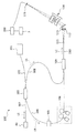
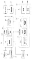
- the ophthalmologic apparatus 1 includes a fundus camera unit 2, an OCT unit 100, and an arithmetic control unit 200.
- the retinal camera unit 2 has almost the same optical system as a conventional retinal camera.
- the OCT unit 100 is provided with an optical system for acquiring an OCT image of the fundus.
- the arithmetic control unit 200 includes a computer that executes various arithmetic processes and control processes.
- the fundus camera unit 2 shown in FIG. 1 is provided with an optical system for obtaining a two-dimensional image (fundus image) representing the surface form of the fundus oculi Ef of the eye E to be examined.
- the fundus image includes an observation image and a captured image.
- the observation image is, for example, a monochrome moving image formed at a predetermined frame rate using near infrared light.
- the fundus camera unit 2 can obtain an observation image of the anterior segment Ea.
- the captured image may be, for example, a color image obtained by flashing visible light, or a monochrome still image using near infrared light or visible light as illumination light.
- the fundus camera unit 2 may be configured to be able to acquire images other than these, such as a fluorescein fluorescent image, an indocyanine green fluorescent image, a spontaneous fluorescent image, and the like.
- the fundus camera unit 2 is provided with a chin rest and a forehead for supporting the subject's face.
- the chin rest and the forehead support correspond to the support portion 440 shown in FIGS. 4A and 4B.
- reference numeral 410 denotes a drive system such as the optical system drive unit 2A and a base in which an arithmetic control circuit is stored.
- Reference numeral 420 denotes a housing provided on the base 410 and storing an optical system.
- Reference numeral 430 denotes a lens housing portion that is provided on the front surface of the housing 420 and accommodates the objective lens 22.
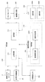
- the fundus camera unit 2 is provided with an illumination optical system 10 and a photographing optical system 30.
- the illumination optical system 10 irradiates the fundus oculi Ef with illumination light.
- the photographing optical system 30 guides the fundus reflection light of the illumination light to an imaging device (CCD image sensor (sometimes simply referred to as a CCD) 35, 38).
- the imaging optical system 30 guides the signal light from the OCT unit 100 to the fundus oculi Ef and guides the signal light passing through the fundus oculi Ef to the OCT unit 100.
- the observation light source 11 of the illumination optical system 10 is composed of, for example, a halogen lamp.
- the light (observation illumination light) output from the observation light source 11 is reflected by the reflection mirror 12 having a curved reflection surface, passes through the condensing lens 13, passes through the visible cut filter 14, and is converted into near infrared light. Become. Further, the observation illumination light is once converged in the vicinity of the photographing light source 15, reflected by the mirror 16, and passes through the relay lenses 17 and 18, the diaphragm 19 and the relay lens 20. Then, the observation illumination light is reflected at the peripheral portion (region around the hole portion) of the aperture mirror 21, passes through the dichroic mirror 46, and is refracted by the objective lens 22 to illuminate the fundus oculi Ef.
- An LED Light Emitting Diode
- the fundus reflection light of the observation illumination light is refracted by the objective lens 22, passes through the dichroic mirror 46, passes through the hole formed in the central region of the perforated mirror 21, passes through the dichroic mirror 55, and is a focusing lens. It is reflected by the mirror 32 via 31. Further, the fundus reflection light passes through the half mirror 39A, is reflected by the dichroic mirror 33, and forms an image on the light receiving surface of the CCD image sensor 35 by the condenser lens.
- the CCD image sensor 35 detects fundus reflected light at a predetermined frame rate, for example.
- On the display device 3 an image (observation image) based on fundus reflection light detected by the CCD image sensor 35 is displayed.
- an observation image is an example of a front image obtained by photographing the anterior segment Ea from the front of the subject.
- the photographing light source 15 is constituted by, for example, a xenon lamp.
- the light (imaging illumination light) output from the imaging light source 15 is applied to the fundus oculi Ef through the same path as the observation illumination light.
- the fundus reflection light of the imaging illumination light is guided to the dichroic mirror 33 through the same path as that of the observation illumination light, passes through the dichroic mirror 33, is reflected by the mirror 36, and is reflected by the condenser lens 37 of the CCD image sensor 38.
- An image is formed on the light receiving surface.
- On the display device 3 an image (captured image) based on fundus reflection light detected by the CCD image sensor 38 is displayed.
- the display device 3 that displays the observation image and the display device 3 that displays the captured image may be the same or different.
- an infrared captured image is displayed. It is also possible to use an LED as a photographing light source.
- the photographed image is an example of a front image obtained by photographing the anterior segment Ea from the front of the subject.
- the LCD (Liquid Crystal Display) 39 displays a fixation target and an eyesight measurement index.
- the fixation target is an index for fixing the eye E to be examined, and is used at the time of fundus photographing or OCT measurement.
- a part of the light output from the LCD 39 is reflected by the half mirror 39A, reflected by the mirror 32, passes through the focusing lens 31 and the dichroic mirror 55, passes through the hole of the perforated mirror 21, and reaches the dichroic.
- the light passes through the mirror 46, is refracted by the objective lens 22, and is projected onto the fundus oculi Ef.
- the projection direction of the fixation target with respect to the eye E that is, the fixation position of the eye E can be changed.
- the fixation position of the eye E for example, a position for acquiring an image centered on the macular portion of the fundus oculi Ef, or a position for acquiring an image centered on the optic disc as in the case of a conventional fundus camera And a position for acquiring an image centered on the fundus center between the macula and the optic disc. It is also possible to arbitrarily change the display position of the fixation target.
- the means for projecting the fixation target onto the eye E is not limited to this.
- the fundus camera unit 2 is provided with an alignment optical system 50 and a focus optical system 60 as in the conventional fundus camera.
- the alignment optical system 50 generates an index (alignment index) for performing alignment (alignment) of the apparatus optical system with respect to the eye E.
- the focus optical system 60 generates an index (split index) for focusing on the fundus oculi Ef.
- the light (alignment light) output from the LED 51 of the alignment optical system 50 is reflected by the dichroic mirror 55 via the apertures 52 and 53 and the relay lens 54, passes through the hole of the perforated mirror 21, and reaches the dichroic mirror 46. And is projected onto the cornea of the eye E by the objective lens 22.
- the corneal reflection light of the alignment light passes through the objective lens 22, the dichroic mirror 46 and the hole, part of which passes through the dichroic mirror 55, passes through the focusing lens 31, is reflected by the mirror 32, and is half mirror
- the light passes through 39A, is reflected by the dichroic mirror 33, and is projected onto the light receiving surface of the CCD image sensor 35 by the condenser lens.
- the light reception image (alignment index) by the CCD image sensor 35 is displayed on the display device 3 together with the observation image.
- the user performs alignment by performing the same operation as that of a conventional fundus camera. Further, the arithmetic control unit 200 may perform alignment by analyzing the position of the alignment index and moving the optical system (auto-alignment function).
- auto-alignment can be performed using an anterior segment camera 300 described later, it is not essential that auto-alignment using an alignment index is possible.
- the auto-alignment using the alignment index can be performed when the auto-alignment using the anterior segment camera 300 is not successful, or the auto-alignment using the anterior segment camera 300 and the alignment index are used. It is also possible to configure so that auto alignment can be used selectively.
- the reflecting surface of the reflecting rod 67 is obliquely provided on the optical path of the illumination optical system 10.
- the light (focus light) output from the LED 61 of the focus optical system 60 passes through the relay lens 62, is separated into two light beams by the split indicator plate 63, passes through the two-hole aperture 64, and is reflected by the mirror 65, The light is focused on the reflecting surface of the reflecting bar 67 by the condenser lens 66 and reflected. Further, the focus light passes through the relay lens 20, is reflected by the perforated mirror 21, passes through the dichroic mirror 46, is refracted by the objective lens 22, and is projected onto the fundus oculi Ef.
- the fundus reflection light of the focus light is detected by the CCD image sensor 35 through the same path as the corneal reflection light of the alignment light.
- a light reception image (split index) by the CCD image sensor 35 is displayed on the display device 3 together with the observation image.
- the arithmetic and control unit 200 analyzes the position of the split index and moves the focusing lens 31 and the focus optical system 60 to perform focusing as in the conventional case (autofocus function). Alternatively, focusing may be performed manually while visually checking the split indicator.
- the dichroic mirror 46 branches the optical path for OCT measurement from the optical path for fundus imaging.
- the dichroic mirror 46 reflects light in a wavelength band used for OCT measurement and transmits light for fundus photographing.
- a collimator lens unit 40, an optical path length changing unit 41, a galvano scanner 42, a focusing lens 43, a mirror 44, and a relay lens 45 are provided in this order from the OCT unit 100 side. It has been.
- the optical path length changing unit 41 is movable in the direction of the arrow shown in FIG. 1, and changes the optical path length of the optical path for OCT measurement. This change in the optical path length is used for correcting the optical path length according to the axial length of the eye E or adjusting the interference state.
- the optical path length changing unit 41 includes, for example, a corner cube and a mechanism for moving the corner cube.
- the galvano scanner 42 changes the traveling direction of light (signal light LS) passing through the optical path for OCT measurement. Thereby, the fundus oculi Ef can be scanned with the signal light LS.
- the galvano scanner 42 includes, for example, a galvano mirror that scans the signal light LS in the x direction, a galvano mirror that scans in the y direction, and a mechanism that drives these independently. Thereby, the signal light LS can be scanned in an arbitrary direction on the xy plane.
- the fundus camera unit 2 is provided with an anterior eye camera 300.
- the anterior segment camera 300 images the anterior segment Ea substantially simultaneously from different directions.
- two cameras are provided on the subject-side surface of the fundus camera unit 2 (see anterior eye cameras 300A and 300B shown in FIG. 4A).
- the anterior eye cameras 300A and 300B are provided at positions deviated from the optical path of the illumination optical system 10 and the optical path of the imaging optical system 30, respectively.
- the two anterior eye cameras 300A and 300B may be collectively represented by reference numeral 300.
- two anterior eye cameras 300A and 300B are provided, but the number of anterior eye cameras in the present invention is an arbitrary number of 2 or more. However, in consideration of the arithmetic processing described later, a configuration that can photograph the anterior segment substantially simultaneously from two different directions is sufficient.
- the anterior segment camera 300 is provided separately from the illumination optical system 10 and the imaging optical system 30, but at least the imaging optical system 30 can be used to perform similar anterior segment imaging. . That is, one of the two or more anterior segment cameras may be carried by a configuration including the imaging optical system 30.
- this embodiment should just be comprised so that imaging
- substantially simultaneously indicates that a photographing timing shift that allows negligible eye movement is allowed in photographing with two or more anterior segment cameras. Thereby, an image when the eye E is substantially at the same position (orientation) can be acquired by two or more anterior segment cameras.
- shooting with two or more anterior eye cameras may be moving image shooting or still image shooting
- the case of moving image shooting will be described in detail.
- the above-described substantially simultaneous anterior ocular shooting can be realized by controlling the shooting start timing to match or by controlling the frame rate and shooting timing of each frame.
- this can be realized by controlling to match the shooting timing.
- the OCT unit 100 is provided with an optical system for acquiring an OCT image of the fundus oculi Ef.
- This optical system has the same configuration as a conventional spectral domain type OCT apparatus. That is, this optical system divides low-coherence light into reference light and signal light, and generates interference light by causing interference between the signal light passing through the fundus oculi Ef and the reference light passing through the reference optical path. It is configured to detect spectral components. This detection result (detection signal) is sent to the arithmetic control unit 200.
- a wavelength swept light source is provided instead of a light source that outputs a low coherence light source, and an optical member that spectrally decomposes interference light is not provided.
- a known technique corresponding to the type of OCT can be arbitrarily applied.
- the light source unit 101 outputs a broadband low-coherence light L0.
- the low coherence light L0 includes, for example, a near-infrared wavelength band (about 800 nm to 900 nm) and has a temporal coherence length of about several tens of micrometers. Note that near-infrared light having a wavelength band invisible to the human eye, for example, a center wavelength of about 1040 to 1060 nm, may be used as the low-coherence light L0.
- the light source unit 101 includes a super luminescent diode (Super Luminescent Diode: SLD), an LED, and an optical output device such as an SOA (Semiconductor Optical Amplifier).
- SLD Super Luminescent Diode
- LED an LED
- SOA semiconductor Optical Amplifier
- the low coherence light L0 output from the light source unit 101 is guided to the fiber coupler 103 by the optical fiber 102, and is divided into the signal light LS and the reference light LR.
- the reference light LR is guided by the optical fiber 104 and reaches an optical attenuator (attenuator) 105.
- the optical attenuator 105 automatically adjusts the amount of the reference light LR guided to the optical fiber 104 under the control of the arithmetic control unit 200 using a known technique.
- the reference light LR whose light amount has been adjusted by the optical attenuator 105 is guided by the optical fiber 104 and reaches the polarization adjuster (polarization controller) 106.
- the polarization adjuster 106 is, for example, a device that adjusts the polarization state of the reference light LR guided in the optical fiber 104 by applying a stress from the outside to the optical fiber 104 in a loop shape.
- the configuration of the polarization adjuster 106 is not limited to this, and any known technique can be used.
- the reference light LR whose polarization state is adjusted by the polarization adjuster 106 reaches the fiber coupler 109.
- the signal light LS generated by the fiber coupler 103 is guided by the optical fiber 107 and converted into a parallel light beam by the collimator lens unit 40. Further, the signal light LS reaches the dichroic mirror 46 via the optical path length changing unit 41, the galvano scanner 42, the focusing lens 43, the mirror 44, and the relay lens 45. The signal light LS is reflected by the dichroic mirror 46, is refracted by the objective lens 22, and is applied to the fundus oculi Ef. The signal light LS is scattered (including reflection) at various depth positions of the fundus oculi Ef. The backscattered light of the signal light LS from the fundus oculi Ef travels in the same direction as the forward path in the reverse direction, is guided to the fiber coupler 103, and reaches the fiber coupler 109 via the optical fiber 108.
- the fiber coupler 109 causes the backscattered light of the signal light LS and the reference light LR that has passed through the optical fiber 104 to interfere with each other.
- the interference light LC generated thereby is guided by the optical fiber 110 and emitted from the emission end 111. Further, the interference light LC is converted into a parallel light beam by the collimator lens 112, dispersed (spectral decomposition) by the diffraction grating 113, condensed by the condenser lens 114, and projected onto the light receiving surface of the CCD image sensor 115.
- the diffraction grating 113 shown in FIG. 2 is a transmission type, other types of spectroscopic elements such as a reflection type diffraction grating may be used.
- the CCD image sensor 115 is a line sensor, for example, and detects each spectral component of the split interference light LC and converts it into electric charges.
- the CCD image sensor 115 accumulates this electric charge, generates a detection signal, and sends it to the arithmetic control unit 200.
- a Michelson type interferometer is used, but any type of interferometer such as a Mach-Zehnder type can be appropriately used.
- any type of interferometer such as a Mach-Zehnder type can be appropriately used.
- another form of image sensor for example, a CMOS (Complementary Metal Oxide Semiconductor) image sensor or the like can be used.
- CMOS Complementary Metal Oxide Semiconductor
- the configuration of the arithmetic control unit 200 will be described.
- the arithmetic control unit 200 analyzes the detection signal input from the CCD image sensor 115 and forms an OCT image of the fundus oculi Ef.
- the arithmetic processing for this is the same as that of a conventional spectral domain type OCT apparatus.
- the arithmetic control unit 200 controls each part of the fundus camera unit 2, the display device 3, and the OCT unit 100. For example, the arithmetic control unit 200 displays an OCT image of the fundus oculi Ef on the display device 3.
- the arithmetic control unit 200 controls the operation of the observation light source 11, the imaging light source 15 and the LEDs 51 and 61, the operation control of the LCD 39, the movement control of the focusing lenses 31 and 43, and the reflector 67. Movement control, movement control of the focus optical system 60, movement control of the optical path length changing unit 41, operation control of the galvano scanner 42, operation control of the anterior eye camera 300, and the like are performed.
- the arithmetic control unit 200 performs operation control of the light source unit 101, operation control of the optical attenuator 105, operation control of the polarization adjuster 106, operation control of the CCD image sensor 115, and the like.
- the arithmetic control unit 200 includes, for example, a microprocessor, a RAM, a ROM, a hard disk drive, a communication interface, and the like, as in a conventional computer.
- a computer program for controlling the ophthalmologic apparatus 1 is stored in a storage device such as a hard disk drive.
- the arithmetic control unit 200 may include various circuit boards, for example, a circuit board for forming an OCT image.
- the arithmetic control unit 200 may include an operation device (input device) such as a keyboard and a mouse, and a display device such as an LCD.
- the fundus camera unit 2, the display device 3, the OCT unit 100, and the calculation control unit 200 may be configured integrally (that is, in a single housing) or separated into two or more cases. It may be.
- Control system The configuration of the control system of the ophthalmologic apparatus 1 will be described with reference to FIG.
- the control system of the ophthalmologic apparatus 1 is configured around the control unit 210.
- the control unit 210 includes, for example, the aforementioned microprocessor, RAM, ROM, hard disk drive, communication interface, and the like.
- the control unit 210 includes a main control unit 211, a storage unit 212, an optical system position acquisition unit 213, and a movement information identification unit 214.
- the main control unit 211 performs the various operation controls described above.
- the movement control of the focusing lens 31 is to move the focusing lens 31 in the optical axis direction by controlling a focusing drive unit (not shown). Thereby, the focus position of the photographic optical system 30 is changed.
- the main control unit 211 can control the optical system driving unit 2A to move the optical system provided in the fundus camera unit 2 three-dimensionally.
- tracking refers to moving the apparatus optical system in accordance with the eye movement of the eye E. Tracking is performed, for example, at a later stage than alignment (in some cases, focusing is also performed in advance). Tracking is a function that maintains a suitable positional relationship in alignment (and focus) by causing the position of the apparatus optical system to follow the eye movement.
- optical system drive unit 2A of this embodiment moves an optical system mounted on the fundus camera unit 2, but the optical system mounted on the fundus camera unit 2 and the optical system mounted on the OCT unit 100. May be configured to be moved by the optical system driving unit 2A.
- the optical system drive unit 2A is an example of a “drive unit”.
- the anterior eye camera 300 of this embodiment is provided in the housing of the fundus camera unit 2, the anterior eye camera 300 can be moved by controlling the optical system driving part 2A. Further, it is possible to provide a photographing moving unit that can independently move two or more anterior eye camera 300.
- the imaging moving unit may include a drive mechanism (an actuator, a power transmission mechanism, etc.) provided for each anterior eye camera 300.
- the imaging moving unit is configured to move two or more anterior eye cameras 300 by transmitting power generated by a single actuator by a power transmission mechanism provided for each anterior eye camera 300. May be.
- the main control unit 211 performs a process of writing data to the storage unit 212 and a process of reading data from the storage unit 212.
- the storage unit 212 stores various data. Examples of the data stored in the storage unit 212 include OCT image image data, fundus image data, and examined eye information.
- the eye information includes information about the subject such as patient ID and name, and information about the eye such as left / right eye identification information.
- the storage unit 212 stores various programs and data for operating the ophthalmologic apparatus 1.
- Aberration information (not shown) is stored in the storage unit 212 in advance.
- information on distortion aberration generated in the captured image due to the influence of the optical system mounted on each anterior segment camera 300 is recorded.
- the optical system mounted on the anterior segment camera 300 includes an optical element that generates distortion, such as a lens.
- the aberration information can be said to be a parameter obtained by quantifying the distortion that these optical elements give to the photographed image.
- the operator prepares a predetermined reference point.
- the reference point is an imaging target used for detecting distortion.
- the operator performs multiple shootings while changing the relative position between the reference point and the anterior eye camera 300. Thereby, a plurality of captured images of the reference point captured from different directions are obtained.
- the operator generates aberration information of the anterior eye camera 300 by analyzing a plurality of acquired captured images with a computer.
- the computer that performs this analysis processing may be the image processing unit 230 or any other computer (an inspection computer before product shipment, a maintenance computer, etc.).
- the analysis process for generating aberration information includes, for example, the following steps: An extraction step of extracting an image region corresponding to the reference point from each captured image; A distribution state calculation step of calculating a distribution state (coordinates) of an image area corresponding to a reference point in each captured image; A distortion aberration calculating step of calculating a parameter representing distortion based on the obtained distribution state; A correction coefficient calculation step of calculating a coefficient for correcting distortion based on the obtained parameter.
- the parameters related to the distortion aberration given to the image by the optical system include principal point distance, principal point position (vertical direction, horizontal direction), lens distortion (radial direction, tangential direction), and the like.
- the aberration information is configured as information (for example, table information) in which the identification information of each anterior segment camera 300 is associated with the correction coefficient corresponding thereto.
- the aberration information generated in this way is stored in the storage unit 212 by the main control unit 211. Such generation of aberration information and correction of aberration based on the aberration information are called camera calibration.
- correspondence information 212a is stored in the storage unit 212 in advance.
- the movement direction and movement amount of the inspection optical system are associated with the displacement direction and displacement amount of the eye to be examined.
- the direction and amount of displacement of the eye to be examined indicate the displacement of the eye to be examined due to eye movement. Examples of eye movement include horizontal movement, vertical (vertical) movement, and rotational movement.
- the position of the inspection optical system is adjusted according to the state of the eye movement.
- the correspondence information 212a associates the state of eye movement (that is, the displacement direction and displacement amount of the eye to be examined) with the movement content (movement direction and movement amount) of the inspection optical system.
- the moving direction is a direction orthogonal to the optical axis of the inspection optical system. That is, the moving direction is an arbitrary direction in the xy plane shown in FIG.
- the correspondence information 212a is created, for example, by simulation.
- ray tracing can be performed while changing the displacement direction and amount of the model eye.
- the displacement direction is set equal to the displacement direction of the model eye.
- the amount of displacement is set by simulation.
- the optical distance between the position of the inspection light incident on the eye and the inspection position may change.
- the inspection light is incident on the eyeball from the vicinity of the top of the cornea and irradiated to the central part of the fundus, and when inspecting the peripheral part, The light enters the eyeball from the film and is irradiated to the periphery of the fundus.
- the incident position on the crystalline lens also affects the optical distance of the inspection light. Since the eyeball optical system is configured to be substantially rotationally symmetric with respect to the axis of the eyeball, the change in the optical distance is mainly affected by the amount of movement of the inspection optical system.
- a change in the optical distance corresponding to the movement amount of the inspection optical system can be obtained by simulation or the like, and can be used as the movement amount in the optical axis direction (z direction) of the inspection optical system.
- This movement amount is recorded in the correspondence information 212a as a correction amount for a predetermined working distance, for example.
- the working distance is a predetermined value called a working distance, and means a distance between the eye to be examined and the inspection optical system at the time of inspection using the inspection optical system.
- the displacement direction of the inspection optical system may include the rotation direction of the eye E, and the displacement amount may include the rotation amount of the eye E.
- the movement direction and the movement amount are associated with the rotation direction and the rotation amount. This correspondence is acquired by a simulation similar to the above, for example.
- the optical system position acquisition unit 213 acquires the current position of the inspection optical system mounted on the ophthalmologic apparatus 1.
- the inspection optical system is an optical system used to optically inspect the eye E.
- the inspection optical system in the ophthalmologic apparatus 1 (a combination machine of a fundus camera and an OCT apparatus) of this embodiment is an optical system for obtaining an image of the eye to be examined.
- the optical system position acquisition unit 213 receives, for example, information indicating the content of movement control of the optical system driving unit 2A by the main control unit 211, and acquires the current position of the inspection optical system moved by the optical system driving unit 2A. To do. A specific example of this process will be described.
- the main control unit 211 controls the optical system driving unit 2A at a predetermined timing (when the apparatus is activated, when patient information is input, etc.) to move the examination optical system to a predetermined initial position. Thereafter, each time the optical system driving unit 2A is controlled, the main control unit 211 records the control contents. Thereby, a history of control contents is obtained.
- the optical system position acquisition unit 213 acquires the control content up to the present with reference to this history, and obtains the current position of the inspection optical system based on the control content.
- the control content is transmitted to the optical system position acquisition unit 213, and each time the optical system position acquisition unit 213 receives the control content, the inspection optical system is transmitted.
- the current position may be obtained sequentially.
- a position sensor that detects the position of the inspection optical system may be provided in the optical system position acquisition unit 213.
- the main control unit 211 determines the acquired current position and the eye E to be examined obtained by the analysis unit 231 described later.
- the inspection optical system can be moved to the optical system driving unit 2A based on the three-dimensional position.
- the main control unit 211 recognizes the current position of the inspection optical system based on the acquisition result obtained by the optical system position acquisition unit 213, and recognizes the three-dimensional position of the eye E based on the analysis result obtained by the analysis unit 231.
- the main control unit 211 changes the position of the inspection optical system from the current position so that the position of the inspection optical system with respect to the three-dimensional position of the eye E has a predetermined positional relationship.
- This predetermined positional relationship is such that the positions in the x direction and the y direction coincide with each other and the distance in the z direction becomes a predetermined working distance.
- the analysis unit 231 acquires displacement information indicating a displacement direction and a displacement amount of the eye E to be examined by eye movement by analyzing a captured image acquired by the anterior eye camera 300.
- the movement information identification unit 214 identifies the movement direction and the movement amount corresponding to the displacement direction and the displacement amount indicated in the displacement information based on the correspondence information 212a. In this process, the movement direction and the movement amount associated with the displacement direction and the displacement amount indicated in the displacement information are searched from the correspondence relationship included in the correspondence information 212a.
- the image forming unit 220 forms tomographic image data of the fundus oculi Ef based on the detection signal from the CCD image sensor 115.
- This process includes processes such as noise removal (noise reduction), filter processing, FFT (Fast Fourier Transform), and the like, as in the conventional spectral domain type optical coherence tomography.
- the image forming unit 220 executes a known process corresponding to the type.
- the image forming unit 220 includes, for example, the circuit board described above. In this specification, “image data” and “image” based thereon may be identified.
- the image processing unit 230 performs various types of image processing and analysis processing on the image formed by the image forming unit 220. For example, the image processing unit 230 executes various correction processes such as image brightness correction and dispersion correction. The image processing unit 230 performs various types of image processing and analysis processing on the image (fundus image, anterior eye image, etc.) obtained by the fundus camera unit 2.
- the image processing unit 230 executes known image processing such as interpolation processing for interpolating pixels between tomographic images to form image data of a three-dimensional image of the fundus oculi Ef.
- image data of a three-dimensional image means image data in which pixel positions are defined by a three-dimensional coordinate system.
- image data of a three-dimensional image there is image data composed of voxels arranged three-dimensionally. This image data is called volume data or voxel data.
- the image processing unit 230 When displaying an image based on volume data, the image processing unit 230 performs a rendering process (such as volume rendering or MIP (Maximum Intensity Projection)) on the volume data, and views the image from a specific line-of-sight direction.
- Image data of a pseudo three-dimensional image is formed.
- the pseudo three-dimensional image is displayed on the display unit 240A.
- stack data of a plurality of tomographic images is image data of a three-dimensional image.
- the stack data is image data obtained by three-dimensionally arranging a plurality of tomographic images obtained along a plurality of scanning lines based on the positional relationship of the scanning lines. That is, stack data is image data obtained by expressing a plurality of tomographic images originally defined by individual two-dimensional coordinate systems by one three-dimensional coordinate system (that is, by embedding them in one three-dimensional space). is there.
- the image processing unit 230 is provided with an analysis unit 231.
- the analysis unit 231 obtains the three-dimensional position of the eye E by analyzing two captured images obtained substantially simultaneously by the anterior segment cameras 300A and 300B.
- the analysis unit 231 includes an image correction unit 2311, a feature point specification unit 2312, and a three-dimensional position calculation unit 2313.
- the analysis unit 231 obtains displacement information indicating the displacement direction and the displacement amount of the eye E to be examined by eye movement by analyzing the captured image obtained by the anterior eye camera 300.
- the analysis unit 231 includes a feature region specifying unit 2314, a shape information acquisition unit 2315, and a displacement information acquisition unit 2316.
- the image correction unit 2311 corrects the distortion of each captured image obtained by the anterior eye camera 300 based on the aberration information stored in the storage unit 212. This process is executed by, for example, a known image processing technique based on a correction coefficient for correcting distortion. Note that the aberration information and the image correction unit 2311 may not be provided when the distortion aberration given to the captured image by the optical system of the anterior segment camera 300 is sufficiently small.
- the feature point specifying unit 2312 analyzes each captured image (the distortion of which has been corrected by the image correcting unit 2311), thereby analyzing a position (feature point) in the captured image corresponding to a predetermined feature point of the anterior segment Ea. Is called).
- a predetermined feature point for example, the pupil center or corneal apex of the eye E is applied.
- the process of specifying the pupil center will be described.
- the feature point specifying unit 2312 specifies an image region (pupil region) corresponding to the pupil of the eye E based on the distribution of pixel values (such as luminance values) of the captured image.
- the pupil area can be specified by searching for the low brightness image area.
- the pupil region may be specified in consideration of the shape of the pupil. That is, the pupil region can be specified by searching for a substantially circular and low luminance image region.
- the feature point specifying unit 2312 specifies the center position of the specified pupil region. Since the pupil is substantially circular as described above, the contour of the pupil region can be specified, the center position of the approximate ellipse of this contour can be specified, and this can be used as the pupil center. Further, the center of gravity of the pupil region may be obtained, and the center of gravity position may be used as the center of the pupil.
- the position of the feature points can be specified based on the distribution of pixel values of the captured image in the same manner as described above.
- the three-dimensional position calculation unit 2313 performs the feature of the eye E based on the positions of the two or more anterior segment cameras 300 and the positions of the feature points in the two or more captured images specified by the feature point specifying unit 2312. The three-dimensional position of the point is calculated. This process will be described with reference to FIGS. 5A and 5B.
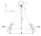
- FIG. 5A is a top view showing the positional relationship between the eye E and the anterior eye cameras 300A and 300B.
- FIG. 5B is a side view showing the positional relationship between the eye E and the anterior eye cameras 300A and 300B.
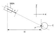
- the distance (baseline length) between the two anterior eye cameras 300A and 300B is represented by “B”.
- the distance (imaging distance) between the baselines of the two anterior eye cameras 300A and 300B and the characteristic part P of the eye E is represented by “H”.
- a distance (screen distance) between each anterior eye camera 300A and 300B and its screen plane is represented by “f”.
- the resolution of the captured image by the anterior segment cameras 300A and 300B is expressed by the following equation.
- ⁇ p represents pixel resolution.
- the three-dimensional position calculation unit 2313 is illustrated in FIGS. 5A and 5B with respect to the positions (known) of the two anterior eye cameras 300A and 300B and the position corresponding to the feature point P in the two captured images.
- the three-dimensional position of the feature point P that is, the three-dimensional position of the eye E to be examined is calculated.
- the three-dimensional position of the eye E calculated by the three-dimensional position calculation unit 2313 is sent to the control unit 210. Based on the calculation result of the three-dimensional position, the control unit 210 adjusts the optical axis of the inspection optical system to the axis of the eye E, and the distance of the inspection optical system with respect to the eye E is a predetermined operation.
- the optical system driving unit 2A is controlled so as to be a distance.
- the anterior eye camera 300 shoots a moving image of the anterior eye part Ea from different directions in parallel, for example, the following processes (1) and (2) are performed to test the movement of the eye E to be examined. It is possible to perform tracking of the optical system.
- the analysis unit 231 sequentially obtains the three-dimensional position of the eye E by sequentially analyzing two or more frames obtained substantially simultaneously in moving image shooting by the two or more anterior segment cameras 300. .
- the control unit 210 sequentially controls the optical system driving unit 2A based on the three-dimensional position of the eye E to be sequentially obtained by the analysis unit 231, thereby changing the position of the inspection optical system to the movement of the eye E. To follow.
- the feature region specifying unit 2314 specifies a feature region in the photographed image corresponding to the feature part of the anterior segment Ea by analyzing the photographed image acquired by the anterior segment camera 300. This process can be executed in the same manner as the feature point specifying unit 2312.
- Examples of the characteristic part of the anterior segment Ea include a pupil and an iris.
- a feature region corresponding to the pupil is referred to as a pupil region, and a feature region corresponding to the iris is referred to as an iris region.
- the feature region specifying unit 2314 may analyze the captured image that has been subjected to the above correction by the image correction unit 2311.
- the processing executed by the feature region specifying unit 2314 is a feature. Since it is included in the processing executed by the point specifying unit 2312, it is not necessary to provide the feature region specifying unit 2314. In that case, information on the feature region identified by the feature point identifying unit 2312 is input to the shape information acquiring unit 2315.
- shape information acquisition unit When inspecting the subject eye E in a state where eye movement is acting as in the case of inspecting the peripheral portion of the fundus oculi Ef, the shape of the characteristic region (pupil etc.) of the anterior segment Ea in the photographed image is It varies according to the displacement direction and displacement amount.
- the shape information acquisition unit 2315 acquires the shape of such a feature region.
- the shape information acquisition unit 2315 analyzes the feature region specified by the feature region specification unit 2314, thereby acquiring the shape information of the feature region. An example of this processing will be described.
- the shape information acquisition unit 2315 first obtains an approximate ellipse of the outline of the feature region (pupil region, iris region, etc.). This process can be executed in the same manner as the feature point specifying unit 2312, for example.
- the shape information acquisition unit 2315 calculates the major axis and minor axis of this approximate ellipse. This process is executed as follows, for example. First, the shape information acquisition unit 2315 obtains straight lines in various directions (tilts) passing through the center of the approximate ellipse, the first straight line having the longest line segment included in the approximate ellipse, and the shortest first line. 2 straight lines are identified. Furthermore, the shape information acquisition unit 2315 sets the length of the line segment in the first straight line as the major axis, and sets the length of the line segment in the second straight line as the minor axis.
- the length of the line segment is calculated as a distance (for example, the number of pixels) defined in the captured image, or as a distance obtained by converting this into a real space.
- the shape information of this embodiment includes information on the acquired major axis and minor axis. The shape information is not limited to this.
- the displacement information acquisition unit 2316 Based on the shape information acquired by the shape information acquisition unit 2315, the displacement information acquisition unit 2316 acquires displacement information indicating the displacement direction and the amount of displacement of the eye E due to eye movement. This process is executed with reference to, for example, information created in advance in which the information indicated by the shape information is associated with the displacement direction and the displacement amount. This information is called shape / displacement correspondence information.
- the shape / displacement correspondence information is created by, for example, obtaining the major axis and minor axis directions and the length ratio (ellipticity) corresponding to various directions of the eye to be examined or the model eye by simulation or actual measurement.
- a front image for example, an observation image
- This front image is obtained by photographing the anterior segment Ea in a state where the alignment index is projected. Therefore, the alignment index is depicted in this front image.
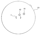
- FIGS. 6A and 6B An example of how the alignment index is drawn is shown in FIGS. 6A and 6B. 6A and 6B, the image of the eye E is omitted.
- the main control unit 211 superimposes and displays a bracket-shaped target image T indicating the alignment target position on the center position of the front image G1.
- the alignment index images A1 and A2 are drawn at positions away from the target image T. If the alignment in the z direction is shifted, the two alignment index images A1 and A2 are drawn at different positions. When all the alignments in the xyz direction are appropriate, the alignment index images A1 and A2 are drawn inside the target image T in a state of overlapping each other as shown in FIG. 6B.
- the displacement (displacement amount, displacement direction) of the alignment index images A1 and A2 with respect to the target image T indicates the alignment displacement (deviation amount, displacement direction) in the xy direction.
- the displacement (displacement amount, displacement direction) of the two alignment index images A1 and A2 indicates an alignment displacement (deviation amount, displacement direction) in the z direction.
- the analyzing unit 231 analyzes the front image G1 to obtain an alignment shift, and acquires an amount of movement of the optical system that cancels the shift. This process is executed as follows, for example. First, the analysis unit 231 specifies an image region corresponding to the alignment index images A1 and A2 based on the pixel information (luminance value and the like) of the front image G1. Next, the analysis unit 231 identifies the characteristic position (center, center of gravity, etc.) of each identified image region. Subsequently, the analysis unit 231 obtains the displacement of the feature position of each image region with respect to the center position of the target image T.
- the analysis unit 231 obtains an alignment deviation based on the obtained displacement, and obtains an amount of movement of the optical system that cancels the alignment deviation.
- the analysis unit 231 previously stores information that associates the displacement of the alignment index image defined in the coordinate system of the front image with the alignment shift defined in the coordinate system of the real space.
- the alignment shift can be obtained by referring to the information.
- the image processing unit 230 that functions as described above includes, for example, the aforementioned microprocessor, RAM, ROM, hard disk drive, circuit board, and the like.
- a storage device such as a hard disk drive, a computer program for causing the microprocessor to execute the above functions is stored in advance.
- the user interface 240 includes a display unit 240A and an operation unit 240B.
- the display unit 240A includes the display device of the arithmetic control unit 200 and the display device 3 described above.
- the operation unit 240B includes the operation device of the arithmetic control unit 200 described above.
- the operation unit 240B may include various buttons and keys provided on the housing of the ophthalmologic apparatus 1 or outside.
- the operation unit 240B may include a joystick, an operation panel, or the like provided on the housing.
- the display unit 240 ⁇ / b> A may include various display devices such as a touch panel provided on the housing of the fundus camera unit 2.
- the display unit 240A and the operation unit 240B do not need to be configured as individual devices.
- a device in which a display function and an operation function are integrated such as a touch panel
- the operation unit 240B includes the touch panel and a computer program.
- the operation content for the operation unit 240B is input to the control unit 210 as an electrical signal. Further, operations and information input may be performed using a graphical user interface (GUI) displayed on the display unit 240A and the operation unit 240B.
- GUI graphical user interface
- a first operation example will be described with reference to FIG.
- the second alignment for moving the inspection optical system based on the displacement information of the eye E.
- processing is executed.
- the inspection optical system is moved according to the spatial position of the eye E
- the inspection optical system is moved according to the state of eye movement of the eye E.
- Patient information includes patient ID, patient name, and the like.
- the examination type items include the examination site (fundus center, fundus periphery, optic disc, macular, etc.), eye to be examined (left eye, right eye, both eyes), image capturing pattern (fundus image only, OCT image only, Both), OCT scan patterns (line scan, cross scan, radial scan, circle scan, three-dimensional scan, etc.).
- the peripheral portion of the fundus oculi Ef is selected as the examination site. Note that, for example, when the center of the fundus is selected as the examination site, when the second alignment process is not necessary or when the necessity is low, only the first alignment process is performed. It is possible to perform control so as to.
- the start instruction may be automatically issued by the control unit 210 in response to the selection of the examination type shown in step 2, or may be manually given by the user using the operation unit 240B.
- the control unit 210 starts imaging of the anterior segment Ea by the anterior segment cameras 300A and 300B.
- This shooting is moving image shooting in which the anterior segment Ea is a shooting target.
- Each anterior eye camera 300A and 300B shoots a moving image at a predetermined frame rate.
- the imaging timings of the anterior eye cameras 300A and 300B may be synchronized by the control unit 210.
- Each anterior eye camera 300A and 300B sequentially sends the acquired frames to the control unit 210 in real time.
- the controller 210 associates the frames obtained by both anterior eye cameras 300A and 300B according to the photographing timing.
- control unit 210 associates frames acquired substantially simultaneously by both anterior eye cameras 300A and 300B. This association is executed, for example, based on the above-described synchronization control or based on the input timing of frames from the anterior eye cameras 300A and 300B.
- the control unit 210 sends a pair of associated frames to the analysis unit 231.
- the image correction unit 2311 corrects the distortion of each frame sent from the control unit 210 based on the aberration information stored in the storage unit 212. This correction processing is executed as described above. The pair of frames whose distortion has been corrected is sent to the feature point specifying unit 2312.
- the feature point specifying unit 2312 analyzes each frame sent from the image correction unit 2311 to execute processing for specifying a position in the frame corresponding to the feature point (pupil center) of the anterior segment Ea. To do.
- the feature point identification process is executed again after the anterior eye cameras 300A and 300B are moved in the direction away from the support unit 440 and / or the outside of the support unit 440. It is possible to control.
- the distance between the anterior eye cameras 300A and 300B and the subject (eye E) increases, and the face of the subject It is possible to shoot a wider range. Therefore, the possibility that the eye E is arranged in a suitable imageable range by the anterior eye cameras 300A and 300B increases.
- the anterior eye cameras 300A and 300B move in the direction of the subject's ear, and the eye to be examined is in a suitable photographing range.
- the possibility that E is arranged increases.
- the possibility that the eye E to be examined is arranged in a suitable photographing range is further increased. It should be noted that when this routine is repeated a predetermined number of times, control can be performed so as to shift to manual alignment.
- the movement control of the anterior segment cameras 300A and 300B similar to the above can be performed.
- the three-dimensional position calculation unit 2313 determines the feature point (pupil center) of the eye E based on the positions of the anterior eye cameras 300A and 300B and the position of the feature point specified for the pair of frames by the feature point specification unit 2312. ) Is calculated. This process is executed as described above.
- control unit 210 Based on the three-dimensional position of the center of the pupil calculated in step 6, the control unit 210 matches the optical axis of the inspection optical system with the axis of the eye E, and the inspection optical system for the eye E is inspected.
- the optical system driving unit 2A is controlled so that the distance becomes a predetermined working distance.
- the control unit 210 determines whether the position of the inspection optical system has converged. This determination process is performed using, for example, an alignment index.
- the observation state of the alignment index changes according to the alignment state. Specifically, in a state where the alignment is suitable, the two images of the alignment index are observed at substantially the same position, and the positions of the two images are observed apart as the alignment state deteriorates.
- the control unit 210 obtains a distance between two images taken by the CCD image sensor 35 and determines whether this distance is equal to or smaller than a predetermined threshold value. If it is determined that this distance is equal to or smaller than the predetermined threshold (S8: YES), it is determined that the position of the inspection optical system has converged, and the first alignment process ends, and the second alignment shown in step 9 is performed. Transition to processing.
- Steps 5 to 8 are repeated until, for example, “NO” is determined a predetermined number of times in step 8.
- the control unit 210 outputs, for example, predetermined warning information.
- step 8 When it is determined in step 8 that the position of the inspection optical system has converged (S8: YES), the control unit 210 ends the first alignment process and starts the second alignment process.
- the feature region specifying unit 2314 analyzes each frame sent from the image correction unit 2311 to specify a feature region (pupil region) in the frame corresponding to the feature part (pupil) of the anterior segment Ea.
- the shape information acquisition unit 2315 acquires the shape information of the feature region (pupil region) by analyzing the feature region identified in Step 10. This process is executed, for example, by obtaining the major axis and minor axis of the approximate ellipse of the pupil region.
- the displacement information acquisition unit 2316 acquires displacement information indicating the displacement direction and the amount of displacement of the eye E by eye movement based on the shape information acquired in step 11.
- the movement information identification unit 214 identifies the movement direction and the movement amount corresponding to the displacement direction and the displacement amount indicated in the displacement information acquired in Step 12 by referring to the correspondence information 212a. Then, the control unit 210 moves the inspection optical system in the movement direction by the movement direction by controlling the optical system driving unit 2A. This inspection optical system is moved in the xy plane. This completes the second alignment process.
- control unit 210 can also move the inspection optical system in the z direction by controlling the optical system driving unit 2A based on the movement amount. This movement of the inspection optical system in the z direction corresponds to the third alignment process.
- a second operation example will be described with reference to FIG.
- the success or failure of the first alignment process is determined.
- the first alignment process is unsuccessful, alignment using an alignment index is performed, and then the second alignment process is performed. is there.
- Steps 21 to 27 are executed in the same manner as steps 1 to 7 in the first operation example.
- the process proceeds to the alignment in step 29.
- the determination that the first alignment process has failed is made, for example, when the convergence determination process is repeated a predetermined number of times.
- step 28 If it is determined in step 28 that the first alignment process has failed, the controller 210 causes the above-described alignment to be executed.
- This alignment may be automatic alignment or manual alignment. Alternatively, first, auto alignment may be executed, and in response to the failure, manual alignment may be performed.
- Steps 31 to 37 are executed in the same manner as steps 9 to 15 in the first operation example. Thus, this operation example ends.
- the ophthalmologic apparatus 1 includes an examination optical system, an optical system drive unit 2A (drive unit), an anterior eye camera 300 (two or more imaging units), an analysis unit 231 and a control unit 210.
- the inspection optical system is an optical system for inspecting the eye E.
- the optical system driving unit 2A moves the inspection optical system.
- the anterior segment camera 300 images the anterior segment Ea of the eye E from substantially different directions at the same time.
- the analysis unit 231 obtains the three-dimensional position of the eye E by analyzing the captured image acquired by the anterior eye camera 300. Further, the analysis unit 231 obtains displacement information indicating the displacement direction and the displacement amount of the eye E to be examined by eye movement by analyzing the captured image obtained by the anterior eye camera 300.
- the control unit 210 controls the optical system driving unit 2 based on the three-dimensional position of the eye E acquired by the analysis unit 231 to move the inspection optical system (first alignment process). Further, the control unit 210 controls the optical system driving unit 2A based on the displacement information acquired by the analysis unit 231 to move the inspection optical system (second alignment process).
- the inspection optical system is aligned according to the spatial arrangement state of the eye E by the first alignment process, and the eye movement of the eye E by the second alignment process.
- the inspection optical system can be aligned according to the state. Therefore, precise positioning according to the state of the eye E can be performed, and the examination can be suitably performed.
- the displacement direction includes, for example, at least one of a horizontal direction, a vertical direction, and a rotation direction.
- the analysis unit 231 includes a feature region specifying unit 2314, a shape information acquisition unit 2315, and a displacement information acquisition unit 2316.
- the feature region specifying unit 2314 specifies a feature region in the photographed image corresponding to the feature part of the anterior segment Ea by analyzing the photographed image acquired by the anterior segment camera 300.
- the shape information acquisition unit 2315 acquires the shape information of the feature region by analyzing the specified feature region.
- the displacement information acquisition unit 2316 acquires displacement information indicating the displacement direction and the amount of displacement of the eye E by eye movement.
- the process for obtaining the displacement information is executed as follows, for example.
- the feature region specifying unit 2314 specifies the pupil region corresponding to the pupil or the iris region corresponding to the iris as the feature region.
- the shape information acquisition unit 2315 obtains an approximate ellipse of the outline of the specified pupil region or iris region, and acquires shape information by calculating the major axis and minor axis of the approximate ellipse.
- the displacement information acquisition unit 2316 obtains the displacement direction based on the major axis or minor axis direction indicated in the shape information, and obtains the displacement amount based on the ratio (ellipticity) between the major axis and the minor axis. This technique can be applied to any characteristic part of the anterior segment Ea having a shape that can be approximated to an ellipse.
- the analysis unit 231 includes a feature point specifying unit 2312 and a three-dimensional position calculation unit 2313.
- the feature point identifying unit 2312 identifies the position in the captured image corresponding to the feature point of the anterior segment Ea by analyzing two captured images acquired substantially simultaneously by the anterior segment cameras 300A and 300B. To do.
- the three-dimensional position calculation unit 2313 calculates the three-dimensional position of the feature point in the real space based on the position corresponding to the identified feature point and the positions of the anterior eye camera 300A and 300B. The calculation result of the three-dimensional position of the feature point is applied as the three-dimensional position of the eye E.
- a plurality of alignment processes are executed in this embodiment.
- the plurality of alignment processes are executed in the following order, for example.
- the control unit 210 can perform control so as to execute the second alignment process after executing the first alignment process. In this way, by performing the first alignment process and the second alignment process continuously, precise alignment can be performed quickly.
- the control unit 210 can perform control so as to execute alignment in response to the failure of the first alignment process, and then execute the second alignment process.
- the ophthalmologic apparatus 1 includes an alignment optical system 50 and a front image acquisition unit.
- the alignment optical system 50 projects the alignment index onto the anterior segment Ea.
- the front image acquisition unit acquires the front image of the anterior segment Ea by imaging the eye E with the alignment index projected thereon, and the illumination optical system 10 and the imaging optical system 30 correspond to this.
- the analysis unit 231 acquires the displacement of the inspection optical system with respect to the eye E by analyzing the acquired front image.
- the controller 210 determines whether the first alignment process is successful.
- the control unit 210 causes the second alignment process to be executed after executing the automatic alignment and / or the manual alignment. According to this example, even if the first alignment process fails, the spatial alignment of the inspection optical system with respect to the eye E is performed by alignment, and then the second alignment process is performed. It is possible.
- the success or failure of the first alignment process is influenced by the height of the nose, the degree of eye depression, and further by mascara and eye shadow.
- the control unit 210 includes a storage unit 212 (first storage unit) and a movement information specifying unit 214 (first movement information specifying unit).
- correspondence information 212a first correspondence information
- the movement information specifying unit 214 specifies the movement direction and the movement amount corresponding to the displacement direction and the displacement amount shown in the displacement information acquired by the analysis unit 231 based on the correspondence information 212a.
- the control unit 210 controls the optical system driving unit 2A so as to move the inspection optical system by the amount of movement in the movement direction specified by the movement information specifying unit 214.
- the moving direction in the second alignment process is, for example, a direction orthogonal to the optical axis of the inspection optical system (that is, an arbitrary direction in the xy plane).
- the control unit 210 can move the inspection optical system in the direction of the optical axis of the inspection optical system (that is, the z direction) based on the amount of movement of the inspection optical system in the second alignment process ( Third alignment process). This third alignment process is to compensate for the shift in working distance due to the second alignment process.
- the matching process is executed.
- This second alignment process is performed by analyzing captured images acquired by two or more imaging units.
- the second alignment process is executed based on the projection position of the fixation target.
- the same reference numerals are used for the same components as those in the first embodiment.
- the ophthalmologic apparatus 1 of this embodiment has a hardware configuration similar to that of the first embodiment, for example (see FIGS. 1 and 2).
- a configuration example of a control system of the ophthalmologic apparatus 1 of this embodiment is shown in FIG.
- the main difference from the control system of the first embodiment shown in FIG. 3 is that the feature region specifying unit 2314, the shape information acquiring unit 2315, and the displacement information acquiring unit 2316 are not provided. That is, the analysis unit 231 of this embodiment does not acquire displacement information used for the second alignment process.
- parts different from the first embodiment will be mainly described.
- the fixation optical system includes a fixation target presenting unit (LCD 39) for presenting a fixation target and a fixation target projection optical system for projecting the presented fixation target onto the eye E.
- the fixation target projection optical system is configured by an optical element that forms an optical path between the LCD 39 and the eye E.
- the fixation target projection optical system of this example includes a half mirror 39A, a mirror 32, a focusing lens 31, an objective lens 22, and the like.
- the control unit 210 displays a fixation target at the position of the LCD 39 corresponding to the examination site designated by the user, for example.
- the examination site and the display position of the fixation target are associated in advance.
- the display position of the fixation target can be arbitrarily changed using the operation unit 240B.
- correspondence information 212a as second correspondence information is stored in advance.
- the correspondence information 212a of this embodiment associates the movement direction and movement amount of the inspection optical system with the projection position of the fixation target.
- the projection position of the fixation target corresponds to the fixation position (fixation direction) or the inspection position of the eye to be examined.
- Correspondence information 212a is created based on the results of simulation and actual measurement, as in the first embodiment.
- the correspondence information 212a is created only when the eye movement is sufficiently applied, for example, when examining the fundus periphery.
- the correspondence information 212a may be associated with a movement direction and a movement amount for each of a plurality of fixation target display positions on the LCD 39.
- the plurality of display positions may be all positions at which the fixation target can be displayed on the LCD 39, or may be a part of the positions (for example, the fixation position is separated from the fundus center by a predetermined distance or more). Only if you have).
- the movement information specifying unit 214 of this embodiment uses the movement direction and movement amount of the inspection optical system corresponding to the projection position as correspondence information 212a. Identify based on.
- a first operation example will be described with reference to FIG.
- the second alignment for moving the inspection optical system based on the projection position of the fixation target.
- a case where processing is executed will be described.
- the inspection optical system is moved in accordance with the spatial position of the eye E, and in the second alignment process, the inspection optical system is in alignment with the fixation position for inducing eye movement of the eye E. Move the optical system.
- Steps 41 to 49 are executed in the same manner as steps 1 to 9 in the first operation example. That is, the first alignment process and the transition process from the first alignment process to the second alignment process are the same as in the first embodiment.
- the inspection position that is, the fixation position
- the control unit 210 controls the LCD 39 to display a fixation target at a display position corresponding to the selected fixation position.
- the movement information identification unit 214 refers to the correspondence information 212a and identifies the movement direction and movement amount corresponding to the fixation target projection position selected by the fixation optical system selected in Step 42.
- the control unit 210 moves the inspection optical system by controlling the optical system driving unit 2A based on the movement direction and the movement amount specified in step 50.
- Steps 52 and 53 are executed in the same manner as Steps 14 and 15 in the first operation example. Thus, this operation example ends.
- a second operation example will be described with reference to FIG.
- the success or failure of the first alignment process is determined.
- the first alignment process is unsuccessful, alignment using an alignment index is performed, and then the second alignment process is performed. is there.
- Steps 61 to 67 are executed in the same manner as steps 41 to 47 in the first operation example.
- step 67 the controller 210 performs a convergence determination process similar to step 8 of the first alignment process. If it is determined that convergence has occurred, that is, if it is determined that the first alignment process has been successful (S68: YES), the process proceeds to the second alignment process shown in step 71.
- the process proceeds to the alignment in step 69.
- the determination that the first alignment process has failed is made, for example, when the convergence determination process is repeated a predetermined number of times.
- step 68 If it is determined in step 68 that the first alignment process has failed, the control unit 210 causes the same alignment as in the first embodiment to be executed. Upon completion of the alignment, the control unit 210 proceeds to the second alignment process shown in step 71.
- Steps 71 to 75 are executed in the same manner as Steps 49 to 53 in the first operation example. Thus, this operation example ends.
- the ophthalmologic apparatus 1 includes an examination optical system, an optical system drive unit 2A (drive unit), a fixation optical system, an anterior eye camera 300 (two or more imaging units), an analysis unit 231, and a control unit 210. And have.
- the inspection optical system is an optical system for inspecting the eye E.
- the optical system driving unit 2A moves the inspection optical system.
- the fixation optical system projects a fixation target for visual line guidance onto the eye to be examined.
- the anterior segment camera 300 images the anterior segment Ea of the eye E from substantially different directions at the same time.
- the analysis unit 231 acquires the three-dimensional position of the eye E by analyzing the captured image acquired by the anterior eye camera 300.
- the control unit 210 performs a process of changing the projection position of the fixation target by controlling the fixation optical system.
- control unit 210 controls the optical system driving unit 2A based on the three-dimensional position of the eye E acquired by the analysis unit 231 to move the inspection optical system (first alignment process). Further, the control unit 210 moves the inspection optical system by controlling the optical system driving unit 2A based on the projection position of the fixation target (second alignment process).
- the inspection optical system is aligned according to the spatial arrangement state of the eye E by the first alignment process, and the eye movement of the eye E by the second alignment process.
- the optical system for inspection can be aligned in accordance with the fixation position that leads to a predetermined state. Therefore, precise positioning according to the state of the eye E can be performed, and the examination can be suitably performed.
- the control unit 210 includes a storage unit 212 (second storage unit) and a movement information specifying unit 214 (second movement information specifying unit).
- the storage unit 212 correspondence information 212a in which the movement direction and movement amount of the inspection optical system are associated with the projection position of the fixation target is stored in advance.
- the movement information specifying unit 214 specifies the movement direction and the movement amount corresponding to the projection position of the fixation target by the fixation optical system based on the correspondence information 212a.
- the control unit 210 performs the second alignment process based on the specified moving direction and moving amount.
- the fixation optical system includes an LCD 39 (fixation target presenting unit) and a fixation target projection optical system.
- the LCD 39 can present fixation targets at a plurality of positions.
- the fixation target projection optical system projects the presented fixation target onto the eye E.
- the movement direction and the movement amount of the inspection optical system are associated with each of the plurality of positions.
- the control unit 210 controls the LCD 39 to present a fixation target at any of the plurality of positions.
- the movement information identification unit 214 identifies the movement direction and the movement amount corresponding to the position where the fixation target is presented by the control unit 210 based on the correspondence information 212a.
- a plurality of alignment processes are executed in this embodiment.
- the plurality of alignment processes are executed in the following order, for example.
- the control unit 210 can perform control so as to execute the second alignment process after executing the first alignment process. In this way, by performing the first alignment process and the second alignment process continuously, precise alignment can be performed quickly.
- the control unit 210 can perform control so as to execute alignment in response to the failure of the first alignment process, and then execute the second alignment process.
- the ophthalmologic apparatus 1 includes an alignment optical system 50 and a front image acquisition unit.
- the alignment optical system 50 projects the alignment index onto the anterior segment Ea.
- the front image acquisition unit acquires the front image of the anterior segment Ea by imaging the eye E with the alignment index projected thereon, and the illumination optical system 10 and the imaging optical system 30 correspond to this.
- the analysis unit 231 acquires the displacement of the inspection optical system with respect to the eye E by analyzing the acquired front image.
- the controller 210 determines whether the first alignment process is successful.
- control unit 210 causes the second alignment process to be executed after executing the automatic alignment and / or the manual alignment. According to this example, even if the first alignment process fails, the spatial alignment of the inspection optical system with respect to the eye E is performed by alignment, and then the second alignment process is performed. It is possible.
- the moving direction of the inspection optical system in the second alignment process may be a direction orthogonal to the optical axis of the inspection optical system (that is, the xy direction).
- the control unit 210 can move the inspection optical system in the direction of the optical axis of the inspection optical system (that is, the z direction) based on the amount of movement of the inspection optical system in the second alignment process.
- Yes third alignment process. This third alignment process is to compensate for the shift in working distance due to the second alignment process.
- a feature point specifying unit 2312 and a three-dimensional position calculating unit 2313 similar to those in the first embodiment may be provided. Is possible.
- the ophthalmologic apparatus 1 of this embodiment has a hardware configuration similar to that of the first embodiment, for example (see FIGS. 1 and 2).
- An example of the configuration of the control system of the ophthalmologic apparatus 1 of this embodiment is shown in FIG. In this example, a configuration that can switch between an operation mode for a normal pupil eye having a general pupil diameter and an operation mode for a small pupil eye will be described.
- the operation mode information 212b is stored in the storage unit 212 in advance.
- various control contents are associated with pupil information indicating the state of the pupil.
- Pupil information includes pupil size (pupil diameter, etc.) and pupil shape.
- the control contents include fixation light intensity, observation light intensity, photographing light intensity, aperture, position of the inspection optical system, and the like.
- the fixation light intensity indicates the intensity of the projected light flux of the fixation target with respect to the eye E.
- the fixation light intensity is controlled by controlling the light emission intensity of the LCD 39, for example.
- the observation light intensity indicates the intensity of the observation illumination light.
- the observation light intensity is performed by controlling the emission intensity of the observation light source 11, for example.
- the photographing light intensity indicates the intensity of photographing illumination light.
- the photographing light intensity is controlled by controlling the output intensity of the photographing light source 15.
- the diaphragm control is, for example, switching control between a diaphragm for a normal pupil eye and a diaphragm for a small pupil eye.
- This diaphragm control includes control for selectively applying two diaphragms having different aperture sizes and control of a diaphragm capable of changing the aperture size.
- the stop to be controlled is, for example, the stop 19 of the illumination optical system 10 shown in FIG.
- the position of the inspection optical system is shifted in the case of a small pupil eye. Note that the shift amount can be changed according to the pupil size.
- FIG. 1 An example of the operation mode information 212a is shown in FIG.
- this operation mode information 212b as control contents corresponding to the normal mode applied to the normal pupil eye, fixation light intensity “a1”, observation light intensity “b1”, photographing light intensity “c1”, aperture “I”
- the optical system position “no shift” is associated.
- fixation light intensity “a2”, observation light intensity “b2”, photographing light intensity “c2”, aperture “III” optical system position “With shift” is associated.
- the fixation light intensity, the observation light intensity, and the photographing light intensity are defined by the value of the light intensity or an amount equivalent to the value (voltage value, current value, charge amount, etc.).
- the diaphragms “I” and “II” indicate identification information given to the two diaphragms. It is also possible to apply a shift amount instead of the optical system position “with shift”.
- the analysis unit 231 includes an image correction unit 2311, a pupil region specifying unit 2317, and a pupil information acquisition unit 2318.
- the image correction unit 2311 performs the same process as in the first embodiment.
- the pupil region specifying unit 2317 performs processing similar to the pupil region specifying processing (feature point specifying unit 2312) described in the first embodiment.
- the pupil information acquisition unit 2318 analyzes the pupil region specified by the pupil region specification unit 2317 and acquires the pupil size and the pupil shape. The acquisition of the pupil size is performed, for example, in the same manner as the processing in which the shape information acquisition unit 2315 of the second embodiment obtains the major axis of the approximate ellipse of the contour of the pupil region.
- the acquisition of the pupil shape is performed in the same manner as the processing for obtaining the ellipticity of the approximate ellipse of the outline of the pupil region, for example, by the shape information acquisition unit 2315.
- the analysis unit 231 performs a process of obtaining a three-dimensional position of the eye E by analyzing the captured image acquired by the anterior eye camera 300, as in the first embodiment.
- the control unit 210 executes alignment processing for controlling the optical system driving unit 2A based on the three-dimensional position of the eye E acquired by the analysis unit 231 to move the inspection optical system.
- the control unit 210 executes an optical system control process for controlling the optical system based on the pupil information acquired by the analysis unit 231. Examples of the control target of this optical system include the above-described fixation light intensity, observation light intensity, photographing light intensity, stop, and position of the inspection optical system.
- Steps 81 to 88 are executed in the same manner as Steps 1 to 8 in the first operation example.
- the alignment process the first alignment process of the first embodiment
- the transition to the subsequent process are the same as in the first embodiment.
- the analysis unit 231 acquires the pupil information of the eye E by performing, for example, the above process.
- the pupil information includes the pupil size and the pupil shape.
- the control unit 210 selects the normal mode or the small pupil mode based on the pupil information acquired in step 90. For example, this process compares the pupil size acquired in step 90 with a preset threshold value, selects the normal mode when the pupil size exceeds the threshold value, and reduces the pupil size when the pupil size is equal to or smaller than the threshold value. This is done by selecting the pupil mode.
- the control unit 210 acquires the control content corresponding to the operation mode selected in step 91 from the operation mode information 212b. Then, each of the fixation light intensity, the observation light intensity, the photographing light intensity, the stop, and the optical system position is controlled based on the acquired control content.
- Step 93 and step 94 are executed in the same manner as step 14 and step 15 of the first operation example. Thus, this operation example ends.
- the ophthalmologic apparatus 1 includes an optical system, an optical system drive unit 2A (drive unit), an anterior eye camera 300 (two or more imaging units), an analysis unit 231, and a control unit 210.
- the optical system includes an inspection optical system for inspecting the eye E.
- the optical system driving unit 2A moves the inspection optical system.
- the anterior segment camera 300 images the anterior segment Ea of the eye E from substantially different directions at the same time.
- the analysis unit 231 obtains the three-dimensional position of the eye E by analyzing the captured image acquired by the anterior eye camera 300.
- the analysis unit 231 acquires pupil information indicating the state of the pupil of the eye E by analyzing the captured image acquired by the anterior segment camera 300.
- the control unit 210 controls the optical system driving unit 2A based on the three-dimensional position of the eye E acquired by the analysis unit 231 to move the inspection optical system (positioning process).
- the control unit 210 controls the optical system based on the pupil information acquired by the analysis unit 231 (optical system control process).
- the alignment of the examination optical system is performed according to the spatial arrangement state of the eye E by the alignment process, and the state of the pupil of the eye E is determined by the optical system control process.
- the optical system can be controlled. Therefore, precise alignment and control according to the state of the eye E can be performed, and the examination can be suitably performed.
- the operation mode can be automatically changed according to the state of the pupil. Further, by analyzing a plurality of captured images acquired from different directions by the anterior eye camera 300, the state of the pupil of the eye E can be acquired with high accuracy and high accuracy.
- Optical system control processing includes, for example, control of one or more of fixation light intensity, observation light intensity, photographing light intensity, aperture, and optical system position.
- the optical system includes a fixation optical system that projects a fixation target for visual line guidance onto the eye to be examined.
- the analysis unit 231 acquires the pupil size as pupil information.
- the controller 210 controls the fixation optical system based on the acquired pupil size to change the intensity of the projected light flux of the fixation target.
- the optical system is disposed coaxially with the inspection optical system, and is disposed coaxially with the illumination optical system 10 (first illumination optical system) that irradiates the observation eye E with observation illumination light (continuous light) and the inspection optical system. And a photographing optical system 30 (first photographing optical system) for photographing a moving image of the eye E to which the observation illumination light is irradiated.
- the illumination optical system 10 and the imaging optical system 30 are included in the inspection optical system.
- the analysis unit 231 acquires the pupil size as pupil information.
- the control unit 210 changes the intensity of the observation illumination light by controlling the illumination optical system 10 based on the acquired pupil size.
- the optical system is disposed coaxially with the inspection optical system, and is disposed coaxially with the illumination optical system 10 (second illumination optical system) for irradiating the eye E with photographing illumination light (flash light) and the inspection optical system.
- a photographing optical system 30 (second photographing optical system) for photographing the eye E in synchronization with the irradiation of the photographing illumination light.
- the illumination optical system 10 and the imaging optical system 30 are included in the inspection optical system.
- the analysis unit 231 acquires the pupil size as pupil information.
- the controller 210 controls the illumination optical system 10 based on the acquired pupil size to change the intensity of the imaging illumination light.
- the optical system includes an illumination optical system 10 (third illumination optical system) that is arranged coaxially with the inspection optical system, includes two or more diaphragms (diaphragm 19) having different aperture sizes, and irradiates the eye E with illumination light. And an imaging optical system 30 (third imaging optical system) which is arranged coaxially with the inspection optical system and images the eye E to which the illumination light is irradiated.
- the illumination optical system 10 and the imaging optical system 30 are included in the inspection optical system.
- the analysis unit 231 acquires the pupil size as pupil information.
- the controller 210 selectively places the two or more stops in the optical path of the illumination optical system 10 based on the acquired pupil size.
- the analysis unit 231 acquires a pupil shape as pupil information.
- the control unit 210 controls the drive unit based on the acquired pupil shape to move the examination optical system. This movement control may include a process according to another embodiment.
- the ophthalmologic apparatus 1 of this embodiment has a hardware configuration similar to that of the first embodiment, for example (see FIGS. 1 and 2).
- a configuration example of the control system of the ophthalmologic apparatus 1 of this embodiment is shown in FIG.
- the analysis unit 231 includes an image correction unit 2311 and a blink determination unit 2319.
- the image correction unit 2311 performs the same processing as in the first embodiment.
- the blink determination unit 2319 determines the presence or absence of blink of the eye E by analyzing a captured image acquired by the anterior eye camera 300. This process is executed as follows, for example. First, the blink determination unit 2319 analyzes a captured image and identifies a pupil region (or iris region). This process is executed in the same manner as in the first embodiment, for example. When the pupil region is not specified, the blink determination unit 2319 determines that the eye E is blinking. When the pupil region is specified, the blink determination unit 2319 obtains shape information indicating the shape of the pupil region.
- the blink determination unit 2319 determines the presence or absence of blinks based on the shape information. This process is executed based on, for example, the diameter of the pupil region in the vertical direction (y direction). The blink determination unit 2319 determines that the eye E is blinking when the diameter in the vertical direction is equal to or smaller than the predetermined threshold value, and the eye E is blinking when the diameter in the vertical direction exceeds the predetermined threshold value. Judge that there is no. As another processing example, the ratio of the diameter in the vertical direction (y direction) to the diameter in the horizontal direction (x direction) of the pupil region is obtained.
- the blink determination unit 2319 determines that the eye E is blinking when the ratio value is equal to or less than the predetermined threshold value, and the eye E is blinking when the ratio value exceeds the predetermined threshold value. Judge that there is no.
- the analysis unit 231 performs a process of obtaining a three-dimensional position of the eye E by analyzing the captured image acquired by the anterior eye camera 300, as in the first embodiment.
- the ophthalmologic apparatus 1 notifies the determination result by the blink determination unit 2319.
- the control unit 210 causes the display unit 240A to display predetermined warning information when the blink determination unit 2319 determines that the eye E is blinking.
- This warning information is character string information or image information indicating blinking or alerting.
- the aspect of display information can be switched with the case where it is set as the case where it is not blinking. It is also possible to change the correspondence of the display information according to the blinking time. For example, when the blink duration exceeds a predetermined threshold, the display information mode can be switched.
- the ophthalmologic apparatus 1 includes an inspection optical system, an optical system drive unit 2A (drive unit), an anterior eye camera 300 (two or more imaging units), an analysis unit 231, and a notification unit.
- the inspection optical system is an optical system for inspecting the eye E.
- the optical system driving unit 2A moves the inspection optical system.
- the anterior segment camera 300 images the anterior segment Ea of the eye E from substantially different directions at the same time.
- the analysis unit 231 acquires the three-dimensional position of the eye E by analyzing the captured image acquired by the anterior segment camera 300. Further, the analysis unit 231 determines the presence or absence of blink of the eye E by analyzing the captured image acquired by the anterior segment camera 300.
- the notification unit notifies the determination result by the analysis unit 231.
- the notification unit includes a display unit 240A and a control unit 210.
- the control unit 210 displays warning information on the display unit 240A.
- the notification mode is not limited to this. For example, not only such visual information but also auditory information can be output.
- the anterior eye camera 300 (imaging unit) can be arranged below the lens center of the objective lens 22 ( ⁇ y direction). Thereby, it is possible to reduce the possibility that the eyelashes and eyelashes of the subject are reflected in the captured image acquired by the anterior eye camera 300 (imaging unit). Moreover, even if the subject has a deep eye depression (orbit), anterior segment imaging can be suitably performed.
- two captured images acquired substantially simultaneously by the anterior eye cameras 300A and 300B can be combined by the image processing unit 230, and this combined image can be displayed. Thereby, it is possible to observe the three-dimensional form of the anterior segment Ea. Moreover, the analysis process of the said embodiment can also be performed using this synthesized image.
- control unit 210 can display at least one of the two captured images obtained substantially simultaneously by the anterior segment cameras 300A and 300B. Thereby, the form of the anterior segment Ea can be observed from different viewpoints (imaging positions).
- the anterior eye camera 300 may be mounted on the front surface of the housing 420 or may be stored in the housing 420. That is, the anterior eye camera 300 may be disposed so as to protrude from the front surface of the housing 420 or may be disposed substantially flush with the front surface of the housing 420. Note that the anterior eye camera 300 may be provided so that the front surface is disposed at a position depressed with respect to the front surface of the housing 420.
- the anterior eye camera 300A is provided so as not to protrude from the front surface of the housing 420, there are advantages that it does not interfere with eye opening or external fixation operation, and that an automatic alignment failure due to vignetting of the image itself can be avoided. .
- the anterior eye camera 300 at a position other than the front surface of the housing 420.
- the anterior eye camera 300 can be provided in the housing 420 and a similar optical system can be provided. When such an optical system is provided, it is considered that it is desirable to provide the anterior eye camera 300 and the optical system in the housing 420 in consideration of disturbance to the anterior eye photographing.
- an optical path separation member such as a prism or a dichroic mirror can be used for separation of the optical system.
- the optical path length difference between the optical path of the signal light LS and the optical path of the reference light LR is changed by changing the position of the optical path length changing unit 41, but this optical path length difference is changed.
- the method is not limited to this.
- it is possible to change the optical path length difference by disposing a reflection mirror (reference mirror) in the optical path of the reference light and moving the reference mirror in the traveling direction of the reference light to change the optical path length of the reference light.
- the optical path length difference may be changed by moving the fundus camera unit 2 or the OCT unit 100 with respect to the eye E to change the optical path length of the signal light LS.
- the computer program for realizing the above embodiment can be stored in an arbitrary recording medium readable by a computer.
- this recording medium for example, a semiconductor memory, an optical disk, a magneto-optical disk (CD-ROM / DVD-RAM / DVD-ROM / MO, etc.), a magnetic storage medium (hard disk / floppy (registered trademark) disk / ZIP, etc.), etc. Can be used.
Landscapes
- Health & Medical Sciences (AREA)
- Life Sciences & Earth Sciences (AREA)
- Engineering & Computer Science (AREA)
- Molecular Biology (AREA)
- Animal Behavior & Ethology (AREA)
- Biophysics (AREA)
- Ophthalmology & Optometry (AREA)
- Biomedical Technology (AREA)
- Heart & Thoracic Surgery (AREA)
- Medical Informatics (AREA)
- Veterinary Medicine (AREA)
- Surgery (AREA)
- Physics & Mathematics (AREA)
- General Health & Medical Sciences (AREA)
- Public Health (AREA)
- Human Computer Interaction (AREA)
- Signal Processing (AREA)
- Eye Examination Apparatus (AREA)
- Nuclear Medicine, Radiotherapy & Molecular Imaging (AREA)
- Radiology & Medical Imaging (AREA)
Abstract
L'invention concerne un dispositif ophtalmologique apte à réaliser de façon favorable une inspection en fonction de l'état d'un œil à inspecter. Ce mode de réalisation d'un dispositif ophtalmologique a un système optique d'inspection, une unité d'entraînement, au moins deux unités d'imagerie, une unité d'analyse et une unité de commande. Le système optique d'inspection est un système optique pour inspecter un œil à inspecter. L'unité d'entraînement déplace le système optique d'inspection. Les au moins deux unités d'imagerie représentent essentiellement simultanément la partie oculaire antérieure de l'œil à inspecter dans différentes directions. L'unité d'analyse acquiert la position 3D de l'œil à inspecter et des informations de déplacement indiquant la quantité de déplacement et la direction de déplacement de l'œil à inspecter résultant de mouvements oculaires, au moyen de l'analyse des images capturées acquises par les au moins deux unités d'imagerie. L'unité de commande exécute un premier procédé de positionnement qui déplace le système optique d'inspection en commandant l'unité d'entraînement sur la base de la position 3D, et un second procédé de positionnement qui déplace le système optique d'inspection en commandant l'unité d'entraînement sur la base des informations de déplacement.
Priority Applications (2)
| Application Number | Priority Date | Filing Date | Title |
|---|---|---|---|
| EP13862633.8A EP2932888B1 (fr) | 2012-12-11 | 2013-12-04 | Dispositif ophtalmologique |
| US14/651,201 US9706920B2 (en) | 2012-12-11 | 2013-12-04 | Ophthalmologic apparatus |
Applications Claiming Priority (2)
| Application Number | Priority Date | Filing Date | Title |
|---|---|---|---|
| JP2012-270823 | 2012-12-11 | ||
| JP2012270823A JP6112846B2 (ja) | 2012-12-11 | 2012-12-11 | 眼科装置 |
Publications (1)
| Publication Number | Publication Date |
|---|---|
| WO2014091992A1 true WO2014091992A1 (fr) | 2014-06-19 |
Family
ID=50934284
Family Applications (1)
| Application Number | Title | Priority Date | Filing Date |
|---|---|---|---|
| PCT/JP2013/082641 Ceased WO2014091992A1 (fr) | 2012-12-11 | 2013-12-04 | Dispositif ophtalmologique |
Country Status (4)
| Country | Link |
|---|---|
| US (1) | US9706920B2 (fr) |
| EP (1) | EP2932888B1 (fr) |
| JP (1) | JP6112846B2 (fr) |
| WO (1) | WO2014091992A1 (fr) |
Cited By (8)
| Publication number | Priority date | Publication date | Assignee | Title |
|---|---|---|---|---|
| JP2016097250A (ja) * | 2014-11-26 | 2016-05-30 | 株式会社トプコン | 眼科装置 |
| EP3050495A1 (fr) * | 2015-01-28 | 2016-08-03 | WaveLight GmbH | Système et procédé de commande associé permettant d'effectuer des mesures d'un oeil |
| JP2017143919A (ja) * | 2016-02-15 | 2017-08-24 | 株式会社トプコン | 眼科装置 |
| JP2017143920A (ja) * | 2016-02-15 | 2017-08-24 | 株式会社トプコン | 眼科装置 |
| JP2021079178A (ja) * | 2021-02-24 | 2021-05-27 | 株式会社トプコン | 眼科装置 |
| JP2022053081A (ja) * | 2020-09-24 | 2022-04-05 | 株式会社トプコン | 眼底カメラ及びその制御方法 |
| US20220117486A1 (en) * | 2020-10-20 | 2022-04-21 | Canon Kabushiki Kaisha | Ophthalmic apparatus, method for controlling ophthalmic apparatus, and storage medium |
| JP2022067624A (ja) * | 2020-10-20 | 2022-05-06 | キヤノン株式会社 | 眼科装置及び眼科装置の制御方法 |
Families Citing this family (32)
| Publication number | Priority date | Publication date | Assignee | Title |
|---|---|---|---|---|
| US9642521B2 (en) * | 2013-11-26 | 2017-05-09 | Ulsee Inc. | Automatic pupillary distance measurement system and measuring method |
| JP2016097181A (ja) * | 2014-11-25 | 2016-05-30 | 株式会社トプコン | 眼科撮影装置 |
| JP6388440B2 (ja) * | 2014-11-26 | 2018-09-12 | 株式会社トプコン | 眼科装置 |
| JP2017153543A (ja) | 2016-02-29 | 2017-09-07 | 株式会社トプコン | 眼科撮影装置 |
| JP6624641B2 (ja) * | 2016-03-18 | 2019-12-25 | 株式会社トプコン | 眼科装置 |
| US11185219B2 (en) * | 2016-04-28 | 2021-11-30 | Nidek Co., Ltd. | Ophthalmic apparatus and ophthalmic apparatus control program |
| EP3260040B1 (fr) | 2016-06-03 | 2021-09-08 | Nidek Co., Ltd. | Appareil ophtalmique |
| JP6927389B2 (ja) * | 2016-06-03 | 2021-08-25 | 株式会社ニデック | 眼科装置 |
| US9795294B1 (en) | 2016-07-01 | 2017-10-24 | Canon Kabushiki Kaisha | System and method for eye tracking during retinal imaging |
| JP6764728B2 (ja) * | 2016-08-26 | 2020-10-07 | 株式会社トプコン | 眼科装置、及び眼科装置のアライメント方法 |
| JP2018164616A (ja) * | 2017-03-28 | 2018-10-25 | 株式会社トプコン | 眼科装置 |
| WO2019030375A2 (fr) * | 2017-08-11 | 2019-02-14 | Carl Zeiss Meditec, Inc. | Systèmes et procédés pour imagerie ophtalmologique améliorée |
| JP2019041841A (ja) | 2017-08-30 | 2019-03-22 | 株式会社トプコン | 眼科装置、及びその制御方法 |
| JP6958367B2 (ja) * | 2018-01-10 | 2021-11-02 | 株式会社ニデック | 眼底撮影装置 |
| WO2019138916A1 (fr) * | 2018-01-10 | 2019-07-18 | 株式会社ニデック | Dispositif d'imagerie de fond d'œil |
| JP7080075B2 (ja) * | 2018-03-16 | 2022-06-03 | 株式会社トプコン | 眼科装置、及びその制御方法 |
| CN112236073B (zh) | 2018-06-06 | 2025-02-25 | 爱尔康公司 | 用于相对于眼睛进行基于反射的定位的系统和方法 |
| JP2020044199A (ja) * | 2018-09-20 | 2020-03-26 | 株式会社トプコン | 眼科装置 |
| JP7231366B2 (ja) * | 2018-09-25 | 2023-03-01 | 株式会社トプコン | 眼科装置および眼科装置の制御方法 |
| JP7283932B2 (ja) * | 2019-03-25 | 2023-05-30 | 株式会社トプコン | 眼科装置 |
| US12186020B2 (en) * | 2019-04-24 | 2025-01-07 | Topcon Corporation | Ophthalmological device |
| JP7424375B2 (ja) * | 2019-05-21 | 2024-01-30 | ソニーグループ株式会社 | 画像処理装置、および画像処理方法、並びにプログラム |
| WO2021029231A1 (fr) * | 2019-08-09 | 2021-02-18 | キヤノン株式会社 | Dispositif ophtalmique, procédé de commande d'un dispositif électronique et programme |
| CN110755032A (zh) * | 2019-11-06 | 2020-02-07 | 深圳市斯尔顿科技有限公司 | 眼科检测系统及方法 |
| JP7550586B2 (ja) * | 2020-03-25 | 2024-09-13 | 株式会社トプコン | 眼科装置及びその作動方法 |
| JP7651339B2 (ja) * | 2020-10-30 | 2025-03-26 | キヤノン株式会社 | 眼科装置及び眼科装置の制御方法 |
| US11494883B1 (en) * | 2020-12-16 | 2022-11-08 | Meta Platforms Technologies, Llc | Image correction |
| CN113251932B (zh) * | 2021-04-19 | 2022-05-03 | 杭州电子科技大学 | 一种集成共焦法与三角法的位移测量方法 |
| JP2024016406A (ja) * | 2022-07-26 | 2024-02-07 | 株式会社トプコン | 眼科装置、眼科装置の制御方法、及びプログラム |
| US20240138674A1 (en) * | 2022-10-28 | 2024-05-02 | Optomed Plc | Ophthalmic apparatus and method of imaging retina |
| US20240389849A1 (en) | 2023-05-24 | 2024-11-28 | Ziemer Ophthalmic Systems Ag | Ophthalmic Imaging Device |
| JP2025162877A (ja) * | 2024-04-16 | 2025-10-28 | 株式会社トプコン | 眼科装置 |
Citations (8)
| Publication number | Priority date | Publication date | Assignee | Title |
|---|---|---|---|---|
| JPS5897340A (ja) * | 1981-12-07 | 1983-06-09 | キヤノン株式会社 | 眼科機器の位置合わせ装置 |
| JPS6458238A (en) * | 1987-08-31 | 1989-03-06 | Canon Kk | Fundus camera |
| JPH02268730A (ja) * | 1989-04-10 | 1990-11-02 | Canon Inc | 眼科装置 |
| JPH08117188A (ja) * | 1994-10-21 | 1996-05-14 | Canon Inc | 眼科器械の位置合わせ装置 |
| JP2006116090A (ja) * | 2004-10-21 | 2006-05-11 | Nidek Co Ltd | 眼底カメラ |
| JP2008006103A (ja) * | 2006-06-29 | 2008-01-17 | Nidek Co Ltd | 眼底カメラ |
| JP4136690B2 (ja) | 2003-02-03 | 2008-08-20 | キヤノン株式会社 | 眼科装置 |
| JP2009112664A (ja) | 2007-11-08 | 2009-05-28 | Nidek Co Ltd | 眼底カメラ |
Family Cites Families (12)
| Publication number | Priority date | Publication date | Assignee | Title |
|---|---|---|---|---|
| DE10047237A1 (de) * | 2000-09-23 | 2002-04-11 | Physoptics Opto Electronic Gmb | System zur Aufnahme des Netzhautreflexbildes |
| US6709108B2 (en) * | 2001-08-31 | 2004-03-23 | Adaptive Optics Associates, Inc. | Ophthalmic instrument with adaptive optic subsystem that measures aberrations (including higher order aberrations) of a human eye and that provides a view of compensation of such aberrations to the human eye |
| EP1442698B1 (fr) | 2003-02-03 | 2006-06-14 | Canon Kabushiki Kaisha | Dispositif ophtalmologique |
| US7445336B2 (en) | 2004-10-21 | 2008-11-04 | Nidek Co., Ltd. | Fundus camera |
| DE102005034332A1 (de) * | 2005-07-22 | 2007-01-25 | Carl Zeiss Meditec Ag | Einrichtung und Verfahren zur Beobachtung, Dokumentation und/oder Diagnose des Augenhintergrundes |
| US8100530B2 (en) * | 2006-01-20 | 2012-01-24 | Clarity Medical Systems, Inc. | Optimizing vision correction procedures |
| JP4971872B2 (ja) * | 2007-05-23 | 2012-07-11 | 株式会社トプコン | 眼底観察装置及びそれを制御するプログラム |
| JP5355994B2 (ja) * | 2008-11-05 | 2013-11-27 | 株式会社ニデック | 眼科撮影装置 |
| US8025401B2 (en) * | 2009-08-05 | 2011-09-27 | Sis Ag, Surgical Instrument Systems | Ophthalmological measuring device and measurement method |
| JP5879825B2 (ja) * | 2010-09-30 | 2016-03-08 | 株式会社ニデック | 角膜内皮細胞撮影装置 |
| JP5989523B2 (ja) * | 2012-05-01 | 2016-09-07 | 株式会社トプコン | 眼科装置 |
| JP6009935B2 (ja) * | 2012-12-26 | 2016-10-19 | 株式会社トプコン | 眼科装置 |
-
2012
- 2012-12-11 JP JP2012270823A patent/JP6112846B2/ja active Active
-
2013
- 2013-12-04 WO PCT/JP2013/082641 patent/WO2014091992A1/fr not_active Ceased
- 2013-12-04 US US14/651,201 patent/US9706920B2/en active Active
- 2013-12-04 EP EP13862633.8A patent/EP2932888B1/fr active Active
Patent Citations (8)
| Publication number | Priority date | Publication date | Assignee | Title |
|---|---|---|---|---|
| JPS5897340A (ja) * | 1981-12-07 | 1983-06-09 | キヤノン株式会社 | 眼科機器の位置合わせ装置 |
| JPS6458238A (en) * | 1987-08-31 | 1989-03-06 | Canon Kk | Fundus camera |
| JPH02268730A (ja) * | 1989-04-10 | 1990-11-02 | Canon Inc | 眼科装置 |
| JPH08117188A (ja) * | 1994-10-21 | 1996-05-14 | Canon Inc | 眼科器械の位置合わせ装置 |
| JP4136690B2 (ja) | 2003-02-03 | 2008-08-20 | キヤノン株式会社 | 眼科装置 |
| JP2006116090A (ja) * | 2004-10-21 | 2006-05-11 | Nidek Co Ltd | 眼底カメラ |
| JP2008006103A (ja) * | 2006-06-29 | 2008-01-17 | Nidek Co Ltd | 眼底カメラ |
| JP2009112664A (ja) | 2007-11-08 | 2009-05-28 | Nidek Co Ltd | 眼底カメラ |
Non-Patent Citations (1)
| Title |
|---|
| See also references of EP2932888A4 |
Cited By (13)
| Publication number | Priority date | Publication date | Assignee | Title |
|---|---|---|---|---|
| JP2016097250A (ja) * | 2014-11-26 | 2016-05-30 | 株式会社トプコン | 眼科装置 |
| EP3050495A1 (fr) * | 2015-01-28 | 2016-08-03 | WaveLight GmbH | Système et procédé de commande associé permettant d'effectuer des mesures d'un oeil |
| CN105816148A (zh) * | 2015-01-28 | 2016-08-03 | 视乐有限公司 | 对眼睛进行测量的系统及其控制方法 |
| US10524657B2 (en) | 2015-01-28 | 2020-01-07 | Wavelight Gmbh | System and controlling method thereof for performing measurements of an eye |
| JP2017143919A (ja) * | 2016-02-15 | 2017-08-24 | 株式会社トプコン | 眼科装置 |
| JP2017143920A (ja) * | 2016-02-15 | 2017-08-24 | 株式会社トプコン | 眼科装置 |
| JP7637487B2 (ja) | 2020-09-24 | 2025-02-28 | 株式会社トプコン | 眼底カメラ及びその制御方法 |
| JP2022053081A (ja) * | 2020-09-24 | 2022-04-05 | 株式会社トプコン | 眼底カメラ及びその制御方法 |
| US12232812B2 (en) | 2020-09-24 | 2025-02-25 | Topcon Corporation | Fundus camera and control method of the same |
| JP2022067624A (ja) * | 2020-10-20 | 2022-05-06 | キヤノン株式会社 | 眼科装置及び眼科装置の制御方法 |
| US20220117486A1 (en) * | 2020-10-20 | 2022-04-21 | Canon Kabushiki Kaisha | Ophthalmic apparatus, method for controlling ophthalmic apparatus, and storage medium |
| US12239379B2 (en) * | 2020-10-20 | 2025-03-04 | Canon Kabushiki Kaisha | Ophthalmic apparatus, method for controlling ophthalmic apparatus, and storage medium |
| JP2021079178A (ja) * | 2021-02-24 | 2021-05-27 | 株式会社トプコン | 眼科装置 |
Also Published As
| Publication number | Publication date |
|---|---|
| EP2932888A1 (fr) | 2015-10-21 |
| EP2932888A4 (fr) | 2017-01-25 |
| JP2014113385A (ja) | 2014-06-26 |
| JP6112846B2 (ja) | 2017-04-12 |
| US9706920B2 (en) | 2017-07-18 |
| US20150313468A1 (en) | 2015-11-05 |
| EP2932888B1 (fr) | 2022-04-06 |
Similar Documents
| Publication | Publication Date | Title |
|---|---|---|
| JP6112846B2 (ja) | 眼科装置 | |
| JP6865788B2 (ja) | 眼科装置 | |
| JP5989523B2 (ja) | 眼科装置 | |
| JP6522827B2 (ja) | 眼科装置 | |
| JP6009935B2 (ja) | 眼科装置 | |
| JP6566541B2 (ja) | 眼科装置 | |
| JP6498398B2 (ja) | 眼科装置 | |
| JP6388440B2 (ja) | 眼科装置 | |
| JP6215413B2 (ja) | 眼科装置 | |
| JP2022075772A (ja) | 眼科装置 | |
| JP6407631B2 (ja) | 眼科装置 | |
| JP2018051340A (ja) | 眼科装置 | |
| JP6310589B2 (ja) | 眼科装置 | |
| JP2022075771A (ja) | 眼科装置 |
Legal Events
| Date | Code | Title | Description |
|---|---|---|---|
| 121 | Ep: the epo has been informed by wipo that ep was designated in this application |
Ref document number: 13862633 Country of ref document: EP Kind code of ref document: A1 |
|
| WWE | Wipo information: entry into national phase |
Ref document number: 14651201 Country of ref document: US |
|
| NENP | Non-entry into the national phase |
Ref country code: DE |
|
| WWE | Wipo information: entry into national phase |
Ref document number: 2013862633 Country of ref document: EP |