WO2014092135A1 - 把手付容器用金型、把手付容器の製造方法および把手付容器 - Google Patents
把手付容器用金型、把手付容器の製造方法および把手付容器 Download PDFInfo
- Publication number
- WO2014092135A1 WO2014092135A1 PCT/JP2013/083258 JP2013083258W WO2014092135A1 WO 2014092135 A1 WO2014092135 A1 WO 2014092135A1 JP 2013083258 W JP2013083258 W JP 2013083258W WO 2014092135 A1 WO2014092135 A1 WO 2014092135A1
- Authority
- WO
- WIPO (PCT)
- Prior art keywords
- handle
- container
- preform
- wall surface
- mold
- Prior art date
- Legal status (The legal status is an assumption and is not a legal conclusion. Google has not performed a legal analysis and makes no representation as to the accuracy of the status listed.)
- Ceased
Links
Images

Classifications
-
- B—PERFORMING OPERATIONS; TRANSPORTING
- B29—WORKING OF PLASTICS; WORKING OF SUBSTANCES IN A PLASTIC STATE IN GENERAL
- B29C—SHAPING OR JOINING OF PLASTICS; SHAPING OF MATERIAL IN A PLASTIC STATE, NOT OTHERWISE PROVIDED FOR; AFTER-TREATMENT OF THE SHAPED PRODUCTS, e.g. REPAIRING
- B29C49/00—Blow-moulding, i.e. blowing a preform or parison to a desired shape within a mould; Apparatus therefor
- B29C49/20—Blow-moulding, i.e. blowing a preform or parison to a desired shape within a mould; Apparatus therefor of articles having inserts or reinforcements ; Handling of inserts or reinforcements
-
- B—PERFORMING OPERATIONS; TRANSPORTING
- B29—WORKING OF PLASTICS; WORKING OF SUBSTANCES IN A PLASTIC STATE IN GENERAL
- B29C—SHAPING OR JOINING OF PLASTICS; SHAPING OF MATERIAL IN A PLASTIC STATE, NOT OTHERWISE PROVIDED FOR; AFTER-TREATMENT OF THE SHAPED PRODUCTS, e.g. REPAIRING
- B29C49/00—Blow-moulding, i.e. blowing a preform or parison to a desired shape within a mould; Apparatus therefor
- B29C49/42—Component parts, details or accessories; Auxiliary operations
- B29C49/48—Moulds
-
- B—PERFORMING OPERATIONS; TRANSPORTING
- B65—CONVEYING; PACKING; STORING; HANDLING THIN OR FILAMENTARY MATERIAL
- B65D—CONTAINERS FOR STORAGE OR TRANSPORT OF ARTICLES OR MATERIALS, e.g. BAGS, BARRELS, BOTTLES, BOXES, CANS, CARTONS, CRATES, DRUMS, JARS, TANKS, HOPPERS, FORWARDING CONTAINERS; ACCESSORIES, CLOSURES, OR FITTINGS THEREFOR; PACKAGING ELEMENTS; PACKAGES
- B65D1/00—Rigid or semi-rigid containers having bodies formed in one piece, e.g. by casting metallic material, by moulding plastics, by blowing vitreous material, by throwing ceramic material, by moulding pulped fibrous material or by deep-drawing operations performed on sheet material
- B65D1/02—Bottles or similar containers with necks or like restricted apertures, designed for pouring contents
- B65D1/0223—Bottles or similar containers with necks or like restricted apertures, designed for pouring contents characterised by shape
-
- B—PERFORMING OPERATIONS; TRANSPORTING
- B65—CONVEYING; PACKING; STORING; HANDLING THIN OR FILAMENTARY MATERIAL
- B65D—CONTAINERS FOR STORAGE OR TRANSPORT OF ARTICLES OR MATERIALS, e.g. BAGS, BARRELS, BOTTLES, BOXES, CANS, CARTONS, CRATES, DRUMS, JARS, TANKS, HOPPERS, FORWARDING CONTAINERS; ACCESSORIES, CLOSURES, OR FITTINGS THEREFOR; PACKAGING ELEMENTS; PACKAGES
- B65D1/00—Rigid or semi-rigid containers having bodies formed in one piece, e.g. by casting metallic material, by moulding plastics, by blowing vitreous material, by throwing ceramic material, by moulding pulped fibrous material or by deep-drawing operations performed on sheet material
- B65D1/40—Details of walls
- B65D1/42—Reinforcing or strengthening parts or members
- B65D1/48—Reinforcements of dissimilar materials, e.g. metal frames in plastic walls
-
- B—PERFORMING OPERATIONS; TRANSPORTING
- B65—CONVEYING; PACKING; STORING; HANDLING THIN OR FILAMENTARY MATERIAL
- B65D—CONTAINERS FOR STORAGE OR TRANSPORT OF ARTICLES OR MATERIALS, e.g. BAGS, BARRELS, BOTTLES, BOXES, CANS, CARTONS, CRATES, DRUMS, JARS, TANKS, HOPPERS, FORWARDING CONTAINERS; ACCESSORIES, CLOSURES, OR FITTINGS THEREFOR; PACKAGING ELEMENTS; PACKAGES
- B65D23/00—Details of bottles or jars not otherwise provided for
- B65D23/10—Handles
- B65D23/104—Handles formed separately
-
- B—PERFORMING OPERATIONS; TRANSPORTING
- B65—CONVEYING; PACKING; STORING; HANDLING THIN OR FILAMENTARY MATERIAL
- B65D—CONTAINERS FOR STORAGE OR TRANSPORT OF ARTICLES OR MATERIALS, e.g. BAGS, BARRELS, BOTTLES, BOXES, CANS, CARTONS, CRATES, DRUMS, JARS, TANKS, HOPPERS, FORWARDING CONTAINERS; ACCESSORIES, CLOSURES, OR FITTINGS THEREFOR; PACKAGING ELEMENTS; PACKAGES
- B65D23/00—Details of bottles or jars not otherwise provided for
- B65D23/10—Handles
- B65D23/104—Handles formed separately
- B65D23/106—Handles formed separately the gripping region of the handle extending between the neck and the base of the bottle or jar and being located in a radial plane comprising the axis of the bottle or jar
-
- B—PERFORMING OPERATIONS; TRANSPORTING
- B29—WORKING OF PLASTICS; WORKING OF SUBSTANCES IN A PLASTIC STATE IN GENERAL
- B29C—SHAPING OR JOINING OF PLASTICS; SHAPING OF MATERIAL IN A PLASTIC STATE, NOT OTHERWISE PROVIDED FOR; AFTER-TREATMENT OF THE SHAPED PRODUCTS, e.g. REPAIRING
- B29C49/00—Blow-moulding, i.e. blowing a preform or parison to a desired shape within a mould; Apparatus therefor
- B29C49/20—Blow-moulding, i.e. blowing a preform or parison to a desired shape within a mould; Apparatus therefor of articles having inserts or reinforcements ; Handling of inserts or reinforcements
- B29C2049/2017—Blow-moulding, i.e. blowing a preform or parison to a desired shape within a mould; Apparatus therefor of articles having inserts or reinforcements ; Handling of inserts or reinforcements outside the article
-
- B—PERFORMING OPERATIONS; TRANSPORTING
- B29—WORKING OF PLASTICS; WORKING OF SUBSTANCES IN A PLASTIC STATE IN GENERAL
- B29C—SHAPING OR JOINING OF PLASTICS; SHAPING OF MATERIAL IN A PLASTIC STATE, NOT OTHERWISE PROVIDED FOR; AFTER-TREATMENT OF THE SHAPED PRODUCTS, e.g. REPAIRING
- B29C49/00—Blow-moulding, i.e. blowing a preform or parison to a desired shape within a mould; Apparatus therefor
- B29C49/20—Blow-moulding, i.e. blowing a preform or parison to a desired shape within a mould; Apparatus therefor of articles having inserts or reinforcements ; Handling of inserts or reinforcements
- B29C2049/2021—Inserts characterised by the material or type
- B29C2049/2034—Attachments, e.g. hooks to hold or hang the blown article
- B29C2049/2039—Handles, e.g. handles or grips on bottles
-
- B—PERFORMING OPERATIONS; TRANSPORTING
- B29—WORKING OF PLASTICS; WORKING OF SUBSTANCES IN A PLASTIC STATE IN GENERAL
- B29C—SHAPING OR JOINING OF PLASTICS; SHAPING OF MATERIAL IN A PLASTIC STATE, NOT OTHERWISE PROVIDED FOR; AFTER-TREATMENT OF THE SHAPED PRODUCTS, e.g. REPAIRING
- B29C49/00—Blow-moulding, i.e. blowing a preform or parison to a desired shape within a mould; Apparatus therefor
- B29C49/20—Blow-moulding, i.e. blowing a preform or parison to a desired shape within a mould; Apparatus therefor of articles having inserts or reinforcements ; Handling of inserts or reinforcements
- B29C2049/2021—Inserts characterised by the material or type
- B29C2049/2069—Inserts characterised by the material or type moulded in combination, e.g. injection moulded in the same mould before or after blow-moulding
-
- B—PERFORMING OPERATIONS; TRANSPORTING
- B29—WORKING OF PLASTICS; WORKING OF SUBSTANCES IN A PLASTIC STATE IN GENERAL
- B29C—SHAPING OR JOINING OF PLASTICS; SHAPING OF MATERIAL IN A PLASTIC STATE, NOT OTHERWISE PROVIDED FOR; AFTER-TREATMENT OF THE SHAPED PRODUCTS, e.g. REPAIRING
- B29C49/00—Blow-moulding, i.e. blowing a preform or parison to a desired shape within a mould; Apparatus therefor
- B29C49/42—Component parts, details or accessories; Auxiliary operations
- B29C49/48—Moulds
- B29C49/4802—Moulds with means for locally compressing part(s) of the parison in the main blowing cavity
- B29C2049/4807—Moulds with means for locally compressing part(s) of the parison in the main blowing cavity by movable mould parts in the mould halves
-
- B—PERFORMING OPERATIONS; TRANSPORTING
- B29—WORKING OF PLASTICS; WORKING OF SUBSTANCES IN A PLASTIC STATE IN GENERAL
- B29C—SHAPING OR JOINING OF PLASTICS; SHAPING OF MATERIAL IN A PLASTIC STATE, NOT OTHERWISE PROVIDED FOR; AFTER-TREATMENT OF THE SHAPED PRODUCTS, e.g. REPAIRING
- B29C49/00—Blow-moulding, i.e. blowing a preform or parison to a desired shape within a mould; Apparatus therefor
- B29C49/42—Component parts, details or accessories; Auxiliary operations
- B29C49/48—Moulds
- B29C49/4802—Moulds with means for locally compressing part(s) of the parison in the main blowing cavity
- B29C2049/4807—Moulds with means for locally compressing part(s) of the parison in the main blowing cavity by movable mould parts in the mould halves
- B29C2049/481—Moulds with means for locally compressing part(s) of the parison in the main blowing cavity by movable mould parts in the mould halves the movable mould parts moving outwardly, e.g. the mould size being increased due to the movement of the movable mould parts
-
- B—PERFORMING OPERATIONS; TRANSPORTING
- B29—WORKING OF PLASTICS; WORKING OF SUBSTANCES IN A PLASTIC STATE IN GENERAL
- B29C—SHAPING OR JOINING OF PLASTICS; SHAPING OF MATERIAL IN A PLASTIC STATE, NOT OTHERWISE PROVIDED FOR; AFTER-TREATMENT OF THE SHAPED PRODUCTS, e.g. REPAIRING
- B29C2949/00—Indexing scheme relating to blow-moulding
- B29C2949/07—Preforms or parisons characterised by their configuration
- B29C2949/0715—Preforms or parisons characterised by their configuration the preform having one end closed
-
- B—PERFORMING OPERATIONS; TRANSPORTING
- B29—WORKING OF PLASTICS; WORKING OF SUBSTANCES IN A PLASTIC STATE IN GENERAL
- B29C—SHAPING OR JOINING OF PLASTICS; SHAPING OF MATERIAL IN A PLASTIC STATE, NOT OTHERWISE PROVIDED FOR; AFTER-TREATMENT OF THE SHAPED PRODUCTS, e.g. REPAIRING
- B29C49/00—Blow-moulding, i.e. blowing a preform or parison to a desired shape within a mould; Apparatus therefor
- B29C49/02—Combined blow-moulding and manufacture of the preform or the parison
- B29C49/06—Injection blow-moulding
-
- B—PERFORMING OPERATIONS; TRANSPORTING
- B29—WORKING OF PLASTICS; WORKING OF SUBSTANCES IN A PLASTIC STATE IN GENERAL
- B29K—INDEXING SCHEME ASSOCIATED WITH SUBCLASSES B29B, B29C OR B29D, RELATING TO MOULDING MATERIALS OR TO MATERIALS FOR MOULDS, REINFORCEMENTS, FILLERS OR PREFORMED PARTS, e.g. INSERTS
- B29K2067/00—Use of polyesters or derivatives thereof, as moulding material
-
- B—PERFORMING OPERATIONS; TRANSPORTING
- B29—WORKING OF PLASTICS; WORKING OF SUBSTANCES IN A PLASTIC STATE IN GENERAL
- B29K—INDEXING SCHEME ASSOCIATED WITH SUBCLASSES B29B, B29C OR B29D, RELATING TO MOULDING MATERIALS OR TO MATERIALS FOR MOULDS, REINFORCEMENTS, FILLERS OR PREFORMED PARTS, e.g. INSERTS
- B29K2105/00—Condition, form or state of moulded material or of the material to be shaped
- B29K2105/25—Solid
- B29K2105/253—Preform
- B29K2105/258—Tubular
-
- B—PERFORMING OPERATIONS; TRANSPORTING
- B29—WORKING OF PLASTICS; WORKING OF SUBSTANCES IN A PLASTIC STATE IN GENERAL
- B29L—INDEXING SCHEME ASSOCIATED WITH SUBCLASS B29C, RELATING TO PARTICULAR ARTICLES
- B29L2031/00—Other particular articles
- B29L2031/712—Containers; Packaging elements or accessories, Packages
- B29L2031/7158—Bottles
-
- B—PERFORMING OPERATIONS; TRANSPORTING
- B65—CONVEYING; PACKING; STORING; HANDLING THIN OR FILAMENTARY MATERIAL
- B65D—CONTAINERS FOR STORAGE OR TRANSPORT OF ARTICLES OR MATERIALS, e.g. BAGS, BARRELS, BOTTLES, BOXES, CANS, CARTONS, CRATES, DRUMS, JARS, TANKS, HOPPERS, FORWARDING CONTAINERS; ACCESSORIES, CLOSURES, OR FITTINGS THEREFOR; PACKAGING ELEMENTS; PACKAGES
- B65D2501/00—Containers having bodies formed in one piece
- B65D2501/0009—Bottles or similar containers with necks or like restricted apertures designed for pouring contents
- B65D2501/0018—Ribs
- B65D2501/0036—Hollow circonferential ribs
Definitions
- the present invention relates to a mold for a container with a handle for manufacturing a container with a handle, a method for manufacturing a container with a handle, and a container with a handle.
- a synthetic resin container having a handle is configured such that a handle is integrated by engagement along a vertical direction of the container in a recess formed in a side wall of the container body.
- a handle is previously formed separately from the container body by injection molding or the like. Then, the molded handle is assembled to the mold, and the preform is blow-molded in the container mold so that the preform is wound around the engaging portions provided above and below the handle, and the handle and the container body are engaged. Is integrated.
- a blow molding die is set and blown so that the center axis of the body part below the handle attaching convex part provided in the upper half of the body part is inclined toward the handle attaching convex part side.
- a manufacturing method of a heat-resistant container with a handle is disclosed which is molded and heat-set on a wall surface around a handle mounting convex portion.
- the height of the upper extending portion provided at the upper portion of the grip portion is formed low to increase the fitting strength of the handle, and the impact is applied to the bottle by dropping it on the floor.
- a plastic bottle with a handle is disclosed in which the handle is prevented from being removed from the bottle even when the bottle is removed.
- both the method for manufacturing a heat-resistant container with a handle described in Patent Document 1 and the plastic bottle with a handle described in Patent Document 2 are filled with a high-temperature liquid (for example, drinking water, seasonings, and alcohol).
- a high-temperature liquid for example, drinking water, seasonings, and alcohol.
- the handle attachment strength may be reduced due to shrinkage or deformation, and the handle may be easily detached.
- An object of the present invention is to provide a mold for a container with a handle, a method for manufacturing the container with a handle, and a container with a handle that can manufacture a container with a handle that is difficult to remove.
- a container mold with a handle has a handle disposed in a handle placement portion, and a bottomed cylindrical preform is inserted into a cavity and blow-molded to form the handle.
- a mold for a container with a handle for manufacturing a container with a handle engaged with a part of the container, and an inner wall surface forming an outer shape of the container and a part of the container with the handle.
- An engaging portion forming member that forms a handle engaging portion, wherein the engaging portion forming member forms a first position that is a position outside the inner wall surface and a part of the inner wall surface. It is possible to move between two positions.
- the engaging portion forming member is connected to a heat source portion for adjusting the temperature of the engaging portion forming member.
- the method for manufacturing a container with a handle includes a pre-blow step of placing a handle in a handle placement portion and inserting a bottomed cylindrical preform into a cavity of a mold, and supplying air into the preform.
- a blow molding step of blowing and inflating to form a container and in the blow molding step, when the preform that swells expands to a position outside the inner wall surface forming the outer shape of the container around the handle
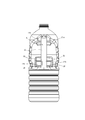
- the container with a handle includes a bottomed cylindrical container body and a handle having a protruding engagement portion that engages with the container body, and the container body engages the handle.
- a handle engaging portion that engages with the portion, and at least a part of the handle engaging portion is formed at a position covered by the handle when the handle-equipped container is viewed from the handle side.
- a pressure mark formed by an engaging portion forming member included in a mold for manufacturing the container with a handle is formed on a part of the container main body including the handle engaging portion. At least a part of the pressurization mark may be formed at a position covered by the handle when the handle-equipped container is viewed from the handle side.
- the handle engaging portion along the shape of the handle can be formed in the container, and the handle-attached container that is difficult to remove can be manufactured by deeply engaging the handle engaging portion and the handle. .
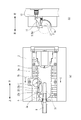
- FIG. 1A is a view showing a mold for a container with a handle according to the present invention
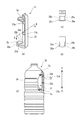
- FIG. 1B is a cross-sectional view taken along the line AA in FIG. 2 (a) is a perspective view showing a handle attached to the container
- FIG. 2 (b) is a bottom view of the handle shown in FIG. 2 (a)
- FIG. 2 (c) is a view of FIG. 2 (a).
- FIG. 2D is a cross-sectional view taken along the line BB
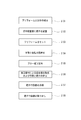
- FIG. 2D is a view showing a container with a handle. It is a flowchart which shows the manufacture procedure of a container with a handle.
- FIG. 1B is a cross-sectional view taken along the line AA in FIG. 2 (a) is a perspective view showing a handle attached to the container
- FIG. 2 (b) is a bottom view of the handle shown in FIG. 2 (a)
- FIG. 2 (c) is a view of FIG. 2 (a).
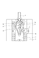
- FIG. 4 (a) is a view showing a state in which a handle is incorporated into a mold for a container with a handle and a preform is inserted
- FIG. 4 (b) is a cross-sectional view taken along line CC in FIG. 4 (a).
- FIG. It is a figure which shows one process in which the preform is blow-molded.
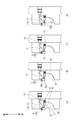
- FIGS. 6A to 6D are views showing a process in which the preform and the handle are engaged by pressure applied by the pressure member during blow molding. It is a figure which shows the container with which the handle was attached.
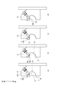
- FIGS. 8A to 8D are views showing a process in which the preform and the handle are engaged by the pressing member having a form different from that of the pressing member shown in FIG.
- FIG. 1 shows a mold 1 for a container with a handle used for producing a container with a handle.
- the container mold 1 with a handle is composed of two halves 2.
- FIG. 1A shows one of the half dies 2.
- the half mold 2 is formed with a recess (cavity) 3 having the shape of the container portion of the container with handle.
- the cavity 3 has an inner wall surface 3a that forms the outer shape of the container.
- a handle arrangement part 6 for arranging the handle 5 is provided at the upper part of the cavity 3.
- the handle arrangement part 6 has a concave shape along the outer shape of the handle 5 described later.
- the outer shape of the handle 5 when the handle 5 is arranged in the handle arranging portion 6 is indicated by a broken line.
- the handle placement portion 6 is provided with fixing pins 7a and 7b for fixing the handle.
- an insertion portion 8 into which a preform is inserted is provided in the upper portion of the half mold 2 (the mouth portion molding portion of the container).
- FIG. 1 (b) shows a cross-sectional view along the line AA in FIG. 1 (a).
- the tips of the mounting arms 5 a and 5 b of the handle 5 protrude inward from the cavity 3 of the half-die 2, that is, from the inner wall surface 3 a of the cavity 3. It is arranged with.
- FIG. 2 is a view for explaining the handle 5.
- the handle 5 includes a gripping portion 22, an upper mounting arm 5a, and a lower mounting arm 5b.
- the handle 5 is attached to the recessed part 21 of the container 20 with a handle along the up-down direction, as shown in FIG.2 (d).
- the grip portion 22 is a portion for gripping by hand when holding the container 20 with a handle.
- the holding portion 22 is formed with holding and positioning holes 23a and 23b into which the fixing pins 7a and 7b (see FIG. 1A) of the handle placement portion 6 are inserted.
- the upper mounting arm 5 a of the handle 5 protrudes from the vicinity of the upper end of the grip portion 22 toward the inside of the container body 24.
- the lower mounting arm 5 b of the handle 5 protrudes from the vicinity of the lower end of the grip portion 22 toward the inside of the container main body 24.
- the upper attachment arm 5a and the lower attachment arm 5b are engaged with the upper portion 21a and the lower portion 21b of the recess 21 of the container body 24, respectively.
- FIG. 1B the lower mounting arm 5b of the handle 5 is indicated by a broken line.
- an open space 10 in which the inner wall surface 3 a does not exist is formed around (periphery) the position where the lower mounting arm 5 b is arranged.
- This space 10 is a region where the inner wall surface 3a forming the cavity 3 is partially missing on both the left and right sides of the lower mounting arm 5b.
- the half mold 2 is provided with a pressurizing member (an example of an engaging portion forming member) 11 configured to be rotatable around the rotating shaft 12.
- a retractable hydraulic piston member 13 is provided on the back surface of the pressure member 11 (the right surface in FIG. 1B) in contact with the back surface of the pressure member 11, and this piston member. The pressure member 11 is pushed by the expansion / contraction of 13 and is rotated around the rotation shaft 12.
- a pressure surface 11 a is formed at the tip of the pressure member 11.
- the shape and position of the pressure member 11 are set so that when the pressure member 11 rotates around the rotation shaft 12, the pressure surface 11 a closes the space 10 formed around the lower mounting arm 5 b of the handle 5.
- the pressure member 11 and the space 10 have a nested structure in which the pressure surface 11 a of the pressure member 11 enters the space 10 so as to close the space 10.
- the pressure surface 11a is set at a position outside the inner wall surface 3a (an example of the first position).
- the piston member 13 is controlled to be in a contracted state, and the pressurizing member 11 has the rotary shaft 12 as viewed from below the half-die 2 (from the direction shown in FIG. 1B). Is rotated clockwise and maintained at a position in contact with the piston member 13 as shown in FIG.
- the pressure surface 11a is set to be disposed at a position (an example of the second position) that forms a part of the inner wall surface 3a.
- the piston member 13 is controlled to be extended.
- the pressure member 11 is pushed by the extended piston member 13 counterclockwise around the rotating shaft 12 when the half die 2 is viewed from below (from the direction shown in FIG. 1B). Rotating around, the pressure surface 11a is maintained at a position that covers the space 10 formed around the lower attachment arm 5b.
- the pressure member 11 is connected to a heat source unit (not shown) that can adjust the temperature of the pressure surface 11a.
- the heat source section has a heat medium. When the pressure surface 11a is heated, the heat medium heated to a predetermined temperature by the temperature control device is supplied to the pressure member 11, and the pressure surface 11a is Raise to temperature.
- a bottomed cylindrical preform 31 is formed in advance by injection molding using a material such as polyester resin.
- the handle 5 is formed by injection molding using a polyester resin or the like (step S101).
- step S102 an example of a pre-blow process.
- the preform 31 to be the container body 24 is inserted and set in the cavity 3 of the half mold 2 (step S103: an example of the pre-blow process).
- the preform 31 retains the amount of heat at the time of injection molding and is in an appropriate temperature for blow molding, or after cooling to room temperature after injection molding, the cavity 31 is heated to the appropriate temperature for blow molding and adjusted in temperature. Inserted inside.
- the appropriate temperature is set to 100 ° C to 120 ° C.
- step S102 and step S103 may be performed simultaneously, that is, the handle 5 and the preform 31 may be set on the mold 1 simultaneously.
- the handle 5 is fixed by inserting the fixing pins 7a and 7b of the handle arrangement portion 6 into the holding and positioning holes 23a and 23b formed in the grip portion 22.
- the distal ends of the upper mounting arm 5 a and the lower mounting arm 5 b of the handle 5 are arranged so as to protrude from the inner wall surface 3 a of the cavity 3 into the cavity 3.
- the preform 31 is set so as to extend straight into the cavity 3 along the central axis in the vertical direction of the cavity 3.
- the pressurization member 11 has the pressurization surface 11a arranged at a position outside the inner wall surface 3a. In this way, the handle 5 and the preform 31 are set in the half mold 2.
- step S104 the molds 2 and 2 are clamped.
- blow molding for forming the container 20 with a handle is started (step S105). Blow molding is performed by blowing high-pressure air into a preform 31 set in the cavity 3.
- FIG. 5 shows a process of blow molding in which air is blown into the preform 31 and the preform 31 expands.
- the stretching rod 41 is inserted into the preform 31 from the insertion portion 8, and when the stretching rod 41 is lowered, the preform 31 extends in the vertical center axis direction. Further, the preform 31 swells in the left-right direction by the high-pressure air introduced from the distal end of the insertion portion 8.
- the preform 31 is stretched by introducing air from the tip of the insertion portion 8 at the same time as or after the lowering of the stretching rod 41. Therefore, the preform 31 bulges in the left-right direction with the upper portion leading downward and sticks to the inner wall surface 3 a of the cavity 3.
- the swelled preform 31 comes into contact with the upper mounting arm 5a of the handle 5 so as to cover the upper mounting arm 5a from above and engages with the upper mounting arm 5a, and the upper portion 21a of the recess 21 of the container body 24 (see FIG. 2D). ) Will be formed.
- the preform 31 comes into contact with the lower mounting arm 5 b and engages with the lower mounting arm 5 b.
- the entire outer shape of the lower portion 21b of the recess 21 and the container body 24 is formed. In this way, the preform 31 is inflated.
- a handle engaging portion that engages with the lower mounting arm 5 b of the handle 5 is provided. 24 (step S106).
- the handle engaging portion is formed by pressurizing and deforming a part of the preform swelled by the pressure member 11.
- FIG. 6 (a) shows a state where the blow has not started.
- the handle 5 and the preform 31 are set at predetermined positions, and the pressure member 11 has a pressure surface 11a disposed outside the inner wall surface 3a (an example of a first position).
- a space 10 in which the inner wall surface 3a is missing is formed around the lower mounting arm 5b of the handle 5 that is set.
- FIG. 6B shows a state in which the preform 31 swells by blowing, the swelled preform 31 sticks to the inner wall surface 3a of the cavity 3, and the outer shape of the container body 24 is being formed.
- the swelled preform 31 enters the space 10 where the inner wall surface 3a does not exist. However, the preform 31 does not enter the curved recess 25a of the lower mounting arm 5b at this stage.
- the pressurizing member 11 is still in a state where the pressurizing surface 11a is arranged at a position outside the inner wall surface 3a.
- FIG. 6C shows a state in which the preform 31 swelled by blowing and has entered the space 10 has swelled to the outside from the position that is the outer shape of the container body 24.
- the swelled preform 31 has reached a position in contact with the pressing surface 11a of the pressing member 11 disposed outside the inner wall surface 3a.
- the hydraulic piston member 13 is driven, and the pressure member 11 starts rotating (counterclockwise in FIG. 6C). Note that the preform 31 that bulges and enters the space 10 at the start of this operation does not enter the curved recess 25a of the lower mounting arm 5b, and a gap 51 is formed between the preform 31 and the curved recess 25a.
- the timing at which the pressure member 11 is driven can be set as a point in time when a predetermined time has elapsed since the start of blow molding.
- the predetermined time may be a point in time when the swelled preform 31 swells to the outside of the outer shape of the container body 24 in the space 10 and the swelled preform 31 comes into contact with (or reaches) the pressure surface 11a of the pressure member 11.
- it may be a point in time when the swelled preform 31 bulges (reaches) to the outside beyond the position of the outer shape of the container.
- FIG. 6D shows a state in which the container body 24 (preform 31) and the handle 5 are engaged by the pressurizing member 11.
- the pressure surface 11a is moved to a position (an example of the second position) that forms a part of the inner wall surface 3a of the cavity 3 (a portion of the space 10 where the inner wall surface 3a is missing). The That is, the pressurizing surface 11a is moved to the position of the outer shape of the container body 24.
- the portion of the swelled preform 31 that swells outside the outer shape of the container body 24 is pushed back to the position of the outer shape of the container body 24.
- the preform 31 that has been pushed back is deformed by pressurization from the pressurizing surface 11 a, and the portion that comes into contact with the pressurizing surface 11 a is formed in the outer shape of the container body 24.
- the preform 31 that has been pushed back is pushed toward the curved concave portion 25a of the lower mounting arm 5b, and enters the gap 51 that existed around the curved concave portion 25a in FIG. 6C.
- the pressurizing surface 11a is inclined as shown in FIG. 6C at the start of the movement (upward to the left in the figure), and the preform 31 is gradually pushed toward the gap 51 by the pressurizing surface 11a by the rotational movement. .
- the preform 31 on the curved concave portion 25a side is deformed along the shape of the curved concave portion 25, and that portion can be engaged with a protruding engaging portion 26a formed at the tip of the lower mounting arm 5b.
- a handle engaging portion 52 is formed. That is, a handle engaging portion 52 that engages with the engaging portion 26a of the lower mounting arm 5b is formed on the preform 31 by applying pressure from the pressing member 11.
- Steps S105 to S106 described above are an example of a blow molding process, and step S106 is also an example of an engaging portion forming process.
- the preform 31 is kept in close contact with the inner wall surface 3a of the cavity 3 and cooled so as to have the final shape of the container 20 with a handle (step S107). Thereafter, the air is exhausted, the mold is opened, and the handle-equipped container 20 with which the handle 5 is engaged is taken out (step S108).
- the pressurizing surface 11a of the pressurizing member 11 is positioned outside the inner wall surface 3a and a part of the inner wall surface 3a. It is possible to move between the positions forming the. For this reason, when the preform 31 is inflated by blow molding, the pressurization surface 11a of the pressurization member 11 is arranged at a position outside the inner wall surface 3a, so that the preform 31 is extended to the outside of the outer shape of the container body 24. Can be inflated.
- the preform 31 can be pushed in the direction of the curved recess 25a of the handle 5 (lower mounting arm 5b), and a handle engaging portion 52 corresponding to the shape of the curved recess 25a is formed in the preform 31 (container body 24). be able to.
- the handle engaging portion 52 formed on the container main body 24 and the handle 5 (particularly, the engaging portion 26a formed on the distal end portion of the lower mounting arm 5b) can be engaged deeply without any gap, and the handle 5 Can be manufactured, and the container 20 with a handle having a high attachment strength can be manufactured.
- the pressurizing surface 11a of the pressurizing member 11 is disposed outside the inner wall surface 3a and the preform 31 is inflated outside the outer shape of the container main body 24, the handle that has been so narrow that it has not been able to enter.
- the preform 31 can be reliably wound into the gap between the lower mounting arms 5b. Therefore, the container 20 with a handle provided with the handle 5 with little backlash and difficult to remove can be manufactured.
- the timing which drives the pressurization member 11 can be set as the time when predetermined time passed since blow molding was started, after calculating
- the handle-equipped container 20 having a high attachment strength that prevents the handle 5 from coming off can be efficiently manufactured, it can be applied to a high cycle machine that cannot secure a sufficient blow time in the manufacturing process.
- a pressurization mark 28 that can be observed by a measuring instrument may be formed.
- the pressurization mark 28 is formed when the swelled portion of the preform 31 is pressed by the pressurization surface 11a of the pressurization member 11 and deformed in step S106 described above. At least a part of the pressurization mark 28 is formed in the handle engaging portion 52.
- the pressure surface 11a has a flat surface at least in a position range facing the engaging portions 26a and 26b of the handle 5.
- the pressurization mark 28 has a flat surface structure extending at least in the vertical direction on the curved concave portions 25a and 25b side of the handle 5.
- the pressurization mark 28 in the present example extends on the upper and lower sides and the right and left sides of the engaging portions 26a and 26b on the convex lower portion 21b, and is a concave flat shape having a wide area. It is formed as.
- At least a part of the handle engaging portion 52 is formed at a position covered by the grip portion 22 of the handle 5 when the handle-equipped container 20 is viewed from the handle side. Further, a part of the pressurization mark 28 formed on the lower portion 21 b of the container body 24 is also formed at a position covered with the grip portion 22 of the handle 5 when the container 20 with the handle is viewed from the handle side.
- the lower mounting arm 5b of the handle 5 and the handle engaging portion 52 are deeply engaged with each other. Further, a part of the upper portion 21a of the concave portion 21 of the container body 24 is engaged so as to cover the upper mounting arm 5a (see FIG. 2) of the handle 5 from above.
- the handle 5 attached in this way has a high attachment strength that prevents the handle 5 from coming off. For this reason, even when a high-temperature liquid (for example, drinking water, seasonings, liquor, etc.) is filled in the container main body 24, the grip 5 is less loose and the handle 5 is difficult to come off.
- a high-temperature liquid for example, drinking water, seasonings, liquor, etc.
- FIG. 8 shows a modification of the pressure member.
- the pressurizing member 61 shown in FIG. 8 is a piston type and is different from the pressurizing member 11 shown in FIG. 6 which is a rotary type.
- FIGS. 8A to 8D show a process in which the container main body 24 (preform 31) and the handle 5 are engaged by the pressurizing member 61.
- FIG. When compared with FIGS. 6 (a) to 6 (d), the members other than the pressure member have the same configuration, and therefore the same reference numerals are given and description thereof is omitted.
- the pressure member 61 is installed toward the space 10 where the inner wall surface 3a formed around the lower mounting arm 5b does not exist.
- the pressure surface 61a When the pressure member 61 is retracted, the pressure surface 61a is disposed at a position outside the inner wall surface 3a (an example of a first position). On the other hand, in the protruding state, the pressure surface 61a is moved to a position (an example of the second position) that forms the outer shape of the container body 24. The pressing member 61 is driven and protruded when the swelled preform 31 comes into contact with the pressing surface 61a (at the time shown in FIG. 8C).
- the protruding pressure surface 61 a of the pressure member 61 moves to the position of the outer shape of the container body 24 and closes the space 10.
- the swelled preform 31 is pushed back to engage with the curved concave portion 25a of the lower mounting arm 5b (particularly, the engaging portion 26a formed at the tip of the lower mounting arm 5b).
- a matching handle engaging portion 52 is formed.
- the pressure surface 61 a of the pressure member 61 is formed such that the tip portion close to the handle 5 is slightly bent toward the tip portion of the handle 5. With such a configuration, in the pressure member 61, the preform 31 is more reliably placed on the side closer to the handle 5 (on the back side (rear side) of the engaging portion 26a) by the refracted tip portion of the pressure surface 61a. It can push in and can make the clearance gap with the handle 5 small.
- the temperature of the pressure surfaces 11a and 61a is increased (for example, increased to about 100 ° C.), It is good also as a structure which heat sets the pressurization surfaces 11a and 61a which contact.
- the temperature of the pressurizing surfaces 11a and 61a is low, the swelled portion of the preform 31 is cooled after contact with the pressurizing surfaces 11a and 61a and is not easily deformed. Need to control.
- the swelled portion of the preform is desired even if there is some error in the timing of driving the pressurizing members 11 and 61. It can be transformed into a shape.
- the handle engaging portion 52 that engages with the distal end portion (the curved portions 25a and 25b, particularly the engaging portions 26a and 26b) of the lower mounting arm 5b is heat set. can do. Therefore, the heat resistance of the handle engaging part 52 can be improved, and the handle 5 can be prevented from coming off by preventing shrinkage and lowering of the handle attachment strength due to shrinkage and deformation when filled with high-temperature seasoning, liquor or the like.
- the container 20 can be manufactured.
Landscapes
- Engineering & Computer Science (AREA)
- Mechanical Engineering (AREA)
- Manufacturing & Machinery (AREA)
- Ceramic Engineering (AREA)
- Blow-Moulding Or Thermoforming Of Plastics Or The Like (AREA)
- Moulds For Moulding Plastics Or The Like (AREA)
- Details Of Rigid Or Semi-Rigid Containers (AREA)
Abstract
Description
把手付容器用金型1は、2つの半割り金型2から構成される。図1(a)には、そのうちの一方の半割り金型2が示されている。半割り金型2には、把手付容器の容器部分の形状を有した凹部(キャビティ)3が形成されている。キャビティ3は容器の外形を形成する内壁面3aを有する。
図2(a)示すように、把手5は、把持部22と、上部取付腕5aおよび下部取付腕5bを有している。また、把手5は、図2(d)に示すように、把手付容器20の凹部21に、その上下方向に沿って取り付けられるものである。
本出願は、2012年12月14日出願の日本特許出願・出願番号2012-273516に基づくものであり、その内容はここに参照として取り込まれる。
Claims (5)
- 把手配置部に把手を配置し、キャビティ内に有底筒状のプリフォームを挿入してブロー成形することにより前記把手が容器の一部に係合された把手付容器を製造するための把手付容器用金型であって、
前記容器の外形を形成する内壁面と、
前記容器の一部に前記把手と係合する把手係合部を形成する係合部形成部材と、
を備え、
前記係合部形成部材は、前記内壁面よりも外側の位置である第1の位置と前記内壁面の一部を形成する第2の位置との間を移動可能であることを特徴とする把手付容器用金型。 - 前記係合部形成部材は、当該係合部形成部材の温度を調節するための熱源部と接続されていることを特徴とする請求項1に記載の把手付容器用金型。
- 把手配置部に把手を配置し、金型のキャビティ内に有底筒状のプリフォームを挿入するブロー前段工程と、
前記プリフォーム内に空気を吹き込んで膨らませて容器を形成するブロー成形工程とを有し、
前記ブロー成形工程において、膨らむプリフォームが前記把手の周辺において前記容器の外形を形成する内壁面よりも外側の位置まで膨らんだときに、前記内壁面よりも外側の位置に配置されている係合部形成部材を前記内壁面の一部を形成する位置まで移動させて前記外側の位置まで膨らんだ部分を押し戻すことにより、前記把手と係合する把手係合部を前記容器の一部に形成する係合部形成工程を有することを特徴とする把手付容器の製造方法。 - 有底筒状の容器本体と、前記容器本体と係合する突起状の係合部を有する把手と、を備える把手付容器であって、
前記容器本体は、前記把手の係合部と係合する把手係合部を有し、
前記把手係合部の少なくとも一部は、当該把手付容器を把手側から見て把手によって覆われる位置に形成されていることを特徴とする把手付容器。 - 前記把手係合部を含む前記容器本体の一部には、把手付容器を製造するための金型が有する係合部形成部材によって形成された加圧痕が形成され、
前記加圧痕の少なくとも一部は、当該把手付容器を把手側から見て把手によって覆われる位置に形成されていることを特徴とする請求項4に記載の把手付容器。
Priority Applications (6)
| Application Number | Priority Date | Filing Date | Title |
|---|---|---|---|
| MX2015007595A MX2015007595A (es) | 2012-12-14 | 2013-12-11 | Molde para envases con asa, metodo para fabricar el envase con asa, y envase con asa. |
| JP2014552073A JP6324906B2 (ja) | 2012-12-14 | 2013-12-11 | 把手付容器用金型、把手付容器の製造方法および把手付容器 |
| EP13862372.3A EP2933088B1 (en) | 2012-12-14 | 2013-12-11 | Mold for vessel with handle, method for producing vessel with handle, and vessel with handle |
| US14/651,603 US10150242B2 (en) | 2012-12-14 | 2013-12-11 | Mold for container with handle |
| CN201380065197.0A CN104837604B (zh) | 2012-12-14 | 2013-12-11 | 带把手容器用模具、带把手容器的制造方法和带把手容器 |
| ZA2015/04271A ZA201504271B (en) | 2012-12-14 | 2015-06-12 | Mold for container with handle, method for manufacturing container with handle, and container with handle |
Applications Claiming Priority (2)
| Application Number | Priority Date | Filing Date | Title |
|---|---|---|---|
| JP2012273516 | 2012-12-14 | ||
| JP2012-273516 | 2012-12-14 |
Publications (1)
| Publication Number | Publication Date |
|---|---|
| WO2014092135A1 true WO2014092135A1 (ja) | 2014-06-19 |
Family
ID=50934419
Family Applications (1)
| Application Number | Title | Priority Date | Filing Date |
|---|---|---|---|
| PCT/JP2013/083258 Ceased WO2014092135A1 (ja) | 2012-12-14 | 2013-12-11 | 把手付容器用金型、把手付容器の製造方法および把手付容器 |
Country Status (8)
| Country | Link |
|---|---|
| US (1) | US10150242B2 (ja) |
| EP (1) | EP2933088B1 (ja) |
| JP (2) | JP6324906B2 (ja) |
| CN (1) | CN104837604B (ja) |
| MX (1) | MX2015007595A (ja) |
| TW (1) | TWI572473B (ja) |
| WO (1) | WO2014092135A1 (ja) |
| ZA (1) | ZA201504271B (ja) |
Cited By (3)
| Publication number | Priority date | Publication date | Assignee | Title |
|---|---|---|---|---|
| EP2975170A1 (en) * | 2014-07-15 | 2016-01-20 | Dongbu Daewoo Electronics Corporation | Washing machine and method of manufacturing the same |
| WO2016181850A1 (ja) * | 2015-05-08 | 2016-11-17 | 日精エー・エス・ビー機械株式会社 | 把手および把手付き容器 |
| JP2017047690A (ja) * | 2013-06-28 | 2017-03-09 | 日精エー・エス・ビー機械株式会社 | 把手付き容器の成形装置及びそれに用いる成形用金型並びに成形用金型ユニット |
Families Citing this family (5)
| Publication number | Priority date | Publication date | Assignee | Title |
|---|---|---|---|---|
| FR3027248B1 (fr) * | 2014-10-17 | 2016-12-09 | Sidel Participations | Moule a plan de joint sureleve pour la fabrication de recipients |
| DE102018004159A1 (de) * | 2018-05-23 | 2019-11-28 | Khs Corpoplast Gmbh | Mehrteilig ausgebildete Form für die umformende Herstellung von Behältern mit Griff, Umformstation, Umformrad und Umformmaschine mit einer solchen Form, Verfahren zur Herstellung eines Behälters mit Griff und nach diesem Verfahren hergestellter Behälter |
| KR102260061B1 (ko) * | 2020-06-11 | 2021-06-04 | 형제프라콘(주) | 손잡이를 갖춘 페트병 제조방법과 이에 따른 제조장치 및 이에 의해 제조된 페트병 |
| EP4585385A1 (en) * | 2022-09-06 | 2025-07-16 | Nissei ASB Machine Co., Ltd. | Device and method for producing resin container |
| USD1126002S1 (en) | 2024-10-08 | 2026-05-12 | Co2Pac Limited | Container |
Citations (5)
| Publication number | Priority date | Publication date | Assignee | Title |
|---|---|---|---|---|
| JP2005153919A (ja) * | 2003-11-21 | 2005-06-16 | Sugi Plastic Industry Co Ltd | 把手付きプラスチックボトル及びそれに使用する把手 |
| JP2008179400A (ja) | 2007-01-25 | 2008-08-07 | Mitsubishi Plastics Ind Ltd | プラスチックボトル取付用把手および把手付プラスチックボトル |
| JP2011011479A (ja) * | 2009-07-03 | 2011-01-20 | Toyo Seikan Kaisha Ltd | ブロー成形方法 |
| JP2011189993A (ja) | 2011-06-22 | 2011-09-29 | Toyo Seikan Kaisha Ltd | 把手付耐熱容器の製造方法 |
| JP2011246200A (ja) * | 2011-07-15 | 2011-12-08 | Yoshino Kogyosho Co Ltd | 把手付きボトル |
Family Cites Families (24)
| Publication number | Priority date | Publication date | Assignee | Title |
|---|---|---|---|---|
| US4273246A (en) * | 1979-04-10 | 1981-06-16 | Thompson Mortimer S | Bottles with attached handles and a method of forming the same |
| US4257525A (en) * | 1979-04-10 | 1981-03-24 | Thompson Mortimer S | Bottle with attached handle |
| US4952133A (en) * | 1986-10-13 | 1990-08-28 | Mitsubishi Plastics Industries Limited | Apparatus for forming a blown bottle with a handle |
| US4964522A (en) * | 1987-05-09 | 1990-10-23 | Mitsubishi Plastics Industries Limited | Thermoplastic blown bottle with a handle |
| US4982869A (en) * | 1989-11-07 | 1991-01-08 | Robbins Edward S Iii | Pivoting handle type pitcher for thin walled container |
| EP0482203B2 (en) | 1990-04-12 | 2001-01-10 | Mitsubishi Plastics Inc. | Method of manufacturing bottle with hand-grip |
| GB2251844B (en) * | 1990-12-29 | 1995-07-05 | A K Tech Lab Inc | Bottle with handle |
| JP3096995B2 (ja) | 1991-12-06 | 2000-10-10 | 株式会社吉野工業所 | 把手付き壜体用把手 |
| US5469612A (en) * | 1993-12-02 | 1995-11-28 | Continental Pet Technologies, Inc. | Method for forming a strain-hardenable plastic container |
| JPH08169059A (ja) * | 1994-12-19 | 1996-07-02 | Nissei Asb Mach Co Ltd | 把手付き合成樹脂製容器および容器用把手ならびに把手付き合成樹脂製容器の成形方法 |
| US5637167A (en) * | 1995-05-22 | 1997-06-10 | Continental Pet Technologies, Inc. | Method for post-mold attachment of a handle to a strain-oriented plastic container |
| US6444158B1 (en) * | 1996-05-14 | 2002-09-03 | Continental Pet Technologies, Inc. | Handled plastic container |
| US6012597A (en) * | 1998-03-18 | 2000-01-11 | Mitsubishi Plastics, Inc. | Polyester bottle with a handle and method of manufacturing the same |
| US6855289B2 (en) * | 2001-11-27 | 2005-02-15 | Graham Packaging Pet Technologies, Inc. | Method and apparatus for cooling during in-mold handle attachment |
| JP4060117B2 (ja) * | 2002-04-24 | 2008-03-12 | 株式会社エフティエス | インサートブロー成形方法及びその装置 |
| EP2347883B1 (en) | 2002-07-31 | 2015-07-08 | Yoshino Kogyosho Co., Ltd. | Synthetic resin bottle with a handle |
| US7229587B2 (en) * | 2003-04-03 | 2007-06-12 | Custom - Pak, Inc. | Blow molded container having holes therein and method and apparatus for facilitating the creation thereof |
| JP2006103003A (ja) | 2004-09-30 | 2006-04-20 | Aoki Technical Laboratory Inc | ボトル側部の把手インサート成形方法及び装置 |
| KR100778916B1 (ko) * | 2006-03-07 | 2007-11-22 | 새한프라텍 주식회사 | 합성수지 용기의 손잡이 |
| US7600655B2 (en) * | 2006-05-10 | 2009-10-13 | Graham Packaging Company, Llp | Anchor for attachment of a handle to a container |
| US7524181B2 (en) * | 2006-07-18 | 2009-04-28 | Fu-Chuan Chiang | Blowing assembly |
| US8231021B2 (en) | 2007-06-01 | 2012-07-31 | Magata Fuji Chemical Co., Ltd. | Strip-shaped handle part for drinking water bottle |
| US8613882B2 (en) * | 2011-01-24 | 2013-12-24 | Bottle-Top Development Co. | Method of planting a handle and a bottle parison to a mold of blow-molding modules for manufacturing plastic containers |
| EP2749398B1 (en) * | 2011-08-22 | 2016-05-11 | Nissei Asb Machine Co., Ltd. | Blow-molding method for container with handle and blow-molding equipment |
-
2013
- 2013-12-11 WO PCT/JP2013/083258 patent/WO2014092135A1/ja not_active Ceased
- 2013-12-11 CN CN201380065197.0A patent/CN104837604B/zh active Active
- 2013-12-11 US US14/651,603 patent/US10150242B2/en active Active
- 2013-12-11 EP EP13862372.3A patent/EP2933088B1/en active Active
- 2013-12-11 MX MX2015007595A patent/MX2015007595A/es active IP Right Grant
- 2013-12-11 JP JP2014552073A patent/JP6324906B2/ja active Active
- 2013-12-13 TW TW102146065A patent/TWI572473B/zh active
-
2015
- 2015-06-12 ZA ZA2015/04271A patent/ZA201504271B/en unknown
-
2018
- 2018-04-11 JP JP2018076176A patent/JP6657287B2/ja active Active
Patent Citations (5)
| Publication number | Priority date | Publication date | Assignee | Title |
|---|---|---|---|---|
| JP2005153919A (ja) * | 2003-11-21 | 2005-06-16 | Sugi Plastic Industry Co Ltd | 把手付きプラスチックボトル及びそれに使用する把手 |
| JP2008179400A (ja) | 2007-01-25 | 2008-08-07 | Mitsubishi Plastics Ind Ltd | プラスチックボトル取付用把手および把手付プラスチックボトル |
| JP2011011479A (ja) * | 2009-07-03 | 2011-01-20 | Toyo Seikan Kaisha Ltd | ブロー成形方法 |
| JP2011189993A (ja) | 2011-06-22 | 2011-09-29 | Toyo Seikan Kaisha Ltd | 把手付耐熱容器の製造方法 |
| JP2011246200A (ja) * | 2011-07-15 | 2011-12-08 | Yoshino Kogyosho Co Ltd | 把手付きボトル |
Non-Patent Citations (1)
| Title |
|---|
| See also references of EP2933088A4 |
Cited By (8)
| Publication number | Priority date | Publication date | Assignee | Title |
|---|---|---|---|---|
| JP2017047690A (ja) * | 2013-06-28 | 2017-03-09 | 日精エー・エス・ビー機械株式会社 | 把手付き容器の成形装置及びそれに用いる成形用金型並びに成形用金型ユニット |
| EP2975170A1 (en) * | 2014-07-15 | 2016-01-20 | Dongbu Daewoo Electronics Corporation | Washing machine and method of manufacturing the same |
| WO2016181850A1 (ja) * | 2015-05-08 | 2016-11-17 | 日精エー・エス・ビー機械株式会社 | 把手および把手付き容器 |
| CN107531361A (zh) * | 2015-05-08 | 2018-01-02 | 日精Asb机械株式会社 | 把手以及带有把手的容器 |
| TWI613126B (zh) * | 2015-05-08 | 2018-02-01 | 日精Asb機械股份有限公司 | 把手及帶把手容器 |
| JPWO2016181850A1 (ja) * | 2015-05-08 | 2018-02-22 | 日精エー・エス・ビー機械株式会社 | 把手および把手付き容器 |
| US10618694B2 (en) | 2015-05-08 | 2020-04-14 | Nissei Asb Machine Co., Ltd. | Handle and container with handle |
| CN107531361B (zh) * | 2015-05-08 | 2020-06-16 | 日精Asb机械株式会社 | 把手以及带有把手的容器 |
Also Published As
| Publication number | Publication date |
|---|---|
| JP6657287B2 (ja) | 2020-03-04 |
| TWI572473B (zh) | 2017-03-01 |
| JP2018108744A (ja) | 2018-07-12 |
| US20150328818A1 (en) | 2015-11-19 |
| ZA201504271B (en) | 2016-11-30 |
| EP2933088B1 (en) | 2020-11-11 |
| TW201441009A (zh) | 2014-11-01 |
| JP6324906B2 (ja) | 2018-05-16 |
| MX2015007595A (es) | 2016-03-21 |
| EP2933088A4 (en) | 2016-09-21 |
| CN104837604A (zh) | 2015-08-12 |
| JPWO2014092135A1 (ja) | 2017-01-12 |
| EP2933088A1 (en) | 2015-10-21 |
| CN104837604B (zh) | 2017-06-20 |
| US10150242B2 (en) | 2018-12-11 |
Similar Documents
| Publication | Publication Date | Title |
|---|---|---|
| JP6324906B2 (ja) | 把手付容器用金型、把手付容器の製造方法および把手付容器 | |
| JP6060182B2 (ja) | プレフォームの最適化された底部輪郭を形成する方法および装置 | |
| CN101823328B (zh) | 用于生产塑料容器的设备 | |
| JP5691521B2 (ja) | 合成樹脂製容器の製造方法 | |
| JP7457077B2 (ja) | 首曲がり容器の製造方法、温度調整用金型、ブロー成形装置およびブロー成形方法 | |
| WO2016181850A1 (ja) | 把手および把手付き容器 | |
| JP6796592B2 (ja) | 金型、ブロー成形装置、およびブロー成形方法 | |
| KR100291113B1 (ko) | 열가소성 물질의 용기제조방법과 장치 | |
| CN101370640B (zh) | 形成拉伸吹塑容器的方法及装置 | |
| JP5567310B2 (ja) | 偏平容器のブロー成形方法 | |
| JP6872636B2 (ja) | 瓶のための厚さ可変プリフォーム | |
| JP6975829B2 (ja) | プリフォームに最適なネック部輪郭を作成するための方法及び装置 | |
| JP6464157B2 (ja) | プリフォームの最適な底部輪郭を製造するための方法及び装置 | |
| JP2017109484A (ja) | 容器の成形加工用の幅広のベントを有する金型底部 | |
| JP3410363B2 (ja) | 把手付き二軸延伸ボトルのブロー金型 | |
| JP3470580B2 (ja) | 中空容器の成形方法および成形装置 | |
| JP6079288B2 (ja) | 合成樹脂製容器の製造方法 | |
| CN105189085A (zh) | 用于制造稳固性增强的容器的具有偏置分型面的模型 | |
| CN110719835B (zh) | 模具 | |
| JP6540150B2 (ja) | インサート部品が埋設されたブロー成形体の製造方法 | |
| KR102292071B1 (ko) | 연신 블로우 성형으로 균일한 두께의 제품을 제조하는 방법, 및 그 장치 | |
| JP2013208798A (ja) | 二重容器の製造方法 | |
| EP1097793A1 (en) | Method and apparatus for blow moulding articles with internal walls | |
| JP5367219B2 (ja) | タイヤの製造方法 | |
| JP2003062897A (ja) | ブロー成形方法 |
Legal Events
| Date | Code | Title | Description |
|---|---|---|---|
| 121 | Ep: the epo has been informed by wipo that ep was designated in this application |
Ref document number: 13862372 Country of ref document: EP Kind code of ref document: A1 |
|
| ENP | Entry into the national phase |
Ref document number: 2014552073 Country of ref document: JP Kind code of ref document: A |
|
| WWE | Wipo information: entry into national phase |
Ref document number: 14651603 Country of ref document: US |
|
| WWE | Wipo information: entry into national phase |
Ref document number: MX/A/2015/007595 Country of ref document: MX Ref document number: 2013862372 Country of ref document: EP |
|
| NENP | Non-entry into the national phase |
Ref country code: DE |