WO2014098127A1 - 放電ランプ点灯装置 - Google Patents
放電ランプ点灯装置 Download PDFInfo
- Publication number
- WO2014098127A1 WO2014098127A1 PCT/JP2013/083894 JP2013083894W WO2014098127A1 WO 2014098127 A1 WO2014098127 A1 WO 2014098127A1 JP 2013083894 W JP2013083894 W JP 2013083894W WO 2014098127 A1 WO2014098127 A1 WO 2014098127A1
- Authority
- WO
- WIPO (PCT)
- Prior art keywords
- discharge lamp
- lighting
- short
- time
- lighting device
- Prior art date
- Legal status (The legal status is an assumption and is not a legal conclusion. Google has not performed a legal analysis and makes no representation as to the accuracy of the status listed.)
- Ceased
Links
Images




Classifications
-
- H—ELECTRICITY
- H05—ELECTRIC TECHNIQUES NOT OTHERWISE PROVIDED FOR
- H05B—ELECTRIC HEATING; ELECTRIC LIGHT SOURCES NOT OTHERWISE PROVIDED FOR; CIRCUIT ARRANGEMENTS FOR ELECTRIC LIGHT SOURCES, IN GENERAL
- H05B41/00—Circuit arrangements or apparatus for igniting or operating discharge lamps
- H05B41/14—Circuit arrangements
- H05B41/26—Circuit arrangements in which the lamp is fed by power derived from DC by means of a converter, e.g. by high-voltage DC
- H05B41/28—Circuit arrangements in which the lamp is fed by power derived from DC by means of a converter, e.g. by high-voltage DC using static converters
- H05B41/288—Circuit arrangements in which the lamp is fed by power derived from DC by means of a converter, e.g. by high-voltage DC using static converters with semiconductor devices and specially adapted for lamps without preheating electrodes, e.g. for high-intensity discharge lamps, high-pressure mercury or sodium lamps or low-pressure sodium lamps
- H05B41/292—Arrangements for protecting lamps or circuits against abnormal operating conditions
- H05B41/2921—Arrangements for protecting lamps or circuits against abnormal operating conditions for protecting the circuit against abnormal operating conditions
-
- H—ELECTRICITY
- H01—ELECTRIC ELEMENTS
- H01J—ELECTRIC DISCHARGE TUBES OR DISCHARGE LAMPS
- H01J61/00—Gas-discharge or vapour-discharge lamps
- H01J61/84—Lamps with discharge constricted by high pressure
- H01J61/86—Lamps with discharge constricted by high pressure with discharge additionally constricted by close spacing of electrodes, e.g. for optical projection
-
- H—ELECTRICITY
- H01—ELECTRIC ELEMENTS
- H01J—ELECTRIC DISCHARGE TUBES OR DISCHARGE LAMPS
- H01J61/00—Gas-discharge or vapour-discharge lamps
- H01J61/02—Details
- H01J61/04—Electrodes; Screens; Shields
- H01J61/06—Main electrodes
- H01J61/073—Main electrodes for high-pressure discharge lamps
- H01J61/0732—Main electrodes for high-pressure discharge lamps characterised by the construction of the electrode
-
- H—ELECTRICITY
- H01—ELECTRIC ELEMENTS
- H01J—ELECTRIC DISCHARGE TUBES OR DISCHARGE LAMPS
- H01J61/00—Gas-discharge or vapour-discharge lamps
- H01J61/02—Details
- H01J61/04—Electrodes; Screens; Shields
- H01J61/06—Main electrodes
- H01J61/073—Main electrodes for high-pressure discharge lamps
- H01J61/0735—Main electrodes for high-pressure discharge lamps characterised by the material of the electrode
-
- H—ELECTRICITY
- H01—ELECTRIC ELEMENTS
- H01J—ELECTRIC DISCHARGE TUBES OR DISCHARGE LAMPS
- H01J61/00—Gas-discharge or vapour-discharge lamps
- H01J61/02—Details
- H01J61/24—Means for obtaining or maintaining the desired pressure within the vessel
- H01J61/26—Means for absorbing or adsorbing gas, e.g. by gettering; Means for preventing blackening of the envelope
-
- H—ELECTRICITY
- H05—ELECTRIC TECHNIQUES NOT OTHERWISE PROVIDED FOR
- H05B—ELECTRIC HEATING; ELECTRIC LIGHT SOURCES NOT OTHERWISE PROVIDED FOR; CIRCUIT ARRANGEMENTS FOR ELECTRIC LIGHT SOURCES, IN GENERAL
- H05B41/00—Circuit arrangements or apparatus for igniting or operating discharge lamps
- H05B41/02—Details
- H05B41/04—Starting switches
-
- H—ELECTRICITY
- H05—ELECTRIC TECHNIQUES NOT OTHERWISE PROVIDED FOR
- H05B—ELECTRIC HEATING; ELECTRIC LIGHT SOURCES NOT OTHERWISE PROVIDED FOR; CIRCUIT ARRANGEMENTS FOR ELECTRIC LIGHT SOURCES, IN GENERAL
- H05B41/00—Circuit arrangements or apparatus for igniting or operating discharge lamps
- H05B41/14—Circuit arrangements
- H05B41/26—Circuit arrangements in which the lamp is fed by power derived from DC by means of a converter, e.g. by high-voltage DC
- H05B41/28—Circuit arrangements in which the lamp is fed by power derived from DC by means of a converter, e.g. by high-voltage DC using static converters
- H05B41/288—Circuit arrangements in which the lamp is fed by power derived from DC by means of a converter, e.g. by high-voltage DC using static converters with semiconductor devices and specially adapted for lamps without preheating electrodes, e.g. for high-intensity discharge lamps, high-pressure mercury or sodium lamps or low-pressure sodium lamps
- H05B41/292—Arrangements for protecting lamps or circuits against abnormal operating conditions
- H05B41/2921—Arrangements for protecting lamps or circuits against abnormal operating conditions for protecting the circuit against abnormal operating conditions
- H05B41/2925—Arrangements for protecting lamps or circuits against abnormal operating conditions for protecting the circuit against abnormal operating conditions against abnormal lamp operating conditions
-
- H—ELECTRICITY
- H01—ELECTRIC ELEMENTS
- H01J—ELECTRIC DISCHARGE TUBES OR DISCHARGE LAMPS
- H01J61/00—Gas-discharge or vapour-discharge lamps
- H01J61/02—Details
- H01J61/12—Selection of substances for gas fillings; Specified operating pressure or temperature
- H01J61/16—Selection of substances for gas fillings; Specified operating pressure or temperature having helium, argon, neon, krypton, or xenon as the principle constituent
-
- Y—GENERAL TAGGING OF NEW TECHNOLOGICAL DEVELOPMENTS; GENERAL TAGGING OF CROSS-SECTIONAL TECHNOLOGIES SPANNING OVER SEVERAL SECTIONS OF THE IPC; TECHNICAL SUBJECTS COVERED BY FORMER USPC CROSS-REFERENCE ART COLLECTIONS [XRACs] AND DIGESTS
- Y02—TECHNOLOGIES OR APPLICATIONS FOR MITIGATION OR ADAPTATION AGAINST CLIMATE CHANGE
- Y02B—CLIMATE CHANGE MITIGATION TECHNOLOGIES RELATED TO BUILDINGS, e.g. HOUSING, HOUSE APPLIANCES OR RELATED END-USER APPLICATIONS
- Y02B20/00—Energy efficient lighting technologies, e.g. halogen lamps or gas discharge lamps
Definitions
- the present invention relates to a discharge lamp lighting device.
- the present invention relates to a discharge lamp lighting device used as a light source for a projector in a movie theater.
- a discharge lamp lighting device including such a discharge lamp includes a control unit that controls a current supplied to the discharge lamp at the start of lighting (see Patent Document 1), and a current supplied to the discharge lamp.
- a device see Patent Document 2 that includes a control unit that dims a discharge lamp by changing the above.
- the cathode is deformed as the lighting time elapses, thereby causing flicker.
- the time from the start of use of the discharge lamp to the frequent occurrence of flicker is called the flicker life.
- a xenon discharge lamp capable of obtaining a long flicker life a lamp having a cathode having a surface layer in which a striped tungsten carbide phase is formed in a tungsten phase has been proposed (Patent Document 3). reference.).
- the present invention has been made based on the circumstances as described above, and the object thereof is to suppress the generation of flicker even when the discharge lamp is lit for a long time, and a long flicker life can be obtained. It is to provide a discharge lamp lighting device.
- a discharge lamp lighting device includes an arc tube, an anode and a cathode disposed opposite to each other in the arc tube, and a xenon gas sealed in the arc tube, and the cathode is an electron emitting material.
- a short arc type discharge lamp having a carbon component A discharge lamp lighting device comprising a lighting circuit for supplying power to the discharge lamp, and a control unit for controlling the lighting circuit, The control unit includes a short-time lighting circuit that performs a short-time lighting operation of lighting the discharge lamp for a short time at least once or more during a rest period in which the discharge lamp is not steadily lit.
- the total lighting time in the short-time lighting operation is preferably 0.1 to 700 seconds. Further, it is preferable that the number of times of lighting in the short-time lighting operation is 1 to 20 times. Further, it is preferable that the lighting time of one short lighting in the short lighting operation is 0.1 to 5 seconds. Further, when the number of times of lighting in the short-time lighting operation is two or more times, the off time from the end of one short-time lighting to the start of the subsequent short-time lighting may be one second or longer. preferable.
- the short-time lighting operation in which the discharge lamp is lit for a short time is performed by the short-time lighting circuit in the control unit during the pause period in which the discharge lamp is not steadily lit. Even when the lamp is lit for a long time, the occurrence of flicker can be suppressed and a long flicker life can be obtained.
- FIG. 2 It is a graph which shows the relationship between the amplitude of the lamp voltage of a discharge lamp and lighting time in Experimental example 2 and Comparative experimental example 2.
- FIG. 3 It is a graph which shows the relationship between the amplitude of the lamp voltage of the discharge lamp in Experimental example 3, and the frequency
- FIG. 1 is an explanatory diagram showing an outline of the configuration of an example of a discharge lamp lighting device according to the present invention.
- the discharge lamp lighting device shown in FIG. 1 is used as a light source for a digital projector in a movie theater, for example.
- the discharge lamp lighting device includes a discharge lamp 10, a lighting circuit 20 that supplies power to the discharge lamp 10, and a control unit 50 that controls the lighting circuit 20.
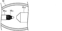
- FIG. 2 is an explanatory cross-sectional view showing a configuration of an example of a discharge lamp used in the discharge lamp lighting device shown in FIG.
- the discharge lamp 10 is a short arc type xenon discharge lamp.
- the arc tube 11 of the discharge lamp 10 is made of, for example, quartz glass. Further, the arc tube 11 extends outward along a tube axis that is integrally connected to each of the light emitting portion 12 having an outer shape that forms a discharge space therein and having a substantially elliptical spherical shape, and both ends of the light emitting portion 12.
- a cylindrical electrode support portion 13 and a sealing portion 14 having an outer diameter larger than the outer diameter of the electrode support portion 13 are integrally connected to the outer ends of the electrode support portions 13.
- An anode 15 and a cathode 16 made of a refractory metal such as tungsten are disposed in the light emitting portion 12 of the arc tube 11 so as to face each other. More specifically, the anode 15 is composed of an electrode rod 15b extending along the tube axis direction of the arc tube 11, and an anode body 15a provided at the tip of the electrode rod 15b.
- This anode main body 15a is comprised by the column-shaped trunk
- the cathode 16 includes a rod-shaped electrode bar 16b extending along the tube axis direction of the arc tube 11, and a cathode body 16a provided at the tip of the electrode bar 16b.
- the cathode body 16a is constituted by a columnar rear end portion and a substantially conical tip end portion.
- the anode body 15a and the cathode body 16a face each other, and the electrode bars 15b and 16b protrude from both ends of the arc tube 11 through the electrode support portion 13 and the sealing portion 14, respectively.
- a cylindrical glass member 17 is provided on the peripheral surface of the electrode rods 15b, 16b at the portion located on the electrode support portion 13.
- the electrode rods 15 b and 16 b are supported by the electrode support portion 13 through the glass member 17.
- the distance between the anode 15 and the cathode 16 is, for example, 2 to 10 mm.
- the cathode body 16a is required to have a function of emitting electrons. For this reason, the cathode main body 16a contains an electron emitting material which is an emitter material that lowers the work function.
- the electron emitting substance contained in the cathode body 16a thorium oxide (ThO 2 ), barium oxide (BaO), strontium oxide (SrO), calcium oxide (CaO), or the like can be used.
- the thorium oxide has a high operating temperature (a temperature that functions as an emitter), and is therefore preferably contained in the entire cathode body 16a or only at the tip of the cathode body 16a.
- barium oxide, strontium oxide or calcium oxide is used as the electron emitting material, these electron emitting materials are preferably contained in the cathode body 16a because the operating temperature is low.
- the cathode body 16a has a carbon component.
- a configuration in which a tungsten carbide layer 16c is provided in the vicinity of the tip of the cathode main body 16a can be exemplified as shown in FIG.
- the position where such a tungsten carbide layer 16c is formed is preferably a position that is retracted by at least 2 mm along the axial direction from the tip surface of the cathode body 16a in the cathode 16.
- the thickness of the tungsten carbide layer 16c is preferably 15 to 100 ⁇ m.
- tungsten carbide (W 2 C or WC) having a low melting point is formed at the tip with a thickness of 15 ⁇ m or more, the melting amount of the tip of the cathode body 16a becomes excessive. Therefore, the tip diameter of the cathode body 16a is damaged in a short time, and the luminance is lowered.
- the inner surface of the arc tube 12 is blackened by evaporation of tungsten carbide (W 2 C or WC), and the intensity of the emitted light is reduced, so that the lamp life comes to an early stage. In order to avoid the occurrence of these problems, it is preferable not to form the tungsten carbide layer 16c at the tip of the cathode body 16a.
- a xenon gas is sealed as a luminescent gas in the light emitting portion 12 of the arc tube 11.
- the sealed pressure of xenon gas is, for example, 0.5 to 5.0 MPa in static pressure. Further, mercury is not enclosed in the light emitting unit 12. Further, since the so-called halogen cycle action is not used, halogen such as bromine is not enclosed.
- the rated current of the discharge lamp 10 is, for example, 25 to 175 A, the rated voltage is, for example, 20 to 45 V, and the rated power is, for example, 1 to 8 kW.
- the lighting circuit 20 in the illustrated example is based on a so-called switching method.
- the lighting circuit 20 includes a soft start circuit 21, a first rectifying / smoothing circuit 22, an inverter circuit 23, a transformer circuit 24, a second rectifying / smoothing circuit 25, and an igniter 26. .
- the soft start circuit 21 reduces the inrush current when the discharge lamp 10 is turned on.
- the soft start circuit 21 includes a resistor R composed of a resistance element and a fuse, and a switching element S that is activated by a command signal from the control unit 50.
- the first rectifying / smoothing circuit 22 converts AC power from the soft start circuit 21 into DC power, and smoothes the DC power.
- the first rectifying / smoothing circuit 22 includes a bridge circuit including four rectifying diodes D1 to D4, and a capacitor C1.
- the inverter circuit 23 converts the DC power from the first rectifying / smoothing circuit 21 into high-frequency power of 20 to 1000 kHz, for example.
- the inverter circuit 23 has a bridge circuit including four switching elements S1 to S4 that are operated by, for example, a pulse width control signal from the control unit 50.
- the transformer circuit 24 transforms the voltage of the high frequency power input from the inverter circuit 23 to the primary side into a voltage suitable for lighting the discharge lamp 10 and outputs the voltage from the secondary side.
- the second rectifying / smoothing circuit 25 changes the high-frequency power output from the secondary side of the transformer circuit 24 to DC power, and smoothes the DC power.
- the second rectifying / smoothing circuit 25 includes two rectifying diodes D5 and D6, an inductor L1, and a capacitor C2.
- the igniter 26 is for applying a high voltage only when the discharge lamp 10 is turned on.
- the control unit 50 includes a control circuit that controls the lighting circuit 20 and performs a short-time lighting operation in which the discharge lamp 10 is lit at least once for a short period of time during which the discharge lamp 10 is not steadily lit. It has a time lighting circuit.
- the igniter 26 in the lighting circuit 20 when the igniter 26 in the lighting circuit 20 operates, a high voltage is applied between the anode 15 and the cathode 16 of the discharge lamp 10 to cause dielectric breakdown. As a result, current starts to flow through the discharge lamp 10. After the dielectric breakdown occurs, the value of the lamp current flowing through the discharge lamp 10 rises, and shifts to arc discharge through glow discharge. When the lamp current reaches the peak value, the anode 15 and the cathode 16 rise to a sufficient temperature, and a stable arc discharge is formed. After that, when the required DC power is supplied from the lighting circuit 20, steady discharge of the discharge lamp 10 is achieved.
- the operation is performed at a predetermined timing.
- the short-time lighting operation of the discharge lamp 10 includes, for example, a single DC pulse wave or a single DC pulse wave group composed of one or a plurality of single pulse waves having one polarity due to a DC current applied to the discharge lamp 10. It is executed by being supplied.
- the DC single pulse wave forms a waveform due to a steep rise and fall of the lamp current.
- This DC single pulse wave is supplied to the discharge lamp 10 by the operation of the lighting circuit 20 and the control unit 50 in the same process as the steady lighting of the discharge lamp 10.
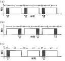
- FIG. 4 is a diagram showing a specific example of a predetermined timing at which a short-time lighting operation is performed in the discharge lamp lighting device of the present invention.
- L1, L2, and L3 are steady lighting periods during which the discharge lamp is steadily lit.
- P, P2, and P3 are rest periods during which the discharge lamp is not steadily lit.
- S, S2 and S3 are short-time lighting operation periods in which the short-time lighting operation is executed. The short-time lighting operation may be performed immediately before starting the steady lighting of the discharge lamp in the pause period as shown in FIG.
- the short-time lighting operation may be executed immediately after the stop of steady lighting, or may be executed at other timings in the rest period. Further, the short-time lighting operation does not have to be executed every pause period, and for example, as shown in FIG. 4C, the short-time lighting operation may be executed once per two pause periods. Further, the total lighting time of the discharge lamp 10 in the short-time lighting operation is, for example, 0.1 to 700 s, and preferably 0.1 to 100 s.
- the number of lighting in the short-time lighting operation (the number of DC single pulse waves supplied to the discharge lamp 10 in the short-time lighting operation) is 1 to 20 times (the number of DC single pulse waves is 1 to 20). It is preferable that When the number of times of lighting in the short-time lighting operation exceeds 20 times, the cathode 16 is severely worn and the luminance is lowered, or cracks are generated due to thermal shock to the anode 15, causing a short life. Or
- the lighting time of one short lighting in the short lighting operation is 0.1 to 5 seconds.
- the lighting time for one time is less than 0.1 seconds, the temperature of the cathode 16 does not rise sufficiently and the tip is not activated.
- the lighting time for one time exceeds 5 seconds, the tip of the activated cathode 16 advances in the inactive direction again, and it is not possible to obtain a sufficient lighting effect for a short time.
- the off time from the end of one short-time lighting to the start of the subsequent short-time lighting is 1 second or longer. More preferably, it is 5 to 30 seconds.
- the off time is less than 1 second, the temperature of the cathode 16 is not sufficiently lowered, and a sufficient thermal shock cannot be obtained at the next short-time lighting, so that an effect cannot be obtained.
- the short-time lighting operation for lighting the discharge lamp 10 for a short time is performed. Even when the discharge lamp 10 is lit for a long time, the occurrence of flicker in the discharge lamp 10 can be suppressed, and a long flicker life can be obtained.
- the surface shape of the cathode body 16a is rough and rough.
- the surface of the cathode body 16a is melted by the heat generated by the lighting and becomes a smooth shape.
- the surface of the cathode body 16a is restored to a smooth shape, so that a smooth and quick start operation is performed when the discharge lamp 10 is turned on.
- the tip of the cathode body 16a is less likely to be worn, and it is considered that the occurrence of flicker is suppressed.
- the cathode body 16a contains a carbon component by the tungsten carbide layer 16c and the like.
- tungsten carbide has a function of reducing an oxide emitter to form an emitter.
- the carbon used in the reduction is combined with oxygen in the oxide emitter to form carbon monoxide or carbon dioxide, which is supplied into the lamp.
- the carbon monoxide or carbon dioxide is scattered in the discharge arc, it is decomposed into plasma and becomes carbon ions. Since the carbon ions are cations, they are attracted to the cathode 16 side, collide with the surface of the cathode body 16a, and are deposited again as tungsten carbide.
- tungsten carbide deposited on the surface of the cathode body 16a has a lower melting point than that of normal tungsten, it is easily melted by the heat generated by lighting even for a short time. Therefore, it is considered that tungsten carbide that is easily melted is melted by lighting for a short time, and the action (1) is assisted.
- the emitter disappears from the surface of the cathode body 16a.
- the electron emitting material is reduced by the heat generated by the lighting, and the surface of the cathode body 16a.
- the emitter is supplied to the surface of the cathode body 16a, so that a smooth and quick start operation is performed. As a result, the tip of the cathode body 16a is less likely to be worn, and it is considered that the occurrence of flicker is suppressed.
- the discharge lamp lighting device of this invention was described, this invention is not limited to said embodiment, A various change can be added.
- the lighting circuit is not limited to that shown in FIG. 1, and various configurations can be adopted.
- a discharge lamp (short arc type xenon discharge lamp) having the following specifications was manufactured according to the configuration shown in FIG. 2, and a discharge lamp lighting device was manufactured according to the configuration shown in FIG. 1 using this discharge lamp.
- the arc tube is made of quartz glass, the maximum outer diameter of the light emitting part is 42 mm, and the inner volume of the light emitting part is 40 mm 3 .
- Each of an anode and a cathode is a product made from tungsten, and the distance between electrodes is 3.0 mm.
- the entire cathode body contains thorium oxide as an electron emitting substance.
- a tungsten carbide layer is provided near the tip of the cathode body.
- the position where the tungsten carbide layer is formed is a position which is receded by 2 mm along the axial direction from the front end face of the cathode body, and the thickness of the tungsten carbide layer is 30 ⁇ m.
- xenon gas Of xenon gas. -The rated current of the discharge lamp is 75 A, the rated voltage is 24 V, and the rated power is 1.8 kW.
- Example 2 Using the discharge lamp lighting device having the same configuration as in Experimental Example 1, the discharge lamp is steadily turned on under the following condition (1), and shortly under the condition (2) immediately after stopping the steady lighting in the rest period. A time lighting operation was performed (see FIG. 4B).
- a discharge lamp having the following specifications was manufactured according to the configuration shown in FIG. 2, and a discharge lamp lighting device was manufactured using these discharge lamps according to the configuration shown in FIG. Specifications of discharge lamp:
- the arc tube is made of quartz glass, the maximum outer diameter of the light emitting part is 42 mm, and the inner volume of the light emitting part is 40 mm 3 .
- Each of an anode and a cathode is a product made from tungsten, and the distance between electrodes is 3.0 mm.
- the entire cathode body contains thorium oxide as an electron emitting substance.
- a tungsten carbide layer is provided near the tip of the cathode body.
- the position where the tungsten carbide layer is formed is a position retracted 2 mm along the axial direction from the tip surface of the cathode body, and the thickness of the tungsten carbide layer is 30 ⁇ m.
- xenon gas Of xenon gas. -The rated current of the discharge lamp is 75 A, the rated voltage is 24 V, and the rated power is 1.8 kW.
- Example 4 The discharge lamp was steadily turned on and operated for a short time in the same manner as in Experimental Example 3 except that the discharge lamp was changed to one having the following specifications. Then, the amplitude of the lamp voltage when the total lighting time of the discharge lamp passed 250 hours was measured, and the relationship between the amplitude of the lamp voltage and the number of lighting times of short-time lighting was examined. The results are shown in FIG. Specifications of discharge lamp:
- the arc tube is made of quartz glass, the maximum outer diameter of the light emitting part is 42 mm, and the inner volume of the light emitting part is 40 mm 3 .
- Each of an anode and a cathode is a product made from tungsten, and the distance between electrodes is 3.7 mm.
- the entire cathode body contains thorium oxide as an electron emitting substance.
- a tungsten carbide layer is provided near the tip of the cathode body. The position where the tungsten carbide layer is formed is a position retracted 2 mm along the axial direction from the tip surface of the cathode body, and the thickness of the tungsten carbide layer is 30 ⁇ m.
Landscapes
- Circuit Arrangements For Discharge Lamps (AREA)
Abstract
放電ランプを長時間点灯させた場合でも、フリッカーの発生を抑制することができ、長いフリッカー寿命が得られる放電ランプ点灯装置を提供する。 発光管と、この発光管内に互いに対向して配置された陽極および陰極と、前記発光管内に封入されたキセノンガスとを有し、前記陰極は、電子放射物質を有すると共に、炭素成分を有するショートアーク型の放電ランプ、この放電ランプに電力を供給する点灯回路、並びにこの点灯回路を制御する制御部を備えてなる放電ランプ点灯装置であって、前記制御部は、前記放電ランプが定常点灯していない休止期間において、当該放電ランプを少なくとも1回以上短時間点灯させる短時間点灯動作を行う短時間点灯回路を有することを特徴とする。
Description
本発明は、放電ランプ点灯装置に関する。特に、映画館において映写機用光源として用いられる放電ランプ点灯装置に関する。
近年、映画館においては、フィルム映写機からデジタル映写機への置き換えが急速に進められている。そして、フィルム映写機およびデジタル映写機のいずれにおいても、光源としてショートアーク型キセノン放電ランプ等の放電ランプが広く用いられている。然るに、フィルム映写機とデジタル映写機とでは、放電ランプに求められる輝度が異なっている。具体的に説明すると、デジタル映写機においては、インテグレーターロッドの端面に集光するにあたり、フィルム映写機と比較してより狭い範囲に集光することが必要である。このため、デジタル映写機用の放電ランプにおいては、より短くて細いアークを形成するために、希ガス(キセノン)が、フィルム映写機用の放電ランプよりも相当に高い圧力で封入されている。
このような放電ランプを備えた放電ランプ点灯装置としては、点灯開始時に放電ランプに供給される電流を制御する制御部を備えてなるもの(特許文献1参照。)、放電ランプに供給される電流を変化させることによって放電ランプを調光する制御部を備えてなるもの(特許文献2参照。)などが知られている。
このような放電ランプを備えた放電ランプ点灯装置としては、点灯開始時に放電ランプに供給される電流を制御する制御部を備えてなるもの(特許文献1参照。)、放電ランプに供給される電流を変化させることによって放電ランプを調光する制御部を備えてなるもの(特許文献2参照。)などが知られている。
ところで、キセノン放電ランプにおいては、例えば点灯時間が経過するに伴って陰極が変形することによって、フリッカーが生ずる。そして、放電ランプの使用開始からフリッカーが頻繁に発生するに到るまでの時間は、フリッカー寿命と呼ばれている。
従来、長いフリッカー寿命が得られるキセノン放電ランプとしては、先端面に、タングステン相中に縞状のタングステン炭化物相が形成された表層を有する陰極を備えてなるものが提案されている(特許文献3参照。)。
従来、長いフリッカー寿命が得られるキセノン放電ランプとしては、先端面に、タングステン相中に縞状のタングステン炭化物相が形成された表層を有する陰極を備えてなるものが提案されている(特許文献3参照。)。
映画館においては、デジタル映写機の普及により、専門的な特殊技能を有する映写技師以外の者であっても映写機の操作が可能となる。また、映画本編だけではなく広告など様々なフォーマットも再生可能であることから、一日の上映時間が長くなっている。そして、これに伴って、光源である放電ランプも長時間連続して点灯されるようになっている。このため、デジタル映写機の光源としては、フリッカー寿命が一層長い放電ランプが望まれている。
本発明は、以上のような事情に基づいてなされたものであって、その目的は、放電ランプを長時間点灯させた場合でも、フリッカーの発生を抑制することができ、長いフリッカー寿命が得られる放電ランプ点灯装置を提供することにある。
本発明の放電ランプ点灯装置は、発光管と、この発光管内に互いに対向して配置された陽極および陰極と、前記発光管内に封入されたキセノンガスとを有し、前記陰極は、電子放射物質を有すると共に、炭素成分を有するショートアーク型の放電ランプ、
この放電ランプに電力を供給する点灯回路、並びに
この点灯回路を制御する制御部
を備えてなる放電ランプ点灯装置であって、
前記制御部は、前記放電ランプが定常点灯していない休止期間において、当該放電ランプを少なくとも1回以上短時間点灯させる短時間点灯動作を行う短時間点灯回路を有することを特徴とする。
この放電ランプに電力を供給する点灯回路、並びに
この点灯回路を制御する制御部
を備えてなる放電ランプ点灯装置であって、
前記制御部は、前記放電ランプが定常点灯していない休止期間において、当該放電ランプを少なくとも1回以上短時間点灯させる短時間点灯動作を行う短時間点灯回路を有することを特徴とする。
本発明の放電ランプ点灯装置においては、前記短時間点灯動作における総点灯時間は0.1~700秒間であることが好ましい。
また、前記短時間点灯動作における点灯回数が1~20回であることが好ましい。
また、前記短時間点灯動作における1回の短時間点灯の点灯時間が0.1~5秒間であることが好ましい。
また、前記短時間点灯動作における点灯回数が2回以上である場合には、一の短時間点灯が終了してから後続の短時間点灯が開始するまでのオフ時間が1秒間以上であることが好ましい。
また、前記短時間点灯動作における点灯回数が1~20回であることが好ましい。
また、前記短時間点灯動作における1回の短時間点灯の点灯時間が0.1~5秒間であることが好ましい。
また、前記短時間点灯動作における点灯回数が2回以上である場合には、一の短時間点灯が終了してから後続の短時間点灯が開始するまでのオフ時間が1秒間以上であることが好ましい。
本発明の放電ランプ点灯装置によれば、制御部における短時間点灯回路によって、放電ランプが定常点灯していない休止期間において、放電ランプを短時間点灯させる短時間点灯動作が行われることにより、放電ランプを長時間点灯させた場合でも、フリッカーの発生を抑制することができ、長いフリッカー寿命が得られる。
以下、本発明の放電ランプ点灯装置の実施の形態について説明する。
図1は、本発明の放電ランプ点灯装置の一例における構成の概略を示す説明図である。図1に示す放電ランプ点灯装置は、例えば映画館においてデジタル映写機用の光源として用いられるものである。この放電ランプ点灯装置は、放電ランプ10と、この放電ランプ10に電力を供給する点灯回路20と、この点灯回路20を制御する制御部50とを備えてなる。
図1は、本発明の放電ランプ点灯装置の一例における構成の概略を示す説明図である。図1に示す放電ランプ点灯装置は、例えば映画館においてデジタル映写機用の光源として用いられるものである。この放電ランプ点灯装置は、放電ランプ10と、この放電ランプ10に電力を供給する点灯回路20と、この点灯回路20を制御する制御部50とを備えてなる。
図2は、図1に示す放電ランプ点灯装置に用いられる放電ランプの一例における構成を示す説明用断面図である。
この放電ランプ10は、ショートアーク型キセノン放電ランプである。この放電ランプ10の発光管11は、例えば石英ガラスにより構成されている。また、発光管11は、内部に放電空間を形成する外形が略楕円球状の発光部12と、この発光部12の両端の各々に一体に連設された、管軸に沿って外方に伸びる円筒状の電極支持部13と、電極支持部13の各々の外端に一体に連接された、電極支持部13の外径より大きい外径の封止部14とを有する。
この放電ランプ10は、ショートアーク型キセノン放電ランプである。この放電ランプ10の発光管11は、例えば石英ガラスにより構成されている。また、発光管11は、内部に放電空間を形成する外形が略楕円球状の発光部12と、この発光部12の両端の各々に一体に連設された、管軸に沿って外方に伸びる円筒状の電極支持部13と、電極支持部13の各々の外端に一体に連接された、電極支持部13の外径より大きい外径の封止部14とを有する。
この発光管11における発光部12内には、それぞれ高融点金属例えばタングステンよりなる陽極15および陰極16が、互いに対向するよう配置されている。
具体的に説明すると、陽極15は、発光管11の管軸方向に沿って伸びる電極棒15bと、この電極棒15bの先端に設けられた陽極本体15aとにより構成されている。この陽極本体15aは、円柱状の胴部と円錐台状の先端部とによって構成されている。
一方、陰極16は、発光管11の管軸方向に沿って伸びる棒状の電極棒16bと、この電極棒16bの先端に設けられた陰極本体16aとにより構成されている。この陰極本体16aは、円柱状の後端部と略円錐状の先端部とにより構成されている。
そして、陽極15および陰極16は、陽極本体15aおよび陰極本体16aが互いに対向し、かつ、それぞれの電極棒15b,16bが電極支持部13および封止部14を介して発光管11の両端から突出するよう配置されている。また、電極棒15b,16bにおける電極支持部13に位置する部分の周面には、円筒状のガラス部材17が設けられている。このガラス部材17を介して電極棒15b,16bが電極支持部13に支持されている。
陽極15および陰極16間の距離(電極間距離)は、例えば2~10mmである。
具体的に説明すると、陽極15は、発光管11の管軸方向に沿って伸びる電極棒15bと、この電極棒15bの先端に設けられた陽極本体15aとにより構成されている。この陽極本体15aは、円柱状の胴部と円錐台状の先端部とによって構成されている。
一方、陰極16は、発光管11の管軸方向に沿って伸びる棒状の電極棒16bと、この電極棒16bの先端に設けられた陰極本体16aとにより構成されている。この陰極本体16aは、円柱状の後端部と略円錐状の先端部とにより構成されている。
そして、陽極15および陰極16は、陽極本体15aおよび陰極本体16aが互いに対向し、かつ、それぞれの電極棒15b,16bが電極支持部13および封止部14を介して発光管11の両端から突出するよう配置されている。また、電極棒15b,16bにおける電極支持部13に位置する部分の周面には、円筒状のガラス部材17が設けられている。このガラス部材17を介して電極棒15b,16bが電極支持部13に支持されている。
陽極15および陰極16間の距離(電極間距離)は、例えば2~10mmである。
陰極本体16aには、電子を放出する機能が求められる。このため、陰極本体16aには、仕事関数を低下させるエミッタ材である電子放射物質が含有されている。陰極本体16aに含有される電子放射物質としては、酸化トリウム(ThO2 )、酸化バリウム(BaO)、酸化ストロンチウム(SrO)、酸化カルシウム(CaO)などを用いることができる。
電子放射物質として酸化トリウムを用いる場合には、当該酸化トリウムは、動作温度(エミッタとして機能する温度)が高いため、陰極本体16a全体或いは陰極本体16aにおける先端部のみに含有されていることが好ましい。
また、電子放射物質として酸化バリウム、酸化ストロンチウムまたは酸化カルシウムを用いる場合には、これらの電子放射物質は、動作温度が低いため、陰極本体16aの内部に含有されていることが好ましい。
電子放射物質として酸化トリウムを用いる場合には、当該酸化トリウムは、動作温度(エミッタとして機能する温度)が高いため、陰極本体16a全体或いは陰極本体16aにおける先端部のみに含有されていることが好ましい。
また、電子放射物質として酸化バリウム、酸化ストロンチウムまたは酸化カルシウムを用いる場合には、これらの電子放射物質は、動作温度が低いため、陰極本体16aの内部に含有されていることが好ましい。
陰極本体16aは炭素成分を有するものである。炭素成分を有する陰極本体16aの一形態としては、図3に示すように、陰極本体16aにおける先端の近傍に炭化タングステン層16cが設けられた構成を挙げることができる。このような炭化タングステン層16cが形成される位置は、陰極16における陰極本体16aの先端面から軸方向に沿って少なくとも2mm後退した位置であることが好ましい。また、炭化タングステン層16cの厚みは、15~100μmであることが好ましい。
融点の低い炭化タングステン(W2 C若しくはWC)を15μm以上の厚みで先端に形成したときには、陰極本体16aにおける先端部の溶融量が過大となる。そのため、陰極本体16aの先端径が短時間で損傷して輝度が低下する。或いは、炭化タングステン(W2 C若しくはWC)の蒸発によって発光管12の内表面が黒化し、放射光の強度が低下することにより、早期にランプの寿命が到来する。これらの問題が生じることを回避するために、陰極本体16aの先端には炭化タングステン層16cを形成しないことが好ましい。
融点の低い炭化タングステン(W2 C若しくはWC)を15μm以上の厚みで先端に形成したときには、陰極本体16aにおける先端部の溶融量が過大となる。そのため、陰極本体16aの先端径が短時間で損傷して輝度が低下する。或いは、炭化タングステン(W2 C若しくはWC)の蒸発によって発光管12の内表面が黒化し、放射光の強度が低下することにより、早期にランプの寿命が到来する。これらの問題が生じることを回避するために、陰極本体16aの先端には炭化タングステン層16cを形成しないことが好ましい。
発光管11における発光部12内には、発光ガスとしてキセノンガスが封入されている。キセノンガスの封入圧は、例えば静圧で0.5~5.0MPaである。また、発光部12内には、水銀が封入されていない。また、いわゆるハロゲンサイクル作用を利用しないものであるから、臭素等のハロゲンも封入されていない。
また、放電ランプ10の定格電流は、例えば25~175A、定格電圧は、例えば20~45V、定格電力は、例えば1~8kWである。
また、放電ランプ10の定格電流は、例えば25~175A、定格電圧は、例えば20~45V、定格電力は、例えば1~8kWである。
図示の例の点灯回路20は、いわゆるスイッチング方式によるものである。この点灯回路20は、ソフトスタート回路21と、第1の整流・平滑回路22と、インバータ回路23と、トランス回路24と、第2の整流・平滑回路25と、イグナイタ26とにより構成されている。
ソフトスタート回路21は、放電ランプ10の点灯時の突入電流を減少させるものである。このソフトスタート回路21は、抵抗素子およびヒューズよりなる抵抗器Rと、制御部50からの指令信号によって作動するスイッチング素子Sとを有する。
第1の整流・平滑回路22は、ソフトスタート回路21からの交流電力を直流電力に変換し、当該直流電力を平滑化するものである。この第1の整流・平滑回路22は、4つの整流ダイオードD1~D4よりなるブリッジ回路と、コンデンサC1とを有する。
インバータ回路23は、第1の整流・平滑回路21からの直流電力を、例えば20~1000kHzの高周波電力に変換するものである。このインバータ回路23は、制御部50からの例えばパルス幅制御信号等によって作動する4つのスイッチング素子S1~S4よりなるブリッジ回路を有する。
トランス回路24は、インバータ回路23から一次側に入力された高周波電力の電圧を放電ランプ10を点灯するために適した電圧に変圧して2次側から出力するものである。 第2の整流・平滑回路25は、トランス回路24の二次側から出力された高周波電力を直流電力に変化し、当該直流電力を平滑化するものである。この第2の整流・平滑回路25は、2つの整流ダイオードD5,D6と、インダクタL1と、コンデンサC2とを有する。
イグナイタ26は、放電ランプ10の点灯始動時にのみ高電圧を印加するためのものである。
ソフトスタート回路21は、放電ランプ10の点灯時の突入電流を減少させるものである。このソフトスタート回路21は、抵抗素子およびヒューズよりなる抵抗器Rと、制御部50からの指令信号によって作動するスイッチング素子Sとを有する。
第1の整流・平滑回路22は、ソフトスタート回路21からの交流電力を直流電力に変換し、当該直流電力を平滑化するものである。この第1の整流・平滑回路22は、4つの整流ダイオードD1~D4よりなるブリッジ回路と、コンデンサC1とを有する。
インバータ回路23は、第1の整流・平滑回路21からの直流電力を、例えば20~1000kHzの高周波電力に変換するものである。このインバータ回路23は、制御部50からの例えばパルス幅制御信号等によって作動する4つのスイッチング素子S1~S4よりなるブリッジ回路を有する。
トランス回路24は、インバータ回路23から一次側に入力された高周波電力の電圧を放電ランプ10を点灯するために適した電圧に変圧して2次側から出力するものである。 第2の整流・平滑回路25は、トランス回路24の二次側から出力された高周波電力を直流電力に変化し、当該直流電力を平滑化するものである。この第2の整流・平滑回路25は、2つの整流ダイオードD5,D6と、インダクタL1と、コンデンサC2とを有する。
イグナイタ26は、放電ランプ10の点灯始動時にのみ高電圧を印加するためのものである。
制御部50は、点灯回路20を制御する制御回路を有すると共に、放電ランプ10が定常点灯していない休止期間において、当該放電ランプ10を少なくとも1回以上短時間点灯させる短時間点灯動作を行う短時間点灯回路を有するものである。
本発明の放電ランプ点灯装置においては、点灯回路20におけるイグナイタ26が動作すると、高電圧が放電ランプ10の陽極15および陰極16の間に印加されて絶縁破壊が生じる。これにより、放電ランプ10に電流が流れ始める。
絶縁破壊が生じた後においては、放電ランプ10に流れるランプ電流の値が上昇し、グロー放電を経てアーク放電に移行する。そして、ランプ電流がピーク値まで達すると、陽極15および陰極16が十分な温度に上昇することにより、安定したアーク放電が形成される。その後、点灯回路20から所要の直流電力が供給されることにより、放電ランプ10の定常点灯が達成される。
絶縁破壊が生じた後においては、放電ランプ10に流れるランプ電流の値が上昇し、グロー放電を経てアーク放電に移行する。そして、ランプ電流がピーク値まで達すると、陽極15および陰極16が十分な温度に上昇することにより、安定したアーク放電が形成される。その後、点灯回路20から所要の直流電力が供給されることにより、放電ランプ10の定常点灯が達成される。
そして、本発明の放電ランプ点灯装置においては、制御部50の短時間点灯回路によって、放電ランプ10が定常点灯していない休止期間において、放電ランプ10を少なくとも1回以上短時間点灯させる短時間点灯動作が所定のタイミングで行われる。
放電ランプ10の短時間点灯動作は、例えば直流電流による一方の極性を有する単一パルス波の単数若しくは複数から構成される直流単一パルス波、若しくは直流単一パルス波群が、放電ランプ10に供給されることによって実行される。直流単一パルス波は、急峻なランプ電流の上昇、下降による波形を形成する。この直流単一パルス波は、点灯回路20および制御部50の動作によって、放電ランプ10定常点灯と同様のプロセスで放電ランプ10に供給される。
放電ランプ10の短時間点灯動作は、例えば直流電流による一方の極性を有する単一パルス波の単数若しくは複数から構成される直流単一パルス波、若しくは直流単一パルス波群が、放電ランプ10に供給されることによって実行される。直流単一パルス波は、急峻なランプ電流の上昇、下降による波形を形成する。この直流単一パルス波は、点灯回路20および制御部50の動作によって、放電ランプ10定常点灯と同様のプロセスで放電ランプ10に供給される。
以上において、短時間点灯動作が実行される所定のタイミングは、放電ランプ10が定常点灯していない休止期間内であれば、適宜設定することができる。
図4は、本発明の放電ランプ点灯装置における短時間点灯動作が実行される所定のタイミングの具体例を示す図である。図4において、L1、L2およびL3は、放電ランプが定常点灯されている定常点灯期間である。また、P、P2およびP3は放電ランプが定常点灯されていない休止期間である。また、S、S2およびS3は短時間点灯動作が実行される短時間点灯動作期間である。短時間点灯動作は、図4(a)に示すように、休止期間における放電ランプの定常点灯の始動直前に実行されてもよく、図4(b)に示すように、休止期間における放電ランプの定常点灯の停止直後に実行されてもよく、休止期間におけるその他のタイミングで実行されてもよい。また、短時間点灯動作は、休止期間毎に実行される必要はなく、例えば図4(c)に示すように、休止期間2回につき1回の短時間点灯動作が実行されてもよい。
また、短時間点灯動作における放電ランプ10の総点灯時間は、例えば0.1~700sであり、好ましくは0.1~100sである。
図4は、本発明の放電ランプ点灯装置における短時間点灯動作が実行される所定のタイミングの具体例を示す図である。図4において、L1、L2およびL3は、放電ランプが定常点灯されている定常点灯期間である。また、P、P2およびP3は放電ランプが定常点灯されていない休止期間である。また、S、S2およびS3は短時間点灯動作が実行される短時間点灯動作期間である。短時間点灯動作は、図4(a)に示すように、休止期間における放電ランプの定常点灯の始動直前に実行されてもよく、図4(b)に示すように、休止期間における放電ランプの定常点灯の停止直後に実行されてもよく、休止期間におけるその他のタイミングで実行されてもよい。また、短時間点灯動作は、休止期間毎に実行される必要はなく、例えば図4(c)に示すように、休止期間2回につき1回の短時間点灯動作が実行されてもよい。
また、短時間点灯動作における放電ランプ10の総点灯時間は、例えば0.1~700sであり、好ましくは0.1~100sである。
また、短時間点灯動作における点灯回数(短時間点灯動作において放電ランプ10に供給される直流単一パルス波の数)は、1~20回(直流単一パルス波の数が1~20個)であることが好ましい。短時間点灯動作における点灯回数が20回を超える場合には、陰極16の損耗が激しくなって輝度の低下が発生したり、陽極15への熱衝撃によってクラックが発生して短寿命の原因になったりする。
また、短時間点灯動作における1回の短時間点灯の点灯時間(放電ランプ10に供給される直流単一パルス波の時間的長さ)は、0.1~5秒間であることが好ましい。1回の点灯時間が0.1秒間未満である場合には、陰極16の温度が十分に上昇せずに先端の活性化がなされない。一方、1回の点灯時間が5秒間を超える場合には、活性化された陰極16の先端が改めて非活性の方向に進み、十分な短時間点灯の効果を得ることができない。
また、短時間点灯動作における点灯回数が2回以上である場合には、一の短時間点灯が終了してから後続の短時間点灯が開始するまでのオフ時間が1秒間以上であることが好ましく、より好ましくは5~30秒間である。このオフ時間が1秒間未満である場合には、陰極16の温度が十分に下がりきらず、次の短時間点灯時に十分な熱衝撃が得られず、効果が得られない。
このような放電ランプ点灯装置によれば、制御部50における短時間点灯回路によって、放電ランプ10が定常点灯していないときに、放電ランプ10を短時間点灯させる短時間点灯動作が行われることにより、放電ランプ10を長時間点灯させた場合でも、放電ランプ10のフリッカーの発生を抑制することができ、長いフリッカー寿命が得られる。
本発明の放電ランプ点灯装置において、放電ランプ10のフリッカーの発生が抑制されて長いフリッカー寿命が得られる理由は定かではないが、例えば以下のように推測される。
(1)放電ランプ10の消灯直後においては、陰極本体16aの表面形状は粗く荒れた状態である。そして、放電ランプ10に対して短時間点灯動作を行うと、点灯による熱によって陰極本体16aの表面が溶融して滑らかな形状となる。このように、陰極本体16aの表面が滑らかな形状に修復されることにより、放電ランプ10の点灯始動時において、円滑で速やかな始動オペレーションが行われる。これにより、陰極本体16aの先端が損耗しにくくなるので、フリッカーの発生が抑制される、と考えられる。
(2)陰極本体16aには、炭化タングステン層16cなどによって炭素成分が含有されている。例えば炭化タングステンは、酸化物エミッタを還元して、エミッタとする機能を有する。そして、還元に使用された炭素は酸化物エミッタの酸素と結合し一酸化炭素もしくは二酸化炭素となりランプ中に供給される。この一酸化炭素もしくは二酸化炭素が放電アーク中に飛散すると、プラズマ中で分解されて炭素イオンとなる。この炭素イオンは陽イオンであるために陰極16側に引き寄せられて、陰極本体16aの表面に衝突し、再び炭化タングステンとして堆積することとなる。ここで、陰極本体16aの表面に堆積した炭化タングステンは、通常のタングステンよりも融点が低いため、短時間の点灯であっても、点灯による熱によって溶融しやすい。従って、溶融しやすい炭化タングステンが短時間点灯によって溶融し、上記(1)の作用が補助されている、と考えられる。
(3)放電ランプ10の消灯後においては、陰極本体16aの表面からエミッタが消失しているが、短時間点灯を行うと、点灯による熱によって、電子放射物質が還元され、陰極本体16aの表面に供給される。そして、放電ランプ10の点灯始動時においては、陰極本体16aの表面にエミッタが供給されていることにより、円滑で速やかな始動オペレーションが行われる。これにより、陰極本体16aの先端が損耗しにくくなるので、フリッカーの発生が抑制される、と考えられる。
以上、本発明の放電ランプ点灯装置の実施の形態について説明したが、本発明は、上記の実施の形態に限定されず、種々の変更を加えることが可能である。
例えば点灯回路は、図1に示すものに限定されず、種々の構成のものを採用することができる。
例えば点灯回路は、図1に示すものに限定されず、種々の構成のものを採用することができる。
〈実験例1〉
図2に示す構成に従い、下記の仕様の放電ランプ(ショートアーク型キセノン放電ランプ)を作製し、この放電ランプを用い、図1に示す構成に従って放電ランプ点灯装置を作製した。
放電ランプの仕様:
・発光管は石英ガラス製で、発光部の最大外径が42mm、発光部の内容積が40mm3 である。
・陽極および陰極の各々はタングステン製で、電極間距離が3.0mmである。
・陰極本体全体には、電子放射物質として酸化トリウムが含有されている。
・陰極本体における先端の近傍に炭化タングステン層が設けられている。この炭化タングステン層が形成れた位置は、陰極本体の先端面から軸方向に沿って2mm後退した位置であり、炭化タングステン層の厚みは30μmである
・発光管内には、静圧で1.6MPaのキセノンガスが封入されている。
・放電ランプの定格電流は75A、定格電圧は24V、定格電力は1.8kWである。
図2に示す構成に従い、下記の仕様の放電ランプ(ショートアーク型キセノン放電ランプ)を作製し、この放電ランプを用い、図1に示す構成に従って放電ランプ点灯装置を作製した。
放電ランプの仕様:
・発光管は石英ガラス製で、発光部の最大外径が42mm、発光部の内容積が40mm3 である。
・陽極および陰極の各々はタングステン製で、電極間距離が3.0mmである。
・陰極本体全体には、電子放射物質として酸化トリウムが含有されている。
・陰極本体における先端の近傍に炭化タングステン層が設けられている。この炭化タングステン層が形成れた位置は、陰極本体の先端面から軸方向に沿って2mm後退した位置であり、炭化タングステン層の厚みは30μmである
・発光管内には、静圧で1.6MPaのキセノンガスが封入されている。
・放電ランプの定格電流は75A、定格電圧は24V、定格電力は1.8kWである。
上記の放電ランプ点灯装置を用い、下記(1)の条件で放電ランプの定常点灯を繰り返し行うと共に、休止期間において定常点灯の始動直前に、下記(2)の条件で短時間点灯動作を行った(図4(a)参照。)。
(1)定常点灯条件
定常点灯期間=2時間
休止期間=30分間
(2)短時間点灯動作条件
1回の短時間点灯の点灯時間(直流単一パルス波の時間的長さ)=1秒間
短時間点灯の点灯回数=5回(直流単一パルス波の数=5個)
短時間点灯の総点灯時間=5秒間
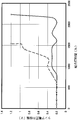
一の短時間点灯が終了してから後続の短時間点灯が開始するまでのオフ時間=15秒間 そして、放電ランプにフリッカーが生じると、ランプ電圧の振幅(ランプ電圧の短時間の変動値)が大きくなることから、ランプ電圧の振幅と放電ランプの総点灯時間との関係を調べた。結果を実線にて図5に示す。
また、ランプ電圧の振幅が1.2V以上となるまでの総点灯時間をフリッカー寿命として測定した。その結果、放電ランプのフリッカー寿命は、2200時間であった。
(1)定常点灯条件
定常点灯期間=2時間
休止期間=30分間
(2)短時間点灯動作条件
1回の短時間点灯の点灯時間(直流単一パルス波の時間的長さ)=1秒間
短時間点灯の点灯回数=5回(直流単一パルス波の数=5個)
短時間点灯の総点灯時間=5秒間
一の短時間点灯が終了してから後続の短時間点灯が開始するまでのオフ時間=15秒間 そして、放電ランプにフリッカーが生じると、ランプ電圧の振幅(ランプ電圧の短時間の変動値)が大きくなることから、ランプ電圧の振幅と放電ランプの総点灯時間との関係を調べた。結果を実線にて図5に示す。
また、ランプ電圧の振幅が1.2V以上となるまでの総点灯時間をフリッカー寿命として測定した。その結果、放電ランプのフリッカー寿命は、2200時間であった。
〈比較実験例1〉
短時間点灯動作を行わなかったこと以外は、実験例1と同様の条件で放電ランプを定常点灯させ、ランプ電圧の振幅と放電ランプの総点灯時間との関係を調べた。結果を点線にて図5に示す。
また、実験例1と同様にして放電ランプのフリッカー寿命を測定した。その結果、放電ランプのフリッカー寿命は、1500時間であった。
短時間点灯動作を行わなかったこと以外は、実験例1と同様の条件で放電ランプを定常点灯させ、ランプ電圧の振幅と放電ランプの総点灯時間との関係を調べた。結果を点線にて図5に示す。
また、実験例1と同様にして放電ランプのフリッカー寿命を測定した。その結果、放電ランプのフリッカー寿命は、1500時間であった。
〈実験例2〉
実験例1と同様の構成の放電ランプ点灯装置を用い、下記(1)の条件で放電ランプの定常点灯を繰り返し行うと共に、休止期間において定常点灯の停止直後に、下記(2)の条件で短時間点灯動作を行った(図4(b)参照。)。
(1)定常点灯条件
定常点灯期間=2時間
休止期間=30分間
(2)短時間点灯動作条件
1回の短時間点灯の点灯時間(直流単一パルス波の時間的長さ)=1秒間
短時間点灯の点灯回数=5回(直流単一パルス波の数が5個)
短時間点灯の総点灯時間=5秒間
一の短時間点灯が終了してから後続の短時間点灯が開始するまでのオフ時間=15秒間 そして、放電ランプにフリッカーが生じると、ランプ電圧の振幅(ランプ電圧の短時間の変動値)が大きくなることから、ランプ電圧の振幅と放電ランプの総点灯時間との関係を調べた。結果を実線にて図6に示す。
また、ランプ電圧の振幅が1.2V以上となるまでの総点灯時間をフリッカー寿命として測定した。その結果、放電ランプのフリッカー寿命は、2200時間であった。
実験例1と同様の構成の放電ランプ点灯装置を用い、下記(1)の条件で放電ランプの定常点灯を繰り返し行うと共に、休止期間において定常点灯の停止直後に、下記(2)の条件で短時間点灯動作を行った(図4(b)参照。)。
(1)定常点灯条件
定常点灯期間=2時間
休止期間=30分間
(2)短時間点灯動作条件
1回の短時間点灯の点灯時間(直流単一パルス波の時間的長さ)=1秒間
短時間点灯の点灯回数=5回(直流単一パルス波の数が5個)
短時間点灯の総点灯時間=5秒間
一の短時間点灯が終了してから後続の短時間点灯が開始するまでのオフ時間=15秒間 そして、放電ランプにフリッカーが生じると、ランプ電圧の振幅(ランプ電圧の短時間の変動値)が大きくなることから、ランプ電圧の振幅と放電ランプの総点灯時間との関係を調べた。結果を実線にて図6に示す。
また、ランプ電圧の振幅が1.2V以上となるまでの総点灯時間をフリッカー寿命として測定した。その結果、放電ランプのフリッカー寿命は、2200時間であった。
〈比較実験例2〉
短時間点灯動作を行わなかったこと以外は、実験例2と同様の条件で放電ランプを定常点灯させ、ランプ電圧の振幅と放電ランプの総点灯時間との関係を調べた。結果を点線にて図6に示す。
また、実験例2と同様にして放電ランプのフリッカー寿命を測定した。その結果、放電ランプのフリッカー寿命は、1300時間であった。
短時間点灯動作を行わなかったこと以外は、実験例2と同様の条件で放電ランプを定常点灯させ、ランプ電圧の振幅と放電ランプの総点灯時間との関係を調べた。結果を点線にて図6に示す。
また、実験例2と同様にして放電ランプのフリッカー寿命を測定した。その結果、放電ランプのフリッカー寿命は、1300時間であった。
以上の結果から明らかなように、放電ランプが定常点灯していないときに短時間点灯動作を行うことにより、放電ランプを長時間点灯させた場合でも、フリッカーの発生が抑制されて長いフリッカー寿命が得られることが確認された。
〈実験例3〉
図2に示す構成に従い、下記の仕様の放電ランプを作製し、これらの放電ランプを用い、図1に示す構成に従って放電ランプ点灯装置を作製した。
放電ランプの仕様:
・発光管は石英ガラス製で、発光部の最大外径が42mm、発光部の内容積が40mm3 である。
・陽極および陰極の各々はタングステン製で、電極間距離が3.0mmである。
・陰極本体全体には、電子放射物質として酸化トリウムが含有されている。
・陰極本体における先端の近傍に炭化タングステン層が設けられている。この炭化タングステン層が形成れた位置は、陰極本体の先端面から軸方向に沿って2mm後退した位置であり、炭化タングステン層の厚みは30μmである
・発光管内には、静圧で1.9MPaのキセノンガスが封入されている。
・放電ランプの定格電流は75A、定格電圧は24V、定格電力は1.8kWである。
図2に示す構成に従い、下記の仕様の放電ランプを作製し、これらの放電ランプを用い、図1に示す構成に従って放電ランプ点灯装置を作製した。
放電ランプの仕様:
・発光管は石英ガラス製で、発光部の最大外径が42mm、発光部の内容積が40mm3 である。
・陽極および陰極の各々はタングステン製で、電極間距離が3.0mmである。
・陰極本体全体には、電子放射物質として酸化トリウムが含有されている。
・陰極本体における先端の近傍に炭化タングステン層が設けられている。この炭化タングステン層が形成れた位置は、陰極本体の先端面から軸方向に沿って2mm後退した位置であり、炭化タングステン層の厚みは30μmである
・発光管内には、静圧で1.9MPaのキセノンガスが封入されている。
・放電ランプの定格電流は75A、定格電圧は24V、定格電力は1.8kWである。
上記の放電ランプ点灯装置を用い、下記(1)の条件で放電ランプの定常点灯を繰り返し行うと共に、休止期間において定常点灯の始動直前に、下記(2)の条件で短時間点灯動作を行った(図4(a)参照。)。
(1)定常点灯条件
定常点灯期間=2時間
休止期間=30分間
(2)短時間点灯動作条件
条件a:
短時間点灯動作なし
条件b:
1回の短時間点灯の点灯時間(直流単一パルス波の時間的長さ)=1秒間
短時間点灯の点灯回数=5回(直流単一パルス波の数が5個)
短時間点灯の総点灯時間=5秒間
一の短時間点灯が終了してから後続の短時間点灯が開始するまでのオフ時間=15秒間 条件c:
1回の短時間点灯の点灯時間(直流単一パルス波の時間的長さ)=1秒間
短時間点灯の点灯回数=20回(直流単一パルス波の数が20個)
短時間点灯の総点灯時間=20秒間
一の短時間点灯が終了してから後続の短時間点灯が開始するまでのオフ時間=15秒間 そして、放電ランプの総点灯時間が250時間経過したときのランプ電圧の振幅を測定し、ランプ電圧の振幅と短時間点灯の点灯回数との関係を調べた。結果を図7に示す。
(1)定常点灯条件
定常点灯期間=2時間
休止期間=30分間
(2)短時間点灯動作条件
条件a:
短時間点灯動作なし
条件b:
1回の短時間点灯の点灯時間(直流単一パルス波の時間的長さ)=1秒間
短時間点灯の点灯回数=5回(直流単一パルス波の数が5個)
短時間点灯の総点灯時間=5秒間
一の短時間点灯が終了してから後続の短時間点灯が開始するまでのオフ時間=15秒間 条件c:
1回の短時間点灯の点灯時間(直流単一パルス波の時間的長さ)=1秒間
短時間点灯の点灯回数=20回(直流単一パルス波の数が20個)
短時間点灯の総点灯時間=20秒間
一の短時間点灯が終了してから後続の短時間点灯が開始するまでのオフ時間=15秒間 そして、放電ランプの総点灯時間が250時間経過したときのランプ電圧の振幅を測定し、ランプ電圧の振幅と短時間点灯の点灯回数との関係を調べた。結果を図7に示す。
〈実験例4〉
放電ランプを下記の仕様のものに変更したこと以外は、実験例3と同様にして放電ランプの定常点灯および短時間点灯動作を行った。そして、放電ランプの総点灯時間が250時間経過したときのランプ電圧の振幅を測定し、ランプ電圧の振幅と短時間点灯の点灯回数との関係を調べた。結果を図7に示す。
放電ランプの仕様:
・発光管は石英ガラス製で、発光部の最大外径が42mm、発光部の内容積が40mm3 である。
・陽極および陰極の各々はタングステン製で、電極間距離が3.7mmである。
・陰極本体全体には、電子放射物質として酸化トリウムが含有されている。
・陰極本体における先端の近傍に炭化タングステン層が設けられている。この炭化タングステン層が形成れた位置は、陰極本体の先端面から軸方向に沿って2mm後退した位置であり、炭化タングステン層の厚みは30μmである
・発光管内には、静圧で1.9MPaのキセノンガスが封入されている。
・放電ランプの定格電流は75A、定格電圧は27V、定格電力は2.0kWである。
放電ランプを下記の仕様のものに変更したこと以外は、実験例3と同様にして放電ランプの定常点灯および短時間点灯動作を行った。そして、放電ランプの総点灯時間が250時間経過したときのランプ電圧の振幅を測定し、ランプ電圧の振幅と短時間点灯の点灯回数との関係を調べた。結果を図7に示す。
放電ランプの仕様:
・発光管は石英ガラス製で、発光部の最大外径が42mm、発光部の内容積が40mm3 である。
・陽極および陰極の各々はタングステン製で、電極間距離が3.7mmである。
・陰極本体全体には、電子放射物質として酸化トリウムが含有されている。
・陰極本体における先端の近傍に炭化タングステン層が設けられている。この炭化タングステン層が形成れた位置は、陰極本体の先端面から軸方向に沿って2mm後退した位置であり、炭化タングステン層の厚みは30μmである
・発光管内には、静圧で1.9MPaのキセノンガスが封入されている。
・放電ランプの定格電流は75A、定格電圧は27V、定格電力は2.0kWである。
図7の結果から明らかなように、短時間点灯の点灯回数が5~20回(条件bおよび条件c)であれば、ランプ電圧の振幅が低く、従って、フリッカーの発生が確実に抑制されることが確認された。
10 放電ランプ
11 発光管
12 発光部
13 電極支持部
14 封止部
15 陽極
15a 陽極本体
15b 電極棒
16 陰極
16a 陰極本体
16b 電極棒
16c 炭化タングステン層
17 ガラス部材
20 点灯回路
21 ソフトスタート回路
22 第1の整流・平滑回路
23 インバータ回路
24 トランス回路
25 第2の整流・平滑回路
26 イグナイタ
30 交流電源
50 制御部
C1,C2 コンデンサ
D1~D6 整流ダイオード
L1 インダクタ
R 抵抗器
S,S1~S4 スイッチング素子
11 発光管
12 発光部
13 電極支持部
14 封止部
15 陽極
15a 陽極本体
15b 電極棒
16 陰極
16a 陰極本体
16b 電極棒
16c 炭化タングステン層
17 ガラス部材
20 点灯回路
21 ソフトスタート回路
22 第1の整流・平滑回路
23 インバータ回路
24 トランス回路
25 第2の整流・平滑回路
26 イグナイタ
30 交流電源
50 制御部
C1,C2 コンデンサ
D1~D6 整流ダイオード
L1 インダクタ
R 抵抗器
S,S1~S4 スイッチング素子
Claims (5)
- 発光管と、この発光管内に互いに対向して配置された陽極および陰極と、前記発光管内に封入されたキセノンガスとを有し、前記陰極は、電子放射物質を有すると共に、炭素成分を有するショートアーク型の放電ランプ、
この放電ランプに電力を供給する点灯回路、並びに
この点灯回路を制御する制御部
を備えてなる放電ランプ点灯装置であって、
前記制御部は、前記放電ランプが定常点灯していない休止期間において、当該放電ランプを少なくとも1回以上短時間点灯させる短時間点灯動作を行う短時間点灯回路を有することを特徴とする放電ランプ点灯装置。 - 前記短時間点灯動作における総点灯時間は0.1~700秒間であることを特徴とする請求項1に記載の放電ランプ点灯装置。
- 前記短時間点灯動作における点灯回数が1~20回であることを特徴とする請求項1または請求項2に記載の放電ランプ点灯装置。
- 前記短時間点灯動作における1回の短時間点灯の点灯時間が0.1~5秒間であることを特徴とする請求項1乃至請求項3のいずれかに記載の放電ランプ点灯装置。
- 前記短時間点灯動作における点灯回数が2回以上であり、一の短時間点灯が終了してから後続の短時間点灯が開始するまでのオフ時間が1秒間以上であることを特徴とする請求項1乃至請求項4のいずれかに記載の放電ランプ点灯装置。
Priority Applications (3)
| Application Number | Priority Date | Filing Date | Title |
|---|---|---|---|
| EP13864913.2A EP2938168A4 (en) | 2012-12-21 | 2013-12-18 | LIGHTING DEVICE WITH A DISCHARGE LAMP |
| US14/650,728 US20160192462A1 (en) | 2012-12-21 | 2013-12-18 | Discharge lamp lighting device |
| CN201380063565.8A CN104838728B (zh) | 2012-12-21 | 2013-12-18 | 放电灯点灯装置 |
Applications Claiming Priority (2)
| Application Number | Priority Date | Filing Date | Title |
|---|---|---|---|
| JP2012279115A JP5811998B2 (ja) | 2012-12-21 | 2012-12-21 | 放電ランプ点灯装置 |
| JP2012-279115 | 2012-12-21 |
Publications (1)
| Publication Number | Publication Date |
|---|---|
| WO2014098127A1 true WO2014098127A1 (ja) | 2014-06-26 |
Family
ID=50978447
Family Applications (1)
| Application Number | Title | Priority Date | Filing Date |
|---|---|---|---|
| PCT/JP2013/083894 Ceased WO2014098127A1 (ja) | 2012-12-21 | 2013-12-18 | 放電ランプ点灯装置 |
Country Status (5)
| Country | Link |
|---|---|
| US (1) | US20160192462A1 (ja) |
| EP (1) | EP2938168A4 (ja) |
| JP (1) | JP5811998B2 (ja) |
| CN (1) | CN104838728B (ja) |
| WO (1) | WO2014098127A1 (ja) |
Cited By (2)
| Publication number | Priority date | Publication date | Assignee | Title |
|---|---|---|---|---|
| WO2016103694A1 (ja) * | 2014-12-25 | 2016-06-30 | ウシオ電機株式会社 | 放電ランプ点灯方法及び放電ランプ点灯装置 |
| JP2016122600A (ja) * | 2014-12-25 | 2016-07-07 | ウシオ電機株式会社 | 放電ランプ点灯方法及び放電ランプ点灯装置 |
Families Citing this family (2)
| Publication number | Priority date | Publication date | Assignee | Title |
|---|---|---|---|---|
| JP7134398B2 (ja) * | 2018-05-22 | 2022-09-12 | ウシオ電機株式会社 | 高圧放電ランプ |
| JP7765307B2 (ja) * | 2022-02-24 | 2025-11-06 | 株式会社オーク製作所 | 放電ランプ |
Citations (5)
| Publication number | Priority date | Publication date | Assignee | Title |
|---|---|---|---|---|
| JP2006210280A (ja) * | 2005-01-31 | 2006-08-10 | Sharp Corp | ランプユニット、及び投射型画像表示装置 |
| JP2010232023A (ja) * | 2009-03-27 | 2010-10-14 | Ushio Inc | ショートアーク型放電ランプ |
| JP2012022999A (ja) | 2010-07-17 | 2012-02-02 | Ushio Inc | キセノンランプ給電装置 |
| JP2012150951A (ja) | 2011-01-18 | 2012-08-09 | Ushio Inc | デジタルプロジェクター用のキセノンショートアークランプ |
| JP2012160387A (ja) | 2011-02-02 | 2012-08-23 | Ushio Inc | ランプ点灯装置 |
Family Cites Families (9)
| Publication number | Priority date | Publication date | Assignee | Title |
|---|---|---|---|---|
| JP3637779B2 (ja) * | 1998-07-24 | 2005-04-13 | ウシオ電機株式会社 | 誘電体バリア放電ランプ光源装置 |
| WO2003105542A1 (ja) * | 2002-06-07 | 2003-12-18 | 松下電器産業株式会社 | 無電極放電ランプ点灯装置、電球形無電極蛍光ランプおよび放電ランプ点灯装置 |
| EP1517590B1 (en) * | 2003-09-18 | 2009-12-30 | Toshiba Lighting & Technology Corporation | Starting unit for use in a high intensity discharge lamp lighting device |
| US7622869B2 (en) * | 2004-02-24 | 2009-11-24 | Panasonic Electric Works Co., Ltd. | Discharge lamp ballast and projector |
| JP2010108659A (ja) * | 2008-10-28 | 2010-05-13 | Panasonic Electric Works Co Ltd | 高圧放電灯点灯装置及びそれを用いた照明器具並びに照明システム |
| CN101873755B (zh) * | 2009-04-24 | 2014-04-16 | 松下电器产业株式会社 | 放电灯点灯装置及照明器具 |
| JP5299132B2 (ja) * | 2009-07-07 | 2013-09-25 | ウシオ電機株式会社 | デジタルプロジェクター用キセノンショートアークランプ |
| JP4983877B2 (ja) * | 2009-09-11 | 2012-07-25 | ウシオ電機株式会社 | 高圧放電ランプ点灯装置およびプロジェクタ |
| JP2012146578A (ja) * | 2011-01-13 | 2012-08-02 | Koito Mfg Co Ltd | 車両用放電バルブ |
-
2012
- 2012-12-21 JP JP2012279115A patent/JP5811998B2/ja not_active Expired - Fee Related
-
2013
- 2013-12-18 US US14/650,728 patent/US20160192462A1/en not_active Abandoned
- 2013-12-18 EP EP13864913.2A patent/EP2938168A4/en not_active Withdrawn
- 2013-12-18 CN CN201380063565.8A patent/CN104838728B/zh not_active Expired - Fee Related
- 2013-12-18 WO PCT/JP2013/083894 patent/WO2014098127A1/ja not_active Ceased
Patent Citations (5)
| Publication number | Priority date | Publication date | Assignee | Title |
|---|---|---|---|---|
| JP2006210280A (ja) * | 2005-01-31 | 2006-08-10 | Sharp Corp | ランプユニット、及び投射型画像表示装置 |
| JP2010232023A (ja) * | 2009-03-27 | 2010-10-14 | Ushio Inc | ショートアーク型放電ランプ |
| JP2012022999A (ja) | 2010-07-17 | 2012-02-02 | Ushio Inc | キセノンランプ給電装置 |
| JP2012150951A (ja) | 2011-01-18 | 2012-08-09 | Ushio Inc | デジタルプロジェクター用のキセノンショートアークランプ |
| JP2012160387A (ja) | 2011-02-02 | 2012-08-23 | Ushio Inc | ランプ点灯装置 |
Non-Patent Citations (1)
| Title |
|---|
| See also references of EP2938168A4 |
Cited By (2)
| Publication number | Priority date | Publication date | Assignee | Title |
|---|---|---|---|---|
| WO2016103694A1 (ja) * | 2014-12-25 | 2016-06-30 | ウシオ電機株式会社 | 放電ランプ点灯方法及び放電ランプ点灯装置 |
| JP2016122600A (ja) * | 2014-12-25 | 2016-07-07 | ウシオ電機株式会社 | 放電ランプ点灯方法及び放電ランプ点灯装置 |
Also Published As
| Publication number | Publication date |
|---|---|
| EP2938168A4 (en) | 2016-10-12 |
| EP2938168A1 (en) | 2015-10-28 |
| US20160192462A1 (en) | 2016-06-30 |
| CN104838728A (zh) | 2015-08-12 |
| CN104838728B (zh) | 2017-09-22 |
| JP2014123493A (ja) | 2014-07-03 |
| JP5811998B2 (ja) | 2015-11-11 |
Similar Documents
| Publication | Publication Date | Title |
|---|---|---|
| JP5193445B2 (ja) | 高圧放電灯点灯装置及び照明器具 | |
| CN1207753C (zh) | 高亮度放电灯以及高亮度放电灯点灯装置 | |
| CN100466877C (zh) | 用于高压放电灯的发光方法和装置以及高压放电灯装置 | |
| JP5811998B2 (ja) | 放電ランプ点灯装置 | |
| CN1577714A (zh) | 短弧型放电灯点灯装置 | |
| JP4345401B2 (ja) | 高圧水銀ランプ装置 | |
| JP2007213922A (ja) | 高圧放電ランプ点灯装置およびこれを用いた投射型ディスプレイ装置 | |
| JP4981424B2 (ja) | 高輝度放電ランプの瞬時高温再始動用の方法及び回路 | |
| JPWO2008041709A1 (ja) | 評価システム、点灯装置及び画像表示装置 | |
| JP4121758B2 (ja) | 高圧放電灯の直流点灯方法とその点灯装置 | |
| US9137881B2 (en) | Discharge lamp lighting apparatus | |
| CN101523542A (zh) | 评价系统、点灯装置以及图像显示装置 | |
| JP4650795B2 (ja) | 高圧放電灯点灯装置 | |
| JP4961724B2 (ja) | 放電ランプ点灯装置 | |
| JP2004342357A (ja) | 交流点灯方式の超高圧水銀ランプの点灯装置および点灯方法 | |
| JP2009211867A (ja) | 超高圧水銀ランプ | |
| JP2005032711A (ja) | 高圧放電ランプの点灯方法及び点灯装置、高圧放電ランプ装置、並びに投射型画像表示装置 | |
| JP5158185B2 (ja) | 放電ランプ点灯装置 | |
| KR100590812B1 (ko) | 메탈 할라이드 램프용 순시 점등형 전자식 안정기 | |
| JP2002352990A (ja) | 放電灯点灯装置 | |
| RU2422940C1 (ru) | Способ зажигания мощной газоразрядной лампы | |
| JP5010987B2 (ja) | 高圧放電ランプの点灯方法 | |
| JP2000208100A (ja) | 高圧水銀ランプ、およびその光源装置 | |
| KR200341363Y1 (ko) | 메탈 할라이드 램프용 순시 점등형 전자식 안정기 | |
| JP3072096U (ja) | 耐候光性試験装置 |
Legal Events
| Date | Code | Title | Description |
|---|---|---|---|
| 121 | Ep: the epo has been informed by wipo that ep was designated in this application |
Ref document number: 13864913 Country of ref document: EP Kind code of ref document: A1 |
|
| WWE | Wipo information: entry into national phase |
Ref document number: 14650728 Country of ref document: US |
|
| WWE | Wipo information: entry into national phase |
Ref document number: 2013864913 Country of ref document: EP |
|
| NENP | Non-entry into the national phase |
Ref country code: DE |