WO2014098236A1 - 車両 - Google Patents
車両 Download PDFInfo
- Publication number
- WO2014098236A1 WO2014098236A1 PCT/JP2013/084341 JP2013084341W WO2014098236A1 WO 2014098236 A1 WO2014098236 A1 WO 2014098236A1 JP 2013084341 W JP2013084341 W JP 2013084341W WO 2014098236 A1 WO2014098236 A1 WO 2014098236A1
- Authority
- WO
- WIPO (PCT)
- Prior art keywords
- vehicle
- body frame
- cross portion
- cross
- equipment
- Prior art date
- Legal status (The legal status is an assumption and is not a legal conclusion. Google has not performed a legal analysis and makes no representation as to the accuracy of the status listed.)
- Ceased
Links
Images






Classifications
-
- B—PERFORMING OPERATIONS; TRANSPORTING
- B62—LAND VEHICLES FOR TRAVELLING OTHERWISE THAN ON RAILS
- B62K—CYCLES; CYCLE FRAMES; CYCLE STEERING DEVICES; RIDER-OPERATED TERMINAL CONTROLS SPECIALLY ADAPTED FOR CYCLES; CYCLE AXLE SUSPENSIONS; CYCLE SIDECARS, FORECARS, OR THE LIKE
- B62K5/00—Cycles with handlebars, equipped with three or more main road wheels
- B62K5/10—Cycles with handlebars, equipped with three or more main road wheels with means for inwardly inclining the vehicle body on bends
-
- B—PERFORMING OPERATIONS; TRANSPORTING
- B62—LAND VEHICLES FOR TRAVELLING OTHERWISE THAN ON RAILS
- B62D—MOTOR VEHICLES; TRAILERS
- B62D9/00—Steering deflectable wheels not otherwise provided for
- B62D9/02—Steering deflectable wheels not otherwise provided for combined with means for inwardly inclining vehicle body on bends
-
- B—PERFORMING OPERATIONS; TRANSPORTING
- B62—LAND VEHICLES FOR TRAVELLING OTHERWISE THAN ON RAILS
- B62K—CYCLES; CYCLE FRAMES; CYCLE STEERING DEVICES; RIDER-OPERATED TERMINAL CONTROLS SPECIALLY ADAPTED FOR CYCLES; CYCLE AXLE SUSPENSIONS; CYCLE SIDECARS, FORECARS, OR THE LIKE
- B62K19/00—Cycle frames
- B62K19/30—Frame parts shaped to receive other cycle parts or accessories
- B62K19/38—Frame parts shaped to receive other cycle parts or accessories for attaching brake members
-
- B—PERFORMING OPERATIONS; TRANSPORTING
- B62—LAND VEHICLES FOR TRAVELLING OTHERWISE THAN ON RAILS
- B62K—CYCLES; CYCLE FRAMES; CYCLE STEERING DEVICES; RIDER-OPERATED TERMINAL CONTROLS SPECIALLY ADAPTED FOR CYCLES; CYCLE AXLE SUSPENSIONS; CYCLE SIDECARS, FORECARS, OR THE LIKE
- B62K25/00—Axle suspensions
- B62K25/04—Axle suspensions for mounting axles resiliently on cycle frame or fork
-
- B—PERFORMING OPERATIONS; TRANSPORTING
- B62—LAND VEHICLES FOR TRAVELLING OTHERWISE THAN ON RAILS
- B62K—CYCLES; CYCLE FRAMES; CYCLE STEERING DEVICES; RIDER-OPERATED TERMINAL CONTROLS SPECIALLY ADAPTED FOR CYCLES; CYCLE AXLE SUSPENSIONS; CYCLE SIDECARS, FORECARS, OR THE LIKE
- B62K5/00—Cycles with handlebars, equipped with three or more main road wheels
- B62K5/02—Tricycles
- B62K5/027—Motorcycles with three wheels
-
- B—PERFORMING OPERATIONS; TRANSPORTING
- B62—LAND VEHICLES FOR TRAVELLING OTHERWISE THAN ON RAILS
- B62K—CYCLES; CYCLE FRAMES; CYCLE STEERING DEVICES; RIDER-OPERATED TERMINAL CONTROLS SPECIALLY ADAPTED FOR CYCLES; CYCLE AXLE SUSPENSIONS; CYCLE SIDECARS, FORECARS, OR THE LIKE
- B62K5/00—Cycles with handlebars, equipped with three or more main road wheels
- B62K5/02—Tricycles
- B62K5/05—Tricycles characterised by a single rear wheel
-
- B—PERFORMING OPERATIONS; TRANSPORTING
- B62—LAND VEHICLES FOR TRAVELLING OTHERWISE THAN ON RAILS
- B62K—CYCLES; CYCLE FRAMES; CYCLE STEERING DEVICES; RIDER-OPERATED TERMINAL CONTROLS SPECIALLY ADAPTED FOR CYCLES; CYCLE AXLE SUSPENSIONS; CYCLE SIDECARS, FORECARS, OR THE LIKE
- B62K5/00—Cycles with handlebars, equipped with three or more main road wheels
- B62K5/08—Cycles with handlebars, equipped with three or more main road wheels with steering devices acting on two or more wheels
-
- B—PERFORMING OPERATIONS; TRANSPORTING
- B60—VEHICLES IN GENERAL
- B60G—VEHICLE SUSPENSION ARRANGEMENTS
- B60G2300/00—Indexing codes relating to the type of vehicle
- B60G2300/12—Cycles; Motorcycles
- B60G2300/122—Trikes
-
- B—PERFORMING OPERATIONS; TRANSPORTING
- B60—VEHICLES IN GENERAL
- B60G—VEHICLE SUSPENSION ARRANGEMENTS
- B60G2300/00—Indexing codes relating to the type of vehicle
- B60G2300/45—Rolling frame vehicles
-
- B—PERFORMING OPERATIONS; TRANSPORTING
- B62—LAND VEHICLES FOR TRAVELLING OTHERWISE THAN ON RAILS
- B62K—CYCLES; CYCLE FRAMES; CYCLE STEERING DEVICES; RIDER-OPERATED TERMINAL CONTROLS SPECIALLY ADAPTED FOR CYCLES; CYCLE AXLE SUSPENSIONS; CYCLE SIDECARS, FORECARS, OR THE LIKE
- B62K5/00—Cycles with handlebars, equipped with three or more main road wheels
- B62K2005/001—Suspension details for cycles with three or more main road wheels
Definitions
- the present invention relates to a vehicle having an inclined body frame and two front wheels.
- Non-Patent Document 1 Patent Document 1, and the like are known to have a vehicle body frame and two front wheels that are inclined.
- vehicle equipment such as a radiator and a headlight are arranged in front of the link mechanism.
- the link mechanism is arranged above the right front wheel and the left front wheel, not between the right front wheel and the left front wheel. With such a configuration, an increase in the distance in the left-right direction of the vehicle is suppressed.
- a vehicle having an inclined body frame and two front wheels as described in Non-Patent Document 1 has a large front portion of the vehicle. It has two front wheels, a right front wheel and a left front wheel that can be steered, and a link mechanism that supports the right front wheel and the left front wheel so that they can be displaced in the vertical direction of the body frame with respect to the body frame. caused by.
- the members constituting the link mechanism move greatly, and the right front wheel and the left front wheel are largely displaced with respect to the body frame.
- the vehicle exterior parts provided in the front part of the vehicle are enlarged in order to avoid interference with the link mechanism that is largely movable and the right front wheel and the left front wheel that are largely displaced.
- vehicle equipment such as headlights, turn signal lamps, front covers, and radiators are also arranged at the front of the vehicle. For this reason, in such a vehicle, the front part of the vehicle, which is above the two front wheels, tends to be large.
- FIG. 13 is a schematic diagram showing a vehicle body frame described in Non-Patent Document 1.
- vehicle equipment such as a vehicle body cover and a radiator is supported on the vehicle body frame 110 by the support member 100.
- the support member 100 includes an upper support member 101 extending forward from above the link mechanism 105 so as to avoid the link mechanism 105, and a lower support member 103 extending forward and downward from the upper support member 101.
- a vehicle body cover is attached to the upper support member 101.
- a radiator is attached to the lower support member 103.
- the present invention provides a vehicle having an inclined body frame and two front wheels, which can suppress an increase in size of the vehicle even when vehicle equipment is mounted.
- a cross portion that is rotatably supported about an axis, and an intermediate portion is supported by a link support portion that is a part of the vehicle body frame so as to be rotatable about an intermediate axis parallel to the right axis and the left axis.
- a link mechanism Vehicle equipment disposed in front of the vehicle body frame in the front-rear direction from the link mechanism,
- the cross part includes a front cross part positioned in front of the link support part of the body frame,
- the link mechanism is When viewed from the intermediate axis direction, the front cross portion has rotated relative to the vehicle body frame inward from the front movable outer edge, which is the outer edge of the locus formed when the front cross portion has rotated relative to the vehicle body frame. Sometimes it has a penetrating part that forms a space that does not overlap the front cross part,
- the vehicle equipment is It is supported by the vehicle body frame via an equipment support portion arranged in a space formed by the penetration portion.
- Non-Patent Document 1 or Patent Document 1 In a conventionally proposed vehicle having a body frame and two front wheels that are inclined as described in Non-Patent Document 1 or Patent Document 1, the front portion of the vehicle is large. Then, the support structure of the vehicle equipment of the vehicle provided with the vehicle body frame and the two front wheels which are inclined as described in Non-Patent Document 1 or Patent Document 1 proposed in the past has been investigated and analyzed.
- the vehicle of Non-Patent Document 1 or Patent Document 1 includes a cross portion of a link mechanism and vehicle equipment. The cross portion is always positioned inward from the movable outer edge, which is the outer edge of the locus formed by the cross portion when the cross portion is rotated as viewed from the intermediate axis direction.
- the equipment support portion that supports the vehicle equipment is formed in a shape that wraps outward from the movable outer edge of the cross portion when viewed from the intermediate axis direction.
- the vehicle of Non-Patent Document 1 or Patent Document 1 has an upper stay that extends from the body frame above the movable outer edge of the cross portion and extends forward of the link mechanism.
- the vehicle has a lower stay that extends from the body frame below the movable outer edge of the cross portion and extends forward of the link mechanism. Since the upper stay and the lower stay are arranged above and below the movable outer edge of the cross portion, it has been found that the front portion of the vehicle is enlarged.
- the distance between the vehicle equipment and the vehicle body frame is large, so that the upper stay and the lower stay become longer.
- the upper stay and the lower stay have been increased in size to ensure the rigidity to support the vehicle equipment. Therefore, the front part of the vehicle has become larger.
- the present inventors have devised a technical idea that the movable outer edge of the cross portion is not detoured in contrast to the conventional technical idea of bypassing the movable outer edge of the cross portion. This could be found for the first time by analyzing in detail the rotation of the cross member relative to the body frame. The movable outer edge of the cross part is large.
- the cross part is rotatably supported by the body frame.
- the cross portion includes a front cross portion positioned in front of the link support portion of the body frame. Therefore, if the interference with the front cross portion is avoided, it has been found that even if the vehicle equipment is arranged in the front portion of the vehicle, it is difficult to enlarge the front portion of the vehicle. Therefore, the idea was reversed, and the technical idea of supporting the inner side of the movable outer edge having a large cross portion, that is, the technical idea of not circumventing the movable outer edge of the cross portion was devised.
- the cross portion includes a front cross portion positioned in front of the link support portion of the body frame.
- the link mechanism When the front cross section rotates with respect to the vehicle body frame, the link mechanism is inward from the front movable outer edge, which is the outer edge of the locus formed when the front cross section rotates with respect to the vehicle body frame, as viewed from the intermediate axis direction. Has a through portion that forms a space that does not overlap the front cross portion.
- the vehicle equipment is supported by the vehicle body frame via an equipment support portion arranged in a space formed by the penetration portion. Therefore, even if the vehicle equipment is mounted on a vehicle having an inclined body frame and two front wheels, the increase in size of the vehicle can be suppressed.
- the penetration part may be located inward from the outer edge of the front cross part located in front of the link support part when viewed from the intermediate axis direction. According to the aspect of (2), since the penetration part was formed inward rather than the outer edge of the front cross part, the enlargement of the front movable outer edge of the front cross part can be further suppressed. Therefore, even if the vehicle equipment is mounted on a vehicle having an inclined body frame and two front wheels, the increase in size of the vehicle can be further suppressed.
- the penetrating portion may be closer to the intermediate axis than the left end portion and the right end portion of the front cross portion located in front of the link support portion.
- the size of the penetrating portion viewed from the intermediate axis direction can be reduced. For this reason, according to the aspect of (3), even if it mounts a vehicle accessory in the vehicle provided with the vehicle body frame which inclines and two front wheels, the enlargement of a vehicle can be suppressed more.
- the intermediate axis may be located in a space formed by the penetrating portion when viewed from the intermediate axis direction.
- the intermediate axis does not move or rotate with respect to the vehicle body frame even when the link mechanism operates.
- a penetration part can be formed in a required minimum magnitude
- the equipment support part may be a part of a rotation support part that rotatably supports the front cross part on the link support part.
- the equipment support portion can be configured using the portion that supports the front cross portion, it is possible to support the vehicle equipment with a simple configuration without providing a separate equipment support portion. . Therefore, even if the vehicle equipment is mounted on a vehicle having an inclined body frame and two front wheels, the increase in size of the vehicle can be further suppressed.
- the penetrating portion may form a long hole including an arc centered on the intermediate axis of the front cross portion.
- the penetration part forms an ellipse including an arc centered on the intermediate axis that is the center of rotation of the front cross part with respect to the body frame. For this reason, the shape of a penetration part can be made small, avoiding interference with the space which a penetration part forms, and an equipment support part. Therefore, even if the vehicle equipment is mounted on a vehicle having an inclined body frame and two front wheels, the increase in size of the vehicle can be further suppressed.
- the link mechanism includes a front upper cross portion positioned forward of the link support portion, a front lower cross portion whose intermediate axis is positioned lower than the front upper cross portion and positioned forward of the link support portion,
- the penetration portion may include an upper penetration portion that is a part of a lower edge of the front upper cross portion and a lower penetration portion that is a part of an upper edge of the front lower cross portion.
- an equipment support part can be provided using the clearance gap between a front upper cross part and a front lower cross part. For this reason, the utilization efficiency of the space of the vehicle front part increases. Therefore, even if the vehicle equipment is mounted on a vehicle having an inclined body frame and two front wheels, the increase in size of the vehicle can be further suppressed.
- the vehicle equipment may be supported by the link support portion of the body frame.
- the link support part supports the link mechanism that supports the right front wheel, the left front wheel, the right shock absorber, and the left shock absorber, and has high rigidity. Therefore, the configuration for supporting the vehicle equipment can be simplified by using the high rigidity to support the vehicle equipment. Therefore, even if the vehicle equipment is mounted on a vehicle having an inclined body frame and two front wheels, the increase in size of the vehicle can be further suppressed.
- a plurality of the penetrating portions are provided;
- a plurality of equipment support portions may be provided. According to the aspect of (9), it can support firmly by supporting a vehicle accessory in multiple places.
- Each equipment support portion can be formed small to facilitate avoiding interference with the link mechanism. Therefore, even if the vehicle equipment is mounted on a vehicle having an inclined body frame and two front wheels, the increase in size of the vehicle can be further suppressed.
- the vehicle equipment is further supported by the vehicle body frame via a connecting portion that is disposed outside the front movable outer edge without being disposed in a space formed by the through portion when viewed from the intermediate axis direction. Also good. According to the aspect of (10), it is easy to ensure the support rigidity of a vehicle equipment with an equipment support part and a connection part. Therefore, even if the vehicle equipment is mounted on a vehicle having an inclined body frame and two front wheels, the increase in size of the vehicle can be further suppressed.
- the equipment support portion may be at least a part of any one of the body frame, the vehicle equipment, and a mounting bracket for attaching the vehicle equipment to the body frame.
- an equipment support part can be simply constituted using other members. Therefore, even if the vehicle equipment is mounted on a vehicle having an inclined body frame and two front wheels, the increase in size of the vehicle can be further suppressed.
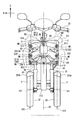
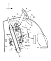
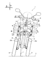
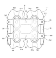
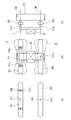
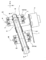
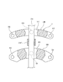
- FIG. 2 is an overall front view of the vehicle of FIG. 1 shown with a vehicle body cover removed. It is sectional drawing seen from the right side of the vehicle front part of the vehicle shown in FIG. It is a perspective view of a supporting member. It is a front view which shows a mounting bracket, a fluid unit, and a headlamp. It is a whole front view which shows the state which inclined the vehicle. It is a front view which shows the link mechanism and support member of a vehicle which concern on the 1st modification of this invention. It is a sectional side view which shows the link mechanism and equipment support part of the vehicle which concern on the 2nd modification of this invention.
- the arrow F in the figure indicates the forward direction of the vehicle 1.
- An arrow R in the figure indicates the right direction of the vehicle 1.
- Arrow U indicates the upward direction.
- the center in the vehicle width direction means the center position in the vehicle width direction of the vehicle in front view.
- the side in the vehicle width direction means a direction from the center in the vehicle width direction to the left or right.
- FIG. 1 is a schematic side view of the entire vehicle 1.
- the front, rear, left, and right directions indicate the front, rear, left, and right directions as viewed from the occupant driving the vehicle 1.
- the vehicle 1 includes a vehicle body 2, a front wheel 3 and a rear wheel 4.
- the vehicle body 2 is mainly composed of a vehicle body frame 21, a vehicle body cover 22, a handle 23, a seat 24, and a power unit 25.
- the vehicle body frame 21 supports the power unit 25, the seat 24, and the like.
- the power unit 25 includes a power source such as an engine or an electric motor, a mission device, and the like.
- the body frame 21 is indicated by a broken line.
- the body frame 21 includes a head pipe 211, a front frame 212, and a rear frame 213.
- the head pipe 211 is disposed at the front portion of the vehicle.
- a link mechanism 5 is disposed around the head pipe 211.
- the steering shaft 60 is rotatably inserted into the head pipe 211.
- the steering shaft 60 extends in the vertical direction. From the head pipe 211, the 1st penetration part 211a and the 2nd penetration part 211b protrude ahead so that the link mechanism 5 may be penetrated.
- the handle 23 is attached to the upper end of the steering shaft 60.
- the front frame 212 is inclined downward from the front end toward the rear.
- the rear frame 213 supports the seat 24 and the tail lamp.
- the vehicle body frame 21 is covered with a vehicle body cover 22.
- the vehicle body cover 22 includes a front cover 221, a front fender 223, and a rear fender 224.
- the front cover 221 is located in front of the seat 24.
- the front cover 221 covers the head pipe 211 and the link mechanism 5.
- the front fenders 223 are respectively disposed above the pair of left and right front wheels 3.
- the front fender 223 is disposed below the front cover 221.
- the rear fender 224 is disposed above the rear wheel 4.
- the front wheel 3 is located below the head pipe 211 and the link mechanism 5.
- the front wheel 3 is disposed below the front cover 221.
- FIG. 2 is an overall front view showing the vehicle 1 with the vehicle body cover 22 removed.
- the vehicle 1 includes a handle 23, a steering shaft 60, a head pipe 211, a pair of left and right front wheels 3, and a link mechanism 5.
- the link mechanism 5 is disposed around the head pipe 211.
- the link mechanism 5 is connected to the left front wheel 31 and the right front wheel 32.
- the link mechanism 5 is rotatably attached to the head pipe 211.
- the link mechanism 5 includes a cross part 50 and a side part 55.
- the cross part 50 includes a front cross part 50 ⁇ / b> A located in front of the head pipe 211 and a rear cross part 50 ⁇ / b> B located in rear of the head pipe 211.
- the upper cross portion 51 has a front upper cross portion 51 ⁇ / b> A located in front of the head pipe 211.
- the lower cross portion 52 includes a front lower cross portion 52A positioned in front of the head pipe 211 and a rear lower cross portion 52B positioned in the rear of the head pipe 211.
- the front cross portion 50A has a front upper cross portion 51A and a front lower cross portion 52A.
- the rear cross part 50B has a rear lower cross part 52B.
- the side part 55 includes a left side part 53 and a right side part 54.
- the front wheel 3 includes a left front wheel 31 and a right front wheel 32 that can be steered.
- the left front wheel 31 is disposed to the left of the middle in the vehicle width direction.
- a first front fender 223 a is disposed above the left front wheel 31.
- the right front wheel 32 is disposed to the right of the middle in the vehicle width direction.
- a second front fender 223b is disposed above the right front wheel 32.
- the right front wheel 32 is arranged symmetrically with the left front wheel 31 with respect to the middle in the vehicle width direction.
- the right side RF of the vehicle body frame 21 indicates the right side in the direction orthogonal to the axial direction of the head pipe 211 when the vehicle 1 is viewed from the front.
- the upper UF of the body frame 21 indicates the upper side of the body frame 21 in the upright vehicle 1.
- the upper part of the vehicle body frame 21 coincides with the axial direction of the head pipe 211 when the vehicle 1 is viewed from the front.
- FIG. 2 when the vehicle 1 is in an upright state, the right side RF of the body frame 21 and the right side R in the horizontal direction coincide with each other. For this reason, only the right side R in the horizontal direction is displayed in FIG.
- FIG. 6 in a state where the vehicle 1 is inclined with respect to the road surface G, the right side RF and horizontal right side R of the body frame 21, and the upper UF and vertical direction U of the body frame 21 are It does not match.
- the left front wheel 31 is connected to the left shock absorber 33.
- the left front wheel 31 is connected to the lower part of the left shock absorber 33.
- the left front wheel 31 can rotate around the rotation shaft 311.
- the rotating shaft 311 extends in the left-right direction of the body frame.
- the left front wheel 31 can rotate around the rotation shaft 312. As the left front wheel 31 rotates about the rotation shaft 312, the vehicle 1 changes the traveling direction.
- the right front wheel 32 is connected to the right shock absorber 34.
- the right front wheel 32 is connected to the lower part of the right shock absorber 34.
- the right front wheel 32 can rotate around the rotation shaft 321.
- the rotating shaft 321 extends in the left-right direction of the body frame 21.
- the right front wheel 32 can rotate around the rotation shaft 322. As the right front wheel 32 rotates about the rotation shaft 322, the vehicle 1 changes the traveling direction.
- the left shock absorber 33 absorbs an impact applied to the left front wheel 31.
- the left shock absorber 33 is disposed below the link mechanism 5 in the vertical direction of the body frame 21.
- the left shock absorber 33 is provided between a left side portion 53 (see FIG. 3) described later and the left front wheel 31.
- the left shock absorber 33 extends along the left steering axis N1 parallel to the axes of the steering shaft 60 and the head pipe 211.
- the left shock absorber 33 is disposed to the left of the head pipe 211 in the left-right direction of the body frame 21.
- the left shock absorber 33 is disposed to the right of the left front wheel 31 in the left-right direction of the body frame 21.
- the right shock absorber 34 absorbs an impact applied to the right front wheel 32.
- the right shock absorber 34 is disposed below the link mechanism 5 in the vertical direction of the body frame 21.
- the right shock absorber 34 is provided between a right side portion 54 (see FIG. 3) described later and the right front wheel 32.
- the right shock absorber 34 extends along the right steering axis N2 parallel to the axes of the steering shaft 60 and the head pipe 211.
- the right shock absorber 34 is disposed to the right of the head pipe 211 in the left-right direction of the body frame 21.
- the right shock absorber 34 is disposed to the left of the right front wheel 32 in the left-right direction of the body frame 21.
- the left side portion 53 is disposed to the left of the head pipe 211 in the left-right direction of the body frame 21.
- the right side portion 54 is disposed to the right of the head pipe 211 in the left-right direction of the body frame 21.
- the left side part 53 and the right side part 54 are cylindrical members.
- the left side portion 53 and the right side portion 54 are connected to the left front wheel 31 and the right front wheel 32 at the lower portions, respectively.
- the left side portion 53 and the right side portion 54 extend in the vertical direction of the body frame 21 in a state where the vehicle is upright.
- a lower bracket of the left side portion 53 is provided with a first bracket 335 to which the left shock absorber 33 is connected.
- the lower portion of the left side portion 53 supports the left shock absorber 33 so as to be rotatable around the left steering axis N1.
- a second bracket 336 to which the right shock absorber 34 is connected is provided below the right side portion 54.
- a lower portion of the right side portion 54 supports the right shock absorber 34 so as to be rotatable around the right steering axis N2.
- the upper cross part 51 is a member extending in the left-right direction of the body frame 21 when viewed from the front of the vehicle.
- the upper cross portion 51 is provided on the vehicle front side with respect to the head pipe 211.
- a first through hole 513 is provided in the middle portion of the upper cross portion 51 in the left-right direction of the body frame 21, and an upper left bearing 512 and an upper right bearing 512 are provided on both sides in the left-right direction of the body frame 21.
- a first through portion 211 a extending from the head pipe 211 is passed through the first through hole 513.
- FIG. 3 is a right side view of the front portion of the vehicle.
- an upper intermediate bearing 511 is provided between the first through portion 211 a and the first through hole 513.
- the upper cross portion 51 is supported by the first through portion 211a and the upper intermediate bearing 511 so as to be rotatable about the upper intermediate axis M1 with respect to the head pipe 211.
- the upper cross portion 51 rotates with respect to the head pipe 211 around the upper intermediate axis M ⁇ b> 1 that is the center of the upper intermediate bearing 511.
- the first through hole 513 includes the upper intermediate axis M ⁇ b> 1 of the upper cross portion 51.
- the upper cross part 51 is connected to the upper part of the left side part 53 and the upper part of the right side part 54 via the upper left bearing 512 and the upper right bearing 512, respectively. Thereby, the upper cross part 51 can rotate around the upper left axis M2 and the upper right axis M3 with respect to the left side part 53 and the right side part 54, respectively.
- the upper intermediate axis M1 that is the rotation center of the upper intermediate bearing 511, the upper left axis M2 that is the rotation center of the upper left bearing 512, and the upper right axis M3 that is the rotation center of the upper right bearing 512 are parallel to each other.
- the lower cross portion 52 is provided below the upper cross portion 51.
- the lower cross portion 52 extends in the left-right direction when viewed from the front of the vehicle.
- the length of the lower cross portion 52 in the left-right direction is substantially the same as the length of the upper cross portion 51 in the left-right direction.
- the lower cross portion 52 is provided below the upper cross portion 51.
- a second through hole 523 is provided in the middle part of the lower cross portion 52 in the left-right direction of the body frame 21, a lower left bearing 522 is provided to the left of the second through hole 523, and a right side from the second through hole 523. On the side, a lower right bearing 522 is provided.
- the second through hole 211b is penetrated by the second through hole 211b.
- a lower intermediate bearing 521 is provided between the second through portion 211 b and the second through hole 523.
- the lower cross portion 52 is supported by the second penetrating portion 211b and the lower intermediate bearing 521 so as to be rotatable about the lower intermediate axis M4 with respect to the head pipe 211.
- the lower cross portion 52 rotates relative to the head pipe 211 around the lower intermediate axis M4 that is the center of the lower intermediate bearing 521.
- the second through hole 523 includes a lower intermediate axis M4 of the lower cross portion 52.
- the lower intermediate axis M4 that is the rotation center of the lower intermediate bearing 521, the lower left axis M5 that is the rotation center of the lower left bearing 522, and the lower right axis M6 that is the rotation center of the lower right bearing 522 are provided so as to be parallel to each other. It has been.
- the lower intermediate axis M4 is provided so as to be parallel to the upper intermediate axis M1.
- the position of the lower left bearing 522 in the left-right direction of the body frame 21 is set to the same position as the position of the upper left bearing 512 in the left-right direction of the body frame 21 when the vehicle 1 is in the upright state.
- the position of the lower right bearing 522 in the left-right direction of the body frame 21 is set to the same position as the position of the upper right bearing 512 in the left-right direction of the body frame 21 when the vehicle 1 is upright.
- the lower cross part 52 is connected to the lower part of the left side part 53 and the lower part of the right side part 54 via a lower left bearing 522 and a lower right bearing 522, respectively. Thereby, the lower cross part 52 can rotate around the left steering axis N1 and the right steering axis N2 with respect to the left side part 53 and the right side part 54, respectively.
- the link mechanism 5 can be deformed within a plane including the upper cross portion 51, the lower cross portion 52, the left side portion 53, and the right side portion 54.
- the link mechanism 5 is attached to the head pipe 211. For this reason, even if the steering shaft 60 rotates with the steering of the handle 23, the link mechanism 5 does not rotate with respect to the vehicle body frame 21.
- the tie rod 6 transmits the steering of the handle 23 to the left front wheel 31 and the right front wheel 32. Thereby, the left front wheel 31 and the right front wheel 32 can be steered by the handle 23.
- the tie rod 6 is provided in front of the head pipe 211.
- the tie rod 6 extends in the left-right direction.
- the tie rod 6 is disposed below the lower cross portion 52 and above the left front wheel 31 and the right front wheel 32.
- the tie rod 6 is connected to the lower part of the steering shaft 60. When the steering shaft 60 is rotated, the tie rod 6 moves in the left-right direction.
- a first bracket 335 is provided at the lower portion of the left side portion 53.
- the first bracket 335 is connected to the left shock absorber 33.
- the first bracket 335 is provided to be rotatable relative to the left side portion 53.
- the first bracket 335 is also provided with a tie rod 6 that can rotate relative to the left side portion 53.
- the rotation axis of relative rotation between the first bracket 335 and the left side portion 53 and the rotation axis of relative rotation with the tie rod 6 are parallel to the left steering axis N1 which is the extending direction of the left side portion 53. .
- a second bracket 336 is provided at the lower portion of the right side portion 54.
- the second bracket 336 is connected to the right shock absorber 34.
- the second bracket 336 is provided to be rotatable relative to the right side portion 54.
- the tie rod 6 is also attached to the second bracket 336 so as to be rotatable relative to the right side portion 54.
- the rotation axis of the relative rotation with the right side portion 54 and the rotation axis of the relative rotation with the tie rod 6 are parallel to the right steering axis N2 that is the extending direction of the right side portion 54.
- first bracket 335 transmits the steering of the handle 23 to the left front wheel 31.
- second bracket 336 transmits the steering of the handle 23 to the right front wheel 32.
- a headlamp 81 and a fluid unit 82 are provided in front of the link mechanism 5. Further, a front cover 221 and a windshield 222 are provided so as to cover the headlamp 81 and the fluid unit 82.
- the headlamp 81, the fluid unit 82, the front cover 221 and the windshield 222 may be collectively referred to as vehicle equipment.
- the fluid unit 82 is a unit used for ABS (Anti-lock Break System).
- the fluid unit 82 includes a metal casing, a flow path provided in the casing, a pump, and an electromagnetic valve.
- the fluid unit 82 controls a brake device (not shown) by switching a path through which the brake fluid flows by an electromagnetic valve.
- FIG. 4 is a perspective view of the mounting bracket 7.
- FIG. 5 is a front view showing the mounting bracket 7, a part of the headlamp 81, and the fluid unit 82.
- the mounting bracket 7 is integrally provided with a plate-like portion 71 and an extending portion 72 extending obliquely from the plate-like portion 71.
- the headlamp 81 and the fluid unit 82 at least partially overlap the link mechanism 5 when the vehicle is viewed from the front.
- the plate-like portion 71 is provided with a first screw hole 711 and a second screw hole 712.
- a screw fixed to the first through portion 211 a extending from the head pipe 211 is inserted into the first screw hole 711.
- a screw fixed to the second through portion 211 b extending from the head pipe 211 is inserted into the second screw hole 712.
- the mounting bracket 7 is fixed to the head pipe 211.
- a first stay 73 is formed in front of the vehicle below the plate-like portion 71.
- the first stay 73 has a third screw hole 731 provided in the middle in the vehicle width direction, a pair of fourth screw holes 732 provided outside the third screw hole 731, and an outer side of the fourth screw hole 732.
- a pair of fifth screw holes 733 and a pair of sixth screw holes 734 provided outside the fifth screw hole 733 are provided.
- a screw for fixing the attachment piece 821 of the fluid unit 82 is inserted into the third screw hole 731 of the first stay 73.
- a screw for fixing the attachment piece 822 of the fluid unit 82 is inserted into the fourth screw hole 732 of the first stay 73. Thereby, the fluid unit 82 is fixed to the mounting bracket 7.
- a screw for fixing the headlamp 81 is inserted into the fifth screw hole 733 and the sixth screw hole 734 of the first stay 73. Thereby, the headlamp 81 is fixed to the mounting bracket 7.
- a second stay 74 and a third stay 75 are provided at the tip of the extension portion 72.
- the windshield 222 is fixed to the second stay 74.
- a front cover 221 is fixed to the third stay 75.
- the mounting bracket 7 protrudes forward from the head pipe 211 and is fixed to the first through portion 211 a and the second through portion 211 b that penetrate the link mechanism 5.
- ⁇ Inclination of vehicle body> 6 is an overall front view of the vehicle 1 in which the vehicle body is inclined at an angle T in the left-right direction with respect to the vertical direction from the state of FIG. When the link mechanism 5 operates, the vehicle 1 is inclined with respect to the vertical direction.
- the upper cross portion 51 and the lower cross portion 52 are translated in the left-right direction while the extending direction thereof is kept parallel to the road surface G.
- the upper cross portion 51 and the lower cross portion 52 rotate relative to the left side portion 53 around the upper left axis M2 and the lower left axis M5, respectively.
- the upper cross portion 51 and the lower cross portion 52 also rotate relative to the right side portion 54 around the upper right axis M3 and the lower right axis M6, respectively.
- the upper cross part 51, the lower cross part 52, the left side part 53, and the right side part 54 form a rectangle in the upright state of the vehicle. As it is tilted, it deforms to become a parallelogram.
- the upper cross portion 51, the lower cross portion 52, the left side portion 53, An area inside the parallelogram formed by including the right side portion 54 is referred to as an operation space of the link mechanism 5.
- the link mechanism 5 operates so that the left end of the upper cross portion 51 moves to the left from the left end of the lower cross portion 52.
- the left shock absorber 33 and the right shock absorber 34 are inclined with respect to the vertical direction. In this way, when the vehicle 1 is tilted to the left with respect to the vertical direction, the state shown in FIG. 2 is changed to the state shown in FIG.
- the vehicle 1 according to the present embodiment can be turned by tilting the vehicle body in the left-right direction while traveling.
- the direction of the left front wheel 31 and the right front wheel 32 can be changed by operating the handle 23.
- the upper cross portion 51 of the link mechanism 5 is located in front of the head pipe 211 of the vehicle body frame 21.
- the link mechanism 5 is a first through portion that forms a space that does not overlap the upper cross portion 51 that is positioned in front of the head pipe 211 when the upper cross portion 51 rotates with respect to the vehicle body frame 21.
- the space formed by the first through hole 513 is provided in the front movable outer edge V when viewed from the direction of the upper intermediate axis M1.
- a first through portion 211a (an example of an equipment support portion) extends forward from the head pipe 211.
- Vehicle equipment such as a headlamp 81, a fluid unit 82, and a front cover 221 are fixed to the mounting bracket 7 fixed to the first through portion 211a. That is, the vehicle equipment is supported by the vehicle body frame 21 via the first through portion 211a disposed in the space formed by the wall portion forming the first through hole 513.
- the link mechanism 5 penetrates to form a space that does not overlap with the front lower cross part 51 positioned in front of the head pipe 211 when the front lower cross part 52 ⁇ / b> A rotates with respect to the vehicle body frame 21. It has a wall part which forms the 2nd through-hole 523 as a part.
- the space formed by the second through hole 523 is provided in the front movable outer edge V when viewed from the direction of the lower intermediate axis M4.
- a second through portion 211b (an example of an equipment support portion) extends forward from the head pipe 211.
- Vehicle equipment such as a headlamp 81, a fluid unit 82, a front cover 221 and the like are fixed to the mounting bracket 7 fixed to the second through portion 211b. That is, the vehicle equipment is supported by the vehicle body frame 21 via the second through portion 211b disposed in the space formed by the wall portion that forms the second through hole 523.
- Body frame 21 A left front wheel 31 and a right front wheel 32 that are arranged on the left and right as viewed from the front of the vehicle and can be steered;
- a left shock absorber 33 that supports the left front wheel 31 in the lower part and cushions the displacement of the body frame 21 in the vertical direction of the left front wheel 31 with respect to the upper part;
- a right shock absorber 34 that supports the right front wheel 32 at the bottom and cushions the displacement of the body frame of the right front wheel 32 relative to the top in the vertical direction;
- a headlamp 81 disposed in front of the link mechanism 5, a fluid unit 82, a front cover 221, and vehicle equipment such as a windshield 222 are provided.
- the link mechanism 5 A right side portion 54 that rotatably supports an upper portion of the right shock absorber 34 around a right steering axis N2 extending in the vertical direction of the body frame 21; A left side portion 53 that rotatably supports the upper portion of the left shock absorber 33 around the left steering axis N1 parallel to the right steering axis N2,
- the right side portion 54 is supported at the right end portion so as to be rotatable about right axis lines (upper right axis line M3 and lower right axis line M6) extending in the front-rear direction of the body frame 21, and the left side portion 53 is supported at the left end portion with the right axis lines M3, M6.
- head pipe 211 an example of a link support portion that is rotatably supported around a left axis (upper left axis M2 and lower left axis M5) parallel to the right axis M3. And a plurality of cross portions (upper cross portion 51 and lower cross portion 52) supported so as to be rotatable around intermediate axes M1 and M4 parallel to M6 and left axis M2 and M5.
- the upper cross portion 51 is positioned in front of the head pipe 211 of the vehicle body frame 21.
- the link mechanism 5 is provided on the front movable outer edge V of the front cross portion 50A (upper cross portion 51 and front lower cross portion 52A) positioned in front of the vehicle body frame 21 with respect to the vehicle body frame 21 when viewed from the direction of the upper intermediate axis M1.
- a wall portion (an example of a through portion) that forms a first through hole 513 that forms a space that does not overlap with the front cross portion 50A located in front of the body frame 21 when the front cross portion 50A rotates with respect to the body frame 21.
- Vehicle equipment such as the headlamp 81, the fluid unit 82, and the front cover 221 includes a first through portion 211a (an example of an equipment support portion) disposed in a space formed by a wall portion that forms the first through hole 513.
- a first through portion 211a an example of an equipment support portion
- the front lower cross portion 52 ⁇ / b> A that is at least a part of the cross portion 50 is positioned in front of the head pipe 211.
- the link mechanism 5 is provided at the front movable outer edge V with respect to the vehicle body frame 21 of the front cross portion 50A located in front of the vehicle body frame 21 when viewed from the lower intermediate axis M4 direction, and the front cross portion 50A rotates with respect to the vehicle body frame 21.
- the vehicle equipment such as the headlamp 81, the fluid unit 82, and the front cover 221 includes a second through portion 211b (an example of an equipment support portion) disposed in a space formed by a wall portion that forms the second through hole 523. Via the body frame 21.
- the present inventors have studied to provide a vehicle that can reliably support vehicle equipment disposed in front of the link mechanism without increasing the size of the front portion of the vehicle. Therefore, it was considered to make the support structure for vehicle equipment compact. In order to support the vehicle equipment with high rigidity, it is preferable to support the vehicle equipment with the body frame. If this vehicle equipment is to be arranged in front of the link mechanism, it is necessary to arrange the support structure for the vehicle equipment at a position that does not interfere with the link mechanism even if the link mechanism operates.
- the vehicle equipment in order to avoid interference with the link mechanism, the vehicle equipment is supported so as to go around the movable outer edge formed by the cross portion when the cross portion is rotated to the maximum when viewed from the intermediate axis direction.
- the equipment support part is formed.
- the vehicle of Patent Document 1 includes an upper stay that extends from the vehicle body frame above the movable outer edge of the link mechanism and extends forward of the link mechanism, and a link mechanism that extends from the vehicle body frame below the movable outer edge. And a lower stay extending forward. Since a space for arranging the upper stay is secured above the movable outer edge and a space for arranging the lower stay is secured below the movable outer edge, the front portion of the vehicle is enlarged.
- the equipment support portion has a shape that wraps around the movable outer edge of the link mechanism, and connects the vehicle body frame positioned behind the link mechanism and the vehicle equipment positioned forward of the link mechanism. is doing.
- the equipment support part is comprised with the member which has high rigidity, and the magnitude
- the front portion of the vehicle tends to be large.
- the present inventor has found that the upper cross portion 51 and the lower cross portion 52 of the link mechanism 5 have high rigidity to receive the load acting on the front wheels 31 and 32, and therefore the upper cross portion 51 and the lower cross portion 52.
- the upper cross portion 51 and the lower cross portion 52 have a length in the front-rear direction of the vehicle body frame 21 when the vertical cross section including the axis of the steering shaft 60 is viewed from the left-right direction of the vehicle body frame 21. Greater than the length of.
- FIG. 3 is made of a member having a thickness in the vertical direction of the body frame 21.
- the upper cross portion 51 and the lower cross portion 52 have a length in the vertical direction of the vehicle body frame 21 when the vertical cross section including the left steering axis N1 is viewed from the left and right direction of the vehicle body frame 21. It is larger than the length in the front-rear direction. Further, when the vertical cross section including the right steering axis N2 is viewed from the left-right direction of the vehicle body frame 21, the upper cross portion 51 and the lower cross portion 52 have a length in the vertical direction of the vehicle body frame 21 that is greater than the length in the front-rear direction.
- the upper cross portion 51 and the lower cross portion 52 are formed of thick members, the upper cross portion 51 is configured so that the link mechanism 5 can operate even when the vehicle 1 is inclined with respect to the road surface G.
- a gap is provided between the lower cross portion 52 and the lower cross portion 52.
- a thick member can be provided with a recess, a hole, or the like, if the shape of the upper cross portion 51 is devised, the upper cross even in the front movable outer edge V when viewed from the intermediate axis direction. A space that does not overlap the portion 51 and the lower cross portion 52 can be formed.
- the present inventor is positioned forward of the head pipe 211 in a gap between the upper cross portion 51 and the lower cross portion 52 or a position overlapping the upper cross portion 51 or the lower cross portion 52 as viewed from the upper intermediate axis M1 direction. If a through portion that forms a space where the front cross portion 50A does not overlap when the front cross portion 50A is positioned is provided in the cross portion 50, an equipment support portion that supports vehicle equipment can be provided in the space. I noticed.
- the upper cross portion 51 is provided with a wall portion forming the first through hole 513 as the through portion, and the first through portion 211a as the equipment support portion is formed in the space formed by the wall portion of the first through hole 513.
- the vehicle equipment is supported on the vehicle body frame 21 via the first through portion 211a.
- the front lower cross portion 52A is provided with a wall portion forming the second through hole 523 as a through portion, and the second through portion 211b as the equipment support portion is disposed in a space formed by the wall portion of the second through hole 523.
- the vehicle equipment is supported on the vehicle body frame 21 via the second through portion 211b.
- the wall portion forming the first through hole 513 forms a space that does not overlap the upper cross portion 51
- the first through portion 211 a disposed in the space has an upper portion when the upper cross portion 51 rotates. It does not interfere with the cross part 51.
- the 1st penetration part 211a can be made into the shape which connects between the vehicle body frame 21 and vehicle accessories linearly. For this reason, the support part of a vehicle equipment can be comprised compactly compared with the case where the equipment support part is provided so that it may wrap around outward from a movable outer edge like the vehicle of patent document 1.
- the vehicle equipment can be supported at a position close to the vehicle body frame 21, the first penetration is achieved as compared with the case where the vehicle equipment is supported at a position far from the vehicle body frame as in Patent Document 1.
- the rigidity required for the equipment support part such as the part 211a can be reduced. For this reason, the size of the equipment support portion itself can be made smaller than that of the equipment support portion of the vehicle of Patent Document 1.
- the wall portion forming the second through hole 523 forms a space that does not overlap with the front lower cross portion 52A. Therefore, the front lower cross portion 52A is rotated in the second through portion 211b disposed in the space. Sometimes it does not interfere with the front lower cross part 52A.
- the 2nd penetration part 211b can be made into the shape which connects between the body frame 21 and vehicle accessories linearly. For this reason, the support part of a vehicle equipment can be comprised compactly compared with the case where the equipment support part is provided so that it may wrap around outward from a movable outer edge like the vehicle of patent document 1. FIG.
- the vehicle equipment can be supported at a position close to the vehicle body frame 21, the first penetration is achieved as compared with the case where the vehicle equipment is supported at a position far from the vehicle body frame as in Patent Document 1.
- the rigidity required for the equipment support part such as the part 211a can be reduced.
- the size of the equipment support portion itself can be made smaller than that of the equipment support portion of the vehicle of Patent Document 1.
- a vehicle that can reliably support vehicle equipment disposed in front of the link mechanism 5 without increasing the size of the front portion of the vehicle while avoiding interference with the link mechanism 5. 1 is provided.
- the wall portion forming the first through hole 513 is located inward of the outer edge of the upper cross portion 51 located in front of the head pipe 211 when viewed from the upper intermediate axis M1 direction. .
- the first through hole 513 and the upper cross portion 51 overlap with each other when viewed from the upper intermediate axis M1 direction. For this reason, it is easy to make the structure for supporting the vehicle equipment including the equipment support portion arranged in the space formed by the wall portion forming the first through hole 513, compact when viewed from the direction of the upper middle axis M1.
- the first through portion 211 a is located in the middle of the upper cross portion 51 in the left-right direction of the body frame 21. That is, the first penetrating portion 211a is closer to the upper intermediate axis M1 than the left end portion and the right end portion of the upper cross portion 51 located in front of the head pipe 211.
- the upper intermediate axis M1 when viewed from the direction of the upper intermediate axis M1, the upper intermediate axis M1 is located in a space formed by the wall portion of the first through hole 513.
- the upper cross portion 51 rotates around the upper intermediate axis M1.
- the first penetration part 211a penetrates the upper cross part 51 from the head pipe 211 and projects forward.
- positioned is so small that the 1st penetration part 211a is arrange
- the first penetration part 211a is a part to which the mounting bracket 7 that supports the vehicle equipment is attached and also a part that rotatably supports the upper cross part 51. That is, the 1st penetration part 211a which is an equipment support part is comprised as a part of rotation support part which supports the upper cross part 51 to the head pipe 211 rotatably.
- the first through portion 211a and the upper intermediate bearing 511 fitted in the first through portion 211a are portions that support the upper cross portion 51 in a rotatable manner.
- the inner ring of the upper intermediate bearing 511 fitted in the first through part 211a and the first through part 211a is a part to which the mounting bracket 7 is attached.
- the vehicle having the two front wheels 31 and 32 and the link mechanism 5 has the rotation support portion that rotatably supports the upper cross portion 51 that is a part of the link mechanism 5. Since this rotation support part can be used to form an equipment support part that supports vehicle equipment, it is possible to mount the vehicle equipment while supporting it with a simple configuration.
- the vehicle equipment is supported by the head pipe 211 of the body frame 21.
- the impact force input to the front wheels 31 and 32 is transmitted to the link mechanism 5.
- the head pipe 211 that supports the link mechanism 5 has high rigidity. Since the vehicle equipment is supported by the head pipe 211 having high rigidity, the support rigidity of the vehicle equipment is high.
- the mounting bracket 7 that supports vehicle equipment is supported by the head pipe 211 via the first through portion 211a and the second through portion 211b. That is, in the present embodiment, the first through hole disposed in the space formed by the two through portions, that is, the wall portion of the first through hole 513 and the wall portion of the second through hole 523 and the wall portion of the first through hole 513. Two equipment support parts, the second through part 211b, disposed in the space formed by the wall part of the part 211a and the second through hole 523 are provided. As described above, since the vehicle equipment is supported by the plurality of equipment support portions, the support rigidity of the vehicle equipment is high.
- each of the two equipment support portions can be formed smaller, so that it is easy to avoid interference between the equipment support portion and the cross portion. Furthermore, each equipment support part can be formed small and interference with the link mechanism can be easily avoided.
- the present embodiment an example in which two equipment support portions are arranged side by side in the vertical direction of the body frame 21 has been described. However, the number and arrangement of the equipment support portions are not limited thereto.
- the structure which supports one member (attachment bracket 7) with two equipment support parts was demonstrated in this embodiment, you may support a respectively different member with two equipment support parts.
- the fluid unit 82 is supported by the vehicle body frame 21 via the first through portion 211 a and the second through portion 211 b extending forward from the vehicle body frame 21 and the mounting bracket 7.
- the equipment support portion that supports the fluid unit 82 or the like may be at least a part of any one of the vehicle equipment itself and a mounting bracket that attaches the vehicle equipment to the vehicle body frame 21.
- a bolt may be adopted as the equipment support portion
- a nut may be provided on the vehicle equipment and the body frame
- the vehicle equipment may be supported on the body frame 21 by fastening the bolt and the nut.
- the equipment support part may be comprised by several components like this embodiment, and may be comprised by a single component.
- the first through portion 211a passes through the first through hole 513 including the rotational axis of the upper cross portion 51, and the second through portion 211b includes the rotational shaft of the front lower cross portion 52A.
- the present invention is not limited to this example.
- FIG. 7 is a view of the upper cross portion 151, the front lower cross portion 152, the left side portion 53, the right side portion 54, and the fluid unit 82 as viewed from the direction of the upper intermediate axis M1, and the head pipe 211 is omitted.
- the first penetrating portion passes through a position not passing the rotating shaft of the upper cross portion 151, and the second penetrating portion uses the rotating shaft of the front lower cross portion 152 ⁇ / b> A You may comprise so that the position which does not pass may be penetrated.
- the upper cross portion 151 is provided with through holes 514 between the upper intermediate bearing 511, the upper right bearing 512, and the upper left bearing 512.
- the first through portion 211a penetrates the through hole 514.
- the first through hole 514 is formed to have a size that does not interfere with the first through portion 211a even during the operation of the link mechanism 5 accompanying the inclination of the vehicle body.
- both the upper cross portion 151 and the front lower cross portion 152A are provided in front of the head pipe 211.
- second through holes 524 are provided between the lower intermediate bearing 521, the lower right bearing 522, and the lower left bearing 522, respectively.
- the second penetration part 211b penetrates the second penetration hole 524.
- the second through hole 524 is formed to have a size that does not interfere with the second through portion 211b even during the operation of the link mechanism 5 accompanying the inclination of the vehicle body.
- the second penetrating portion 211b can be passed through the front movable outer edge V of the link mechanism 5, and the vehicle equipment such as the fluid unit 82 can be supported in front of the link mechanism 5 without increasing the size of the front portion of the vehicle. it can.
- the link mechanism 5 is provided at the front movable outer edge V of the upper cross portion 151 and the front lower cross portion 152A positioned in front of the vehicle body frame 21 with respect to the vehicle body frame 21 when viewed from the upper intermediate axis M1 direction.
- the link mechanism 5 is provided at the front movable outer edge V when viewed from the lower intermediate axis M4 direction, and the front lower portion positioned forward of the vehicle body frame 21 when the front lower cross portion 152A rotates with respect to the vehicle body frame 21.
- the vehicle equipment has the wall part of the 2nd through-hole 524 which forms the space which does not overlap with a part of cross part 152A.
- the vehicle equipment includes a first through portion 211a disposed in a space formed by the wall portion of the first through hole 514, and a second through portion disposed in a space formed by the wall portion of the second through hole 524. It is supported by the vehicle body frame 21 via 211b. Also in such a structure, the first through hole 514 and the second through hole 524 are provided using the upper cross part 151 and the front lower cross part 152A having a thickness in the vertical direction of the body frame 21.
- the vehicle equipment is mounted on the vehicle body frame 21 via the first through portion 211a disposed in the space formed by the wall portion of the first through hole 514 and the second through portion 211b disposed in the space formed by the wall portion of the second through hole 524. It is supported by. Thereby, the vehicle 1 which can support the vehicle equipment arrange
- through holes 514 and 524 that respectively form spaces in which the first through portion 211 a and the second through portion 211 b are provided in the left-right direction of the body frame 21 when viewed from the front of the vehicle, the left side portion 53. It is preferable to be provided at a position closer to the upper intermediate bearing 511 (or the lower intermediate bearing 521) than the right side portion 54. If the first penetrating part 211a and the second penetrating part 211b are arranged at positions close to the upper intermediate axis M1 and the lower intermediate axis M4, the upper cross part 151 and the front lower cross part 152A and the first There is little relative displacement amount with the penetration part 211a and the 2nd penetration part 211b.
- the size of the through holes 514 and 524 forming the space in which the first through part 211a and the second through part 211b are provided can be set small.
- the through holes 514 and 524 at positions close to the upper intermediate axis M1 and the lower intermediate axis M4, the upper cross portion 151 and the front lower cross portion 152A can be obtained even if the size of the through holes 514 and 524 is small. And the contact between the first through portion 211a and the second through portion 211b can be prevented.
- the wall portion forming the first through hole 514 forms a long hole including an arc centered on the upper intermediate axis M1 of the upper cross portion 151.
- the wall portion forming the second through hole 524 forms an elongated hole including an arc centered on the lower middle axis M4 of the front lower cross portion 152A.
- FIG. 8 is a diagram showing a second modification of the present invention.
- FIG. 8A is a side view showing a head unit 211, an upper cross portion 251, a lower cross portion 252, a mounting bracket 7, and a fluid unit 82 which is an example of vehicle equipment in a vehicle according to a second modification. is there.
- FIG. 8B is a view of FIG. 8A viewed from the direction of the upper intermediate axis M1.
- FIG. 8C is a diagram showing the upper cross portion 251 and the lower cross portion 252 taken out from FIG. 8B.
- both the upper cross portion 251 and the lower cross portion 252 are arranged in front of the head pipe 211.
- the distance between the upper cross portion 251 and the lower cross portion 252 is set to be relatively large in the vertical direction of the body frame 21, and the front movable outer edge V1 formed by the upper cross portion 251 and the front movable outer edge V2 formed by the lower cross portion 252. are independent of each other.
- the lower cross portion 252 is provided with a second through hole 521 that passes through the lower intermediate axis M4, as in the above-described embodiment.
- the second through portion 211 b is disposed in a space formed by the wall portion of the second through hole 521, and the second through portion 211 b supports the mounting bracket 7.
- the second penetrating portion 211b is provided at the front movable outer edge V2 formed by the lower cross portion 252 when viewed from the direction of the upper intermediate axis M1.
- the upper cross portion 251 is provided with third through holes 515 on the left and right sides of the body frame 21 with the upper intermediate axis M1 interposed therebetween.
- the wall portion formed by the third through hole 515 constitutes a through portion that forms a space that does not overlap the upper cross portion 251 when the upper cross portion 251 rotates with respect to the vehicle body frame 21.
- the wall portion formed by the third through hole 515 forms an elongated hole including an arc centered on the upper intermediate axis M1 when viewed from the direction of the upper intermediate axis M1.
- the third through hole 515 is provided at the front movable outer edge V1 of the upper cross portion 251 when viewed from the upper intermediate axis M1 direction.
- the third through portion 211c is disposed in the space formed by the wall portion of the third through hole 515.
- the third through portion 211c supports the mounting bracket 7 on the head pipe 211.
- the second through hole 523 and the third through hole 515 are provided by using the thick cross portions 251 and 252 in the vertical direction of the body frame 21.
- the vehicle equipment is attached to the vehicle body frame 21 via the second through portion 211b disposed in the space formed by the wall portion of the second through hole 523 and the third through portion 211c disposed in the space formed by the wall portion of the third through hole 525. Supported by Thereby, the vehicle 1 which can support the vehicle equipment arrange
- FIG. 9 is a diagram showing a third modification of the present invention.
- FIG. 9A is a side view showing a head unit 211, an upper cross portion 351, a lower cross portion 352, a mounting bracket 7, and a fluid unit 82 as an example of vehicle equipment in a vehicle according to a third modification. is there.
- FIG. 9B is a view of FIG. 9A viewed from the upper intermediate axis M1 direction.
- the upper cross portion 351 is provided in front of the head pipe 211, and the lower cross portion 352 is provided behind the head pipe 211.
- the first through portion 211a is arranged in the space formed by the wall portion of the first through hole 513, and the vehicle equipment is supported through the first through portion 211a.
- a mounting bracket 7 is supported.
- the wall portion of the first through hole 513 is provided at the front movable outer edge V of the upper cross portion 351 when viewed from the upper intermediate axis M1 direction.
- the mounting bracket 7 on which the vehicle equipment is supported is further disposed outside the front movable outer edge V, not in the space formed by the first through hole 513 when viewed from the upper middle axis M1 direction. It is supported by the body frame 21 via the connecting portion 211d. That is, the connecting portion 211d is provided at a position away from the front movable outer edge V of the upper cross portion 351 and away from the upper cross portion 351 when viewed from the upper intermediate axis M1 direction. In the present modification, the mounting bracket 7 is firmly supported by the vehicle body frame 21 by the first through portion 211a and the connecting portion 211d.
- the support rigidity is secured by the first through portion 211a provided in the front movable outer edge V as viewed from the upper intermediate axis M1 direction and disposed in the space formed by the first through hole 513, it is viewed from the upper intermediate axis M1 direction. Even if the connecting portion 211d disposed outside the front movable outer edge V is provided, the support structure for the vehicle equipment is difficult to increase in size.
- FIG. 10 is a diagram showing a fourth modification of the present invention.
- FIG. 10A is a side view showing a head unit 211, an upper cross portion 451, a lower cross portion 452, a mounting bracket 7, and a fluid unit 82 which is an example of vehicle equipment in a vehicle according to a fourth modification. is there.
- FIG. 10B is a view of FIG. 10A viewed from the upper intermediate axis M1 direction.
- FIG. 10C shows the upper cross portion 451 and the lower cross portion 452 taken out from FIG. 10B.
- both the upper cross portion 451 and the lower cross portion 452 are disposed in front of the head pipe 211.
- both the upper cross portion 451 and the lower cross portion 452 are provided in front of the head pipe 211. Since the upper cross portion 451 and the lower cross portion 452 are arranged at positions close to each other in the vertical direction of the vehicle body frame 21, the upper cross portion 451 and the lower cross portion 452 have a front movable outer edge in which the movable outer edges formed by each of them are continuous. V is formed.
- two through wall portions 516 (an example of a through portion) that are recessed upward of the vehicle body frame 21 are formed.
- the two through-wall portions 516 are provided on both the left and right portions of the body frame 21 in the left-right direction on the lower surface of the upper cross portion 451.
- the space formed by the through wall portion 516 passes through the upper cross portion 451 in the direction of the upper intermediate axis M1.
- two through wall portions 526 (an example of a through portion) that are recessed downward of the vehicle body frame 21 are formed.
- the two through-wall portions 526 are provided on both the left and right portions of the vehicle body frame 21 in the left-right direction on the lower surface of the lower cross portion 452.
- the space formed by the through-wall portion 526 passes through the lower cross portion 452 in the direction of the lower intermediate axis M4.
- the through wall portion 526 of the lower cross portion 452 is formed at the same position as the through wall portion 516 of the upper cross portion 451 in the left-right direction of the body frame 21 when viewed from the lower intermediate axis M4 direction.
- the through-wall portions 516 and 526 are provided on the front movable outer edge V formed by the upper cross portion 451 and the lower cross portion 452 when viewed from the upper intermediate axis M1 direction.
- the through-wall portions 516 and 526 are spaces that do not overlap the upper cross portion 451 and the lower cross portion 452 positioned in front of the head pipe 211 when the upper cross portion 451 and the lower cross portion 452 rotate with respect to the vehicle body frame 21. Forming V3.
- the mounting bracket 7 that supports the fluid unit 82 is supported by the vehicle body frame 21 via a fourth through portion 211e disposed in a space V3 formed by the through wall portions 516 and 526.
- the vehicle equipment is supported on the vehicle body frame 21 by a fourth through-hole 211e provided on the front movable outer edge V when viewed from the upper intermediate axis M1 direction and disposed in a space V3 formed by the through-walls 516 and 526. Therefore, it is difficult to increase the size of the support structure for vehicle equipment.
- the link mechanism 5 includes the upper cross portion 451 (an example of the front upper cross portion) positioned in front of the head pipe 211, and the lower middle axis M4 positioned below the upper cross portion 451. And a lower cross portion 452 (an example of a front lower cross portion) positioned in front of the head pipe 211.
- the through wall portions 516 and 526 include a through wall portion 516 (an example of an upper through portion) that is a part of the lower edge of the upper cross portion 451 and a through wall portion 526 that is a part of the upper edge of the lower cross portion 452 ( An example of a lower penetrating portion).
- the fourth through portion 211e can be provided by using the gap between the upper cross portion 451 and the lower cross portion 452. This makes it difficult to increase the size of the support structure for vehicle equipment.
- FIG. 11 is a side sectional view including the link mechanism 5 of the vehicle 1 according to the fifth modification of the present invention.
- 12 is a cross-sectional view taken along the line IX-IX of FIG. 11 when FIG. 11 is viewed from the direction of the upper middle axis M1.
- the link mechanism 5 includes an upper cross portion and a lower cross portion.
- the upper cross portion includes a front upper cross portion 51A and a rear upper cross portion 51B.
- the lower cross portion includes a front lower cross portion 52A and a rear lower cross portion 52B.
- the front cross portion 50A including the front upper cross portion 51A and the front lower cross portion 52A is located in front of the head pipe 211.
- the front upper cross part 51A and the front lower cross part 52A form a front movable outer edge V in which the movable outer edges formed by the respective parts are continuous.
- the fifth penetrating part 211f may be configured to penetrate a gap between the front upper cross part 51A and the front lower cross part 52A.
- the fifth penetrating portion 211f may be configured to be positioned below the front upper cross portion 51A and above the front lower cross portion 52A.
- gap forming portions 517 and 527 are formed in the rear upper cross portion 51B and the rear lower cross portion 52B, respectively.
- the gap forming portion 517 is formed in the front-rear direction across the front upper cross portion 51A and the rear upper cross portion 51B.
- the gap forming portion 527 is formed in the front-rear direction across the front lower cross portion 52A and the rear lower cross portion 52B.
- the gap forming part 517 restricts the movement of the front upper cross part 51 ⁇ / b> A and the rear upper cross part 51 ⁇ / b> B relative to the head pipe 211 when the link mechanism 5 is operated.
- the gap forming portion 527 restricts the movement of the front lower cross portion 52A and the rear lower cross portion 52B with respect to the head pipe 211 when the link mechanism 5 is operated.
- the gap forming portions 517 and 527 restrict the movement of the front upper cross portion 51A and the front lower cross portion 52A during the operation of the link mechanism 5, respectively, and thereby provide a gap between the front upper cross portion 51A and the front lower cross portion 52A.
- the link mechanism 5 operates by a predetermined amount, the gap forming portion 517 comes into contact with the head pipe 211 and restricts relative movement between the front upper cross portion 51A and the rear upper cross portion 51B and the head pipe 211.
- the gap forming portion 527 comes into contact with the head pipe 211 and restricts relative movement between the front lower cross portion 52A and the rear lower cross portion 52B and the head pipe 211.
- the link mechanism 5 is deformed by a predetermined amount, the gap between the front upper cross part 51A and the front lower cross part 52A is prevented from being reduced, and the gap between the rear upper cross part 51B and the rear lower cross part 52B. Is prevented from becoming smaller.
- the fifth penetration part 211f is prevented from coming into contact with the front upper cross part 51A and the front lower cross part 52A.
- the gap forming portions 517 and 527 form a gap so that the front upper cross portion 51A and the front lower cross portion 52A do not contact the fifth penetrating portion 211f. That is, the gap forming portions 517 and 527 are inward of the front movable outer edge V, which is the outer edge of the locus formed when the front cross portion 50A rotates with respect to the vehicle body frame 21, as viewed from the intermediate axis M1 and M4 direction. A space that does not overlap the front cross portion 50A when the front cross portion 50A rotates with respect to the vehicle body frame 21 is formed.
- Vehicle equipment such as the fluid unit 82 is supported by the vehicle body frame 21 via a fifth through portion 211f (an example of an equipment support portion) disposed in a space formed by the gap forming portions 517 and 527.
- the fifth penetrating portion 211f penetrates below the movable outer edge of the front upper cross portion 51A and above the movable outer edge of the front lower cross portion 52A when viewed from the direction of the intermediate axes M1 and M4.
- the fifth through portion 211f includes a locus formed by the lower edge of the front upper cross portion 51A when the front upper cross portion 51A rotates with respect to the vehicle body frame 21 as viewed from the middle axis M1 and M4 direction, and the front lower cross portion.
- the fifth penetrating portion 211f penetrates the inside of the front movable outer edge V with respect to the body frame 21 of the front cross portion 50A, and the vehicle equipment can be connected to the link mechanism 5 without increasing the size of the front portion of the vehicle. Can be supported forward.
- the gap forming portions 517 and 527 are arranged on the inner side of the front movable outer edge V formed by the front upper cross portion 51A and the front lower cross portion 52A when the front cross portion 50A rotates with respect to the vehicle body frame 21. What is necessary is just to form the space which does not overlap with the part 50A, and is not limited to the said embodiment.
- the gap forming portion 527 may be provided in a lower cross portion including the front lower cross portion 52A and the rear lower cross portion 52B other than the front lower cross portion 52A and the rear lower cross portion 52B.
- the gap forming portion may be provided on either the front cross portion or the lower cross portion and not on the other.
- the fifth through portion 211 f is to penetrate through the gap between the upper cross portion and the lower cross portion, the vertical direction of the link mechanism 5 is secured in order to secure the gap. Dimensions tend to be large.
- the first through hole 513 and the second through hole 523 include a rotation center that does not move even when the link mechanism 5 operates.
- the first through hole 211a and the second through hole 211b are preferably passed through the first through hole 513 and the second through hole 523. Since the through holes 513 and 523 do not move even when the link mechanism 5 is operated, the size of the through holes 513 and 523 provided in the link mechanism 5 is set to a minimum size that allows the first through portion 211a and the second through portion 211b to pass through. can do.
- parallel includes two straight lines that are inclined within a range of ⁇ 40 ° and do not intersect as members.
- “along” with respect to “direction”, “member” and the like includes a case where the angle is within a range of ⁇ 40 °.
- “extending” with respect to “direction” includes a case where the surface is inclined within a range of ⁇ 40 °.
- the vehicle according to the present invention is a vehicle including a body frame that can tilt and two front wheels.
- the number of rear wheels is not limited to one and may be two.
- the body cover that covers the body frame may not be provided.
- the power unit includes a power source.
- the power source is not limited to the engine but may be an electric motor.
- the right side portion 53, the left side portion 54, and the head pipe 211 are provided at overlapping positions when the body frame 21 is viewed from the side.
- the head pipe 211 may be provided at different positions in the front-rear direction with respect to the right side portion 53 and the left side portion 54 when the body frame 21 is viewed from the side.
- the inclination angle of the right side portion 53 and the left side portion 54 with respect to the vertical direction of the body frame 21 may be different from the inclination angle of the head pipe 211.
- link support section may be composed of a single part or a plurality of parts. In the case of a plurality of parts, they may be joined by welding, adhesion, or the like, or may be joined by fastening members such as bolts and rivets.
- the upper cross portion includes an upper front cross portion constituted by a single piece, an upper rear cross portion constituted by a single piece, and a connecting member provided between them and formed by a plurality of components. You can leave. In the case of a plurality of parts, they may be joined by welding, adhesion, or the like, or may be joined by fastening members such as bolts and rivets.
- the lower cross portion includes a lower front cross portion configured by a single piece, a lower rear cross portion configured by a single piece, and a connecting member provided between them and provided by a plurality of components. You can leave. In the case of a plurality of parts, they may be joined by welding, adhesion, or the like, or may be joined by fastening members such as bolts and rivets.
- the right side portion and the left side portion may be composed of a single part or a plurality of parts. In the case of a plurality of parts, they may be joined by welding, adhesion, or the like, or may be joined by fastening members such as bolts and rivets.
- positioned back may be included.
- An upper cross portion or a lower cross portion may be disposed between a portion disposed in front of the right side portion and the left side portion and a portion disposed behind.
- the vehicle body frame has a link support part, a connecting member (upper front and rear frame part), a down frame (upper and lower frame part), and an under frame (lower front and rear frame part), which are connected by welding.
- the vehicle body frame of the present invention is not limited to the above embodiment.
- the vehicle body frame only needs to have a link support portion, an upper front and rear frame portion, an upper and lower frame portion, and a lower front and rear frame portion.
- the body frame may be formed entirely or partially by casting or the like.
- the upper front and rear frame portions and the upper and lower frame portions may be configured by one member, or may be configured by separate members.
- the acute angle formed by the rotation axis SA of the steering shaft and the vertical direction of the vehicle body frame coincides with the acute angle formed by the expansion / contraction direction of the right shock absorber and the left shock absorber and the vertical direction of the vehicle body frame.
- the present invention is not limited to the above embodiment.
- the acute angle formed by the rotation axis of the steering shaft and the vertical direction of the body frame may be smaller or larger than the acute angle formed by the expansion / contraction direction of the right shock absorber and the left shock absorber and the vertical direction of the body frame. .
- the rotation axis of the steering shaft and the expansion / contraction directions of the right shock absorber and the left shock absorber are the same.
- the present invention is not limited to the above embodiment.
- the rotation axis of the steering shaft and the expansion and contraction directions of the right shock absorber and the left shock absorber may be separated from each other in the front-rear direction. For example, you may cross.
- the right front wheel and the left front wheel are supported such that their upper ends are movable from the upper end of the down frame of the body frame to the upper side in the vertical direction of the body frame.
- the present invention is not limited to the above embodiment.
- the right front wheel and the left front wheel may be movable to the same height as or below the upper end of the down frame of the body frame in the vertical direction of the body frame.
- the link mechanism may further include a cross portion in addition to the upper cross portion and the lower cross portion.
- the upper cross portion and the lower cross portion are simply named in a relative vertical relationship.
- the upper cross portion does not indicate the uppermost cross portion in the link mechanism.
- the upper cross portion means a cross portion that is above another cross portion below it.
- the lower cross portion does not indicate the lowest cross portion in the link mechanism.
- the lower cross portion means a cross portion that is below another cross portion above it.
- the cross part may be comprised by two components, the right cross part and the left cross part.
- the upper cross portion and the lower cross portion may be configured by a plurality of cross portions within a range having a link function. Further, another cross portion may be provided between the upper cross portion and the lower cross portion.
- the link mechanism should just contain the upper cross part and the lower cross part.
- the headlamp 81, the fluid unit 82, the windshield 222, and the front cover 221 are described as the vehicle equipment, but the vehicle equipment is not limited to these examples.
- a horn, a direction indicator, a radiator, a battery, an antitheft device, a brake hose, a brake hose clamp, a vehicle body cover other than a windshield and a front cover, various meters, and the like can be used as vehicle equipment.
- the shape of the mounting bracket 7 for attaching the vehicle equipment to the penetrating portion is not limited to the above example. Moreover, you may fix a vehicle equipment directly to the 1st penetration part 211a, the 2nd penetration part 211b, and the 3rd penetration part 211c, without going through an attachment bracket.
- the penetration part was demonstrated as a member which protrudes ahead from the head pipe 211, this invention is not limited to this example.
- the penetrating portion may be provided so as to protrude forward from a body frame 21 other than the head pipe and located behind the link mechanism 5 so as to penetrate the link mechanism 5.
- the equipment support portions of the vehicle equipment may be provided in a space formed by the penetration portion.
- a part of the equipment support portion may be provided in the penetration portion, and the rest may be provided outside the front movable outer edge of the front cross portion instead of the penetration portion. It suffices that at least a part of the equipment support portion is provided in the penetration portion.
- Vehicle 2 Car body 21: Car body frame 211: Head pipe 211a: First penetration part 211b: Second penetration part 212: Front frame 213: Rear frame 22: Car body cover 221: Front cover 222: Windshield 223: Front Fender 224: Rear fender 23: Handle 24: Seat 25: Power unit 3: Pair of left and right front wheels 31: Left front wheel 32: Right front wheel 335: First bracket 336: Second bracket 33: Left shock absorber 34: Right shock absorber 4: Rear wheel 5: Link mechanism 51: Upper cross part 513: First through hole 52: Lower cross part 523: Second through hole 53: Left side part 54: Right side part 6: Tie rod 60: Steering shaft 7: Mounting bracket 71 : Plate-like part 711: first screw hole 712: second screw hole 72: extension part 73: first step 731: Third screw hole 732: fourth screw hole 733: fifth threaded hole 734: Sixth screw hole 74: second stay 75: Third stay 81: Headlamps 82
Landscapes
- Engineering & Computer Science (AREA)
- Mechanical Engineering (AREA)
- Chemical & Material Sciences (AREA)
- Combustion & Propulsion (AREA)
- Transportation (AREA)
- Automatic Cycles, And Cycles In General (AREA)
- Vehicle Body Suspensions (AREA)
Abstract
Description
車両であって、
車体フレームと、
車両の前方から見て左右に配置され、操舵可能な左前輪および右前輪と、
下部に前記左前輪を支持し、上部に対する前記左前輪の前記車体フレームの上下方向における変位を緩衝する左緩衝装置と、
下部に前記右前輪を支持し、上部に対する前記右前輪の前記車体フレームの上下方向における変位を緩衝する右緩衝装置と、
前記右緩衝装置の上部を前記車体フレームの上下方向に延びる右操舵軸線回りに回転可能に支持する右サイド部と、前記左緩衝装置の上部を前記右操舵軸線と平行な左操舵軸線回りに回転可能に支持する左サイド部と、前記右サイド部を右端部に前記車体フレームの前後方向に延びる右軸線回りに回転可能に支持し、前記左サイド部を左端部に前記右軸線に平行な左軸線回りに回転可能に支持し、中間部が前記車体フレームの一部であるリンク支持部に前記右軸線および前記左軸線に平行な中間軸線回りに回転可能に支持されるクロス部と、を含むリンク機構と、
前記リンク機構より前記車体フレームの前後方向の前方に配置される車両装備品と、を備え、
前記クロス部は、前記車体フレームの前記リンク支持部より前方に位置する前クロス部を含み、
前記リンク機構は、
前記中間軸線方向から見て、前記前クロス部が前記車体フレームに対して回転したときになす軌跡の外縁である前可動外縁より内方に、前記前クロス部が前記車体フレームに対して回転したときに前記前クロス部と重ならない空間を形作る貫通部を有し、
前記車両装備品は、
前記貫通部が形作る空間の中に配置される装備品支持部を介して、前記車体フレームに支持される。
このような調査・分析をした結果、本発明者らは、クロス部の可動外縁を迂回するという従来の技術思想に対して、クロス部の可動外縁を迂回しないという技術思想を考え出した。これは、クロス部材の車体フレームに対する回転を詳細に分析することで、初めて見出すことができた。クロス部の可動外縁は大きい。これは、クロス部の形状が前輪に作用する荷重を受け止めるために大きく構成されていることに起因する。そのため、クロス部の可動外縁を小さくすることには限界がある。また、クロス部は、車体フレームに回転可能に支持されている。また、クロス部は、車体フレームのリンク支持部より前方に位置する前クロス部を含む。そのため、前クロス部との干渉を回避すれば、車両装備品を車両前部に配置にしても車両前部が大型化しにくいことに気がついた。そこで、発想を逆転し、クロス部の大きい可動外縁の内方で支持するという技術思想、つまり、クロス部の可動外縁を迂回しないという技術思想を考え出した。そして、従来、デメリットと考えられていたクロス部の形状がもともと大きいことを利用して、形状を工夫することで、容易にクロス部の可動外縁の内方に貫通部を形成することができることに気がついた。また、リンク機構に貫通部を形成しても、クロス部の可動外縁の大型化は抑制できることに気がついた。本発明は、これらの知見に基づいて成された発明である。
本発明がとりうる態様(1)によれば、クロス部は、車体フレームのリンク支持部より前方に位置する前クロス部を含む。リンク機構は、中間軸線方向から見て、前クロス部が車体フレームに対して回転したときになす軌跡の外縁である前可動外縁より内方に、前クロス部が車体フレームに対して回転したときに前クロス部と重ならない空間を形作る貫通部を有する。車両装備品は、貫通部が形作る空間の中に配置される装備品支持部を介して、車体フレームに支持される。
従って、傾斜する車体フレームと二つの前輪を備えた車両に車両装備品を搭載しても、車両の大型化を抑制できる。
前記中間軸線方向から見て、前記貫通部は前記リンク支持部より前方に位置する前記前クロス部の外縁より内方に位置してもよい。
(2)の態様によれば、前クロス部の外縁より内方に貫通部を形成したため、前クロス部の前可動外縁の大型化はより抑制できる。従って、傾斜する車体フレームと二つの前輪を備えた車両に車両装備品を搭載しても、車両の大型化をより抑制できる。
前記貫通部は、前記リンク支持部より前方に位置する前記前クロス部の左端部および右端部より前記中間軸線に近くてもよい。
貫通部を中間軸線の近くに配置するほど、中間軸線方向から見た貫通部の大きさを小さくできる。このため、(3)の態様によれば、傾斜する車体フレームと二つの前輪を備えた車両に車両装備品を搭載しても、車両の大型化をより抑制できる。
前記中間軸線方向から見て、前記中間軸線は前記貫通部が形成する空間の中に位置してもよい。
中間軸線は、リンク機構が動作しても車体フレームに対して移動や回転をしない。このため、(4)の態様によれば、貫通部を必要最小限の大きさで形成できる。従って、傾斜する車体フレームと二つの前輪を備えた車両に車両装備品を搭載しても、車両の大型化をより抑制できる。
前記装備品支持部は、前記前クロス部を前記リンク支持部に回転可能に支持する回転支持部の一部であってもよい。
(5)の態様によれば、装備品支持部を、前クロス部を支持する部位を使って構成できるので、別途装備品支持部を設けることがなく、簡単な構成で車両装備品を支持できる。従って、傾斜する車体フレームと二つの前輪を備えた車両に車両装備品を搭載しても、車両の大型化をより抑制できる。
前記貫通部は、前記前クロス部の前記中間軸線を中心とする円弧を含む長穴を形作ってもよい。
(6)の態様によれば、貫通部が、前クロス部の車体フレームに対する回転中心である中間軸線を中心とする円弧を含む長円を形作る。このため、貫通部が形作る空間と装備品支持部との干渉を避けつつ、貫通部の形状を小さくできる。従って、傾斜する車体フレームと二つの前輪を備えた車両に車両装備品を搭載しても、車両の大型化をより抑制できる。
前記リンク機構は、前記リンク支持部より前方に位置する前上クロス部と、その前記中間軸線が前記前上クロス部より下方に位置し前記リンク支持部より前方に位置する前下クロス部と、を有し、
前記貫通部は、前記前上クロス部の下縁の一部である上貫通部と、前記前下クロス部の上縁の一部である下貫通部と、を有してもよい。
(7)の態様によれば、前上クロス部と前下クロス部の間の隙間を使って装備品支持部を設けることができる。このため、車両前部の空間の利用効率が高まる。従って、傾斜する車体フレームと二つの前輪を備えた車両に車両装備品を搭載しても、車両の大型化をより抑制できる。
前記車両装備品は、前記車体フレームの前記リンク支持部に支持されていてもよい。
(8)の態様によれば、リンク支持部は、右前輪、左前輪、右緩衝装置および左緩衝装置を支持するリンク機構を支持しており、高い剛性を備えている。そのため、その剛性の高さを利用して、車両装備品を支持することで、車両装備品を支持する構成を簡素化できる。従って、傾斜する車体フレームと二つの前輪を備えた車両に車両装備品を搭載しても、車両の大型化をより抑制できる。
複数の前記貫通部が設けられ、
複数の装備品支持部が設けられていてもよい。
(9)の態様によれば、車両装備品を複数箇所で支持することにより、強固に支持することができる。それぞれの装備品支持部を小さく形成して、リンク機構との干渉を避けやすくすることができる。従って、傾斜する車体フレームと二つの前輪を備えた車両に車両装備品を搭載しても、車両の大型化をより抑制できる。
前記車両装備品は、さらに、前記中間軸線方向から見て前記貫通部が形作る空間に配置されず前記前可動外縁より外方に配置された連結部を介して、前記車体フレームに支持されていてもよい。
(10)の態様によれば、装備品支持部と連結部によって車両装備品の支持剛性を確保しやすい。従って、傾斜する車体フレームと二つの前輪を備えた車両に車両装備品を搭載しても、車両の大型化をより抑制できる。
前記装備品支持部は、前記車体フレーム、前記車両装備品、前記車両装備品を前記車体フレームに取り付ける取付ブラケット、のいずれか一つの少なくとも一部であってもよい。
(11)の態様によれば、他の部材を使って装備品支持部をシンプルに構成できる。従って、傾斜する車体フレームと二つの前輪を備えた車両に車両装備品を搭載しても、車両の大型化をより抑制できる。
図1は、車両1の全体側面概略図である。なお、以下の説明において前後左右と方向を示す場合、車両1を運転する乗員から見た前後左右の方向を意味するものとする。
車体フレーム21は、パワーユニット25やシート24等を支持する。パワーユニット25は、エンジンあるいは電動モータ等の動力源と、ミッション装置等を含んでいる。図1では車体フレーム21は破線で示されている。
車体フレーム21は、車体カバー22によって覆われている。車体カバー22は、フロントカバー221、フロントフェンダー223及びリアフェンダー224を含んでいる。
前輪3は、操舵可能な左前輪31及び右前輪32を含んでいる。左前輪31は、車幅方向中間より左方に配置されている。左前輪31の上方には、第一フロントフェンダー223aが配置されている。右前輪32は、車幅方向中間より右方に配置されている。右前輪32の上方には、第二フロントフェンダー223bが配置されている。右前輪32は、車幅方向中間に対して、左前輪31と対称に配置されている。
左緩衝器33は、左前輪31に加えられた衝撃を吸収する。左緩衝器33は、車体フレーム21の上下方向についてリンク機構5より下方に配置されている。左緩衝器33は、後述する左サイド部53(図3参照)と左前輪31との間に設けられている。左緩衝器33は、ステアリングシャフト60及びヘッドパイプ211の軸線と平行な左操舵軸線N1に沿って延びている。左緩衝器33は、車体フレーム21の左右方向についてヘッドパイプ211より左方に配置されている。左緩衝器33は、車体フレーム21の左右方向について左前輪31より右方に配置されている。
右サイド部54の下部には、右緩衝器34が接続される第二ブラケット336が設けられている。右サイド部54の下部は、右操舵軸線N2回りに回転可能に右緩衝器34を支持している。
図2に戻り、下クロス部52は、上クロス部51よりも下方に設けられている。下クロス部52は、車両の前方から見て左右方向に延びている。下クロス部52の左右方向の長さは、上クロス部51の左右方向長さと略同等とされている。下クロス部52は、上クロス部51よりも下方に設けられている。
続いて図2を参照して説明する。タイロッド6は、ハンドル23の操舵を左前輪31及び右前輪32に伝達する。これにより、左前輪31及び右前輪32をハンドル23によって操舵可能としている。タイロッド6は、ヘッドパイプ211より前方に設けられている。タイロッド6は、左右方向に延びている。タイロッド6は、下クロス部52より下方であって、左前輪31及び右前輪32より上方に配置されている。タイロッド6は、ステアリングシャフト60の下部に連結されている。ステアリングシャフト60を回転させると、タイロッド6は左右方向に移動する。
図2に示したように、左サイド部53の下部には第一ブラケット335が設けられている。第一ブラケット335は、左緩衝器33と連結されている。
図3に示したように、リンク機構5の前方には、ヘッドランプ81と流体ユニット82とが設けられている。また、ヘッドランプ81および流体ユニット82を覆うように、フロントカバー221とウィンドシールド222とが設けられている。以下の説明では、ヘッドランプ81と、流体ユニット82と、フロントカバー221と、ウィンドシールド222とをまとめて車両装備品と呼ぶこともある。
図4は、取付ブラケット7の斜視図である。図5は、取付ブラケット7とヘッドランプ81の一部と流体ユニット82とを示す正面図である。図4,5に示すように、取付ブラケット7は、板状部71と、板状部71から斜めに延びる延出部72と、を一体に備えている。なお、これらヘッドランプ81および流体ユニット82は、図2および図5に示したように、車両を前方から見たときに、少なくとも一部がリンク機構5と重なっている。
図6は、図2の状態から、車体を垂直方向に対して左右方向に角度T傾斜させた車両1の正面全体図である。リンク機構5が作動することで車両1は垂直方向に対して傾斜する。
図2に示すように、リンク機構5は、上クロス部51が車体フレーム21に対して回転したときにヘッドパイプ211より前方に位置する上クロス部51と重ならない空間を形作る貫通部としての第一貫通穴513を形成する壁部を有している。この第一貫通穴513が形作る空間は、上中間軸線M1方向から見て前可動外縁Vの中に設けられている。
この第一貫通穴513が形作る空間に、第一貫通部211a(装備品支持部の一例)がヘッドパイプ211から前方に延びている。この第一貫通部211aに固定された取付ブラケット7に、ヘッドランプ81、流体ユニット82、フロントカバー221などの車両装備品が固定されている。つまり、車両装備品は、第一貫通穴513を形成する壁部が形作る空間の中に配置される第一貫通部211aを介して、車体フレーム21に支持されている。
この第二貫通穴523が形作る空間に、第二貫通部211b(装備品支持部の一例)がヘッドパイプ211から前方に延びている。この第二貫通部211bに固定された取付ブラケット7に、ヘッドランプ81、流体ユニット82、フロントカバー221などの車両装備品が固定されている。つまり、車両装備品は、第二貫通穴523を形成する壁部が形作る空間の中に配置される第二貫通部211bを介して、車体フレーム21に支持されている。
以上のような本実施形態に係る車両1によれば、
車体フレーム21と、
車両の前方から見て左右に配置され、操舵可能な左前輪31および右前輪32と、
下部に左前輪31を支持し、上部に対する左前輪31の車体フレーム21の上下方向における変位を緩衝する左緩衝器33と、
下部に右前輪32を支持し、上部に対する右前輪32の車体フレームの上下方向における変位を緩衝する右緩衝器34と、
リンク機構5と、
リンク機構5より前方に配置されるヘッドランプ81と、流体ユニット82と、フロントカバー221と、ウィンドシールド222などの車両装備品と、を備える。
右緩衝器34の上部を車体フレーム21の上下方向に延びる右操舵軸線N2回りに回転可能に支持する右サイド部54と、
左緩衝器33の上部を右操舵軸線N2と平行な左操舵軸線N1回りに回転可能に支持する左サイド部53と、
右サイド部54を右端部に車体フレーム21の前後方向に延びる右軸線(上右軸線M3および下右軸線M6)回りに回転可能に支持し、左サイド部53を左端部に右軸線M3,M6に平行な左軸線(上左軸線M2および下左軸線M5)回りに回転可能に支持し、中間部が車体フレーム21の一部であるヘッドパイプ211(リンク支持部の一例)に右軸線M3,M6および左軸線M2,M5に平行な中間軸線M1,M4回りに回転可能に支持される複数のクロス部(上クロス部51および下クロス部52)と、を含んでいる。
ヘッドランプ81、流体ユニット82およびフロントカバー221などの車両装備品は、第一貫通穴513を形成する壁部が形作る空間の中に配置される第一貫通部211a(装備品支持部の一例)を介して、車体フレーム21に支持されている。
また、クロス部50の少なくとも一部である前下クロス部52Aが、ヘッドパイプ211より前方に位置する。リンク機構5は、下中間軸線M4方向から見て車体フレーム21より前方に位置する前クロス部50Aの車体フレーム21に対する前可動外縁Vに設けられ、前クロス部50Aが車体フレーム21に対して回転したときに車体フレーム21より前方に位置する前クロス部50Aと重ならない空間を形作る第二貫通穴523を形成する壁部(貫通部の一例)を有する。
ヘッドランプ81、流体ユニット82およびフロントカバー221などの車両装備品は、第二貫通穴523を形成する壁部が形作る空間の中に配置される第二貫通部211b(装備品支持部の一例)を介して、車体フレーム21に支持されている。
そこで、車両装備品の支持構造をコンパクトに構成することを検討した。車両装備品を高い剛性で支持するためには、車体フレームで支持することが好ましい。この車両装備品をリンク機構の前方に配置しようとすると、車両装備品の支持構造を、リンク機構が動作してもリンク機構と干渉しない位置に配置する必要がある。
また、特許文献1の車両では、装備品支持部が、リンク機構の可動外縁を回りこむ形状で、リンク機構より後方に位置する車体フレームと、リンク機構より前方に位置する車両装備品とを接続している。このため、装備品支持部は高い剛性を有する部材で構成されており、装備品支持部自体の大きさも大きい。
これらの理由によって、特許文献1の車両において車両前部は大型になりやすかった。
図3に示すように、上クロス部51や下クロス部52は、ステアリングシャフト60の軸線を含む垂直断面を車体フレーム21の左右方向から見て、車体フレーム21の上下方向に関する長さが前後方向の長さよりも大きい。なお、図3に示したように、上クロス部51と下クロス部52は、左操舵軸線N1を含む垂直断面を車体フレーム21の左右方向から見て、車体フレーム21の上下方向に関する長さが前後方向の長さよりも大きい。また、上クロス部51と下クロス部52は、右操舵軸線N2を含む垂直断面を車体フレーム21の左右方向から見て、車体フレーム21の上下方向に関する長さが前後方向の長さよりも大きい。
そこで、本発明者は、上中間軸線M1方向から見て、上クロス部51と下クロス部52との隙間や、上クロス部51または下クロス部52と重なる位置に、ヘッドパイプ211より前方に位置する前クロス部50Aが回転したときに前クロス部50Aが重ならない空間を形作る貫通部をクロス部50に設ければ、車両装備品を支持する装備品支持部を該空間に設けられることに気が付いた。
これらの理由により、本実施形態によれば、リンク機構5との干渉を避けつつ、車両前部を大型化させることなく、リンク機構5の前方に配置される車両装備品を確実に支持できる車両1が提供される。
本態様によれば、上中間軸線M1方向から見て、第一貫通穴513と上クロス部51とが重なる。このため、第一貫通穴513をなす壁部の形作る空間に配置される装備品支持部を含む車両装備品を支持する構造を、上中間軸線M1方向から見てコンパクトにしやすい。
本実施形態に係る車両によれば、上中間軸線M1方向から見て、上中間軸線M1は第一貫通穴513の壁部が形成する空間の中に位置する。
上クロス部51は、上中間軸線M1回りに回転する。第一貫通部211aは、ヘッドパイプ211から上クロス部51を貫通して前方に突出する。このため、本態様のように、第一貫通部211aを上中間軸線M1に近い位置に配置するほど、第一貫通部211aが配置される空間を形作る第一貫通穴513の壁部を小さくすることができる。また、第一貫通穴513の壁部が形成する空間に上中間軸線M1を位置させると、第一貫通部211aと上クロス部51とが干渉しない。
本態様によれば、2つの前輪31,32とリンク機構5を有する車両は、リンク機構5の一部である上クロス部51を回転可能に支持する回転支持部を有している。この回転支持部を使って、車両装備品を支持する装備品支持部を構成できるので、シンプルな構成で支持しつつ車両装備品を搭載できる。
リンク機構5には、前輪31,32に入力される衝撃力が伝達される。このため、リンク機構5を支持するヘッドパイプ211は高い剛性を備えている。車両装備品が高い剛性を有するヘッドパイプ211に支持されているので、車両装備品の支持剛性が高い。
つまり、本実施形態においては、第一貫通穴513の壁部と第二貫通穴523の壁部という2つの貫通部と、第一貫通穴513の壁部のなす空間に配置される第一貫通部211aと第二貫通穴523の壁部のなす空間に配置される第二貫通部211bという2つの装備品支持部が設けられている。このように、車両装備品が、複数の装備品支持部が支持されているため、車両装備品の支持剛性が高い。また、1つの装備品支持部で車両装備品を支持する場合と比べて、2つの装備品支持部のそれぞれを小さく形成できるので、装備品支持部とクロス部との干渉を避けやすい。さらに、それぞれの装備品支持部を小さく形成して、リンク機構との干渉を避けやすくすることができる。
なお、本実施形態では、車体フレーム21の上下方向に2つの装備品支持部を並べて配置した例を説明したが、装備品支持部の個数や、配置はこれに限られない。また、本実施形態では、2つの装備品支持部で1つの部材(取付ブラケット7)を支持する構造を説明したが、2つの装備品支持部でそれぞれ異なる部材を支持してもよい。
例えば、装備品支持部としてボルトを採用し、車両装備品および車体フレームにナットを設け、ボルトとナットの締結により、車両装備品を車体フレーム21に支持してもよい。また、装備品支持部は、本実施形態のように、複数の部品で構成されていてもよいし、単一の部品で構成してもよい。
以上、本発明をその実施形態を用いて説明したが、本発明の技術的範囲は上記実施形態に記載の範囲には限定されない。上記実施形態に多様な変更または改良を加えることができることは、当業者にとって明らかである。図7から図12を参照し、本発明の種々な変形例を説明する。
上述の実施形態においては、第一貫通部211aが上クロス部51の回転軸を含む第一貫通穴513を貫通し、第二貫通部211bが前下クロス部52Aの回転軸を含む第二貫通穴523を貫通する例を挙げて説明したが、本発明はこの例に限られない。
また、リンク機構5は、下中間軸線M4方向から見て該前可動外縁Vに設けられ、前下クロス部152Aが車体フレーム21に対して回転したときに車体フレーム21より前方に位置する前下クロス部152Aの一部と重ならない空間を形作る第二貫通穴524の壁部を有する。
車両装備品は、第一貫通穴514の壁部が形作る空間の中に配置される第一貫通部211a、および第二貫通穴524の壁部が形作る空間の中に配置される第二貫通部211bを介して、車体フレーム21に支持されている。
このような構造においても、車体フレーム21の上下方向に厚みのある上クロス部151,前下クロス部152Aを使って第一貫通穴514および第二貫通穴524が設けられている。第一貫通穴514の壁部がなす空間に配置した第一貫通部211aおよび第二貫通穴524の壁部がなす空間に配置した第二貫通部211bを介して、車両装備品が車体フレーム21に支持されている。これにより、リンク機構5との干渉を避けつつ、車両前部を大型化させることなく、リンク機構5の前方に配置される車両装備品を確実に支持できる車両1を提供できる。
図8は、本発明の第二変形例を示す図である。図8の(a)は、第二変形例に係る車両における、ヘッドパイプ211、上クロス部251、下クロス部252、取付ブラケット7、車両装備品の一例である流体ユニット82を示す側面図である。図8の(b)は、図8の(a)を上中間軸線M1方向から見た図である。図8の(c)は、図8の(b)から上クロス部251および下クロス部252を取り出して示した図である。
図9は、本発明の第三変形例を示す図である。図9の(a)は、第三変形例に係る車両における、ヘッドパイプ211、上クロス部351、下クロス部352、取付ブラケット7、車両装備品の一例である流体ユニット82を示す側面図である。図9の(b)は、図9の(a)を上中間軸線M1方向から見た図である。
本変形例では、第一貫通部211aと連結部211dとによって、取付ブラケット7が車体フレーム21に強固に支持される。また、上中間軸線M1方向から見て前可動外縁Vに設け、第一貫通穴513が形作る空間に配置した第一貫通部211aによって支持剛性が確保されているので、上中間軸線M1方向から見て前可動外縁Vの外方に配置した連結部211dを設けても、車両装備品の支持構造が大型化しにくい。
図10は、本発明の第四変形例を示す図である。図10の(a)は、第四変形例に係る車両における、ヘッドパイプ211、上クロス部451、下クロス部452、取付ブラケット7、車両装備品の一例である流体ユニット82を示す側面図である。図10の(b)は、図10の(a)を上中間軸線M1方向から見た図である。図10の(c)は、図10の(b)から上クロス部451および下クロス部452を取り出して示した図である。
本変形例においては、上クロス部451および下クロス部452はいずれもヘッドパイプ211より前方に配置されている。
本変形例では、上中間軸線M1方向から見て前可動外縁Vに設け、貫通壁部516,526が形作る空間V3に配置した第四貫通部211eによって車両装備品が車体フレーム21に支持されるので、車両装備品の支持構造が大型化しにくい。
貫通壁部516,526は、上クロス部451の下縁の一部である貫通壁部516(上貫通部の一例)と、下クロス部452の上縁の一部である貫通壁部526(下貫通部の一例)と、を有する。
本実施形態に係る車両によれば、上クロス部451と下クロス部452の間の隙間を使って、第四貫通部211eを設けることができる。これにより、車両装備品の支持構造が大型化しにくい。
図11は、本発明の第五変形例に係る車両1のリンク機構5を含む側断面図である。図12は、図11を上中間軸線M1方向から見た、図11のIX-IX線断面図である。
本変形例において、リンク機構5は、上クロス部および下クロス部を含む。上クロス部は、前上クロス部51Aと後上クロス部51Bを含む。下クロス部は、前下クロス部52Aと後下クロス部52Bを含む。前上クロス部51Aおよび前下クロス部52Aを含む前クロス部50Aは、ヘッドパイプ211より前方に位置する。前上クロス部51Aと前下クロス部52Aは、それぞれのなす可動外縁が連続した前可動外縁Vを形成する。
上述の実施形態においては、第一貫通部211aおよび第二貫通部211bがそれぞれ上クロス部51および下クロス部52を貫通する例を挙げて説明したが、本発明はこれに限られない。例えば、図11に示すように、第五貫通部211fが前上クロス部51Aと前下クロス部52Aとの間の隙間を貫通するように構成してもよい。例えば、図11に示すように、第五貫通部211fが前上クロス部51Aの下方、かつ、前下クロス部52Aの上方に位置するように構成してもよい。
リンク機構5が所定量動作した時に、隙間形成部517はヘッドパイプ211と接触し、前上クロス部51Aおよび後上クロス部51Bとヘッドパイプ211との相対移動を規制する。同様に、リンク機構5が所定量動作した時に、隙間形成部527はヘッドパイプ211と接触し、前下クロス部52Aおよび後下クロス部52Bとヘッドパイプ211との相対移動を規制する。これにより、リンク機構5が所定量変形したときに、前上クロス部51Aと前下クロス部52Aの隙間が小さくなることを阻止し、後上クロス部51Bと後下クロス部52Bの間の隙間が小さくなることを阻止する。これにより、第五貫通部211fが、前上クロス部51A、および前下クロス部52Aと接触することを防止している。このように、隙間形成部517、527は、前上クロス部51Aと前下クロス部52Aが第五貫通部211fに接触しないように、隙間を形成する。
つまり、隙間形成部517,527は、中間軸線M1,M4方向から見て、前クロス部50Aが車体フレーム21に対して回転したときになす軌跡の外縁である前可動外縁Vより内方に、前クロス部50Aが車体フレーム21に対して回転したときに前クロス部50Aと重ならない空間を形作っている。流体ユニット82などの車両装備品は、隙間形成部517,527が形作る空間の中に配置される第五貫通部211f(装備品支持部の一例)を介して、車体フレーム21に支持される。第五貫通部211fは、中間軸線M1,M4方向から見て、前上クロス部51Aの可動外縁の下方、かつ、前下クロス部52Aの可動外縁の上方を貫通する。第五貫通部211fは、中間軸線M1,M4方向から見て、前上クロス部51Aが車体フレーム21に対して回転したときに前上クロス部51Aの下縁がなす軌跡と、前下クロス部52Aが車体フレーム21に対して回転したときに前下クロス部52Aの上縁がなす軌跡とで形成される空間を貫通する。第五貫通部211fは、中間軸線M1,M4方向から見て、前上クロス部51Aと前下クロス部52Aのそれぞれの可動外縁が連続する前可動外縁Vを貫通する。
なお、隙間形成部517,527は、前上クロス部51Aおよび前下クロス部52Aが形成する前可動外縁Vの内方に、前クロス部50Aが車体フレーム21に対して回転したときに前クロス部50Aと重ならない空間を形作ればよく、上記実施形態に限定されない。例えば、隙間形成部527は、前下クロス部52Aおよび後下クロス部52B以外の前下クロス部52Aおよび後下クロス部52Bを含む下クロス部に設けられていてもよい。あるいは、隙間形成部は、前クロス部および下クロス部のいずれか一方に設けて、他方には設けなくてもよい。
もっとも、図11,12に示したように、上クロス部と下クロス部の間の隙間に第五貫通部211fを貫通させようとすると、該隙間を確保するために、リンク機構5の上下方向寸法が大きくなりがちである。これに対して、上述の図1から図6に示した実施形態では、第一貫通穴513および第二貫通穴523はリンク機構5の動作時にも移動しない回転中心を含んでいる。このような第一貫通穴513および第二貫通穴523に、第一貫通部211aおよび第二貫通部211bを貫通させることが好ましい。リンク機構5の動作時にも貫通穴513,523は移動しないため、リンク機構5に設ける貫通穴513,523の大きさを第一貫通部211aおよび第二貫通部211bが貫通できる最小限の大きさとすることができる。
本明細書において、「平行」は、±40°の範囲で傾斜し、部材として交わらない2つの直線も含む。本発明において、「方向」および「部材」等に対して「沿う」は、±40°の範囲で傾斜する場合も含む。本発明において、「方向」に対して「延びる」は、±40°の範囲で傾斜する場合も含む。
本発明に係る車両は、傾斜可能な車体フレームと2つの前輪を備えた車両である。後輪の数は1つに限らず2つでも良い。また、車体フレームを覆う車体カバーを備えていても良い。車体フレームを覆う車体カバーを備えていなくても良い。パワーユニットは、動力源を含む。動力源は、エンジンに限らず電動モータであっても良い。
上記各実施形態においては、車体フレーム21を側方から見て、右サイド部53、左サイド部54およびヘッドパイプ211(リンク支持部)は、重なる位置に設けられている。しかしながら、車体フレーム21を側方から見て、右サイド部53と左サイド部54に対しヘッドパイプ211が前後方向の異なる位置に設けられていてもよい。また、右サイド部53と左サイド部54の車体フレーム21の上下方向に対する傾斜角度が、ヘッドパイプ211の傾斜角度と異なっていてもよい。
なお、リンク支持部(ヘッドパイプ)は、一片の部品で構成されていても、複数の部品で構成されていても良い。複数の部品で構成されている場合、溶接、接着などにより結合されていても、ボルト、リベットなどの締結部材で結合されていても良い。
なお、上クロス部は、一片の部品で構成される上前クロス部、一片の部品で構成される上後クロス部、およびそれらの間に設けられ、複数の部品で構成される連結部材を含んでいても良い。複数の部品で構成されている場合、溶接、接着などにより結合されていても、ボルト、リベットなどの締結部材で結合されていても良い。
本実施例において、車体フレームは、リンク支持部と連結部材(上前後フレーム部)とダウンフレーム(上下フレーム部)とアンダーフレーム(下前後フレーム部)を有し、それらが溶接により接続されている。しかしながら、本発明の車体フレームは上記実施形態に限定されない。車体フレームは、リンク支持部と上前後フレーム部と上下フレーム部と下前後フレーム部を有していればよい。例えば、車体フレームは、鋳造等により全部または一部が一体に形成されていてもよい。また、車体フレームは、上前後フレーム部と上下フレーム部が1つの部材で構成されていてもよいし、別部材で構成されていてもよい。
本実施形態において、ステアリングシャフトの回転軸線SAと車体フレームの上下方向のなす鋭角は、右緩衝器および左緩衝器の伸縮方向と車体フレームの上下方向とがなす鋭角は一致している。しかしながら、本発明においては、上記実施形態に限定されない。例えば、ステアリングシャフトの回転軸線と車体フレームの上下方向のなす鋭角は、右緩衝器および左緩衝器の伸縮方向と車体フレームの上下方向とがなす鋭角よりも小さくても良いし、大きくてもよい。
また、本実施形態において、ステアリングシャフトの回転軸線と右緩衝器および左緩衝器の伸縮方向は、一致している。しかしながら、本発明においては、上記実施形態に限定されない。車両直立状態の側面視で、ステアリングシャフトの回転軸線と右緩衝器および左緩衝器の伸縮方向は、前後方向に離間していてもよい。また、例えば、交差していてもよい。
なお、本発明では、リンク機構は、上クロス部と下クロス部の他にさらにクロス部を備えていても良い。上クロス部と下クロス部は、相対的な上下関係で命名しているに過ぎない。上クロス部は、リンク機構における最上位のクロス部を示していない。上クロス部は、それより下方の別のクロス部より上方にあるクロス部を意味する。下クロス部は、リンク機構における最下位のクロス部を示していない。下クロス部は、それより上方の別のクロス部より下方にあるクロス部を意味する。また、クロス部は、右クロス部と左クロス部の2つの部品で構成されていても良い。このように、上クロス部および下クロス部は、リンク機能を有する範囲で、複数のクロス部で構成しても良い。さらに、上クロス部と下クロス部の間に他のクロス部を設けても良い。リンク機構は、上クロス部および下クロス部を含んでいれば良い。
上述の実施形態および変形例では、車両装備品として、ヘッドランプ81、流体ユニット82、ウィンドシールド222、フロントカバー221とを挙げて説明したが、車両装備品はこれらの例に限られない。例えば車両装備品として、ホーン、方向指示器、ラジエータ、バッテリ、盗難防止装置、ブレーキホース、ブレーキホースの止め金具、ウィンドシールドやフロントカバー以外の車体カバー、各種メータ、などを用いることもできる。
車両装備品を貫通部に取り付ける取付ブラケット7の形状は上述の例に限らない。また、取付ブラケットを介さずに、直接、第一貫通部211aや第二貫通部211b、第三貫通部211cに車両装備品を固定してもよい。
また、上述の実施形態では、車体フレーム21の上下方向に関してリンク機構5と同程度の位置でかつリンク機構5の前方に車両装備品を配置した例を挙げたが、本発明はこれに限られない。リンク機構より上方や下方であってリンク機構5の前方に配置した車両装備品を、リンク機構5を貫通する貫通部に支持してもよい。
さらに、上述の実施形態および変形例では、貫通部をヘッドパイプ211から前方に突き出す部材として説明したが、本発明はこの例に限られない。例えば、貫通部を、ヘッドパイプ以外の車体フレーム21であってリンク機構5の後方に位置する部材から前方に突き出させ、リンク機構5を貫通するように設けてもよい。
2:車体本体
21:車体フレーム
211:ヘッドパイプ
211a:第一貫通部
211b:第二貫通部
212:フロントフレーム
213:リアフレーム
22:車体カバー
221:フロントカバー
222:ウィンドシールド
223:フロントフェンダー
224:リアフェンダー
23:ハンドル
24:シート
25:パワーユニット
3:左右一対の前輪
31:左前輪
32:右前輪
335:第一ブラケット
336:第二ブラケット
33:左緩衝器
34:右緩衝器
4:後輪
5:リンク機構
51:上クロス部
513:第一貫通穴
52:下クロス部
523:第二貫通穴
53:左サイド部
54:右サイド部
6:タイロッド
60:ステアリングシャフト
7:取付ブラケット
71:板状部
711:第一ねじ孔
712:第二ねじ孔
72:延出部
73:第一ステー
731:第三ねじ孔
732:第四ねじ孔
733:第五ねじ孔
734:第六ねじ孔
74:第二ステー
75:第三ステー
81:ヘッドランプ
82:流体ユニット
Claims (11)
- 車体フレームと、
車両の前方から見て左右に配置され、操舵可能な左前輪および右前輪と、
下部に前記左前輪を支持し、上部に対する前記左前輪の前記車体フレームの上下方向における変位を緩衝する左緩衝装置と、
下部に前記右前輪を支持し、上部に対する前記右前輪の前記車体フレームの上下方向における変位を緩衝する右緩衝装置と、
前記右緩衝装置の上部を前記車体フレームの上下方向に延びる右操舵軸線回りに回転可能に支持する右サイド部と、前記左緩衝装置の上部を前記右操舵軸線と平行な左操舵軸線回りに回転可能に支持する左サイド部と、前記右サイド部を右端部に前記車体フレームの前後方向に延びる右軸線回りに回転可能に支持し、前記左サイド部を左端部に前記右軸線に平行な左軸線回りに回転可能に支持し、中間部が前記車体フレームの一部であるリンク支持部に前記右軸線および前記左軸線に平行な中間軸線回りに回転可能に支持される複数のクロス部と、を含むリンク機構と、
前記リンク機構より前記車体フレームの前後方向の前方に配置される車両装備品と、を備え、
前記クロス部は、前記車体フレームの前記リンク支持部より前方に位置する前クロス部を含み、
前記リンク機構は、
前記中間軸線方向から見て、前記前クロス部が前記車体フレームに対して回転したときになす軌跡の外縁である前可動外縁より内方に、前記前クロス部が前記車体フレームに対して回転したときに前記前クロス部と重ならない空間を形作る貫通部を有し、
前記車両装備品は、
前記貫通部が形作る空間の中に配置される装備品支持部を介して、前記車体フレームに支持される、車両。 - 前記中間軸線方向から見て、前記貫通部は前記リンク支持部より前方に位置する前記前クロス部の外縁より内方に位置する、請求項1に記載の車両。
- 前記貫通部は、前記リンク支持部より前方に位置する前記前クロス部の左端部および右端部より前記中間軸線に近い、請求項2に記載の車両。
- 前記中間軸線方向から見て、前記中間軸線は前記貫通部が形成する空間の中に位置する、請求項2または3に記載の車両。
- 前記装備品支持部は、前記前クロス部を前記リンク支持部に回転可能に支持する回転支持部の一部である、請求項2から4のいずれか一項に記載の車両。
- 前記貫通部は、前記前クロス部の前記中間軸線を中心とする円弧を含む長穴を形作る、請求項2または3に記載の車両。
- 前記リンク機構は、前記リンク支持部より前方に位置する前上クロス部と、その前記中間軸線が前記前上クロス部より下方に位置し前記リンク支持部より前方に位置する前下クロス部と、を有し、
前記貫通部は、前記前上クロス部の下縁の一部である上貫通部と、前記前下クロス部の上縁の一部である下貫通部と、を有する、請求項1に記載の車両。 - 前記車両装備品は、前記車体フレームの前記リンク支持部に支持されている、請求項1から7のいずれか一項に記載の車両。
- 複数の前記貫通部が設けられ、
複数の装備品支持部が設けられている、請求項1から8のいずれか一項に記載の車両。 - 前記車両装備品は、さらに、前記中間軸線方向から見て前記貫通部が形作る空間に配置されず前記前可動外縁より外方に配置された連結部を介して、前記車体フレームに支持されている、請求項1から9のいずれか一項に記載の車両。
- 前記装備品支持部は、前記車体フレーム、前記車両装備品、前記車両装備品を前記車体フレームに取り付ける取付ブラケット、のいずれか一つの少なくとも一部である、請求項1から10のいずれか一項に記載の車両。
Priority Applications (8)
| Application Number | Priority Date | Filing Date | Title |
|---|---|---|---|
| BR112015014908-1A BR112015014908B1 (pt) | 2012-12-21 | 2013-12-20 | Veículo |
| ES13865581T ES2759322T3 (es) | 2012-12-21 | 2013-12-20 | Vehículo |
| CN201380038941.8A CN104487331B (zh) | 2012-12-21 | 2013-12-20 | 车辆 |
| US14/653,369 US9758207B2 (en) | 2012-12-21 | 2013-12-20 | Vehicle |
| MX2015007765A MX352173B (es) | 2012-12-21 | 2013-12-20 | Vehiculo. |
| EP13865581.6A EP2923931B1 (en) | 2012-12-21 | 2013-12-20 | Vehicle |
| AP2015008544A AP2015008544A0 (en) | 2012-12-21 | 2013-12-20 | Vehicle |
| JP2014553230A JPWO2014098236A1 (ja) | 2012-12-21 | 2013-12-20 | 車両 |
Applications Claiming Priority (6)
| Application Number | Priority Date | Filing Date | Title |
|---|---|---|---|
| JP2012278878 | 2012-12-21 | ||
| JP2012278879 | 2012-12-21 | ||
| JP2012-278878 | 2012-12-21 | ||
| JP2012-278879 | 2012-12-21 | ||
| JP2013-138481 | 2013-07-01 | ||
| JP2013138481 | 2013-07-01 |
Publications (1)
| Publication Number | Publication Date |
|---|---|
| WO2014098236A1 true WO2014098236A1 (ja) | 2014-06-26 |
Family
ID=50978541
Family Applications (2)
| Application Number | Title | Priority Date | Filing Date |
|---|---|---|---|
| PCT/JP2013/084341 Ceased WO2014098236A1 (ja) | 2012-12-21 | 2013-12-20 | 車両 |
| PCT/JP2013/084284 Ceased WO2014098227A1 (ja) | 2012-12-21 | 2013-12-20 | 車両 |
Family Applications After (1)
| Application Number | Title | Priority Date | Filing Date |
|---|---|---|---|
| PCT/JP2013/084284 Ceased WO2014098227A1 (ja) | 2012-12-21 | 2013-12-20 | 車両 |
Country Status (10)
| Country | Link |
|---|---|
| US (2) | US9434439B2 (ja) |
| EP (2) | EP2923931B1 (ja) |
| JP (1) | JPWO2014098236A1 (ja) |
| CN (2) | CN104487332B (ja) |
| AP (1) | AP2015008544A0 (ja) |
| BR (1) | BR112015014908B1 (ja) |
| ES (2) | ES2759322T3 (ja) |
| MX (1) | MX352173B (ja) |
| TW (2) | TWI530426B (ja) |
| WO (2) | WO2014098236A1 (ja) |
Cited By (3)
| Publication number | Priority date | Publication date | Assignee | Title |
|---|---|---|---|---|
| JP2017171275A (ja) * | 2016-03-18 | 2017-09-28 | ヤマハ発動機株式会社 | リーン車両 |
| EP3202651A4 (en) * | 2014-09-29 | 2018-01-03 | Yamaha Hatsudoki Kabushiki Kaisha | Vehicle |
| JP2018167678A (ja) * | 2017-03-29 | 2018-11-01 | 本田技研工業株式会社 | 鞍乗り型車両の揺動ロック操作部構造 |
Families Citing this family (25)
| Publication number | Priority date | Publication date | Assignee | Title |
|---|---|---|---|---|
| WO2014065385A1 (ja) * | 2012-10-25 | 2014-05-01 | ヤマハ発動機株式会社 | 車両 |
| US9340249B2 (en) * | 2012-12-19 | 2016-05-17 | Yamaha Hatsudoki Kabushiki Kaisha | Vehicle |
| WO2015002172A1 (ja) * | 2013-07-01 | 2015-01-08 | ヤマハ発動機株式会社 | 車両 |
| MX2015017478A (es) * | 2013-07-01 | 2016-03-21 | Yamaha Motor Co Ltd | Vehiculo. |
| US9821874B2 (en) * | 2013-07-01 | 2017-11-21 | Yamaha Hatsudoki Kabushiki Kaisha | Vehicle |
| JP6057939B2 (ja) * | 2014-03-28 | 2017-01-11 | 本田技研工業株式会社 | 鞍乗り型車両の車体フレームの製造方法 |
| CN104554550B (zh) * | 2014-11-03 | 2017-01-25 | 宁波宝驹动力科技有限公司 | 一种三轮车车架径向转动防侧翻机构 |
| US10286970B2 (en) | 2015-09-30 | 2019-05-14 | Yamaha Hatsudoki Kabushiki Kaisha | Vehicle |
| JP6515197B2 (ja) * | 2015-11-13 | 2019-05-15 | ヤマハ発動機株式会社 | 傾斜車両 |
| JP2017170930A (ja) * | 2016-03-18 | 2017-09-28 | ヤマハ発動機株式会社 | 車両 |
| JP2017170931A (ja) * | 2016-03-18 | 2017-09-28 | ヤマハ発動機株式会社 | 車両 |
| WO2017208992A1 (ja) * | 2016-05-30 | 2017-12-07 | ヤマハ発動機株式会社 | 車両 |
| IT201600071697A1 (it) * | 2016-07-08 | 2018-01-08 | Piaggio & C Spa | Avantreno di motoveicolo tiltante e relativo motoveicolo |
| USD819498S1 (en) * | 2017-01-03 | 2018-06-05 | Zhejiang Doohan Technology Co., Ltd. | Reverse trike vehicle |
| CN107054528B (zh) * | 2017-02-15 | 2023-01-13 | 天津内燃机研究所(天津摩托车技术中心) | 前轮的摇臂结构及双前轮摩托车的前轮摇摆倾斜机构 |
| JP2018144697A (ja) * | 2017-03-07 | 2018-09-20 | ヤマハ発動機株式会社 | 車両 |
| JP2018144698A (ja) * | 2017-03-07 | 2018-09-20 | ヤマハ発動機株式会社 | 車両 |
| CN107031769B (zh) * | 2017-03-22 | 2022-11-22 | 天津内燃机研究所(天津摩托车技术中心) | 双前轮摩托车的前轮摇臂结构及前轮摇摆倾斜结构 |
| JP6568895B2 (ja) * | 2017-05-31 | 2019-08-28 | 本田技研工業株式会社 | 鞍乗り型の小型車両、及び車両の車体フレームの剛性調整装置 |
| USD849601S1 (en) * | 2017-10-06 | 2019-05-28 | Zhejiang Doohan Technology Co., Ltd. | Three-wheeled motorcycle |
| USD872656S1 (en) * | 2017-11-06 | 2020-01-14 | Quadro Vehicles S.A. | Motor scooter |
| IT201800020347A1 (it) * | 2018-12-20 | 2020-06-20 | Piaggio & C Spa | Sistema compatto per abs installabile su un motociclo e motociclo comprendente tale sistema |
| JP7545980B2 (ja) | 2019-08-30 | 2024-09-05 | ヤマハ発動機株式会社 | リーン車両 |
| WO2021039991A1 (ja) * | 2019-08-30 | 2021-03-04 | ヤマハ発動機株式会社 | リーン車両 |
| IT202100015341A1 (it) * | 2021-06-11 | 2022-12-11 | Piaggio & C Spa | Veicolo rollante a sella cavalcabile con carenatura all’avantreno non rollante. |
Citations (5)
| Publication number | Priority date | Publication date | Assignee | Title |
|---|---|---|---|---|
| JPH11334671A (ja) * | 1998-05-28 | 1999-12-07 | Abanteku:Kk | カート兼用自転車 |
| JP2004359232A (ja) * | 2003-06-03 | 2004-12-24 | Piaggio & C Spa | 前輪二輪ステアリングを備えた三輪ローリング車 |
| USD547242S1 (en) | 2006-03-02 | 2007-07-24 | Piaggio & C. S.P.A. | Motorcycle |
| JP2011042224A (ja) * | 2009-08-20 | 2011-03-03 | Bridgestone Cycle Co | 前輪操舵装置及び三輪車 |
| WO2012007819A1 (en) * | 2010-07-16 | 2012-01-19 | Piaggio & C. S.P.A. | Tiltable motorcycles with two front steering wheels |
Family Cites Families (32)
| Publication number | Priority date | Publication date | Assignee | Title |
|---|---|---|---|---|
| US2990215A (en) * | 1959-06-29 | 1961-06-27 | Checker Motors Corp | Tail gate mounting for automotive vehicles |
| US4088199A (en) | 1976-02-23 | 1978-05-09 | Wolfgang Trautwein | Stabilized three-wheeled vehicle |
| US4351410A (en) * | 1980-07-17 | 1982-09-28 | Townsend Engineering Company | Self-balancing wheeled vehicle |
| US4740004A (en) * | 1986-06-09 | 1988-04-26 | Mcmullen Wayne W | Three wheeled cycle with load carrying basket |
| JP4298810B2 (ja) * | 1998-05-06 | 2009-07-22 | ヤマハ発動機株式会社 | スクータ用アンチロックブレーキ装置 |
| EP1090832A1 (en) * | 1998-05-28 | 2001-04-11 | Avantec Corporation | Tricycle |
| JP2002337779A (ja) * | 2001-05-21 | 2002-11-27 | Abanteku:Kk | 三輪車 |
| US20060180372A1 (en) | 2003-08-22 | 2006-08-17 | Bombardier Recreational Products Inc. | Electronic stability system on a three-wheeled vehicle |
| JP4306442B2 (ja) * | 2003-12-19 | 2009-08-05 | スズキ株式会社 | アンチロックブレーキ装置付自動二輪車 |
| ITMI20040171A1 (it) * | 2004-02-04 | 2004-05-04 | Piaggio & C Spa | Dispositivo anti-rollio per veicoli |
| ITMI20040172A1 (it) * | 2004-02-04 | 2004-05-04 | Piaggio & C Spa | Dispositivo di arresto corsa delle sospensioni di un veicolo |
| US20060254842A1 (en) * | 2004-02-06 | 2006-11-16 | Bombardier Recreational Products Inc. | Vehicle Braking System |
| ITMI20042340A1 (it) | 2004-12-06 | 2005-03-06 | Piaggio & C Spa | Metodo di sostitutzione delle ruote anteriori di un veicolo a tre ruote |
| ES2435478T3 (es) * | 2006-04-26 | 2013-12-19 | Vectrix International Limited | Vehículo con sistema de inclinación bloqueable |
| NL1032554C1 (nl) | 2006-09-21 | 2008-03-25 | Johannes Diedericus Jac Couvee | Transportmiddel. |
| WO2009050961A1 (ja) * | 2007-10-18 | 2009-04-23 | Bosch Corporation | ブレーキ液圧制御装置 |
| USD598328S1 (en) * | 2008-05-12 | 2009-08-18 | Piaggio & C. S.P.A. | Motorcycle |
| GB2461081B (en) * | 2008-06-19 | 2011-12-28 | Gibbs Tech Ltd | A three-wheeled amphibian with retractable wheels |
| ES2360658T3 (es) * | 2009-01-30 | 2011-06-08 | Yamaha Motor Europe N.V. | Motocicleta que tiene una disposición particular en una bateria y una unidad abs. |
| US7909340B2 (en) * | 2009-02-03 | 2011-03-22 | Laddie Gene Henderson | Vehicle with improved integrated steering and suspension system |
| ES2357795T3 (es) * | 2009-02-04 | 2011-04-29 | Yamaha Motor Europe N.V. | Motocicleta donde la partes componentes están dispuestas en una mejor disposición. |
| JP5270394B2 (ja) | 2009-02-10 | 2013-08-21 | 博司 守瀬 | 前輪二輪式三輪車 |
| JP2010228551A (ja) | 2009-03-26 | 2010-10-14 | Honda Motor Co Ltd | 鞍乗型車両 |
| US8123240B2 (en) * | 2009-07-10 | 2012-02-28 | Bombardier Recreational Products Inc. | Control system for leaning vehicle |
| TW201117997A (en) | 2009-11-27 | 2011-06-01 | Kwang Yang Motor Co | Anti-turnover device for vehicle having two front wheels |
| CN102092435B (zh) * | 2009-12-10 | 2014-11-05 | 光阳工业股份有限公司 | 具有两前轮车辆的防止倾倒装置 |
| JP5528870B2 (ja) | 2010-03-23 | 2014-06-25 | 本田技研工業株式会社 | フロント2輪式鞍乗型車両 |
| USD656435S1 (en) | 2010-10-18 | 2012-03-27 | Piaggio & C. S.P.A. | Motor scooter |
| JP2012192897A (ja) * | 2011-03-18 | 2012-10-11 | Honda Motor Co Ltd | 鞍乗り型車両の前輪懸架装置 |
| ITMI20111469A1 (it) * | 2011-08-01 | 2013-02-02 | Piaggio & C Spa | Sistema di regolazione dei proiettori anteriori di un veicolo basculante con meccanismo di rollio |
| CN202414056U (zh) | 2012-01-14 | 2012-09-05 | 于金君 | 一种能够倾斜车体的倒三轮摩托车 |
| WO2014065385A1 (ja) * | 2012-10-25 | 2014-05-01 | ヤマハ発動機株式会社 | 車両 |
-
2013
- 2013-12-20 CN CN201380038940.3A patent/CN104487332B/zh active Active
- 2013-12-20 ES ES13865581T patent/ES2759322T3/es active Active
- 2013-12-20 US US14/653,383 patent/US9434439B2/en active Active
- 2013-12-20 ES ES13863762T patent/ES2704499T3/es active Active
- 2013-12-20 MX MX2015007765A patent/MX352173B/es active IP Right Grant
- 2013-12-20 EP EP13865581.6A patent/EP2923931B1/en active Active
- 2013-12-20 WO PCT/JP2013/084341 patent/WO2014098236A1/ja not_active Ceased
- 2013-12-20 BR BR112015014908-1A patent/BR112015014908B1/pt active IP Right Grant
- 2013-12-20 JP JP2014553230A patent/JPWO2014098236A1/ja active Pending
- 2013-12-20 WO PCT/JP2013/084284 patent/WO2014098227A1/ja not_active Ceased
- 2013-12-20 EP EP13863762.4A patent/EP2923933B1/en active Active
- 2013-12-20 US US14/653,369 patent/US9758207B2/en active Active
- 2013-12-20 TW TW102147693A patent/TWI530426B/zh active
- 2013-12-20 TW TW102147690A patent/TWI530428B/zh active
- 2013-12-20 CN CN201380038941.8A patent/CN104487331B/zh active Active
- 2013-12-20 AP AP2015008544A patent/AP2015008544A0/xx unknown
Patent Citations (5)
| Publication number | Priority date | Publication date | Assignee | Title |
|---|---|---|---|---|
| JPH11334671A (ja) * | 1998-05-28 | 1999-12-07 | Abanteku:Kk | カート兼用自転車 |
| JP2004359232A (ja) * | 2003-06-03 | 2004-12-24 | Piaggio & C Spa | 前輪二輪ステアリングを備えた三輪ローリング車 |
| USD547242S1 (en) | 2006-03-02 | 2007-07-24 | Piaggio & C. S.P.A. | Motorcycle |
| JP2011042224A (ja) * | 2009-08-20 | 2011-03-03 | Bridgestone Cycle Co | 前輪操舵装置及び三輪車 |
| WO2012007819A1 (en) * | 2010-07-16 | 2012-01-19 | Piaggio & C. S.P.A. | Tiltable motorcycles with two front steering wheels |
Non-Patent Citations (1)
| Title |
|---|
| See also references of EP2923931A4 |
Cited By (4)
| Publication number | Priority date | Publication date | Assignee | Title |
|---|---|---|---|---|
| EP3202651A4 (en) * | 2014-09-29 | 2018-01-03 | Yamaha Hatsudoki Kabushiki Kaisha | Vehicle |
| JP2017171275A (ja) * | 2016-03-18 | 2017-09-28 | ヤマハ発動機株式会社 | リーン車両 |
| JP2018167678A (ja) * | 2017-03-29 | 2018-11-01 | 本田技研工業株式会社 | 鞍乗り型車両の揺動ロック操作部構造 |
| US10632811B2 (en) | 2017-03-29 | 2020-04-28 | Honda Motor Co., Ltd. | Structure of rocking lock operation part of saddle riding type vehicle |
Also Published As
| Publication number | Publication date |
|---|---|
| TWI530426B (zh) | 2016-04-21 |
| EP2923933A1 (en) | 2015-09-30 |
| CN104487332B (zh) | 2018-02-16 |
| US9434439B2 (en) | 2016-09-06 |
| US9758207B2 (en) | 2017-09-12 |
| EP2923931B1 (en) | 2019-08-28 |
| TW201429788A (zh) | 2014-08-01 |
| MX2015007765A (es) | 2015-09-04 |
| MX352173B (es) | 2017-11-13 |
| US20150307149A1 (en) | 2015-10-29 |
| TW201433491A (zh) | 2014-09-01 |
| AP2015008544A0 (en) | 2015-06-30 |
| US20150344097A1 (en) | 2015-12-03 |
| JPWO2014098236A1 (ja) | 2017-01-12 |
| ES2759322T3 (es) | 2020-05-08 |
| CN104487331B (zh) | 2017-10-03 |
| ES2704499T3 (es) | 2019-03-18 |
| CN104487331A (zh) | 2015-04-01 |
| CN104487332A (zh) | 2015-04-01 |
| EP2923933A4 (en) | 2016-01-13 |
| TWI530428B (zh) | 2016-04-21 |
| EP2923933B1 (en) | 2018-10-03 |
| BR112015014908A2 (pt) | 2017-07-11 |
| BR112015014908B1 (pt) | 2021-07-27 |
| WO2014098227A1 (ja) | 2014-06-26 |
| EP2923931A1 (en) | 2015-09-30 |
| EP2923931A4 (en) | 2016-01-13 |
Similar Documents
| Publication | Publication Date | Title |
|---|---|---|
| JPWO2014098236A1 (ja) | 車両 | |
| JP5602979B1 (ja) | 車両 | |
| US9452806B2 (en) | Vehicle | |
| JP5620034B1 (ja) | 車両 | |
| US9604687B2 (en) | Vehicle | |
| JP2017065532A (ja) | 車両 | |
| JP2017065533A (ja) | 車両 | |
| JP2013112293A (ja) | 自動二輪車におけるガードパイプの取付け構造 | |
| JP6609169B2 (ja) | 鞍乗型乗物 | |
| OA17434A (en) | Vehicle. | |
| OA17433A (en) | Vehicle. | |
| OA17432A (en) | Vehicle. |
Legal Events
| Date | Code | Title | Description |
|---|---|---|---|
| 121 | Ep: the epo has been informed by wipo that ep was designated in this application |
Ref document number: 13865581 Country of ref document: EP Kind code of ref document: A1 |
|
| WWE | Wipo information: entry into national phase |
Ref document number: MX/A/2015/007765 Country of ref document: MX |
|
| ENP | Entry into the national phase |
Ref document number: 2014553230 Country of ref document: JP Kind code of ref document: A |
|
| WWE | Wipo information: entry into national phase |
Ref document number: 14653369 Country of ref document: US |
|
| WWE | Wipo information: entry into national phase |
Ref document number: 15141746 Country of ref document: CO Ref document number: IDP00201503775 Country of ref document: ID |
|
| NENP | Non-entry into the national phase |
Ref country code: DE |
|
| WWE | Wipo information: entry into national phase |
Ref document number: 2013865581 Country of ref document: EP |
|
| REG | Reference to national code |
Ref country code: BR Ref legal event code: B01A Ref document number: 112015014908 Country of ref document: BR |
|
| ENP | Entry into the national phase |
Ref document number: 112015014908 Country of ref document: BR Kind code of ref document: A2 Effective date: 20150619 |