WO2017208992A1 - 車両 - Google Patents
車両 Download PDFInfo
- Publication number
- WO2017208992A1 WO2017208992A1 PCT/JP2017/019702 JP2017019702W WO2017208992A1 WO 2017208992 A1 WO2017208992 A1 WO 2017208992A1 JP 2017019702 W JP2017019702 W JP 2017019702W WO 2017208992 A1 WO2017208992 A1 WO 2017208992A1
- Authority
- WO
- WIPO (PCT)
- Prior art keywords
- vehicle
- airbag
- link mechanism
- cross member
- body frame
- Prior art date
- Legal status (The legal status is an assumption and is not a legal conclusion. Google has not performed a legal analysis and makes no representation as to the accuracy of the status listed.)
- Ceased
Links
Images




Classifications
-
- B—PERFORMING OPERATIONS; TRANSPORTING
- B62—LAND VEHICLES FOR TRAVELLING OTHERWISE THAN ON RAILS
- B62J—CYCLE SADDLES OR SEATS; AUXILIARY DEVICES OR ACCESSORIES SPECIALLY ADAPTED TO CYCLES AND NOT OTHERWISE PROVIDED FOR, e.g. ARTICLE CARRIERS OR CYCLE PROTECTORS
- B62J27/00—Safety equipment
- B62J27/20—Airbags specially adapted for motorcycles or the like
-
- B—PERFORMING OPERATIONS; TRANSPORTING
- B60—VEHICLES IN GENERAL
- B60R—VEHICLES, VEHICLE FITTINGS, OR VEHICLE PARTS, NOT OTHERWISE PROVIDED FOR
- B60R21/00—Arrangements or fittings on vehicles for protecting or preventing injuries to occupants or pedestrians in case of accidents or other traffic risks
- B60R21/02—Occupant safety arrangements or fittings, e.g. crash pads
- B60R21/16—Inflatable occupant restraints or confinements designed to inflate upon impact or impending impact, e.g. air bags
-
- B—PERFORMING OPERATIONS; TRANSPORTING
- B60—VEHICLES IN GENERAL
- B60R—VEHICLES, VEHICLE FITTINGS, OR VEHICLE PARTS, NOT OTHERWISE PROVIDED FOR
- B60R21/00—Arrangements or fittings on vehicles for protecting or preventing injuries to occupants or pedestrians in case of accidents or other traffic risks
- B60R21/02—Occupant safety arrangements or fittings, e.g. crash pads
- B60R21/16—Inflatable occupant restraints or confinements designed to inflate upon impact or impending impact, e.g. air bags
- B60R21/23—Inflatable members
-
- B—PERFORMING OPERATIONS; TRANSPORTING
- B62—LAND VEHICLES FOR TRAVELLING OTHERWISE THAN ON RAILS
- B62K—CYCLES; CYCLE FRAMES; CYCLE STEERING DEVICES; RIDER-OPERATED TERMINAL CONTROLS SPECIALLY ADAPTED FOR CYCLES; CYCLE AXLE SUSPENSIONS; CYCLE SIDECARS, FORECARS, OR THE LIKE
- B62K5/00—Cycles with handlebars, equipped with three or more main road wheels
- B62K5/02—Tricycles
- B62K5/027—Motorcycles with three wheels
-
- B—PERFORMING OPERATIONS; TRANSPORTING
- B62—LAND VEHICLES FOR TRAVELLING OTHERWISE THAN ON RAILS
- B62K—CYCLES; CYCLE FRAMES; CYCLE STEERING DEVICES; RIDER-OPERATED TERMINAL CONTROLS SPECIALLY ADAPTED FOR CYCLES; CYCLE AXLE SUSPENSIONS; CYCLE SIDECARS, FORECARS, OR THE LIKE
- B62K5/00—Cycles with handlebars, equipped with three or more main road wheels
- B62K5/02—Tricycles
- B62K5/05—Tricycles characterised by a single rear wheel
-
- B—PERFORMING OPERATIONS; TRANSPORTING
- B62—LAND VEHICLES FOR TRAVELLING OTHERWISE THAN ON RAILS
- B62K—CYCLES; CYCLE FRAMES; CYCLE STEERING DEVICES; RIDER-OPERATED TERMINAL CONTROLS SPECIALLY ADAPTED FOR CYCLES; CYCLE AXLE SUSPENSIONS; CYCLE SIDECARS, FORECARS, OR THE LIKE
- B62K5/00—Cycles with handlebars, equipped with three or more main road wheels
- B62K5/08—Cycles with handlebars, equipped with three or more main road wheels with steering devices acting on two or more wheels
-
- B—PERFORMING OPERATIONS; TRANSPORTING
- B62—LAND VEHICLES FOR TRAVELLING OTHERWISE THAN ON RAILS
- B62K—CYCLES; CYCLE FRAMES; CYCLE STEERING DEVICES; RIDER-OPERATED TERMINAL CONTROLS SPECIALLY ADAPTED FOR CYCLES; CYCLE AXLE SUSPENSIONS; CYCLE SIDECARS, FORECARS, OR THE LIKE
- B62K5/00—Cycles with handlebars, equipped with three or more main road wheels
- B62K5/10—Cycles with handlebars, equipped with three or more main road wheels with means for inwardly inclining the vehicle body on bends
Definitions
- the present invention relates to a vehicle including a link mechanism and an airbag.
- Non-Patent Document 1 As such a vehicle, the two front wheels are connected to a link mechanism, and the link mechanism constitutes a part of a body frame and is provided at the front portion of the vehicle. A configuration supported by a link support is disclosed.
- Non-Patent Document 1 discloses that the link mechanism has two pairs of cross members disposed in the front-rear direction and the rear side of the link support portion so as to face each other in the front-rear direction in the front-rear direction of the vehicle. Yes. Accordingly, a part of the link mechanism is positioned between the rider and the link support portion in a state where the rider is on the vehicle.
- the link support portion is positioned on the front side compared to a head pipe or the like provided in a vehicle not having the link mechanism. To do.
- Patent Document 1 discloses a configuration in which an airbag is arranged above the link mechanism in a vehicle having the link mechanism as described above. Specifically, in the configuration disclosed in Patent Document 1, the airbag is disposed on the upper side of the cross member disposed on the front side of the link support portion. That is, in the configuration disclosed in Patent Document 1, the airbag is disposed on the front side of the handle so as to avoid the link mechanism.
- the link mechanisms as disclosed in Patent Document 1 and Non-Patent Document 1 support the right front wheel and the left front wheel so that they can be displaced in the vertical direction with respect to the vehicle body frame.
- the link mechanism includes a left side member and a right side member that extend in a vertical direction of the body frame, the left side member is supported at the left end portion, and the right side member is supported at the right end portion.
- the cross member supports the left side member rotatably at a left end portion around a left axis extending in the front-rear direction of the vehicle body frame, and the right side member at a right end of a right axis parallel to the left axis. Supports rotation around.
- the members constituting the link mechanism move greatly.
- the movable area of the link mechanism which is the range in which each member of the link mechanism moves, is relatively large.
- the airbag when the airbag is deployed to the rider in the event of a vehicle collision or the like, it is preferable to deploy the airbag from a position in front of the rider and a position closer to the rider. Therefore, it is preferable to arrange an airbag around the link mechanism located at the front of the vehicle.
- the front portion of the vehicle may be enlarged depending on the arrangement of the airbag.
- an object of the present invention is to obtain a configuration capable of suppressing an increase in size of the front portion of a vehicle in a vehicle having a link mechanism and an airbag.
- the airbag When an airbag is provided in the vehicle, the airbag is deployed between the rider and the vehicle body. For this reason, it is preferable to attach the airbag storage part in which the airbag is stored in a state before deployment to the vehicle body so that the opening through which the airbag is deployed is positioned as far as possible in front of the rider.
- the inventors have examined the function and layout of the airbag in a vehicle having a link mechanism, and, based on the trajectory drawn when the components of the link mechanism move, It has been noticed that a shaped surface (hereinafter referred to as the back of the movable region) is formed. The inventors have also noticed that the back surface of the movable region of the link mechanism extends in the vertical direction of the vehicle.
- the link support portion that supports the link mechanism is compared with a head pipe provided in a vehicle that does not have a link mechanism in order to avoid interference between the rider and the link mechanism when the rider is on the vehicle. And provided on the front side. Therefore, the vehicle having the link mechanism has a relatively wide space in front of the rider and between the rider and the vehicle body.
- the inventors diligently studied a configuration capable of suppressing the enlargement of the front portion of the vehicle while effectively using the above-described space. As a result, the inventors have conceived the following configuration in view of the above points comprehensively.
- a vehicle is a vehicle including an airbag.
- the vehicle includes a steering wheel connected to a steering shaft, a vehicle body frame that rotatably supports the steering shaft, left and right front wheels that are disposed on the left and right when viewed from the front of the vehicle, and a lower portion.
- a left shock absorber that supports a left front wheel and cushions an impact applied to the left front wheel in the vertical direction of the vehicle body frame, and a lower portion supports the right front wheel, and is applied to the right front wheel in the vertical direction of the vehicle body frame.
- a right shock absorber that cushions an impact; a right side member that rotatably supports an upper portion of the right shock absorber around a right steering axis extending in a vertical direction of the body frame; and an upper portion of the left shock absorber that is supported by the right steering axis.
- a left side member that is rotatably supported around a left steering axis parallel to the vehicle body, and the right side member extends in the front-rear direction of the body frame at the right end.
- the left side member is supported so as to be rotatable about the right axis
- the left side member is supported so as to be rotatable about the left axis parallel to the right axis at the left end
- the middle part is parallel to the right axis and the left axis on the body frame.
- a storage space having a link mechanism including a plurality of cross members that are rotatably supported around an intermediate axis, a bottom surface and a side surface, and an opening formed by the bottom surface and the side surface and surrounded by the side surface
- an airbag storage portion in which the airbag is stored in a state before deployment.
- the airbag storage portion is positioned on the rear side of the link mechanism in the front-rear direction, is below the upper end of the handle in the vertical direction, and at least a part of the airbag storage portion is the link mechanism.
- the right side member, the left side member, and the plurality of cross members are positioned above the lower end of the movable region, and viewed from the side of the vehicle, the bottom surface is a surface including a rear portion of the movable region. It is arranged along.
- the airbag storage portion can be disposed close to the link mechanism while avoiding the movable region of the link mechanism. Therefore, the airbag storage portion can be prevented from protruding toward the rider, and the front portion of the vehicle can be prevented from increasing in size.
- the body frame may have a link support portion that supports the link mechanism.
- the airbag storage part may be arranged so that at least a part thereof is positioned below the upper end of the link support part in the vertical direction.
- the airbag compartment to be placed closer to the rider. Therefore, the airbag can be deployed at a position closer to the rider.
- the airbag storage portion may be arranged so that at least a part thereof is positioned below the upper end of the movable region in the vertical direction.
- the airbag compartment to be placed closer to the rider. Therefore, the airbag can be deployed at a position closer to the rider.
- the airbag storage portion may be arranged so that the opening is located below the handle in the vertical direction.
- the airbag storage part to be arranged in the front part of the vehicle. Therefore, the airbag can be deployed to the rider from the front of the vehicle.
- the airbag storage portion may be arranged on the right side of the left end of the cross member and on the left side of the right end of the cross member in the left-right direction.
- the airbag storage portion can be arranged on the center side in the vehicle width direction. Therefore, the airbag can be deployed between the rider and the vehicle body.
- the airbag storage portion may be arranged so as to overlap with a central portion of the cross member in the left-right direction when viewed from the front of the vehicle.
- the airbag storage part can be arranged more centrally in the vehicle width direction. Therefore, the airbag can be more reliably deployed between the rider and the vehicle body.
- the link mechanism is provided in the front portion of the vehicle, even when the airbag is provided, the enlargement of the front portion of the vehicle can be suppressed.
- the application target of the present invention is not limited to a tricycle.
- the present invention may be applied to vehicles other than tricycles as long as the vehicle includes a link mechanism and an airbag.
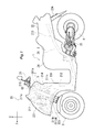
- FIG. 1 is a side view illustrating the outline of the overall configuration of the vehicle according to the first embodiment.
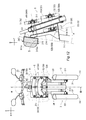
- FIG. 2 is a front view showing the configuration of the front portion of the vehicle when the vehicle is viewed from the front with the body cover removed.
- 3 is a cross-sectional view taken along line III-III in FIG.
- FIG. 4 is a view as seen from an arrow IX in FIG.
- FIG. 5 is a view corresponding to FIG. 2 showing a state in which the vehicle is tilted.
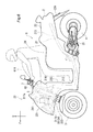
- FIG. 6 is a view corresponding to FIG. 1 showing a state in which the airbag is deployed.
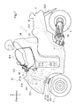
- FIG. 7 is a diagram illustrating an example of the upper limit position and the lower limit position of the airbag storage case in the vertical direction.
- FIG. 8 is a side view showing a schematic configuration of the vehicle according to the second embodiment with a vehicle body cover and the like removed.
- FIG. 9 is a front view illustrating the configuration of the front portion of the vehicle when the vehicle according to the second embodiment is viewed from the front with the vehicle body cover and the like removed.
- FIG. 10 is an enlarged side view of the front portion of the vehicle according to the second embodiment viewed from the side.
- FIG. 11 is an enlarged top view showing a connection structure between the first steering shaft and the second steering shaft.
- FIG. 12 is a configuration of the front portion of the vehicle when the vehicle is viewed from the front with the body cover removed, and a cross-sectional view taken along line III-III.
- the arrow F in the figure indicates the forward direction of the vehicle.
- An arrow U in the figure indicates the upward direction of the vehicle.
- An arrow R in the figure indicates the right direction of the vehicle.
- the front, rear, left, and right directions mean front, rear, left, and right directions as viewed from a rider who drives the vehicle.
- FIG. 1 is a side view illustrating the outline of the overall configuration of the vehicle 1 according to the first embodiment.
- the vehicle 1 includes a vehicle body 2, a pair of left and right front wheels 3, and a rear wheel 4. That is, the vehicle 1 in this embodiment is a tricycle having a pair of left and right front wheels 3.
- the vehicle body 2 includes a link mechanism 5, an airbag device 7, a vehicle body frame 21, a vehicle body cover 22, a handle 23, a seat 24, a power unit 25, a left shock absorber 33, and a right shock absorber 34. Prepare.
- the vehicle body frame 21 supports the power unit 25, the seat 24, and the like.
- the power unit 25 includes a power source such as an engine or an electric motor, and a speed change mechanism such as a transmission device.
- the body frame 21 is indicated by a broken line.
- the vehicle body frame 21 includes a head pipe 211 extending in the vertical direction, a front frame 212 extending from the head pipe 211 to the rear of the vehicle, and a rear frame 213 extending from the rear end of the front frame 212 to the rear of the vehicle.
- the head pipe 211 is disposed at the front portion of the vehicle 1.
- a link mechanism 5 is disposed around the head pipe 211.
- the head pipe 211 is supported by the front frame 212.
- a steering shaft 60 is rotatably inserted into the head pipe 211.
- the steering shaft 60 extends in the vertical direction.
- the 1st penetration part 211a protrudes ahead of the vehicle so that the link mechanism 5 may be penetrated.
- a second penetrating portion 211 b projects from the head pipe 211 to the front of the vehicle so as to penetrate the link mechanism 5.
- the third penetration part 211 c projects rearward of the vehicle so as to penetrate the link mechanism 5.
- a handle 23 extending in the left-right direction is attached to the upper end of the steering shaft 60.
- the front frame 212 extends rearward and downward from the front end connected to the head pipe 211.
- the rear frame 213 supports the seat 24 and a tail lamp (not shown).
- a support frame 214 extending in the vertical direction is connected to the upper portion of the front frame 212.
- the support frame 214 is disposed on the rear side of the head pipe 211 in the front-rear direction.
- the support frame 214 is also connected to the head pipe 211.
- an airbag storage case 215 (airbag storage portion) in which the airbag device 7 is stored.
- the configuration of the airbag storage case 215 will be described later.
- the vehicle body frame 21 is covered with a vehicle body cover 22 which is one of vehicle exterior parts.
- the vehicle body cover 22 includes a front cover 221, a pair of front fenders 223, a rear fender 224, and a leg shield 225.
- the front cover 221 is located in front of the seat 24 in the front-rear direction.
- the front cover 221 covers at least a part of the head pipe 211 and the link mechanism 5.
- Each front fender 223 is arranged above the pair of left and right front wheels 3 in the vertical direction. Each front fender 223 is disposed below the front cover 221 in the vertical direction. The rear fender 224 is disposed above the rear wheel 4 in the vertical direction.
- the leg shield 225 is disposed behind the head pipe 211 in the front-rear direction.
- the leg shield 225 extends in the vertical direction.
- the leg shield 225 is positioned on the front side with respect to the user's leg in a state where the user gets on the vehicle 1 in the front-rear direction.
- the pair of left and right front wheels 3 are positioned below the head pipe 211 and the link mechanism 5 in the vertical direction.
- the pair of left and right front wheels 3 are positioned below the front cover 221 in the vertical direction.
- FIG. 2 is a front view showing the vehicle 1 with the vehicle body cover 22 removed.
- the vehicle 1 includes the handle 23, the steering shaft 60, the head pipe 211, the pair of left and right front wheels 3, and the link mechanism 5.
- the pair of left and right front wheels 3 the left front wheel is referred to as a left front wheel 31, and the right front wheel is referred to as a right front wheel 32.
- the link mechanism 5 is connected to the left front wheel 31 and the right front wheel 32.
- the link mechanism 5 is rotatably attached to the head pipe 211.
- the link mechanism 5 includes a plurality of cross members 50 (see FIGS. 2 and 3) and a plurality of side members 55 (see FIG. 2).
- 3 is a cross-sectional view taken along line III-III in FIG. In FIG. 3, the rotating shaft such as the steering shaft 60 and the nut are not shown in cross section.
- the plurality of cross members 50 include an upper cross member 51 and a plurality of lower cross members 52.
- the upper cross member 51 includes a front upper cross member 51 ⁇ / b> A that is positioned on the front side of the head pipe 211 in the front-rear direction.
- the front upper cross member 51A is a flat member.
- the plurality of lower cross members 52 include a front lower cross member 52A located on the front side of the head pipe 211 and a rear lower cross member 52B located on the rear side of the head pipe 211 in the front-rear direction.
- Each of the front lower cross member 52A and the rear lower cross member 52B is a flat plate member.
- the plurality of cross members 50 are positioned on the front side of the head pipe 211 in the front-rear direction, on the rear side of the front cross member 50A including the front upper cross member 51A and the front lower cross member 52A, and on the rear side of the head pipe 211.
- the plurality of side members 55 includes a left side member 53 and a right side member 54 as shown in FIG.
- the front wheel 3 includes a left front wheel 31 and a right front wheel 32 that can be steered.
- the left front wheel 31 is disposed on the left side of the center of the vehicle 1 in the left-right direction.
- a first front fender 223a is disposed above the left front wheel 31 in the vertical direction.
- the right front wheel 32 is disposed on the right side of the center of the vehicle 1 in the left-right direction.
- a second front fender 223b is disposed above the right front wheel 32 in the vertical direction.
- the right front wheel 32 is disposed symmetrically with the left front wheel 31 with respect to the center of the vehicle 1 in the left-right direction.
- the left front wheel 31 is connected to the left shock absorber 33. Specifically, the left front wheel 31 is connected to the lower part of the left shock absorber 33.
- the left front wheel 31 is supported by the left shock absorber 33 so as to be rotatable about the axle 311.
- the axle 311 is disposed below the left shock absorber 33 so as to extend in the left-right direction of the body frame 21.
- the left front wheel 31 can rotate around the rotation shaft 312.
- the right front wheel 32 is connected to the right shock absorber 34. Specifically, the right front wheel 32 is connected to the lower part of the right shock absorber 34. The right front wheel 32 is supported by the right shock absorber 34 so as to be rotatable about the axle 321. The axle 321 is disposed below the right shock absorber 34 so as to extend in the left-right direction of the body frame 21. The right front wheel 32 can rotate around the rotation shaft 322.
- the vehicle 1 can change the traveling direction.
- the left shock absorber 33 absorbs an impact applied to the left front wheel 31. As shown in FIG. 2, the left shock absorber 33 is disposed below the link mechanism 5 in the vertical direction of the vehicle body frame 21. The left shock absorber 33 is provided between the left side member 53 and the left front wheel 31. The left shock absorber 33 is disposed so as to extend in the vertical direction of the vehicle body frame 21 along a left steering axis N ⁇ b> 1 that extends parallel to the steering shaft 60 and the head pipe 211. The left shock absorber 33 is disposed on the left side of the head pipe 211 in the left-right direction of the body frame 21. The left shock absorber 33 is disposed on the right side of the left front wheel 31 in the left-right direction of the body frame 21.
- the right shock absorber 34 absorbs an impact applied to the right front wheel 32.
- the right shock absorber 34 is disposed below the link mechanism 5 in the vertical direction of the body frame 21.
- the right shock absorber 34 is provided between the right side member 54 and the right front wheel 32.
- the right shock absorber 34 is disposed so as to extend in the vertical direction of the vehicle body frame 21 along a right steering axis N ⁇ b> 2 that extends parallel to the steering shaft 60 and the head pipe 211.
- the right shock absorber 34 is disposed on the right side of the head pipe 211 in the left-right direction of the body frame 21.
- the right shock absorber 34 is disposed on the left side of the right front wheel 32 in the left-right direction of the body frame 21.
- the left side member 53 is disposed on the left side of the head pipe 211 in the left-right direction of the body frame 21.
- the right side member 54 is disposed on the right side of the head pipe 211 in the left-right direction of the body frame 21.
- the left side member 53 and the right side member 54 are each a cylindrical member.
- the left side member 53 and the right side member 54 may be other columnar members or cylindrical members.
- the left side member 53 and the right side member 54 extend in the vertical direction of the vehicle body frame 21 in a state where the vehicle 1 is upright.
- a left bracket 335 to which the left shock absorber 33 is connected is provided below the left side member 53 in the vertical direction.
- the lower part of the left side member 53 supports the left shock absorber 33 so as to be rotatable around the left steering axis N1.
- a right bracket 336 to which the right shock absorber 34 is connected is provided below the right side member 54.
- the lower part of the right side member 54 supports the right shock absorber 34 so as to be rotatable around the right steering axis N2.
- the upper cross member 51 is a member extending in the left-right direction of the body frame 21 when viewed from the front of the vehicle 1.
- the upper cross member 51 is provided on the front side of the head pipe 211 in the front-rear direction.
- a first through hole 514 is provided at the center of the upper cross member 51 in the left-right direction in the left-right direction of the body frame 21.
- An upper left bearing 512 is provided at the left end of the upper cross member 51.
- An upper right bearing 513 is provided at the right end of the upper cross member 51.
- a first through portion 211 a extending from the head pipe 211 passes through the first through hole 514.
- the upper cross member 51 is provided with an upper intermediate bearing 511 between the first through portion 211 a and the first through hole 514. Therefore, the upper cross member 51 is rotatably supported with respect to the head pipe 211 by the first through portion 211 a and the upper intermediate bearing 511.
- the upper cross member 51 rotates relative to the head pipe 211 around the upper intermediate axis (intermediate axis) M1 that is the rotation center of the upper intermediate bearing 511. That is, the upper intermediate axis M ⁇ b> 1 is located inside the first through hole 514.
- the upper intermediate axis M1 is inclined with respect to the horizontal direction so as to be positioned higher toward the front of the vehicle.
- the upper cross member 51 is connected to the upper part of the left side member 53 via the upper left bearing 512 and is connected to the upper part of the right side member 54 via the upper right bearing 513. Yes. Thereby, the upper cross member 51 can rotate with respect to the left side member 53 and the right side member 54.
- 4 is a view as seen from the IX direction in FIG.
- the upper intermediate axis M1 that is the rotation center of the upper intermediate bearing 511
- the upper left axis (left axis) M2 that is the rotation center of the upper left bearing 512
- the upper right axis line (right axis line) M3 is parallel to each other.
- the plurality of lower cross members 52 are disposed below the upper cross member 51 in the vertical direction.
- the plurality of lower cross members 52 extend in the left-right direction when viewed from the front of the vehicle.
- the length in the left-right direction of the plurality of lower cross members 52 is substantially equal to the length in the left-right direction of the upper cross member 51.
- the plurality of lower cross members 52 include a front lower cross member 52 ⁇ / b> A located on the front side of the head pipe 211 and a rear lower cross member 52 ⁇ / b> B located on the rear side of the head pipe 211 in the front-rear direction. .
- a second through hole 524 is provided at the center in the left-right direction of the front lower cross member 52A.
- a lower left bearing 522 is provided on the left side of the second through hole 524 of the front lower cross member 52A.
- a lower right bearing 523 is provided to the right of the second through hole 524 of the front lower cross member 52A.
- the second through-hole 211b penetrates the second through-hole 524.
- a lower intermediate bearing 521 is provided between the second through portion 211b and the second through hole 524.
- the front lower cross member 52 ⁇ / b> A is rotatably supported with respect to the head pipe 211 by the second through portion 211 b and the lower intermediate bearing 521.
- the front lower cross member 52 ⁇ / b> A rotates relative to the head pipe 211 around the lower intermediate shaft M ⁇ b> 4 that is the rotation center of the lower intermediate bearing 521. That is, the lower intermediate shaft M4 is positioned inward of the second through hole 524.
- the rear lower cross member 52B has the same configuration as the front lower cross member 52A. That is, the third through hole 534 is provided in the center in the left-right direction of the rear lower cross member 52B.
- the third through-hole 211c passes through the third through-hole 534.
- a lower intermediate bearing 531 is provided between the third through portion 211 c and the third through hole 534.
- the rear lower cross member 52B is rotatably supported with respect to the head pipe 211 by the third through portion 211c and the lower intermediate bearing 531.
- the rear lower cross member 52 ⁇ / b> B rotates with respect to the head pipe 211 around the lower intermediate shaft M ⁇ b> 4 that is the rotation center of the lower intermediate bearing 531. That is, the lower intermediate shaft M4 is positioned inward of the third through hole 534.
- the rear lower cross member 52B is also provided with a lower left bearing and a lower right bearing similarly to the front lower cross member 52A.
- These lower left bearing and lower right bearing are the positions of the lower left bearing 522 and the lower right bearing 523 provided in the front lower cross member 52A when viewed from the axial direction of the lower intermediate shaft M4 in the rear lower cross member 52B. It is provided at the same position.
- the lower middle axis (intermediate axis) M4 that is the rotation center of the lower intermediate bearings 521 and 531
- the lower left axis (left axis) M5 that is the rotation center of the lower left bearing 522
- the lower right bearing The lower right axis (right axis) M6 that is the center of rotation of 523 is parallel to each other.
- the lower intermediate axis M4 is parallel to the upper intermediate axis M1.
- the position of the lower left bearing 522 in the left-right direction of the body frame 21 is the same as the position of the upper left bearing 512 in the left-right direction of the body frame 21 when the vehicle 1 is upright.
- the position of the lower right bearing 523 in the left-right direction of the body frame 21 is the same as the position of the upper right bearing 513 in the left-right direction of the body frame 21 when the vehicle 1 is upright.
- the lower cross member 52 is connected to the lower part of the left side member 53 via the lower left bearing 522.
- the lower cross member 52 is connected to the lower portion of the right side member 54 via the lower right bearing 523. Thereby, the lower cross member 52 can rotate with respect to the left side member 53 and the right side member 54.
- the movable region V1 in which the link mechanism 5 operates includes the movable regions of the upper cross member 51, the plurality of lower cross members 52, the left side member 53, and the right side member 54.
- the lower end of the movable region V1 is the lowermost position of the link mechanism 5 when the link mechanism 5 is operating, that is, the lower end of the movable region of the lower cross member 52 in this embodiment.
- the upper end of the movable region V1 is the uppermost position of the link mechanism 5 when the link mechanism 5 is operating, that is, the upper end of the movable region of the upper cross member 51 in this embodiment.
- the front-rear range of the movable region V1 is defined by the movable regions of the front upper cross member 51A and the front lower cross member 52A, while the rear side is movable of the rear lower cross member 52B. Defined by area. That is, the front surface (front surface) of the movable region V1 is defined by the front surfaces of the front upper cross member 51A and the front lower cross member 52A. The rear surface (back surface) of the movable region V1 is defined by the rear surface of the rear lower cross member 52B. Further, the range of the movable region V1 viewed from the front of the vehicle is M-shaped with a central portion on the lower side recessed as viewed from the front, as shown by a thick two-dot chain line in FIG.
- the link mechanism 5 is attached to the head pipe 211. For this reason, even when the steering shaft 60 rotates with the steering of the handle 23, the link mechanism 5 does not rotate with respect to the vehicle body frame 21.
- the tie rod 6 rotates together with the steering shaft 60 and transmits the rotation of the steering shaft 60 to the left front wheel 31 and the right front wheel 32. Thereby, the left front wheel 31 and the right front wheel 32 can be steered by the handle 23.
- the tie rod 6 is disposed in front of the head pipe 211 in the front-rear direction.
- the tie rod 6 extends in the left-right direction of the body frame 21.
- the tie rod 6 is disposed below the lower cross member 52 and above the left front wheel 31 and the right front wheel 32 in the vertical direction.
- the tie rod 6 is connected to the lower part of the steering shaft 60. Accordingly, when the steering shaft 60 is rotated, the tie rod 6 moves in the left-right direction.
- a left bracket 335 is provided below the left side member 53.
- the left bracket 335 is connected to the left shock absorber 33.
- the left bracket 335 is provided so as to be rotatable with respect to the left side member 53 around the left steering axis N1 extending in the extending direction of the left side member 53.
- the tie rod 6 is connected to the left bracket 335 so as to be rotatable about a rotation axis parallel to the left steering axis N1 with respect to the left side member 53.
- the rotation axis that relatively rotates the left bracket 335 and the left side member 53 is parallel to the rotation axis that relatively rotates the left bracket 335 and the tie rod 6.
- a right bracket 336 is provided below the right side member 54.
- the right bracket 336 is connected to the right shock absorber 34.
- the right bracket 336 is provided to be rotatable with respect to the right side member 54 around the right steering axis N2 extending in the direction in which the right side member 54 extends. Further, the tie rod 6 is connected to the right bracket 336 so as to be rotatable around a rotation axis parallel to the right steering axis N2 with respect to the right side member 54. That is, the rotation axis on which the right bracket 336 and the right side member 54 rotate relative to each other and the rotation axis on which the right bracket 336 and the tie rod 6 rotate relatively are parallel to each other.
- the tie rod 6 moves in the left-right direction. Then, as the tie rod 6 moves, the left bracket 335 rotates around the left steering axis N1 with respect to the left side member 53. As the tie rod 6 moves, the right bracket 336 rotates around the right steering axis N2 with respect to the right side member 54.
- the left bracket 335 transmits the steering of the handle 23 to the left front wheel 31, and the right bracket 336 also transmits the steering of the handle 23 to the right front wheel 32.
- the vehicle body 2 of the vehicle 1 includes the airbag device 7.
- the airbag device 7 is located behind the link mechanism 5 in the front-rear direction.
- the airbag device 7 is positioned below the upper end of the handle 23 and above the lower end of the movable region V1 of the link mechanism 5 in the vertical direction.
- the airbag device 7 is deployed from the front with respect to the rider seated on the seat 24 when a collision of the vehicle 1 is detected by a sensor (not shown) or the like.
- an airbag storage case 215 is connected to the support frame 214 connected to the upper part of the front frame 212.
- the airbag storage case 215 has a rectangular bottom surface 216 and four side surfaces 217 extending from the outer periphery of the bottom surface 216 in the thickness direction of the bottom surface. That is, the airbag storage case 215 is formed in a box shape having an opening 215a.
- a storage space S in which the airbag device 7 is stored is formed by the bottom surface 216 and the four side surfaces 217.
- FIG. 12 An example of the arrangement of the airbag storage case 215 is shown in FIG. FIG. 12 is the same view as FIG. 2 and FIG. At least a part of the airbag storage case 215 has an upper end at the uppermost position among the first through part 211a, the second through part 211b, and the third through part 211c that supports the link mechanism 5 on the head pipe 211 in the vertical direction. It is located below the upper end of the penetrating part located.
- the airbag device 7 In the storage space S of the airbag storage case 215, the airbag device 7 is stored.
- the airbag device 7 includes an airbag 611 (see FIG. 6) and an inflator (not shown) that supplies inflation gas to the airbag 611.
- the airbag 611 is stored in the storage space S in a folded state.
- the airbag 611 When the inflator is activated, the airbag 611 is expanded outward from the opening 215a of the airbag storage case 215 while being inflated by the inflation gas supplied from the inflator (see FIG. 6). That is, the airbag 611 is deployed from the opening 215a of the airbag storage case 215.
- the surface surrounded by the opening end in the opening 215 a of the airbag storage case 215 is parallel to the bottom surface 216, and therefore the surface surrounded by the opening end is the airbag 611. This corresponds to the development surface 611a.
- the deployment surface 611a is a plane orthogonal to the deployment direction of the airbag 611.
- the airbag storage case 215 is disposed so that the normal direction of the deployment surface 611a of the airbag 611 extends rearward and upward of the vehicle. As shown in FIGS. 1 and 4, the airbag storage case 215 is arranged so that the opening 215 a of the airbag 611 is positioned in front of the rear end of the handle 23 in the front-rear direction.
- the airbag storage case 215 is arranged so that the opening 215a is positioned below the handle 23 in the vertical direction. Further, as shown in FIG. 2, the airbag storage case 215 is disposed on the right side of the left ends of the plurality of cross members 50 of the link mechanism 5 and on the left side of the right ends of the plurality of cross members 50 in the left-right direction. Yes. Furthermore, the airbag storage case 215 is disposed so as to overlap with the center portion in the left-right direction of the plurality of cross members 50 as viewed from the front of the vehicle. In the present embodiment, the airbag storage case 215 is arranged so that the center in the left-right direction overlaps the center portion in the left-right direction of the plurality of cross members 50 when viewed from the front of the vehicle.
- FIG. 5 is a front view when the vehicle 1 is tilted at an angle T in the left-right direction with respect to the vertical direction from the state of FIG. The vehicle 1 is inclined with respect to the vertical direction when the link mechanism 5 is operated.
- the right side RF of the body frame 21 means the right side in a direction orthogonal to the axial direction of the head pipe 211 when the vehicle 1 is viewed from the front.
- the upper UF of the vehicle body frame 21 means the upper side of the head pipe 211 in the axial direction when the vehicle 1 is tilted when the vehicle 1 is viewed from the front.
- the upper side of the body frame 21 coincides with the upper side of the head pipe 211 in the axial direction when the vehicle 1 is viewed from the front. Further, when the vehicle 1 is in an upright state, the right side RF of the body frame 21 coincides with the right side R in the horizontal direction.
- the upper cross member 51 and the lower cross member 52 are translated in the left-right direction with the extending direction thereof being parallel to the road surface G.
- the upper cross member 51 and the lower cross member 52 rotate with respect to the left side member 53 about the upper left axis M2 and the lower left axis M5 of the lower left bearing 522 as the rotation centers, respectively.
- the upper cross member 51 and the lower cross member 52 also rotate relative to the right side member 54 with the upper right axis M3 of the upper right bearing 513 and the lower right axis M6 of the lower right bearing 523 as rotation centers, respectively.
- the upper cross member 51, the lower cross member 52, the left side member 53, and the right side member 54 form a rectangle when the vehicle 1 is upright when the vehicle 1 is viewed from the front in the direction of the upper intermediate axis M ⁇ b> 1.
- the vehicle 1 is deformed to form a parallelogram by the inclination of the vehicle 1.
- the link mechanism 5 operates so that the left end of the upper cross member 51 moves to the left in the left-right direction of the vehicle body frame 21 rather than the left end of the lower cross member 52.
- the left shock absorber 33 and the right shock absorber 34 are inclined with respect to the vertical direction. In this way, when the vehicle 1 tilts to the left with respect to the vertical direction, the vehicle 1 changes from the upright state shown in FIG. 2 to the inclined state shown in FIG.
- the vehicle 1 can be turned by tilting the vehicle 1 left and right while traveling. As described above, the direction of the left front wheel 31 and the right front wheel 32 can be changed by operating the handle 23.
- the movable region V1 of the cross member 50 includes a front movable region V1A that is a movable region of the front cross member 50A relative to the vehicle body frame 21, and a rear movable region that is a movable region of the rear cross member 50B relative to the vehicle body frame 21. V1B.
- the airbag storage case 215 is supported by the support frame 214 so that the opening 215a is opened rearward and upward.
- the bottom surface 216 of the airbag storage case 215 is disposed along the back surface of the movable region V1 (V1B).
- the bottom surface 216 along the back surface of the movable region V1 (V1B) includes not only the case where the bottom surface 216 and the back surface are parallel, but also the case where the angle ⁇ formed between the bottom surface 216 and the back surface is 45 degrees or less. .
- the rear surface is a surface including the rear portion of the movable region V1 of the link mechanism 5. That is, it is a surface including a locus drawn by the rear lower cross member 52B when the rear lower cross member 52B of the link mechanism 5 moves relative to the vehicle body frame 21.
- the rear lower cross member 52B has a flat plate shape. Therefore, the back surface includes a rear surface of the rear lower cross member 52B.
- At least a part of the airbag storage case 215 is located below the upper end of the movable region V1 of the link mechanism 5. Specifically, as shown in FIG. 3, a part of the airbag storage case 215 is positioned below the upper end of the front movable region V1A of the front cross member 50A of the link mechanism 5 in the vertical direction.
- the bottom surface 216 of the airbag storage case 215 is along the surface (rear surface) including the vehicle rear side portion of the movable region V1 of the link mechanism 5.
- the airbag storage case 215 can be arranged at a position closer to the link mechanism 5. Accordingly, the airbag storage case 215 can be prevented from protruding toward the rider, and the front portion of the vehicle 1 can be prevented from becoming large.
- the airbag storage case 215 has the top end of the first through portion 211a, the second through portion 211b, and the third through portion 211c that support the link mechanism 5 on the head pipe 211 in the vertical direction. It is located below the upper end of the penetrating portion located on the upper side (the upper end of the link support portion). Therefore, the airbag storage case 215 can be disposed closer to the rider in the vertical direction. Thereby, the airbag 611 can be deployed at a position closer to the rider.
- the airbag storage case 215 is positioned below the upper end of the movable region V1 of the link mechanism 5 in the vertical direction. Therefore, the airbag storage case 215 can be disposed closer to the rider in the vertical direction. Thereby, the airbag 611 can be deployed at a position closer to the rider in the vertical direction.
- the airbag storage case 215 has an opening 215a disposed below the handle 23 in the vertical direction. Therefore, the airbag storage case 215 can be disposed in the front portion of the vehicle. Thereby, the airbag 611 can be deployed from the front with respect to the rider.
- the airbag storage case 215 is disposed on the right side of the left ends of the plurality of cross members 50 of the link mechanism 5 and on the left side of the right ends of the plurality of cross members 50 in the left-right direction. Thereby, in the vehicle 1, the airbag storage case 215 can be arrange
- the airbag storage case 215 is disposed so as to overlap with the central portion in the left-right direction of the plurality of cross members 50 as viewed from the front of the vehicle. Thereby, in the vehicle 1, the airbag storage case 215 can be arrange
- the airbag storage case 215 is disposed at a position below the handle 23 in the vertical direction and at least partially overlapping the front upper cross member 51A when viewed from the front of the vehicle. It is preferable. Accordingly, when the airbag 611 is deployed, the thigh of the rider seated on the seat 24 can be deployed so as to be restrained from above by the airbag 611.
- the lower limit position of the airbag storage case 215 in the case where the airbag 611 is deployed so as to suppress the thigh of the rider seated on the seat 24 from above is shown by a one-dot chain line. Is indicated by a two-dot chain line. In FIG.
- an airbag 611 indicated by a one-dot chain line indicates a state in which the airbag 611 is deployed when the airbag storage case 215 is positioned at the one-dot chain line position (lower limit position).
- the illustrated airbag 611 shows a state where the airbag 611 is deployed when the airbag storage case 215 is located at the position of the two-dot chain line (upper limit position).
- the link mechanism 5 includes a front upper cross member 51A, a front lower cross member 52A, and a rear lower cross member 52B.
- no cross member is provided on the rear side of the front upper cross member 51A in the front-rear direction. Therefore, the airbag storage case 215 can be compactly disposed with respect to the link mechanism 5 by disposing the airbag storage case 215 in the space behind the front upper cross member 51 ⁇ / b> A in the front-rear direction. Thereby, the front part of the vehicle 1 can be made compact.
- the airbag storage case 215 is disposed behind the link mechanism 5.
- the link mechanism 5 includes a plurality of cross members 50 and a plurality of side members 55, and has relatively high rigidity in the body frame 21. Therefore, even when the front portion of the vehicle 1 collides, the airbag storage case 215 is not easily damaged by the link mechanism 5.
- the vehicle 1000 according to the second embodiment is different from the vehicle 1 according to the first embodiment in that it includes a first steering shaft 1060A and a second steering shaft 1060B.
- the same reference numerals as those in the first embodiment are assigned to the same parts as those in the first embodiment, and the description thereof will be omitted.
- FIG. 8 is a side view of the entire vehicle 1000 viewed from the left side with the vehicle body cover removed.
- the vehicle 1000 includes a vehicle main body 1002, a pair of left and right front wheels 3, a rear wheel 4, a link mechanism 1005, an airbag device 7, and a connecting member 1007.
- the vehicle 1000 according to the second embodiment is also a tricycle having a pair of left and right front wheels 3.
- the vehicle main body 1002 includes a vehicle body frame 1021, a vehicle body cover (not shown), a seat 24, and a power unit 25.
- the body frame 1021 extends in the front-rear direction of the vehicle 1000.
- the vehicle body frame 1021 includes a head pipe 1211 extending in the vertical direction, a support member 1231 disposed in front of the head pipe 1211, a front frame 1212 extending rearward from the support member 1231, and a vehicle from the rear end of the front frame 1212. And a rear frame 1213 extending rearward.
- the head pipe 1211 extends in the vertical direction.
- the head pipe 1211 rotatably supports the first steering shaft 1060A (steering shaft) inserted therein.
- a support frame 1214 extending toward the rear of the vehicle is provided on the rear side of the head pipe 1211.
- An airbag storage case 215 in which the airbag device 7 is stored is attached to the distal end portion of the support frame 1214.
- the airbag device 7 is covered by the vehicle body cover on the rear side in the front-rear direction as in the configuration of the first embodiment.
- the support member 1231 is disposed on the front side of the head pipe 1211 in the front-rear direction.
- the support member 1231 is a cylindrical member.
- the support member 1231 rotatably supports the second steering shaft 1060B inserted therein and supports the link mechanism 1005 on the outer peripheral surface.
- the head pipe 1211 and the support member 1231 are connected.
- a handle 23 extending in the vehicle width direction is attached to the upper end of the first steering shaft 1060A.
- the front frame 1212 has an upper front frame 1212A and a lower front frame 1212B.
- the upper front frame 1212A and the lower front frame 1212B extend in the front-rear direction.
- the front side of the upper front frame 1212A is connected to the support member 1231 in the front-rear direction.
- the lower front frame 1212B is disposed below the upper front frame 1212A in the vertical direction.
- the front side in the front-rear direction of the lower front frame 1212B is connected to the lower end portion of the support member 1231.
- the rear frame 1213 supports the seat 24 and the tail lamp (not shown).
- FIG. 9 is a front view of the front portion of the vehicle 1000 as viewed from the front with the body cover removed. As shown in FIG. 9, the vehicle 1000 of the present embodiment also includes a left front wheel 31 and a right front wheel 32, as in the vehicle 1 of the first embodiment.
- the link mechanism 1005 is connected to the left front wheel 31 via the left shock absorber 33 and is connected to the right front wheel 32 via the right shock absorber 34.
- the link mechanism 1005 is rotatably attached to the support member 1231.
- the link mechanism 1005 includes a plurality of cross members 1050 and a plurality of side members 1055.
- the plurality of cross members 1050 include an upper cross member 1051 and a plurality of lower cross members 1052, as shown in FIGS.
- the upper cross member 1051 includes a front upper cross member 1051 ⁇ / b> A that is positioned on the front side of the support member 1231 in the front-rear direction.
- the front upper cross member 1051A is a flat member.
- the plurality of lower cross members 1052 include a front lower cross member 1052A located on the front side of the support member 1231 and a rear lower cross member 1052B located on the rear side of the support member 1231 in the front-rear direction.
- Each of the front lower cross member 1052A and the rear lower cross member 1052B is a flat plate member.
- the plurality of side members 1055 include a left side member 1053 and a right side member 1054, as shown in FIG.
- the upper cross member 1051 and the plurality of lower cross members 1052 are rotatably supported by the support member 1231 at the center in the left-right direction.
- the link mechanism 1005 has the same configuration as that of the link mechanism 5 of Embodiment 1 except that the upper cross member 1051 and the plurality of lower cross members 1052 are rotatably supported by the support member 1231. Therefore, the link mechanism 1005 operates in the same manner as the link mechanism 5 of the first embodiment. In the present embodiment, the detailed configuration and operation of the link mechanism 1005 will not be described.
- reference numeral 1006 denotes a tie rod having the same function as the tie rod 6 of the first embodiment.
- the tie rod 1006 is connected to the lower part of the second steering shaft 1060B. Similar to the configuration of the first embodiment, the tie rod 1006 is connected to the left shock absorber 33 that rotatably supports the left front wheel 31 via the left bracket 1335. Similar to the configuration of the first embodiment, the tie rod 1006 is connected via the right bracket 1336 to the right shock absorber 34 that rotatably supports the right front wheel 32. Accordingly, when the second steering shaft 1060B is rotated, the tie rod 1006 moves in the left-right direction.
- the second steering shaft 1060B is rotatably supported by a support member 1231.
- the second steering shaft 1060B is connected to the first steering shaft 1060A rotatably supported by the head pipe via a connecting member 1007.
- FIG. 10 is an enlarged side view of the front portion of the vehicle 1000 viewed from the side.
- FIG. 11 is an enlarged top view showing a connection structure between the first steering shaft 1060A and the second steering shaft 1060B.
- the connecting member 1007 includes a first fixing portion 1071 connected to the first steering shaft 1060A, a second fixing portion 1072 connected to the second steering shaft 1060B, and a first fixing portion.
- a connecting shaft 1073 that connects the portion 1071 and the second fixing portion 1072;
- the first fixing portion 1071 is disposed below the handle 23 in the vertical direction.
- the first fixed portion 1071 is connected to the upper portion of the first steering shaft 1060A.
- the first fixed portion 1071 extends from the first steering shaft 1060A to the left of the vehicle.
- the second fixed portion 1072 is connected to the upper end of the second steering shaft 1060B.
- the second fixed portion 1072 extends from the second steering shaft 1060B to the left side of the vehicle.
- the connecting shaft 1073 is disposed below the handle 23 in the vertical direction. One end of the connecting shaft 1073 is connected to the left end of the first fixed portion 1071 so as to be rotatable about an axis extending in the vertical direction. The other end of the connecting shaft 1073 is connected to the left end of the second fixed portion 1072 so as to be rotatable about an axis extending in the vertical direction.
- the first fixing portion 1071 also rotates clockwise together with the first steering shaft 1060A.
- the connecting shaft 1073 is displaced forward of the vehicle. Due to the displacement of the connecting shaft 1073, the second fixed portion 1072 and the second steering shaft 1060B are rotated clockwise.
- the first fixing portion 1071 also rotates counterclockwise together with the first steering shaft 1060A.
- the connecting shaft 1073 is displaced rearward of the vehicle. Due to the displacement of the connecting shaft 1073, the second fixing portion 1072 and the second steering shaft 1060B are rotated counterclockwise.
- the rotation of the first steering shaft 1060A can be transmitted to the second steering shaft 1060B.
- the tie rod 1006 is rotated by the rotation of the second steering shaft 1060B. Accordingly, the left front wheel 31 connected to the tie rod 1006 via the left bracket 1335 and the left shock absorber 33 and the right front wheel 32 connected to the tie rod 1006 via the right bracket 1336 and the left shock absorber 34 are rotated. be able to.
- the link mechanism 1005 operates in the same manner as the link mechanism 5 by tilting the vehicle body 1000 with respect to the vertical direction. That is, the upper cross member 1051 and the lower cross member 1052 translate in the left-right direction in a state where the extending direction is parallel to the road surface. The upper cross member 1051 and the lower cross member 1052 rotate with respect to the left side member 1053, respectively. Further, the upper cross member 1051 and the lower cross member 1052 rotate with respect to the right side member 1054, respectively.
- the link mechanism 1005 allows the upper cross member 1051, the lower cross member 1052, the left side member 1053, and the right side member 1054 to form a rectangle in the upright state of the vehicle 1000 while the vehicle 1000 is viewed from the front. It is deformed so as to constitute a parallelogram with an inclination of 1000.
- the movable region V2 of the link mechanism 1005 has a plurality of cross members 1050 and a plurality of cross sections as in the link mechanism 1005 of the first embodiment. This is a region including the movable region of the side member 1055.
- the movable region V2 of the link mechanism 1005 is shown in FIGS.
- the lower end of the movable region V2 is the lowest position of the link mechanism 1005 when the link mechanism 1005 is operating, that is, the lower end of the movable region of the lower cross member 1052 in this embodiment.
- the upper end of the movable region V2 is the uppermost position of the link mechanism 1005 when the link mechanism 1005 is operating, that is, the upper end of the movable region of the upper cross member 1051 in this embodiment.
- the range in the front-rear direction in the movable region V2 is defined by the movable region of the front upper cross member 1051A and the front lower cross member 1052A, while the rear side is defined by the movable region of the rear lower cross member 1052B. That is, the front side of the movable region is defined by the front surfaces of the front upper cross member 1051A and the front lower cross member 1052A. The rear side of the movable region is defined by the rear surface of the rear lower cross member 1052B. Further, the range of the movable region viewed from the front of the vehicle is M-shaped with the central portion on the lower side recessed as viewed from the front, as shown by a thick dashed line in FIG.
- the movable region V2 of the link mechanism 1005 includes a movable region V2A of the upper cross member 1051 and the front lower cross member 1052A, and a movable region V2B of the rear lower cross member 1052B.
- the airbag device 7 Similarly to the vehicle 1 according to the first embodiment, the airbag device 7 according to the present embodiment is located on the rear side of the link mechanism 1005 in the front-rear direction. Further, the airbag device 7 is located below the upper end of the handle 23 and above the lower end of the movable region V2 of the link mechanism 1005 in the vertical direction (see FIG. 8). The airbag device 7 is deployed from the front with respect to the rider seated on the seat 24 when a collision of the vehicle 1000 is detected by a sensor (not shown) or the like.
- An airbag storage case 215 is connected to the support frame 1214 connected to the head pipe 1214.
- the airbag storage case 215 is formed in a box shape having an opening 215a.
- a surface surrounded by the opening end of the opening 215a corresponds to the deployment surface 611a of the airbag 611.
- the deployment surface 611a is a plane orthogonal to the deployment direction of the airbag 611. Since the configuration of the airbag storage case 215 is the same as that in the first embodiment, a detailed description of the configuration of the airbag storage case 215 is omitted.
- the airbag storage case 215 is located above the link mechanism 1005 in the vertical direction. As shown in FIGS. 8 and 10, the airbag storage case 215 is arranged so that the opening 215 a of the airbag storage case 215 is located on the vehicle front side with respect to the rear end of the handle 23 in the front-rear direction. The airbag storage case 215 is arranged so that the opening 215a of the airbag storage case 215 is positioned below the handle 23 in the vertical direction.
- the airbag storage case 215 is disposed on the right side of the left ends of the plurality of cross members 1050 of the link mechanism 1005 and on the left side of the right ends of the plurality of cross members 1050 in the left-right direction. Furthermore, the airbag storage case 215 is disposed so as to overlap with the central portion in the left-right direction of the plurality of cross members 1050 when viewed from the front of the vehicle. In the present embodiment, the airbag storage case 215 is disposed so that the center in the left-right direction overlaps the center portion in the left-right direction of the plurality of cross members 1050 when viewed from the front of the vehicle.
- the airbag storage case 215 is supported by the support frame 1214 so that the opening 215a is opened rearward and upward.
- the bottom surface 216 of the airbag storage case 215 is disposed along the back surface of the movable region V2 (V2B).
- the bottom surface 216 along the back surface of the movable region V2 (V2B) includes not only the case where the bottom surface 216 and the back surface are parallel, but also the case where the angle ⁇ between the bottom surface 216 and the back surface is 45 degrees or less. .
- the rear surface is a surface including the rear portion of the movable region V2 of the link mechanism 1005 in the front-rear direction. That is, it is a surface including a locus drawn by the rear lower cross member 1052B when the rear lower cross member 1052B of the link mechanism 1005 moves relative to the vehicle body frame 1021.
- the rear lower cross member 1052B has a flat plate shape. Therefore, the rear surface includes a rear surface of the rear lower cross member 1052B in the front-rear direction.
- the airbag storage case 215 is positioned above the movable region V2 of the link mechanism 1055 in the vertical direction.
- the airbag storage case 215 can be disposed at a position closer to the link mechanism 1005 by disposing the airbag storage case 215 so that the bottom surface 216 is along the back surface of the movable region V2 (V2B). .
- V2B the movable region
- the airbag storage case 215 is arranged so that the opening 215a is positioned below the handle 23 in the vertical direction. Therefore, the airbag storage case 215 can be disposed in the front portion of the vehicle. As a result, the airbag 611 can be deployed from the front of the vehicle with respect to the rider.
- the airbag storage case 215 is disposed on the right side of the left ends of the plurality of cross members 1050 of the link mechanism 1005 and on the left side of the right ends of the plurality of cross members 1050 when viewed from the front of the vehicle. Thereby, in the vehicle 1000, the airbag storage case 215 can be arrange
- the airbag storage case 215 is arranged so as to overlap with the central portion in the left-right direction of the plurality of cross members 1050 when viewed from the front of the vehicle. Thereby, in the vehicle 1000, the airbag storage case 215 can be disposed closer to the center in the left-right direction. Therefore, the airbag 611 can be more reliably deployed between the rider and the vehicle main body 1002.
- the airbag storage case 215 is arranged so that at least a part thereof is positioned below the upper end of the movable region V1 of the link mechanism 5 in the vertical direction.
- the airbag storage case 215 may be disposed so as to be positioned above the movable region V2 of the link mechanism 1005 in the vertical direction, for example, as shown in FIG.
- the airbag storage case 215 includes at least a part of the first through portion 211a, the second through portion 211b, and the third through portion 211c that support the link mechanism 5 on the head pipe 211 in the vertical direction.
- the upper end of the penetrating portion located on the uppermost side is disposed below the upper end of the penetrating portion.
- the airbag storage case 215 is arranged above the upper end of the penetrating portion whose upper end is located on the uppermost side among the first penetrating portion 211a, the second penetrating portion 211b, and the third penetrating portion 211c in the vertical direction. May be.
- the airbag storage case 215 is arranged so that the opening 215a is positioned below the handle 23. However, if the airbag storage case 215 is positioned below the upper end of the handle 23, and at least a part of the airbag storage case 215 is positioned above the lower end of the movable region V1 of the link mechanism 5.
- the position of the opening 215a is not particularly limited.
- the airbag storage case 215 is on the right side of the left ends of the cross members 50 and 1050 of the link mechanisms 5 and 1005 and on the left side of the right ends of the cross members 50 and 1050 in the left-right direction. Has been placed. However, the airbag storage case 215 may be disposed on the left side of the left ends of the plurality of cross members 50 and 1050 of the link mechanism 5 or on the right side of the right ends of the plurality of cross members 50 and 1050 in the left-right direction.
- the airbag storage case 215 is disposed so as to overlap with the central portion in the left-right direction of the plurality of cross members 50, 1050 when viewed from the front of the vehicle.
- the airbag storage case 215 may be disposed so as not to overlap the central portion of the plurality of cross members 50, 1050 in the left-right direction when viewed from the front of the vehicle.
- the airbag storage case 215 is arranged so that the normal line of the deployment surface 611a of the airbag 611 extends rearward and upward of the vehicle.
- the airbag storage case 215 may be arranged so that the normal line of the deployment surface 611a extends in a direction other than the rear and upper direction as long as the airbag 611 can be deployed with respect to the rider.
- the front upper cross members 51A and 1051A are flat members, and the front lower cross members 52A and 1052A and the rear lower cross members 52B and 1052B are flat members.
- the front upper cross members 51A and 1051A, the front lower cross members 52A and 1052A, and the rear lower cross members 52B and 1052B may be members having a shape other than a flat plate shape.
- the link mechanisms 5 and 1005 include front upper cross members 51A and 1051A, front lower cross members 52A and 1052A, and rear lower cross members 52B and 1052B. That is, in the link mechanisms 5 and 1005, no cross member is provided on the rear side of the front upper cross members 51A and 1051A in the front-rear direction. However, a rear upper cross member may be provided on the rear side of the front upper cross members 51A and 1051A.
Landscapes
- Engineering & Computer Science (AREA)
- Mechanical Engineering (AREA)
- Automatic Cycles, And Cycles In General (AREA)
- Vehicle Body Suspensions (AREA)
Abstract
リンク機構及びエアバッグを有する車両において、車両前部の大型化を抑制可能な構成を得る。車両は、車両前方から見て左右に配置された左前輪及び右前輪と、左緩衝装置と、右緩衝装置と、右サイド部材、左サイド部材及び複数のクロス部材50を含むリンク機構5と、底面216及び側面217を有し、底面216及び側面217によって形成された収納空間S内にエアバッグが展開前の状態で収納されたエアバッグ収納ケース215とを備える。エアバッグ収納ケース215は、前後方向においてリンク機構5よりも後側に位置するとともに、上下方向においてハンドル23の上端よりも下側で、且つ、エアバッグ収納部215の少なくとも一部がリンク機構5における右サイド部材54、左サイド部材53及びクロス部材50の可動領域V1の下端よりも上側に位置し、車両側方から見て、底面216が、可動領域V1における後側部分を含む面に沿うように配置されている。
Description
本発明は、リンク機構及びエアバッグを備えた車両に関する。
従来より、車体フレームと、前部に配置されたリンク機構と、2つの前輪とを有し、前記車体フレームが車幅方向に傾斜する車両が知られている。例えば非特許文献1には、このような車両として、前記2つの前輪がリンク機構に接続されているとともに、該リンク機構が、車体フレームの一部を構成し且つ車両の前部に設けられたリンク支持部によって支持された構成が開示されている。
前記非特許文献1には、前記リンク機構が、車両の前後方向において、前記リンク支持部の前側及び後側に前後方向に対向して配置された2対のクロス部材を有する点が開示されている。これにより、車両にライダーが乗車した状態で、前記リンク機構の一部が、前記ライダーと前記リンク支持部との間に位置する。
上述のようなリンク機構を有する車両では、該リンク機構とライダーとの干渉を避けるために、前記リンク機構を有しない車両に設けられたヘッドパイプ等に比べて、前記リンク支持部は前側に位置する。
また、特許文献1には、上述のようなリンク機構を有する車両において、該リンク機構の上方にエアバッグが配置されている構成が開示されている。具体的には、前記特許文献1に開示されている構成では、リンク支持部の前側に配置されたクロス部材の上側にエアバッグが配置されている。すなわち、前記特許文献1に開示されている構成では、前記エアバッグは、前記リンク機構を避けるように、ハンドルの前側に配置されている。
Catalogo parti di ricambio, MP3 300 ie LT Mod. ZAPM64102, Piaggio社
ところで、特許文献1及び非特許文献1に開示されているようなリンク機構は、右前輪及び左前輪を車体フレームに対して上下方向に変位可能に支持している。
具体的には、リンク機構は、車体フレームの上下方向に延びた左サイド部材及び右サイド部材と、前記左サイド部材を左端部で支持するとともに前記右サイド部材を右端部で支持し、中間部が前記車体フレームのリンク支持部に回転可能に支持された複数のクロス部材と、を含んでいる。
前記クロス部材は、左端部で前記左サイド部材を前記車体フレームの前後方向に延びる左軸線の回りに回転可能に支持するとともに、右端部で前記右サイド部材を前記左軸線に平行な右軸線の回りに回転可能に支持する。
そのため、車体フレームが鉛直に対して左右方向に傾斜する際に、リンク機構を構成する部材は大きく動く。すなわち、上述のような車両の構成の場合、リンク機構の各部材が動く範囲である、リンク機構の可動領域は、比較的大きい。
ところで、車両の衝突時等においてライダーに対してエアバッグを展開する場合、該ライダーよりも前側の位置で且つ該ライダーにより近い位置からエアバッグを展開することが好ましい。そのため、車両前部に位置するリンク機構の周囲にエアバッグを配置することが好ましい。
しかしながら、上述の可動領域を有するリンク機構と干渉しないように、該リンク機構の周囲にエアバッグを配置した場合、エアバッグの配置によっては車両前部が大型化する可能性がある。
したがって、本発明は、リンク機構及びエアバッグを有する車両において、車両前部の大型化を抑制可能な構成を得ることを目的とする。
車両にエアバッグを設けた場合、該エアバッグはライダーと車体との間に展開される。そのため、エアバッグが展開前の状態で収納されたエアバッグ収納部を、エアバッグが展開される開口ができるだけライダーの前側に位置付けられるように、車体に取り付けることが好ましい。
ところで、リンク機構を有する車両の場合には、車両前部で該リンク機構を支持するリンク支持部と、ライダーとの間に、リンク機構の一部が位置付けられる。このリンク機構は、構成部材の可動領域が比較的大きいため、車体が左右方向に傾斜する際に大きく動く。そのため、リンク機構の可動領域を避けて、上述の好ましい位置にエアバッグ収納部を配置しようとすると、車両前部が大型化する可能性がある。
これに対し、リンク機構を有しない車両の場合には、車両前部に配置される部品は固定部品が多いため、上述のリンク機構を有する車両のように可動部品の可動領域を確保する必要がない。よって、リンク機構を有しない車両の場合には、リンク機構を有する車両のように、車両前部が大型化する可能性はない。すなわち、リンク機構を有しない車両の場合には、そもそも、エアバッグを可動部品の近くに配置することを検討する必要がない。
発明者らは、リンク機構を有する車両において、エアバッグの機能及びレイアウトを検討する中で、リンク機構の構成部材が動いた際に描く軌跡によって、リンク機構の可動領域の後側に、所定の形状の面(以下、可動領域の背面という)が形成されることに気づいた。また、発明者らは、前記リンク機構の可動領域の背面は、車両の上下方向に延びている点にも気づいた。
一方、前記リンク機構を支持するリンク支持部は、車両にライダーが乗車した状態で該ライダーとリンク機構との干渉を避けるために、リンク機構を有しない車両に設けられているヘッドパイプ等に比べて、前側に設けられている。そのため、前記リンク機構を有する車両では、ライダーの前方で且つ該ライダーと車体との間に、比較的、広いスペースを有する。
発明者らは、上述のスペースを有効利用しつつ、車両前部の大型化を抑制可能な構成を鋭意検討した。その結果、発明者らは、以上の点を総合的に鑑みて、以下のような構成に想到した。
本発明の一実施形態に係る車両は、エアバッグを備えた車両である。この車両は、ステアリングシャフトに接続されたハンドルと、前記ステアリングシャフトを回転可能に支持する車体フレームと、車両の前方から見て左右に配置され、操舵可能な左前輪及び右前輪と、下部によって前記左前輪を支持し、前記車体フレームの上下方向において、前記左前輪に加わる衝撃を緩衝する左緩衝装置と、下部によって前記右前輪を支持し、前記車体フレームの上下方向において、前記右前輪に加わる衝撃を緩衝する右緩衝装置と、前記右緩衝装置の上部を前記車体フレームの上下方向に延びる右操舵軸線回りに回転可能に支持する右サイド部材と、前記左緩衝装置の上部を前記右操舵軸線と平行な左操舵軸線回りに回転可能に支持する左サイド部材と、前記右サイド部材を右端部で前記車体フレームの前後方向に延びる右軸線回りに回転可能に支持し、前記左サイド部材を左端部で前記右軸線に平行な左軸線回りに回転可能に支持し、中間部が前記車体フレームに前記右軸線及び前記左軸線に平行な中間軸線回りに回転可能に支持される複数のクロス部材と、を含むリンク機構と、底面及び側面を有するとともに、前記底面及び前記側面によって形成され且つ前記側面によって囲まれた開口を有する収納空間内に前記エアバッグが展開前の状態で収納されたエアバッグ収納部とを備える。前記エアバッグ収納部は、前後方向において前記リンク機構よりも後側に位置するとともに、上下方向において前記ハンドルの上端よりも下側で、且つ、前記エアバッグ収納部の少なくとも一部が前記リンク機構における前記右サイド部材、前記左サイド部材及び前記複数のクロス部材の可動領域の下端よりも上側に位置し、車両側方から見て、前記底面が、前記可動領域における後側部分を含む面に沿うように配置されている。
上述の構成により、リンク機構の可動領域を避けつつ、前記リンク機構に対してエアバッグ収納部を近づけて配置できる。よって、エアバッグ収納部がライダー側に突出するのを防止できるとともに、車両の前部が大型化することを防止できる。
前記車体フレームは、前記リンク機構を支持するリンク支持部を有してもよい。前記エアバッグ収納部は、上下方向において、少なくとも一部が前記リンク支持部の上端よりも下側に位置するように配置されていてもよい。
これにより、エアバッグ収納部をライダーにより近い位置に配置できる。よって、エアバッグをライダーにより近い位置で展開することができる。
前記エアバッグ収納部は、上下方向において、少なくとも一部が前記可動領域の上端よりも下側に位置するように配置されていてもよい。
これにより、エアバッグ収納部をライダーにさらに近い位置に配置できる。よって、エアバッグをライダーにさらに近い位置で展開することができる。
前記エアバッグ収納部は、上下方向において、前記開口が前記ハンドルの下側に位置するように配置されていてもよい。
これにより、エアバッグ収納部を車両前部に配置できる。よって、ライダーに対して車両前方からエアバッグを展開することができる。
前記エアバッグ収納部は、左右方向において、前記クロス部材の左端よりも右側で且つ前記クロス部材の右端よりも左側に配置されていてもよい。
これにより、車両において、エアバッグ収納部を車幅方向の中央側に配置できる。よって、エアバッグをライダーと車両本体との間に展開させることができる。
前記エアバッグ収納部は、車両前方から見て、前記クロス部材における左右方向の中央部分と重なるように配置されていてもよい。
これにより、車両において、エアバッグ収納部を車幅方向のより中央側に配置できる。よって、エアバッグをライダーと車両本体との間により確実に展開させることができる。
本発明の一実施形態に係る車両によれば、リンク機構を車両前部に備えた構成において、エアバッグを設けた場合でも、車両前部の大型化を抑制することができる。
本明細書で使用される専門用語は、特定の実施例のみを定義する目的で使用されるのであって、前記専門用語によって発明を制限する意図はない。
本明細書で使用される「及び/または」は、一つまたは複数の関連して列挙された構成物の全ての組み合わせを含む。
本明細書において、「含む、備える(including)」「含む、備える(comprising)」または「有する(having)」及びそれらの変形の使用は、記載された特徴、工程、要素、成分、及び/または、それらの等価物の存在を特定するが、ステップ、動作、要素、コンポーネント、及び/または、それらのグループのうちの1つまたは複数を含むことができる。
本明細書において、「取り付けられた」、「接続された」、「結合された」、及び/または、それらの等価物は、広義の意味で使用され、“直接的及び間接的な”取り付け、接続及び結合の両方を包含する。さらに、「接続された」及び「結合された」は、物理的または機械的な接続または結合に限定されず、直接的または間接的な接続または結合を含むことができる。
他に定義されない限り、本明細書で使用される全ての用語(技術用語及び科学用語を含む)は、本発明が属する技術分野の当業者によって一般的に理解される意味と同じ意味を有する。
一般的に使用される辞書に定義された用語は、関連する技術及び本開示の文脈における意味と一致する意味を有すると解釈されるべきであり、本明細書で明示的に定義されていない限り、理想的または過度に形式的な意味で解釈されることはない。
本発明の説明においては、いくつもの技術及び工程が開示されていると理解される。これらの各々は、個別の利益を有し、他に開示された技術の1つ以上、または、場合によっては全てとともに使用することもできる。
したがって、明確にするために、本発明の説明では、不要に個々のステップの可能な組み合わせを全て繰り返すことを控える。しかしながら、本明細書及び特許請求の範囲は、そのような組み合わせが全て本発明の範囲内であることを理解して読まれるべきである。
本明細書では、本発明に係る車両の実施形態について説明する。
以下の説明では、本発明の完全な理解を提供するために多数の具体的な例を述べる。しかしながら、当業者は、これらの具体的な例がなくても本発明を実施できることが明らかである。
よって、以下の開示は、本発明の例示として考慮されるべきであり、本発明を以下の図面または説明によって示される特定の実施形態に限定することを意図するものではない。
本発明の適用対象は、三輪車に限らない。本発明は、リンク機構及びエアバッグを備えた車両であれば、三輪車以外の車両に適用してもよい。
以下で、各実施形態について、図面を参照しながら説明する。各図において、同一部分には同一の符号を付して、その同一部分の説明は繰り返さない。なお、各図中の構成部材の寸法は、実際の構成部材の寸法及び各構成部材の寸法比率等を忠実に表したものではない。
以下、図中の矢印Fは、車両の前方向を示す。図中の矢印Uは、車両の上方向を示す。図中の矢印Rは、車両の右方向を示す。また、前後左右の方向は、それぞれ、車両を運転するライダーから見た場合の前後左右の方向を意味する。
<実施形態1>
(全体構成)
図1は、実施形態1に係る車両1の全体構成の概略を示す側面図である。車両1は、車両本体2と、左右一対の前輪3と、後輪4とを備える。すなわち、この実施形態における車両1は、左右一対の前輪3を有する三輪車である。
(全体構成)
図1は、実施形態1に係る車両1の全体構成の概略を示す側面図である。車両1は、車両本体2と、左右一対の前輪3と、後輪4とを備える。すなわち、この実施形態における車両1は、左右一対の前輪3を有する三輪車である。
車両本体2は、リンク機構5と、エアバッグ装置7と、車体フレーム21と、車体カバー22と、ハンドル23と、シート24と、パワーユニット25と、左緩衝装置33と、右緩衝装置34とを備える。
(車体フレーム)
車体フレーム21は、パワーユニット25及びシート24等を支持する。パワーユニット25は、エンジンあるいは電動モータ等の動力源と、ミッション装置等の変速機構とを含んでいる。なお、図1では、車体フレーム21を破線で示す。
車体フレーム21は、パワーユニット25及びシート24等を支持する。パワーユニット25は、エンジンあるいは電動モータ等の動力源と、ミッション装置等の変速機構とを含んでいる。なお、図1では、車体フレーム21を破線で示す。
車体フレーム21は、上下方向に延びるヘッドパイプ211と、ヘッドパイプ211から車両後方に延びるフロントフレーム212と、フロントフレーム212の車両後端から車両後方に延びるリアフレーム213とを含んでいる。ヘッドパイプ211は、車両1の前部に配置されている。ヘッドパイプ211の周囲には、リンク機構5が配置されている。
ヘッドパイプ211は、フロントフレーム212に支持されている。ヘッドパイプ211には、ステアリングシャフト60が回転自在に挿入されている。ステアリングシャフト60は、上下方向に延びている。ヘッドパイプ211から、第一貫通部211a(リンク支持部)が、リンク機構5を貫通するように、車両前方に突出している。また、ヘッドパイプ211から、第二貫通部211b(リンク支持部)が、リンク機構5を貫通するように、車両前方に突出している。また、ヘッドパイプ211から、第三貫通部211c(リンク支持部)が、リンク機構5を貫通するように、車両後方に突出している。
ステアリングシャフト60の上端には、左右方向に延びるハンドル23が取り付けられている。フロントフレーム212は、ヘッドパイプ211に接続された前端から車両後方且つ下方に延びている。リアフレーム213は、シート24及びテールランプ(図示省略)を支持する。
フロントフレーム212の上部には、上下方向に延びる支持フレーム214が接続されている。支持フレーム214は、前後方向において、ヘッドパイプ211の後側に配置されている。支持フレーム214は、ヘッドパイプ211にも接続されている。
支持フレーム214の上部には、エアバッグ装置7が収納されたエアバッグ収納ケース215(エアバッグ収納部)が接続されている。エアバッグ収納ケース215の構成については、後述する。
(車体カバー)
車体フレーム21は、車両外観部品の一つである車体カバー22によって覆われている。車体カバー22は、フロントカバー221と、一対のフロントフェンダー223と、リアフェンダー224と、レッグシールド225とを含む。
車体フレーム21は、車両外観部品の一つである車体カバー22によって覆われている。車体カバー22は、フロントカバー221と、一対のフロントフェンダー223と、リアフェンダー224と、レッグシールド225とを含む。
フロントカバー221は、前後方向において、シート24よりも前側に位置している。フロントカバー221は、ヘッドパイプ211及びリンク機構5のうち、少なくとも一部を覆っている。
各フロントフェンダー223は、上下方向において、左右一対の前輪3の上側に配置されている。各フロントフェンダー223は、上下方向において、フロントカバー221の下側に配置されている。リアフェンダー224は、上下方向において、後輪4の上側に配置されている。
レッグシールド225は、前後方向において、ヘッドパイプ211の後側に配置されている。レッグシールド225は、上下方向に延びている。レッグシールド225は、前後方向において、車両1にユーザが乗車した状態で該ユーザの脚に対して前側に位置する。
左右一対の前輪3は、上下方向において、ヘッドパイプ211及びリンク機構5の下側に位置する。左右一対の前輪3は、上下方向において、フロントカバー221の下側に位置する。
図2は、車両1において車体カバー22を外した状態を示す正面図である。車両1は、既述のとおり、ハンドル23と、ステアリングシャフト60と、ヘッドパイプ211と、左右一対の前輪3と、リンク機構5とを備えている。以下の説明では、左右一対の前輪3のうち、左側の前輪を左前輪31と呼び、右側の前輪を右前輪32と呼ぶ。
リンク機構5は、左前輪31及び右前輪32に接続されている。リンク機構5は、ヘッドパイプ211に回転可能に取り付けられている。リンク機構5は、複数のクロス部材50(図2及び図3参照)と、複数のサイド部材55(図2参照)とを有する。図3は、図2におけるIII-III線断面図である。なお、図3では、ステアリングシャフト60等の回転軸及びナットは、断面で示していない。
図2及び図3に示すように、複数のクロス部材50は、上クロス部材51と、複数の下クロス部材52とを含む。図3に示すように、上クロス部材51は、前後方向において、ヘッドパイプ211の前側方に位置する前上クロス部材51Aを有する。前上クロス部材51Aは、平板状の部材である。複数の下クロス部材52は、前後方向において、ヘッドパイプ211の前側に位置する前下クロス部材52Aと、ヘッドパイプ211の後側に位置する後下クロス部材52Bとを有する。前下クロス部材52A及び後下クロス部材52Bは、それぞれ、平板状の部材である。
換言すれば、複数のクロス部材50は、前後方向において、ヘッドパイプ211の前側に位置し、前上クロス部材51A及び前下クロス部材52Aを含む前クロス部材50Aと、ヘッドパイプ211の後側に位置し、後下クロス部材52Bを含む後クロス部材50Bとを含む。
複数のサイド部材55は、図2に示すように、左サイド部材53と、右サイド部材54とを含む。
(前輪)
図2に示すように、前輪3は、操舵可能な左前輪31及び右前輪32を含む。左前輪31は、左右方向において、車両1の中央よりも左側に配置されている。上下方向において、左前輪31の上側には、第一フロントフェンダー223aが配置されている。右前輪32は、左右方向において、車両1の中央よりも右側に配置されている。上下方向において、右前輪32の上側には、第二フロントフェンダー223bが配置されている。右前輪32は、左右方向において、車両1の中央に対して、左前輪31と対称に配置されている。
図2に示すように、前輪3は、操舵可能な左前輪31及び右前輪32を含む。左前輪31は、左右方向において、車両1の中央よりも左側に配置されている。上下方向において、左前輪31の上側には、第一フロントフェンダー223aが配置されている。右前輪32は、左右方向において、車両1の中央よりも右側に配置されている。上下方向において、右前輪32の上側には、第二フロントフェンダー223bが配置されている。右前輪32は、左右方向において、車両1の中央に対して、左前輪31と対称に配置されている。
図2に示すように、左前輪31は、左緩衝装置33に接続されている。詳しくは、左前輪31は、左緩衝装置33の下部に接続されている。左前輪31は、左緩衝装置33に、車軸311を中心として回転可能に支持されている。車軸311は、左緩衝装置33の下部に、車体フレーム21の左右方向に延びるように配置されている。左前輪31は、回転軸312を中心として回転可能である。
右前輪32は、右緩衝装置34に接続されている。詳しくは、右前輪32は、右緩衝装置34の下部に接続されている。右前輪32は、右緩衝装置34に、車軸321を中心として回転可能に支持されている。車軸321は、右緩衝装置34の下部に、車体フレーム21の左右方向に延びるように配置されている。右前輪32は、回転軸322を中心として回転可能である。
上述のように、左前輪31が回転軸312を中心として回転するとともに右前輪32が回転軸322を中心として回転することにより、車両1は、進行方向を変更することができる。
(緩衝装置)
左緩衝装置33は、左前輪31に加えられた衝撃を吸収する。図2に示すように、左緩衝装置33は、車体フレーム21の上下方向においてリンク機構5の下側に配置されている。左緩衝装置33は、左サイド部材53と左前輪31との間に設けられている。左緩衝装置33は、ステアリングシャフト60及びヘッドパイプ211に対して平行に延びる左操舵軸線N1に沿って、車体フレーム21の上下方向に延びるように配置されている。左緩衝装置33は、車体フレーム21の左右方向において、ヘッドパイプ211よりも左側に配置されている。左緩衝装置33は、車体フレーム21の左右方向において、左前輪31よりも右側に配置されている。
左緩衝装置33は、左前輪31に加えられた衝撃を吸収する。図2に示すように、左緩衝装置33は、車体フレーム21の上下方向においてリンク機構5の下側に配置されている。左緩衝装置33は、左サイド部材53と左前輪31との間に設けられている。左緩衝装置33は、ステアリングシャフト60及びヘッドパイプ211に対して平行に延びる左操舵軸線N1に沿って、車体フレーム21の上下方向に延びるように配置されている。左緩衝装置33は、車体フレーム21の左右方向において、ヘッドパイプ211よりも左側に配置されている。左緩衝装置33は、車体フレーム21の左右方向において、左前輪31よりも右側に配置されている。
右緩衝装置34は、右前輪32に加えられた衝撃を吸収する。右緩衝装置34は、車体フレーム21の上下方向においてリンク機構5の下側に配置されている。右緩衝装置34は、右サイド部材54と右前輪32との間に設けられている。右緩衝装置34は、ステアリングシャフト60及びヘッドパイプ211に対して平行に延びる右操舵軸線N2に沿って、車体フレーム21の上下方向に延びるように配置されている。右緩衝装置34は、車体フレーム21の左右方向において、ヘッドパイプ211よりも右側に配置されている。右緩衝装置34は、車体フレーム21の左右方向において、右前輪32よりも左側に配置されている。
左サイド部材53は、車体フレーム21の左右方向において、ヘッドパイプ211よりも左側に配置されている。右サイド部材54は、車体フレーム21の左右方向において、ヘッドパイプ211よりも右側に配置されている。本実施形態では、左サイド部材53及び右サイド部材54は、それぞれ、円柱状の部材である。なお、左サイド部材53及び右サイド部材54は、他の柱状の部材または筒状の部材であってもよい。
左サイド部材53及び右サイド部材54は、車両1が直立した状態で、それぞれ、車体フレーム21の上下方向に延びている。
上下方向において、左サイド部材53の下側には、左緩衝装置33が接続される左ブラケット335が設けられている。左サイド部材53の下部は、左操舵軸線N1回りに回転可能に左緩衝装置33を支持している。
上下方向において、右サイド部材54の下側には、右緩衝装置34が接続される右ブラケット336が設けられている。右サイド部材54の下部は、右操舵軸線N2回りに回転可能に右緩衝装置34を支持している。
上クロス部材51は、車両1の前方から見て、車体フレーム21の左右方向に延びる部材である。上クロス部材51は、前後方向において、ヘッドパイプ211の前側に設けられている。車体フレーム21の左右方向において、上クロス部材51の左右方向中央には、第一貫通穴514が設けられている。上クロス部材51の左方向の端部には、上左軸受512が設けられている。上クロス部材51の右方向の端部には、上右軸受513が設けられている。第一貫通穴514には、ヘッドパイプ211から延びる第一貫通部211aが貫通している。
図3に示すように、上クロス部材51には、第一貫通部211aと第一貫通穴514との間に、上中間軸受511が設けられている。したがって、第一貫通部211aと上中間軸受511とにより、上クロス部材51はヘッドパイプ211に対して回転可能に支持されている。上クロス部材51は、上中間軸受511の回転中心である上中間軸線(中間軸線)M1を中心として、ヘッドパイプ211に対して回転する。すなわち、上中間軸線M1は、第一貫通穴514の内方に位置する。この上中間軸線M1は、車両前方に向かうほど上方に位置付けられるように水平方向に対して傾斜している。
図2に示すように、上クロス部材51は、上左軸受512を介して左サイド部材53の上部に連結されているとともに、上右軸受513を介して右サイド部材54の上部に連結されている。これにより、上クロス部材51は、左サイド部材53及び右サイド部材54に対して回転可能である。図4は、図3においてIX方向から見た図である。図4に示すように、上中間軸受511の回転中心である上中間軸線M1、上左軸受512の回転中心である上左軸線(左軸線)M2、及び、上右軸受513の回転中心である上右軸線(右軸線)M3は、互いに平行である。
(下クロス部材)
図2及び図3に示すように、複数の下クロス部材52は、上下方向において、上クロス部材51の下側に配置されている。複数の下クロス部材52は、車両の前方から見て左右方向に延びている。複数の下クロス部材52の左右方向の長さは、上クロス部材51の左右方向の長さと略同等である。図3に示すように、複数の下クロス部材52は、前後方向において、ヘッドパイプ211の前側に位置する前下クロス部材52A、及びヘッドパイプ211の後側に位置する後下クロス部材52Bを有する。
図2及び図3に示すように、複数の下クロス部材52は、上下方向において、上クロス部材51の下側に配置されている。複数の下クロス部材52は、車両の前方から見て左右方向に延びている。複数の下クロス部材52の左右方向の長さは、上クロス部材51の左右方向の長さと略同等である。図3に示すように、複数の下クロス部材52は、前後方向において、ヘッドパイプ211の前側に位置する前下クロス部材52A、及びヘッドパイプ211の後側に位置する後下クロス部材52Bを有する。
前下クロス部材52Aの左右方向の中央部には、第二貫通穴524が設けられている。前下クロス部材52Aの第二貫通穴524よりも左方には、下左軸受522が設けられている。前下クロス部材52Aの第二貫通穴524よりも右方には下右軸受523が設けられている。第二貫通穴524には、第二貫通部211bが貫通している。
図3に示すように、第二貫通部211bと第二貫通穴524との間に、下中間軸受521が設けられている。第二貫通部211b及び下中間軸受521によって、前下クロス部材52Aは、ヘッドパイプ211に対して回転可能に支持されている。前下クロス部材52Aは、下中間軸受521の回転中心である下中間軸M4回りにヘッドパイプ211に対して回転する。すなわち、下中間軸M4は、第二貫通穴524の内方に位置する。
後下クロス部材52Bも、前下クロス部材52Aと同様の構成を有する。すなわち、後下クロス部材52Bの左右方向の中央部には、第三貫通穴534が設けられている。第三貫通穴534には第三貫通部211cが貫通している。第三貫通部211cと第三貫通穴534との間に、下中間軸受531が設けられている。第三貫通部211c及び下中間軸受531によって、後下クロス部材52Bは、ヘッドパイプ211に対して回転可能に支持されている。後下クロス部材52Bは、下中間軸受531の回転中心である下中間軸M4回りにヘッドパイプ211に対して回転する。すなわち、下中間軸M4は、第三貫通穴534の内方に位置する。
なお、特に図示しないが、後下クロス部材52Bにも、前下クロス部材52Aと同様、下左軸受及び下右軸受が設けられている。これらの下左軸受及び下右軸受は、後下クロス部材52Bにおいて、下中間軸M4の軸線方向から見て、前下クロス部材52Aに設けられた下左軸受522及び下右軸受523の位置と同じ位置に設けられている。
図4に示すように、下中間軸受521,531の回転中心である下中間軸線(中間軸線)M4、下左軸受522の回転中心である下左軸線(左軸線)M5、及び、下右軸受523の回転中心である下右軸線(右軸線)M6は、互いに平行である。また、下中間軸線M4は、上中間軸線M1と平行である。
図2に示すように、車体フレーム21の左右方向における下左軸受522の位置は、車両1が直立状態において、車体フレーム21の左右方向における上左軸受512の位置と同じである。車体フレーム21の左右方向における下右軸受523の位置は、車両1が直立状態において、車体フレーム21の左右方向における上右軸受513の位置と同じである。
下クロス部材52は、下左軸受522を介して左サイド部材53の下部に連結されている。下クロス部材52は、下右軸受523を介して右サイド部材54の下部に連結されている。これにより、下クロス部材52は、左サイド部材53及び右サイド部材54に対して回転可能である。
リンク機構5が作動する範囲である可動領域V1は、上クロス部材51、複数の下クロス部材52、左サイド部材53及び右サイド部材54の可動領域を含む。可動領域V1の下端は、リンク機構5が作動している場合においてリンク機構5の最も下側の位置、すなわち、本実施形態では、下クロス部材52の可動領域の下端である。可動領域V1の上端は、リンク機構5が作動している場合においてリンク機構5の最も上側の位置、すなわち、本実施形態では、上クロス部材51の可動領域の上端である。
図3に示すように、可動領域V1における前後方向の範囲は、前側が、前上クロス部材51A及び前下クロス部材52Aの可動領域によって規定される一方、後側が、後下クロス部材52Bの可動領域によって規定される。すなわち、可動領域V1の前側の面(前面)は、前上クロス部材51A及び前下クロス部材52Aのそれぞれ前面によって規定される。可動領域V1の後側の面(背面)は、後下クロス部材52Bの後面によって規定される。また、車両前方から見た可動領域V1の範囲は、図2に太い二点鎖線で示すように、前方から見て下方側の中央部分が凹んだM字状になる。
なお、リンク機構5は、ヘッドパイプ211に取り付けられている。このため、ハンドル23の操舵に伴ってステアリングシャフト60が回転した場合でも、リンク機構5は、車体フレーム21に対して回転しない。
(タイロッド)
続いて図2を用いてタイロッド6を説明する。タイロッド6は、ステアリングシャフト60とともに回転し、ステアリングシャフト60の回転を左前輪31及び右前輪32に伝達する。これにより、左前輪31及び右前輪32をハンドル23によって操舵することができる。タイロッド6は、前後方向において、ヘッドパイプ211よりも前側に配置されている。タイロッド6は、車体フレーム21の左右方向に延びている。タイロッド6は、上下方向において、下クロス部材52よりも下側で、且つ、左前輪31及び右前輪32の上側に配置されている。タイロッド6は、ステアリングシャフト60の下部に連結されている。これにより、ステアリングシャフト60を回転させると、タイロッド6は左右方向に移動する。
続いて図2を用いてタイロッド6を説明する。タイロッド6は、ステアリングシャフト60とともに回転し、ステアリングシャフト60の回転を左前輪31及び右前輪32に伝達する。これにより、左前輪31及び右前輪32をハンドル23によって操舵することができる。タイロッド6は、前後方向において、ヘッドパイプ211よりも前側に配置されている。タイロッド6は、車体フレーム21の左右方向に延びている。タイロッド6は、上下方向において、下クロス部材52よりも下側で、且つ、左前輪31及び右前輪32の上側に配置されている。タイロッド6は、ステアリングシャフト60の下部に連結されている。これにより、ステアリングシャフト60を回転させると、タイロッド6は左右方向に移動する。
(ブラケット)
図2に示すように、左サイド部材53の下部には、左ブラケット335が設けられている。左ブラケット335は、左緩衝装置33と連結されている。
図2に示すように、左サイド部材53の下部には、左ブラケット335が設けられている。左ブラケット335は、左緩衝装置33と連結されている。
左ブラケット335は、左サイド部材53に対し、左サイド部材53の延伸方向に延びる左操舵軸線N1回りに回転可能に設けられている。また、左ブラケット335には、タイロッド6が、左サイド部材53に対して左操舵軸線N1に平行な回転軸回りに回転可能に接続されている。すなわち、左ブラケット335と左サイド部材53とが相対回転する回転軸と、左ブラケット335とタイロッド6とが相対回転する回転軸とは平行である。
右サイド部材54の下部には、右ブラケット336が設けられている。右ブラケット336は、右緩衝装置34と連結されている。
右ブラケット336は、右サイド部材54に対し、右サイド部材54の延伸方方向に延びる右操舵軸線N2回りに回転可能に設けられている。また、右ブラケット336には、タイロッド6が、右サイド部材54に対して右操舵軸線N2に平行な回転軸周りに回転可能に接続されている。すなわち、右ブラケット336と右サイド部材54とが相対回転する回転軸と、右ブラケット336とタイロッド6とが相対回転する回転軸とは平行である。
ハンドル23の操舵によってステアリングシャフト60が回転すると、タイロッド6が左右方向に移動する。すると、タイロッド6の移動に伴って、左ブラケット335は左サイド部材53に対して左操舵軸線N1回りに回転する。また、タイロッド6の移動に伴って、右ブラケット336は右サイド部材54に対して右操舵軸線N2回りに回転する。
これにより、左ブラケット335における左緩衝装置33との連結部分が左右方向に移動し、左前輪31が回転軸312回りに回転する。また、右ブラケット336の右緩衝装置34との連結部分が左右方向に移動し、右前輪32が回転軸322回りに回転する。
このようにして、左ブラケット335は、ハンドル23の操舵を左前輪31に伝達し、右ブラケット336も、ハンドル23の操舵を右前輪32に伝達する。
(エアバッグ装置)
既述のように、車両1の車両本体2は、エアバッグ装置7を備える。図1に示すように、エアバッグ装置7は、前後方向において、リンク機構5よりも後側に位置する。また、エアバッグ装置7は、上下方向において、ハンドル23の上端よりも下側で、且つ、リンク機構5の可動領域V1の下端よりも上側に位置する。エアバッグ装置7は、図示しないセンサ等によって車両1の衝突を検出した際に、シート24に着座したライダーに対して前方から展開する。
既述のように、車両1の車両本体2は、エアバッグ装置7を備える。図1に示すように、エアバッグ装置7は、前後方向において、リンク機構5よりも後側に位置する。また、エアバッグ装置7は、上下方向において、ハンドル23の上端よりも下側で、且つ、リンク機構5の可動領域V1の下端よりも上側に位置する。エアバッグ装置7は、図示しないセンサ等によって車両1の衝突を検出した際に、シート24に着座したライダーに対して前方から展開する。
図3に示すように、フロントフレーム212の上部に接続された支持フレーム214には、エアバッグ収納ケース215が接続されている。エアバッグ収納ケース215は、長方形の底面216と、底面216の外周部から該底面の厚み方向に延びる4つの側面217とを有する。すなわち、エアバッグ収納ケース215は、開口215aを有する箱状に形成されている。底面216及び4つの側面217によって、エアバック装置7が収納される収納空間Sが形成される。
エアバッグ収納ケース215の配置の例を、図12に示す。図12は、図2及び図3と同じ図である。エアバッグ収納ケース215の少なくとも一部は、上下方向において、リンク機構5をヘッドパイプ211に支持する第一貫通部211a、第二貫通部211b及び第三貫通部211cのうち、上端が最も上側に位置する貫通部の前記上端よりも下側に位置する。
エアバッグ収納ケース215の収納空間S内には、エアバッグ装置7が収納されている。エアバッグ装置7は、エアバッグ611(図6参照)と、エアバッグ611に膨張用ガスを供給するインフレーター(図示省略)とを有する。エアバッグ611は、畳まれた状態で収納空間S内に収納されている。
エアバッグ611は、インフレータが起動した際に、該インフレータから供給される膨張用ガスによって膨張しながら、エアバッグ収納ケース215の開口215aから外方に向かって展開する(図6参照)。すなわち、エアバッグ611は、エアバッグ収納ケース215の開口215aから展開する。図3に示すように、本実施形態では、エアバッグ収納ケース215の開口215aにおける開口端によって囲まれた面が底面216と平行であるため、前記開口端によって囲まれた面がエアバッグ611の展開面611aに対応する。展開面611aは、エアバッグ611の展開方向に対して直交する平面である。
図1及び図3に示すように、エアバッグ収納ケース215は、エアバッグ611の展開面611aの法線方向が車両後方且つ上方に延びるように、配置されている。また、図1及び図4に示すように、エアバッグ収納ケース215は、前後方向において、エアバッグ611の開口215aがハンドル23の後端よりも前側に位置するように、配置されている。
図1に示すように、エアバッグ収納ケース215は、上下方向において、開口215aがハンドル23の下側に位置するように配置されている。また、図2に示すように、エアバッグ収納ケース215は、左右方向において、リンク機構5の複数のクロス部材50の左端よりも右側で且つ複数のクロス部材50の右端よりも左側に配置されている。さらに、エアバッグ収納ケース215は、車両前方から見て、複数のクロス部材50における左右方向の中央部分と重なるように配置されている。本実施形態では、エアバッグ収納ケース215は、車両前方から見て、その左右方向の中央が、複数のクロス部材50における左右方向の中央部分と重なるように配置されている。
(車体の傾斜)
次に、上述のような構成を有する車両1が傾斜した場合について説明する。図5は、図2の状態から、車両1を鉛直方向に対して左右方向に角度T、傾斜させた場合の正面図である。車両1は、リンク機構5が作動することにより、鉛直方向に対して傾斜する。
次に、上述のような構成を有する車両1が傾斜した場合について説明する。図5は、図2の状態から、車両1を鉛直方向に対して左右方向に角度T、傾斜させた場合の正面図である。車両1は、リンク機構5が作動することにより、鉛直方向に対して傾斜する。
本明細書において、車体フレーム21の右方RFとは、車両1の正面視でヘッドパイプ211の軸方向に直交する方向の右方を意味する。また、車体フレーム21の上方UFとは、車両1の正面視で、車両1が傾斜した状態におけるヘッドパイプ211の軸方向上方を意味する。
図2に示すように車両1が直立した状態では、車体フレーム21の上方は、車両1の正面視でヘッドパイプ211の軸方向の上方と一致する。また、車両1が直立した状態では、車体フレーム21の右方RFは、水平方向の右方Rと一致する。
一方、図5に示すように、車両1が路面Gに対して傾斜した状態では、車体フレーム21の右方RFは水平方向の右方Rと一致せず、車体フレーム21の上方UFは鉛直方向の上方Uと一致しない。
図5に示す状態では、上クロス部材51及び下クロス部材52は、その延伸方向が路面Gに対して平行の状態で、左右方向に平行移動する。上クロス部材51及び下クロス部材52は、それぞれ、上左軸受512の上左軸線M2及び下左軸受522の下左軸線M5を回転中心として、左サイド部材53に対して回転する。また、上クロス部材51及び下クロス部材52は、それぞれ、上右軸受513の上右軸線M3及び下右軸受523の下右軸線M6を回転中心として、右サイド部材54に対しても回転する。
リンク機構5は、車両1を上中間軸線M1方向の前方から見て、上クロス部材51、下クロス部材52、左サイド部材53及び右サイド部材54が、車両1の直立状態で長方形を構成する一方、車両1の傾斜によって平行四辺形を構成するように、変形する。
図5に示す例では、上クロス部材51の左端が下クロス部材52の左端よりも車体フレーム21の左右方向の左方に移動するように、リンク機構5が作動する。このリンク機構5の作動により、左緩衝装置33及び右緩衝装置34が鉛直方向に対して傾斜する。このようにして、車両1が鉛直方向に対して左方に傾斜すると、車両1は、図2に示す直立状態から図5に示す傾斜状態になる。
車両1を走行中に左右方向に傾けることにより、車両1を旋回させることができる。なお、既述のように、ハンドル23の操作によって、左前輪31及び右前輪32の向きを変えることができる。
また、車両1を直立状態から左方及び右方に最も傾斜させた際に、上クロス部材51及び下クロス部材52が車体フレーム21に対して移動する領域が、複数のクロス部材50の可動領域V1(図2及び図5に太い一点鎖線で示す)である。図3に示すようにクロス部材50の可動領域V1は、前クロス部材50Aの車体フレーム21に対する可動領域である前可動領域V1Aと、後クロス部材50Bの車体フレーム21に対する可動領域である後可動領域V1Bとを有する。
図3に示すように、エアバッグ収納ケース215は、開口215aが車両後方で且つ上方に向かって開口するように、支持フレーム214に支持されている。車両側方から見て、エアバッグ収納ケース215の底面216は、可動領域V1(V1B)の背面に沿うように配置されている。なお、底面216が可動領域V1(V1B)の背面に沿うとは、底面216と前記背面とが平行の場合だけでなく、底面216と前記背面とのなす角度αが45度以下の場合も含む。
前記背面は、リンク機構5の可動領域V1の後側部分を含む面である。すなわち、リンク機構5の後下クロス部材52Bが車体フレーム21に対して移動した際に、後下クロス部材52Bが描く軌跡を含む面である。本実施形態の場合、後下クロス部材52Bは平板状である。よって、前記背面は、後下クロス部材52Bの後側の面を含む。
エアバッグ収納ケース215は、少なくとも一部がリンク機構5の可動領域V1の上端よりも下方に位置する。具体的には、図3に示すように、エアバッグ収納ケース215の一部は、上下方向において、リンク機構5の前クロス部材50Aの前可動領域V1Aの上端よりも下方に位置する。
上述のように、エアバッグ収納ケース215を、車両側方から見て、エアバッグ収納ケース215の底面216がリンク機構5の可動領域V1の車両後方側部分を含む面(背面)に沿うように配置することで、エアバッグ収納ケース215をリンク機構5により近い位置に配置できる。これにより、エアバッグ収納ケース215がライダー側に突出することを防止できるとともに、車両1の前部が大型化することを防止できる。
また、エアバッグ収納ケース215の少なくとも一部は、上下方向において、リンク機構5をヘッドパイプ211に支持する第一貫通部211a、第二貫通部211b及び第三貫通部211cのうち、上端が最も上側に位置する貫通部の前記上端(リンク支持部の上端)よりも下側に位置する。よって、上下方向において、エアバッグ収納ケース215をライダーにより近い位置に配置できる。これにより、エアバッグ611をライダーにより近い位置で展開することができる。
さらに、エアバッグ収納ケース215の少なくとも一部は、上下方向において、リンク機構5の可動領域V1の上端よりも下側に位置する。よって、上下方向において、エアバッグ収納ケース215をライダーにさらに近い位置に配置できる。これにより、上下方向において、エアバッグ611をライダーにさらに近い位置で展開することができる。
また、エアバッグ収納ケース215は、上下方向において、開口215aがハンドル23の下側に配置されている。よって、エアバッグ収納ケース215を車両前部に配置できる。これにより、ライダーに対して前方からエアバッグ611を展開することができる。
エアバッグ収納ケース215は、左右方向において、リンク機構5の複数のクロス部材50の左端よりも右側で且つ複数のクロス部材50の右端よりも左側に配置されている。これにより、車両1において、エアバッグ収納ケース215を左右方向の中央側に配置できる。よって、エアバッグ611をライダーと車両本体2との間に展開させることができる。
また、エアバッグ収納ケース215は、車両前方から見て、複数のクロス部材50における左右方向の中央部分と重なるように配置されている。これにより、車両1において、エアバッグ収納ケース215を左右方向のより中央側に配置できる。よって、エアバッグ611をライダーと車両本体2との間により確実に展開させることができる。
なお、図7に示すように、エアバッグ収納ケース215は、上下方向においてハンドル23よりも下側で、且つ、車両前方から見て、少なくとも一部が前上クロス部材51Aと重なる位置に配置されることが好ましい。これにより、エアバッグ611を展開させる際に、シート24に着座したライダーの大腿部をエアバッグ611によって上方から抑えるように展開させることができる。図7において、エアバッグ611をシート24に着座したライダーの大腿部を上方から抑えるように展開させる場合のエアバッグ収納ケース215の下限位置を一点鎖線で示し、前記場合のエアバッグ収納ケース215の上限位置を二点鎖線で示す。なお、図7において、一点鎖線で示すエアバッグ611は、エアバッグ収納ケース215が一点鎖線の位置(下限位置)に位置している場合にエアバッグ611が展開した状態を示し、二点鎖線で示すエアバッグ611は、エアバッグ収納ケース215が二点鎖線の位置(上限位置)に位置している場合にエアバッグ611が展開した状態を示す。
本実施形態では、リンク機構5は、前上クロス部材51Aと、前下クロス部材52Aと、後下クロス部材52Bとを有する。図3に示すように、前後方向において、前上クロス部材51Aの後側には、クロス部材が設けられていない。そのため、前後方向において、前上クロス部材51Aの後側のスペースに、エアバッグ収納ケース215を配置することにより、エアバッグ収納ケース215をリンク機構5に対してコンパクトに配置できる。これにより、車両1の前部のコンパクト化を図れる。
本実施形態では、エアバッグ収納ケース215は、リンク機構5の後方に配置されている。リンク機構5は、複数のクロス部材50と複数のサイド部材55とを有しており、車体フレーム21の中でも比較的剛性が高い。よって、車両1の前部が衝突した場合でも、リンク機構5によって、エアバッグ収納ケース215が損傷を受けにくい。
<実施形態2>
(全体構成)
次に、図8から図11を用いて実施形態2に係る車両1000の構成について説明する。この実施形態2に係る車両1000は、第一ステアリングシャフト1060Aと第二ステアリングシャフト1060Bとを備える点で、実施形態1に係る車両1とは構成が異なる。以下では、実施形態2の構成が実施形態1の構成と同様の部分については、実施形態1と同一の符号を付して説明を省略し、実施形態1の構成と異なる部分についてのみ説明する。
(全体構成)
次に、図8から図11を用いて実施形態2に係る車両1000の構成について説明する。この実施形態2に係る車両1000は、第一ステアリングシャフト1060Aと第二ステアリングシャフト1060Bとを備える点で、実施形態1に係る車両1とは構成が異なる。以下では、実施形態2の構成が実施形態1の構成と同様の部分については、実施形態1と同一の符号を付して説明を省略し、実施形態1の構成と異なる部分についてのみ説明する。
図8は、車体カバーを外した状態で、車両1000の全体を左方から見た側面図である。図8に示すように、車両1000は、車両本体1002と、左右一対の前輪3と、後輪4と、リンク機構1005と、エアバッグ装置7と、連結部材1007とを備える。この実施形態2に係る車両1000も、左右一対の前輪3を有する三輪車である。
車両本体1002は、車体フレーム1021と、図示しない車体カバーと、シート24と、パワーユニット25とを備える。車体フレーム1021は、車両1000の前後方向に延びている。車体フレーム1021は、上下方向に延びるヘッドパイプ1211と、ヘッドパイプ1211の前方に配置された支持部材1231と、支持部材1231から車両後方に延びるフロントフレーム1212と、フロントフレーム1212の車両後端から車両後方に延びるリアフレーム1213とを備える。
ヘッドパイプ1211は、上下方向に延びる。ヘッドパイプ1211は、内部に挿入された第一ステアリングシャフト1060A(ステアリングシャフト)を回転可能に支持する。前後方向において、ヘッドパイプ1211の後側には、車両後方に向かって延びる支持フレーム1214が設けられている。支持フレーム1214の先端部分には、エアバッグ装置7が収納されたエアバッグ収納ケース215が取り付けられている。
なお、特に図示しないが、エアバッグ装置7は、実施形態1の構成と同様、車体カバーによって前後方向の後側を覆われている。
支持部材1231は、前後方向において、ヘッドパイプ1211の前側に配置されている。支持部材1231は、円筒状の部材である。支持部材1231は、内部に挿入された第二ステアリングシャフト1060Bを回転可能に支持するとともに、外周面上でリンク機構1005を支持している。ヘッドパイプ1211と支持部材1231とは連結されている。
第一ステアリングシャフト1060Aの上端には、車幅方向に延びるハンドル23が取り付けられている。
フロントフレーム1212は、上フロントフレーム1212Aと、下フロントフレーム1212Bとを有する。上フロントフレーム1212A及び下フロントフレーム1212Bは、前後方向に延びている。上フロントフレーム1212Aは、前後方向において、前側が支持部材1231に接続されている。下フロントフレーム1212Bは、上下方向において、上フロントフレーム1212Aの下側に配置されている。下フロントフレーム1212Bの前後方向の前側は、支持部材1231の下端部に接続されている。
リアフレーム1213は、シート24及びテールランプ(図示省略)を支持する。
図9は、車体カバーを外した状態で車両1000の前部を前方から見た正面図である。図9に示すように、本実施形態の車両1000も、実施形態1の車両1と同様、左右一対の車輪3は、左前輪31と、右前輪32とを含んでいる。
リンク機構1005は、左緩衝装置33を介して左前輪31に接続されているとともに、右緩衝装置34を介して右前輪32に接続されている。リンク機構1005は、支持部材1231に回転可能に取り付けられている。リンク機構1005は、複数のクロス部材1050と、複数のサイド部材1055とを有する。
複数のクロス部材1050は、図8及び図9に示すように、上クロス部材1051と、複数の下クロス部材1052とを含む。上クロス部材1051は、図8に示すように、前後方向において、支持部材1231の前側に位置する前上クロス部材1051Aを有する。前上クロス部材1051Aは、平板状の部材である。複数の下クロス部材1052は、前後方向において、支持部材1231の前側に位置する前下クロス部材1052Aと、支持部材1231の後側に位置する後下クロス部材1052Bとを有する。前下クロス部材1052A及び後下クロス部材1052Bは、それぞれ、平板状の部材である。
複数のサイド部材1055は、図9に示すように、左サイド部材1053と、右サイド部材1054とを含む。
上クロス部材1051及び複数の下クロス部材1052は、それぞれ、左右方向の中央部分で支持部材1231に回転可能に支持されている。リンク機構1005は、上クロス部材1051及び複数の下クロス部材1052が支持部材1231に回転可能に支持されている点以外は、実施形態1のリンク機構5と同様の構成を有する。そのため、リンク機構1005は、実施形態1のリンク機構5と同様に動作する。本実施形態では、リンク機構1005の詳しい構成及び動作については、説明を省略する。
図8及び図9において、符号1006は、実施形態1のタイロッド6と同様の機能を有するタイロッドである。タイロッド1006は、第二ステアリングシャフト1060Bの下部に連結されている。タイロッド1006は、実施形態1の構成と同様に、左ブラケット1335を介して、左前輪31を回転可能に支持する左緩衝装置33に接続されている。タイロッド1006は、実施形態1の構成と同様に、右ブラケット1336を介して、右前輪32を回転可能に支持する右緩衝装置34に接続されている。これにより、第二ステアリングシャフト1060Bを回転させると、タイロッド1006は左右方向に移動する。
第二ステアリングシャフト1060Bは、支持部材1231によって回転可能に支持されている。第二ステアリングシャフト1060Bは、ヘッドパイプによって回転可能に支持された第一ステアリングシャフト1060Aと連結部材1007を介して接続されている。
図10は、車両1000の前部を拡大して側方から見た側面図である。図11は、第一ステアリングシャフト1060Aと第二ステアリングシャフト1060Bとの連結構造を拡大して示す上面図である。
図10及び図11に示すように、連結部材1007は、第一ステアリングシャフト1060Aに接続された第一固定部1071と、第二ステアリングシャフト1060Bに接続された第二固定部1072と、第一固定部1071と第二固定部1072とを接続する接続軸1073とを有する。
第一固定部1071は、上下方向において、ハンドル23よりも下側に配置されている。第一固定部1071は、第一ステアリングシャフト1060Aの上部に接続されている。第一固定部1071は、第一ステアリングシャフト1060Aから車両左方に延びている。
第二固定部1072は、第二ステアリングシャフト1060Bの上端に接続されている。第二固定部1072は、第二ステアリングシャフト1060Bから車両左方に延びている。
接続軸1073は、上下方向において、ハンドル23よりも下側に配置されている。接続軸1073は、一方の端部が、第一固定部1071の左端部に対して、上下方向に延びる軸線回りに回転可能に接続されている。接続軸1073は、他方の端部が、第二固定部1072の左端部に対して、上下方向に延びる軸線回りに回転可能に接続されている。
これにより、ハンドル23の操作によって、第一ステアリングシャフト1060Aを時計回りに回転させた場合、第一固定部1071も第一ステアリングシャフト1060Aとともに時計回りに回転する。第一固定部1071の回転に応じて、接続軸1073が車両前方へ変位する。接続軸1073の変位によって、第二固定部1072及び第二ステアリングシャフト1060Bを時計回りに回転させる。
一方、ハンドル23の操作によって、第一ステアリングシャフト1060Aを反時計回りに回転させた場合、第一固定部1071も第一ステアリングシャフト1060Aとともに反時計回りに回転する。第一固定部1071の回転に応じて、接続軸1073が車両後方へ変位する。接続軸1073の変位によって、第二固定部1072及び第二ステアリングシャフト1060Bを反時計回りに回転させる。
このように、第一ステアリングシャフト1060Aと第二ステアリングシャフト1060Bとを連結部材1007によって連結することにより、第一ステアリングシャフト1060Aの回転を第二ステアリングシャフト1060Bに伝えることができる。第二ステアリングシャフト1060Bの回転によって、タイロッド1006が回転する。これにより、タイロッド1006に左ブラケット1335及び左緩衝装置33を介して接続された左前輪31、及び、タイロッド1006に右ブラケット1336及び左緩衝装置34を介して接続された右前輪32をそれぞれ回転させることができる。
車体1000を実施形態1と同様、鉛直方向に対して傾斜させることにより、リンク機構1005は、リンク機構5と同様に動作する。すなわち、上クロス部材1051及び下クロス部材1052は、その延伸方向が路面に対して平行の状態で、左右方向に平行移動する。上クロス部材1051及び下クロス部材1052は、それぞれ、左サイド部材1053に対して回転する。また、上クロス部材1051及び下クロス部材1052は、それぞれ、右サイド部材1054に対しても回転する。
これにより、リンク機構1005は、車両1000を前方から見て、上クロス部材1051、下クロス部材1052、左サイド部材1053及び右サイド部材1054が、車両1000の直立状態で長方形を構成する一方、車両1000の傾斜によって平行四辺形を構成するように、変形する。
上述のように実施形態1のリンク機構5と同様の動作を行うリンク機構1005において、該リンク機構1005の可動領域V2は、実施形態1のリンク機構1005と同様、複数のクロス部材1050及び複数のサイド部材1055の可動領域を含む領域である。リンク機構1005の可動領域V2を図9及び図10に示す。可動領域V2の下端は、リンク機構1005が作動している場合においてリンク機構1005の最も下側の位置、すなわち、本実施形態では、下クロス部材1052の可動領域の下端である。可動領域V2の上端は、リンク機構1005が作動している場合においてリンク機構1005の最も上側の位置、すなわち、本実施形態では、上クロス部材1051の可動領域の上端である。
可動領域V2における前後方向の範囲は、前側が、前上クロス部材1051A及び前下クロス部材1052Aの可動領域によって規定される一方、後側が、後下クロス部材1052Bの可動領域によって規定される。すなわち、可動領域の前側は、前上クロス部材1051A及び前下クロス部材1052Aのそれぞれ前面によって規定される。可動領域の後側は、後下クロス部材1052Bの後面によって規定される。また、車両前方から見た可動領域の範囲は、図9に太い一点鎖線で示すように、前方から見て下方側の中央部分が凹んだM字状になる。
図10に示すように、リンク機構1005の可動領域V2は、上クロス部材1051及び前下クロス部材1052Aの可動領域V2Aと、後下クロス部材1052Bの可動領域V2Bとを含む。
(エアバッグ装置)
本実施形態に係る車両1000も、実施形態1に係る車両1と同様、エアバッグ装置7は、前後方向において、リンク機構1005よりも後側に位置する。また、エアバッグ装置7は、上下方向において、ハンドル23の上端よりも下側で、且つ、リンク機構1005の可動領域V2の下端よりも上側に位置する(図8参照)。エアバッグ装置7は、図示しないセンサ等によって車両1000の衝突を検出した際に、シート24に着座したライダーに対して前方から展開する。
本実施形態に係る車両1000も、実施形態1に係る車両1と同様、エアバッグ装置7は、前後方向において、リンク機構1005よりも後側に位置する。また、エアバッグ装置7は、上下方向において、ハンドル23の上端よりも下側で、且つ、リンク機構1005の可動領域V2の下端よりも上側に位置する(図8参照)。エアバッグ装置7は、図示しないセンサ等によって車両1000の衝突を検出した際に、シート24に着座したライダーに対して前方から展開する。
ヘッドパイプ1214に接続された支持フレーム1214には、エアバッグ収納ケース215が接続されている。エアバッグ収納ケース215は、開口215aを有する箱状に形成されている。この開口215aの開口端に囲まれた面が、エアバッグ611の展開面611aに対応する。展開面611aは、エアバッグ611の展開方向に対して直交する平面である。なお、エアバッグ収納ケース215の構成は実施形態1の場合と同様なので、エアバッグ収納ケース215の構成の詳しい説明は省略する。
エアバッグ収納ケース215は、上下方向において、リンク機構1005よりも上側に位置する。図8及び図10に示すように、エアバッグ収納ケース215は、前後方向において、エアバッグ収納ケース215の開口215aがハンドル23の後端よりも車両前側に位置するように、配置されている。また、エアバッグ収納ケース215は、上下方向において、エアバッグ収納ケース215の開口215aがハンドル23の下側に位置するように配置されている。
図9に示すように、エアバッグ収納ケース215は、左右方向において、リンク機構1005の複数のクロス部材1050の左端よりも右側で且つ複数のクロス部材1050の右端よりも左側に配置されている。さらに、エアバッグ収納ケース215は、車両前方から見て、複数のクロス部材1050における左右方向の中央部分と重なるように配置されている。本実施形態では、エアバッグ収納ケース215は、車両前方から見て、左右方向の中央が、複数のクロス部材1050における左右方向の中央部分と重なるように配置されている。
図10に示すように、エアバッグ収納ケース215は、開口215aが車両後方で且つ上方に向かって開口するように、支持フレーム1214に支持されている。車両側方から見て、エアバッグ収納ケース215の底面216は、可動領域V2(V2B)の背面に沿うように配置されている。なお、底面216が可動領域V2(V2B)の背面に沿うとは、底面216と前記背面とが平行の場合だけでなく、底面216と前記背面とのなす角度αが45度以下の場合も含む。
前記背面は、前後方向において、リンク機構1005の可動領域V2の後側部分を含む面である。すなわち、リンク機構1005の後下クロス部材1052Bが車体フレーム1021に対して移動した際に、後下クロス部材1052Bが描く軌跡を含む面である。本実施形態の場合、後下クロス部材1052Bは平板状である。よって、前記背面は、前後方向において、後下クロス部材1052Bの後側の面を含む。
エアバッグ収納ケース215は、上下方向において、リンク機構1055の可動領域V2よりも上側に位置する。
上述のように、エアバッグ収納ケース215を、底面216が可動領域V2(V2B)の背面に沿うように配置することで、エアバッグ収納ケース215をリンク機構1005により近い位置に配置することができる。これにより、エアバッグ収納ケース215がライダー側に突出するのを防止できるとともに、車両1000の前部が大型化することを防止できる。
また、エアバッグ収納ケース215は、上下方向において、開口215aがハンドル23の下方に位置するように配置されている。よって、エアバッグ収納ケース215を車両前部に配置できる。これにより、ライダーに対して車両前方からエアバッグ611を展開することができる。
エアバッグ収納ケース215は、車両前方から見て、リンク機構1005の複数のクロス部材1050の左端よりも右側で且つ複数のクロス部材1050の右端よりも左側に配置されている。これにより、車両1000において、エアバッグ収納ケース215を左右方向の中央側に配置できる。よって、エアバッグ611をライダーと車両本体1002との間に展開させることができる。
また、エアバッグ収納ケース215は、車両前方から見て、複数のクロス部材1050における左右方向の中央部分と重なるように配置されている。これにより、車両1000において、エアバッグ収納ケース215を左右方向のより中央側に配置できる。よって、エアバッグ611をライダーと車両本体1002との間により確実に展開させることができる。
(その他の実施形態)
以上、本発明の実施の形態を説明したが、上述した実施の形態は本発明を実施するための例示に過ぎない。よって、本発明は上述した実施の形態に限定されることなく、その趣旨を逸脱しない範囲内で上述した実施の形態を適宜変形して実施することが可能である。
以上、本発明の実施の形態を説明したが、上述した実施の形態は本発明を実施するための例示に過ぎない。よって、本発明は上述した実施の形態に限定されることなく、その趣旨を逸脱しない範囲内で上述した実施の形態を適宜変形して実施することが可能である。
前記実施形態1では、エアバッグ収納ケース215は、上下方向において、少なくとも一部がリンク機構5の可動領域V1の上端よりも下側に位置するように配置されている。しかしながら、エアバッグ収納ケース215は、例えば実施形態2の図10に示すように、上下方向において、リンク機構1005の可動領域V2よりも上側に位置するように配置されていてもよい。
前記実施形態1では、エアバッグ収納ケース215は、上下方向において、少なくとも一部がリンク機構5をヘッドパイプ211に支持する第一貫通部211a、第二貫通部211b及び第三貫通部211cのうち、上端が最も上側に位置する貫通部の前記上端よりも下側に位置するように配置されている。しかしながら、エアバッグ収納ケース215は、上下方向において、第一貫通部211a、第二貫通部211b及び第三貫通部211cのうち、上端が最も上側に位置する貫通部の前記上端よりも上側に配置されていてもよい。
前記各実施形態では、エアバッグ収納ケース215は、開口215aがハンドル23の下側に位置するように配置されている。しかしながら、エアバッグ収納ケース215がハンドル23の上端よりも下側に位置し、且つ、エアバッグ収納ケース215の少なくとも一部がリンク機構5の可動領域V1の下端よりも上側に位置していれば、開口215aの位置は、特に限定されない。
前記各実施形態では、エアバッグ収納ケース215は、左右方向において、リンク機構5,1005の複数のクロス部材50,1050の左端よりも右側で且つ複数のクロス部材50,1050の右端よりも左側に配置されている。しかしながら、エアバッグ収納ケース215は、左右方向において、リンク機構5の複数のクロス部材50,1050の左端よりも左側または複数のクロス部材50,1050の右端よりも右側に配置されていてもよい。
前記各実施形態では、エアバッグ収納ケース215は、車両前方から見て、複数のクロス部材50,1050における左右方向の中央部分と重なるように配置されている。しかしながら、エアバッグ収納ケース215は、車両前方から見て、複数のクロス部材50,1050における左右方向の中央部分と重ならないように配置されていてもよい。
前記各実施形態では、エアバッグ収納ケース215は、エアバッグ611の展開面611aの法線が車両後方且つ上方に延びるように配置されている。しかしながら、エアバッグ収納ケース215は、ライダーに対してエアバッグ611を展開可能な方向であれば、展開面611aの法線が後方且つ上方以外の方向に延びるように配置されていてもよい。
前記各実施形態では、前上クロス部材51A,1051Aは平板状の部材であり、前下クロス部材52A,1052A及び後下クロス部材52B,1052Bは、それぞれ、平板状の部材である。しかしながら、前上クロス部材51A,1051A、前下クロス部材52A,1052A及び後下クロス部材52B,1052Bは、平板状以外の形状を有する部材であってもよい。
前記各実施形態では、リンク機構5,1005は、前上クロス部材51A,1051Aと、前下クロス部材52A,1052Aと、後下クロス部材52B,1052Bとを有する。すなわち、リンク機構5,1005では、前後方向において、前上クロス部材51A,1051Aの後側にクロス部材が設けられていない。しかしながら、前上クロス部材51A,1051Aの後側に、後上クロス部材を設けてもよい。
Claims (6)
- エアバッグを備えた車両であって、
ステアリングシャフトに接続されたハンドルと、
前記ステアリングシャフトを回転可能に支持する車体フレームと、
車両の前方から見て左右に配置され、操舵可能な左前輪及び右前輪と、
下部によって前記左前輪を支持し、前記車体フレームの上下方向において、前記左前輪に加わる衝撃を緩衝する左緩衝装置と、
下部によって前記右前輪を支持し、前記車体フレームの上下方向において、前記右前輪に加わる衝撃を緩衝する右緩衝装置と、
前記右緩衝装置の上部を前記車体フレームの上下方向に延びる右操舵軸線回りに回転可能に支持する右サイド部材と、前記左緩衝装置の上部を前記右操舵軸線と平行な左操舵軸線回りに回転可能に支持する左サイド部材と、前記右サイド部材を右端部で前記車体フレームの前後方向に延びる右軸線回りに回転可能に支持し、前記左サイド部材を左端部で前記右軸線に平行な左軸線回りに回転可能に支持し、中間部が前記車体フレームに前記右軸線及び前記左軸線に平行な中間軸線回りに回転可能に支持される複数のクロス部材と、を含むリンク機構と、
底面及び側面を有するとともに、前記底面及び前記側面によって形成され且つ前記側面によって囲まれた開口を有する収納空間内に前記エアバッグが展開前の状態で収納されたエアバッグ収納部とを備え、
前記エアバッグ収納部は、
前後方向において前記リンク機構よりも後側に位置するとともに、上下方向において、前記ハンドルの上端よりも下側で、且つ、前記エアバッグ収納部の少なくとも一部が前記リンク機構における前記右サイド部材、前記左サイド部材及び前記複数のクロス部材の可動領域の下端よりも上側に位置し、
車両側方から見て、前記底面が、前記可動領域における後側部分を含む面に沿うように配置されている、車両。 - 請求項1に記載の車両において、
前記車体フレームは、前記リンク機構を支持するリンク支持部を有し、
前記エアバッグ収納部は、上下方向において、少なくとも一部が前記リンク支持部の上端よりも下側に位置するように配置されている、車両。 - 請求項1または2に記載の車両において、
前記エアバッグ収納部は、上下方向において、少なくとも一部が前記可動領域の上端よりも下側に位置するように配置されている、車両。 - 請求項1から3のいずれか一つに記載の車両において、
前記エアバッグ収納部は、上下方向において、前記開口が前記ハンドルの下側に位置するように配置されている、車両。 - 請求項1から4のいずれか一つに記載の車両において、
前記エアバッグ収納部は、左右方向において、前記クロス部材の左端よりも右側で且つ前記クロス部材の右端よりも左側に配置されている、車両。 - 請求項1から5のいずれか一つに記載の車両において、
前記エアバッグ収納部は、車両前方から見て、前記クロス部材における左右方向の中央部分と重なるように配置されている、車両。
Priority Applications (3)
| Application Number | Priority Date | Filing Date | Title |
|---|---|---|---|
| TW106117758A TWI638743B (zh) | 2016-05-30 | 2017-05-26 | vehicle |
| EP17806548.8A EP3450289B1 (en) | 2016-05-30 | 2017-05-26 | Vehicle |
| US16/206,669 US10625804B2 (en) | 2016-05-30 | 2018-11-30 | Vehicle with linkage mechanism |
Applications Claiming Priority (2)
| Application Number | Priority Date | Filing Date | Title |
|---|---|---|---|
| JP2016107640 | 2016-05-30 | ||
| JP2016-107640 | 2016-05-30 |
Related Child Applications (1)
| Application Number | Title | Priority Date | Filing Date |
|---|---|---|---|
| US16/206,669 Continuation-In-Part US10625804B2 (en) | 2016-05-30 | 2018-11-30 | Vehicle with linkage mechanism |
Publications (2)
| Publication Number | Publication Date |
|---|---|
| WO2017208992A1 true WO2017208992A1 (ja) | 2017-12-07 |
| WO2017208992A8 WO2017208992A8 (ja) | 2018-07-05 |
Family
ID=60478596
Family Applications (1)
| Application Number | Title | Priority Date | Filing Date |
|---|---|---|---|
| PCT/JP2017/019702 Ceased WO2017208992A1 (ja) | 2016-05-30 | 2017-05-26 | 車両 |
Country Status (4)
| Country | Link |
|---|---|
| US (1) | US10625804B2 (ja) |
| EP (1) | EP3450289B1 (ja) |
| TW (1) | TWI638743B (ja) |
| WO (1) | WO2017208992A1 (ja) |
Cited By (7)
| Publication number | Priority date | Publication date | Assignee | Title |
|---|---|---|---|---|
| EP3372479A1 (en) * | 2017-03-07 | 2018-09-12 | Yamaha Hatsudoki Kabushiki Kaisha | Leaning vehicle |
| WO2020065939A1 (ja) * | 2018-09-28 | 2020-04-02 | 本田技研工業株式会社 | 鞍乗り型車両のエアバッグ装置 |
| EP3756987A4 (en) * | 2018-09-07 | 2021-04-07 | Yamaha Hatsudoki Kabushiki Kaisha | TILTING VEHICLE |
| CN113272217A (zh) * | 2018-11-29 | 2021-08-17 | 雅马哈发动机株式会社 | 倾斜式车辆 |
| US20210284271A1 (en) | 2018-11-29 | 2021-09-16 | Yamaha Hatsudoki Kabushiki Kaisha | Front two-wheel leaning vehicle |
| US11820459B2 (en) | 2018-11-29 | 2023-11-21 | Yamaha Hatsudoki Kabushiki Kaisha | Leaning vehicle |
| DE102024107295A1 (de) * | 2024-03-14 | 2025-09-18 | Autoliv Development Ab | Rollerartiges Fahrzeug mit oben montiertem Airbagmodul |
Families Citing this family (4)
| Publication number | Priority date | Publication date | Assignee | Title |
|---|---|---|---|---|
| JP2018144698A (ja) * | 2017-03-07 | 2018-09-20 | ヤマハ発動機株式会社 | 車両 |
| JP2018144697A (ja) * | 2017-03-07 | 2018-09-20 | ヤマハ発動機株式会社 | 車両 |
| CN111169583A (zh) * | 2020-03-10 | 2020-05-19 | 吕榕志 | 外挂接驳的独立悬架机构 |
| TWI772115B (zh) * | 2021-07-20 | 2022-07-21 | 光陽工業股份有限公司 | 可傾斜車輛及其組裝方法 |
Citations (5)
| Publication number | Priority date | Publication date | Assignee | Title |
|---|---|---|---|---|
| JP2003011871A (ja) * | 2001-06-27 | 2003-01-15 | Toyoda Gosei Co Ltd | 鞍乗型車両用エアバッグ装置 |
| JP2005008055A (ja) * | 2003-06-19 | 2005-01-13 | Takata Corp | エアバッグ装置、エアバッグ装置付オートバイ、エアバッグ装置の製造方法 |
| JP2010228551A (ja) * | 2009-03-26 | 2010-10-14 | Honda Motor Co Ltd | 鞍乗型車両 |
| WO2014098227A1 (ja) * | 2012-12-21 | 2014-06-26 | ヤマハ発動機株式会社 | 車両 |
| WO2016052430A1 (ja) * | 2014-09-29 | 2016-04-07 | ヤマハ発動機株式会社 | 車両 |
Family Cites Families (17)
| Publication number | Priority date | Publication date | Assignee | Title |
|---|---|---|---|---|
| JP4451032B2 (ja) | 2001-09-18 | 2010-04-14 | 本田技研工業株式会社 | 自動二輪車用衝突検出装置 |
| JP2006248289A (ja) | 2005-03-09 | 2006-09-21 | Koyo Sangyo Kk | 二輪車の前輪装置 |
| USD547242S1 (en) | 2006-03-02 | 2007-07-24 | Piaggio & C. S.P.A. | Motorcycle |
| JP2007310510A (ja) | 2006-05-16 | 2007-11-29 | Tmp:Kk | オートバイの安全運行管理システム及び安全運行管理方法 |
| US8356839B1 (en) * | 2009-09-11 | 2013-01-22 | Vey Jeffrey L | Trailer frame |
| ITMI20092076A1 (it) | 2009-11-25 | 2011-05-26 | Piaggio & C Spa | Sistema integrato di alloggiamento, attivazione e supporto per l'airbag di un motoveicolo |
| JP2012250624A (ja) | 2011-06-03 | 2012-12-20 | Yamaha Motor Co Ltd | 鞍乗り型車両 |
| JPWO2014054697A1 (ja) | 2012-10-02 | 2016-08-25 | 学校法人日本大学 | 自動車の運動制御方法、自動車の運動制御装置及び自動車 |
| EP2921387B1 (en) | 2012-12-18 | 2018-08-29 | Yamaha Hatsudoki Kabushiki Kaisha | Vehicle |
| BR112015032716A2 (pt) | 2013-07-01 | 2017-07-25 | Yamaha Motor Co Ltd | veículo equipado com uma armação do chassi capaz de inclinar e duas rodas dianteiras |
| JP6213875B2 (ja) * | 2014-01-31 | 2017-10-18 | 本田技研工業株式会社 | 鞍乗型車両のエアバッグ装置 |
| US9914498B2 (en) * | 2015-04-27 | 2018-03-13 | Don Davis | Vehicle pneumatic cylinder and pendulum/valve controlled G-force compensator |
| US10286970B2 (en) * | 2015-09-30 | 2019-05-14 | Yamaha Hatsudoki Kabushiki Kaisha | Vehicle |
| JP2017094906A (ja) * | 2015-11-24 | 2017-06-01 | ヤマハ発動機株式会社 | 車両 |
| JP2018144697A (ja) * | 2017-03-07 | 2018-09-20 | ヤマハ発動機株式会社 | 車両 |
| US10843759B2 (en) * | 2017-10-25 | 2020-11-24 | Yamaha Hatsudoki Kabushiki Kaisha | Vehicle |
| JP2019077368A (ja) * | 2017-10-25 | 2019-05-23 | ヤマハ発動機株式会社 | リーン車両 |
-
2017
- 2017-05-26 TW TW106117758A patent/TWI638743B/zh active
- 2017-05-26 WO PCT/JP2017/019702 patent/WO2017208992A1/ja not_active Ceased
- 2017-05-26 EP EP17806548.8A patent/EP3450289B1/en active Active
-
2018
- 2018-11-30 US US16/206,669 patent/US10625804B2/en active Active
Patent Citations (5)
| Publication number | Priority date | Publication date | Assignee | Title |
|---|---|---|---|---|
| JP2003011871A (ja) * | 2001-06-27 | 2003-01-15 | Toyoda Gosei Co Ltd | 鞍乗型車両用エアバッグ装置 |
| JP2005008055A (ja) * | 2003-06-19 | 2005-01-13 | Takata Corp | エアバッグ装置、エアバッグ装置付オートバイ、エアバッグ装置の製造方法 |
| JP2010228551A (ja) * | 2009-03-26 | 2010-10-14 | Honda Motor Co Ltd | 鞍乗型車両 |
| WO2014098227A1 (ja) * | 2012-12-21 | 2014-06-26 | ヤマハ発動機株式会社 | 車両 |
| WO2016052430A1 (ja) * | 2014-09-29 | 2016-04-07 | ヤマハ発動機株式会社 | 車両 |
Cited By (14)
| Publication number | Priority date | Publication date | Assignee | Title |
|---|---|---|---|---|
| US10471799B2 (en) | 2017-03-07 | 2019-11-12 | Yamaha Hatsudoki Kabushiki Kaisha | Leaning vehicle |
| EP3372479A1 (en) * | 2017-03-07 | 2018-09-12 | Yamaha Hatsudoki Kabushiki Kaisha | Leaning vehicle |
| EP3756987A4 (en) * | 2018-09-07 | 2021-04-07 | Yamaha Hatsudoki Kabushiki Kaisha | TILTING VEHICLE |
| JPWO2020065939A1 (ja) * | 2018-09-28 | 2021-08-30 | 本田技研工業株式会社 | 鞍乗り型車両のエアバッグ装置 |
| EP3828066A4 (en) * | 2018-09-28 | 2021-07-07 | Honda Motor Co., Ltd. | AIRBAG DEVICE FOR SEMITRAILER VEHICLES |
| WO2020065939A1 (ja) * | 2018-09-28 | 2020-04-02 | 本田技研工業株式会社 | 鞍乗り型車両のエアバッグ装置 |
| JP7155278B2 (ja) | 2018-09-28 | 2022-10-18 | 本田技研工業株式会社 | 鞍乗り型車両 |
| CN113272217A (zh) * | 2018-11-29 | 2021-08-17 | 雅马哈发动机株式会社 | 倾斜式车辆 |
| US20210284271A1 (en) | 2018-11-29 | 2021-09-16 | Yamaha Hatsudoki Kabushiki Kaisha | Front two-wheel leaning vehicle |
| US11691689B2 (en) | 2018-11-29 | 2023-07-04 | Yamaha Hatsudoki Kabushiki Kaisha | Front two-wheel leaning vehicle |
| US11820459B2 (en) | 2018-11-29 | 2023-11-21 | Yamaha Hatsudoki Kabushiki Kaisha | Leaning vehicle |
| US11827304B2 (en) | 2018-11-29 | 2023-11-28 | Yamaha Hatsudoki Kabushiki Kaisha | Leaning vehicle |
| DE102024107295A1 (de) * | 2024-03-14 | 2025-09-18 | Autoliv Development Ab | Rollerartiges Fahrzeug mit oben montiertem Airbagmodul |
| WO2025190865A1 (en) | 2024-03-14 | 2025-09-18 | Autoliv Development Ab | Scooter-type vehicle with top mounted airbag module |
Also Published As
| Publication number | Publication date |
|---|---|
| TWI638743B (zh) | 2018-10-21 |
| US10625804B2 (en) | 2020-04-21 |
| EP3450289A1 (en) | 2019-03-06 |
| US20190100268A1 (en) | 2019-04-04 |
| EP3450289A4 (en) | 2019-06-05 |
| TW201742777A (zh) | 2017-12-16 |
| WO2017208992A8 (ja) | 2018-07-05 |
| EP3450289B1 (en) | 2021-12-15 |
Similar Documents
| Publication | Publication Date | Title |
|---|---|---|
| WO2017208992A1 (ja) | 車両 | |
| JP5797367B1 (ja) | 車両 | |
| CN106608212B (zh) | 托盘桌、具有托盘桌的方向盘以及具有方向盘的车辆 | |
| CN104487333B (zh) | 车辆 | |
| JP5595623B1 (ja) | 車両 | |
| JP5602979B1 (ja) | 車両 | |
| JP5536968B1 (ja) | 車両 | |
| JP4492727B2 (ja) | ニーエアバッグ装置及び電動パワーステアリング駆動モータの搭載構造 | |
| WO2014098236A1 (ja) | 車両 | |
| JP7089585B2 (ja) | 鞍乗り型車両のエアバッグ装置 | |
| ES2719753T3 (es) | Vehículo con inclinación | |
| JP6948392B2 (ja) | 鞍乗り型車両のエアバッグ装置 | |
| US20170043680A1 (en) | Vehicle body structure | |
| JP6413934B2 (ja) | 乗員保護装置の配設構造 | |
| JP6901556B2 (ja) | 鞍乗り型車両のエアバッグ装置 | |
| JP6581722B2 (ja) | 鞍乗型車両 | |
| JP6614113B2 (ja) | 車両前部構造 | |
| JPWO2015115108A1 (ja) | 車両 | |
| TWI558601B (zh) | 車輛 | |
| JP6063798B2 (ja) | 車体構造 | |
| JPWO2019207778A1 (ja) | 鞍乗り型車両のエアバッグ装置 | |
| JP6631402B2 (ja) | 乗物用シート | |
| JP2017170981A (ja) | 車両前部構造 | |
| JP2019137330A (ja) | 鞍乗型車両 |
Legal Events
| Date | Code | Title | Description |
|---|---|---|---|
| 121 | Ep: the epo has been informed by wipo that ep was designated in this application |
Ref document number: 17806548 Country of ref document: EP Kind code of ref document: A1 |
|
| NENP | Non-entry into the national phase |
Ref country code: DE |
|
| ENP | Entry into the national phase |
Ref document number: 2017806548 Country of ref document: EP Effective date: 20181130 |
|
| NENP | Non-entry into the national phase |
Ref country code: JP |