WO2014102855A1 - 変速制御システム - Google Patents
変速制御システム Download PDFInfo
- Publication number
- WO2014102855A1 WO2014102855A1 PCT/JP2012/008265 JP2012008265W WO2014102855A1 WO 2014102855 A1 WO2014102855 A1 WO 2014102855A1 JP 2012008265 W JP2012008265 W JP 2012008265W WO 2014102855 A1 WO2014102855 A1 WO 2014102855A1
- Authority
- WO
- WIPO (PCT)
- Prior art keywords
- clutch
- shift
- speed
- transmission
- meshing
- Prior art date
- Legal status (The legal status is an assumption and is not a legal conclusion. Google has not performed a legal analysis and makes no representation as to the accuracy of the status listed.)
- Ceased
Links
Images





Classifications
-
- F—MECHANICAL ENGINEERING; LIGHTING; HEATING; WEAPONS; BLASTING
- F16—ENGINEERING ELEMENTS AND UNITS; GENERAL MEASURES FOR PRODUCING AND MAINTAINING EFFECTIVE FUNCTIONING OF MACHINES OR INSTALLATIONS; THERMAL INSULATION IN GENERAL
- F16H—GEARING
- F16H61/00—Control functions within control units of change-speed- or reversing-gearings for conveying rotary motion ; Control of exclusively fluid gearing, friction gearing, gearings with endless flexible members or other particular types of gearing
- F16H61/04—Smoothing ratio shift
-
- F—MECHANICAL ENGINEERING; LIGHTING; HEATING; WEAPONS; BLASTING
- F16—ENGINEERING ELEMENTS AND UNITS; GENERAL MEASURES FOR PRODUCING AND MAINTAINING EFFECTIVE FUNCTIONING OF MACHINES OR INSTALLATIONS; THERMAL INSULATION IN GENERAL
- F16H—GEARING
- F16H63/00—Control outputs from the control unit to change-speed- or reversing-gearings for conveying rotary motion or to other devices than the final output mechanism
- F16H63/40—Control outputs from the control unit to change-speed- or reversing-gearings for conveying rotary motion or to other devices than the final output mechanism comprising signals other than signals for actuating the final output mechanisms
- F16H63/46—Signals to a clutch outside the gearbox
-
- F—MECHANICAL ENGINEERING; LIGHTING; HEATING; WEAPONS; BLASTING
- F16—ENGINEERING ELEMENTS AND UNITS; GENERAL MEASURES FOR PRODUCING AND MAINTAINING EFFECTIVE FUNCTIONING OF MACHINES OR INSTALLATIONS; THERMAL INSULATION IN GENERAL
- F16H—GEARING
- F16H61/00—Control functions within control units of change-speed- or reversing-gearings for conveying rotary motion ; Control of exclusively fluid gearing, friction gearing, gearings with endless flexible members or other particular types of gearing
- F16H61/04—Smoothing ratio shift
- F16H2061/0474—Smoothing ratio shift by smoothing engagement or release of positive clutches; Methods or means for shock free engagement of dog clutches
-
- F—MECHANICAL ENGINEERING; LIGHTING; HEATING; WEAPONS; BLASTING
- F16—ENGINEERING ELEMENTS AND UNITS; GENERAL MEASURES FOR PRODUCING AND MAINTAINING EFFECTIVE FUNCTIONING OF MACHINES OR INSTALLATIONS; THERMAL INSULATION IN GENERAL
- F16H—GEARING
- F16H3/00—Toothed gearings for conveying rotary motion with variable gear ratio or for reversing rotary motion
- F16H3/02—Toothed gearings for conveying rotary motion with variable gear ratio or for reversing rotary motion without gears having orbital motion
- F16H3/08—Toothed gearings for conveying rotary motion with variable gear ratio or for reversing rotary motion without gears having orbital motion exclusively or essentially with continuously meshing gears, that can be disengaged from their shafts
- F16H3/087—Toothed gearings for conveying rotary motion with variable gear ratio or for reversing rotary motion without gears having orbital motion exclusively or essentially with continuously meshing gears, that can be disengaged from their shafts characterised by the disposition of the gears
- F16H3/089—Toothed gearings for conveying rotary motion with variable gear ratio or for reversing rotary motion without gears having orbital motion exclusively or essentially with continuously meshing gears, that can be disengaged from their shafts characterised by the disposition of the gears all of the meshing gears being supported by a pair of parallel shafts, one being the input shaft and the other the output shaft, there being no countershaft involved
-
- F—MECHANICAL ENGINEERING; LIGHTING; HEATING; WEAPONS; BLASTING
- F16—ENGINEERING ELEMENTS AND UNITS; GENERAL MEASURES FOR PRODUCING AND MAINTAINING EFFECTIVE FUNCTIONING OF MACHINES OR INSTALLATIONS; THERMAL INSULATION IN GENERAL
- F16H—GEARING
- F16H61/00—Control functions within control units of change-speed- or reversing-gearings for conveying rotary motion ; Control of exclusively fluid gearing, friction gearing, gearings with endless flexible members or other particular types of gearing
- F16H61/04—Smoothing ratio shift
- F16H61/0437—Smoothing ratio shift by using electrical signals
-
- F—MECHANICAL ENGINEERING; LIGHTING; HEATING; WEAPONS; BLASTING
- F16—ENGINEERING ELEMENTS AND UNITS; GENERAL MEASURES FOR PRODUCING AND MAINTAINING EFFECTIVE FUNCTIONING OF MACHINES OR INSTALLATIONS; THERMAL INSULATION IN GENERAL
- F16H—GEARING
- F16H63/00—Control outputs from the control unit to change-speed- or reversing-gearings for conveying rotary motion or to other devices than the final output mechanism
- F16H63/02—Final output mechanisms therefor; Actuating means for the final output mechanisms
- F16H63/30—Constructional features of the final output mechanisms
- F16H63/3023—Constructional features of the final output mechanisms the final output mechanisms comprising elements moved by fluid pressure
Definitions
- the present invention relates to a shift control system that shifts an automobile or the like automatically or manually, and that selectively shifts and couples a mesh clutch in a driving force transmission state to output a transmission output from a start clutch.
- the transmission of the twin clutch is known as being capable of suppressing a shift shock and acceleration delay without interrupting the driving force.
- seamless shift transmission which shifts by switching the mesh clutch while transmitting driving force, has been attracting attention as being capable of suppressing an increase in weight.
- Patent Document 1 The structure described in Patent Document 1 has been proposed as the structure of this seamless shift transmission.
- This seamless shift transmission has three first burettes and three second burettes engaged with the input shaft between the upper and lower transmission gears, and moves according to the shift operation. Yes.
- Engaging teeth are formed on the upper and lower transmission gears, and complex faces that are different before and after the rotational direction are formed at both ends of the first and second burettes.
- the first buret and the second buret are configured to move toward the upper or lower transmission gear via a spring with respect to the operation of the select fork.
- the driving force is not interrupted, the shift shock and the delay in acceleration can be suppressed, and the weight can be reduced.
- a so-called start clutch (hereinafter referred to as a clutch) is used. It is necessary to appropriately control the binding force.
- the problem to be solved is that even if shifting can be performed by switching the meshing clutch while transmitting the driving force, the clutch slips more than necessary due to the mismatch between the engine speed and the vehicle speed, or shock is absorbed. It is a point that cannot be solved.
- the present invention is capable of shifting by switching the meshing clutch while transmitting the driving force, while suppressing the slipping and shock of the clutch more than necessary, so that the meshing clutch while transmitting the driving force.
- a shift control system that changes gears by switching between a starting clutch that transmits and outputs torque from an engine by fastening adjustment, and each meshing clutch of a plurality of transmission gears that are rotatably supported by a driving force transmission shaft.
- Shift that is selectively switched in a driving force transmission state to shift the transmission output from the starting clutch, a clutch actuator that engages and adjusts the starting clutch, and a gear that switches the meshing clutch by a shift instruction signal ⁇ Input that detects the input speed of the actuator and the starting clutch A rotational speed sensor and an output rotational speed sensor for detecting an output rotational speed; and the clutch actuator is controlled by the input of the shift instruction signal to reduce the fastening force of the starting clutch to detect the start clutch engagement.
- a control unit that selectively switches the meshing clutch by the shift actuator when a difference occurs in the output rotation speed.
- the shift control system that shifts the gear by switching the mesh clutch while transmitting the driving force prevents the driving force from being interrupted and suppresses the shift shock and the delay in acceleration while suppressing the engine speed and the vehicle speed.
- the slippage or shock of the clutch more than necessary due to mismatching with the motor can be suppressed.
- Example 1 It is a block diagram of a transmission control system.
- Example 1 It is a block diagram of a transmission control system.
- Example 1 It is a flowchart of a transmission control system.
- Example 1 It is a principal part expanded sectional view of a transmission.
- Example 1 It is an expanded view which shows a cam groove and a cam protrusion.
- Example 1 It is an expanded view which shows a cam groove and a cam protrusion.
- Example 1 It is a perspective view which shows the relationship between a clutch cam ring and a clutch ring.
- Example 1 (Example 1) which is a perspective view which shows the relationship between a clutch cam ring and a clutch ring It is a perspective view which shows a clutch cam ring.
- Example 1 It is a perspective view which shows a clutch ring.
- Example 1 It is the schematic which shows the relationship between a shift fork, a check part, and a meshing clutch.
- Example 1 It is the schematic which shows the relationship between a shift fork, a check part, and a meshing clutch.
- Example 1 It is a principal part expanded view of a clutch ring.
- FIG. 3 is a main part development view showing a dog-clutch engagement, where (a) shows a coast engagement position, and (b) shows a standby engagement position.
- Example 1 It is the schematic which shows the 4th gear meshing of the trans mission at the time of shift up.
- Example 1 It is the schematic which shows the position of the disengagement stand-by of the 4-speed clutch ring of the transmission at the time of shift up.
- Example 1 It is the schematic at the time of completion
- Example 1 It is an operation explanation of the drum groove at the time of shift up and shift down.
- the transmission from the engine 1013 is transmitted by adjusting the fastening for the purpose of making it possible to suppress slipping and shock more than necessary while the gear can be changed by switching the meshing clutch under the driving force transmission state.
- Driving clutch 1005 and meshing clutches 47, 49, 51 of a plurality of shift gears 19, 21, 23, 25, 27, 29 supported by driving force transmission shafts 3, 5 so as to be relatively rotatable are driving force.
- Shifting the transmission 1003 which is selectively switched under the transmission state and shifting the transmission output from the start clutch 1005, the clutch actuator 1011 for fastening and adjusting the start clutch 1005, and the mesh clutches 47, 49 and 51 are shifted.
- the shift actuator 1009 that is switched by an instruction signal and the start clutch 1005 are engaged.
- the input / output rotational speed sensor 1025 for detecting the rotational speed, the output rotational speed sensor 1027 for detecting the output rotational speed, and the clutch actuator 1011 are controlled by the input of the shift instruction signal to reduce the fastening force of the starting clutch 1005. This is realized by including a control unit 1007 that selectively switches the mesh clutches 47, 49, 51 by the shift actuator 1009 when a difference occurs in the input / output rotational speed of the detected start clutch 1005. .
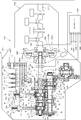
- FIG. 1 is a block diagram of the shift control system
- FIG. 2 is a configuration diagram of the shift control system.
- the shift control system 1001 of the embodiment of FIG. 1 and FIG. 2 that realizes the present invention controls a so-called seamless shift transmission 1003 and a start clutch 1005 that shift by changing over the meshing clutch while transmitting a driving force. Shift control is performed by a controller 1007 as a unit.
- the transmission 1003 includes meshing clutches 47, 49, and 51, and can be switched by a shift actuator 1009.
- the shift actuator 1009 is composed of, for example, an electric motor, is attached to the input shaft 119a of the shift drum 119, and is connected to the output port side of the controller 1007 via a drive circuit (not shown).
- the starting clutch 1005 is adapted to be tightened and adjusted by a clutch / actuator 1011.
- the starting clutch 1005 is provided between the crank shaft 1015 of the engine 1013 and the main shaft 3 of the transmission 1003, and transmits the output of the engine 1013 to the transmission 1003 so as to be intermittent.
- the starting clutch 1005 can adjust the output from the engine 1013 by adjusting the fastening of the pair of friction members 1019a and 1019b with the spring 1021.
- the spring 1021 is configured such that the movable sleeve 1023a is coupled to the inner diameter side, and the movable sleeve 1023a is adjusted to move in the axial direction with respect to the fixed sleeve 1023b.
- a clutch / actuator 1011 composed of a solenoid is provided on the fixed sleeve 1023b side, and the movable sleeve 1023a is moved in the axial direction against the urging force of the spring 1021 by energizing control of the clutch / actuator 1011. Yes.
- the clutch actuator 1011 is connected to the output port side of the controller 1007 via a drive circuit (not shown).
- the clutch / actuator 1011 is separated from the fixed sleeve 1023b, but the clutch / actuator 1011 and the fixed sleeve 1023b are integrally formed.
- the starting clutch 1005 can be configured to be engaged and controlled by an electrically controlled hydraulic actuator or the like.
- the controller 1007 is constituted by a microcomputer, for example, and includes a CPU, a ROM, a RAM, and the like.
- An input / output rotation speed sensor 1025 and an output / output rotation speed sensor 1027 are connected to an input port of the controller 1007, and a shift instruction detection sensor 1029, an engine rotation speed sensor 1031, an accelerator opening sensor 1033, and a vehicle speed sensor 1035 are connected.
- a shift instruction detection sensor 1029, an engine rotation speed sensor 1031, an accelerator opening sensor 1033, and a vehicle speed sensor 1035 are connected. Has been.
- the input / output rotational speed sensor 1025 detects the input rotational speed of the start clutch 1005 and inputs it to the control unit, and detects the rotational speed of the crankshaft 1015.
- the output / output rotation speed sensor 1027 detects the output rotation speed of the start clutch 1005 and inputs it to the controller 1007, and detects the rotation speed of the main shaft 3.
- the shift instruction detection sensor 1029 detects a manual or automatic shift instruction signal and inputs it to the controller 1007.
- the shift instruction detection sensor 1029 detects the operation signal when the shift lever is operated in the manual mode of the shift lever, for example, and inputs the operation signal to the controller 1007 as the operation signal of the shift lever. To do.
- the automatic shift instruction signal is based on the engine speed, the accelerator opening, and the vehicle speed input to the controller 1007, and the engine speed detection signal from the engine speed sensor 1031, the accelerator opening sensor 1033, and the vehicle speed sensor 1035.
- an appropriate gear position is calculated based on the input of the accelerator opening detection signal and the vehicle speed detection signal.
- the shift can be switched manually or automatically.
- the shift can be switched only manually or automatically.
- the controller 1007 When a shift instruction signal is input to the controller 1007, the controller 1007 gradually decreases the fastening force of the transmission clutch 1005 under the control of the clutch actuator 1011. When this difference causes a difference in the input / output rotational speed of the starting clutch 1005 input by the input / output rotational speed sensor 1025 and the output / output rotational speed sensor 1027, the meshing clutch 47, 49, 51 is selectively switched.
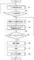
- FIG. 3 is a flowchart of the shift control system.
- step S1 (hereinafter abbreviated as “S” from the beginning of step S), a shift instruction signal is read by the process of “reading a shift instruction”. In this reading, a manual or automatic shift instruction signal is read and the process proceeds to S2.
- S2 it is determined whether or not there is a shift instruction signal from the read signal by the determination process of “There is a shift instruction?”. If there is a shift instruction (YES), the process proceeds to S3, and if there is no shift instruction (NO), the process returns to S1.
- the controller 1007 controls the energization of the clutch / actuator 1011 to adjust the movement of the movable sleeve 1023a toward the fixed sleeve 1023b by the process of “decrease of the starting clutch engaging force”, and the engaging force of the starting clutch 1005 is determined. Is gradually decreased, and the process proceeds to S4.
- the controller 1007 controls energization of the shift actuator 1009 by the “shift” process, and selectively switches the meshing clutches 47, 49, 51 in accordance with the shift instruction signal, and the process proceeds to S8.
- the time between the start of lowering the engagement force of the starting clutch 1005 by the clutch / actuator 1011 and the start of switching of the meshing clutches 47, 49, 51 by the shift actuator 1009 is less than 1 second, which exceeds 0 seconds. Do.
- the transmission control system that shifts the gears by switching the meshing clutches 47, 49, and 51 while transmitting the driving force allows the driving force to be interrupted and the engine speed and the acceleration delay to be suppressed while suppressing the shift shock and acceleration delay. More than necessary slipping or shock of the clutch due to inconsistency with the vehicle speed can be suppressed.
- the transmission 1003 selectively switches each meshing clutch of a plurality of shift gears supported by the main shaft 3 and the counter shaft 5 that are driving force transmission shafts so as to be relatively rotatable under a driving force transmission state.
- the transmission output from the starting clutch is then shifted and output.
- a plurality of meshing clutches 47, 49, 51 of the transmission 1003 are provided on the main shaft 3 so as to be movable in the axial direction.
- a gear 27, a fourth speed gear 25 and a sixth speed gear 29 are arranged, and the first speed gear 19 and the third speed gear 23 are arranged on the counter shaft 5 and selectively meshed with either of the transmission gears on both sides.
- Clutch rings 59, 61, 63 are provided for coupling to the drive output shaft.
- the shift actuator 1009 switches the selective engagement of the clutch rings 59, 61, 63 with respect to the transmission gear.
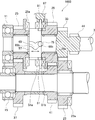
- FIG. 4 is an enlarged cross-sectional view of the main part of the transmission.
- the transmission 1003 includes a main shaft 3, a counter shaft 5, and an idler shaft 7 as driving force transmission shafts.
- the main shaft 3 and the counter shaft 5 are rotatably supported on the transmission case 17 by bearings 9, 11, 13, 15 and the like.
- the idler shaft 7 is fixed to the mission case 17 side.
- a first speed gear 19, a second speed gear 21, a third speed gear 23, a fourth speed gear 25, a fifth speed gear 27, and a sixth speed gear 29 are fixed to the main shaft 3 and the counter shaft 5 as a multi-stage transmission gear. Or it is supported so that relative rotation is possible.
- the first gear 19 and the third gear 23 on the counter shaft 5 mesh with the output gears 31 and 33 of the main shaft 3, and the second gear 21, the fourth gear 25 and the fifth gear on the main shaft 3.
- the 27th and 6th speed gears 29 mesh with the input gears 35, 37, 39, and 41 of the counter shaft 5, respectively.
- the reverse idler 43 on the idler shaft 7 is arranged so as to be able to mesh with the output gear 44 on the main shaft 3 and the input gear 45 on the counter shaft 5 by axial movement.
- the first speed gear 19, the second speed gear 21, the third speed gear 23, the fourth speed gear 25, the fifth speed gear 27, and the sixth speed gear 29 are connected to the main gear by a plurality of first to third meshing clutches 47, 49, 51. Coupled to the shaft 3 or the counter shaft 5, it is possible to output a shift from the main shaft 3 to the counter shaft 5.
- the first to third meshing clutches 47, 49, 51 are configured to change the plurality of first gear clutches 47, 49, 51 to the upper stage by changing the plurality of first to third meshing clutches 47, 49, 51. It has become. That is, the first speed gear 19, the second speed gear 21, the third speed gear 23, the fourth speed gear 25, the fifth speed gear 27, and the sixth speed gear 29, which are a plurality of speed change gears, are included in the first to third meshing clutches 47. , 49, 51 are arranged so as to change the speed.
- the shift from the first gear 19 to the second gear 21 is performed by changing the plurality of first and second meshing clutches 47 and 49.
- the first to third meshing clutches 47, 49, 51 basically have the same structure, and include clutch cam rings 53, 55, 57, clutch rings 59, 61, 63, clutch rings 59, 61, 63 and clutch teeth 47a, 47b, 49a, 49b, 51a, 51b, 19a, 21a, 23a, 25a, 27a, 29a formed on the opposing surfaces of the first speed gear 19 to the sixth speed gear 29. .
- the clutch rings 59, 61, 63 are engaged and moved in the axial direction of the main shaft 3 and the counter shaft 5 to cause clutch teeth 47a, 47b, 49a, 49b, 51a, 51b, 19a, 21a, 23a, Coupling for shifting output is performed by selective engagement of 25a, 27a, and 29a.
- the clutch cam rings 53, 55, 57 of the first to third meshing clutches 47, 49, 51 are formed with U-shaped cam grooves 65, 67, 69.
- the clutch cam ring 53 of the first meshing clutch 47 is coupled to the counter shaft 5 and can rotate integrally.
- Clutch cam rings 55 and 57 of the second and third meshing clutches 49 and 51 are coupled to the main shaft 3 and can rotate integrally.
- the clutch rings 59, 61, 63 of the first to third meshing clutches 47, 49, 51 are fitted on the outer periphery of the clutch cam rings 53, 55, 57, and are movable in the axial direction. ing.
- Cam protrusions 71, 73, 75 are formed on the inner periphery of the clutch rings 59, 61, 63, and are fitted and guided in cam grooves 65, 67, 69.
- the clutch ring 59 and the reverse idler 43 are formed with circumferential recesses 81 and 83 into which shift forks 77 and 79 described later are fitted.
- the input gear 45 is further formed on the outer periphery of the clutch ring 59.
- the clutch rings 61 and 63 are formed with circumferential ridges 89 and 91 into which shift forks 85 and 87 described later are fitted.
- the first to third meshing clutches 47, 49, 51 are selectively operated by the shift operation unit 93.
- the reverse idler 43 is also operated by the speed change operation unit 93.
- the speed change operation unit 93 is provided in the mission case 17, and includes a plurality of shift forks 77, 79, 85, 87, a plurality of shift rods 103, 105, 107, 109, and shift arms 111, 113, 115, 117 and a shift drum 119 are provided.
- Shift forks 77, 79, 85, 87 are provided for each of the first to third meshing clutches 47, 49, 51 and the reverse idler 43, and each meshing clutch 47, 49, 51, reverse idler 43 is linked.
- Shift rods 103, 105, 107, 109 support shift forks 77, 79, 85, 87.
- the shift arms 111, 113, 115, and 117 are coupled to the shift rods 103, 105, 107, and 109.
- the shift drum 119 includes shift grooves 120, 121, 123, and 125, and the front end protrusions of the shift arms 111, 113, 115, and 117 are engaged with the shift grooves 120, 121, 123, and 125. .
- uneven portions 127 and 129 and check portions 131 and 133 are provided between the shift fork 99 side and the mission case 17 side, but the illustration is omitted.
- the uneven portions 127 and 129 are formed in the shift forks 95 and 97, and are provided with mountain-shaped positioning recesses 127a, 127b, 127c, 129a, 129b, and 129c.
- the positioning recesses 127a and 129a correspond to the neutral positions, and the positioning recesses 127b, 127c, 129b and 129c correspond to the coast meshing positions.
- the check portions 131 and 133 are supported on the mission case 17 side, and the check balls 131a and 133a are urged by the check springs 131b and 133b, and are engaged with the uneven portions 127 and 129 with an elastic force. .
- the first to third meshing clutches 47, 49, 51 can be positioned to the neutral position and the coast meshing position.
- the output of the transmission 1003 is performed from the front differential device 137 that meshes with the output gear 135 of the counter shaft 5.
- the shift drum 119 is rotationally driven by a shift motor (not shown) based on the manual operation signal of the shift lever or the accelerator opening and the vehicle speed signal by the operation of the accelerator pedal, the shift The shift rods 103, 105, 107, and 109 are selectively driven in the axial direction via any one of the shift arms 111, 113, 115, and 117 by the guides of the grooves 120, 121, 123, and 125.
- the first to third meshing clutches 47, 49, 51, or the reverse idler via any of the shift forks 77, 79, 85, 87. 43 is selected.
- the first speed gear 19 to the sixth speed gear 29 and the reverse idler 43 are selectively operated, and shift up, shift down, and reverse can be changed.
- the guide portion G includes the cam grooves 65, 67, 69 and the cam protrusions 71, 73, 75 in the first to third meshing clutches 47, 49, 51 as described above. Due to the cam grooves 65, 67, 69 and cam protrusions 71, 73, 75, the driving gear and the coasting torque are supplied to the first speed gear 19 at the coast engagement position of the first to third engagement clutches 47, 49, 51. 2nd speed gear 21, 3rd speed gear 23, 4th speed gear 25, 5th speed gear 27, 6th speed gear 29, coasting only at the disengagement standby position moved from the coast engagement position to the disengagement side The meshing can be guided in the neutral direction by directional torque.
- the guide portion G includes a moving force transmission mechanism M in the speed change operation portion 93, and a driving slope F described later is provided only on the positive driving torque transmission side of the first to third meshing clutches 47, 49, 51. ing.
- the driving slope F can generate a moving force that moves the clutch rings 59, 61, 63 of the first to third meshing clutches 47, 49, 51 to the disengagement standby position by the drive torque.
- the slope F may be provided on the gear side clutch teeth, and the same function can be obtained.
- FIGS. 5 and 6 are development views showing cam grooves and cam projections
- FIGS. 7 and 8 are perspective views showing the relationship between the clutch cam ring and the clutch ring
- FIG. 9 shows the clutch cam ring
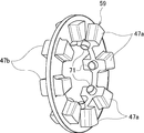
- FIG. 10 is a perspective view showing a clutch ring.
- a plurality of cam grooves 65, 67, 69 are formed on the outer peripheral surface of the clutch cam ring 53, 55, 57 at equal intervals in the circumferential direction.
- the cam grooves 65, 67, and 69 are formed with V-shaped portions 65a, 67a, and 69a at the center in the axial direction including a portion corresponding to the neutral, and flat portions 65b, 67b, and 69b are formed on both sides thereof. Is.
- the cam protrusions 71, 73, 75 project radially from the inner periphery of the clutch rings 59, 61, 63 at regular intervals in the circumferential direction, and are fitted into the cam grooves 65, 67, 69, respectively, so that they are guided. It has become.
- the cam protrusions 71, 73, 75 are positioned on the flat portions 65b, 67b, 69b, and drive torque and coasting torque are generated.
- the first speed gear 19, the second speed gear 21, the third speed gear 23, the fourth speed gear 25, the fifth speed gear 27, and the sixth speed gear 29 can be transmitted.
- the cam protrusions 71, 73, 75 are located at the V-shaped portions 65a, 67a, 69a. Torque can guide the meshing in the neutral direction.
- FIG. 11 and 12 are schematic views showing the relationship between the shift fork, the check unit, and the meshing clutch
- FIG. 13 is an exploded view of the main part of the clutch ring
- FIG. 14 shows the meshing of the dog clutch.
- (A) is a coast part engagement position
- (b) is a principal part expanded view which shows a standby mesh position.
- 11 to 14 describe the third meshing clutch. The same applies to the first and second meshing clutches, and a duplicate description is omitted.
- the third meshing clutch 51 includes the clutch teeth 51a and 51b of the clutch ring 63 and the clutch teeth 25a and 29a of the fourth speed gear 25 and the sixth speed gear 29 in the circumferential direction.
- the arrangement has a mutual spacing greater than the tooth width.
- the circumferential meshing surfaces of the clutch teeth 51a, 51b, 25a, and 29a are inclined so that the roots of the teeth are slightly thinner.
- the driving slope F is formed on the meshing surface that receives the driving torque.
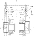
- FIG. 15 is a schematic diagram showing the meshing of the fourth gear of the transmission gear at the time of shift-up, and FIG.
- FIG. 16 is a schematic diagram showing the position of waiting for disengagement of the four-speed clutch ring of the transformer gear at the time of shift-up.
- FIG. 18 is a schematic diagram when shifting to the fifth speed is completed, and
- FIG. 18 is a schematic diagram showing that the fourth speed and the fifth speed are neutral at the time of shift down.
- the shift up from the fourth speed (lower stage) to the fifth speed (upper stage) will be mainly described.
- the arrow in the drive direction indicates that the main shaft 3 rotates counterclockwise when viewed from the right in the figure.
- FIG. 15 to FIG. 18 show the movement at the time of shifting up. Since the drive torque is applied to the 4-speed clutch teeth 25a in FIG. 15, the clutch ring 63 is in the disengagement standby position as shown in FIG. That is, the protrusion 75 of the clutch ring 63 at the fourth speed position is located on the slope of the cam groove 69. At this time, when a shift-up operation to the fifth speed is performed by the rotation of the shift drum 119, the shift groove 123 works, and the clutch ring 61 is moved via the shift arm 115, the shift rod 107, and the shift fork 85. Operated. By this operation, the clutch ring 61 is engaged with the fifth gear 27 and the fourth gear 25 and the fifth gear 27 are simultaneously engaged.
- a feature of the embodiment of the present invention is that when the clutch rings 59, 61, 63 move in the axial direction, they rotate in the same direction as the main shaft 3 or the counter shaft 5 by the action of the inclined surfaces of the cam grooves 65, 67, 69.
- the rotation of the lower clutch rings 59, 61, 63 relative to the cam rings 53, 55, 57 is delayed, and the rotation of the upper clutch rings 59, 61, 63 precedes.
- the relative speed of the clutch teeth 19a, 21a, 23a, 25a, 27a, 29a of the lower and upper gears rotating is eliminated to allow double meshing, and a synchronizing action is generated to alleviate the shift shock.
- the clutch ring 63 Even when the drive torque is working, if there is no slope F, the clutch ring 63 is not positioned at the disengagement standby position. However, even in this case, the clutch ring 63 can be forcibly moved in the neutral direction by transmission of force from the shift mechanism at the fifth speed position.
- the slope F is not essential for the present invention, and is intended to make shifting more smooth.
- the shift operation is performed by the shift grooves 120, 121, 123, and 125 (cylindrical cams) of the shift drum 119.
- the planar cam or each shift rod is controlled by a controlled hydraulic pressure, electric motor, air pressure, or the like. Even if driven, the present invention is established. [Shift down 5th gear ⁇ 4th gear] When decelerating, there is no need for a seamless shift like during acceleration. This is because the deceleration is mainly handled by the brake, and the output from the engine is basically not related, so there is no problem even if the drive torque or engine brake torque from the engine is interrupted.
- the present embodiment is characterized in that the mode of meshing transition is different between shift-up and shift-down. This is due to the fact that the upper and lower shift rings 61 and 63 are independent and the cooperating shape of the shift grooves 125 and 123 of the cylindrical cam 119.
- FIG. 19 is a diagram illustrating the operation of the drum groove during shift-up and shift-down.
- the shift arm 117 and the shift arm 115 are at the positions 115a and 117a shown in FIG.
- the shift drum 119 rotates from the top to the bottom of the figure for shifting up, the inclined surface 123a of the shift groove 123 moves the shift arm 115 from the position 115b1 to 115b2, 115c.
- double meshing occurs, and the shift arm 117 automatically moves from the position 117b1 position to the position 1172 by the action of the inclined surface of the cam groove 69 of the cam ring 57, and becomes neutral.
- the shift drum 119 rotates to shift to the position 117C. This completes the shift-up from the fourth speed to the fifth speed.
- the shift arm 115 shifts from the position 115c to the position 115b1, and becomes neutral as shown in FIG.
- the clutch ring 61 is operated in the right direction in the figure via the shift fork 85 to shift up, and at the same time, the shift ring 91 is operated in the left direction from the shift fork 87.
- the cam groove 69 connected to the main shaft 3 is rotated faster by the moving speed of the projection 75 on the fourth speed side and the curved slope effect of the cam groove 69.
- the rotation of the fourth speed gear 25 is relatively slower than the rotation of the main shaft 3 and approaches the rotation of the fifth speed gear 27.
- the rotation speed of the 5th-speed projection 73 is reduced by the cam groove 67, and the rotation speed of the 5th-speed gear 27 that rotates in the same manner as the projection 73 approaches the rotation of the 4th-speed gear 25.
- the synchro effect is generated by the above operation.
- the engagement of the start clutch 1005 can be completed in a situation where the slip speed difference of the start clutch 1015 according to the shift stage is extremely small, and a smooth shift with little shock and almost no torque interruption can be performed. it can.
- Such an action is the same in the other stage 1st speed ⁇ 2nd speed, 2nd speed ⁇ 3rd speed, 3rd speed ⁇ 4th speed, 5th speed ⁇ 6th speed, and the cam groove according to the shift speed.
- the slipping speed of the starting clutch can be controlled so that the synchro function by the protrusions can work properly.
Landscapes
- Engineering & Computer Science (AREA)
- General Engineering & Computer Science (AREA)
- Mechanical Engineering (AREA)
- Control Of Transmission Device (AREA)
- Hydraulic Clutches, Magnetic Clutches, Fluid Clutches, And Fluid Joints (AREA)
Abstract
Description
結力を低下させ検出される発進クラッチ1005の入出力回転速度に差が生じた時点でシフト・アクチュエータ1009により噛合いクラッチ47、49、51の選択的な切り替えを行わせる制御部1007とを備えることにより実現した。
図1は、変速制御システムのブロック図、図2は、変速制御システムの構成図である。
[変速制御及び発進クラッチ制御]
図3は、変速制御システムのフローチャートである。
[シームレス・シフト]
ここで、トランス・ミション1003のシームレス・シフトの構造及び作用を説明する。
[シフト・アップ]
図15は、シフト・アップ時トランス・ミションの4速ギヤ噛み合いを示す概略図、図16は、シフト・アップ時トランス・ミションの4速クラッチ・リングの離脱待機の位置を示す概略図、図17は、5速に変速終了時の概略図、図18は、シフト・ダウン時、4速5速がニュートラルであることを示す概略図である。
図15~図18にシフト・アップ時の動きを示す。図15の4速のクラッチ歯25aにはドライブ・トルクが付加されているため前記したようにクラッチ・リング63は斜面Fの作用により図16のように離脱待機位置となる。つまり4速位置にあるクラッチ・リング63の突起75はカム溝69の斜面に位置することとなる。このときシフト・ドラム119の回転により5速へのシフト・アップ操作が行われると、シフト溝123が働き、シフト・アーム115、シフト・ロッド107、シフト・フォーク85を介してクラッチ・リング61が操作される。この操作によりクラッチ・リング61が5速ギヤ27に噛み合い、4速ギヤ25及び5速ギヤ27が同時噛合いとなる。
[エンジンブレーキが働いているときのシフト・アップ]
エンジンブレーキが作用しているときシフト・アップすると、4速位置にあるクラッチ・リング63は待機位置に位置しない状態で変速が行われる。このときシフト・アップ操作によりクラッチ・リング61が5速ギヤ27に噛み合い、4速に更なるコースティング・トルクが働くが、4速位置のクラッチ・リング63は離脱待機位置に無いため、ニュートラル方向へのスラスト分力は発生しない。
[シフト・ダウン 5速→4速]
減速時は加速時のような、シームレス・シフトの必要性は無い。減速は主にブレーキにより受け持たれ、エンジンからの出力は基本的に関係しないから、エンジンからの駆動トルクやエンジンブレーキトルクが途切れても問題ないためである。このため通常のマニアルトランス・ミションと同じように、まず上段の5速位置にあるクラッチ・リング61を図18に示すニュートラルに移動させ動力を遮断し、次にクラッチ・リング63を4速ギヤ25を噛み合わせることでシフト・ダウンする。
以下このようにシフト・アップとシフト・ダウンとで変速形態を異ならせる機構について図19により説明する。図19は、シフト・アップ、シフト・ダウンのときのドラム溝の作動説明である。
[シフト・ダウン 5速→4速]
5速でクラッチが噛み合っているとき、シフト・フォーク117はチェック部133により図2に示すようにニュートラル位置に保持されている。シフト・ドラム119が回転し、シフト溝125がシフト・アーム117に対し、図19の位置117b2にあって軸方向の遊びがあっても、上記チェック部133によりシフト・アーム117は位置117b2においてニュートラルに保持される。
[変速ショック緩和メカニズム]
かかるトランス・ミッション1003の変速制御及び前記発進クラッチ制御による変速ショック緩和のメカニズムをさらに具体的に説明する。この場合、説明を簡単にするため、4速→5速へのシフト・アップ時について説明する。
1003 トランス・ミション
1005 発進クラッチ
1007 コントローラ(制御部)
1009 シフト・アクチュエータ
1011 クラッチ・アクチュエータ
1025 イン・プット回転速度センサ
1027 アウト・プット回転速度センサ
3 メイン・シャフト(駆動力伝達軸)
5 カウンタ・シャフト(駆動力伝達軸)
19 1速ギヤ(変速ギヤ)
21 2速ギヤ(変速ギヤ)
23 3速ギヤ(変速ギヤ)
25 4速ギヤ(変速ギヤ)
27 5速ギヤ(変速ギヤ)
29 6速ギヤ(変速ギヤ)
47 第1の噛合いクラッチ
49 第2の噛合いクラッチ
51 第3の噛合いクラッチ
59、61、63 クラッチ・リング
G ガイド部
Claims (4)
- 駆動力を伝達しながら噛合いクラッチの切り替えにより変速する変速制御システムであって、
エンジンからのトルクを締結調整により伝達出力する発進クラッチと、
駆動力伝達軸に相対回転自在に支持された複数段の変速ギヤの各噛合いクラッチが駆動力伝達状態下で選択的に切り替えられて前記発進クラッチからの伝達出力を変速出力するトランス・ミションと、
前記発進クラッチを締結調整するクラッチ・アクチュエータと、
前記噛合いクラッチをシフト指示信号により切り替えるシフト・アクチュエータと、
前記発進クラッチの入力回転速度を検出するイン・プット回転速度センサ及び出力回転速度を検出するアウト・プット回転速度センサと、
前記シフト指示信号の入力により前記クラッチ・アクチュエータを制御して前記発進クラッチの締結力を低下させ前記検出される発進クラッチの入出力回転速度に差が生じた時点で前記シフト・アクチュエータにより前記噛合いクラッチの選択的な切り替えを行わせる制御部と、
を備えたことを特徴とする変速制御システム。 - 請求項1記載の変速制御システムであって、
前記制御部は、前記クラッチ・アクチュエータによる発進クラッチの締結力を低下開始から前記シフト・アクチュエータによる噛合いクラッチの切り替え開始までの間を0秒を上回る1秒未満で行う、
ことを特徴とする変速制御システム。 - 請求項1又は2記載の変速制御システムであって、
前記制御部は、前記発進クラッチの入出力回転速度に差が生じた時点で前記クラッチ・アクチュエータの制御を前記切り替えが完了するまで固定する、
ことを特徴とする変速制御システム。 - 請求項1~3の何れか1項記載の変速制御システムであって、
前記噛合いクラッチは、前記駆動力伝達軸に軸方向移動可能に複数備えられ軸方向の両サイドに2速以上はなれて前記変速ギヤがそれぞれ配置され各両サイドの何れかの変速ギヤと選択的に噛み合って前記駆動出力軸に結合させるクラッチ・リングを備え、
前記シフト・アクチュエータは、前記クラッチ・リングの前記変速ギヤに対する選択的な噛み合いを切り替え、
前記下段と上段との変速ギヤに前記何れか一対のクラッチ・リングが各別に同時噛合いしたとき前記下段と上段との変速ギヤに噛合い方向と噛合い解除方向との異なる方向の軸力を各別に生じさせるガイド部を前記各クラッチ・リングと前記駆動力伝達軸との間に設けた、
ことを特徴とする変速制御システム。
Priority Applications (3)
| Application Number | Priority Date | Filing Date | Title |
|---|---|---|---|
| EP12890772.2A EP2942549A4 (en) | 2012-12-25 | 2012-12-25 | Transmission control system |
| JP2014553875A JP6180438B2 (ja) | 2012-12-25 | 2012-12-25 | 変速制御システム |
| PCT/JP2012/008265 WO2014102855A1 (ja) | 2012-12-25 | 2012-12-25 | 変速制御システム |
Applications Claiming Priority (1)
| Application Number | Priority Date | Filing Date | Title |
|---|---|---|---|
| PCT/JP2012/008265 WO2014102855A1 (ja) | 2012-12-25 | 2012-12-25 | 変速制御システム |
Publications (1)
| Publication Number | Publication Date |
|---|---|
| WO2014102855A1 true WO2014102855A1 (ja) | 2014-07-03 |
Family
ID=51020022
Family Applications (1)
| Application Number | Title | Priority Date | Filing Date |
|---|---|---|---|
| PCT/JP2012/008265 Ceased WO2014102855A1 (ja) | 2012-12-25 | 2012-12-25 | 変速制御システム |
Country Status (3)
| Country | Link |
|---|---|
| EP (1) | EP2942549A4 (ja) |
| JP (1) | JP6180438B2 (ja) |
| WO (1) | WO2014102855A1 (ja) |
Cited By (6)
| Publication number | Priority date | Publication date | Assignee | Title |
|---|---|---|---|---|
| WO2016152781A1 (ja) * | 2015-03-20 | 2016-09-29 | アイシン・エーアイ株式会社 | 車両の動力伝達制御装置 |
| JP2018048673A (ja) * | 2016-09-20 | 2018-03-29 | 株式会社イケヤフォ−ミュラ | 変速制御システム |
| JP2018071628A (ja) * | 2016-10-27 | 2018-05-10 | ジヤトコ株式会社 | 自動変速機 |
| JP2020085065A (ja) * | 2018-11-20 | 2020-06-04 | ジヤトコ株式会社 | シームレスシフト機構 |
| US10746263B2 (en) | 2016-12-12 | 2020-08-18 | Toyota Motor Engineering & Manufacturing North America, Inc. | Automatic transmission with electric synchronization |
| WO2023238946A1 (ja) * | 2022-06-09 | 2023-12-14 | ヤマハ発動機株式会社 | 変速装置 |
Citations (3)
| Publication number | Priority date | Publication date | Assignee | Title |
|---|---|---|---|---|
| JP2002257225A (ja) * | 2001-02-27 | 2002-09-11 | Hitachi Ltd | 自動変速機の制御装置 |
| JP2003172378A (ja) * | 2001-12-07 | 2003-06-20 | Hitachi Ltd | 自動変速機の制御装置及び制御方法 |
| JP2011020570A (ja) * | 2009-07-16 | 2011-02-03 | Nissan Motor Co Ltd | ハイブリッド車両の制御装置 |
Family Cites Families (7)
| Publication number | Priority date | Publication date | Assignee | Title |
|---|---|---|---|---|
| JPS6430840A (en) * | 1987-07-27 | 1989-02-01 | Toyota Motor Corp | Control device for driving system of vehicle |
| JPH026235A (ja) * | 1988-06-24 | 1990-01-10 | Diesel Kiki Co Ltd | 自動変速装置 |
| JP2004084912A (ja) * | 2002-08-29 | 2004-03-18 | Toyota Motor Corp | 自動クラッチ付き有段変速機の変速制御装置 |
| BRPI0412454B1 (pt) * | 2003-07-08 | 2017-02-14 | Zeroshift Ltd | sistema de transmissão |
| GB0609333D0 (en) * | 2006-05-11 | 2006-06-21 | Zeroshift Ltd | Engagement member actuator control |
| JP5707119B2 (ja) * | 2010-12-17 | 2015-04-22 | 株式会社イケヤフォ−ミュラ | トランスミッション |
| EP2650560B1 (en) * | 2010-11-19 | 2020-10-21 | Ikeya Formula Co., Ltd. | Transmission and shift control system |
-
2012
- 2012-12-25 JP JP2014553875A patent/JP6180438B2/ja active Active
- 2012-12-25 WO PCT/JP2012/008265 patent/WO2014102855A1/ja not_active Ceased
- 2012-12-25 EP EP12890772.2A patent/EP2942549A4/en not_active Withdrawn
Patent Citations (3)
| Publication number | Priority date | Publication date | Assignee | Title |
|---|---|---|---|---|
| JP2002257225A (ja) * | 2001-02-27 | 2002-09-11 | Hitachi Ltd | 自動変速機の制御装置 |
| JP2003172378A (ja) * | 2001-12-07 | 2003-06-20 | Hitachi Ltd | 自動変速機の制御装置及び制御方法 |
| JP2011020570A (ja) * | 2009-07-16 | 2011-02-03 | Nissan Motor Co Ltd | ハイブリッド車両の制御装置 |
Non-Patent Citations (2)
| Title |
|---|
| RACECAR ENGINNERING, June 2005 (2005-06-01), Retrieved from the Internet <URL:www.racecar-engineering.com> |
| See also references of EP2942549A4 * |
Cited By (8)
| Publication number | Priority date | Publication date | Assignee | Title |
|---|---|---|---|---|
| WO2016152781A1 (ja) * | 2015-03-20 | 2016-09-29 | アイシン・エーアイ株式会社 | 車両の動力伝達制御装置 |
| JP2018048673A (ja) * | 2016-09-20 | 2018-03-29 | 株式会社イケヤフォ−ミュラ | 変速制御システム |
| JP2018071628A (ja) * | 2016-10-27 | 2018-05-10 | ジヤトコ株式会社 | 自動変速機 |
| US10746263B2 (en) | 2016-12-12 | 2020-08-18 | Toyota Motor Engineering & Manufacturing North America, Inc. | Automatic transmission with electric synchronization |
| JP2020085065A (ja) * | 2018-11-20 | 2020-06-04 | ジヤトコ株式会社 | シームレスシフト機構 |
| JP7301460B2 (ja) | 2018-11-20 | 2023-07-03 | ジヤトコ株式会社 | シームレスシフト機構 |
| WO2023238946A1 (ja) * | 2022-06-09 | 2023-12-14 | ヤマハ発動機株式会社 | 変速装置 |
| WO2023238315A1 (ja) * | 2022-06-09 | 2023-12-14 | ヤマハ発動機株式会社 | 変速装置 |
Also Published As
| Publication number | Publication date |
|---|---|
| EP2942549A4 (en) | 2017-08-02 |
| EP2942549A1 (en) | 2015-11-11 |
| JPWO2014102855A1 (ja) | 2017-01-12 |
| JP6180438B2 (ja) | 2017-08-16 |
Similar Documents
| Publication | Publication Date | Title |
|---|---|---|
| JP5707119B2 (ja) | トランスミッション | |
| US8052573B2 (en) | Vehicle shift control apparatus | |
| CN103299104B (zh) | 变速器及变速控制系统 | |
| JP5840670B2 (ja) | 変速制御装置 | |
| JP5822615B2 (ja) | 自動クラッチ制御装置およびその変速制御方法 | |
| JP2012127471A5 (ja) | ||
| JP6180438B2 (ja) | 変速制御システム | |
| JP2003314635A (ja) | 自動変速機 | |
| JP5863379B2 (ja) | デュアルクラッチ式自動変速機およびその変速制御方法 | |
| WO2017122682A1 (ja) | 車両用デュアルクラッチ式変速機の制御装置 | |
| JP6251585B2 (ja) | トランスミッション | |
| JP2010281423A (ja) | 同期噛合式変速機の変速装置及びその変速方法 | |
| JP5892763B2 (ja) | デュアルクラッチ式自動変速機およびその変速制御方法 | |
| EP3220015B1 (en) | Variable speed control system | |
| JP2011196512A (ja) | 車両の動力伝達制御装置 | |
| JP6248654B2 (ja) | クラッチ圧制御装置 | |
| JP2014122676A (ja) | 坂道発進補助システム | |
| JP6775821B2 (ja) | 変速制御システム | |
| JP6385522B2 (ja) | 坂道発進補助装置 | |
| JP6669835B2 (ja) | トランスミッション | |
| JPS632736A (ja) | 車両用自動変速装置 | |
| JP2010096211A (ja) | 変速機の制御装置 | |
| JP6178745B2 (ja) | 動力伝達装置 | |
| JP2005337149A (ja) | 自動変速機の制御装置 | |
| JP2019074178A (ja) | 自動変速機 |
Legal Events
| Date | Code | Title | Description |
|---|---|---|---|
| 121 | Ep: the epo has been informed by wipo that ep was designated in this application |
Ref document number: 12890772 Country of ref document: EP Kind code of ref document: A1 |
|
| ENP | Entry into the national phase |
Ref document number: 2014553875 Country of ref document: JP Kind code of ref document: A |
|
| NENP | Non-entry into the national phase |
Ref country code: DE |
|
| WWE | Wipo information: entry into national phase |
Ref document number: 2012890772 Country of ref document: EP |
|
| WWW | Wipo information: withdrawn in national office |
Ref document number: 2012890772 Country of ref document: EP |