WO2014102921A1 - Composant de câblage résistant à la chaleur et son procédé de fabrication - Google Patents
Composant de câblage résistant à la chaleur et son procédé de fabrication Download PDFInfo
- Publication number
- WO2014102921A1 WO2014102921A1 PCT/JP2012/083551 JP2012083551W WO2014102921A1 WO 2014102921 A1 WO2014102921 A1 WO 2014102921A1 JP 2012083551 W JP2012083551 W JP 2012083551W WO 2014102921 A1 WO2014102921 A1 WO 2014102921A1
- Authority
- WO
- WIPO (PCT)
- Prior art keywords
- inorganic barrier
- barrier layer
- wiring component
- wiring
- insulating resin
- Prior art date
- Legal status (The legal status is an assumption and is not a legal conclusion. Google has not performed a legal analysis and makes no representation as to the accuracy of the status listed.)
- Ceased
Links
Images


Classifications
-
- H—ELECTRICITY
- H01—ELECTRIC ELEMENTS
- H01B—CABLES; CONDUCTORS; INSULATORS; SELECTION OF MATERIALS FOR THEIR CONDUCTIVE, INSULATING OR DIELECTRIC PROPERTIES
- H01B7/00—Insulated conductors or cables characterised by their form
- H01B7/17—Protection against damage caused by external factors, e.g. sheaths or armouring
- H01B7/29—Protection against damage caused by extremes of temperature or by flame
- H01B7/292—Protection against damage caused by extremes of temperature or by flame using material resistant to heat
-
- C—CHEMISTRY; METALLURGY
- C03—GLASS; MINERAL OR SLAG WOOL
- C03C—CHEMICAL COMPOSITION OF GLASSES, GLAZES OR VITREOUS ENAMELS; SURFACE TREATMENT OF GLASS; SURFACE TREATMENT OF FIBRES OR FILAMENTS MADE FROM GLASS, MINERALS OR SLAGS; JOINING GLASS TO GLASS OR OTHER MATERIALS
- C03C3/00—Glass compositions
- C03C3/12—Silica-free oxide glass compositions
- C03C3/122—Silica-free oxide glass compositions containing oxides of As, Sb, Bi, Mo, W, V, Te as glass formers
-
- C—CHEMISTRY; METALLURGY
- C03—GLASS; MINERAL OR SLAG WOOL
- C03C—CHEMICAL COMPOSITION OF GLASSES, GLAZES OR VITREOUS ENAMELS; SURFACE TREATMENT OF GLASS; SURFACE TREATMENT OF FIBRES OR FILAMENTS MADE FROM GLASS, MINERALS OR SLAGS; JOINING GLASS TO GLASS OR OTHER MATERIALS
- C03C3/00—Glass compositions
- C03C3/12—Silica-free oxide glass compositions
- C03C3/16—Silica-free oxide glass compositions containing phosphorus
-
- C—CHEMISTRY; METALLURGY
- C03—GLASS; MINERAL OR SLAG WOOL
- C03C—CHEMICAL COMPOSITION OF GLASSES, GLAZES OR VITREOUS ENAMELS; SURFACE TREATMENT OF GLASS; SURFACE TREATMENT OF FIBRES OR FILAMENTS MADE FROM GLASS, MINERALS OR SLAGS; JOINING GLASS TO GLASS OR OTHER MATERIALS
- C03C3/00—Glass compositions
- C03C3/12—Silica-free oxide glass compositions
- C03C3/16—Silica-free oxide glass compositions containing phosphorus
- C03C3/21—Silica-free oxide glass compositions containing phosphorus containing titanium, zirconium, vanadium, tungsten or molybdenum
-
- C—CHEMISTRY; METALLURGY
- C03—GLASS; MINERAL OR SLAG WOOL
- C03C—CHEMICAL COMPOSITION OF GLASSES, GLAZES OR VITREOUS ENAMELS; SURFACE TREATMENT OF GLASS; SURFACE TREATMENT OF FIBRES OR FILAMENTS MADE FROM GLASS, MINERALS OR SLAGS; JOINING GLASS TO GLASS OR OTHER MATERIALS
- C03C8/00—Enamels; Glazes; Fusion seal compositions being frit compositions having non-frit additions
- C03C8/02—Frit compositions, i.e. in a powdered or comminuted form
-
- C—CHEMISTRY; METALLURGY
- C03—GLASS; MINERAL OR SLAG WOOL
- C03C—CHEMICAL COMPOSITION OF GLASSES, GLAZES OR VITREOUS ENAMELS; SURFACE TREATMENT OF GLASS; SURFACE TREATMENT OF FIBRES OR FILAMENTS MADE FROM GLASS, MINERALS OR SLAGS; JOINING GLASS TO GLASS OR OTHER MATERIALS
- C03C8/00—Enamels; Glazes; Fusion seal compositions being frit compositions having non-frit additions
- C03C8/02—Frit compositions, i.e. in a powdered or comminuted form
- C03C8/08—Frit compositions, i.e. in a powdered or comminuted form containing phosphorus
Definitions
- the present invention relates to a heat-resistant wiring component having a laminated structure of an inorganic resin layer and an inorganic barrier layer of a lead-free glass composition which softens and flows at a baking temperature lower than that of the prior art on a conductor wiring.
- thermoelectric element is coated with a metal, an alloy, a ceramic, a mixture of glass and a ceramic to prevent deterioration due to oxygen, moisture, chemicals, or heat.
- Patent Document 2 discloses the placement of an inorganic barrier layer on a polymer film by the atomic layer deposition (ADL) method. According to this method, a dense inorganic barrier layer can be formed with high adhesion, but on the other hand, it is necessary to carry out a film formation reaction at the molecular level multiple times within an environmentally controlled chamber, which is a problem in productivity Have. Further, in any of the examples, it was necessary to establish a method for coping with the case where a crack or a pinhole occurs in the inorganic barrier layer.
- ADL atomic layer deposition
- JP 2012-523110 gazette Japanese Patent Publication No. 2004-535514
- An object of the present invention is to provide a wiring component composed of an inorganic barrier layer, an insulating resin layer, and a conductor wiring having a crack and pinhole repair performance and excellent adhesion, and a method of manufacturing the same.
- the wiring component is characterized in that one or more insulating resin layers and one or more inorganic barrier layers are provided on the conductor wiring.
- the softening point of the inorganic barrier layer is 200 ° C. or more and less than 350 ° C.
- the 5 wt% thermal weight reduction temperature of the insulating resin layer is higher than the softening point of the inorganic barrier layer.
- the inorganic barrier layer is preferably a lead-free glass composition and contains 75 wt% or more of Ag 2 O, V 2 O 5 and TeO 2 .
- the wiring component comprised from the inorganic barrier layer which has the repair performance of a crack and a pinhole, and the outstanding adhesiveness, an insulating resin layer, and conductor wiring can be provided.
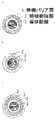
- the cross-sectional schematic diagram showing an example of the enameled wire of this invention The chart showing the heat flow rate in the temperature rising process of the differential thermal analysis (DTA) of the typical inorganic barrier layer (glass composition) in this invention.
- FIG. 1 It is a wiring component in which the insulating resin layer 2 and the inorganic barrier layer 3 of at least one or more layers are provided on the conductor wiring 1.
- the insulating resin layer 2 and / or the conductor wiring 1 is less susceptible to oxidative degradation and hydrolysis, and heat resistance and moisture resistance are improved.
- FIG. 1-a has the insulating resin layer 2 directly on the conductor wiring 1 and the inorganic barrier layer as the outermost layer.
- FIG. 1-b has the inorganic barrier layer 3 directly on the conductor wiring 1 and the organic insulating layer 2 as the outermost layer. In this configuration, corrosion of the conductor wiring 1 due to oxidation deterioration and moisture absorption is prevented. Further, since the flexible organic insulating layer 2 is provided as the outermost layer, peeling of the inorganic barrier layer 1 from the conductor wiring can be prevented.
- the insulating resin layer 2 directly on the conductor wiring 1, and then has the inorganic barrier layer, and has the insulating resin layer 2 as the outermost layer.
- the heat resistance and moisture resistance of the enameled wire are improved because the inorganic barrier layer 3 suppresses the contact of oxygen and moisture with the insulating resin layer 2 and the conductor wiring 1 of the inner layer, and the insulating resin layer 2 of the outermost layer is improved. Peeling off of the inorganic barrier layer 3 can be prevented.
- the softening point of the inorganic barrier layer 3 is 200 ° C. or more and less than 350 ° C., and the 5 wt% thermal weight reduction temperature of the insulating resin layer 2 is a wiring component using a material configuration higher than the softening point of the inorganic barrier layer. This makes it possible to form the inorganic barrier layer 3 by a simple method such as melt coating, heat lamination, heat press, etc., and when a crack or a pinhole is generated in the inorganic barrier layer, the softening point of the inorganic barrier layer Cracks and pinholes can be repaired by heating the wiring component to the above temperature.
- the above-mentioned inorganic barrier layer 3 is a lead-free glass composition, and is a low melting glass containing 75 wt% or more of Ag 2 O, V 2 O 5 and TeO 2 It is preferable from the viewpoint of environmental consideration to use
- various lead-free low-melting glasses have been proposed as low-melting glasses, but generally lead-free glasses are accompanied by a decrease in softening point. It has problems such as a decrease in thermal stability (which makes it easy to crystallize) and a decrease in chemical stability (a decrease in moisture resistance).
- the low melting point glass composition of the present invention can lower the softening point without causing any problems of crystallization and moisture resistance.
- AgO 2 and TeO 2 contribute to lowering the softening point of the glass composition, and V 2 O 5 suppresses the precipitation of metal Ag from the glass composition, and the thermal stability and chemical stability of the glass composition Contribute to improvement.
- FIG. 2 is a heat flow chart in the temperature rising process of differential thermal analysis (DTA) of a typical glass composition in the present invention.
- DTA differential thermal analysis
- the start temperature of the first endothermic peak is the glass transition temperature Tg
- the peak temperature of the first endothermic peak is the deformation point Td
- the peak temperature of the second endothermic peak is the softening point Ts
- the first exothermic start temperature is the crystallization temperature Defined as Tc.
- the observation condition of DTA was ⁇ -alumina as a reference sample, in the air, under the condition of a temperature elevation rate of 5 ° C./min.
- the inorganic barrier layer 3 contains 25 wt% or less of at least one of P 2 O 5 , BaO, K 2 O, WO 3 , MoO 3 , Fe 2 O 3 , MnO 2 , Sb 2 O 3 , and ZnO. Can be contained in These components contribute to the improvement of moisture resistance and the suppression of crystallization.
- the resistivity of the barrier layer 3 is set at an applied voltage of 100 V to 10 9 ⁇ ⁇ cm or more. Thereby, the insulation reliability of the wiring component can be improved.
- Such an inorganic barrier layer 3 is a lead-free glass composition, containing 75 wt% or more of Ag 2 O, V 2 O 5 and TeO 2, and having a content of Ag 2 O of 30 wt% or less, The content of V 2 O 5 is 25 wt% or more, and the ratio represented by the Ag 2 O content / V 2 O 5 content is 1.2 or less.
- the insulating resin layer 2 is made of polyethylene, polyvinyl chloride, polyurethane, polystyrene, hydrogenated styrene-butadiene elastomer, polyphenylene ether, phenoxy resin, polyester, polyester imide, polyamide imide, polyether imide, poly phenylene sulfide, polyether ether ketone, A single or composite material containing a resin component selected from polyimides is preferably used.
- the interface between the inorganic barrier layer 3 and the insulating resin layer 2 is joined by an anchor effect.
- the adhesion between the insulating resin layer 2 and the inorganic barrier layer 3 can be increased by forming the anchor structure.
- the anchor structure in the present invention is a structure schematically represented by the cross-sectional structure of FIG. 3 in which the interface between the insulating resin layer 2 and the inorganic barrier layer 3 has unevenness and enters each other.
- a low melting point glass dispersion layer containing a filler of the low melting point glass is formed on at least the surface of the inorganic insulating layer 2, and the inorganic barrier layer 3 is fused on the dispersion layer.
- An anchor structure can be formed by integrating the filler of the low melting point glass and the inorganic barrier layer 3.
- the inorganic barrier layer 3 is formed by a cold spray method. Irregularities are formed at the interface between the inorganic barrier layer 3 and the insulating resin layer 2 formed by the cold spray method due to the collision of the low melting point glass filler, whereby an anchor structure is formed. Further, since the inorganic barrier layer 3 formed by the cold spray method is thin, the inorganic barrier layer 3 can be prevented from peeling off even when the wiring component is bent.
- heat treatment is performed at a temperature equal to or higher than the softening point of the inorganic barrier layer 3.
- the heat treatment may be performed at the completion of the wiring component, or may be performed after the wiring component is incorporated into an electronic or electrical device.
- Transparent glass such as lead glass does not absorb laser light and infrared light
- the low melting glass used in the present invention absorbs laser light and infrared light and softens.
- the low melting point glass can be softened and cracks and pinholes can be repaired while suppressing thermal damage to the insulating resin layer 2 and peripheral parts.
- the wiring component is excellent in heat resistance and moisture resistance due to the effect of the repairable inorganic barrier layer 3.
- the shape of the conductor wiring 1 can be used as a enameled wire or wire which is a round wire, a square wire, and a stranded wire.
- FIG. 4 shows a structure in which a plurality of conductor wires are fixed by two adhesive films, and an inorganic barrier layer is provided on the outer layer thereof. It is preferable to form an anchor structure at the interface between the inorganic barrier layer and the substrate film as described above. Further, as in the case of the enameled wire and the wire, an insulating resin layer may be further formed on the inorganic barrier layer.
- the activation energy based on 5% weight loss in the present invention is one of the factors governing the heat resistance of the insulating material, and refers to the value determined by the following method.
- Thermogravimetry (TGA) of the resin is carried out under the conditions of a heating rate of 5 ° C., 10 ° C. and 20 ° C. in the atmosphere.
- the temperature (absolute temperature T5, T10, T20) at which the organic component in the resin decreases by 5 wt% under each temperature rising condition is observed. As shown in FIG.
- Activation energy (kcal / mol) 1 / a ⁇ R ⁇ 0.4567 ⁇ 1000 ⁇ ⁇ ⁇ Formula 1 (R is the gas constant, 1.987 cal / K ⁇ mol) [9] What is 0.4567 in Equation 1 Takeshi Ozawa "Nonisothermal Kinetics (1) In the Case of a Single-Element Process", Netsu Sokutei Vol. 31, (3), is a coefficient of an approximate expression for deriving activation energy by the Ozawa method described in pp. 125-132. ⁇ Calculation of heat-resistant temperature index> The heat-resistant temperature index Ti was determined by the following equation 2 using the activation energy determined as described above.
- ti is the time to reach a weight loss of 5 wt%, 20000 ⁇ 60 (minutes)
- Ea is the activation energy converted to J / mol
- R is the gas constant 8.3122621 (J / K ⁇ mol)
- Vt I is the temperature rise rate (K / min)
- Tn is the temperature (K) at which the weight loss reached 5 wt% according to the TGA observation.
- this method is called Ozawa-F lynn-Wall method.
- Example 1 low melting glasses having various compositions were produced, and the softening point and specific resistance of the glass composition were investigated.
- Glass compositions AVT 1 to 10 having the compositions shown in Table 1 described later were produced.
- the composition in the table is represented by the mass ratio of each component in terms of oxide.
- an oxide powder purity 99.9%
- B (PO 3 ) 2 barium phosphate, manufactured by Lasa Kogyo Co., Ltd. was used as the Ba source and the P source.
- Each starting material powder was mixed by the mass ratio shown to the table
- an alumina crucible was used.
- the mixing was performed in a crucible using a metal spoon to avoid moisture absorption of the raw material powder.
- the crucible containing the raw material mixed powder was placed in a glass melting furnace, and was heated and melted. The temperature was raised at 10 ° C./min, and the molten glass was maintained at a set temperature of 700 ° C. to 900 ° C. for 1 hour while stirring. Thereafter, the crucible was taken out and glass was cast in a graphite mold heated to 150 ° C.
- AVTs 1 to 10 according to the present invention (the components are at least containing Ag 2 O, V 2 O 5 and TeO 2 when expressed as oxides, Ag 2 O and V 2 O 5
- the lead-free glass composition having a total of 75 wt% or more and TeO 2 was confirmed to have a softening point Ts of 350 ° C. or less.
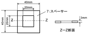
- evaluation of resistivity A 3 mm thick polytetrafluoroethylene spacer shown in FIG. 6 was produced. About 8 g of the glass rod was placed in the spacer, and heated and pressed by a vacuum press to prepare a glass plate of about 20 mm ⁇ 20 mm ⁇ 3 mm. Using this glass plate as a sample, Hiresta UP, MCP-HT450 type high resistance resistivity meter manufactured by Mitsubishi Chemical Analytech Co., Ltd. was used to measure the specific resistance at an applied voltage of 100 V. The results are shown in Table 1.
- AVTs 1 to 8 according to the present invention (the components are at least containing Ag 2 O, V 2 O 5 and TeO 2 when expressed as oxides, Ag 2 O and V 2 O 5
- the total content with TeO 2 is 75 wt% or more, the content of Ag 2 O is 30 wt% or less, the content of V 2 O 5 is 25 wt% or more, and the Ag 2 O content / V 2 O 5 content
- the lead-free glass composition having a ratio represented by an amount of 1.2 or less has a softening temperature of 350 ° C. or less and a specific resistance of 10 9 ⁇ ⁇ cm or more.
- Example 2 In the present example, the heat resistance improvement effect of the insulating resin by the inorganic barrier layer was examined.
- An AVT 2 lead-free glass composition was used for the inorganic barrier layer.
- the insulating resin polyester imide, polyamide imide, polyimide, which is a covering material of enameled wire, and polyethylene which is a wire covering material, were used.
- About 5 mg of the insulating resin was collected in a TGA aluminum pan and weighed. Then, while heating the aluminum pan on a hot plate at 300 ° C., about 180 mg of the AVT 2 lead-free glass composition was placed in the aluminum pan, the glass was melted, and the insulating resin in the aluminum pan was completely covered. This sample was used as an inorganic barrier layer sample.
- the heat-resistant temperature index indicates a value obtained by estimating the temperature at which a weight loss of 5 wt% occurs when the insulating resin is held under a constant temperature condition for 20000 hours.
- thermogravimetric analyzer TGA
- heat loss under air flow mL / 100 min
- heating rate 5 ° C / min
- 10 ° C / min 10 ° C / min
- 20 ° C / min The behavior was observed to determine the temperature at which the initial weight of the insulating resin decreased by 5 wt%.
- the heat resistance temperature index was determined by the Ozawa-F lynn-Wall method described above. The results are shown in Table 2.
- the heat resistance temperature index of Example 2 which has an inorganic barrier layer shows a value higher than that without an inorganic barrier layer, and it was confirmed that installation of an inorganic barrier layer is effective in improvement of the heat resistance of insulating resin.
- Example 3 the moisture resistance improving effect of the polyimide film which is a base material of the film wiring material was examined. Test samples are shown below.
- Base polyimide film Kaneka Corporation (R) Apical AH, 25 ⁇ m thick Bisphenol A type phenoxy resin: YP-50 manufactured by Tohto Kasei Kogyo Co., Ltd. 2-isocyanato ethyl methacrylate: manufactured by Showa Denko KK (R) Carens MOI Dibutyltin dilaurate: Wako Pure Chemical Industries, Ltd. 2,6-di-t-butyl-4-methylphenol: Wako Pure Chemical Industries, Ltd.
- a 20 cm ⁇ 20 cm polyimide film ((R) UPILEX 50S) was attached to a 20 cm ⁇ 20 cm mirror plate with a polyimide tape. About 5 g of powder of AVT 10 was placed on the polyimide film, covered with another polyimide film ((R) UPILEX 50S), and a mirror plate was placed thereon. The laminate was heated and pressed by a vacuum press to thin the AVT 10. One polyimide film was peeled off from the thinned AVT 10 to obtain a polyimide film carrying a glass layer.
- the heating condition was 280 ° C./30 minutes, and the pressurizing condition was 4 MPa after the temperature of the end plate reached 280 ° C.
- the thickness of the glass thin film layer on the polyimide film was about 50 ⁇ m.
- a 1 mm thick, 20 cm ⁇ 20 cm polytetrafluoroethylene plate was stacked thereon, and a 20 cm ⁇ 20 cm end plate was placed thereon.
- the laminate was pressed and heated by a vacuum press to bond the copper foil and the adhesive film.
- the pressing conditions were 160 ° C./30 minutes and 180 ° C./1 hour at a pressure of 1 MPa.
- Adhesive samples were prepared using adhesive films 1 and 2 respectively. (Installation of inorganic barrier layer)
- a 20 cm ⁇ 20 cm polyimide film ((R) UPILEX 50S) was attached to a 20 cm ⁇ 20 cm mirror plate with a polyimide tape.
- An adhesive sample having a primer layer thereon and a thin film glass-supporting polyimide film were placed such that the primer layer and the glass layer were in contact with each other.
- a 1 mm thick, 20 cm ⁇ 20 cm polytetrafluoroethylene plate was stacked thereon, and a 20 cm ⁇ 20 cm end plate was placed thereon.
- the laminate was pressed and heated by a vacuum press to fuse the primer layer and the glass layer.
- the pressing conditions were 280 ° C./30 minutes and the pressure was 4 MPa.
- the adhesion sample was removed from the polyimide film carrying glass, and an adhesion sample with an inorganic barrier layer was produced.
- Example 3 The adhesion after deterioration was observed to be high in Example 3 having the inorganic barrier layer.
- the peeling mode in all the samples was breakage of the adhesive film, so the base polyimide film of Comparative Example 3 having no inorganic barrier layer is considered to be deteriorated under high temperature and high humidity. It was confirmed that the installation of the inorganic barrier layer contributes to the improvement of the moisture resistance of the insulating resin.
- Example 4 The installation of the inorganic barrier layer by cold spray method was examined to the enameled wire which uses polyphenylene sulfide (PPS) as an insulating layer.
- PPS polyphenylene sulfide
- the glass powder of AVT1 was sprayed at room temperature using a Dymet 403i cold spray apparatus manufactured by OCPS.
- the glass layer was melted by irradiation with infrared light.
- unevenness was present at the interface between the PPS layer and the glass layer, and an anchor structure was confirmed.
- minute inorganic barrier layer can be formed by re-melting a glass layer after glass layer formation.
- the wiring component of the present invention is suitable for a film wiring material for automobiles, an enameled wire of a motor or a coil for a generator transformer, and the like, which are required to have high heat resistance.
- SYMBOLS 1 Conductor wiring, 2 ... Insulating resin layer, 3 ... Inorganic barrier layer, 4 ... Anchor structure, 5 ... Base material film, 6 ... Adhesion layer, 7 ... Spacer.
Landscapes
- Chemical & Material Sciences (AREA)
- Life Sciences & Earth Sciences (AREA)
- Engineering & Computer Science (AREA)
- Chemical Kinetics & Catalysis (AREA)
- General Chemical & Material Sciences (AREA)
- Geochemistry & Mineralogy (AREA)
- Materials Engineering (AREA)
- Organic Chemistry (AREA)
- Glass Compositions (AREA)
- Inorganic Insulating Materials (AREA)
- Organic Insulating Materials (AREA)
- Insulated Conductors (AREA)
Abstract
La présente invention concerne : un composant de câblage constitué d'une couche barrière inorganique ayant des caractéristiques de piqûre/craquelure réparables et une excellente adhérence, d'une couche de résine isolante et d'un câblage conducteur ; et un procédé de fabrication du composant de câblage. Un tel composant de câblage est caractérisé en ce qu'il contient au moins une couche de résine isolante (2) et au moins une couche barrière inorganique (3) disposées sur le câblage conducteur (1). Il est préférable qu'un point de ramollissement de la couche barrière inorganique (3) soit supérieur ou égal à 200 °C mais inférieur à 350 °C et qu'une température à laquelle la couche de résine isolante (2) présente une réduction thermique de poids égale à 5 % en poids soit supérieure au point de ramollissement de la couche barrière inorganique (3). La couche barrière inorganique (3) est de préférence une composition de verre sans plomb, contient au moins 75 % en poids de Ag2O, de V2O5 et de TeO2 et est formée au moyen d'un procédé de pulvérisation à froid.
Priority Applications (2)
| Application Number | Priority Date | Filing Date | Title |
|---|---|---|---|
| JP2014553929A JP5957539B2 (ja) | 2012-12-26 | 2012-12-26 | 耐熱配線部品とその製造方法 |
| PCT/JP2012/083551 WO2014102921A1 (fr) | 2012-12-26 | 2012-12-26 | Composant de câblage résistant à la chaleur et son procédé de fabrication |
Applications Claiming Priority (1)
| Application Number | Priority Date | Filing Date | Title |
|---|---|---|---|
| PCT/JP2012/083551 WO2014102921A1 (fr) | 2012-12-26 | 2012-12-26 | Composant de câblage résistant à la chaleur et son procédé de fabrication |
Publications (1)
| Publication Number | Publication Date |
|---|---|
| WO2014102921A1 true WO2014102921A1 (fr) | 2014-07-03 |
Family
ID=51020080
Family Applications (1)
| Application Number | Title | Priority Date | Filing Date |
|---|---|---|---|
| PCT/JP2012/083551 Ceased WO2014102921A1 (fr) | 2012-12-26 | 2012-12-26 | Composant de câblage résistant à la chaleur et son procédé de fabrication |
Country Status (2)
| Country | Link |
|---|---|
| JP (1) | JP5957539B2 (fr) |
| WO (1) | WO2014102921A1 (fr) |
Cited By (3)
| Publication number | Priority date | Publication date | Assignee | Title |
|---|---|---|---|---|
| CN104979041A (zh) * | 2015-06-09 | 2015-10-14 | 湖州三行线缆有限公司 | 一种多层涂覆的漆包线 |
| CN105913920A (zh) * | 2016-06-27 | 2016-08-31 | 浙江长城电工科技股份有限公司 | 一种双层漆膜风力发电机用聚酰胺酰亚胺扁线 |
| CN112969668A (zh) * | 2018-11-09 | 2021-06-15 | Lg电子株式会社 | 低温煅烧的无铅玻璃料和糊剂以及使用其的真空玻璃组件 |
Citations (9)
| Publication number | Priority date | Publication date | Assignee | Title |
|---|---|---|---|---|
| JPS5711413A (en) * | 1980-06-25 | 1982-01-21 | Fujikura Ltd | Refractory insulated wire |
| JPS57158123U (fr) * | 1981-03-31 | 1982-10-04 | ||
| JPS57161712U (fr) * | 1981-03-31 | 1982-10-12 | ||
| JPH08259262A (ja) * | 1995-03-20 | 1996-10-08 | Nippon Electric Glass Co Ltd | 低融点封着用組成物 |
| JP2002343138A (ja) * | 2001-05-16 | 2002-11-29 | Yazaki Corp | 耐摩耗性電線及びその製造方法 |
| JP2004214168A (ja) * | 2002-12-16 | 2004-07-29 | Dainippon Printing Co Ltd | フラットケーブル被覆材及びフラットケーブル |
| JP2006278094A (ja) * | 2005-03-29 | 2006-10-12 | Sumitomo Electric Ind Ltd | 耐熱絶縁被覆材 |
| JP2010165517A (ja) * | 2009-01-14 | 2010-07-29 | Sumitomo Electric Ind Ltd | 絶縁電線、その製造方法及び多層電線 |
| JP2012079659A (ja) * | 2010-10-06 | 2012-04-19 | Yoshio Takebe | 電線 |
Family Cites Families (4)
| Publication number | Priority date | Publication date | Assignee | Title |
|---|---|---|---|---|
| JPS571499B1 (fr) * | 1971-05-11 | 1982-01-11 | ||
| FR2690559B1 (fr) * | 1992-04-27 | 1997-03-14 | Udd Fim Sa | Procede d'isolation d'un conducteur electrique et conducteur electrique isole tel qu'obtenu par la mise en óoeuvre du procede. |
| JP3114524B2 (ja) * | 1994-03-24 | 2000-12-04 | 新神戸電機株式会社 | 難燃性樹脂組成物 |
| WO2014102915A1 (fr) * | 2012-12-26 | 2014-07-03 | 株式会社 日立製作所 | Matériau composite verre-résine à bas point de fusion et appareil électronique/électrique utilisant celui-ci |
-
2012
- 2012-12-26 WO PCT/JP2012/083551 patent/WO2014102921A1/fr not_active Ceased
- 2012-12-26 JP JP2014553929A patent/JP5957539B2/ja not_active Expired - Fee Related
Patent Citations (9)
| Publication number | Priority date | Publication date | Assignee | Title |
|---|---|---|---|---|
| JPS5711413A (en) * | 1980-06-25 | 1982-01-21 | Fujikura Ltd | Refractory insulated wire |
| JPS57158123U (fr) * | 1981-03-31 | 1982-10-04 | ||
| JPS57161712U (fr) * | 1981-03-31 | 1982-10-12 | ||
| JPH08259262A (ja) * | 1995-03-20 | 1996-10-08 | Nippon Electric Glass Co Ltd | 低融点封着用組成物 |
| JP2002343138A (ja) * | 2001-05-16 | 2002-11-29 | Yazaki Corp | 耐摩耗性電線及びその製造方法 |
| JP2004214168A (ja) * | 2002-12-16 | 2004-07-29 | Dainippon Printing Co Ltd | フラットケーブル被覆材及びフラットケーブル |
| JP2006278094A (ja) * | 2005-03-29 | 2006-10-12 | Sumitomo Electric Ind Ltd | 耐熱絶縁被覆材 |
| JP2010165517A (ja) * | 2009-01-14 | 2010-07-29 | Sumitomo Electric Ind Ltd | 絶縁電線、その製造方法及び多層電線 |
| JP2012079659A (ja) * | 2010-10-06 | 2012-04-19 | Yoshio Takebe | 電線 |
Cited By (4)
| Publication number | Priority date | Publication date | Assignee | Title |
|---|---|---|---|---|
| CN104979041A (zh) * | 2015-06-09 | 2015-10-14 | 湖州三行线缆有限公司 | 一种多层涂覆的漆包线 |
| CN105913920A (zh) * | 2016-06-27 | 2016-08-31 | 浙江长城电工科技股份有限公司 | 一种双层漆膜风力发电机用聚酰胺酰亚胺扁线 |
| CN112969668A (zh) * | 2018-11-09 | 2021-06-15 | Lg电子株式会社 | 低温煅烧的无铅玻璃料和糊剂以及使用其的真空玻璃组件 |
| US11597675B2 (en) | 2018-11-09 | 2023-03-07 | Lg Electronics Inc. | Low temperature-calcined lead-free glass frit and paste, and vacuum glass assembly using same |
Also Published As
| Publication number | Publication date |
|---|---|
| JP5957539B2 (ja) | 2016-07-27 |
| JPWO2014102921A1 (ja) | 2017-01-12 |
Similar Documents
| Publication | Publication Date | Title |
|---|---|---|
| US20150337106A1 (en) | Low-Melting-Point Glass Resin Composite Material and Electronic/Electric Apparatus Using Same | |
| EP1498909B1 (fr) | Substrat diélectrique comprenant une couche centrale à base de polyimide et une couche adhesive à base d'un fluoropolymère à haute température et procédé s'y rapportant | |
| US10822527B2 (en) | Thermosetting adhesive composition, thermosetting adhesive film, and composite film | |
| JP6016846B2 (ja) | 絶縁ワイヤおよびその製造方法 | |
| JP5419211B2 (ja) | エナメル被覆絶縁電線およびその製造方法 | |
| JP6026446B2 (ja) | 平角絶縁電線および電動発電機用コイル | |
| CN105900185B (zh) | 绝缘电线、线圈和电气电子设备以及绝缘电线的防破裂方法 | |
| TWI599636B (zh) | 導電性接著劑組成物及使用其之電子元件 | |
| CN104284777A (zh) | 含有聚酰亚胺层的柔性基板、含有聚酰亚胺层的柔性太阳能电池用基板、柔性太阳能电池以及它们的制造方法 | |
| CN101903169B (zh) | 金属包覆层积体 | |
| JP6286821B2 (ja) | フレキシブルデバイス用基板およびその製造方法 | |
| JP5159080B2 (ja) | オーバーコート用ガラスペースト及び厚膜抵抗素子 | |
| EP3233480B1 (fr) | Substrat en verre muni de bandes conductrices a base de cuivre | |
| CN103177807A (zh) | 绝缘电线和线圈 | |
| JP2012116954A (ja) | 接着剤組成物、それを用いた接着フィルムおよび配線フィルム | |
| CN106062894A (zh) | 扁平绝缘电线、线圈以及电气电子设备 | |
| JP5957539B2 (ja) | 耐熱配線部品とその製造方法 | |
| CN1767721B (zh) | 金属包覆基板及其制造方法 | |
| KR20230004822A (ko) | 권선에 사용하기 위한 절연 도체, 그로부터 유래된 권선 및 상응하는 제조 방법 | |
| JP2014070111A (ja) | 絶縁体、絶縁膜、積層体および積層体の製造方法 | |
| JP5801875B2 (ja) | 一体型配線を備えたグレージングの製造方法 | |
| JP4099769B2 (ja) | メトキシシリル基含有シラン変性ポリイミドシロキサン樹脂の製造法、当該樹脂、当該樹脂組成物、硬化膜および金属箔積層体 | |
| JP5832735B2 (ja) | 耐熱自己融着性塗料及び耐熱自己融着性エナメル線 | |
| JPH06203639A (ja) | 配線用電線導体およびその製造方法 | |
| JP2014167122A (ja) | 耐熱自己融着性塗料及び耐熱自己融着性エナメル線 |
Legal Events
| Date | Code | Title | Description |
|---|---|---|---|
| 121 | Ep: the epo has been informed by wipo that ep was designated in this application |
Ref document number: 12890941 Country of ref document: EP Kind code of ref document: A1 |
|
| ENP | Entry into the national phase |
Ref document number: 2014553929 Country of ref document: JP Kind code of ref document: A |
|
| NENP | Non-entry into the national phase |
Ref country code: DE |
|
| 122 | Ep: pct application non-entry in european phase |
Ref document number: 12890941 Country of ref document: EP Kind code of ref document: A1 |