WO2014103268A1 - 熱交換器における熱交換チューブ及び熱交換チューブの製造方法 - Google Patents
熱交換器における熱交換チューブ及び熱交換チューブの製造方法 Download PDFInfo
- Publication number
- WO2014103268A1 WO2014103268A1 PCT/JP2013/007498 JP2013007498W WO2014103268A1 WO 2014103268 A1 WO2014103268 A1 WO 2014103268A1 JP 2013007498 W JP2013007498 W JP 2013007498W WO 2014103268 A1 WO2014103268 A1 WO 2014103268A1
- Authority
- WO
- WIPO (PCT)
- Prior art keywords
- heat exchange
- exchange tube
- tube
- cut
- heat exchanger
- Prior art date
- Legal status (The legal status is an assumption and is not a legal conclusion. Google has not performed a legal analysis and makes no representation as to the accuracy of the status listed.)
- Ceased
Links
Images



Classifications
-
- F—MECHANICAL ENGINEERING; LIGHTING; HEATING; WEAPONS; BLASTING
- F28—HEAT EXCHANGE IN GENERAL
- F28F—DETAILS OF HEAT-EXCHANGE AND HEAT-TRANSFER APPARATUS, OF GENERAL APPLICATION
- F28F1/00—Tubular elements; Assemblies of tubular elements
- F28F1/10—Tubular elements and assemblies thereof with means for increasing heat-transfer area, e.g. with fins, with projections, with recesses
- F28F1/12—Tubular elements and assemblies thereof with means for increasing heat-transfer area, e.g. with fins, with projections, with recesses the means being only outside the tubular element
- F28F1/126—Tubular elements and assemblies thereof with means for increasing heat-transfer area, e.g. with fins, with projections, with recesses the means being only outside the tubular element consisting of zig-zag shaped fins
-
- B—PERFORMING OPERATIONS; TRANSPORTING
- B21—MECHANICAL METAL-WORKING WITHOUT ESSENTIALLY REMOVING MATERIAL; PUNCHING METAL
- B21C—MANUFACTURE OF METAL SHEETS, WIRE, RODS, TUBES, PROFILES OR LIKE SEMI-MANUFACTURED PRODUCTS OTHERWISE THAN BY ROLLING; AUXILIARY OPERATIONS USED IN CONNECTION WITH METAL-WORKING WITHOUT ESSENTIALLY REMOVING MATERIAL
- B21C37/00—Manufacture of metal sheets, rods, wire, tubes, profiles or like semi-manufactured products, not otherwise provided for; Manufacture of tubes of special shape
- B21C37/06—Manufacture of metal sheets, rods, wire, tubes, profiles or like semi-manufactured products, not otherwise provided for; Manufacture of tubes of special shape of tubes or metal hoses; Combined procedures for making tubes, e.g. for making multi-wall tubes
- B21C37/15—Making tubes of special shape; Making tube fittings
- B21C37/151—Making tubes with multiple passages
-
- B—PERFORMING OPERATIONS; TRANSPORTING
- B21—MECHANICAL METAL-WORKING WITHOUT ESSENTIALLY REMOVING MATERIAL; PUNCHING METAL
- B21C—MANUFACTURE OF METAL SHEETS, WIRE, RODS, TUBES, PROFILES OR LIKE SEMI-MANUFACTURED PRODUCTS OTHERWISE THAN BY ROLLING; AUXILIARY OPERATIONS USED IN CONNECTION WITH METAL-WORKING WITHOUT ESSENTIALLY REMOVING MATERIAL
- B21C37/00—Manufacture of metal sheets, rods, wire, tubes, profiles or like semi-manufactured products, not otherwise provided for; Manufacture of tubes of special shape
- B21C37/06—Manufacture of metal sheets, rods, wire, tubes, profiles or like semi-manufactured products, not otherwise provided for; Manufacture of tubes of special shape of tubes or metal hoses; Combined procedures for making tubes, e.g. for making multi-wall tubes
- B21C37/15—Making tubes of special shape; Making tube fittings
- B21C37/20—Making helical or similar guides in or on tubes without removing material, e.g. by drawing same over mandrels, by pushing same through dies ; Making tubes with angled walls, ribbed tubes or tubes with decorated walls
-
- F—MECHANICAL ENGINEERING; LIGHTING; HEATING; WEAPONS; BLASTING
- F28—HEAT EXCHANGE IN GENERAL
- F28D—HEAT-EXCHANGE APPARATUS, NOT PROVIDED FOR IN ANOTHER SUBCLASS, IN WHICH THE HEAT-EXCHANGE MEDIA DO NOT COME INTO DIRECT CONTACT
- F28D1/00—Heat-exchange apparatus having stationary conduit assemblies for one heat-exchange medium only, the media being in contact with different sides of the conduit wall, in which the other heat-exchange medium is a large body of fluid, e.g. domestic or motor car radiators
- F28D1/02—Heat-exchange apparatus having stationary conduit assemblies for one heat-exchange medium only, the media being in contact with different sides of the conduit wall, in which the other heat-exchange medium is a large body of fluid, e.g. domestic or motor car radiators with heat-exchange conduits immersed in the body of fluid
- F28D1/04—Heat-exchange apparatus having stationary conduit assemblies for one heat-exchange medium only, the media being in contact with different sides of the conduit wall, in which the other heat-exchange medium is a large body of fluid, e.g. domestic or motor car radiators with heat-exchange conduits immersed in the body of fluid with tubular conduits
- F28D1/053—Heat-exchange apparatus having stationary conduit assemblies for one heat-exchange medium only, the media being in contact with different sides of the conduit wall, in which the other heat-exchange medium is a large body of fluid, e.g. domestic or motor car radiators with heat-exchange conduits immersed in the body of fluid with tubular conduits the conduits being straight
- F28D1/0535—Heat-exchange apparatus having stationary conduit assemblies for one heat-exchange medium only, the media being in contact with different sides of the conduit wall, in which the other heat-exchange medium is a large body of fluid, e.g. domestic or motor car radiators with heat-exchange conduits immersed in the body of fluid with tubular conduits the conduits being straight the conduits having a non-circular cross-section
- F28D1/05366—Assemblies of conduits connected to common headers, e.g. core type radiators
- F28D1/05383—Assemblies of conduits connected to common headers, e.g. core type radiators with multiple rows of conduits or with multi-channel conduits
-
- F—MECHANICAL ENGINEERING; LIGHTING; HEATING; WEAPONS; BLASTING
- F28—HEAT EXCHANGE IN GENERAL
- F28F—DETAILS OF HEAT-EXCHANGE AND HEAT-TRANSFER APPARATUS, OF GENERAL APPLICATION
- F28F1/00—Tubular elements; Assemblies of tubular elements
- F28F1/02—Tubular elements of cross-section which is non-circular
- F28F1/022—Tubular elements of cross-section which is non-circular with multiple channels
-
- F—MECHANICAL ENGINEERING; LIGHTING; HEATING; WEAPONS; BLASTING
- F28—HEAT EXCHANGE IN GENERAL
- F28F—DETAILS OF HEAT-EXCHANGE AND HEAT-TRANSFER APPARATUS, OF GENERAL APPLICATION
- F28F1/00—Tubular elements; Assemblies of tubular elements
- F28F1/10—Tubular elements and assemblies thereof with means for increasing heat-transfer area, e.g. with fins, with projections, with recesses
- F28F1/12—Tubular elements and assemblies thereof with means for increasing heat-transfer area, e.g. with fins, with projections, with recesses the means being only outside the tubular element
- F28F1/24—Tubular elements and assemblies thereof with means for increasing heat-transfer area, e.g. with fins, with projections, with recesses the means being only outside the tubular element and extending transversely
- F28F1/26—Tubular elements and assemblies thereof with means for increasing heat-transfer area, e.g. with fins, with projections, with recesses the means being only outside the tubular element and extending transversely the means being integral with the element
-
- F—MECHANICAL ENGINEERING; LIGHTING; HEATING; WEAPONS; BLASTING
- F28—HEAT EXCHANGE IN GENERAL
- F28F—DETAILS OF HEAT-EXCHANGE AND HEAT-TRANSFER APPARATUS, OF GENERAL APPLICATION
- F28F17/00—Removing ice or water from heat-exchange apparatus
- F28F17/005—Means for draining condensates from heat exchangers, e.g. from evaporators
-
- F—MECHANICAL ENGINEERING; LIGHTING; HEATING; WEAPONS; BLASTING
- F25—REFRIGERATION OR COOLING; COMBINED HEATING AND REFRIGERATION SYSTEMS; HEAT PUMP SYSTEMS; MANUFACTURE OR STORAGE OF ICE; LIQUEFACTION SOLIDIFICATION OF GASES
- F25B—REFRIGERATION MACHINES, PLANTS OR SYSTEMS; COMBINED HEATING AND REFRIGERATION SYSTEMS; HEAT PUMP SYSTEMS
- F25B39/00—Evaporators; Condensers
-
- F—MECHANICAL ENGINEERING; LIGHTING; HEATING; WEAPONS; BLASTING
- F28—HEAT EXCHANGE IN GENERAL
- F28D—HEAT-EXCHANGE APPARATUS, NOT PROVIDED FOR IN ANOTHER SUBCLASS, IN WHICH THE HEAT-EXCHANGE MEDIA DO NOT COME INTO DIRECT CONTACT
- F28D21/00—Heat-exchange apparatus not covered by any of the groups F28D1/00 - F28D20/00
- F28D2021/0019—Other heat exchangers for particular applications; Heat exchange systems not otherwise provided for
- F28D2021/0068—Other heat exchangers for particular applications; Heat exchange systems not otherwise provided for for refrigerant cycles
- F28D2021/0071—Evaporators
-
- F—MECHANICAL ENGINEERING; LIGHTING; HEATING; WEAPONS; BLASTING
- F28—HEAT EXCHANGE IN GENERAL
- F28F—DETAILS OF HEAT-EXCHANGE AND HEAT-TRANSFER APPARATUS, OF GENERAL APPLICATION
- F28F2215/00—Fins
- F28F2215/08—Fins with openings, e.g. louvers
-
- F—MECHANICAL ENGINEERING; LIGHTING; HEATING; WEAPONS; BLASTING
- F28—HEAT EXCHANGE IN GENERAL
- F28F—DETAILS OF HEAT-EXCHANGE AND HEAT-TRANSFER APPARATUS, OF GENERAL APPLICATION
- F28F2255/00—Heat exchanger elements made of materials having special features or resulting from particular manufacturing processes
- F28F2255/16—Heat exchanger elements made of materials having special features or resulting from particular manufacturing processes extruded
Definitions
- the present invention relates to a heat exchange tube in a heat exchanger and a method for producing the heat exchange tube, and more specifically, heat in a parallel flow heat exchanger in which corrugated fins and flat heat exchange tubes are alternately arranged.
- the present invention relates to an exchange tube and a method for producing a heat exchange tube.
- corrugated fin-type heat exchangers are widely used in which a plurality of flat heat exchange tubes parallel to each other are horizontally arranged between a pair of opposing header pipes and corrugated fins are joined between the heat exchange tubes. in use.
- this type of corrugated fin heat exchanger is used as an evaporator, condensed water (condensed water) adheres to the surface, increasing the airflow resistance, and further, the water film adhering to the corrugated fin surface acts as a resistance to transfer heat. There is a problem that the heat exchange performance is lowered.
- the heat exchange tube is formed by inclining a flange extending at the end in the width direction of the heat exchange tube. Proposed a drainage structure provided with an appropriate pitch in the longitudinal direction (see, for example, Patent Document 1).
- the water channel that attracts water retained between the corrugated fins adjacent to the upper and lower sides of the heat exchange tube is formed by raising the collar portion in an inclined manner.
- the condensed water (condensation water) adhering to the surface of the heat exchanger can be drained.
- JP 2010-243147 A (Claims, FIGS. 1 to 3)
- the present invention has been made in view of the above circumstances, and provides a heat exchange tube having a drainage function that facilitates assembly of a heat exchanger and manufacture of the heat exchange tube that facilitates processing of the heat exchange tube It is an object to provide a method.
- the heat exchange tube of the present invention has a plurality of flat heat exchange tubes parallel to each other between a pair of opposing header pipes in a horizontal direction, and alternately repeats mountain-valley folding.
- the heat exchange tube includes a flat tube body having a heat medium passage and both ends of the tube body in the width direction.
- the upper and lower ends of the cut and raised pieces are positioned on the upper and lower surfaces of the tube body, respectively, and the number of cut and raised pieces to be arranged is corrugated fins. It is preferable that it is more than the number of peaks.
- end notches are formed in the both flanges at both ends in the longitudinal direction of the heat exchange tube (claim 3).
- the tube main body and the collar portion are formed of an extruded shape made of aluminum (claim 4).
- the manufacturing method of the heat exchange tube of this invention is a manufacturing method of the heat exchange tube in the heat exchanger in any one of Claim 1 thru
- both flanges extending at both end portions in the width direction of the flanged heat exchange tube are respectively passed between the pair of geared rolls to cut and raise.
- the geared roll rotates in opposite directions when the flanged heat exchange tube passes, thereby performing cutting and raising and cutting processes.
- the two inclined cut-and-raised pieces arranged in a pair of eaves extending at both ends in the width direction of the flat tube body having a heat medium flow passage are provided. Since the inclination angle is the same and the inclination direction is formed asymmetrically at both ends in the width direction of the tube body, the longitudinal direction and the longitudinal direction of the heat exchange tube having inclined cut and raised pieces at both ends in the width direction A degree of freedom can be given to the directionality of the width direction and height (thickness) orthogonal to the direction.
- the upper and lower ends of the cut and raised pieces are located on the upper and lower surfaces of the tube main body, respectively, and the number of cut and raised pieces to be arranged is equal to or greater than the number of corrugated fins combined.
- Condensed water condensation water
- Condensation water that condenses on the surface of the corrugated fins and remains as water droplets is retained between the corrugated fins adjacent to the upper and lower sides of the heat exchange tube, and the ends of the cut pieces come into contact with the retained water. By doing so, it becomes a starting point to flow down, and water can be attracted and discharged to the corrugated fin on the lower side.
- the heat exchange tube itself can be reduced in weight and recyclability, and the heat exchanger can be reduced in weight.
- a heat exchange tube with a hook provided with a tube body and a flange extending at both ends in the width direction of the tube body is formed by extrusion, After extrusion molding, after forming notches on both flanges at both ends in the longitudinal direction of the heat exchanger tube with a flange, the blades that engage with each other from the upper and lower surfaces of the flanges at both ends are eccentrically inclined.
- a large-scale device such as a press working device is unnecessary. It can be introduced into the cutting line after extrusion.
- the change of the length of a heat exchange tube can be made easy.
- both the flanges extending at both ends in the width direction of the flanged heat exchange tube are passed between two pairs of geared rolls, and the cutting and raising process are performed simultaneously, so that the cutting and raising are performed.
- the occurrence of bending of the heat exchange tube during processing can be suppressed.
- the geared roll is incorporated into a production line equipped with extrusion and cutting by turning and cutting up by rotating in opposite directions when the heat exchange tube with a flange passes. It is easy to process the inclined cut and raised pieces without using a drive source.
- the longitudinal direction of the heat exchange tube having inclined cut and raised pieces at both ends in the width direction, the width direction orthogonal to the longitudinal direction, and the directionality of height (thickness) are free. Therefore, it is possible to prevent erroneous assembly related to the direction of the heat exchange tube and facilitate assembly to the heat exchanger.
- a large-scale device such as a press processing device is unnecessary, and can be introduced into a cutting line after extrusion, and the change of the length of the heat exchange tube can be easily performed. Therefore, the productivity can be improved and the manufacturing cost can be reduced.
- a corrugated fin heat exchanger 1 using a heat exchange tube 3 according to the present invention includes a pair of header pipes 2 a and 2 b facing each other made of aluminum (including an aluminum alloy), The plurality of flat heat exchange tubes 3 according to the present invention that are installed (connected) in parallel with each other between the header pipes 2a and 2b and the corrugated fins 4 interposed between the adjacent heat exchange tubes 3 are brazed. It is attached.
- the heat exchange tube 3 is formed of an aluminum extruded shape.
- aluminum side plates 5 are brazed to the upper outer side and the lower outer side of the corrugated fins 4 at the upper and lower ends, respectively.
- An end cap 6 made of aluminum is brazed to the upper and lower opening ends of the header pipes 2a and 2b.
- the corrugated fins 4 are formed by alternately repeating a mountain-valley fold so that a thin plate has a predetermined height. From the viewpoint of the heat exchanger front, , Can be viewed as a continuous V-shape.
- the shape of the corrugated fin 4 is not necessarily a continuous V shape, but may be a continuous U shape.
- the heat exchange capability can be improved.
- heat transfer performance can be improved due to a turbulent flow effect or the like.
- the heat exchange tube 3 includes a flat tube main body 3b having a plurality of heat medium flow passages 3a, and a width direction of the tube main body 3b. And a pair of flanges 7a, 7b extending at both ends of the flange, and by the manufacturing method according to the present invention, which will be described later, the both flanges 7a, 7b are inclined at appropriate pitches through the notches.
- a plurality of cut and raised pieces 8a and 8b to be cut and raised are arranged in a line. Both the cut and raised pieces 8a and 8b have the same inclination angle ⁇ , and the inclination direction is formed asymmetrically at both ends in the width direction of the tube body 3b (see FIGS. 1 to 4).
- the upper and lower ends of the cut and raised pieces 8a and 8b are located on the upper and lower surfaces of the tube body 3b, respectively, and the number of the cut and raised pieces 8a and 8b arranged is the number of the corrugated fins 4 It is formed as described above.
- a flow channel 9 for attracting water retained between the corrugated fins 4 is formed between the adjacent raised and raised pieces 8a and 8b.
- end notches 3c are formed at both ends in the longitudinal direction of the flanges 7a and 7b of the heat exchange tube 3 (see FIGS. 4A and 4B).
- end notches 3c are formed at both longitudinal ends of the flanges 7a and 7b, when the heat exchanger tube 3 is inserted into the header pipes 2a and 2b when the heat exchanger is assembled (assembled), it is inserted. Assembling (assembling) can be facilitated if the portions do not have the flanges 7a and 7b.
- the condensed water (condensed water) condensed on the surface of the V-shaped (valley fold) fin has no water channel to the lower stage. 4 through a fin louver 4a (see FIG. 2 (b)) formed by cutting and raising a plurality of vertical slits provided in parallel to each other in the width direction of 4 and moving to the next inverted V-shaped (mountain fold) part, By repeating smoothly the mechanism that the condensed water collected in the inverted V-shaped part flows into the corrugated fin 4 on the lower side through the flowing water passage 9 formed in the heat exchange tube 3 from the lower opening, This structure promotes drainage.
- a desirable arrangement of the flow channel 9 formed in the heat exchange tube 3 is to tie corrugated fins 4 located on both sides thereof, that is, on both sides in the longitudinal direction of the heat exchange tube 3. For this reason, the width of the cut and raised pieces 8 a and 8 b is restricted by the thickness of the heat exchange tube 3. Further, the width L of the cut and raised pieces 8a and 8b is preferably not more than twice the pitch P between the peak and trough vertices of the corrugated fin.
- the flat tube body 3b having the heat medium flow passage 3a is arranged in a row on the pair of flange portions 7a and 7b extending at both ends in the width direction. Since the inclined angles ⁇ of the two inclined cut and raised pieces 8a and 8b are the same and the inclination direction is formed asymmetrically at both ends in the width direction of the tube main body 3b, it is inclined at both ends in the width direction.
- the heat exchange tube 3 having the cut and raised pieces 8a and 8b can have a degree of freedom in the direction of the longitudinal direction, the width direction orthogonal to the longitudinal direction, and the height (thickness). Therefore, the heat exchanger 1 can be assembled without paying attention to the directionality of the inclination of the cut and raised pieces 8a and 8b.
- the upper and lower ends of the cut and raised pieces 8a and 8b are positioned on the upper and lower surfaces of the tube body 3b, respectively, and the number of the raised and raised pieces 8a and 8b arranged is equal to or greater than the number of the corrugated fins 4.
- the condensed water condensed water
- the end portions of the strips 8a and 8b come into contact with the water retention, it becomes a starting point that flows down, and water can be attracted and discharged to the corrugated fin 4 on the lower side.
- the tube body 3b and the flanges 7a and 7b are formed of an aluminum extruded shape, so that the heat exchange tube 3 itself can be reduced in weight and recyclability, and the heat exchanger can be reduced in weight. .
- Step S-1 As shown in FIG. 7, a heat exchange tube 3A with a flange having a tube body 3b and flange portions 7a and 7b extending at both ends in the width direction of the tube body 3b is subjected to extrusion processing. To form (extrusion molding process).
- Step S-2 After correcting the bending in the width direction of the extruded heat exchange tube 3A with a flange, as shown in FIG. 9A, to a predetermined width W along the longitudinal direction of the flange portions 7a, 7b.
- a notch is formed to form an end notch 3c at a predetermined interval in the longitudinal direction of the flanged heat exchange tube 3A (an end notch step).
- Step S-3 After the end notch process, as shown in FIG. 9 (b), the flanged heat exchange tube 3A is inserted into a cut-and-raise processing apparatus 10 to be described later, and the flanges 7a, 7b on both sides are inserted. Are cut and raised at predetermined intervals (cut and raised piece forming step).
- the cutting and raising apparatus 10 includes a pair of upper and lower geared rolls 12 a and 12 b in which blade portions 11 a and 11 b; 11 c and 11 d that mesh with each other from the upper and lower surfaces are eccentrically inclined. ; 12c and 12d are provided in two sets (two pairs) on the left and right.
- the upper and lower geared rolls 12a and 12b for forming the cut and raised piece 8a are arranged on the insertion side of the flanged heat exchange tube 3A.
- the blade front surface 13a facing to the front is inclined forward to face the insertion side of the flanged heat exchange tube 3A, and the inclination angle of the blade back surface 14a is inclined and raised to the same angle as the inclination angle ⁇ of the piece 8a.
- the blade portion 11b of the lower geared roll 12b has a blade front surface 13b opposed to the insertion side of the flanged heat exchange tube 3A, which is opposite to the blade portion 11a of the upper geared roll 12a.
- the blade back surface 14b of the blade portion 11b of the lower geared roll 12b is inclined in a direction along the insertion direction of the flanged heat exchange tube 3A.
- the other upper and lower geared rolls 12c and 12d for forming the cut and raised piece 8b have the blade portion 11c of the upper geared roll 12c on the insertion side of the flanged heat exchange tube 3A.
- Opposing blade front face 13c is inclined and raised to the same angle as the inclination angle ⁇ of the piece 8b, and the blade back face 14c is inclined along the insertion direction of the flanged heat exchange tube 3a.
- the blade portion 11d of the lower geared roll 12d is opposite to the blade portion 11c of the upper geared roll 12c and the blade front surface 13d facing the insertion side of the flanged heat exchange tube 3A is inserted into the flanged heat exchange tube 3A.
- the blade back surface 14d of the blade portion 11d of the lower gear-equipped roll 12d is inclined so as to be inclined to the side, and is formed at the same angle as the inclination angle ⁇ of the piece 8b.
- the upper and lower geared rolls 12a to 12d are rotatably supported by ball bearings 16 on the rotating shaft 15 that supports the upper and lower geared rolls 12a to 12d.
- the blade portions 11a to 11d of the cutting and raising apparatus 10 can be introduced into the cutting line relatively easily if the outer diameter is about 50 to 100 mm.
- the blades of the upper and lower geared rolls 12a and 12b are rotated by rotating in the opposite directions when passing the flanged heat exchange tube 3A between the upper and lower geared rolls 12a and 12b configured as described above.
- the flange portion 7a is cut by the blade edges of the portions 11a and 11b, and then the blade front surface of the blade portion 11b of the lower geared roll 12b is raised while cutting the cut portion at the blade front surface 13b of the blade portion 11b of the lower geared roll 12b.
- 13b and the blade back surface 14a of the blade portion 11a of the roll 12a with the upper gear cooperate to cut and raise (see FIG. 6A (b)).
- the blades 11c and 11d of the upper and lower geared rolls 12c and 12d are first rotated by rotating in opposite directions.
- the flange 7b is cut by the blade edge, and then the blade front surface 13c of the blade portion 11c of the upper gear roll 12c and the lower gear are mounted while raising the cut portion at the blade back surface 14c of the blade portion 11c of the upper gear roll 12c.
- the blade back surface 14d of the blade portion 11d of the roll 12d cooperates to cut and raise (see FIG. 6B (b)).
- the cut and raised pieces 8a and 8b having the same inclination angle ⁇ and the asymmetrical inclination directions at both ends in the width direction of the tube body 3b are processed.
- the width (length) in the vertical direction of the pieces 8a and 8b is extremely short, the processing becomes difficult, so the width of the pieces 8a and 8b ( The length is preferably 2 mm or more.
- the thickness of the cut and raised pieces 8a and 8b is preferably 0.2 mm to 0.8 mm from the viewpoint of shear workability. If the thickness of the cut and raised piece is less than 0.2 mm, the proper clearance of the cutting tool becomes minute, so that shearing is difficult, and if the thickness of the cut and raised pieces 8a and 8b is greater than 0.8 mm. This is because a large shearing force is required, and the strength and processing method of the processing blade may be limited.
- the protrusion length of the flange portions 7a and 7b is preferably about 1 to 5 mm, more preferably 1 to 5 mm in consideration of extrusion processability, deformation due to external force during assembly of the heat exchanger, and ease of handling. About 3 mm is preferable.
- the shape of the flat tube body 3b is determined according to the required heat exchange performance.
- the thickness (T) is about 1 to 3 mm, and the width is about 10 to 25 mm for an air conditioning heat exchanger. It becomes a general shape.
- step S-4 After the cut and raised processing device 10 cuts and raises the flanges 7a and 7b of the flanged heat exchange tube 3A to form the pieces 8a and 8b, as shown in FIG.
- a split notch 3d is applied to an intermediate portion of the end notch 3c in the attached heat exchange tube 3A (step S-4), and thereafter, as shown in FIG.
- the heat exchange tube 3 having a predetermined dimension in the longitudinal direction of the exchange tube 3A is produced (step S-5; tube dividing step).
- the inclined angles ⁇ of the two inclined cut-and-raised pieces 8a and 8b arranged in the two flange portions 7a and 7b are the same, and the inclination direction is the tube main body. It is formed asymmetrically at both ends in the width direction of 3b. Therefore, since the degree of freedom can be given to the longitudinal direction of the heat exchange tube 3, the width direction orthogonal to the longitudinal direction, and the directionality of the height (thickness), the directionality of the inclination of the cut and raised pieces 8a and 8b can be increased.
- step S-6 it is alternately arranged between the corrugated fins 4 arranged parallel to each other, and is assembled between the pair of header pipes 2a, 2b to assemble the heat exchanger core (step S-6). Then, it is carried into a furnace (not shown), heated to a predetermined temperature and brazed (step S-7).
- the heat exchange tube 3A with a flange including the tube body 3b and the flange portions 7a and 7b extending at both ends in the width direction of the tube body 3b is extruded.
- the flange portions 7a and 7b at both ends are respectively connected to each other from the upper and lower surfaces.
- a pair of geared rolls 12a, 12b or 12c, 12d are passed through a pair of geared blades 11a to 11d that are eccentrically inclined, and are cut and raised in the flanges 7a, 7b at predetermined intervals.
- the cut and raised pieces 8a and 8b are formed, a large-scale device such as a press processing device is unnecessary, and can be introduced into the cutting line after extrusion. Moreover, the change of the length of the heat exchange tube 3 can be made easy by changing a cutting position.
- both the flange portions 7a and 7b extending at both ends in the width direction of the flanged heat exchange tube 3A are passed between the two pairs of geared rolls 12a and 12b; 12c and 12d, and are cut and raised.
- the geared rolls 12a, 12b; 12c, 12d are cut and raised by rotating in opposite directions when the flanged heat exchange tube 3A passes, so that extrusion and cutting are performed. It is easy to incorporate into the production line provided, and it is possible to facilitate the processing of the inclined cut and raised pieces without using a drive source.
- an end notch process is performed in which end notches 3c having a predetermined width along the longitudinal direction of both flanges 7a and 7b are formed at predetermined intervals in the longitudinal direction, and a front end sizing process and a rear end partial cutting process Then, by cutting the intermediate part of the end notch 3c, the end notch 3c can be formed in the process of cutting and raising the flange parts 7a and 7b to form the pieces 8a and 8b. Therefore, since the end notch processing and the cut-and-raised piece forming processing can be performed continuously, productivity can be improved.
Landscapes
- Engineering & Computer Science (AREA)
- Physics & Mathematics (AREA)
- Mechanical Engineering (AREA)
- Thermal Sciences (AREA)
- General Engineering & Computer Science (AREA)
- Geometry (AREA)
- Heat-Exchange Devices With Radiators And Conduit Assemblies (AREA)
Abstract
【課題】熱交換器の組立を容易にした排水機能を有する熱交換チューブを提供すると共に、該熱交換チューブの加工を容易にした熱交換チューブの製造方法を提供すること。 【解決手段】対峙する一対のヘッダーパイプ2a,2b間に、互いに平行な複数の扁平状熱交換チューブ3を水平方向に配置し、山-谷折りを交互に繰り返して成形されたコルゲートフィン4を熱交換チューブ3間に接合してなるコルゲートフィン式熱交換器において、熱交換チューブ3は、熱媒体の流通路を有する扁平状のチューブ本体3bと、該チューブ本体の幅方向の両端部に延設される一対の鍔部と、両鍔部をチューブ本体の長手方向に沿って適宜間隔をおいて列設される傾斜状に切り起こした切起し片8a,8bと、具備する。両切起し片の傾斜角θを同一にし、両切起し片の傾斜方向をチューブ本体の幅方向の両端で非対称に形成する。
Description
この発明は、熱交換器における熱交換チューブ及び熱交換チューブの製造方法に関するもので、更に詳細には、コルゲートフィンと扁平状熱交換チューブとが交互に配置されるパラレルフロー型熱交換器における熱交換チューブ及び熱交換チューブの製造方法に関するものである。
一般に、対峙する一対のヘッダーパイプ間に、互いに平行な複数の扁平状の熱交換チューブを水平方向に配置し、これら熱交換チューブ間にコルゲートフィンを接合してなるコルゲートフィン式熱交換器が広く使用されている。この種のコルゲートフィン式熱交換器を蒸発器として用いた場合、表面に凝縮水(結露水)が付着し、通気抵抗の増大、更には、コルゲートフィン表面に付着する水膜が抵抗となり伝熱を阻害してしまい、熱交換性能の低下を招く問題があった。
また、この種のコルゲートフィン式熱交換器においては、コルゲートフィンへの保水性を考慮すると、フィンピッチを広くする方が好ましい反面、フィンピッチを広げると空気側伝熱面積が縮小してしまうという二律背反の問題があるため、フィンピッチと空気側伝熱面積を考慮する必要がある。
上記問題を解決するために、発明者等は鋭意研究した結果、熱交換チューブの幅方向の端部に延設される鍔部を傾斜状に切起して形成される流水路を熱交換チューブの長手方向に適宜ピッチをおいて設けた排水構造を提案した(例えば、特許文献1参照)。
特許文献1に記載の技術によれば、熱交換チューブの上下側に隣接するコルゲートフィンとの間に保水される水を誘引する流水路を、鍔部を傾斜状に切起して形成することで、熱交換器の表面に付着した凝縮水(結露水)を排水することができる。
しかし、特許文献1に記載のものにおいて、熱交換チューブの幅方向の端部に延設される鍔部に切起し加工を施して切起し片を形成する場合、扁平状の熱交換チューブの幅方向の一方の端部のみに切起し加工を施こすと、加工された側のみが伸びてしまい、熱交換チューブが弓状に変形し易く、切起し加工後に、整直等の矯正工程が必要となる。
この問題を解決するためには、熱交換チューブの幅方向の両端側に延設される鍔部に切起し加工を施して切起し片を成形するのが望ましい。
しかしながら、熱交換チューブの幅方向の両端側に延設される鍔部に同様の傾斜状の切起し片を形成した場合、複数の熱交換チューブを熱交換器に組み付ける際に、全ての熱交換チューブの切起し片の向きが違って誤組付けのないように細心の注意を要するため、組付け(組立)に手間を要する懸念がある。
また、熱交換チューブの幅方向の両端側に延設される鍔部に切起し加工を施して、傾斜状の切起し片を成形するには、鍔部に切込み、切起しの2工程が必要となり、加工に手間を要する。
この発明は、上記事情に鑑みてなされたもので、熱交換器の組立を容易にした排水機能を有する熱交換チューブを提供すると共に、該熱交換チューブの加工を容易にした熱交換チューブの製造方法を提供することを課題とする。
上記課題を達成するために、この発明の熱交換チューブは、対峙する一対のヘッダーパイプ間に、互いに平行な複数の扁平状熱交換チューブを水平方向に配置し、山-谷折りを交互に繰り返して成形されたコルゲートフィンを上記熱交換チューブ間に接合してなる熱交換器において、上記熱交換チューブは、熱媒体の流通路を有する扁平状のチューブ本体と、該チューブ本体の幅方向の両端部に延設される一対の鍔部と、両鍔部をチューブ本体の長手方向に沿って適宜間隔をおいて列設される傾斜状に切り起こした切起し片と、を具備し、上記両切起し片の傾斜角が同一であって、傾斜方向が上記チューブ本体の幅方向の両端で非対称に形成されている、ことを特徴とする(請求項1)。
この発明の熱交換器における熱交換チューブにおいて、上記切起し片の上端部及び下端部は、それぞれ上記チューブ本体の上面及び下面に位置し、配置される切起し片の数は、コルゲートフィンの山数以上であることが好ましい(請求項2)。
また、この発明の熱交換器における熱交換チューブにおいて、上記熱交換チューブの長手方向の両端部における上記両鍔部に端部切欠きを形成するのが好ましい(請求項3)。
また、この発明の熱交換器における熱交換チューブにおいて、上記チューブ本体と鍔部はアルミニウム製の押出形材にて形成されているのが好ましい(請求項4)。
この発明の熱交換チューブの製造方法は、請求項1ないし4のいずれかに記載の熱交換器における熱交換チューブの製造方法であって、上記チューブ本体及び該チューブ本体の幅方向の両端部に延設される上記鍔部を備えた鍔付き熱交換チューブを押出加工にて成形する押出成形工程と、上記押出成形工程の後に、上記両端部の鍔部を、それぞれ上下面より互いに噛み合う刃部を傾斜状に偏心させた一対のギア付きロール間を通過させて、所定の間隔で上記鍔部に切込み及び切起し加工を行う切起し片成形工程と、上記切起し片成形工程の後、上記鍔付き熱交換チューブの長手方向の前後を所定の長さに切断するチューブ分断工程と、を具備することを特徴とする(請求項5)。
また、この発明の熱交換チューブの製造方法において、上記鍔付き熱交換チューブの幅方向の両端部に延設される両鍔部をそれぞれ一対の上記ギア付きロール間を通過させて切込み及び切起し加工を行ってもよいが、好ましくは、二対の上記ギア付きロール間を通過させて切込み及び切起し加工を同時に行う方がよい(請求項6)。
また、この発明の熱交換器における熱交換チューブの製造方法において、上記ギア付きロールは、上記鍔付き熱交換チューブが通過する際に互いに反対方向に回動することで、切込み及び切起し加工するのが好ましい(請求項7)。
この発明の熱交換チューブによれば、熱媒体の流通路を有する扁平状のチューブ本体の幅方向の両端部に延設される一対の鍔部に列設される両傾斜状切起し片の傾斜角が同一であって、傾斜方向が上記チューブ本体の幅方向の両端で非対称に形成されているので、幅方向の両端部に傾斜状切起し片を有する熱交換チューブの長手方向、長手方向と直交する幅方向及び高さ(厚さ)の方向性に自由度をもたせることができる。
この場合、切起し片の上端部及び下端部は、それぞれチューブ本体の上面及び下面に位置し、配置される切起し片の数は、組み合わされるコルゲートフィンの山数以上にすることにより、コルゲートフィンの表面に凝縮し、水滴となった凝縮水(結露水)が、熱交換チューブの上下側に隣接するコルゲートフィン間に保水された状態で、切起し片の端部が保水に接触することで、流れ落ちる起点となり、水を誘引して下方側のコルゲートフィンへ排出することができる。
また、熱交換チューブの長手方向の両端部における両鍔部に端部切欠きを形成することにより、熱交換器の組付け(組立)時、ヘッダーパイプへ熱交換チューブを挿入する際に、挿入部分に鍔部が無いため、組付け(組立)を容易にすることができる。
また、チューブ本体と鍔部はアルミニウム製の押出形材にて形成することにより、熱交換チューブ自体の軽量化及びリサイクル性の向上が図れると共に、熱交換器の軽量化が図れる。
また、この発明の熱交換チューブの製造方法によれば、チューブ本体及び該チューブ本体の幅方向の両端部に延設される鍔部を備えた鍔付き熱交換チューブを押出加工にて成形し、押出成形後、鍔付き熱交換チューブの長手方向の両端部における両鍔部に端部切欠きを形成した後に、両端部の鍔部を、それぞれ上下面より互いに噛み合う刃部を傾斜状に偏心させた一対のギア付きロール間を通過させて、所定の間隔で鍔部に切込み及び切起し加工を行って切起し片を成形することにより、プレス加工装置のような大掛かりな装置は不要で、押出加工後の切断ラインに導入することができる。また、熱交換チューブの長さの変更を容易にすることができる。
この場合、鍔付き熱交換チューブの幅方向の両端部に延設される両鍔部を二対のギア付きロール間を通過させて切込み及び切起し加工を同時に行うことにより、切込み及び切り起こし加工時の熱交換チューブ曲がり発生を抑制できる。
また、ギア付きロールは、鍔付き熱交換チューブが通過する際に互いに反対方向に回動することで、切込み及び切起し加工することにより、押出加工及び切断加工を具備する製造ラインに組み込むことが容易で、駆動源を用いずに、傾斜状切起し片の加工を容易にすることができる。
この発明の熱交換チューブによれば、幅方向の両端部に傾斜状切起し片を有する熱交換チューブの長手方向、長手方向と直交する幅方向及び高さ(厚さ)の方向性に自由度をもたせることができるので、熱交換チューブの向きに関する誤組付けを防止し、熱交換器への組付けを容易にすることができる。
この発明の熱交換チューブの製造方法によれば、プレス加工装置のような大掛かりな装置は不要で、押出加工後の切断ラインに導入することができ、熱交換チューブの長さの変更を容易にすることができるので、生産性の向上が図れると共に、製造コストの低廉化が図れる。
以下に、この発明を実施するための形態について、添付図面に基づいて詳細に説明する。
<熱交換チューブ>
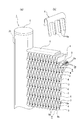
この発明に係る熱交換チューブ3を用いたコルゲートフィン式熱交換器1は、図1に示すように、それぞれアルミニウム(アルミニウム合金を含む)製の左右に対峙する一対のヘッダーパイプ2a,2bと、これらヘッダーパイプ2a,2b間に互いに平行に水平方向に架設(連結)される複数のこの発明に係る扁平状の熱交換チューブ3及び隣接する熱交換チューブ3間に介在されるコルゲートフィン4をろう付けしてなる。なお、熱交換チューブ3は、アルミニウム製押出形材にて形成されている。
この発明に係る熱交換チューブ3を用いたコルゲートフィン式熱交換器1は、図1に示すように、それぞれアルミニウム(アルミニウム合金を含む)製の左右に対峙する一対のヘッダーパイプ2a,2bと、これらヘッダーパイプ2a,2b間に互いに平行に水平方向に架設(連結)される複数のこの発明に係る扁平状の熱交換チューブ3及び隣接する熱交換チューブ3間に介在されるコルゲートフィン4をろう付けしてなる。なお、熱交換チューブ3は、アルミニウム製押出形材にて形成されている。
この場合、上下端のコルゲートフィン4の上部外方側及び下部外方側には、それぞれアルミニウム製のサイドプレート5がろう付けされている。また、ヘッダーパイプ2a,2bの上下開口端にはアルミニウム製のエンドキャップ6がろう付けされている。
上記のように構成される熱交換器1において、コルゲートフィン4は、薄板を所定の高さになるように山-谷折りを交互に繰り返して成形されており、熱交換器正面からの視点では、V字形状の連続として見ることができる。なお、コルゲートフィン4の形状は必ずしもV字形状の連続ではなく、U字形状の連続であってもよい。
なお、コルゲートフィン4の幅方向に互いに並行に設けられた複数の縦スリットを切り起こして形成されたフィンルーバ4a(図2(b)参照)を設けることにより、熱交換能力の向上が図れる、すなわち、空気の通路に所定角度に成形された所定数のルーバーを設けることで、乱流効果等により熱伝達性能の向上が図れる。
上記のように構成される熱交換器1において、図7に示すように、熱交換チューブ3は、複数の熱媒体の流通路3aを有する扁平状のチューブ本体3bと、チューブ本体3bの幅方向の両端部に延設される一対の鍔部7a,7bとを具備し、後述するこの発明に係る製造方法によって、両鍔部7a,7bにそれぞれ適宜ピッチをおいて切込みを介して傾斜状に切り起こされる複数の切起し片8a,8bが列設されている。両切起し片8a,8bは傾斜角θが同一であって、傾斜方向がチューブ本体3bの幅方向の両端で非対称に形成されている(図1ないし図4参照)。
この場合、切起し片8a,8bの上端部及び下端部は、それぞれチューブ本体3bの上面及び下面に位置し、配置される切起し片8a,8bの数は、コルゲートフィン4の山数以上に形成されている。このように形成することにより、隣接する各切起し片8a,8b間に、コルゲートフィン4間に保水される水を誘引する流水路9が形成される。
また、熱交換チューブ3の鍔部7a,7bの長手方向の両端部には、端部切欠き3cが形成されている(図4(a),(b)参照)。鍔部7a,7bの長手方向の両端部に端部切欠き3cを設けることにより、熱交換器の組付け(組立)時、ヘッダーパイプ2a,2bへ熱交換チューブ3を挿入する際に、挿入部分に鍔部7a,7bが無い方が組付け(組立)を容易にすることができる。
この発明に係る熱交換チューブ3とコルゲートフィン4を用いた排水メカニズムとしては、V字形状(谷折り)フィン表面に凝縮した凝縮水(結露水)は、下段への水路がないため、コルゲートフィン4の幅方向に互いに並行に設けられた複数の縦スリットを切り起こして形成されたフィンルーバ4a(図2(b)参照)を介して隣の逆V字形状(山折り)部に移動し、逆V字形状部に集まった凝縮水は、下方の開口部から、熱交換チューブ3に形成された流水路9を介して、下方側のコルゲートフィン4に流れ込むといったメカニズムをスムーズに繰り返すことにより、排水が促進される構造である。
この排水メカニズムにおいて、熱交換チューブ3に形成される流水路9の望ましい配置としては、その両脇すなわち熱交換チューブ3の長手方向の両側に位置するコルゲートフィン4を結ぶことである。このため、切起し片8a,8bの幅は熱交換チューブ3の厚さにより制約を受ける。また、切起し片8a,8bの幅Lは、コルゲートフィンの山頂点と谷頂点間のピッチPの2倍以下であることが好ましい。
上記のように形成される熱交換チューブ3によれば、熱媒体の流通路3aを有する扁平状のチューブ本体3bの幅方向の両端部に延設される一対の鍔部7a,7bに列設される両傾斜状切起し片8a,8bの傾斜角θが同一であって、傾斜方向がチューブ本体3bの幅方向の両端で非対称に形成されているので、幅方向の両端部に傾斜状切起し片8a,8bを有する熱交換チューブ3の長手方向、長手方向と直交する幅方向及び高さ(厚さ)の方向性に自由度をもたせることができる。したがって、切起し片8a,8bの傾斜の方向性に注意を払うことなく、熱交換器1の組付けを行うことができる。
また、切起し片8a,8bの上端部及び下端部は、それぞれチューブ本体3bの上面及び下面に位置し、配置される切起し片8a,8bの数は、コルゲートフィン4の山数以上に形成することにより、コルゲートフィン4の表面に凝縮し、水滴となった凝縮水(結露水)が、熱交換チューブ3の上下側に隣接するコルゲートフィン4間に保水された状態で、切起し片8a,8bの端部が保水に接触することで、流れ落ちる起点となり、水を誘引して下方側のコルゲートフィン4へ排出することができる。
また、チューブ本体3bと鍔部7a,7bはアルミニウム製の押出形材にて形成することにより、熱交換チューブ3自体の軽量化及びリサイクル性の向上が図れると共に、熱交換器の軽量化が図れる。
<熱交換チューブの製造方法>
次に、この発明に係る熱交換チューブ3の製造方法について、図5ないし図9を参照して説明する。この発明に係る熱交換チューブ3の製造方法は、以下のステップにより行われる。
次に、この発明に係る熱交換チューブ3の製造方法について、図5ないし図9を参照して説明する。この発明に係る熱交換チューブ3の製造方法は、以下のステップにより行われる。
(ステップS-1)図7に示すように、チューブ本体3b及び該チューブ本体3bの幅方向の両端部に延設される鍔部7a,7bを備えた鍔付き熱交換チューブ3Aを押出加工にて成形する(押出成形工程)。
(ステップS-2)押出成形された鍔付き熱交換チューブ3Aの幅方向の曲がりを矯正した後、図9(a)に示すように、鍔部7a,7bの長手方向に沿う所定幅Wに切欠きを施して、鍔付き熱交換チューブ3Aの長手方向に所定間隔をおいて端部切欠き3cを形成する(端部切欠き工程)。
(ステップS-3)端部切欠き工程の後、図9(b)に示すように、鍔付き熱交換チューブ3Aを後述する切起し加工装置10に挿入し、両側の鍔部7a,7bに所定の間隔で切込み及び切起し加工を行う(切起し片成形工程)。
切起し加工装置10は、図5及び図6に示すように、それぞれ上下面より互いに噛み合う刃部11a,11b;11c,11dを傾斜状に偏心させた一対の上下部ギア付きロール12a,12b;12c,12dを左右に2組(二対)具備している。この場合、切起し片8aを成形する一方の上下部ギア付きロール12a,12bは、図6Aに示すように、上部ギア付きロール12aの刃部11aは、鍔付き熱交換チューブ3Aの挿入側に対向する刃正面13aが鍔付き熱交換チューブ3Aの挿入側に対向して前傾し、刃背面14aの傾斜角が傾斜切起し片8aの傾斜角θと同じ角度に形成されている。一方、下部ギア付きロール12bの刃部11bは、上部ギア付きロール12aの刃部11aとは逆に鍔付き熱交換チューブ3Aの挿入側に対向する刃正面13bが傾斜切起し片8aの傾斜角θと同じ角度に形成され、下部ギア付きロール12bの刃部11bの刃背面14bが鍔付き熱交換チューブ3Aの挿入方向に沿う方向に傾斜している。
また、切起し片8bを成形する他方の上下部ギア付きロール12c,12dは、図6Bに示すように、上部ギア付きロール12cの刃部11cは、鍔付き熱交換チューブ3Aの挿入側に対向する刃正面13cが傾斜切起し片8bの傾斜角θと同じ角度に形成され、刃背面14cが鍔付き熱交換チューブ3aの挿入方向に沿って傾斜されている。一方、下部ギア付きロール12dの刃部11dは、上部ギア付きロール12cの刃部11cとは逆に鍔付き熱交換チューブ3Aの挿入側に対向する刃正面13dが鍔付き熱交換チューブ3Aの挿入側に対向して前傾し、下部ギア付きロール12dの刃部11dの刃背面14dの傾斜角が傾斜切起し片8bの傾斜角θと同じ角度に形成されている。
なお、上下部ギア付きロール12a~12dは、これら上下部ギア付きロール12a~12dを支持する回転軸15がボールベアリング16によって回転自在に支持されている。
この場合、切起し加工装置10の刃部11a~11dは、外径が50~100mm程度であれば、比較的容易に切断ラインに導入することが可能で刃先寿命の観点から表面には、刃先の摩耗を防止するために、窒化処理もしくは硬度を高める目的の表面処理を施していることが好ましい。
上記のように構成される上下部ギア付きロール12a,12b間に鍔付き熱交換チューブ3Aを通過する際に互いに反対方向に回動することで、まず、上下部ギア付きロール12a,12bの刃部11a,11bの刃先によって鍔部7aに切込みが施され、次いで下部ギア付きロール12bの刃部11bの刃正面13bで切込み部を切り起こしながら、下部ギア付きロール12bの刃部11bの刃正面13bと上部ギア付きロール12aの刃部11aの刃背面14aとが協同して切起し加工を行う(図6A(b)参照)。
また、上下部ギア付きロール12c,12d間に鍔付き熱交換チューブ3Aを通過する際に互いに反対方向に回動することで、まず、上下部ギア付きロール12c,12dの刃部11c,11dの刃先によって鍔部7bに切込みが施され、次いで上部ギア付きロール12cの刃部11cの刃背面14cで切込み部を切り起こしながら、上部ギア付きロール12cの刃部11cの刃正面13cと下部ギア付きロール12dの刃部11dの刃背面14dとが協同して切起し加工を行う(図6B(b)参照)。
上記のようにして、傾斜角θが同一であって、傾斜方向がチューブ本体3bの幅方向の両端で非対称の切起し片8a,8bが加工される。この場合、加工上の難易度を加味すると、極端に切起し片8a,8bの上下方向の幅(長さ)が短いと加工が困難となるため、切起し片8a,8bの幅(長さ)は2mm以上が好ましい。
なお、切起し片8a,8bの厚さについては、剪断加工性の観点から、0.2mm~0.8mmが好ましい。切起し片の厚さが0.2mmより薄いと、加工刃具の適正クリアランスが微小となるため剪断加工が難しくなり、また、切起し片8a,8bの厚さが0.8mmより厚くなると、大きな剪断力を必要とし、加工刃具の強度及び加工方法が限定されてしまう場合があるからである。
また、鍔部7a,7bの突出長さについては、押出加工性、熱交換器の組立時等の外力による変形、取り扱いの容易性を考慮すると、1~5mm程度がよく、より好ましくは1~3mm程度がよい。
また、扁平状チューブ本体3bの形状については必要となる熱交換性能に応じて決められるものであるが、厚み(T)が1~3mm程度、幅が10~25mm程度が空調用熱交換器用として一般的な形状となる。
上記のようにして、切起し加工装置10によって鍔付き熱交換チューブ3Aの両鍔部7a,7bに切起し片8a,8bを形成した後、図9(c)に示すように、鍔付き熱交換チューブ3Aにおける端部切欠き3cの中間部に分断切込み3dを施し(ステップS-4)、その後、図9(d)に示すように、分断切込み3dによって分断して、鍔付き熱交チューブ3Aの長手方向における所定寸法の熱交換チューブ3を作製する(ステップS-5;チューブ分断工程)。
上記のようにして作製された熱交換チューブ3は、両鍔部7a,7bに列設される両傾斜状切起し片8a,8bの傾斜角θが同一であって、傾斜方向がチューブ本体3bの幅方向の両端で非対称に形成される。したがって、熱交換チューブ3の長手方向、長手方向と直交する幅方向及び高さ(厚さ)の方向性に自由度をもたせることができるため、切起し片8a,8bの傾斜の方向性に注意を払うことなく、互いに平行に配置されるコルゲートフィン4間に交互に配置すると共に、一対のヘッダーパイプ2a,2b間に組付けて熱交換器コアを組み立てる(ステップS-6)この状態で、炉(図示せず)内に搬入し、所定温度に加熱してろう付けする(ステップS-7)。
上記実施形態の熱交換チューブの製造方法によれば、チューブ本体3b及び該チューブ本体3bの幅方向の両端部に延設される鍔部7a,7bを備えた鍔付き熱交換チューブ3Aを押出加工にて成形し、押出成形後、鍔付き熱交換チューブ3Aの長手方向の前後を所定の長さに切断するチューブ分断工程の前に、両端部の鍔部7a,7bを、それぞれ上下面より互いに噛み合う刃部11a~11dを傾斜状に偏心させた一対のギア付きロール12a,12b又は12c,12d間を通過させて、所定の間隔で鍔部7a,7bに切込み及び切起し加工を行って切起し片8a,8bを成形するので、プレス加工装置のような大掛かりな装置は不要で、押出加工後の切断ラインに導入することができる。また、切断位置を変えることによって熱交換チューブ3の長さの変更を容易にすることができる。
この場合、鍔付き熱交換チューブ3Aの幅方向の両端部に延設される両鍔部7a,7bを二対のギア付きロール12a,12b;12c,12d間を通過させて切込み及び切起し加工を同時に行うことにより、切込み及び切り起こし加工時の熱交換チューブ曲がり発生を抑制できる。
また、ギア付きロール12a,12b;12c,12dは、鍔付き熱交換チューブ3Aが通過する際に互いに反対方向に回動することで、切込み及び切起し加工するので、押出加工及び切断加工を具備する製造ラインに組み込むことが容易で、駆動源を用いずに、傾斜状切起し片の加工を容易にすることができる。
また、両鍔部7a,7bの長手方向に沿う所定幅の端部切欠き3cを長手方向に所定間隔をおいて形成する端部切欠き工程を行い、前端部サイジング工程及び後端部分断工程において、端部切欠き3cの中間部を切断することにより、鍔部7a,7bに切起し片8a,8bを成形する過程で、端部切欠き3cを形成することができる。したがって、端部切欠き加工と切起し片成形加工を連続して行うことができるため、生産性の向上を図ることができる。
なお、上記実施形態では、この発明に係る熱交換チューブ3を用いた熱交換器1を蒸発器に適用した場合について説明したが、この発明は、蒸発器以外のパラレルフロー型コルゲートフィン式熱交換器においても、熱交換チューブ3を水平配置して適用することができる。
1 熱交換器
2a,2b ヘッダーパイプ
3 熱交換チューブ
3A 鍔付き熱交換チューブ
3a 熱媒体流通路
3b 扁平状チューブ本体
3c 端部切欠き
4 コルゲートフィン
7a,7b 鍔部
8a,8b 切起し片
9 流水路
10 切起し加工装置
11a,11b,11c,11d 刃部
12a,12c 上部ギア付きロール
12b,12d 下部ギア付きロール
13a,13b,13c,13d 刃正面
14a,14b,14c,14d 刃背面
15 回転軸
16 ボールベアリング
P コルゲートフィンのピッチ
θ 切起し片の傾斜角度
2a,2b ヘッダーパイプ
3 熱交換チューブ
3A 鍔付き熱交換チューブ
3a 熱媒体流通路
3b 扁平状チューブ本体
3c 端部切欠き
4 コルゲートフィン
7a,7b 鍔部
8a,8b 切起し片
9 流水路
10 切起し加工装置
11a,11b,11c,11d 刃部
12a,12c 上部ギア付きロール
12b,12d 下部ギア付きロール
13a,13b,13c,13d 刃正面
14a,14b,14c,14d 刃背面
15 回転軸
16 ボールベアリング
P コルゲートフィンのピッチ
θ 切起し片の傾斜角度
Claims (7)
- 対峙する一対のヘッダーパイプ間に、互いに平行な複数の扁平状熱交換チューブを水平方向に配置し、山-谷折りを交互に繰り返して成形されたコルゲートフィンを上記熱交換チューブ間に接合してなる熱交換器における熱交換チューブであって、
上記熱交換チューブは、熱媒体の流通路を有する扁平状のチューブ本体と、該チューブ本体の幅方向の両端部に延設される一対の鍔部と、両鍔部をチューブ本体の長手方向に沿って適宜間隔をおいて列設される傾斜状に切り起こした切起し片と、を具備し、
上記両切起し片の傾斜角が同一であって、傾斜方向が上記チューブ本体の幅方向の両端で非対称に形成されている、ことを特徴とする熱交換器における熱交換チューブ。 - 請求項1に記載の熱交換器における熱交換チューブにおいて、
上記切起し片の上端部及び下端部は、それぞれ上記チューブ本体の上面及び下面に位置し、かつ、配置される切起し片の数は、組み合わされるコルゲートフィンの山数以上である、ことを特徴とする熱交換器における熱交換チューブ。 - 請求項1又は2に記載の熱交換器における熱交換チューブにおいて、
上記熱交換チューブの長手方向の両端部における上記両鍔部に端部切欠きを形成してなる、ことを特徴とする熱交換器における熱交換チューブ。 - 請求項1ないし3のいずれかに記載の熱交換器における熱交換チューブにおいて、
上記チューブ本体と鍔部はアルミニウム製の押出形材にて形成されている、ことを特徴とする熱交換器における熱交換チューブ。 - 請求項1ないし4のいずれかに記載の熱交換器における熱交換チューブの製造方法であって、
上記チューブ本体及び該チューブ本体の幅方向の両端部に延設される上記鍔部を備えた鍔付き熱交換チューブを押出加工にて成形する押出成形工程と、
上記押出成形工程の後に、上記両端部の鍔部を、それぞれ上下面より互いに噛み合う刃部を傾斜状に偏心させた一対のギア付きロール間を通過させて、所定の間隔で上記鍔部に切込み及び切起し加工を行う切起し片成形工程と、
上記切起し片成形工程の後、上記鍔付き熱交換チューブの長手方向の前後を所定の長さに切断するチューブ分断工程と、を具備することを特徴とする熱交換器における熱交換チューブの製造方法。 - 請求項5に記載の熱交換器における熱交換チューブの製造方法において、
上記鍔付き熱交換チューブの幅方向の両端部に延設される両鍔部を二対の上記ギア付きロール間を通過させて切込み及び切起し加工を同時に行う、ことを特徴とする熱交換器における熱交換チューブの製造方法。 - 請求項5又は6に記載の熱交換器における熱交換チューブの製造方法において、
上記ギア付きロールは、上記鍔付き熱交換チューブが通過する際に互いに反対方向に回動することで、切込み及び切起し加工する、ことを特徴とする熱交換器における熱交換チューブの製造方法。
Applications Claiming Priority (2)
| Application Number | Priority Date | Filing Date | Title |
|---|---|---|---|
| JP2012281953A JP5946217B2 (ja) | 2012-12-26 | 2012-12-26 | 熱交換器における熱交換チューブ及び熱交換チューブの製造方法 |
| JP2012-281953 | 2012-12-26 |
Publications (1)
| Publication Number | Publication Date |
|---|---|
| WO2014103268A1 true WO2014103268A1 (ja) | 2014-07-03 |
Family
ID=51020388
Family Applications (1)
| Application Number | Title | Priority Date | Filing Date |
|---|---|---|---|
| PCT/JP2013/007498 Ceased WO2014103268A1 (ja) | 2012-12-26 | 2013-12-20 | 熱交換器における熱交換チューブ及び熱交換チューブの製造方法 |
Country Status (2)
| Country | Link |
|---|---|
| JP (1) | JP5946217B2 (ja) |
| WO (1) | WO2014103268A1 (ja) |
Cited By (4)
| Publication number | Priority date | Publication date | Assignee | Title |
|---|---|---|---|---|
| JP2016161158A (ja) * | 2015-02-27 | 2016-09-05 | 昭和電工株式会社 | 液冷式冷却装置 |
| WO2018029203A1 (de) * | 2016-08-08 | 2018-02-15 | Bundy Refrigeration International Holding B.V. | Wärmetauscher mit mikrokanal-struktur oder flügelrohr-struktur |
| WO2021013964A1 (de) * | 2019-07-23 | 2021-01-28 | Bundy Refrigeration Gmbh | Extrudierter flügelrohrabschnitt, flügelrohr mit extrudiertem flügelrohrabschnitt und wärmetauscher mit flügelrohr sowie herstellungsverfahren eines flügelrohrabschnitts |
| EP4273490A4 (en) * | 2020-12-30 | 2024-11-13 | Danfoss A/S | HEAT EXCHANGER |
Families Citing this family (2)
| Publication number | Priority date | Publication date | Assignee | Title |
|---|---|---|---|---|
| JP6330577B2 (ja) * | 2014-08-22 | 2018-05-30 | 日本軽金属株式会社 | フィン・アンド・チューブ型熱交換器 |
| WO2017072945A1 (ja) * | 2015-10-30 | 2017-05-04 | 三菱電機株式会社 | 熱交換器及び空気調和機 |
Citations (7)
| Publication number | Priority date | Publication date | Assignee | Title |
|---|---|---|---|---|
| US2347957A (en) * | 1939-06-17 | 1944-05-02 | William E Mccullough | Heat exchange unit |
| JPS498625B1 (ja) * | 1969-07-14 | 1974-02-27 | ||
| JPS5035747A (ja) * | 1973-08-03 | 1975-04-04 | ||
| JPS5332445A (en) * | 1976-09-06 | 1978-03-27 | Sumitomo Light Metal Ind | Method of forming fin |
| JP2004279023A (ja) * | 2003-03-13 | 2004-10-07 | Lg Electronics Inc | 熱交換器及びその製造方法 |
| WO2012172716A1 (ja) * | 2011-06-16 | 2012-12-20 | 日本軽金属株式会社 | コルゲートフィン式熱交換器の排水構造 |
| JP2012251719A (ja) * | 2011-06-03 | 2012-12-20 | Nippon Light Metal Co Ltd | コルゲートフィン式熱交換器の排水構造 |
Family Cites Families (3)
| Publication number | Priority date | Publication date | Assignee | Title |
|---|---|---|---|---|
| JP5250924B2 (ja) * | 2001-07-16 | 2013-07-31 | 株式会社デンソー | 排気熱交換器 |
| JP5005400B2 (ja) * | 2007-03-26 | 2012-08-22 | 株式会社日本クライメイトシステムズ | 熱交換器 |
| JP5550106B2 (ja) * | 2009-03-17 | 2014-07-16 | 日本軽金属株式会社 | コルゲートフィン式熱交換器の排水構造 |
-
2012
- 2012-12-26 JP JP2012281953A patent/JP5946217B2/ja active Active
-
2013
- 2013-12-20 WO PCT/JP2013/007498 patent/WO2014103268A1/ja not_active Ceased
Patent Citations (7)
| Publication number | Priority date | Publication date | Assignee | Title |
|---|---|---|---|---|
| US2347957A (en) * | 1939-06-17 | 1944-05-02 | William E Mccullough | Heat exchange unit |
| JPS498625B1 (ja) * | 1969-07-14 | 1974-02-27 | ||
| JPS5035747A (ja) * | 1973-08-03 | 1975-04-04 | ||
| JPS5332445A (en) * | 1976-09-06 | 1978-03-27 | Sumitomo Light Metal Ind | Method of forming fin |
| JP2004279023A (ja) * | 2003-03-13 | 2004-10-07 | Lg Electronics Inc | 熱交換器及びその製造方法 |
| JP2012251719A (ja) * | 2011-06-03 | 2012-12-20 | Nippon Light Metal Co Ltd | コルゲートフィン式熱交換器の排水構造 |
| WO2012172716A1 (ja) * | 2011-06-16 | 2012-12-20 | 日本軽金属株式会社 | コルゲートフィン式熱交換器の排水構造 |
Cited By (4)
| Publication number | Priority date | Publication date | Assignee | Title |
|---|---|---|---|---|
| JP2016161158A (ja) * | 2015-02-27 | 2016-09-05 | 昭和電工株式会社 | 液冷式冷却装置 |
| WO2018029203A1 (de) * | 2016-08-08 | 2018-02-15 | Bundy Refrigeration International Holding B.V. | Wärmetauscher mit mikrokanal-struktur oder flügelrohr-struktur |
| WO2021013964A1 (de) * | 2019-07-23 | 2021-01-28 | Bundy Refrigeration Gmbh | Extrudierter flügelrohrabschnitt, flügelrohr mit extrudiertem flügelrohrabschnitt und wärmetauscher mit flügelrohr sowie herstellungsverfahren eines flügelrohrabschnitts |
| EP4273490A4 (en) * | 2020-12-30 | 2024-11-13 | Danfoss A/S | HEAT EXCHANGER |
Also Published As
| Publication number | Publication date |
|---|---|
| JP2014126240A (ja) | 2014-07-07 |
| JP5946217B2 (ja) | 2016-07-05 |
Similar Documents
| Publication | Publication Date | Title |
|---|---|---|
| JP5946217B2 (ja) | 熱交換器における熱交換チューブ及び熱交換チューブの製造方法 | |
| JP4300508B2 (ja) | 熱交換器用プレートフィンおよび熱交換器コア | |
| EP2869016B1 (en) | Heat exchanger, method for manufacturing heat exchanger, and air conditioner | |
| JP5678392B2 (ja) | コルゲートフィン式熱交換器の排水構造 | |
| EP2857785B1 (en) | Heat exchanger and air conditioner | |
| JP5417718B2 (ja) | 熱交換器 | |
| JP2010169289A (ja) | 屈曲状熱交換器及びその製造方法 | |
| CN110741218A (zh) | 热交换器及波纹状翅片 | |
| CN106918261B (zh) | 一种翅片及热交换器 | |
| JP5550106B2 (ja) | コルゲートフィン式熱交換器の排水構造 | |
| CN100398917C (zh) | 带翅片热交换器及其制造方法 | |
| JP3947158B2 (ja) | 熱交換器 | |
| WO2013161193A1 (ja) | フィンチューブ熱交換器及びそれを備えた冷凍サイクル装置 | |
| JP5042927B2 (ja) | 熱交換器 | |
| JP3903888B2 (ja) | 熱交換器 | |
| CN204313688U (zh) | 翅片和具有该翅片的换热器 | |
| JP3979118B2 (ja) | 熱交換器、熱交換器の製造方法及び空気調和機 | |
| JP7522956B2 (ja) | 熱交換器およびそれを用いた空気調和機 | |
| JP2004263881A (ja) | 伝熱フィン、熱交換器、カーエアコン用エバポレータ及びコンデンサ | |
| JP2007292453A (ja) | 熱交換器用ルーバ付きフィン | |
| JP7788862B2 (ja) | 熱交換器の製造方法および空気調和機の製造方法 | |
| CN103791661A (zh) | 翅片管热交换器 | |
| JPH0545474U (ja) | 熱交換器 | |
| JP2005121348A (ja) | 熱交換器および伝熱部材 | |
| JP2019045033A (ja) | コルゲートフィン式熱交換器 |
Legal Events
| Date | Code | Title | Description |
|---|---|---|---|
| 121 | Ep: the epo has been informed by wipo that ep was designated in this application |
Ref document number: 13867756 Country of ref document: EP Kind code of ref document: A1 |
|
| NENP | Non-entry into the national phase |
Ref country code: DE |
|
| 122 | Ep: pct application non-entry in european phase |
Ref document number: 13867756 Country of ref document: EP Kind code of ref document: A1 |