WO2014103268A1 - Tube d'échange de chaleur dans un échangeur thermique et procédé de production d'un tube d'échange de chaleur - Google Patents
Tube d'échange de chaleur dans un échangeur thermique et procédé de production d'un tube d'échange de chaleur Download PDFInfo
- Publication number
- WO2014103268A1 WO2014103268A1 PCT/JP2013/007498 JP2013007498W WO2014103268A1 WO 2014103268 A1 WO2014103268 A1 WO 2014103268A1 JP 2013007498 W JP2013007498 W JP 2013007498W WO 2014103268 A1 WO2014103268 A1 WO 2014103268A1
- Authority
- WO
- WIPO (PCT)
- Prior art keywords
- heat exchange
- exchange tube
- tube
- cut
- heat exchanger
- Prior art date
- Legal status (The legal status is an assumption and is not a legal conclusion. Google has not performed a legal analysis and makes no representation as to the accuracy of the status listed.)
- Ceased
Links
Images



Classifications
-
- F—MECHANICAL ENGINEERING; LIGHTING; HEATING; WEAPONS; BLASTING
- F28—HEAT EXCHANGE IN GENERAL
- F28F—DETAILS OF HEAT-EXCHANGE AND HEAT-TRANSFER APPARATUS, OF GENERAL APPLICATION
- F28F1/00—Tubular elements; Assemblies of tubular elements
- F28F1/10—Tubular elements and assemblies thereof with means for increasing heat-transfer area, e.g. with fins, with projections, with recesses
- F28F1/12—Tubular elements and assemblies thereof with means for increasing heat-transfer area, e.g. with fins, with projections, with recesses the means being only outside the tubular element
- F28F1/126—Tubular elements and assemblies thereof with means for increasing heat-transfer area, e.g. with fins, with projections, with recesses the means being only outside the tubular element consisting of zig-zag shaped fins
-
- B—PERFORMING OPERATIONS; TRANSPORTING
- B21—MECHANICAL METAL-WORKING WITHOUT ESSENTIALLY REMOVING MATERIAL; PUNCHING METAL
- B21C—MANUFACTURE OF METAL SHEETS, WIRE, RODS, TUBES, PROFILES OR LIKE SEMI-MANUFACTURED PRODUCTS OTHERWISE THAN BY ROLLING; AUXILIARY OPERATIONS USED IN CONNECTION WITH METAL-WORKING WITHOUT ESSENTIALLY REMOVING MATERIAL
- B21C37/00—Manufacture of metal sheets, rods, wire, tubes, profiles or like semi-manufactured products, not otherwise provided for; Manufacture of tubes of special shape
- B21C37/06—Manufacture of metal sheets, rods, wire, tubes, profiles or like semi-manufactured products, not otherwise provided for; Manufacture of tubes of special shape of tubes or metal hoses; Combined procedures for making tubes, e.g. for making multi-wall tubes
- B21C37/15—Making tubes of special shape; Making tube fittings
- B21C37/151—Making tubes with multiple passages
-
- B—PERFORMING OPERATIONS; TRANSPORTING
- B21—MECHANICAL METAL-WORKING WITHOUT ESSENTIALLY REMOVING MATERIAL; PUNCHING METAL
- B21C—MANUFACTURE OF METAL SHEETS, WIRE, RODS, TUBES, PROFILES OR LIKE SEMI-MANUFACTURED PRODUCTS OTHERWISE THAN BY ROLLING; AUXILIARY OPERATIONS USED IN CONNECTION WITH METAL-WORKING WITHOUT ESSENTIALLY REMOVING MATERIAL
- B21C37/00—Manufacture of metal sheets, rods, wire, tubes, profiles or like semi-manufactured products, not otherwise provided for; Manufacture of tubes of special shape
- B21C37/06—Manufacture of metal sheets, rods, wire, tubes, profiles or like semi-manufactured products, not otherwise provided for; Manufacture of tubes of special shape of tubes or metal hoses; Combined procedures for making tubes, e.g. for making multi-wall tubes
- B21C37/15—Making tubes of special shape; Making tube fittings
- B21C37/20—Making helical or similar guides in or on tubes without removing material, e.g. by drawing same over mandrels, by pushing same through dies ; Making tubes with angled walls, ribbed tubes or tubes with decorated walls
-
- F—MECHANICAL ENGINEERING; LIGHTING; HEATING; WEAPONS; BLASTING
- F28—HEAT EXCHANGE IN GENERAL
- F28D—HEAT-EXCHANGE APPARATUS, NOT PROVIDED FOR IN ANOTHER SUBCLASS, IN WHICH THE HEAT-EXCHANGE MEDIA DO NOT COME INTO DIRECT CONTACT
- F28D1/00—Heat-exchange apparatus having stationary conduit assemblies for one heat-exchange medium only, the media being in contact with different sides of the conduit wall, in which the other heat-exchange medium is a large body of fluid, e.g. domestic or motor car radiators
- F28D1/02—Heat-exchange apparatus having stationary conduit assemblies for one heat-exchange medium only, the media being in contact with different sides of the conduit wall, in which the other heat-exchange medium is a large body of fluid, e.g. domestic or motor car radiators with heat-exchange conduits immersed in the body of fluid
- F28D1/04—Heat-exchange apparatus having stationary conduit assemblies for one heat-exchange medium only, the media being in contact with different sides of the conduit wall, in which the other heat-exchange medium is a large body of fluid, e.g. domestic or motor car radiators with heat-exchange conduits immersed in the body of fluid with tubular conduits
- F28D1/053—Heat-exchange apparatus having stationary conduit assemblies for one heat-exchange medium only, the media being in contact with different sides of the conduit wall, in which the other heat-exchange medium is a large body of fluid, e.g. domestic or motor car radiators with heat-exchange conduits immersed in the body of fluid with tubular conduits the conduits being straight
- F28D1/0535—Heat-exchange apparatus having stationary conduit assemblies for one heat-exchange medium only, the media being in contact with different sides of the conduit wall, in which the other heat-exchange medium is a large body of fluid, e.g. domestic or motor car radiators with heat-exchange conduits immersed in the body of fluid with tubular conduits the conduits being straight the conduits having a non-circular cross-section
- F28D1/05366—Assemblies of conduits connected to common headers, e.g. core type radiators
- F28D1/05383—Assemblies of conduits connected to common headers, e.g. core type radiators with multiple rows of conduits or with multi-channel conduits
-
- F—MECHANICAL ENGINEERING; LIGHTING; HEATING; WEAPONS; BLASTING
- F28—HEAT EXCHANGE IN GENERAL
- F28F—DETAILS OF HEAT-EXCHANGE AND HEAT-TRANSFER APPARATUS, OF GENERAL APPLICATION
- F28F1/00—Tubular elements; Assemblies of tubular elements
- F28F1/02—Tubular elements of cross-section which is non-circular
- F28F1/022—Tubular elements of cross-section which is non-circular with multiple channels
-
- F—MECHANICAL ENGINEERING; LIGHTING; HEATING; WEAPONS; BLASTING
- F28—HEAT EXCHANGE IN GENERAL
- F28F—DETAILS OF HEAT-EXCHANGE AND HEAT-TRANSFER APPARATUS, OF GENERAL APPLICATION
- F28F1/00—Tubular elements; Assemblies of tubular elements
- F28F1/10—Tubular elements and assemblies thereof with means for increasing heat-transfer area, e.g. with fins, with projections, with recesses
- F28F1/12—Tubular elements and assemblies thereof with means for increasing heat-transfer area, e.g. with fins, with projections, with recesses the means being only outside the tubular element
- F28F1/24—Tubular elements and assemblies thereof with means for increasing heat-transfer area, e.g. with fins, with projections, with recesses the means being only outside the tubular element and extending transversely
- F28F1/26—Tubular elements and assemblies thereof with means for increasing heat-transfer area, e.g. with fins, with projections, with recesses the means being only outside the tubular element and extending transversely the means being integral with the element
-
- F—MECHANICAL ENGINEERING; LIGHTING; HEATING; WEAPONS; BLASTING
- F28—HEAT EXCHANGE IN GENERAL
- F28F—DETAILS OF HEAT-EXCHANGE AND HEAT-TRANSFER APPARATUS, OF GENERAL APPLICATION
- F28F17/00—Removing ice or water from heat-exchange apparatus
- F28F17/005—Means for draining condensates from heat exchangers, e.g. from evaporators
-
- F—MECHANICAL ENGINEERING; LIGHTING; HEATING; WEAPONS; BLASTING
- F25—REFRIGERATION OR COOLING; COMBINED HEATING AND REFRIGERATION SYSTEMS; HEAT PUMP SYSTEMS; MANUFACTURE OR STORAGE OF ICE; LIQUEFACTION SOLIDIFICATION OF GASES
- F25B—REFRIGERATION MACHINES, PLANTS OR SYSTEMS; COMBINED HEATING AND REFRIGERATION SYSTEMS; HEAT PUMP SYSTEMS
- F25B39/00—Evaporators; Condensers
-
- F—MECHANICAL ENGINEERING; LIGHTING; HEATING; WEAPONS; BLASTING
- F28—HEAT EXCHANGE IN GENERAL
- F28D—HEAT-EXCHANGE APPARATUS, NOT PROVIDED FOR IN ANOTHER SUBCLASS, IN WHICH THE HEAT-EXCHANGE MEDIA DO NOT COME INTO DIRECT CONTACT
- F28D21/00—Heat-exchange apparatus not covered by any of the groups F28D1/00 - F28D20/00
- F28D2021/0019—Other heat exchangers for particular applications; Heat exchange systems not otherwise provided for
- F28D2021/0068—Other heat exchangers for particular applications; Heat exchange systems not otherwise provided for for refrigerant cycles
- F28D2021/0071—Evaporators
-
- F—MECHANICAL ENGINEERING; LIGHTING; HEATING; WEAPONS; BLASTING
- F28—HEAT EXCHANGE IN GENERAL
- F28F—DETAILS OF HEAT-EXCHANGE AND HEAT-TRANSFER APPARATUS, OF GENERAL APPLICATION
- F28F2215/00—Fins
- F28F2215/08—Fins with openings, e.g. louvers
-
- F—MECHANICAL ENGINEERING; LIGHTING; HEATING; WEAPONS; BLASTING
- F28—HEAT EXCHANGE IN GENERAL
- F28F—DETAILS OF HEAT-EXCHANGE AND HEAT-TRANSFER APPARATUS, OF GENERAL APPLICATION
- F28F2255/00—Heat exchanger elements made of materials having special features or resulting from particular manufacturing processes
- F28F2255/16—Heat exchanger elements made of materials having special features or resulting from particular manufacturing processes extruded
Definitions
- the present invention relates to a heat exchange tube in a heat exchanger and a method for producing the heat exchange tube, and more specifically, heat in a parallel flow heat exchanger in which corrugated fins and flat heat exchange tubes are alternately arranged.
- the present invention relates to an exchange tube and a method for producing a heat exchange tube.
- corrugated fin-type heat exchangers are widely used in which a plurality of flat heat exchange tubes parallel to each other are horizontally arranged between a pair of opposing header pipes and corrugated fins are joined between the heat exchange tubes. in use.
- this type of corrugated fin heat exchanger is used as an evaporator, condensed water (condensed water) adheres to the surface, increasing the airflow resistance, and further, the water film adhering to the corrugated fin surface acts as a resistance to transfer heat. There is a problem that the heat exchange performance is lowered.
- the heat exchange tube is formed by inclining a flange extending at the end in the width direction of the heat exchange tube. Proposed a drainage structure provided with an appropriate pitch in the longitudinal direction (see, for example, Patent Document 1).
- the water channel that attracts water retained between the corrugated fins adjacent to the upper and lower sides of the heat exchange tube is formed by raising the collar portion in an inclined manner.
- the condensed water (condensation water) adhering to the surface of the heat exchanger can be drained.
- JP 2010-243147 A (Claims, FIGS. 1 to 3)
- the present invention has been made in view of the above circumstances, and provides a heat exchange tube having a drainage function that facilitates assembly of a heat exchanger and manufacture of the heat exchange tube that facilitates processing of the heat exchange tube It is an object to provide a method.
- the heat exchange tube of the present invention has a plurality of flat heat exchange tubes parallel to each other between a pair of opposing header pipes in a horizontal direction, and alternately repeats mountain-valley folding.
- the heat exchange tube includes a flat tube body having a heat medium passage and both ends of the tube body in the width direction.
- the upper and lower ends of the cut and raised pieces are positioned on the upper and lower surfaces of the tube body, respectively, and the number of cut and raised pieces to be arranged is corrugated fins. It is preferable that it is more than the number of peaks.
- end notches are formed in the both flanges at both ends in the longitudinal direction of the heat exchange tube (claim 3).
- the tube main body and the collar portion are formed of an extruded shape made of aluminum (claim 4).
- the manufacturing method of the heat exchange tube of this invention is a manufacturing method of the heat exchange tube in the heat exchanger in any one of Claim 1 thru
- both flanges extending at both end portions in the width direction of the flanged heat exchange tube are respectively passed between the pair of geared rolls to cut and raise.
- the geared roll rotates in opposite directions when the flanged heat exchange tube passes, thereby performing cutting and raising and cutting processes.
- the two inclined cut-and-raised pieces arranged in a pair of eaves extending at both ends in the width direction of the flat tube body having a heat medium flow passage are provided. Since the inclination angle is the same and the inclination direction is formed asymmetrically at both ends in the width direction of the tube body, the longitudinal direction and the longitudinal direction of the heat exchange tube having inclined cut and raised pieces at both ends in the width direction A degree of freedom can be given to the directionality of the width direction and height (thickness) orthogonal to the direction.
- the upper and lower ends of the cut and raised pieces are located on the upper and lower surfaces of the tube main body, respectively, and the number of cut and raised pieces to be arranged is equal to or greater than the number of corrugated fins combined.
- Condensed water condensation water
- Condensation water that condenses on the surface of the corrugated fins and remains as water droplets is retained between the corrugated fins adjacent to the upper and lower sides of the heat exchange tube, and the ends of the cut pieces come into contact with the retained water. By doing so, it becomes a starting point to flow down, and water can be attracted and discharged to the corrugated fin on the lower side.
- the heat exchange tube itself can be reduced in weight and recyclability, and the heat exchanger can be reduced in weight.
- a heat exchange tube with a hook provided with a tube body and a flange extending at both ends in the width direction of the tube body is formed by extrusion, After extrusion molding, after forming notches on both flanges at both ends in the longitudinal direction of the heat exchanger tube with a flange, the blades that engage with each other from the upper and lower surfaces of the flanges at both ends are eccentrically inclined.
- a large-scale device such as a press working device is unnecessary. It can be introduced into the cutting line after extrusion.
- the change of the length of a heat exchange tube can be made easy.
- both the flanges extending at both ends in the width direction of the flanged heat exchange tube are passed between two pairs of geared rolls, and the cutting and raising process are performed simultaneously, so that the cutting and raising are performed.
- the occurrence of bending of the heat exchange tube during processing can be suppressed.
- the geared roll is incorporated into a production line equipped with extrusion and cutting by turning and cutting up by rotating in opposite directions when the heat exchange tube with a flange passes. It is easy to process the inclined cut and raised pieces without using a drive source.
- the longitudinal direction of the heat exchange tube having inclined cut and raised pieces at both ends in the width direction, the width direction orthogonal to the longitudinal direction, and the directionality of height (thickness) are free. Therefore, it is possible to prevent erroneous assembly related to the direction of the heat exchange tube and facilitate assembly to the heat exchanger.
- a large-scale device such as a press processing device is unnecessary, and can be introduced into a cutting line after extrusion, and the change of the length of the heat exchange tube can be easily performed. Therefore, the productivity can be improved and the manufacturing cost can be reduced.
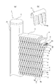
- a corrugated fin heat exchanger 1 using a heat exchange tube 3 according to the present invention includes a pair of header pipes 2 a and 2 b facing each other made of aluminum (including an aluminum alloy), The plurality of flat heat exchange tubes 3 according to the present invention that are installed (connected) in parallel with each other between the header pipes 2a and 2b and the corrugated fins 4 interposed between the adjacent heat exchange tubes 3 are brazed. It is attached.
- the heat exchange tube 3 is formed of an aluminum extruded shape.
- aluminum side plates 5 are brazed to the upper outer side and the lower outer side of the corrugated fins 4 at the upper and lower ends, respectively.
- An end cap 6 made of aluminum is brazed to the upper and lower opening ends of the header pipes 2a and 2b.
- the corrugated fins 4 are formed by alternately repeating a mountain-valley fold so that a thin plate has a predetermined height. From the viewpoint of the heat exchanger front, , Can be viewed as a continuous V-shape.
- the shape of the corrugated fin 4 is not necessarily a continuous V shape, but may be a continuous U shape.
- the heat exchange capability can be improved.
- heat transfer performance can be improved due to a turbulent flow effect or the like.
- the heat exchange tube 3 includes a flat tube main body 3b having a plurality of heat medium flow passages 3a, and a width direction of the tube main body 3b. And a pair of flanges 7a, 7b extending at both ends of the flange, and by the manufacturing method according to the present invention, which will be described later, the both flanges 7a, 7b are inclined at appropriate pitches through the notches.
- a plurality of cut and raised pieces 8a and 8b to be cut and raised are arranged in a line. Both the cut and raised pieces 8a and 8b have the same inclination angle ⁇ , and the inclination direction is formed asymmetrically at both ends in the width direction of the tube body 3b (see FIGS. 1 to 4).
- the upper and lower ends of the cut and raised pieces 8a and 8b are located on the upper and lower surfaces of the tube body 3b, respectively, and the number of the cut and raised pieces 8a and 8b arranged is the number of the corrugated fins 4 It is formed as described above.
- a flow channel 9 for attracting water retained between the corrugated fins 4 is formed between the adjacent raised and raised pieces 8a and 8b.
- end notches 3c are formed at both ends in the longitudinal direction of the flanges 7a and 7b of the heat exchange tube 3 (see FIGS. 4A and 4B).
- end notches 3c are formed at both longitudinal ends of the flanges 7a and 7b, when the heat exchanger tube 3 is inserted into the header pipes 2a and 2b when the heat exchanger is assembled (assembled), it is inserted. Assembling (assembling) can be facilitated if the portions do not have the flanges 7a and 7b.
- the condensed water (condensed water) condensed on the surface of the V-shaped (valley fold) fin has no water channel to the lower stage. 4 through a fin louver 4a (see FIG. 2 (b)) formed by cutting and raising a plurality of vertical slits provided in parallel to each other in the width direction of 4 and moving to the next inverted V-shaped (mountain fold) part, By repeating smoothly the mechanism that the condensed water collected in the inverted V-shaped part flows into the corrugated fin 4 on the lower side through the flowing water passage 9 formed in the heat exchange tube 3 from the lower opening, This structure promotes drainage.
- a desirable arrangement of the flow channel 9 formed in the heat exchange tube 3 is to tie corrugated fins 4 located on both sides thereof, that is, on both sides in the longitudinal direction of the heat exchange tube 3. For this reason, the width of the cut and raised pieces 8 a and 8 b is restricted by the thickness of the heat exchange tube 3. Further, the width L of the cut and raised pieces 8a and 8b is preferably not more than twice the pitch P between the peak and trough vertices of the corrugated fin.
- the flat tube body 3b having the heat medium flow passage 3a is arranged in a row on the pair of flange portions 7a and 7b extending at both ends in the width direction. Since the inclined angles ⁇ of the two inclined cut and raised pieces 8a and 8b are the same and the inclination direction is formed asymmetrically at both ends in the width direction of the tube main body 3b, it is inclined at both ends in the width direction.
- the heat exchange tube 3 having the cut and raised pieces 8a and 8b can have a degree of freedom in the direction of the longitudinal direction, the width direction orthogonal to the longitudinal direction, and the height (thickness). Therefore, the heat exchanger 1 can be assembled without paying attention to the directionality of the inclination of the cut and raised pieces 8a and 8b.
- the upper and lower ends of the cut and raised pieces 8a and 8b are positioned on the upper and lower surfaces of the tube body 3b, respectively, and the number of the raised and raised pieces 8a and 8b arranged is equal to or greater than the number of the corrugated fins 4.
- the condensed water condensed water
- the end portions of the strips 8a and 8b come into contact with the water retention, it becomes a starting point that flows down, and water can be attracted and discharged to the corrugated fin 4 on the lower side.
- the tube body 3b and the flanges 7a and 7b are formed of an aluminum extruded shape, so that the heat exchange tube 3 itself can be reduced in weight and recyclability, and the heat exchanger can be reduced in weight. .
- Step S-1 As shown in FIG. 7, a heat exchange tube 3A with a flange having a tube body 3b and flange portions 7a and 7b extending at both ends in the width direction of the tube body 3b is subjected to extrusion processing. To form (extrusion molding process).
- Step S-2 After correcting the bending in the width direction of the extruded heat exchange tube 3A with a flange, as shown in FIG. 9A, to a predetermined width W along the longitudinal direction of the flange portions 7a, 7b.
- a notch is formed to form an end notch 3c at a predetermined interval in the longitudinal direction of the flanged heat exchange tube 3A (an end notch step).
- Step S-3 After the end notch process, as shown in FIG. 9 (b), the flanged heat exchange tube 3A is inserted into a cut-and-raise processing apparatus 10 to be described later, and the flanges 7a, 7b on both sides are inserted. Are cut and raised at predetermined intervals (cut and raised piece forming step).
- the cutting and raising apparatus 10 includes a pair of upper and lower geared rolls 12 a and 12 b in which blade portions 11 a and 11 b; 11 c and 11 d that mesh with each other from the upper and lower surfaces are eccentrically inclined. ; 12c and 12d are provided in two sets (two pairs) on the left and right.
- the upper and lower geared rolls 12a and 12b for forming the cut and raised piece 8a are arranged on the insertion side of the flanged heat exchange tube 3A.
- the blade front surface 13a facing to the front is inclined forward to face the insertion side of the flanged heat exchange tube 3A, and the inclination angle of the blade back surface 14a is inclined and raised to the same angle as the inclination angle ⁇ of the piece 8a.
- the blade portion 11b of the lower geared roll 12b has a blade front surface 13b opposed to the insertion side of the flanged heat exchange tube 3A, which is opposite to the blade portion 11a of the upper geared roll 12a.
- the blade back surface 14b of the blade portion 11b of the lower geared roll 12b is inclined in a direction along the insertion direction of the flanged heat exchange tube 3A.
- the other upper and lower geared rolls 12c and 12d for forming the cut and raised piece 8b have the blade portion 11c of the upper geared roll 12c on the insertion side of the flanged heat exchange tube 3A.
- Opposing blade front face 13c is inclined and raised to the same angle as the inclination angle ⁇ of the piece 8b, and the blade back face 14c is inclined along the insertion direction of the flanged heat exchange tube 3a.
- the blade portion 11d of the lower geared roll 12d is opposite to the blade portion 11c of the upper geared roll 12c and the blade front surface 13d facing the insertion side of the flanged heat exchange tube 3A is inserted into the flanged heat exchange tube 3A.
- the blade back surface 14d of the blade portion 11d of the lower gear-equipped roll 12d is inclined so as to be inclined to the side, and is formed at the same angle as the inclination angle ⁇ of the piece 8b.
- the upper and lower geared rolls 12a to 12d are rotatably supported by ball bearings 16 on the rotating shaft 15 that supports the upper and lower geared rolls 12a to 12d.
- the blade portions 11a to 11d of the cutting and raising apparatus 10 can be introduced into the cutting line relatively easily if the outer diameter is about 50 to 100 mm.
- the blades of the upper and lower geared rolls 12a and 12b are rotated by rotating in the opposite directions when passing the flanged heat exchange tube 3A between the upper and lower geared rolls 12a and 12b configured as described above.
- the flange portion 7a is cut by the blade edges of the portions 11a and 11b, and then the blade front surface of the blade portion 11b of the lower geared roll 12b is raised while cutting the cut portion at the blade front surface 13b of the blade portion 11b of the lower geared roll 12b.
- 13b and the blade back surface 14a of the blade portion 11a of the roll 12a with the upper gear cooperate to cut and raise (see FIG. 6A (b)).
- the blades 11c and 11d of the upper and lower geared rolls 12c and 12d are first rotated by rotating in opposite directions.
- the flange 7b is cut by the blade edge, and then the blade front surface 13c of the blade portion 11c of the upper gear roll 12c and the lower gear are mounted while raising the cut portion at the blade back surface 14c of the blade portion 11c of the upper gear roll 12c.
- the blade back surface 14d of the blade portion 11d of the roll 12d cooperates to cut and raise (see FIG. 6B (b)).
- the cut and raised pieces 8a and 8b having the same inclination angle ⁇ and the asymmetrical inclination directions at both ends in the width direction of the tube body 3b are processed.
- the width (length) in the vertical direction of the pieces 8a and 8b is extremely short, the processing becomes difficult, so the width of the pieces 8a and 8b ( The length is preferably 2 mm or more.
- the thickness of the cut and raised pieces 8a and 8b is preferably 0.2 mm to 0.8 mm from the viewpoint of shear workability. If the thickness of the cut and raised piece is less than 0.2 mm, the proper clearance of the cutting tool becomes minute, so that shearing is difficult, and if the thickness of the cut and raised pieces 8a and 8b is greater than 0.8 mm. This is because a large shearing force is required, and the strength and processing method of the processing blade may be limited.
- the protrusion length of the flange portions 7a and 7b is preferably about 1 to 5 mm, more preferably 1 to 5 mm in consideration of extrusion processability, deformation due to external force during assembly of the heat exchanger, and ease of handling. About 3 mm is preferable.
- the shape of the flat tube body 3b is determined according to the required heat exchange performance.
- the thickness (T) is about 1 to 3 mm, and the width is about 10 to 25 mm for an air conditioning heat exchanger. It becomes a general shape.
- step S-4 After the cut and raised processing device 10 cuts and raises the flanges 7a and 7b of the flanged heat exchange tube 3A to form the pieces 8a and 8b, as shown in FIG.
- a split notch 3d is applied to an intermediate portion of the end notch 3c in the attached heat exchange tube 3A (step S-4), and thereafter, as shown in FIG.
- the heat exchange tube 3 having a predetermined dimension in the longitudinal direction of the exchange tube 3A is produced (step S-5; tube dividing step).
- the inclined angles ⁇ of the two inclined cut-and-raised pieces 8a and 8b arranged in the two flange portions 7a and 7b are the same, and the inclination direction is the tube main body. It is formed asymmetrically at both ends in the width direction of 3b. Therefore, since the degree of freedom can be given to the longitudinal direction of the heat exchange tube 3, the width direction orthogonal to the longitudinal direction, and the directionality of the height (thickness), the directionality of the inclination of the cut and raised pieces 8a and 8b can be increased.
- step S-6 it is alternately arranged between the corrugated fins 4 arranged parallel to each other, and is assembled between the pair of header pipes 2a, 2b to assemble the heat exchanger core (step S-6). Then, it is carried into a furnace (not shown), heated to a predetermined temperature and brazed (step S-7).
- the heat exchange tube 3A with a flange including the tube body 3b and the flange portions 7a and 7b extending at both ends in the width direction of the tube body 3b is extruded.
- the flange portions 7a and 7b at both ends are respectively connected to each other from the upper and lower surfaces.
- a pair of geared rolls 12a, 12b or 12c, 12d are passed through a pair of geared blades 11a to 11d that are eccentrically inclined, and are cut and raised in the flanges 7a, 7b at predetermined intervals.
- the cut and raised pieces 8a and 8b are formed, a large-scale device such as a press processing device is unnecessary, and can be introduced into the cutting line after extrusion. Moreover, the change of the length of the heat exchange tube 3 can be made easy by changing a cutting position.
- both the flange portions 7a and 7b extending at both ends in the width direction of the flanged heat exchange tube 3A are passed between the two pairs of geared rolls 12a and 12b; 12c and 12d, and are cut and raised.
- the geared rolls 12a, 12b; 12c, 12d are cut and raised by rotating in opposite directions when the flanged heat exchange tube 3A passes, so that extrusion and cutting are performed. It is easy to incorporate into the production line provided, and it is possible to facilitate the processing of the inclined cut and raised pieces without using a drive source.
- an end notch process is performed in which end notches 3c having a predetermined width along the longitudinal direction of both flanges 7a and 7b are formed at predetermined intervals in the longitudinal direction, and a front end sizing process and a rear end partial cutting process Then, by cutting the intermediate part of the end notch 3c, the end notch 3c can be formed in the process of cutting and raising the flange parts 7a and 7b to form the pieces 8a and 8b. Therefore, since the end notch processing and the cut-and-raised piece forming processing can be performed continuously, productivity can be improved.
Landscapes
- Engineering & Computer Science (AREA)
- Physics & Mathematics (AREA)
- Mechanical Engineering (AREA)
- Thermal Sciences (AREA)
- General Engineering & Computer Science (AREA)
- Geometry (AREA)
- Heat-Exchange Devices With Radiators And Conduit Assemblies (AREA)
Abstract
Le problème décrit par la présente invention est de fournir un tube d'échange de chaleur qui a une fonction de drainage d'eau qui facilite le montage d'un échangeur thermique et de fournir un procédé de production d'un tube d'échange de chaleur qui facilite le traitement du tube d'échange de chaleur. La solution de l'invention porte sur un échangeur thermique de type à ailette ondulée, obtenu en disposant, à l'horizontale et entre une paire de tuyaux de tête (2a, 2b) en confrontation, une pluralité de tubes (3) plats d'échange de chaleur, parallèles les uns aux autres et se rejoignant entre les ailettes ondulées (4) des tubes (3) d'échange de chaleur, dans lesquelles des plis en crêtes et creux sont moulés de façon alternée et répétée, les tubes (3) d'échange de chaleur étant dotés d'un corps (3b) de tube plat qui présente un passage d'écoulement pour un milieu de chauffage, une paire de brides s'étendant aux deux extrémités dans le sens de la largeur du corps de tube et des pièces (8a, 8b) découpées et surélevées, obtenues lorsque les deux brides sont découpées et surélevées en une forme inclinée et prévues en une rangée, à un intervalle approprié, le long de la direction longitudinale du corps du tube. Les deux pièces découpées et surélevées disposent du même angle d'inclinaison (θ) et les sens d'inclinaison des deux pièces découpées et surélevées sont formés de façon asymétrique aux deux extrémités dans le sens de la largeur du corps de tube.
Applications Claiming Priority (2)
| Application Number | Priority Date | Filing Date | Title |
|---|---|---|---|
| JP2012-281953 | 2012-12-26 | ||
| JP2012281953A JP5946217B2 (ja) | 2012-12-26 | 2012-12-26 | 熱交換器における熱交換チューブ及び熱交換チューブの製造方法 |
Publications (1)
| Publication Number | Publication Date |
|---|---|
| WO2014103268A1 true WO2014103268A1 (fr) | 2014-07-03 |
Family
ID=51020388
Family Applications (1)
| Application Number | Title | Priority Date | Filing Date |
|---|---|---|---|
| PCT/JP2013/007498 Ceased WO2014103268A1 (fr) | 2012-12-26 | 2013-12-20 | Tube d'échange de chaleur dans un échangeur thermique et procédé de production d'un tube d'échange de chaleur |
Country Status (2)
| Country | Link |
|---|---|
| JP (1) | JP5946217B2 (fr) |
| WO (1) | WO2014103268A1 (fr) |
Cited By (4)
| Publication number | Priority date | Publication date | Assignee | Title |
|---|---|---|---|---|
| JP2016161158A (ja) * | 2015-02-27 | 2016-09-05 | 昭和電工株式会社 | 液冷式冷却装置 |
| WO2018029203A1 (fr) * | 2016-08-08 | 2018-02-15 | Bundy Refrigeration International Holding B.V. | Échangeur de chaleur présentant une structure à micro-canal ou une structure à tube à ailettes |
| WO2021013964A1 (fr) * | 2019-07-23 | 2021-01-28 | Bundy Refrigeration Gmbh | Partie extrudée de tube à ailettes, tube à ailettes doté d'une partie extrudée de tube à ailettes et échangeur de chaleur à tube à ailettes ainsi que procédé de fabrication d'une partie de tube à ailettes |
| EP4273490A4 (fr) * | 2020-12-30 | 2024-11-13 | Danfoss A/S | Échangeur de chaleur |
Families Citing this family (2)
| Publication number | Priority date | Publication date | Assignee | Title |
|---|---|---|---|---|
| JP6330577B2 (ja) * | 2014-08-22 | 2018-05-30 | 日本軽金属株式会社 | フィン・アンド・チューブ型熱交換器 |
| CN208419712U (zh) * | 2015-10-30 | 2019-01-22 | 三菱电机株式会社 | 热交换器以及空调机 |
Citations (7)
| Publication number | Priority date | Publication date | Assignee | Title |
|---|---|---|---|---|
| US2347957A (en) * | 1939-06-17 | 1944-05-02 | William E Mccullough | Heat exchange unit |
| JPS498625B1 (fr) * | 1969-07-14 | 1974-02-27 | ||
| JPS5035747A (fr) * | 1973-08-03 | 1975-04-04 | ||
| JPS5332445A (en) * | 1976-09-06 | 1978-03-27 | Sumitomo Light Metal Ind | Method of forming fin |
| JP2004279023A (ja) * | 2003-03-13 | 2004-10-07 | Lg Electronics Inc | 熱交換器及びその製造方法 |
| WO2012172716A1 (fr) * | 2011-06-16 | 2012-12-20 | 日本軽金属株式会社 | Structure d'évacuation pour échangeur thermique à ailettes ondulées |
| JP2012251719A (ja) * | 2011-06-03 | 2012-12-20 | Nippon Light Metal Co Ltd | コルゲートフィン式熱交換器の排水構造 |
Family Cites Families (3)
| Publication number | Priority date | Publication date | Assignee | Title |
|---|---|---|---|---|
| JP5250924B2 (ja) * | 2001-07-16 | 2013-07-31 | 株式会社デンソー | 排気熱交換器 |
| JP5005400B2 (ja) * | 2007-03-26 | 2012-08-22 | 株式会社日本クライメイトシステムズ | 熱交換器 |
| JP5550106B2 (ja) * | 2009-03-17 | 2014-07-16 | 日本軽金属株式会社 | コルゲートフィン式熱交換器の排水構造 |
-
2012
- 2012-12-26 JP JP2012281953A patent/JP5946217B2/ja active Active
-
2013
- 2013-12-20 WO PCT/JP2013/007498 patent/WO2014103268A1/fr not_active Ceased
Patent Citations (7)
| Publication number | Priority date | Publication date | Assignee | Title |
|---|---|---|---|---|
| US2347957A (en) * | 1939-06-17 | 1944-05-02 | William E Mccullough | Heat exchange unit |
| JPS498625B1 (fr) * | 1969-07-14 | 1974-02-27 | ||
| JPS5035747A (fr) * | 1973-08-03 | 1975-04-04 | ||
| JPS5332445A (en) * | 1976-09-06 | 1978-03-27 | Sumitomo Light Metal Ind | Method of forming fin |
| JP2004279023A (ja) * | 2003-03-13 | 2004-10-07 | Lg Electronics Inc | 熱交換器及びその製造方法 |
| JP2012251719A (ja) * | 2011-06-03 | 2012-12-20 | Nippon Light Metal Co Ltd | コルゲートフィン式熱交換器の排水構造 |
| WO2012172716A1 (fr) * | 2011-06-16 | 2012-12-20 | 日本軽金属株式会社 | Structure d'évacuation pour échangeur thermique à ailettes ondulées |
Cited By (4)
| Publication number | Priority date | Publication date | Assignee | Title |
|---|---|---|---|---|
| JP2016161158A (ja) * | 2015-02-27 | 2016-09-05 | 昭和電工株式会社 | 液冷式冷却装置 |
| WO2018029203A1 (fr) * | 2016-08-08 | 2018-02-15 | Bundy Refrigeration International Holding B.V. | Échangeur de chaleur présentant une structure à micro-canal ou une structure à tube à ailettes |
| WO2021013964A1 (fr) * | 2019-07-23 | 2021-01-28 | Bundy Refrigeration Gmbh | Partie extrudée de tube à ailettes, tube à ailettes doté d'une partie extrudée de tube à ailettes et échangeur de chaleur à tube à ailettes ainsi que procédé de fabrication d'une partie de tube à ailettes |
| EP4273490A4 (fr) * | 2020-12-30 | 2024-11-13 | Danfoss A/S | Échangeur de chaleur |
Also Published As
| Publication number | Publication date |
|---|---|
| JP5946217B2 (ja) | 2016-07-05 |
| JP2014126240A (ja) | 2014-07-07 |
Similar Documents
| Publication | Publication Date | Title |
|---|---|---|
| JP5946217B2 (ja) | 熱交換器における熱交換チューブ及び熱交換チューブの製造方法 | |
| JP4300508B2 (ja) | 熱交換器用プレートフィンおよび熱交換器コア | |
| EP2869016B1 (fr) | Échangeur de chaleur, procédé pour fabriquer un échangeur de chaleur et climatiseur | |
| JP5678392B2 (ja) | コルゲートフィン式熱交換器の排水構造 | |
| EP2857785B1 (fr) | Echangeur de chaleur et climatiseur | |
| US20110036550A1 (en) | Fin and heat exchanger having the same | |
| JP2010169289A (ja) | 屈曲状熱交換器及びその製造方法 | |
| CN110741218A (zh) | 热交换器及波纹状翅片 | |
| CN106918261B (zh) | 一种翅片及热交换器 | |
| JP5550106B2 (ja) | コルゲートフィン式熱交換器の排水構造 | |
| CN100398917C (zh) | 带翅片热交换器及其制造方法 | |
| WO2013161193A1 (fr) | Échangeur de chaleur à tube à ailettes et dispositif à cycle de réfrigération l'utilisant | |
| JP5042927B2 (ja) | 熱交換器 | |
| JP3903888B2 (ja) | 熱交換器 | |
| CN204313688U (zh) | 翅片和具有该翅片的换热器 | |
| JP3979118B2 (ja) | 熱交換器、熱交換器の製造方法及び空気調和機 | |
| JP7522956B2 (ja) | 熱交換器およびそれを用いた空気調和機 | |
| JP2004263881A (ja) | 伝熱フィン、熱交換器、カーエアコン用エバポレータ及びコンデンサ | |
| JP2007292453A (ja) | 熱交換器用ルーバ付きフィン | |
| JP7788862B2 (ja) | 熱交換器の製造方法および空気調和機の製造方法 | |
| JP4196857B2 (ja) | 熱交換器および伝熱部材 | |
| JPH0545474U (ja) | 熱交換器 | |
| JP2019045033A (ja) | コルゲートフィン式熱交換器 | |
| JP2007278571A (ja) | 伝熱部材およびそれを用いた熱交換器 | |
| CN103791661A (zh) | 翅片管热交换器 |
Legal Events
| Date | Code | Title | Description |
|---|---|---|---|
| 121 | Ep: the epo has been informed by wipo that ep was designated in this application |
Ref document number: 13867756 Country of ref document: EP Kind code of ref document: A1 |
|
| NENP | Non-entry into the national phase |
Ref country code: DE |
|
| 122 | Ep: pct application non-entry in european phase |
Ref document number: 13867756 Country of ref document: EP Kind code of ref document: A1 |