WO2014103448A1 - Dispositif d'éclairage - Google Patents
Dispositif d'éclairage Download PDFInfo
- Publication number
- WO2014103448A1 WO2014103448A1 PCT/JP2013/075577 JP2013075577W WO2014103448A1 WO 2014103448 A1 WO2014103448 A1 WO 2014103448A1 JP 2013075577 W JP2013075577 W JP 2013075577W WO 2014103448 A1 WO2014103448 A1 WO 2014103448A1
- Authority
- WO
- WIPO (PCT)
- Prior art keywords
- light
- light source
- illumination
- unevenness
- incident
- Prior art date
- Legal status (The legal status is an assumption and is not a legal conclusion. Google has not performed a legal analysis and makes no representation as to the accuracy of the status listed.)
- Ceased
Links
Images


Classifications
-
- G—PHYSICS
- G03—PHOTOGRAPHY; CINEMATOGRAPHY; ANALOGOUS TECHNIQUES USING WAVES OTHER THAN OPTICAL WAVES; ELECTROGRAPHY; HOLOGRAPHY
- G03B—APPARATUS OR ARRANGEMENTS FOR TAKING PHOTOGRAPHS OR FOR PROJECTING OR VIEWING THEM; APPARATUS OR ARRANGEMENTS EMPLOYING ANALOGOUS TECHNIQUES USING WAVES OTHER THAN OPTICAL WAVES; ACCESSORIES THEREFOR
- G03B21/00—Projectors or projection-type viewers; Accessories therefor
- G03B21/14—Details
- G03B21/20—Lamp housings
- G03B21/208—Homogenising, shaping of the illumination light
Definitions
- the present invention relates to a lighting device.
- semiconductor light sources typified by LEDs and laser diodes (LD) are becoming widespread in place of lamp light sources such as halogen lamps (see, for example, Patent Document 1).
- the semiconductor light source is superior to the lamp light source in terms of luminous efficiency, power consumption, and life, and is advantageous in that it does not use mercury from an environmental viewpoint.
- semiconductor light sources are used in various situations by taking advantage of the feature that the emission wavelength is sufficiently narrow.
- the semiconductor light source is suitable for a light source for observation using special light such as narrow band imaging (NBI) in endoscopic diagnosis.
- NBI narrow band imaging
- light of any color can be generated by combining a plurality of semiconductor light sources, it is suitable for a projector light source and a liquid crystal display backlight that require high color reproducibility, for example.
- the light distribution characteristic of the light emitted from the semiconductor light source is asymmetric with respect to the outgoing optical axis.
- the light emitted from the semiconductor light source includes so-called angular unevenness in which the brightness distribution is asymmetric with the outgoing optical axis as the center.
- such a light distribution characteristic is different depending on each semiconductor light source because it is caused by a manufacturing error when an LED chip or a peripheral component is mounted on a package.
- such an angle unevenness cannot be eliminated, and there is a problem that light including the angle unevenness is irradiated to the illumination target as it is.
- the present invention has been made in view of the above-described circumstances, and an object thereof is to provide an illuminating device that can generate illumination light from which angular unevenness included in light emitted from a light source is removed. .
- the present invention has a light source, an incident surface on which light emitted from the light source is incident, and an emission surface that emits light incident on the incident surface, and reflects the light inside the incident surface.
- a light guide member that guides light from a surface to the exit surface, and a Koehler illumination unit that irradiates an illumination target with the light emitted from the exit surface of the light guide member, the light source to the Koehler illumination unit
- an illuminating device including a Koehler illumination unit laid out so that the illumination target is positioned on a pupil plane of the entire optical system.
- the light emitted from the light source is subjected to reflection while being guided through the light guide member, thereby removing the position unevenness and entering the Koehler illumination unit in a state including the angle unevenness.
- the position unevenness is, for example, that the brightness varies randomly in a part of the light beam by forming a shadow in the light beam by a peripheral element provided on the light emitting surface of the light source.
- the angle unevenness remaining in the light is converted into position unevenness in the Koehler illumination unit, and the light does not include angle unevenness on the pupil plane of the Koehler illumination unit. Accordingly, it is possible to generate illumination light in which the angle unevenness is removed from the light projected on the pupil plane.
- the light source and the light incident member are disposed between the light source and the light guide member so as to have an optically conjugate positional relationship, and emitted from the light source.
- a collimating optical system may be provided that is disposed immediately after the light source and converts light from the light source into a substantially parallel light beam. By doing in this way, the advancing direction of the light radiate
- a plurality of the light sources that emit light of different colors and a combining unit that combines the light of a plurality of colors from the plurality of light sources on the same optical axis may be provided.
- the above-mentioned invention has an entrance surface arranged on the pupil plane and an exit surface that emits light incident on the entrance surface, and reflects the light from the entrance surface to the exit surface while reflecting the light inside Another light guide member that guides light may be provided.
- Another light guide member that guides light may be provided.
- the present invention it is possible to generate illumination light from which angular unevenness included in light emitted from a light source is removed.
- the illumination device 1 which concerns on the 1st Embodiment of this invention is demonstrated with reference to FIGS. 1-3.
- the illumination device 1 according to the present embodiment is applied to an endoscope including a light guide 7, and includes a single light source 2 and the light source 2 in order from the light source 2 side. 2, a critical illumination unit 3, a rod integrator (light guide member) 4, and a Koehler illumination unit 5 disposed on an outgoing optical axis (hereinafter simply referred to as an optical axis) A.
- the light source 2 is a semiconductor light source such as an LED or LD.
- the light L emitted from the light source 2 may be monochromatic light such as blue, green, or red, or may be white light.
- the light L of the semiconductor light source may include so-called position unevenness in which the brightness varies randomly depending on the position. For example, a bonding wire for supplying power is provided on the light emitting surface of the LED element, and this bonding wire forms a shadow in the light L, so that it is partially in the cross section of the light flux of the light L. Dark areas occur.
- the critical illumination unit 3 is an optical system that critically illuminates the incident surface 4 a of the rod integrator 4 using the light L from the light source 2, and the light source 2 (specifically, for example, the light emitting surface of the LED) and the rod integrator 4
- the entrance surface 4a is arranged at an optically conjugate position.
- the critical illumination unit 3 includes a first condenser lens (collimating optical system) 31 and a second condenser lens 32 arranged on the optical axis A, and the light L from the light source 2 After being made into a substantially parallel light beam by one condenser lens 31, it is condensed on the incident surface 4 a of the rod integrator 4 by a second condenser lens 32.
- the imaging magnification of the critical illumination unit 3 is appropriately designed according to the size of the image of the light L formed on the incident surface 4a and the light emission area of each light source.
- the rod integrator 4 is, for example, a rod lens, a taper rod, a prismatic rod, an inner mirror rod pipe, or the like.
- the light L incident on the incident surface 4a of the rod integrator 4 travels inside the rod integrator 4 to the exit surface 4b while repeating total reflection on the side surface of the rod integrator 4.
- the position unevenness included in the light L is uniformized while being guided through the inside of the rod integrator 4.
- the angular unevenness included in the light L is preserved even when the inside of the rod integrator 4 is guided. Therefore, the light L from which the position unevenness is removed and the angle unevenness remains is emitted from the emission surface 4 b of the rod integrator 4.
- the larger the dimension of the rod integrator 4 in the optical axis direction the higher the effect of making the position unevenness uniform. Therefore, it is preferable that the dimension of the rod integrator 4 in the optical axis direction is sufficiently large.
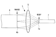
- the Koehler illumination unit 5 is an optical system that uses the light from the exit surface 4b of the rod integrator 4 to Koehler illuminate the incident surface 7a of the light guide 7 connected to the subsequent stage as will be described later. Specifically, the Koehler illumination unit 5 is arranged so that the illumination target is positioned on the rear combined focal plane of the lens unit, that is, the pupil plane P, and projects the light on the exit surface 4b onto the pupil plane P.
- the Koehler illumination part 5 which consists of two lenses is shown in FIG. 1, the lens structure of the Koehler illumination part 5 can be changed suitably.
- FIG. 3 is a diagram for explaining the operation of the Koehler illumination unit 5.
- light rays having the same emission angle among the light rays emitted from the respective positions of the emission surface 4 b of the rod integrator 4 are condensed at the same position on the pupil plane P by the Koehler illumination unit 5.
- the angle information included in the light L is converted into position information, that is, the angle unevenness is converted into the position unevenness, and the light L does not include the angle unevenness in the pupil plane P. Therefore, by arranging the incident surface 7 a of the light guide 7 on the pupil plane P of the Koehler illumination unit 5, the light L including the position unevenness and the angle unevenness is incident on the light guide 7.
- the Koehler illumination section 5 is shown simplified by a single lens.
- the illumination device 1 is connected to the endoscope so that the incident surface 7a of the light guide 7 is arranged on the pupil plane P of the Koehler illumination unit 5.
- the light guide 7 is provided in the elongated insertion portion provided in the endoscope over substantially the entire length of the insertion portion, guides the light L incident on the incident surface 7a from the illumination device 1 to the distal end of the insertion portion, It irradiates from the front-end
- the light L emitted from the light source 2 is first incident on the critical illumination unit 3 and condensed on the incident surface 4a of the rod integrator 4 at an appropriate magnification.
- the light L at this stage includes both angle unevenness and position unevenness, and the position unevenness among these is removed while the light is guided through the rod integrator 4.
- the light L in which the angle unevenness remains is incident on the Koehler illumination unit 5 from the rod integrator 4, and the angle unevenness is converted into the position unevenness in the Koehler illumination unit 5.
- the light L including the position unevenness and the angle unevenness is removed is incident on the light guide 7 of the endoscope.
- the illumination target X is irradiated with the light from which both the angle unevenness and the position unevenness are removed as the illumination light L ′.
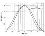
- the solid line in FIG. 2 indicates the light distribution characteristic of the light L (illumination light L ′) on the exit surface 7 b of the light guide 7. 2 that the light distribution characteristic of the illumination light L ′ is improved and is symmetric with respect to the optical axis A.
- the position unevenness among the angle unevenness and the position unevenness included in the light L is first removed by the rod integrator 4, and then the angle unevenness is converted into the position unevenness by the Kohler illumination unit 5. Then, the position unevenness is removed by the light guide 7. As a result, it is possible to irradiate the illumination target X with the illumination light L ′ having no angle unevenness and position unevenness.
- a light modulation element (LCD or LCOS) provided in the projector is used instead of the light guide 7.
- the light guide 7 provided in the endoscope is used as a configuration for removing the positional unevenness generated by the Koehler illumination section 5, but instead, the Koehler illumination section 5 is used.
- another light guide member such as a rod integrator or a light guide may be provided.
- the illuminating device 1 which concerns on the 2nd Embodiment of this invention is demonstrated with reference to FIGS.
- the configuration different from the first embodiment will be mainly described, and the configuration common to the first embodiment will be denoted by the same reference numerals and the description thereof will be omitted.
- the illuminating device 1 according to this embodiment includes three light sources 21, 22, and 23 and lights L 1, L 2, and L 3 from the light sources 21, 22, and 23 on the same optical axis A.
- the second embodiment is mainly different from the first embodiment in that it includes a synthesizing unit 6 for synthesizing.
- the light sources 21, 22, and 23 emit light L1, L2, and L3 having different colors.
- the light sources 21, 22, and 23 are semiconductor light sources such as LEDs that emit blue, green, and red monochromatic lights L1, L2, and L3, respectively.
- the light L1, L2, and L3 emitted from the different light sources 21, 22, and 23 generally have different light distribution characteristics.
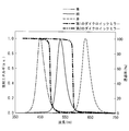
- FIG. 5 shows the spectra of the lights L1, L2, and L3 emitted from the three light sources 21, 22, and 23, and FIG. 6 shows the light distribution characteristics of these three lights L1, L2, and L3.
- the light distribution characteristics differ depending on the lights L1, L2, and L3.
- the vertical axis indicates the intensity normalized with the maximum intensity of each light L1, L2, L3 as 1.
- the critical illumination unit 3 has three light sources 21, 22, 23 (specifically, for example, the light emitting surface of each LED) and the incident surface 4 a of the rod integrator 4 at an optically conjugate position. It is configured to be arranged.
- the critical illumination unit 3 includes three first condenser lenses 31 arranged immediately after the respective light sources 21, 22, and 23, and three lights synthesized on the optical axis A by the synthesis unit 6 as described later.
- a single second condenser lens 32 that condenses L1, L2, and L3 on the incident surface 4a of the rod integrator 4 is provided.
- the combining unit 6 is arranged in series on the outgoing optical axis A of the light source 21, and reflects the light L2 and L3 from the light sources 22 and 23 in the direction along the optical axis A and the second dichroic mirror 61 and the second dichroic mirror 61, respectively.
- a dichroic mirror 62 is provided. As shown in FIG. 5, the two dichroic mirrors 61 and 62 have the property of a short-pass filter that selectively transmits light having a wavelength shorter than a predetermined wavelength. Specifically, the first dichroic mirror 61 transmits the blue light L1 from the light source 21 and reflects the green light L2 from the light source 22. The second dichroic mirror 62 on the rod integrator 4 side transmits the blue light L1 and the green light L2 from the dichroic mirror 61, and reflects the red light L3 from the light source 23.
- the incident surface 7a of the light guide 7 is arranged on the pupil plane P of the Koehler illumination unit 5.
- the illumination device 1 is connected to the endoscope.
- the three lights L1, L2, and L3 emitted from the three light sources 2 are first incident on the critical illumination unit 3.
- the three lights L 1, L 2, and L 3 are combined on the single optical axis A by the combining unit 6 and condensed on the incident surface 4 a of the rod integrator 4 at an appropriate magnification. Since the actions in the rod integrator 4, the Köhler illumination unit 5, and the light guide 7 are the same as those in the first embodiment, description thereof is omitted.
- the position unevenness among the angle unevenness and the position unevenness included in the lights L1, L2, and L3 is first removed by the rod integrator 4, and then the angular unevenness is detected by the Koehler illumination unit 5. After being converted into unevenness, the unevenness of position is removed by the light guide 7. As a result, it is possible to irradiate the illumination target X with the illumination light L ′ having no angle unevenness and position unevenness.
- the light distribution characteristics of all the lights L1, L2, and L3 are improved so as to be substantially the same as each other. Can be irradiated.
- FIG. 8 shows the light distribution characteristics of the three lights L1, L2, and L3 on the exit surface 7b of the light guide 7. From FIG. 8, it can be seen that the illumination light L ′ includes the three colors of light L1, L2, and L3 at a certain ratio at any angle and has a uniform color.
- the following effects can be obtained with respect to color unevenness. That is, when assembling optical components such as the light sources 21, 22, 23, the condenser lenses 31, 32, and the dichroic mirrors 61, 62, deviations may occur in the positions and angles of the optical components. Due to this assembly error, the optical axes and light distribution characteristics of the light sources 21, 22, and 23 change or the amount of light decreases, resulting in uneven color of the illumination light L '. The influence of the assembly error on the color unevenness of the illumination light L ′ increases as the number of light sources 21, 22, and 23 for color synthesis increases.
- the half-value angles of the lights L1, L2, and L3 emitted from the light sources 21, 22, and 23 vary depending on the LED specifications, particularly the emission wavelength. Therefore, when one illumination light L ′ is generated from light L1, L2, L3 of a plurality of colors as in the present embodiment, color unevenness tends to appear more prominently.
Landscapes
- Physics & Mathematics (AREA)
- General Physics & Mathematics (AREA)
- Projection Apparatus (AREA)
- Instruments For Viewing The Inside Of Hollow Bodies (AREA)
- Non-Portable Lighting Devices Or Systems Thereof (AREA)
- Devices For Indicating Variable Information By Combining Individual Elements (AREA)
- Light Guides In General And Applications Therefor (AREA)
- Liquid Crystal (AREA)
Abstract
L'invention concerne un dispositif d'éclairage (1) équipé de : une source de lumière (2); un organe guidant la lumière (4) qui a une face d'entrée (4a), à travers laquelle la lumière (L) entrante provenant de la source de lumière (2) entre, et une face de sortie (4b) à travers laquelle la lumière (L) sort, et guide la lumière (L) de la face d'entrée (4a) à la face de sortie (4b) tout en réfléchissant la lumière à l'intérieur de l'organe guidant la lumière; et une unité d'éclairage de Koehler (5) permettant d'émettre la lumière (L) émise depuis la face de sortie (4b) vers un objet à éclairer, ladite unité d'éclairage de Koehler (5) ayant une disposition telle que l'objet à éclairer est positionné dans un plan de pupille (P) de tout le système optique, lequel s'étend de la source de lumière (2) à l'unité d'éclairage de Koehler (5).
Applications Claiming Priority (2)
| Application Number | Priority Date | Filing Date | Title |
|---|---|---|---|
| JP2012288323A JP2014130761A (ja) | 2012-12-28 | 2012-12-28 | 照明装置 |
| JP2012-288323 | 2012-12-28 |
Publications (1)
| Publication Number | Publication Date |
|---|---|
| WO2014103448A1 true WO2014103448A1 (fr) | 2014-07-03 |
Family
ID=51020551
Family Applications (1)
| Application Number | Title | Priority Date | Filing Date |
|---|---|---|---|
| PCT/JP2013/075577 Ceased WO2014103448A1 (fr) | 2012-12-28 | 2013-09-20 | Dispositif d'éclairage |
Country Status (2)
| Country | Link |
|---|---|
| JP (1) | JP2014130761A (fr) |
| WO (1) | WO2014103448A1 (fr) |
Cited By (3)
| Publication number | Priority date | Publication date | Assignee | Title |
|---|---|---|---|---|
| CN113993438A (zh) * | 2019-06-21 | 2022-01-28 | 奥林巴斯株式会社 | 照明光学系统和照明装置 |
| CN117148652A (zh) * | 2023-08-31 | 2023-12-01 | 合肥市纳诺半导体有限公司 | 一种晶圆检测照明装置及其使用方法 |
| WO2026076066A1 (fr) * | 2024-10-01 | 2026-04-09 | 10X Genomics, Inc. | Systèmes et procédés d'éclairage d'un échantillon |
Families Citing this family (1)
| Publication number | Priority date | Publication date | Assignee | Title |
|---|---|---|---|---|
| JP7200781B2 (ja) * | 2019-03-20 | 2023-01-10 | 株式会社リコー | 光源装置、画像投射装置及び光源光学系 |
Citations (2)
| Publication number | Priority date | Publication date | Assignee | Title |
|---|---|---|---|---|
| JPH11326826A (ja) * | 1998-05-13 | 1999-11-26 | Sony Corp | 照明方法及び照明装置 |
| JP2005159068A (ja) * | 2003-11-27 | 2005-06-16 | Nikon Corp | 照明光学装置及び露光装置 |
-
2012
- 2012-12-28 JP JP2012288323A patent/JP2014130761A/ja active Pending
-
2013
- 2013-09-20 WO PCT/JP2013/075577 patent/WO2014103448A1/fr not_active Ceased
Patent Citations (2)
| Publication number | Priority date | Publication date | Assignee | Title |
|---|---|---|---|---|
| JPH11326826A (ja) * | 1998-05-13 | 1999-11-26 | Sony Corp | 照明方法及び照明装置 |
| JP2005159068A (ja) * | 2003-11-27 | 2005-06-16 | Nikon Corp | 照明光学装置及び露光装置 |
Cited By (3)
| Publication number | Priority date | Publication date | Assignee | Title |
|---|---|---|---|---|
| CN113993438A (zh) * | 2019-06-21 | 2022-01-28 | 奥林巴斯株式会社 | 照明光学系统和照明装置 |
| CN117148652A (zh) * | 2023-08-31 | 2023-12-01 | 合肥市纳诺半导体有限公司 | 一种晶圆检测照明装置及其使用方法 |
| WO2026076066A1 (fr) * | 2024-10-01 | 2026-04-09 | 10X Genomics, Inc. | Systèmes et procédés d'éclairage d'un échantillon |
Also Published As
| Publication number | Publication date |
|---|---|
| JP2014130761A (ja) | 2014-07-10 |
Similar Documents
| Publication | Publication Date | Title |
|---|---|---|
| CN104160204B (zh) | 具有泵浦激光器列的发光装置和用于运行该发光装置的方法 | |
| CN106415359B (zh) | 照明装置、方法与医疗成像系统 | |
| JP6762073B2 (ja) | 照明装置および投影装置 | |
| JP4817632B2 (ja) | Ledファイバ光源装置及びそれを用いた内視鏡 | |
| JP5914878B2 (ja) | 光源装置及び投写型表示装置 | |
| TWI506224B (zh) | 照明裝置 | |
| JP4477070B2 (ja) | 照明装置及びそれを用いた投写型表示装置 | |
| JP2012141411A (ja) | 光源装置 | |
| TWI545385B (zh) | 光源單元以及投影式顯示裝置 | |
| WO2014068742A1 (fr) | Dispositif de source lumineuse et dispositif d'affichage d'image de type à projection | |
| JP7071101B2 (ja) | 光源装置および画像投射装置 | |
| WO2014196020A1 (fr) | Système optique d'éclairage et projecteur | |
| JP2000180962A (ja) | プロジェクション照明装置 | |
| JP5598968B2 (ja) | 医用光学観察装置の照明デバイス用の光源構成 | |
| JP4411923B2 (ja) | 照明装置、表示装置及びプロジェクタ | |
| JP2015132666A (ja) | 光源光学系、光源装置およびプロジェクタ装置 | |
| WO2014103448A1 (fr) | Dispositif d'éclairage | |
| JP2017227809A (ja) | 照明装置およびこれを用いた投射型表示装置 | |
| US20100118411A1 (en) | Integrator and illuminating apparatus using the integrator | |
| JP2007047707A (ja) | 照明装置、光変調装置及び投射型表示装置 | |
| JP2006122251A (ja) | Ledファイバ光源装置及びそれを用いた内視鏡装置 | |
| JP2005283918A (ja) | 照明用光源装置 | |
| JP2005300823A (ja) | 光学ユニット、および照明装置、投写型表示装置 | |
| US10877283B1 (en) | Light source module | |
| JP2014023630A (ja) | 光源ユニット及び電子内視鏡装置 |
Legal Events
| Date | Code | Title | Description |
|---|---|---|---|
| 121 | Ep: the epo has been informed by wipo that ep was designated in this application |
Ref document number: 13868582 Country of ref document: EP Kind code of ref document: A1 |
|
| NENP | Non-entry into the national phase |
Ref country code: DE |
|
| 122 | Ep: pct application non-entry in european phase |
Ref document number: 13868582 Country of ref document: EP Kind code of ref document: A1 |