WO2014103559A2 - Objectif à focal variable et dispositif d'imagerie - Google Patents
Objectif à focal variable et dispositif d'imagerie Download PDFInfo
- Publication number
- WO2014103559A2 WO2014103559A2 PCT/JP2013/081028 JP2013081028W WO2014103559A2 WO 2014103559 A2 WO2014103559 A2 WO 2014103559A2 JP 2013081028 W JP2013081028 W JP 2013081028W WO 2014103559 A2 WO2014103559 A2 WO 2014103559A2
- Authority
- WO
- WIPO (PCT)
- Prior art keywords
- lens
- lens group
- positive
- group
- focal length
- Prior art date
- Legal status (The legal status is an assumption and is not a legal conclusion. Google has not performed a legal analysis and makes no representation as to the accuracy of the status listed.)
- Ceased
Links
Images




Classifications
-
- G—PHYSICS
- G02—OPTICS
- G02B—OPTICAL ELEMENTS, SYSTEMS OR APPARATUS
- G02B15/00—Optical objectives with means for varying the magnification
- G02B15/14—Optical objectives with means for varying the magnification by axial movement of one or more lenses or groups of lenses relative to the image plane for continuously varying the equivalent focal length of the objective
- G02B15/16—Optical objectives with means for varying the magnification by axial movement of one or more lenses or groups of lenses relative to the image plane for continuously varying the equivalent focal length of the objective with interdependent non-linearly related movements between one lens or lens group, and another lens or lens group
- G02B15/163—Optical objectives with means for varying the magnification by axial movement of one or more lenses or groups of lenses relative to the image plane for continuously varying the equivalent focal length of the objective with interdependent non-linearly related movements between one lens or lens group, and another lens or lens group having a first movable lens or lens group and a second movable lens or lens group, both in front of a fixed lens or lens group
- G02B15/167—Optical objectives with means for varying the magnification by axial movement of one or more lenses or groups of lenses relative to the image plane for continuously varying the equivalent focal length of the objective with interdependent non-linearly related movements between one lens or lens group, and another lens or lens group having a first movable lens or lens group and a second movable lens or lens group, both in front of a fixed lens or lens group having an additional fixed front lens or group of lenses
- G02B15/173—Optical objectives with means for varying the magnification by axial movement of one or more lenses or groups of lenses relative to the image plane for continuously varying the equivalent focal length of the objective with interdependent non-linearly related movements between one lens or lens group, and another lens or lens group having a first movable lens or lens group and a second movable lens or lens group, both in front of a fixed lens or lens group having an additional fixed front lens or group of lenses arranged +-+
-
- G—PHYSICS
- G02—OPTICS
- G02B—OPTICAL ELEMENTS, SYSTEMS OR APPARATUS
- G02B13/00—Optical objectives specially designed for the purposes specified below
- G02B13/001—Miniaturised objectives for electronic devices, e.g. portable telephones, webcams, PDAs, small digital cameras
- G02B13/009—Miniaturised objectives for electronic devices, e.g. portable telephones, webcams, PDAs, small digital cameras having zoom function
-
- G—PHYSICS
- G02—OPTICS
- G02B—OPTICAL ELEMENTS, SYSTEMS OR APPARATUS
- G02B15/00—Optical objectives with means for varying the magnification
- G02B15/14—Optical objectives with means for varying the magnification by axial movement of one or more lenses or groups of lenses relative to the image plane for continuously varying the equivalent focal length of the objective
- G02B15/145—Optical objectives with means for varying the magnification by axial movement of one or more lenses or groups of lenses relative to the image plane for continuously varying the equivalent focal length of the objective having five groups only
- G02B15/1451—Optical objectives with means for varying the magnification by axial movement of one or more lenses or groups of lenses relative to the image plane for continuously varying the equivalent focal length of the objective having five groups only the first group being positive
- G02B15/145129—Optical objectives with means for varying the magnification by axial movement of one or more lenses or groups of lenses relative to the image plane for continuously varying the equivalent focal length of the objective having five groups only the first group being positive arranged +-+++
Definitions
- This technology relates to zoom lenses and imaging devices such as digital cameras and video cameras. More specifically, the present invention relates to a zoom lens and an image pickup apparatus that achieve a small diameter while achieving a high zoom ratio and a wide angle of view.
- a four-group inner zoom lens is known in which the first lens group and the third lens group are fixed and the second lens group and the fourth lens group are moved (see, for example, Patent Document 1).
- the second lens group is moved in the optical axis direction to mainly perform zooming
- the fourth lens group is moved in the optical axis direction to perform focus position correction and focusing by zooming. ing.
- zooming and focusing are performed by fixing the first lens group and the third lens group and moving the second lens group and the fourth lens group.
- an inner focus type zoom lens has a problem that the lens diameter of the first lens group becomes larger than that of the other groups.
- an increase in the diameter of the first lens group means that the radial size of the entire imaging apparatus is enlarged, which is not desirable.
- This technology was created in view of such a situation, and aims to achieve a reduction in diameter while achieving a wide angle of view at a high zoom ratio in a zoom lens.
- the present technology has been made to solve the above-described problems, and the first side surface of the first lens group has a positive refractive index and a fixed position in order from the object side.
- a fourth lens group whose position is movable for focusing The first lens group includes, in order from the object side, a negative lens, a first positive lens, and a second positive lens. And a zoom lens that satisfies the following conditional expressions (a), (b), and (c).
- fw is the focal length of the entire lens system at the wide-angle end
- ft is the focal length of the entire lens system at the telephoto end
- f1 is the focal length of the first lens unit
- fL1 is the focal length of the negative lens of the first lens unit.
- conditional expression (d) may be further satisfied.
- f1L is the focal length of the second positive lens of the first lens group.
- conditional expression (e) may be further satisfied.
- SAG_f1L_R1 is a sag amount from the lens apex on the object side surface of the second positive lens of the first lens group to the lens optical effective diameter.
- At least one surface of the second positive lens in the first lens group may be an aspherical surface.
- the second aspect of the present technology includes, in order from the object side, a first lens group having a positive refractive index and a fixed position, and an optical axis having a negative refractive power for zooming.
- a second lens group whose position is movable in the direction, a third lens group having a positive refractive power, and a fourth lens group whose position is movable for correcting and focusing the focal position by zooming.
- the first lens group includes, in order from the object side, a negative lens, a first positive lens, and a second positive lens.
- the following conditional expressions (a) and (b) And (c) and an imaging device that includes an imaging element that converts an optical image formed by the zoom lens into an electrical signal.
- the zoom lens can achieve an excellent effect that a small diameter can be achieved while achieving a wide angle of view with a high zoom ratio.
- the zoom lens according to the present disclosure includes, in order from the object side, a first lens group GR1 having a positive refractive index and a fixed position, a negative refractive power, and a position in the optical axis direction for zooming.
- a second lens group GR2 that can move, a third group lens group GR3 having positive refractive power, and a fourth lens whose position can be moved for focal point correction and focusing by zooming It is comprised from group GR4.
- the first lens group includes, in order from the object side, a negative lens L11, a first positive lens L12, and a second positive lens L13.
- the zoom lens according to the present disclosure satisfies the following conditional expressions (a), (b), and (c).
- fw focal length of the entire lens system at the wide-angle end
- ft focal length of the entire lens system at the telephoto end
- f1 focal length of the entire lens system at the telephoto end
- f1 focal length fL of the first lens group
- GR1 focal length of the negative lens L11 of the first lens group GR1.
- Conditional expression (a) represents a focal length ratio of the zoom lens, that is, a condition regarding magnification.
- Conditional expression (b) defines the focal length ratio of the first lens group GR1, that is, the refractive power. When the focal length of the first lens group GR1 exceeds the upper limit of the conditional expression (b), the refractive power of the first lens group GR1 becomes weak, and the radial size of the first lens group GR1 becomes enlarged.
- conditional expression (b) defines the focal length ratio of the negative lens L11, that is, the refractive power. If the lower limit of conditional expression (c) is exceeded, the effect of lowering the beam height is weakened, making it difficult to achieve a reduction in diameter. If the upper limit of conditional expression (c) is exceeded, the refractive power of the first negative lens in the first lens group GR1 becomes too strong, making it difficult to correct aberrations.
- conditional expressions (a), (b), and (c) are changed to the ranges of the following conditional expressions (a ′), (b ′), and (c ′), respectively. It is more desirable to set.
- conditional expression (d) 9.5 ⁇ f1L / fw ⁇ 13.7
- f1L The focal length of the second positive lens L13 of the first lens group GR1.
- conditional expression (d) defines the refractive power of the lens arranged closest to the imaging surface of the first lens group GR1. If the lower limit of conditional expression (d) is not reached, the positive refractive power of the entire first lens group GR1 increases, which is advantageous for reducing the diameter, but aberrations occur and it is difficult to ensure performance. In particular, the spherical aberration on the telephoto side is overcorrected, leading to performance degradation.
- conditional expression (d) is appropriately set in view of this.
- the refractive power of the first lens group GR1 is defined by the second positive lens L13. The further preferable effect by (d) can be expected.
- the zoom lens according to the present disclosure further satisfies the following conditional expression (e).
- Conditional expression (e) 0.6 ⁇ SAG_f1L_R1 / fw ⁇ 1.16
- SAG_f1L_R1 A sag amount from the lens apex on the object side surface of the second positive lens L13 of the first lens group GR1 to the lens optical effective diameter.
- the zoom lens according to the present disclosure can efficiently correct the aberration from the intermediate range to the telephoto end while maintaining the small diameter of the first lens group GR1 while having a wide angle.
- Conditional expression (e) defines the amount of sag on the object side surface (R1 surface) of the lens disposed closest to the image plane of the first lens group GR1, and is in a range of conditions that are particularly advantageous for aberration correction. Yes. If the conditional expression (e) is not satisfied, it will be difficult to correct curvature of field at the wide-angle end and correction of spherical aberration and coma from the intermediate range to the telephoto end. In particular, in the optical system of the present disclosure, correcting the above-described aberration group on the object side surface of the lens disposed closest to the image plane of the first lens group GR1 has a significant effect on performance.
- At least one surface of the second positive lens L13 of the first lens group GR1 is an aspherical surface.
- the zoom lens according to the present disclosure can efficiently correct the aberration from the intermediate range to the telephoto end while maintaining the small diameter of the first lens group GR1 while having a wide angle.
- the optical system of the present disclosure is characterized in that the refractive power of the first lens group GR1 is stronger than the refractive power of the first lens group in the conventional inner zoom optical system in order to reduce the diameter. In order to correct various aberrations occurring in the first lens group, it is very reasonable to arrange an aspherical surface in the first lens group GR1.
- the zoom lens of the present disclosure achieves both a wide field angle of 33 mm or less and a front lens diameter reduction in a 35 mm equivalent field angle, and a high zoom ratio of about 18 to 42 times. Make it possible.
- si indicates a surface number that means the i-th surface counted from the object side.
- Ri indicates the radius of curvature of the i-th surface counted from the object side.
- Di indicates an axial upper surface distance between the i-th surface and the (i + 1) -th surface counted from the object side.
- Ni indicates a refractive index with respect to d-line (wavelength: 587.6 nm) of a glass material or material having an i-th surface on the object side.
- ⁇ i indicates the Abbe number with respect to the d-line of the glass material or material having the i-th surface on the object side.
- “INFINITY” regarding the radius of curvature indicates that the surface is a flat surface. Further, “ASP” attached to the surface number indicates that the surface is formed of an aspherical shape. “F” indicates the focal length of the entire lens system. “Fno” indicates an open F value (F number). “ ⁇ ” indicates a half angle of view.
- zoom lenses used in the embodiments have an aspheric lens surface as described above.
- the distance (sag) in the optical axis direction from the apex of the lens surface is “x”
- the height in the direction perpendicular to the optical axis is “y”
- the paraxial curvature at the lens apex is “c”
- the conic constant Is alliance, x cy 2 / (1+ (1 ⁇ (1 + excellent) c 2 y 2 ) 1/2 ) + A4y 4 + A6y 6 + A8y 8 + A10y 10
- Shall be defined by A4, A6, A8, and A10 are fourth-order, sixth-order, eighth-order, and tenth-order aspheric coefficients, respectively.
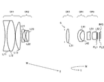
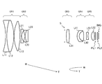
- FIG. 1 is a diagram illustrating a lens configuration of a zoom lens according to the first embodiment of the present technology.
- the zoom lens according to the first embodiment includes, in order from the object side, the first lens group GR1, the second lens group GR2, the third lens group GR3, the fourth lens group GR4, and the fifth lens group GR5. And are arranged.
- the first lens group GR1 has a positive refractive power.
- the second lens group GR2 has a negative refractive power.
- the third lens group GR3 has a positive refractive power.
- the fourth lens group GR4 has a positive refractive power.
- the fifth lens group GR5 has a positive refractive power.
- the first lens group GR1 is composed of three lenses, a cemented lens of a negative lens L11 and a positive lens L12, and a positive lens L13 in order from the object side.
- the positive lens L13 is configured by an aspheric lens.
- the second lens group GR2 is composed of three lenses of a negative lens L21, a negative lens L22, and a positive lens L23 in order from the object side.
- the negative lens L21 is configured by an aspheric lens.
- the third lens group GR3 is composed of one positive lens L31.
- the positive lens L31 is configured by an aspheric lens.
- the fourth lens group GR4 is constituted by a cemented lens of a negative lens L41 and a positive lens L42.
- the positive lens L42 is configured by an aspheric lens.
- the fifth lens group GR5 has, in order from the object side, a movable group that is movable in a direction perpendicular to the optical axis for anti-vibration configured by the lens L51 having a negative refractive power, and a positive refractive power.
- the lens L52 includes a fixed group whose position is fixed at all times.
- the lenses L51 and L52 are both constituted by aspherical lenses.
- a diaphragm S is disposed between the second lens group GR2 and the third lens group GR3.
- Filters FL1 and FL2 are disposed between the fifth lens group GR5 and the image plane IMG.
- Table 1 shows lens data of Numerical Example 1 in which specific numerical values are applied to the zoom lens according to the first embodiment.
- Both surfaces (the 17th surface and the 18th surface) of the lens L51 and both surfaces (the 19th surface and the 20th surface) of the positive lens L52 of the fifth lens group GR5 are aspherical.
- Table 2 shows the conic constants ⁇ , fourth-order, sixth-order, eighth-order, and tenth-order aspheric coefficients A4, A6, A8, and A10 of these surfaces.
- Ei represents an exponential expression with a base of 10, that is, “10 ⁇ i ”.
- 0.12345E-05 It represents “0.12345 ⁇ 10 ⁇ 5 ”.
- Table 3 shows the focal length f, the F value Fno, and the half angle of view ⁇ in the wide-angle end state, the intermediate focal length state, and the telephoto end state of Numerical Example 1.
- the distance d5 between the first lens group GR1 and the second lens group GR2 and the second lens group GR2 are used.
- the distance d11 between the third lens group GR3 and the fourth lens group GR4, and the distance d19 between the fourth lens group GR4 and the fifth lens group GR5 are changed.
- Table 4 shows the variable intervals in the wide-angle end state, the intermediate focal length state, and the telephoto end state of each surface interval in this case.
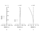
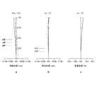
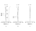
- FIG. 2 shows aberration diagrams in the wide-angle end state
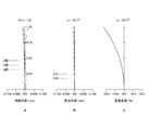
- FIG. 3 shows the intermediate focal length state
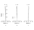
- FIG. 4 shows the aberrations in the telephoto end state.
- a is a spherical aberration diagram
- b is an astigmatism diagram (field curvature diagram)
- c is a distortion diagram.
- the solid line indicates the value at the d-line (587.6 nm)
- the broken line indicates the value at the c-line (wavelength 656.3 nm)
- the alternate long and short dash line indicates the value at the g-line (wavelength 435.8 nm).
- the solid line indicates the value on the sagittal image plane of the d line
- the broken line indicates the value on the meridional image plane of the d line.
- the solid line shows the value at the d-line.
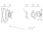
- FIG. 5 is a diagram illustrating a lens configuration of a zoom lens according to the second embodiment of the present technology.
- the zoom lens according to the second embodiment includes, in order from the object side, the first lens group GR1, the second lens group GR2, the third lens group GR3, the fourth lens group GR4, and the fifth lens group GR5. And are arranged.
- the first lens group GR1 has a positive refractive power.
- the second lens group GR2 has a negative refractive power.
- the third lens group GR3 has a positive refractive power.
- the fourth lens group GR4 has a positive refractive power.
- the fifth lens group GR5 has a positive refractive power.
- the first lens group GR1 is composed of three lenses, a cemented lens of a negative lens L11 and a positive lens L12, and a positive lens L13 in order from the object side.
- the positive lens L13 is configured by an aspheric lens.
- the second lens group GR2 is composed of three lenses of a negative lens L21, a negative lens L22, and a positive lens L23 in order from the object side.
- the negative lens L21 is configured by an aspheric lens.
- the third lens group GR3 is composed of one positive lens L31.
- the positive lens L31 is configured by an aspheric lens.
- the fourth lens group GR4 is constituted by a cemented lens of a negative lens L41 and a positive lens L42.
- the positive lens L42 is configured by an aspheric lens.
- the fifth lens group GR5 has, in order from the object side, a movable group that is movable in a direction perpendicular to the optical axis for anti-vibration configured by the lens L51 having a negative refractive power, and a positive refractive power.
- the lens L52 includes a fixed group whose position is fixed at all times.
- the lenses L51 and L52 are both constituted by aspherical lenses.
- a diaphragm S is disposed between the second lens group GR2 and the third lens group GR3.
- Filters FL1 and FL2 are disposed between the fifth lens group GR5 and the image plane IMG.
- Table 5 shows lens data of Numerical Example 2 in which specific numerical values are applied to the zoom lens according to the second embodiment.
- Both surfaces (the 17th surface and the 18th surface) of the lens L51 and both surfaces (the 19th surface and the 20th surface) of the positive lens L52 of the fifth lens group GR5 are aspherical.
- Table 6 shows the conic constant ⁇ , fourth order, sixth order, eighth order and tenth order aspherical coefficients A4, A6, A8 and A10 of these surfaces.
- Table 7 shows the focal length f, the F value Fno, and the half angle of view ⁇ in the wide-angle end state, the intermediate focal length state, and the telephoto end state of Numerical Example 2.
- the distance d5 between the first lens group GR1 and the second lens group GR2 and the second lens group GR2 are used.
- the distance d11 between the third lens group GR3 and the fourth lens group GR4, and the distance d19 between the fourth lens group GR4 and the fifth lens group GR5 are changed.
- Table 8 shows the variable intervals in the wide-angle end state, the intermediate focal length state, and the telephoto end state of each surface interval in this case.
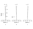
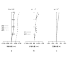
- [Aberration of zoom lens] 6 to 8 are graphs showing various aberrations of the zoom lens according to the second embodiment of the present technology. 6 shows aberration diagrams in the wide-angle end state, FIG. 7 shows the intermediate focal length state, and FIG. 8 shows the aberrations in the telephoto end state.
- a is a spherical aberration diagram
- b is an astigmatism diagram (field curvature diagram)
- c is a distortion diagram.
- FIG. 9 is a diagram illustrating a lens configuration of a zoom lens according to the third embodiment of the present technology.
- the zoom lens according to the third embodiment includes, in order from the object side, the first lens group GR1, the second lens group GR2, the third lens group GR3, the fourth lens group GR4, and the fifth lens group GR5. And are arranged.
- the first lens group GR1 has a positive refractive power.
- the second lens group GR2 has a negative refractive power.
- the third lens group GR3 has a positive refractive power.
- the fourth lens group GR4 has a positive refractive power.
- the fifth lens group GR5 has a positive refractive power.
- the first lens group GR1 is composed of three lenses, a cemented lens of a negative lens L11 and a positive lens L12, and a positive lens L13 in order from the object side.
- the positive lens L13 is configured by an aspheric lens.
- the second lens group GR2 is composed of three lenses of a negative lens L21, a negative lens L22, and a positive lens L23 in order from the object side.
- the negative lens L21 is configured by an aspheric lens.
- the third lens group GR3 is composed of one positive lens L31.
- the positive lens L31 is configured by an aspheric lens.
- the fourth lens group GR4 is constituted by a cemented lens of a negative lens L41 and a positive lens L42.
- the positive lens L42 is configured by an aspheric lens.
- the fifth lens group GR5 has, in order from the object side, a movable group that is movable in a direction perpendicular to the optical axis for anti-vibration configured by the lens L51 having a negative refractive power, and a positive refractive power.
- the lens L52 includes a fixed group whose position is fixed at all times.
- the lenses L51 and L52 are both constituted by aspherical lenses.
- a diaphragm S is disposed between the second lens group GR2 and the third lens group GR3.
- Filters FL1 and FL2 are disposed between the fifth lens group GR5 and the image plane IMG.
- Table 9 shows lens data of Numerical Example 3 in which specific numerical values are applied to the zoom lens according to the third embodiment.
- Both surfaces (the 17th surface and the 18th surface) of the lens L51 and both surfaces (the 19th surface and the 20th surface) of the positive lens L52 of the fifth lens group GR5 are aspherical.
- Table 10 shows the conic constant ⁇ , fourth order, sixth order, eighth order and tenth order aspherical coefficients A4, A6, A8 and A10 of these surfaces.
- Table 11 shows the focal length f, the F value Fno, and the half angle of view ⁇ in the wide-angle end state, the intermediate focal length state, and the telephoto end state of Numerical Example 3.
- the distance d5 between the first lens group GR1 and the second lens group GR2 and the second lens group GR2 are used.
- the distance d11 between the third lens group GR3 and the fourth lens group GR4, and the distance d19 between the fourth lens group GR4 and the fifth lens group GR5 are changed.
- Table 12 shows variable intervals in the wide-angle end state, the intermediate focal length state, and the telephoto end state of each surface interval in this case.
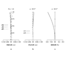
- FIG. 10 to 12 are graphs showing various aberrations of the zoom lens according to the third embodiment of the present technology.
- FIG. 10 shows aberration diagrams in the wide-angle end state
- FIG. 11 shows the intermediate focal length state
- FIG. 12 shows the aberrations in the telephoto end state.
- a is a spherical aberration diagram
- b is an astigmatism diagram (field curvature diagram)
- c is a distortion diagram.
- FIG. 13 is a diagram illustrating a lens configuration of a zoom lens according to the fourth embodiment of the present technology.
- the zoom lens according to the fourth embodiment includes, in order from the object side, the first lens group GR1, the second lens group GR2, the third lens group GR3, the fourth lens group GR4, and the fifth lens group GR5. And are arranged.
- the first lens group GR1 has a positive refractive power.
- the second lens group GR2 has a negative refractive power.
- the third lens group GR3 has a positive refractive power.
- the fourth lens group GR4 has a positive refractive power.
- the fifth lens group GR5 has a positive refractive power.
- the first lens group GR1 is composed of three lenses, a cemented lens of a negative lens L11 and a positive lens L12, and a positive lens L13 in order from the object side.
- the positive lens L13 is configured by an aspheric lens.
- the second lens group GR2 is composed of three lenses of a negative lens L21, a negative lens L22, and a positive lens L23 in order from the object side.
- the negative lens L21 is configured by an aspheric lens.
- the third lens group GR3 is composed of one positive lens L31.
- the positive lens L31 is configured by an aspheric lens.
- the fourth lens group GR4 is constituted by a cemented lens of a negative lens L41 and a positive lens L42.
- the positive lens L42 is configured by an aspheric lens.
- the fifth lens group GR5 has, in order from the object side, a movable group that is movable in a direction perpendicular to the optical axis for anti-vibration configured by the lens L51 having a negative refractive power, and a positive refractive power.
- the lens L52 includes a fixed group whose position is fixed at all times.
- the lenses L51 and L52 are both constituted by aspherical lenses.
- a diaphragm S is disposed between the second lens group GR2 and the third lens group GR3.
- Filters FL1 and FL2 are disposed between the fifth lens group GR5 and the image plane IMG.
- Table 13 shows lens data of a numerical example 4 in which specific numerical values are applied to the zoom lens according to the fourth embodiment.
- Both surfaces (the 17th surface and the 18th surface) of the lens L51 and both surfaces (the 19th surface and the 20th surface) of the positive lens L52 of the fifth lens group GR5 are aspherical.
- Table 14 shows the conic constant ⁇ , fourth-order, sixth-order, eighth-order and tenth-order aspheric coefficients A4, A6, A8 and A10 of these surfaces.
- Table 15 shows the focal length f, the F value Fno, and the half angle of view ⁇ in the wide angle end state, the intermediate focal length state, and the telephoto end state of Numerical Example 4.
- the distance d5 between the first lens group GR1 and the second lens group GR2 and the second lens group GR2 are used.
- the distance d11 between the third lens group GR3 and the fourth lens group GR4, and the distance d19 between the fourth lens group GR4 and the fifth lens group GR5 are changed.
- Table 16 shows variable intervals in the wide-angle end state, the intermediate focal length state, and the telephoto end state of each surface interval in this case.
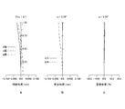
- FIG. 14 to 16 are graphs showing various aberrations of the zoom lens according to the fourth embodiment of the present technology.
- FIG. 14 shows aberrations in the wide-angle end state
- FIG. 15 shows the intermediate focal length state
- FIG. 16 shows the aberrations in the telephoto end state.
- a is a spherical aberration diagram
- b is an astigmatism diagram (field curvature diagram)
- c is a distortion diagram.
- Table 17 shows the values in Numerical Examples 1 to 4 of the first to fourth embodiments. As is apparent from this value, it is understood that the conditional expressions (a) to (e) are satisfied. Further, as shown in the respective aberration diagrams, it is understood that various aberrations are corrected in a balanced manner at the wide-angle end and the telephoto end.
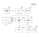
- FIG. 17 is a diagram illustrating an example in which the zoom lens according to the first to fourth embodiments of the present technology is applied to the imaging device 100.
- the imaging apparatus 100 includes a camera block 110, a camera signal processing unit 120, an image processing unit 130, a display unit 140, a reader / writer 150, a processor 160, an operation reception unit 170, and a lens drive control unit 180. It has.
- the camera block 110 has an imaging function, and includes the zoom lens 111 according to the first to fourth embodiments, and an imaging element 112 that converts an optical image formed by the zoom lens 111 into an electrical signal.
- an imaging device 112 for example, a photoelectric conversion device such as a charge coupled device (CCD) or a complementary metal-oxide semiconductor (CMOS) can be used.
- CCD charge coupled device
- CMOS complementary metal-oxide semiconductor
- the zoom lens 111 the lens groups of the first to fourth embodiments are simply shown as a single lens.
- the camera signal processing unit 120 performs signal processing such as analog-digital conversion of a captured image signal.
- the camera signal processing unit 120 converts the output signal from the image sensor 112 into a digital signal.
- the camera signal processing unit 120 performs various signal processing such as noise removal, image quality correction, and conversion to luminance / color difference signals.
- the image processing unit 130 performs recording / reproduction processing of an image signal.
- the image processing unit 130 performs compression encoding / decompression decoding processing of an image signal based on a predetermined image data format, conversion processing of data specifications such as resolution, and the like.
- the display unit 140 displays a photographed image or the like.
- the display unit 140 has a function of displaying the operation state in the operation receiving unit 170 and various data such as a captured image.
- the display unit 140 can be configured by, for example, a liquid crystal display (LCD: Liquid Crystal Display).
- the reader / writer 150 performs image signal writing and reading access to the memory card 190.
- the reader / writer 150 writes the image data encoded by the image processing unit 130 to the memory card 190 and reads the image data recorded on the memory card 190.
- the memory card 190 is a semiconductor memory that can be attached to and detached from a slot connected to the reader / writer 150, for example.
- the processor 160 controls the entire imaging apparatus.
- the processor 160 functions as a control processing unit that controls each circuit block provided in the imaging apparatus 100, and controls each circuit block based on an operation instruction signal or the like from the operation receiving unit 170.
- the operation accepting unit 170 accepts an operation from the user.
- the operation accepting unit 170 can be realized by, for example, a shutter release button for performing a shutter operation, a selection switch for selecting an operation mode, or the like.
- the operation instruction signal received by the operation receiving unit 170 is supplied to the processor 160.
- the lens drive control unit 180 controls the drive of the lens arranged in the camera block 110.
- the lens drive control unit 180 controls a motor (not shown) for driving each lens of the zoom lens 111 based on a control signal from the processor 160.
- an image signal captured by the camera block 110 under the control of the processor 160 is output to the display unit 140 via the camera signal processing unit 120 and displayed as a camera through image. Is done. Further, when an operation instruction signal for zooming is received by the operation receiving unit 170, the processor 160 outputs a control signal to the lens drive control unit 180, and a predetermined lens lens 111 is controlled based on the control of the lens drive control unit 180. The lens is moved.
- the captured image signal is output from the camera signal processing unit 120 to the image processing unit 130, subjected to compression encoding processing, and converted into digital data of a predetermined data format.
- the converted data is output to the reader / writer 150 and written to the memory card 190.
- Focusing is performed, for example, when the shutter release button is pressed halfway in the operation reception unit 170 or when it is fully pressed for recording (photographing).
- the lens drive control unit 180 moves a predetermined lens of the zoom lens 111 based on a control signal from the processor 160.
- predetermined image data is read from the memory card 190 by the reader / writer 150 in accordance with the operation received by the operation receiving unit 170. Then, after the decompression decoding process is performed by the image processing unit 130, the reproduced image signal is output to the display unit 140, and the reproduced image is displayed.
- the imaging apparatus 100 is assumed to be a digital still camera
- the imaging apparatus 100 is not limited to a digital still camera.
- the present invention can be widely applied to a digital video input / output device such as a digital video camera, a mobile phone incorporating a camera, and a PDA (Personal Digital Assistant) incorporating a camera.
- the inner focus type zoom lens by setting the focal length of the first lens group GR1 and the focal length of the negative lens L11 closest to the object side within an appropriate range, The diameter can be reduced while maintaining a wide angle of view with a high zoom ratio.
- the above-described embodiment shows an example for embodying the present technology, and the matters in the embodiment and the invention-specific matters in the claims have a corresponding relationship.
- the invention specific matter in the claims and the matter in the embodiment of the present technology having the same name as this have a corresponding relationship.
- the present technology is not limited to the embodiment, and can be embodied by making various modifications to the embodiment without departing from the gist thereof.
- this technique can also take the following structures.
- a first lens group having a positive refractive index and a fixed position, and a negative refractive power and the position can be moved in the optical axis direction for zooming.
- the first lens group includes, in order from the object side, a negative lens, a first positive lens, and a second positive lens.
- fw focal length of the entire lens system at the wide angle end
- ft focal length f1 of the entire lens system at the telephoto end
- f1 focal length fL1 of the first lens group
- focal length of the negative lens of the first lens group focal length of the negative lens of the first lens group.
- the zoom lens according to any one of (1) to (3) wherein at least one surface of the second positive lens of the first lens group is an aspherical surface.
- the zoom lens according to any one of (1) to (4) further including a lens having substantially no lens power.
- the first lens group having a positive refractive index and a fixed position, and a negative refractive power, and the position can be moved in the optical axis direction for zooming.
- a second lens group, a third lens group having a positive refractive power, and a fourth lens group whose position is movable for correcting and focusing the focal position by zooming The first lens group includes, in order from the object side, a negative lens, a first positive lens, and a second positive lens, and satisfies the following conditional expressions (a), (b), and (c) A lens, An imaging apparatus comprising: an imaging element that converts an optical image formed by the zoom lens into an electrical signal.
- fw focal length of the entire lens system at the wide angle end
- ft focal length f1 of the entire lens system at the telephoto end
- f1 focal length fL1 of the first lens group
- focal length of the negative lens of the first lens group (7)
Landscapes
- Physics & Mathematics (AREA)
- General Physics & Mathematics (AREA)
- Optics & Photonics (AREA)
- Nonlinear Science (AREA)
- Lenses (AREA)
Applications Claiming Priority (2)
| Application Number | Priority Date | Filing Date | Title |
|---|---|---|---|
| JP2012-287989 | 2012-12-28 | ||
| JP2012287989 | 2012-12-28 |
Publications (1)
| Publication Number | Publication Date |
|---|---|
| WO2014103559A2 true WO2014103559A2 (fr) | 2014-07-03 |
Family
ID=51022164
Family Applications (1)
| Application Number | Title | Priority Date | Filing Date |
|---|---|---|---|
| PCT/JP2013/081028 Ceased WO2014103559A2 (fr) | 2012-12-28 | 2013-11-18 | Objectif à focal variable et dispositif d'imagerie |
Country Status (1)
| Country | Link |
|---|---|
| WO (1) | WO2014103559A2 (fr) |
Cited By (2)
| Publication number | Priority date | Publication date | Assignee | Title |
|---|---|---|---|---|
| JP2023515995A (ja) * | 2020-02-29 | 2023-04-17 | 華為技術有限公司 | ズームレンズ、カメラモジュール、および携帯端末 |
| WO2026149514A1 (fr) * | 2025-01-10 | 2026-07-16 | 华为技术有限公司 | Objectif optique, module d'appareil de prise de vues et dispositif électronique |
-
2013
- 2013-11-18 WO PCT/JP2013/081028 patent/WO2014103559A2/fr not_active Ceased
Cited By (3)
| Publication number | Priority date | Publication date | Assignee | Title |
|---|---|---|---|---|
| JP2023515995A (ja) * | 2020-02-29 | 2023-04-17 | 華為技術有限公司 | ズームレンズ、カメラモジュール、および携帯端末 |
| US12436365B2 (en) | 2020-02-29 | 2025-10-07 | Huawei Technologies Co., Ltd. | Zoom lens, camera module, and mobile terminal |
| WO2026149514A1 (fr) * | 2025-01-10 | 2026-07-16 | 华为技术有限公司 | Objectif optique, module d'appareil de prise de vues et dispositif électronique |
Similar Documents
| Publication | Publication Date | Title |
|---|---|---|
| US8520318B2 (en) | Zoom lens and imaging apparatus | |
| JP4059228B2 (ja) | ズームレンズ及び撮像装置 | |
| JP5387392B2 (ja) | ズームレンズ及び撮像装置 | |
| JP4352347B2 (ja) | ズームレンズ及び撮像装置 | |
| JP2006071993A (ja) | ズームレンズ及び撮像装置 | |
| JP2014219601A (ja) | マクロレンズおよび撮像装置 | |
| WO2018139160A1 (fr) | Zoom et imageur | |
| JP2012173298A (ja) | ズームレンズおよび撮像装置 | |
| JP2011128445A (ja) | ズームレンズ及び撮像装置 | |
| CN101285929A (zh) | 变焦镜头和成像设备 | |
| JP4697555B2 (ja) | ズームレンズ及び撮像装置 | |
| CN102540429A (zh) | 变焦镜头和成像装置 | |
| US20150253550A1 (en) | Zoom lens and imaging apparatus | |
| JP2010061007A (ja) | ズームレンズ及び撮像装置 | |
| WO2016056310A1 (fr) | Objectif grand angle et dispositif de capture d'image | |
| JP2013182054A (ja) | ズームレンズ及び撮像装置 | |
| JP2014066946A (ja) | ズームレンズおよび撮像装置 | |
| JP5891860B2 (ja) | ズームレンズ及び撮像装置 | |
| JP2013148780A (ja) | ズームレンズ及び撮像装置 | |
| US20100265594A1 (en) | Zoom lens and imaging apparatus | |
| JP5703869B2 (ja) | ズームレンズ及び撮像装置 | |
| JP4697556B2 (ja) | ズームレンズ及び撮像装置 | |
| JP2009047903A (ja) | ズームレンズ及び撮像装置 | |
| JP2013238740A (ja) | 撮像レンズおよび撮像装置 | |
| JP2014066945A (ja) | ズームレンズおよび撮像装置 |
Legal Events
| Date | Code | Title | Description |
|---|---|---|---|
| 121 | Ep: the epo has been informed by wipo that ep was designated in this application |
Ref document number: 13867064 Country of ref document: EP Kind code of ref document: A2 |
|
| NENP | Non-entry into the national phase |
Ref country code: DE |
|
| 122 | Ep: pct application non-entry in european phase |
Ref document number: 13867064 Country of ref document: EP Kind code of ref document: A2 |
|
| NENP | Non-entry into the national phase |
Ref country code: JP |