WO2014103646A1 - Appareil d'ophtalmologie - Google Patents
Appareil d'ophtalmologie Download PDFInfo
- Publication number
- WO2014103646A1 WO2014103646A1 PCT/JP2013/082645 JP2013082645W WO2014103646A1 WO 2014103646 A1 WO2014103646 A1 WO 2014103646A1 JP 2013082645 W JP2013082645 W JP 2013082645W WO 2014103646 A1 WO2014103646 A1 WO 2014103646A1
- Authority
- WO
- WIPO (PCT)
- Prior art keywords
- eye
- cornea
- unit
- optical system
- refractive index
- Prior art date
- Legal status (The legal status is an assumption and is not a legal conclusion. Google has not performed a legal analysis and makes no representation as to the accuracy of the status listed.)
- Ceased
Links
Images


Classifications
-
- A—HUMAN NECESSITIES
- A61—MEDICAL OR VETERINARY SCIENCE; HYGIENE
- A61B—DIAGNOSIS; SURGERY; IDENTIFICATION
- A61B3/00—Apparatus for testing the eyes; Instruments for examining the eyes
- A61B3/0016—Operational features thereof
- A61B3/0025—Operational features thereof characterised by electronic signal processing, e.g. eye models
-
- A—HUMAN NECESSITIES
- A61—MEDICAL OR VETERINARY SCIENCE; HYGIENE
- A61B—DIAGNOSIS; SURGERY; IDENTIFICATION
- A61B3/00—Apparatus for testing the eyes; Instruments for examining the eyes
- A61B3/10—Objective types, i.e. instruments for examining the eyes independent of the patients' perceptions or reactions
- A61B3/102—Objective types, i.e. instruments for examining the eyes independent of the patients' perceptions or reactions for optical coherence tomography [OCT]
-
- A—HUMAN NECESSITIES
- A61—MEDICAL OR VETERINARY SCIENCE; HYGIENE
- A61B—DIAGNOSIS; SURGERY; IDENTIFICATION
- A61B3/00—Apparatus for testing the eyes; Instruments for examining the eyes
- A61B3/0083—Apparatus for testing the eyes; Instruments for examining the eyes provided with means for patient positioning
-
- A—HUMAN NECESSITIES
- A61—MEDICAL OR VETERINARY SCIENCE; HYGIENE
- A61B—DIAGNOSIS; SURGERY; IDENTIFICATION
- A61B3/00—Apparatus for testing the eyes; Instruments for examining the eyes
- A61B3/10—Objective types, i.e. instruments for examining the eyes independent of the patients' perceptions or reactions
- A61B3/117—Objective types, i.e. instruments for examining the eyes independent of the patients' perceptions or reactions for examining the anterior chamber or the anterior chamber angle, e.g. gonioscopes
-
- A—HUMAN NECESSITIES
- A61—MEDICAL OR VETERINARY SCIENCE; HYGIENE
- A61B—DIAGNOSIS; SURGERY; IDENTIFICATION
- A61B3/00—Apparatus for testing the eyes; Instruments for examining the eyes
- A61B3/10—Objective types, i.e. instruments for examining the eyes independent of the patients' perceptions or reactions
- A61B3/12—Objective types, i.e. instruments for examining the eyes independent of the patients' perceptions or reactions for looking at the eye fundus, e.g. ophthalmoscopes
-
- A—HUMAN NECESSITIES
- A61—MEDICAL OR VETERINARY SCIENCE; HYGIENE
- A61B—DIAGNOSIS; SURGERY; IDENTIFICATION
- A61B3/00—Apparatus for testing the eyes; Instruments for examining the eyes
- A61B3/10—Objective types, i.e. instruments for examining the eyes independent of the patients' perceptions or reactions
- A61B3/14—Arrangements specially adapted for eye photography
- A61B3/15—Arrangements specially adapted for eye photography with means for aligning, spacing or blocking spurious reflection ; with means for relaxing
- A61B3/152—Arrangements specially adapted for eye photography with means for aligning, spacing or blocking spurious reflection ; with means for relaxing for aligning
-
- A—HUMAN NECESSITIES
- A61—MEDICAL OR VETERINARY SCIENCE; HYGIENE
- A61B—DIAGNOSIS; SURGERY; IDENTIFICATION
- A61B3/00—Apparatus for testing the eyes; Instruments for examining the eyes
- A61B3/10—Objective types, i.e. instruments for examining the eyes independent of the patients' perceptions or reactions
- A61B3/14—Arrangements specially adapted for eye photography
- A61B3/15—Arrangements specially adapted for eye photography with means for aligning, spacing or blocking spurious reflection ; with means for relaxing
- A61B3/154—Arrangements specially adapted for eye photography with means for aligning, spacing or blocking spurious reflection ; with means for relaxing for spacing
Definitions
- the present invention relates to an ophthalmologic apparatus for optically inspecting an eye to be examined.
- the ophthalmologic apparatus includes an ophthalmologic photographing apparatus for obtaining an image of the eye to be examined and an ophthalmologic measuring apparatus for measuring the characteristics of the eye to be examined.
- an optical coherence tomography (Optical Coherence Tomography, OCT) is used to obtain a tomographic image, a fundus camera for photographing the fundus, and laser scanning using a confocal optical system.
- OCT optical Coherence Tomography
- ophthalmic measuring devices include an ocular refraction examination device (refractometer, keratometer) that measures the refractive characteristics of the eye to be examined, a tonometer, a specular microscope that obtains corneal properties (corneal thickness, cell distribution, etc.), Hartmann -There is a wavefront analyzer that obtains aberration information of the eye to be examined using a shack sensor.
- refractometer keratometer
- keratometer keratometer
- specular microscope that obtains corneal properties (corneal thickness, cell distribution, etc.)
- This alignment includes alignment and tracking.
- the alignment includes an operation for aligning the optical axis of the apparatus optical system with the axis of the eye to be examined (xy alignment) and an operation for adjusting the distance between the eye to be examined and the apparatus optical system (z alignment).
- xy alignment aligning the optical axis of the apparatus optical system with the axis of the eye to be examined
- z alignment an operation for adjusting the distance between the eye to be examined and the apparatus optical system
- tracking the movement of the eye to be examined is detected and the position of the apparatus optical system is made to follow the eye to be examined.
- JP 2009-112664 A Japanese Patent No. 4136690
- alignment in the xy direction (direction perpendicular to the optical axis) and alignment in the z direction (direction along the optical axis) are performed by different methods. That is, in order to perform alignment, it is necessary to detect the positional relationship between the eye to be examined and the apparatus optical system, but the positional relationship in the xy direction and the positional relationship in the z direction are obtained by different methods. As a result, an error occurs between the registrations of the two, and the accuracy of the acquired image and measurement value is lowered, and the reproducibility of the inspection is lowered.
- An object of the present invention is to provide an ophthalmologic apparatus capable of suitably performing alignment between an eye to be examined and an apparatus optical system.
- the invention described in claim 1 is different in an inspection optical system for inspecting an eye to be examined, a drive unit that moves the inspection optical system, and an anterior eye part of the eye to be examined.
- Two or more imaging units that capture images substantially simultaneously from a direction; and an analysis unit that analyzes two or more captured images obtained substantially simultaneously by the two or more imaging units to obtain a three-dimensional position of the eye to be examined.
- the ophthalmic apparatus includes a position correction unit that performs correction based on information, and a control unit that controls the driving unit to move the inspection optical system based on the corrected three-dimensional position.
- the invention according to claim 2 is the ophthalmologic apparatus according to claim 1, wherein the analysis unit analyzes the two or more captured images and specifies an image position corresponding to a feature point of a pupil or an iris.
- the invention according to claim 3 is the ophthalmologic apparatus according to claim 2, wherein the correction information includes displacement of the image position due to refractive power of the anterior eye part, and the position correction part includes the feature point.
- the three-dimensional position is changed based on the displacement.
- the invention according to claim 4 is the ophthalmologic apparatus according to claim 2, wherein the correction information includes optical characteristic information indicating a measured value of an optical characteristic of an anterior eye part of an eye to be examined, and the position correction unit Calculates the displacement of the image position due to the refractive power of the anterior segment of the eye to be examined based on the optical characteristic information, and changes the three-dimensional position of the feature point based on the displacement.
- the invention according to claim 5 is the ophthalmologic apparatus according to claim 3 or claim 4, wherein the feature point is a pupil center, and the displacement is substantially a value ⁇ t calculated by the following equation. It is characterized by being.
- n 1 represents the refractive index of air
- n 3 represents the refractive index of the aqueous humor
- f 3 represents the focal length of the cornea
- t 2 represents the thickness of the cornea
- t 3 represents the posterior cornea and pupil. Indicates the distance to the center.
- a sixth aspect of the present invention is the ophthalmic apparatus according to the fifth aspect of the present invention, wherein at least the refractive index n 1 of the air, the refractive index n 3 of the aqueous humor, and the focal length f 3 of the cornea are values shown to the model eye. Is used.
- the invention according to claim 7 is the ophthalmologic apparatus according to claim 6, wherein the refractive index n 1 of air, the refractive index n 3 of aqueous humor, the focal length f 3 of the cornea, the thickness t 2 of the cornea and the distance As t 3 , the value shown in the Gull strand model eye is used.
- the invention of claim 8 is the ophthalmologic apparatus according to claim 5 or claim 6, that the thickness t 2 and / or the distance t 3 of the cornea, previously measured values for the eye to be examined is used It is characterized by.
- the invention of claim 9 is the ophthalmologic apparatus according to claim 5, the focal length f 3 of the cornea, the refractive index n 1 of the air, the refractive index n 2 of the cornea, the refractive index n 3 of the aqueous humor , Calculated based on the cornea thickness t 2 , the curvature radius r 1 of the anterior surface of the cornea, and the curvature radius r 2 of the posterior surface of the cornea.
- a tenth aspect of the present invention is the ophthalmic apparatus according to the ninth aspect of the present invention, wherein at least the refractive index n 1 of air, the refractive index n 2 of the cornea, and the refractive index n 3 of aqueous humor are shown to the model eye.
- the values shown in the Gulstrand model eye are used.
- the invention according to claim 12 is the ophthalmologic apparatus according to claim 9 or claim 10, wherein at least one of the cornea thickness t 2 , the curvature radius r 1 of the front surface of the cornea, and the curvature radius r 2 of the rear surface of the cornea.
- One of the features is that a value measured in advance for the eye to be examined is used.
- the ophthalmologic apparatus according to the present invention is used for optical examination of an eye to be examined.
- an ophthalmologic apparatus includes an ophthalmologic photographing apparatus and an ophthalmologic measurement apparatus.
- the ophthalmologic photographing apparatus include an optical coherence tomometer, a fundus camera, and a scanning laser ophthalmoscope slit lamp.
- examples of the ophthalmologic measurement apparatus include an eye refraction inspection apparatus, a tonometer, a specular microscope, and a wave front analyzer.
- the present invention is applied to an optical coherence tomography will be described in detail, but the present invention can be applied to any other ophthalmologic apparatus.
- images acquired by OCT may be collectively referred to as OCT images.
- a measurement operation for forming an OCT image may be referred to as OCT measurement.
- an optical coherence tomography using a so-called Spectral Domain type OCT equipped with a low-coherence light source and a spectroscope will be described.
- types other than the spectral domain such as swept sources, are described.
- the present invention to an optical coherence tomography using a type or in-face type OCT technique.
- the swept source OCT is a scanning (wavelength sweep) of the wavelength of light irradiated on the object to be measured, and the interference light obtained by superimposing the reflected light of each wavelength and the reference light.
- in-face OCT is a method of irradiating a measured object with light having a predetermined beam diameter, and analyzing a component of interference light obtained by superimposing the reflected light and reference light.
- This is a technique for forming an image of an object to be measured in a cross section perpendicular to the traveling direction of light, and is also called a full-field type.
- an apparatus combining an OCT apparatus and a fundus camera will be described.
- the application target of the present invention is not limited to such a multifunction machine, and an ophthalmologic apparatus (for example, a fundus camera alone) as a single machine. It is also possible to apply this invention to
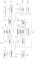
- the ophthalmologic apparatus 1 includes a fundus camera unit 2, an OCT unit 100, and an arithmetic control unit 200.
- the retinal camera unit 2 has almost the same optical system as a conventional retinal camera.
- the OCT unit 100 is provided with an optical system for acquiring an OCT image of the fundus.
- the arithmetic control unit 200 includes a computer that executes various arithmetic processes and control processes.
- the fundus camera unit 2 shown in FIG. 1 is provided with an optical system for obtaining a two-dimensional image (fundus image) representing the surface form of the fundus oculi Ef of the eye E to be examined.
- the fundus image includes an observation image and a captured image.
- the observation image is, for example, a monochrome moving image formed at a predetermined frame rate using near infrared light.
- the fundus camera unit 2 can obtain an observation image of the anterior segment Ea.
- the captured image may be, for example, a color image obtained by flashing visible light, or a monochrome still image using near infrared light or visible light as illumination light.
- the fundus camera unit 2 may be configured to be able to acquire images other than these, such as a fluorescein fluorescent image, an indocyanine green fluorescent image, a spontaneous fluorescent image, and the like.
- the fundus camera unit 2 is provided with a chin rest and a forehead for supporting the subject's face.
- the chin rest and the forehead support correspond to the support portion 440 shown in FIGS. 4A and 4B.
- reference numeral 410 denotes a drive system such as the optical system drive unit 2A and a base in which an arithmetic control circuit is stored.
- Reference numeral 420 denotes a housing provided on the base 410 and storing an optical system.
- Reference numeral 430 denotes a lens housing portion that is provided on the front surface of the housing 420 and accommodates the objective lens 22.
- the fundus camera unit 2 is provided with an illumination optical system 10 and a photographing optical system 30.
- the illumination optical system 10 irradiates the fundus oculi Ef with illumination light.
- the photographing optical system 30 guides the fundus reflection light of the illumination light to an imaging device (CCD image sensor (sometimes simply referred to as a CCD) 35, 38).
- the imaging optical system 30 guides the signal light from the OCT unit 100 to the fundus oculi Ef and guides the signal light passing through the fundus oculi Ef to the OCT unit 100.
- the observation light source 11 of the illumination optical system 10 is composed of, for example, a halogen lamp.
- the light (observation illumination light) output from the observation light source 11 is reflected by the reflection mirror 12 having a curved reflection surface, passes through the condensing lens 13, passes through the visible cut filter 14, and is converted into near infrared light. Become. Further, the observation illumination light is once converged in the vicinity of the photographing light source 15, reflected by the mirror 16, and passes through the relay lenses 17 and 18, the diaphragm 19 and the relay lens 20. Then, the observation illumination light is reflected at the peripheral portion (region around the hole portion) of the aperture mirror 21, passes through the dichroic mirror 46, and is refracted by the objective lens 22 to illuminate the fundus oculi Ef.
- An LED Light Emitting Diode
- the fundus reflection light of the observation illumination light is refracted by the objective lens 22, passes through the dichroic mirror 46, passes through the hole formed in the central region of the perforated mirror 21, passes through the dichroic mirror 55, and is a focusing lens. It is reflected by the mirror 32 via 31. Furthermore, the fundus reflection light passes through the half mirror 39A, is reflected by the dichroic mirror 33, and forms an image on the light receiving surface of the CCD image sensor 35 by the condenser lens.
- the CCD image sensor 35 detects fundus reflected light at a predetermined frame rate, for example. On the display device 3, an image (observation image) based on fundus reflection light detected by the CCD image sensor 35 is displayed. When the photographing optical system is focused on the anterior segment, an observation image of the anterior segment of the eye E is displayed.
- the photographing light source 15 is constituted by, for example, a xenon lamp.
- the light (imaging illumination light) output from the imaging light source 15 is applied to the fundus oculi Ef through the same path as the observation illumination light.
- the fundus reflection light of the imaging illumination light is guided to the dichroic mirror 33 through the same path as that of the observation illumination light, passes through the dichroic mirror 33, is reflected by the mirror 36, and is reflected by the condenser lens 37 of the CCD image sensor 38.
- An image is formed on the light receiving surface.
- On the display device 3 an image (captured image) based on fundus reflection light detected by the CCD image sensor 38 is displayed.
- the display device 3 that displays the observation image and the display device 3 that displays the captured image may be the same or different.
- an infrared captured image is displayed. It is also possible to use an LED as a photographing light source.
- the LCD (Liquid Crystal Display) 39 displays a fixation target and an eyesight measurement index.
- the fixation target is an index for fixing the eye E to be examined, and is used at the time of fundus photographing or OCT measurement.
- a part of the light output from the LCD 39 is reflected by the half mirror 39A, reflected by the mirror 32, passes through the focusing lens 31 and the dichroic mirror 55, passes through the hole of the perforated mirror 21, and reaches the dichroic.
- the light passes through the mirror 46, is refracted by the objective lens 22, and is projected onto the fundus oculi Ef.
- the fixation position of the eye E can be changed by changing the display position of the fixation target on the screen of the LCD 39.
- As the fixation position of the eye E for example, a position for acquiring an image centered on the macular portion of the fundus oculi Ef, or a position for acquiring an image centered on the optic disc as in the case of a conventional fundus camera And a position for acquiring an image centered on the fundus center between the macula and the optic disc. It is also possible to arbitrarily change the display position of the fixation target.
- the fundus camera unit 2 is provided with an alignment optical system 50 and a focus optical system 60 as in the conventional fundus camera.
- the alignment optical system 50 generates an index (alignment index) for performing alignment (alignment) of the apparatus optical system with respect to the eye E.
- the configuration for projecting the alignment index onto the eye E corresponds to an example of a “projection optical system”.
- the focus optical system 60 generates an index (split index) for focusing on the fundus oculi Ef.
- the light (alignment light) output from the LED 51 of the alignment optical system 50 is reflected by the dichroic mirror 55 via the apertures 52 and 53 and the relay lens 54, passes through the hole of the perforated mirror 21, and reaches the dichroic mirror 46. And is projected onto the cornea of the eye E by the objective lens 22.
- the corneal reflection light of the alignment light passes through the objective lens 22, the dichroic mirror 46 and the hole, part of which passes through the dichroic mirror 55, passes through the focusing lens 31, is reflected by the mirror 32, and is half mirror
- the light passes through 39A, is reflected by the dichroic mirror 33, and is projected onto the light receiving surface of the CCD image sensor 35 by the condenser lens.
- the light reception image (alignment index) by the CCD image sensor 35 is displayed on the display device 3 together with the observation image.
- the user performs alignment by performing the same operation as that of a conventional fundus camera. Further, the arithmetic control unit 200 may perform alignment by analyzing the position of the alignment index and moving the optical system (auto-alignment function).
- auto-alignment can be performed using an anterior segment camera 300 described later, it is not essential that auto-alignment using an alignment index is possible.
- the auto-alignment using the alignment index can be performed when the auto-alignment using the anterior segment camera 300 is not successful, or the auto-alignment using the anterior segment camera 300 and the alignment index are used. It is also possible to configure so that auto alignment can be used selectively.
- the reflecting surface of the reflecting rod 67 is obliquely provided on the optical path of the illumination optical system 10.
- the light (focus light) output from the LED 61 of the focus optical system 60 passes through the relay lens 62, is separated into two light beams by the split indicator plate 63, passes through the two-hole aperture 64, and is reflected by the mirror 65, The light is focused on the reflecting surface of the reflecting bar 67 by the condenser lens 66 and reflected. Further, the focus light passes through the relay lens 20, is reflected by the perforated mirror 21, passes through the dichroic mirror 46, is refracted by the objective lens 22, and is projected onto the fundus oculi Ef.
- the fundus reflection light of the focus light is detected by the CCD image sensor 35 through the same path as the corneal reflection light of the alignment light.
- a light reception image (split index) by the CCD image sensor 35 is displayed on the display device 3 together with the observation image.
- the arithmetic and control unit 200 analyzes the position of the split index and moves the focusing lens 31 and the focus optical system 60 to perform focusing as in the conventional case (autofocus function). Alternatively, focusing may be performed manually while visually checking the split indicator.
- the dichroic mirror 46 branches the optical path for OCT measurement from the optical path for fundus imaging.
- the dichroic mirror 46 reflects light in a wavelength band used for OCT measurement and transmits light for fundus photographing.
- a collimator lens unit 40, an optical path length changing unit 41, a galvano scanner 42, a focusing lens 43, a mirror 44, and a relay lens 45 are provided in this order from the OCT unit 100 side. It has been.
- the optical path length changing unit 41 is movable in the direction of the arrow shown in FIG. 1, and changes the optical path length of the optical path for OCT measurement. This change in the optical path length is used for correcting the optical path length according to the axial length of the eye E or adjusting the interference state.
- the optical path length changing unit 41 includes, for example, a corner cube and a mechanism for moving the corner cube.
- the galvano scanner 42 changes the traveling direction of light (signal light LS) passing through the optical path for OCT measurement. Thereby, the fundus oculi Ef can be scanned with the signal light LS.
- the galvano scanner 42 includes, for example, a galvano mirror that scans the signal light LS in the x direction, a galvano mirror that scans in the y direction, and a mechanism that drives these independently. Thereby, the signal light LS can be scanned in an arbitrary direction on the xy plane.
- the fundus camera unit 2 is provided with an anterior eye camera 300.
- the anterior segment camera 300 images the anterior segment Ea substantially simultaneously from different directions.
- two cameras are provided on the subject-side surface of the fundus camera unit 2 (see anterior eye cameras 300A and 300B shown in FIG. 4A).
- the anterior eye cameras 300A and 300B are provided at positions deviated from the optical path of the illumination optical system 10 and the optical path of the imaging optical system 30, respectively.
- the two anterior eye cameras 300A and 300B may be collectively represented by reference numeral 300.
- two anterior eye cameras 300A and 300B are provided, but the number of anterior eye cameras in the present invention is an arbitrary number of 2 or more. However, in consideration of the arithmetic processing described later, a configuration that can photograph the anterior segment substantially simultaneously from two different directions is sufficient.
- the anterior segment camera 300 is provided separately from the illumination optical system 10 and the imaging optical system 30, but at least the imaging optical system 30 can be used to perform similar anterior segment imaging. . That is, one of the two or more anterior segment cameras may be carried by a configuration including the imaging optical system 30.
- this embodiment should just be comprised so that imaging
- substantially simultaneously indicates that a photographing timing shift that allows negligible eye movement is allowed in photographing with two or more anterior segment cameras. Thereby, an image when the eye E is substantially at the same position (orientation) can be acquired by two or more anterior segment cameras.
- shooting with two or more anterior eye cameras may be moving image shooting or still image shooting
- the case of moving image shooting will be described in detail.
- the above-described substantially simultaneous anterior ocular shooting can be realized by controlling the shooting start timing to match or by controlling the frame rate and shooting timing of each frame.
- this can be realized by controlling to match the shooting timing.
- the OCT unit 100 is provided with an optical system for acquiring an OCT image of the fundus oculi Ef.
- This optical system has the same configuration as a conventional spectral domain type OCT apparatus. That is, this optical system divides low-coherence light into reference light and signal light, and generates interference light by causing interference between the signal light passing through the fundus oculi Ef and the reference light passing through the reference optical path. It is configured to detect spectral components. This detection result (detection signal) is sent to the arithmetic control unit 200.
- a wavelength swept light source is provided instead of a light source that outputs a low coherence light source, and an optical member that spectrally decomposes interference light is not provided.
- a known technique corresponding to the type of OCT can be arbitrarily applied.
- the light source unit 101 outputs a broadband low-coherence light L0.
- the low coherence light L0 includes, for example, a near-infrared wavelength band (about 800 nm to 900 nm) and has a temporal coherence length of about several tens of micrometers. Note that near-infrared light having a wavelength band invisible to the human eye, for example, a center wavelength of about 1040 to 1060 nm, may be used as the low-coherence light L0.
- the light source unit 101 includes a super luminescent diode (Super Luminescent Diode: SLD), an LED, and an optical output device such as an SOA (Semiconductor Optical Amplifier).
- SLD Super Luminescent Diode
- LED an LED
- SOA semiconductor Optical Amplifier
- the low coherence light L0 output from the light source unit 101 is guided to the fiber coupler 103 by the optical fiber 102, and is divided into the signal light LS and the reference light LR.
- the reference light LR is guided by the optical fiber 104 and reaches an optical attenuator (attenuator) 105.
- the optical attenuator 105 automatically adjusts the amount of the reference light LR guided to the optical fiber 104 under the control of the arithmetic control unit 200 using a known technique.
- the reference light LR whose light amount has been adjusted by the optical attenuator 105 is guided by the optical fiber 104 and reaches the polarization adjuster (polarization controller) 106.
- the polarization adjuster 106 is, for example, a device that adjusts the polarization state of the reference light LR guided in the optical fiber 104 by applying a stress from the outside to the optical fiber 104 in a loop shape.
- the configuration of the polarization adjuster 106 is not limited to this, and any known technique can be used.
- the reference light LR whose polarization state is adjusted by the polarization adjuster 106 reaches the fiber coupler 109.
- the signal light LS generated by the fiber coupler 103 is guided by the optical fiber 107 and converted into a parallel light beam by the collimator lens unit 40. Further, the signal light LS reaches the dichroic mirror 46 via the optical path length changing unit 41, the galvano scanner 42, the focusing lens 43, the mirror 44, and the relay lens 45. The signal light LS is reflected by the dichroic mirror 46, is refracted by the objective lens 22, and is applied to the fundus oculi Ef. The signal light LS is scattered (including reflection) at various depth positions of the fundus oculi Ef. The backscattered light of the signal light LS from the fundus oculi Ef travels in the same direction as the forward path in the reverse direction, is guided to the fiber coupler 103, and reaches the fiber coupler 109 via the optical fiber 108.
- the fiber coupler 109 causes the backscattered light of the signal light LS and the reference light LR that has passed through the optical fiber 104 to interfere with each other.
- the interference light LC generated thereby is guided by the optical fiber 110 and emitted from the emission end 111. Further, the interference light LC is converted into a parallel light beam by the collimator lens 112, dispersed (spectral decomposition) by the diffraction grating 113, condensed by the condenser lens 114, and projected onto the light receiving surface of the CCD image sensor 115.
- the diffraction grating 113 shown in FIG. 2 is a transmission type, other types of spectroscopic elements such as a reflection type diffraction grating may be used.
- the CCD image sensor 115 is a line sensor, for example, and detects each spectral component of the split interference light LC and converts it into electric charges.
- the CCD image sensor 115 accumulates this electric charge, generates a detection signal, and sends it to the arithmetic control unit 200.
- a Michelson type interferometer is used, but any type of interferometer such as a Mach-Zehnder type can be appropriately used.
- any type of interferometer such as a Mach-Zehnder type can be appropriately used.
- another form of image sensor for example, a CMOS (Complementary Metal Oxide Semiconductor) image sensor or the like can be used.
- CMOS Complementary Metal Oxide Semiconductor
- the configuration of the arithmetic control unit 200 will be described.
- the arithmetic control unit 200 analyzes the detection signal input from the CCD image sensor 115 and forms an OCT image of the fundus oculi Ef.
- the arithmetic processing for this is the same as that of a conventional spectral domain type OCT apparatus.
- the arithmetic control unit 200 controls each part of the fundus camera unit 2, the display device 3, and the OCT unit 100. For example, the arithmetic control unit 200 displays an OCT image of the fundus oculi Ef on the display device 3.
- the arithmetic control unit 200 controls the operation of the observation light source 11, the imaging light source 15 and the LEDs 51 and 61, the operation control of the LCD 39, the movement control of the focusing lenses 31 and 43, and the reflector 67. Movement control, movement control of the focus optical system 60, movement control of the optical path length changing unit 41, operation control of the galvano scanner 42, operation control of the anterior eye camera 300, and the like are performed.
- the arithmetic control unit 200 performs operation control of the light source unit 101, operation control of the optical attenuator 105, operation control of the polarization adjuster 106, operation control of the CCD image sensor 115, and the like.
- the arithmetic control unit 200 includes, for example, a microprocessor, a RAM, a ROM, a hard disk drive, a communication interface, and the like, as in a conventional computer.
- a computer program for controlling the ophthalmologic apparatus 1 is stored in a storage device such as a hard disk drive.
- the arithmetic control unit 200 may include various circuit boards, for example, a circuit board for forming an OCT image.
- the arithmetic control unit 200 may include an operation device (input device) such as a keyboard and a mouse, and a display device such as an LCD.
- the fundus camera unit 2, the display device 3, the OCT unit 100, and the calculation control unit 200 may be configured integrally (that is, in a single housing) or separated into two or more cases. It may be.
- Control system The configuration of the control system of the ophthalmologic apparatus 1 will be described with reference to FIG.
- the control system of the ophthalmologic apparatus 1 is configured around the control unit 210.
- the control unit 210 includes, for example, the aforementioned microprocessor, RAM, ROM, hard disk drive, communication interface, and the like.
- the control unit 210 includes a main control unit 211, a storage unit 212, and an optical system position acquisition unit 213.
- the main control unit 211 performs the various operation controls described above.
- the movement control of the focusing lens 31 is to move the focusing lens 31 in the optical axis direction by controlling a focusing drive unit (not shown). Thereby, the focus position of the photographic optical system 30 is changed.
- the main control unit 211 can control the optical system driving unit 2A to move the optical system provided in the fundus camera unit 2 three-dimensionally.
- tracking refers to moving the apparatus optical system in accordance with the eye movement of the eye E. Tracking is performed, for example, at a later stage than alignment (in some cases, focusing is also performed in advance). Tracking is a function that maintains a suitable positional relationship in alignment (and focus) by causing the position of the apparatus optical system to follow the eye movement.
- the optical system drive unit 2A of this embodiment moves an optical system mounted on the fundus camera unit 2, but the optical system and the OCT unit 100 mounted on the fundus camera unit 2 by the optical system drive unit 2A. It may be configured to move the optical system mounted on the.
- the optical system drive unit 2A is an example of a “drive unit”.
- the anterior eye camera 300 of this embodiment is provided in the housing of the fundus camera unit 2, the anterior eye camera 300 can be moved by controlling the optical system driving part 2A. Further, it is possible to provide a photographing moving unit that can independently move two or more anterior eye camera 300.
- the imaging moving unit may include a drive mechanism (an actuator, a power transmission mechanism, etc.) provided for each anterior eye camera 300.
- the imaging moving unit is configured to move two or more anterior eye cameras 300 by transmitting power generated by a single actuator by a power transmission mechanism provided for each anterior eye camera 300. May be.
- the main control unit 211 performs a process of writing data to the storage unit 212 and a process of reading data from the storage unit 212.
- the storage unit 212 stores various data. Examples of the data stored in the storage unit 212 include OCT image image data, fundus image data, and examined eye information.
- the eye information includes information about the subject such as patient ID and name, and information about the eye such as left / right eye identification information.
- the storage unit 212 stores various programs and data for operating the ophthalmologic apparatus 1.
- correction information 212a is stored in advance.
- the correction information 212a is information acquired based on the optical characteristics of the eyeball, and is used for correcting the position of the eye to be examined in the optical axis direction of the inspection optical system.
- the inspection optical system is an optical system that is used for an inspection performed by the ophthalmologic apparatus 1 (photographing of an eye to be examined, OCT measurement, etc.).
- the optical system provided in the fundus camera unit 2 or the OCT unit 100 corresponds to the inspection optical system.
- the optical axis of the inspection optical system in this embodiment is the optical axis of the photographing optical system 30.
- the optical axis of the imaging optical system 30 is the same as the optical axis of the illumination optical system 100 and the optical system for OCT measurement.
- the ophthalmologic apparatus 1 image photographs the anterior eye part Ea substantially simultaneously from a different direction, analyzes the two captured images obtained by that, and determines the three-dimensional position of the eye E to be examined. get.
- the correction information 212a is used for correcting this three-dimensional position.
- the anterior eye portion Ea of the eye E is imaged by the two anterior eye cameras 300A and 300B, and the captured images are analyzed to determine the three-dimensional position of the eye E.
- the three-dimensional position of the feature point of the anterior segment Ea is obtained.
- the cornea is transparent, so that it is inappropriate as the feature point. Therefore, the feature point is set to a black eye (pupil, iris).
- the pupil and the iris are tissues existing in the eye, the position of the feature point obtained from the photographed image changes depending on the refractive power of the anterior eye part.
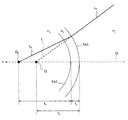
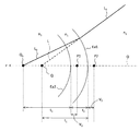
- the refractive power of the anterior eye part causes displacement of feature points in the optical axis direction of the inspection optical system. This displacement corresponds to the difference between the position Q 0 and the position Q shown in FIG.
- a symbol O indicates an optical axis of an inspection optical system (such as the photographing optical system 30). Although not shown, the inspection optical system is arranged on the right side of FIG.
- Symbol Ea1 indicates the front surface (corneal front surface) of the cornea Ea
- symbol Ea2 indicates the rear surface (corneal rear surface) of the cornea Ea.
- the radius of curvature of the anterior corneal surface Ea1 illustrated in r 1 illustrating the radius of curvature of the posterior surface of the cornea Ea2 in r 2.
- the feature point is assumed to be the pupil center, that is, the center (vertex) of the front surface of the crystalline lens.
- Symbol Q 0 indicates the actual position of the pupil center
- symbol Q indicates the apparent position of the pupil center.
- n 1 indicates the refractive index of air
- symbol n 2 indicates the refractive index of the cornea
- symbol n 3 indicates the refractive index of the anterior chamber (aqueous humor).
- WD 0 indicates a general working distance (working distance) indicating the distance from the top surface of the objective lens 22 to the front surface of the cornea.
- a general working distance WD 0 is set to 34.8 mm, for example.
- To obtain the distance WD it is necessary to calculate the distance t 1.
- an example of calculating the distance t 1 will be described. For simplification of explanation, an example by paraxial approximation calculation is shown.
- the focal length of the anterior corneal surface Ea1 and f 1 the focal length of the posterior surface of the cornea Ea2 and f 2, a focal length of the cornea Ea and f 3.
- model eye values are applied.
- the type of model eye is arbitrary (Gulstrand model eye, Navarro model eye, LeGrand model eye, etc.).
- the refractive index of air n 1 1;
- the refractive index of aqueous humor n 3 1.336;
- the focal length of the cornea Ea f 3 31.03 mm;
- the thickness of the cornea Ea t 2 0.5 mm;
- the distance t 3 3.1 mm between the corneal posterior surface Ea2 and the actual position Q 0 of the pupil center.
- the above example is based on paraxial approximation calculation, but it is also possible to calculate the distance t1 and the distance WD by simulation (real ray tracing or the like).
- the value of the model eye is applied, but it is possible to use the measured value of the eye E for any of the parameters.
- the measured value of the eye E for example, by analyzing an OCT image of the anterior segment Ea, the thickness of the cornea Ea (distance t 2 ), the depth of aqueous humor (distance t 3 ), and the distance (distance t 2 + t) between the front surface of the cornea Ea1 and the front surface of the lens. 3 )
- the curvature radius r 1 of the corneal front surface Ea1, the curvature radius r 2 of the corneal rear surface Ea2, and the like can be acquired and applied.
- the refractive power and curvature radius of the cornea Ea acquired by the refractometer or the keratometer can be applied. These measured values are acquired in advance and stored in the storage unit 212. Such prior measurement may be performed by the ophthalmologic apparatus 1 or may be performed by another ophthalmologic apparatus.
- the front the refractive power of the eye portion Ea is dominant refractive power of the anterior corneal surface Ea1, may perform an operation similar to the above on the basis of the curvature radius r 1 of the anterior corneal surface Ea1.
- the correction amount (displacement) of the three-dimensional position of the feature point of the anterior segment Ea can be obtained in advance, and this can be applied to any eye to be examined. can do.
- the displacement value itself can be stored as correction information 212a.
- the measurement value (optical characteristic information) of the optical characteristic of the anterior eye part of the eye E acquired in advance is stored as the correction information 212a.
- the correction information 212a also stores a standard value of the optical characteristics of the anterior segment shown in the model eye or the like.
- a position correction unit 232 described later calculates a displacement ⁇ t due to the influence of the anterior segment Ea of the eye E based on correction information 212a including optical characteristic information and standard values. This calculation process is executed based on the above algorithm or simulation.
- aberration information is stored in the storage unit 212 in advance.
- information on distortion aberration generated in the captured image due to the influence of the optical system mounted on each anterior segment camera 300 is recorded.
- the optical system mounted on the anterior segment camera 300 includes an optical element that generates distortion, such as a lens.
- the aberration information can be said to be a parameter obtained by quantifying the distortion that these optical elements give to the photographed image.
- the operator prepares a predetermined reference point.
- the reference point is an imaging target used for detecting distortion.
- the operator performs multiple shootings while changing the relative position between the reference point and the anterior eye camera 300. Thereby, a plurality of captured images of the reference point captured from different directions are obtained.
- the operator generates aberration information of the anterior eye camera 300 by analyzing a plurality of acquired captured images with a computer.
- the computer that performs this analysis processing may be the image processing unit 230 or any other computer (an inspection computer before product shipment, a maintenance computer, etc.).
- the analysis process for generating aberration information includes, for example, the following steps: An extraction step of extracting an image region corresponding to the reference point from each captured image; A distribution state calculation step of calculating a distribution state (coordinates) of an image area corresponding to a reference point in each captured image; A distortion aberration calculating step of calculating a parameter representing distortion based on the obtained distribution state; A correction coefficient calculation step of calculating a coefficient for correcting distortion based on the obtained parameter.
- the parameters related to the distortion aberration given to the image by the optical system include principal point distance, principal point position (vertical direction, horizontal direction), lens distortion (radial direction, tangential direction), and the like.
- the aberration information is configured as information (for example, table information) in which the identification information of each anterior segment camera 300 is associated with the correction coefficient corresponding thereto.
- the aberration information generated in this way is stored in the storage unit 212 by the main control unit 211. Such generation of aberration information and correction of aberration based on the aberration information are called camera calibration.
- the optical system position acquisition unit 213 acquires the current position of the inspection optical system mounted on the ophthalmologic apparatus 1.
- the inspection optical system is an optical system used to optically inspect the eye E.
- the inspection optical system in the ophthalmologic apparatus 1 (a combination machine of a fundus camera and an OCT apparatus) of this embodiment is an optical system for obtaining an image of the eye to be examined.
- the optical system position acquisition unit 213 receives, for example, information indicating the content of movement control of the optical system driving unit 2A by the main control unit 211, and acquires the current position of the inspection optical system moved by the optical system driving unit 2A. To do. A specific example of this process will be described.
- the main control unit 211 controls the optical system driving unit 2A at a predetermined timing (when the apparatus is activated, when patient information is input, etc.) to move the examination optical system to a predetermined initial position. Thereafter, each time the optical system driving unit 2A is controlled, the main control unit 211 records the control contents. Thereby, a history of control contents is obtained.
- the optical system position acquisition unit 213 acquires the control content up to the present with reference to this history, and obtains the current position of the inspection optical system based on the control content.
- the control content is transmitted to the optical system position acquisition unit 213, and each time the optical system position acquisition unit 213 receives the control content, the inspection optical system is transmitted.
- the current position may be obtained sequentially.
- a position sensor that detects the position of the inspection optical system may be provided in the optical system position acquisition unit 213.
- the main control unit 211 determines the acquired current position and the eye E to be examined obtained by the analysis unit 231 described later.
- the inspection optical system can be moved to the optical system driving unit 2A based on the three-dimensional position.
- the main control unit 211 recognizes the current position of the inspection optical system based on the acquisition result obtained by the optical system position acquisition unit 213, and recognizes the three-dimensional position of the eye E based on the analysis result obtained by the analysis unit 231.
- the main control unit 211 changes the position of the inspection optical system from the current position so that the position of the inspection optical system with respect to the three-dimensional position of the eye E has a predetermined positional relationship.
- This predetermined positional relationship is such that the positions in the x direction and the y direction coincide with each other and the distance in the z direction becomes a predetermined working distance.
- the image forming unit 220 forms tomographic image data of the fundus oculi Ef based on the detection signal from the CCD image sensor 115.
- This process includes processes such as noise removal (noise reduction), filter processing, FFT (Fast Fourier Transform), and the like, as in the conventional spectral domain type optical coherence tomography.
- the image forming unit 220 executes a known process corresponding to the type.
- the image forming unit 220 includes, for example, the circuit board described above. In this specification, “image data” and “image” based thereon may be identified.
- the image processing unit 230 performs various types of image processing and analysis processing on the image formed by the image forming unit 220. For example, the image processing unit 230 executes various correction processes such as image brightness correction and dispersion correction. The image processing unit 230 performs various types of image processing and analysis processing on the image (fundus image, anterior eye image, etc.) obtained by the fundus camera unit 2.
- the image processing unit 230 executes known image processing such as interpolation processing for interpolating pixels between tomographic images to form image data of a three-dimensional image of the fundus oculi Ef.
- image data of a three-dimensional image means image data in which pixel positions are defined by a three-dimensional coordinate system.
- image data of a three-dimensional image there is image data composed of voxels arranged three-dimensionally. This image data is called volume data or voxel data.
- the image processing unit 230 When displaying an image based on volume data, the image processing unit 230 performs a rendering process (such as volume rendering or MIP (Maximum Intensity Projection)) on the volume data, and views the image from a specific line-of-sight direction.
- Image data of a pseudo three-dimensional image is formed.
- the pseudo three-dimensional image is displayed on the display unit 240A.
- stack data of a plurality of tomographic images is image data of a three-dimensional image.
- the stack data is image data obtained by three-dimensionally arranging a plurality of tomographic images obtained along a plurality of scanning lines based on the positional relationship of the scanning lines. That is, stack data is image data obtained by expressing a plurality of tomographic images originally defined by individual two-dimensional coordinate systems by one three-dimensional coordinate system (that is, by embedding them in one three-dimensional space). is there.
- the image processing unit 230 is provided with an analysis unit 231 and a position correction unit 232.
- the analysis unit 231 obtains the three-dimensional position of the eye E by analyzing two or more captured images obtained substantially simultaneously by the two or more anterior segment cameras 300.
- the analysis unit 231 includes an image correction unit 2311, a feature point specifying unit 2312, and a three-dimensional position calculation unit 2313.
- the image correction unit 2311 corrects the distortion of each captured image obtained by the anterior eye camera 300 based on the aberration information stored in the storage unit 212. This process is executed by, for example, a known image processing technique based on a correction coefficient for correcting distortion. Note that the aberration information and the image correction unit 2311 may not be provided when the distortion aberration given to the captured image by the optical system of the anterior segment camera 300 is sufficiently small.
- the feature point specifying unit 2312 analyzes each captured image (the distortion of which has been corrected by the image correction unit 2311), thereby obtaining an image position (referred to as a feature position) corresponding to a predetermined feature point of the anterior segment Ea. Identify.
- a feature position an image position corresponding to a predetermined feature point of the anterior segment Ea. Identify.
- the pupil center is used as the feature point.
- the feature point specifying unit 2312 specifies an image region (pupil region) corresponding to the pupil of the eye E based on the distribution of pixel values (such as luminance values) of the captured image.
- the pupil area can be specified by searching for the low brightness image area.
- the pupil region may be specified in consideration of the shape of the pupil. That is, the pupil region can be specified by searching for a substantially circular and low luminance image region.
- the feature point specifying unit 2312 specifies the center position of the specified pupil region. Since the pupil is substantially circular as described above, the contour of the pupil region can be specified, the center position of this contour (approximate circle or approximate ellipse) can be specified, and this can be used as the pupil center. Further, the center of gravity of the pupil region may be obtained, and the position of the center of gravity may be used as the center of the pupil.
- the feature position can be specified based on the distribution of pixel values of the captured image in the same manner as described above.
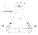
- the three-dimensional position calculation unit 2313 calculates the feature points of the eye E based on the positions of the two or more anterior eye camera 300 and the feature positions in the two or more captured images specified by the feature point specifying unit 2312. A three-dimensional position is calculated. This process will be described with reference to FIGS. 6A and 6B.
- FIG. 6A is a top view showing the positional relationship between the eye E and the anterior eye cameras 300A and 300B.
- FIG. 6B is a side view showing the positional relationship between the eye E and the anterior eye cameras 300A and 300B.
- the distance (baseline length) between the two anterior eye cameras 300A and 300B is represented by “B”.
- a distance (imaging distance) between the baselines of the two anterior eye cameras 300A and 300B and the feature point P of the eye E is represented by “H”.
- a distance (screen distance) between each anterior eye camera 300A and 300B and its screen plane is represented by “f”.
- the resolution of the captured image by the anterior segment cameras 300A and 300B is expressed by the following equation.
- ⁇ p represents pixel resolution.
- the three-dimensional position calculation unit 2313 compares the positions (known) of the two anterior eye cameras 300A and 300B and the feature position corresponding to the feature point P in the two captured images in FIGS. 6A and 6B. By applying a known trigonometric method in consideration of the arrangement relationship shown, the three-dimensional position of the feature point P, that is, the three-dimensional position of the eye E to be examined is calculated.
- the three-dimensional position of the eye E calculated by the three-dimensional position calculation unit 2313 is sent to the control unit 210. Based on the calculation result of the three-dimensional position, the control unit 210 adjusts the optical axis of the inspection optical system to the axis of the eye E, and the distance of the inspection optical system with respect to the eye E is a predetermined operation.
- the optical system driving unit 2A is controlled so as to be a distance.
- the working distance is a predetermined value called a working distance, and means a distance between the eye E to be inspected and the inspection optical system at the time of inspection using the inspection optical system.
- the anterior eye camera 300 shoots a moving image of the anterior eye part Ea from different directions in parallel, for example, the following processes (1) and (2) are performed to test the movement of the eye E to be examined. It is possible to perform tracking of the optical system.
- the analysis unit 231 sequentially obtains the three-dimensional position of the eye E by sequentially analyzing two or more frames obtained substantially simultaneously in moving image shooting by the two or more anterior segment cameras 300. .
- the control unit 210 sequentially controls the optical system driving unit 2A based on the three-dimensional position of the eye E to be sequentially obtained by the analysis unit 231, thereby changing the position of the inspection optical system to the movement of the eye E. To follow.
- the position correction unit 232 corrects the three-dimensional position of the eye E (pupil center) acquired by the three-dimensional position calculation unit 2313 based on the correction information 212 a stored in the storage unit 212.
- the position correction unit 232 changes the three-dimensional position of the pupil center by a distance corresponding to the displacement ⁇ t. In this process, the coordinates of the three-dimensional position of the pupil center are moved by ⁇ t in the + z direction.
- the position correction unit 232 calculates the displacement ⁇ t based on the optical characteristic information and the standard value included in the correction information 212a. Further, the position correction unit 232 corrects the three-dimensional position of the pupil center acquired by the three-dimensional position calculation unit 2313 based on the calculated displacement ⁇ t. This correction process is the same as when the displacement ⁇ t itself is stored in the correction information 212a.
- the image processing unit 230 that functions as described above includes, for example, the aforementioned microprocessor, RAM, ROM, hard disk drive, circuit board, and the like.
- a storage device such as a hard disk drive, a computer program for causing the microprocessor to execute the above functions is stored in advance.
- the user interface 240 includes a display unit 240A and an operation unit 240B.
- the display unit 240A includes the display device of the arithmetic control unit 200 and the display device 3 described above.
- the operation unit 240B includes the operation device of the arithmetic control unit 200 described above.
- the operation unit 240B may include various buttons and keys provided on the housing of the ophthalmologic apparatus 1 or outside.
- the operation unit 240B may include a joystick, an operation panel, or the like provided on the housing.
- the display unit 240 ⁇ / b> A may include various display devices such as a touch panel provided on the housing of the fundus camera unit 2.
- the display unit 240A and the operation unit 240B do not need to be configured as individual devices.
- a device in which a display function and an operation function are integrated such as a touch panel
- the operation unit 240B includes the touch panel and a computer program.
- the operation content for the operation unit 240B is input to the control unit 210 as an electrical signal. Further, operations and information input may be performed using a graphical user interface (GUI) displayed on the display unit 240A and the operation unit 240B.
- GUI graphical user interface
- Patient information includes patient ID, patient name, and the like.
- Imaging type (S2: Selection of shooting type)
- Items of this imaging type include an imaging region (optic nerve head, macular, both, etc.), imaging eye (left eye, right eye, both eyes), image capturing pattern (fundus image only, OCT image only, both), OCT scan. There are patterns (line scan, cross scan, radial scan, circle scan, three-dimensional scan, etc.).
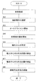
- This start instruction may be automatically issued by the control unit 210 in response to the selection of the shooting type shown in step 2, or may be manually performed by the user using the operation unit 240B.
- the control unit 210 starts imaging of the anterior segment Ea by the anterior segment cameras 300A and 300B.
- This shooting is moving image shooting in which the anterior segment Ea is a shooting target.
- Each anterior eye camera 300A and 300B shoots a moving image at a predetermined frame rate.
- the imaging timings of the anterior eye cameras 300A and 300B may be synchronized by the control unit 210.
- Each anterior eye camera 300A and 300B sequentially sends the acquired frames to the control unit 210 in real time.
- the controller 210 associates the frames obtained by both anterior eye cameras 300A and 300B according to the photographing timing.
- control unit 210 associates frames acquired substantially simultaneously by both anterior eye cameras 300A and 300B. This association is executed, for example, based on the above-described synchronization control or based on the input timing of frames from the anterior eye cameras 300A and 300B.
- the control unit 210 sends a pair of associated frames to the analysis unit 231.
- the image correction unit 2311 corrects the distortion of each frame sent from the control unit 210 based on the aberration information stored in the storage unit 212. This correction processing is executed as described above. The pair of frames whose distortion has been corrected is sent to the feature point specifying unit 2312.
- the feature point specifying unit 2312 analyzes the pair of frames sent from the image correcting unit 2311, thereby specifying the feature position in the frame corresponding to the pupil center of the anterior segment Ea.
- the anterior eye camera 300 can be moved again in the direction away from the support part 440 and / or the outside of the support part 440, and imaging of the anterior eye part Ea can be performed again. Further, even when the image corresponding to the anterior segment Ea is located at the end of the frame, the anterior segment camera 300 can be moved so that the anterior segment Ea is arranged in the central region of the frame. It is.
- the three-dimensional position calculation unit 2313 calculates the three-dimensional position of the pupil center of the eye E based on the positions of the anterior eye cameras 300A and 300B and the image position (characteristic position) of the pupil center specified in step 5. calculate. This process is executed as described above.
- the coordinates of the calculated three-dimensional position in the xyz coordinate system are (x, y, z).
- the position correction unit 232 corrects the three-dimensional position of the pupil center calculated in step 6 based on the correction information 212a. This process is executed as described above. In the example shown in FIG. 5, by this correction process, the coordinates (x, y, z) of the pupil center calculated in step 6 are changed to (x, y, z + ⁇ t).
- the control unit 210 moves the inspection optical system by controlling the optical system driving unit 2A based on the three-dimensional position of the pupil center corrected in Step 7.
- the optical axis of the inspection optical system is matched with the axis of the eye E, and the distance of the inspection optical system with respect to the eye E is matched with a predetermined working distance.
- WD 0 is a general working distance indicating the distance from the top surface of the objective lens 22 to the front surface of the cornea Ea1, and is a predetermined value.
- the inspection optical system is aligned in the z direction so as to match the apparent position Q of the pupil center shown in FIG.
- the correction processing in step S7 it is possible to realize the alignment of the z-direction of the examination optical system relative to the position (i.e. true position) Q 0 in a real space of the pupil center.
- the ophthalmologic apparatus 1 includes an examination optical system, an optical system drive unit 2A (drive unit), an anterior eye camera 300 (two or more imaging units), an analysis unit 231, a storage unit 212, and a position correction unit 232. (Correction unit) and a control unit 210 (particularly the main control unit 211).
- the inspection optical system is an optical system for inspecting the eye E.
- the optical system driving unit 2A moves the inspection optical system.
- the anterior segment camera 300 images the anterior segment Ea of the eye E from substantially different directions at the same time.
- the analysis unit 231 analyzes a captured image obtained substantially simultaneously by the anterior eye camera 300 and acquires a three-dimensional position of the eye E to be examined.
- the storage unit 212 stores correction information 212a in advance.
- the correction information 212a is acquired based on the optical characteristics of the eyeball, and is used to correct the position of the eye E in the optical axis direction of the inspection optical system.
- the position correction unit 232 corrects the three-dimensional position of the eye E acquired by the analysis unit 231 based on the correction information 212a.
- the control unit 210 controls the optical system driving unit 2A based on the corrected three-dimensional position to move the inspection optical system.
- the eye to be examined is based on two or more captured images of the anterior segment Ea. 3 three-dimensional positions (xyz coordinates) can be acquired. Therefore, conventional problems such as a decrease in inspection accuracy and a decrease in reproducibility due to an error between the alignment in the xy direction and the alignment in the z direction are solved.
- the three-dimensional position of the eye E thus obtained can be corrected based on the optical characteristics of the eyeball.
- the analyzing unit 231 includes, for example, a feature point specifying unit 2312 and a three-dimensional position calculating unit 2313.
- the feature point specifying unit 2312 analyzes the captured image acquired by the anterior eye camera 300 and specifies an image position corresponding to a feature point of the pupil or iris.
- the three-dimensional position calculation unit 2313 calculates the three-dimensional position of the feature point based on the position of the anterior eye camera 300 and the image position specified by the feature point specifying unit 2312. The three-dimensional position of this feature point is used as the three-dimensional position of the eye E.
- the correction information 212a may include a displacement ⁇ t in the optical axis direction (z direction) of the image position of the feature point due to the refractive power of the anterior segment Ea.
- the position correction unit 232 changes the three-dimensional position of the feature point calculated by the three-dimensional position calculation unit 2313 by a distance corresponding to the displacement ⁇ t.
- the controller 210 moves the inspection optical system based on the three-dimensional position that has been subjected to such correction.
- the correction information 212a may include optical characteristic information indicating a measured value of the optical characteristic of the anterior segment Ea of the eye E to be examined.
- the position correction unit 232 calculates the displacement ⁇ t of the image position due to the refractive power of the anterior segment Ea of the eye E based on this optical characteristic information.
- the position correction unit 232 changes the three-dimensional position of the feature point calculated by the three-dimensional position calculation unit 2313 based on the displacement ⁇ t.
- the controller 210 moves the inspection optical system based on the three-dimensional position that has been subjected to such correction. According to this example, it is possible to perform alignment with high accuracy according to each eye E to be examined.
- the correction information 212a also stores a standard value of the optical characteristics of the anterior segment necessary for calculating the displacement ⁇ t.
- the refractive power of the anterior segment Ea indicates the refractive power of the tissue from the front of the cornea to the iris (pupil), that is, the refractive power of the cornea and the refractive power of the anterior chamber (aqueous humor).
- the displacement ⁇ t may be a value ⁇ t substantially calculated by the following equation.
- N 1 / t 1 (n 3 / f 3 ) ⁇ [n 3 / (t 2 + t 3 )] (1)
- ⁇ t t 2 + t 3 ⁇ t 1 (2)
- n 1 represents the refractive index of air
- n 3 represents the refractive index of the aqueous humor
- f 3 represents the focal length of the cornea
- t 2 represents the thickness of the cornea
- t 3 represents the posterior cornea and pupil. Indicates the distance to the center.
- substantially means not only the case where these mathematical expressions are actually used, but also the case where processing (for example, real ray tracing) that can be used as an alternative to these mathematical expressions is used.
- the refractive index n 1 of the air at least for the refractive index n 1 of the air, the refractive index n 3 and the focal length f 3 of the cornea of aqueous humor, it is possible to use the values shown in the eye model. When these values are measured in advance, the measured values can be stored as optical characteristic information (correction information 212a).
- the refractive index n 1 of air, the refractive index n 3 of aqueous humor, the focal length f 3 of the cornea, the thickness t 2 of the cornea, and the distance t 3 are It is possible to use the values shown in the gull strand model eye.
- the measurement value (optical characteristic information) of the eye E When the measurement value (optical characteristic information) of the eye E is applied, the measurement value of the cornea thickness t 2 and / or the distance t 3 of the eye E can be used.
- the focal length f 3 of the cornea When calculating the focal length f 3 of the cornea, the refractive index n 1 of the air, the refractive index n 2 of the cornea, the refractive index n 3 of the aqueous humor, cornea thickness t 2, the anterior corneal surface curvature radius r 1 and the corneal posterior surface it is possible to calculate the focal length f 3 of the cornea based on the radius of curvature r 2.
- the algorithm is based on the expression of the refractive power D 3 of formula refractive power D 1 of the anterior corneal surface Ea1 described above, wherein the refractive power D 2 of the posterior corneal surface Ea2, and corneal Ea.
- the focal length f 3 of the cornea at least the refractive index n 1 of the air, the refractive index n 2 and the refractive index n 3 of the aqueous humor of the cornea, it is possible to use the values shown in the eye model.
- the refractive index n 1 of the air the refractive index n 2 of the cornea, the refractive index n 3 of the aqueous humor, the thickness t 2 of the cornea, the radius of curvature r 1 and corneal posterior surface of the anterior corneal surface
- the value shown in the Gulstrand model eye can be used.
- the thickness t 2 of the cornea as at least one of the curvature radius r 2 of the curvature radius r 1 and corneal posterior surface of the anterior corneal surface, which is measured beforehand for the eye E value Can be used.
- the anterior eye camera 300 (imaging unit) can be arranged below the lens center of the objective lens 22 ( ⁇ y direction). Thereby, it is possible to reduce the possibility that the eyelashes and eyelashes of the subject are reflected in the captured image acquired by the anterior eye camera 300 (imaging unit). Moreover, even if the subject has a deep eye depression (orbit), anterior segment imaging can be suitably performed.
- two captured images acquired substantially simultaneously by the anterior eye cameras 300A and 300B can be combined by the image processing unit 230, and this combined image can be displayed. Thereby, it is possible to observe the three-dimensional form of the anterior segment Ea. Moreover, the analysis process of the said embodiment can also be performed using this synthesized image.
- control unit 210 can display at least one of the two captured images obtained substantially simultaneously by the anterior segment cameras 300A and 300B. Thereby, the form of the anterior segment Ea can be observed from different viewpoints (imaging positions).
- the optical path length difference between the optical path of the signal light LS and the optical path of the reference light LR is changed by changing the position of the optical path length changing unit 41, but this optical path length difference is changed.
- the method is not limited to this.
- it is possible to change the optical path length difference by disposing a reflection mirror (reference mirror) in the optical path of the reference light and moving the reference mirror in the traveling direction of the reference light to change the optical path length of the reference light.
- the optical path length difference may be changed by moving the fundus camera unit 2 or the OCT unit 100 with respect to the eye E to change the optical path length of the signal light LS.
- the optical path length difference can be changed by moving the measured object in the depth direction (z direction).
- the correction information is obtained on the assumption that the main surface position on the object side and the image side of the cornea coincides with the front surface of the cornea.
- the accuracy of the correction information is considered by considering the main surface position (main point position).
- the principal point is the intersection of the principal surface and the optical axis.
- FIG. 1 An example of a method for acquiring correction information in consideration of the principal point position is shown in FIG.
- the image-side principal point P2 is to be displaced by V 2 in the -z direction from the anterior surface of the cornea Ea1.
- Other symbols are the same as those in FIG.
- V 1 ⁇ (f 3 / f 1 ) t 2
- f 1 represents a focal length of the anterior corneal surface Ea1
- f 3 represents the focal length of the cornea Ea
- t 2 denotes the thickness of the cornea Ea.
- the displacement V 2 of the image side principal point P2 to the cornea front Ea1 is obtained as follows.
- the refractive power of the cornea posterior surface Ea2 and D 4 the refractive power of the anterior corneal surface Ea1 and D 5
- the refractive power of the cornea Ea and D 6 the following relationship between these refractive power.
- n 1 represents the refractive index of air
- n 2 represents the refractive index of the cornea
- n 3 represents the refractive index of the anterior chamber (aqueous humor).
- R 1 represents the radius of curvature of the corneal front surface Ea1
- r 2 represents the radius of curvature of the corneal rear surface Ea2.
- f 4 represents the focal length of the posterior surface of the cornea Ea2
- f 5 denotes the focal length of the anterior corneal surface Ea1
- f 6 denotes a focal length of the cornea Ea.
- V 2 ⁇ (f 6 / f 4 ) t 2
- f 4 represents the focal length of the posterior surface of the cornea Ea2
- f 6 represents a focal length of the cornea Ea
- t 2 denotes the thickness of the cornea Ea.
- the distance t 1 between the front surface of the cornea Ea1 and the apparent position Q of the pupil center is obtained by the following relational expression.
- n 1 / (t 1 + V 2 ) (n 3 / f 3 ) ⁇ [n 3 / (t 3 ⁇ V 1 )] That is, the distance t 1 is obtained by the following equation.
- t 1 (n 1 / n 3 ) [f 3 (t 3 ⁇ V 1 ) / (t 3 ⁇ V 1 ⁇ f 3 )] ⁇ V 2
- n 1 , n 3 , f 3 , t 3 , and V 1 are necessary.
- the values of these parameters it is possible to use model eye values and measured values of the eye to be examined, as in the above embodiment.
- the process for obtaining the correction information from the distance t 1 can be executed in the same manner as in the above embodiment.
- the computer program for realizing the above embodiment can be stored in an arbitrary recording medium readable by a computer.
- this recording medium for example, a semiconductor memory, an optical disk, a magneto-optical disk (CD-ROM / DVD-RAM / DVD-ROM / MO, etc.), a magnetic storage medium (hard disk / floppy (registered trademark) disk / ZIP, etc.), etc. Can be used.
Landscapes
- Health & Medical Sciences (AREA)
- Life Sciences & Earth Sciences (AREA)
- Engineering & Computer Science (AREA)
- Medical Informatics (AREA)
- Surgery (AREA)
- Biophysics (AREA)
- Biomedical Technology (AREA)
- Heart & Thoracic Surgery (AREA)
- Physics & Mathematics (AREA)
- Molecular Biology (AREA)
- Ophthalmology & Optometry (AREA)
- Animal Behavior & Ethology (AREA)
- General Health & Medical Sciences (AREA)
- Public Health (AREA)
- Veterinary Medicine (AREA)
- Nuclear Medicine, Radiotherapy & Molecular Imaging (AREA)
- Radiology & Medical Imaging (AREA)
- Signal Processing (AREA)
- Eye Examination Apparatus (AREA)
Abstract
Priority Applications (2)
| Application Number | Priority Date | Filing Date | Title |
|---|---|---|---|
| DE112013006234.8T DE112013006234B4 (de) | 2012-12-26 | 2013-12-04 | Ophthalmologische Vorrichtung |
| US14/655,864 US9408531B2 (en) | 2012-12-26 | 2013-12-04 | Ophthalmologic apparatus |
Applications Claiming Priority (2)
| Application Number | Priority Date | Filing Date | Title |
|---|---|---|---|
| JP2012-283742 | 2012-12-26 | ||
| JP2012283742A JP6009935B2 (ja) | 2012-12-26 | 2012-12-26 | 眼科装置 |
Publications (1)
| Publication Number | Publication Date |
|---|---|
| WO2014103646A1 true WO2014103646A1 (fr) | 2014-07-03 |
Family
ID=51020740
Family Applications (1)
| Application Number | Title | Priority Date | Filing Date |
|---|---|---|---|
| PCT/JP2013/082645 Ceased WO2014103646A1 (fr) | 2012-12-26 | 2013-12-04 | Appareil d'ophtalmologie |
Country Status (4)
| Country | Link |
|---|---|
| US (1) | US9408531B2 (fr) |
| JP (1) | JP6009935B2 (fr) |
| DE (1) | DE112013006234B4 (fr) |
| WO (1) | WO2014103646A1 (fr) |
Cited By (2)
| Publication number | Priority date | Publication date | Assignee | Title |
|---|---|---|---|---|
| CN105816148A (zh) * | 2015-01-28 | 2016-08-03 | 视乐有限公司 | 对眼睛进行测量的系统及其控制方法 |
| WO2016128112A1 (fr) * | 2015-02-13 | 2016-08-18 | Rodenstock Gmbh | Dispositif et procédé de détermination de distance et/ou de centrage à l'aide des réflexions cornéennes |
Families Citing this family (23)
| Publication number | Priority date | Publication date | Assignee | Title |
|---|---|---|---|---|
| JP6112846B2 (ja) * | 2012-12-11 | 2017-04-12 | 株式会社トプコン | 眼科装置 |
| JP6108845B2 (ja) * | 2013-01-24 | 2017-04-05 | 株式会社トプコン | 眼科観察装置 |
| JP6278509B2 (ja) * | 2014-01-28 | 2018-02-14 | キヤノン株式会社 | 眼科装置 |
| TWI509584B (zh) * | 2014-09-23 | 2015-11-21 | Universal Vision Biotechnology Co Ltd | Eye Surgery Training Simulator |
| JP6641730B2 (ja) * | 2015-06-01 | 2020-02-05 | 株式会社ニデック | 眼科装置、および眼科装置用プログラム |
| JP6758826B2 (ja) * | 2015-12-03 | 2020-09-23 | キヤノン株式会社 | 画像処理装置及び画像処理方法 |
| JP6624641B2 (ja) * | 2016-03-18 | 2019-12-25 | 株式会社トプコン | 眼科装置 |
| JP6764728B2 (ja) | 2016-08-26 | 2020-10-07 | 株式会社トプコン | 眼科装置、及び眼科装置のアライメント方法 |
| JP6311045B2 (ja) * | 2017-03-06 | 2018-04-11 | 株式会社トプコン | 眼科観察装置 |
| DE102017110103A1 (de) | 2017-05-10 | 2018-11-15 | Carl Zeiss Meditec Ag | Visualisierungssystem zur Visualisierung eines dreidimensionalen Zielbereichs eines Objektes |
| JP2019041841A (ja) * | 2017-08-30 | 2019-03-22 | 株式会社トプコン | 眼科装置、及びその制御方法 |
| JP7102112B2 (ja) * | 2017-09-07 | 2022-07-19 | キヤノン株式会社 | 画像処理装置、画像処理方法及びプログラム |
| KR102193755B1 (ko) * | 2017-11-17 | 2020-12-21 | 씨엔브이텍(주) | 안압 측정 장치 |
| US11071453B2 (en) | 2018-06-06 | 2021-07-27 | Alcon Inc. | Systems and methods for reflection-based positioning relative to an eye |
| JP7370557B2 (ja) * | 2019-02-18 | 2023-10-30 | 株式会社トーメーコーポレーション | 眼科装置 |
| JP7412170B2 (ja) * | 2019-12-27 | 2024-01-12 | 株式会社トプコン | 眼科装置、その評価方法、プログラム、及び記録媒体 |
| JP7074819B2 (ja) * | 2020-09-11 | 2022-05-24 | 株式会社トプコン | 眼科装置、及び眼科装置のアライメント方法 |
| JP7074820B2 (ja) * | 2020-09-11 | 2022-05-24 | 株式会社トプコン | 眼科装置、及び眼科装置のアライメント方法 |
| JP7074821B2 (ja) * | 2020-09-11 | 2022-05-24 | 株式会社トプコン | 眼科装置、及び眼科装置のアライメント方法 |
| JP2021049461A (ja) * | 2021-01-07 | 2021-04-01 | 株式会社トプコン | 眼科装置 |
| CN113425251A (zh) * | 2021-05-28 | 2021-09-24 | 云南中医药大学 | 一种目诊图像识别系统及方法 |
| EP4382027A1 (fr) | 2022-12-05 | 2024-06-12 | Carl Zeiss Vision International GmbH | Détermination d'au moins une valeur d'aberration oculaire |
| US20240389849A1 (en) | 2023-05-24 | 2024-11-28 | Ziemer Ophthalmic Systems Ag | Ophthalmic Imaging Device |
Citations (5)
| Publication number | Priority date | Publication date | Assignee | Title |
|---|---|---|---|---|
| JPH0556927A (ja) * | 1991-08-31 | 1993-03-09 | Nidek Co Ltd | 立体眼底カメラ |
| JP2001046340A (ja) * | 1999-08-12 | 2001-02-20 | Ryusyo Industrial Co Ltd | 眼科測定装置 |
| JP2005287782A (ja) * | 2004-03-31 | 2005-10-20 | Topcon Corp | 光学系の位置合わせ装置及び方法、並びにこれを用いた三次元観察状態測定装置及び方法 |
| JP2010012109A (ja) * | 2008-07-04 | 2010-01-21 | Nidek Co Ltd | 眼底撮影装置 |
| JP2011507572A (ja) * | 2007-12-21 | 2011-03-10 | サイファイ ダイアグノスティック エセ.ペー.アー. | 眼の3次元解析用デュアルシャインプルーフシステム |
Family Cites Families (9)
| Publication number | Priority date | Publication date | Assignee | Title |
|---|---|---|---|---|
| JP4136690B2 (ja) | 2003-02-03 | 2008-08-20 | キヤノン株式会社 | 眼科装置 |
| DE602004001140D1 (de) | 2003-02-03 | 2006-07-27 | Canon Kk | Ophthalmologisches Gerät |
| US8221399B2 (en) * | 2004-12-01 | 2012-07-17 | Nidek Co., Ltd. | Ophthalmic apparatus |
| JP5042784B2 (ja) | 2007-11-08 | 2012-10-03 | 株式会社ニデック | 眼底カメラ |
| ATE544393T1 (de) | 2009-08-05 | 2012-02-15 | Sis Ag Surgical Instr Systems | Ophthalmologische messvorichtung und messverfahren |
| JP2011064894A (ja) * | 2009-09-16 | 2011-03-31 | Fujifilm Corp | 立体画像表示装置 |
| JP5989523B2 (ja) | 2012-05-01 | 2016-09-07 | 株式会社トプコン | 眼科装置 |
| JP6020576B2 (ja) * | 2012-09-19 | 2016-11-02 | 株式会社ニコン | 視線検出装置較正方法、視線情報検出方法、眼鏡レンズ設計方法、眼鏡レンズ選択方法、および、眼鏡レンズ製造方法 |
| JP2015090569A (ja) * | 2013-11-06 | 2015-05-11 | ソニー株式会社 | 情報処理装置及び情報処理方法 |
-
2012
- 2012-12-26 JP JP2012283742A patent/JP6009935B2/ja active Active
-
2013
- 2013-12-04 US US14/655,864 patent/US9408531B2/en active Active
- 2013-12-04 DE DE112013006234.8T patent/DE112013006234B4/de active Active
- 2013-12-04 WO PCT/JP2013/082645 patent/WO2014103646A1/fr not_active Ceased
Patent Citations (5)
| Publication number | Priority date | Publication date | Assignee | Title |
|---|---|---|---|---|
| JPH0556927A (ja) * | 1991-08-31 | 1993-03-09 | Nidek Co Ltd | 立体眼底カメラ |
| JP2001046340A (ja) * | 1999-08-12 | 2001-02-20 | Ryusyo Industrial Co Ltd | 眼科測定装置 |
| JP2005287782A (ja) * | 2004-03-31 | 2005-10-20 | Topcon Corp | 光学系の位置合わせ装置及び方法、並びにこれを用いた三次元観察状態測定装置及び方法 |
| JP2011507572A (ja) * | 2007-12-21 | 2011-03-10 | サイファイ ダイアグノスティック エセ.ペー.アー. | 眼の3次元解析用デュアルシャインプルーフシステム |
| JP2010012109A (ja) * | 2008-07-04 | 2010-01-21 | Nidek Co Ltd | 眼底撮影装置 |
Cited By (5)
| Publication number | Priority date | Publication date | Assignee | Title |
|---|---|---|---|---|
| CN105816148A (zh) * | 2015-01-28 | 2016-08-03 | 视乐有限公司 | 对眼睛进行测量的系统及其控制方法 |
| EP3050495A1 (fr) * | 2015-01-28 | 2016-08-03 | WaveLight GmbH | Système et procédé de commande associé permettant d'effectuer des mesures d'un oeil |
| US10524657B2 (en) | 2015-01-28 | 2020-01-07 | Wavelight Gmbh | System and controlling method thereof for performing measurements of an eye |
| WO2016128112A1 (fr) * | 2015-02-13 | 2016-08-18 | Rodenstock Gmbh | Dispositif et procédé de détermination de distance et/ou de centrage à l'aide des réflexions cornéennes |
| US10758124B2 (en) | 2015-02-13 | 2020-09-01 | Rodenstock Gmbh | Device and method for distance determination and/or centering using corneal reflections |
Also Published As
| Publication number | Publication date |
|---|---|
| DE112013006234B4 (de) | 2018-09-20 |
| US20150335234A1 (en) | 2015-11-26 |
| US9408531B2 (en) | 2016-08-09 |
| DE112013006234T5 (de) | 2015-10-01 |
| JP2014124370A (ja) | 2014-07-07 |
| JP6009935B2 (ja) | 2016-10-19 |
Similar Documents
| Publication | Publication Date | Title |
|---|---|---|
| JP6009935B2 (ja) | 眼科装置 | |
| JP6112846B2 (ja) | 眼科装置 | |
| JP6865788B2 (ja) | 眼科装置 | |
| JP5989523B2 (ja) | 眼科装置 | |
| JP6412707B2 (ja) | 眼科装置 | |
| JP6566541B2 (ja) | 眼科装置 | |
| JP6498398B2 (ja) | 眼科装置 | |
| JP6388440B2 (ja) | 眼科装置 | |
| JP2015139512A (ja) | 眼科装置 | |
| JP6215413B2 (ja) | 眼科装置 | |
| JP6624641B2 (ja) | 眼科装置 | |
| JP2022075772A (ja) | 眼科装置 | |
| JP6901264B2 (ja) | 眼科装置 | |
| JP6407631B2 (ja) | 眼科装置 | |
| JP2018051340A (ja) | 眼科装置 | |
| JP6310589B2 (ja) | 眼科装置 | |
| JP7288110B2 (ja) | 眼科装置 | |
| JP7231366B2 (ja) | 眼科装置および眼科装置の制御方法 | |
| JP6959158B2 (ja) | 眼科装置 |
Legal Events
| Date | Code | Title | Description |
|---|---|---|---|
| 121 | Ep: the epo has been informed by wipo that ep was designated in this application |
Ref document number: 13867886 Country of ref document: EP Kind code of ref document: A1 |
|
| WWE | Wipo information: entry into national phase |
Ref document number: 14655864 Country of ref document: US Ref document number: 1120130062348 Country of ref document: DE Ref document number: 112013006234 Country of ref document: DE |
|
| 122 | Ep: pct application non-entry in european phase |
Ref document number: 13867886 Country of ref document: EP Kind code of ref document: A1 |