WO2014103658A1 - 繊維強化樹脂シート、一体化成形品およびそれらの製造方法 - Google Patents
繊維強化樹脂シート、一体化成形品およびそれらの製造方法 Download PDFInfo
- Publication number
- WO2014103658A1 WO2014103658A1 PCT/JP2013/082762 JP2013082762W WO2014103658A1 WO 2014103658 A1 WO2014103658 A1 WO 2014103658A1 JP 2013082762 W JP2013082762 W JP 2013082762W WO 2014103658 A1 WO2014103658 A1 WO 2014103658A1
- Authority
- WO
- WIPO (PCT)
- Prior art keywords
- fiber
- resin sheet
- nonwoven fabric
- thermoplastic resin
- reinforced resin
- Prior art date
- Legal status (The legal status is an assumption and is not a legal conclusion. Google has not performed a legal analysis and makes no representation as to the accuracy of the status listed.)
- Ceased
Links
Images


Classifications
-
- C—CHEMISTRY; METALLURGY
- C08—ORGANIC MACROMOLECULAR COMPOUNDS; THEIR PREPARATION OR CHEMICAL WORKING-UP; COMPOSITIONS BASED THEREON
- C08J—WORKING-UP; GENERAL PROCESSES OF COMPOUNDING; AFTER-TREATMENT NOT COVERED BY SUBCLASSES C08B, C08C, C08F, C08G or C08H
- C08J5/00—Manufacture of articles or shaped materials containing macromolecular substances
- C08J5/04—Reinforcing macromolecular compounds with loose or coherent fibrous material
- C08J5/0405—Reinforcing macromolecular compounds with loose or coherent fibrous material with inorganic fibres
- C08J5/042—Reinforcing macromolecular compounds with loose or coherent fibrous material with inorganic fibres with carbon fibres
-
- B—PERFORMING OPERATIONS; TRANSPORTING
- B29—WORKING OF PLASTICS; WORKING OF SUBSTANCES IN A PLASTIC STATE IN GENERAL
- B29C—SHAPING OR JOINING OF PLASTICS; SHAPING OF MATERIAL IN A PLASTIC STATE, NOT OTHERWISE PROVIDED FOR; AFTER-TREATMENT OF THE SHAPED PRODUCTS, e.g. REPAIRING
- B29C43/00—Compression moulding, i.e. applying external pressure to flow the moulding material; Apparatus therefor
- B29C43/02—Compression moulding, i.e. applying external pressure to flow the moulding material; Apparatus therefor of articles of definite length, i.e. discrete articles
- B29C43/18—Compression moulding, i.e. applying external pressure to flow the moulding material; Apparatus therefor of articles of definite length, i.e. discrete articles incorporating preformed parts or layers, e.g. compression moulding around inserts or for coating articles
-
- B—PERFORMING OPERATIONS; TRANSPORTING
- B29—WORKING OF PLASTICS; WORKING OF SUBSTANCES IN A PLASTIC STATE IN GENERAL
- B29C—SHAPING OR JOINING OF PLASTICS; SHAPING OF MATERIAL IN A PLASTIC STATE, NOT OTHERWISE PROVIDED FOR; AFTER-TREATMENT OF THE SHAPED PRODUCTS, e.g. REPAIRING
- B29C43/00—Compression moulding, i.e. applying external pressure to flow the moulding material; Apparatus therefor
- B29C43/22—Compression moulding, i.e. applying external pressure to flow the moulding material; Apparatus therefor of articles of indefinite length
- B29C43/30—Making multilayered or multicoloured articles
- B29C43/305—Making multilayered articles
-
- B—PERFORMING OPERATIONS; TRANSPORTING
- B29—WORKING OF PLASTICS; WORKING OF SUBSTANCES IN A PLASTIC STATE IN GENERAL
- B29C—SHAPING OR JOINING OF PLASTICS; SHAPING OF MATERIAL IN A PLASTIC STATE, NOT OTHERWISE PROVIDED FOR; AFTER-TREATMENT OF THE SHAPED PRODUCTS, e.g. REPAIRING
- B29C45/00—Injection moulding, i.e. forcing the required volume of moulding material through a nozzle into a closed mould; Apparatus therefor
- B29C45/0005—Injection moulding, i.e. forcing the required volume of moulding material through a nozzle into a closed mould; Apparatus therefor using fibre reinforcements
-
- B—PERFORMING OPERATIONS; TRANSPORTING
- B29—WORKING OF PLASTICS; WORKING OF SUBSTANCES IN A PLASTIC STATE IN GENERAL
- B29C—SHAPING OR JOINING OF PLASTICS; SHAPING OF MATERIAL IN A PLASTIC STATE, NOT OTHERWISE PROVIDED FOR; AFTER-TREATMENT OF THE SHAPED PRODUCTS, e.g. REPAIRING
- B29C45/00—Injection moulding, i.e. forcing the required volume of moulding material through a nozzle into a closed mould; Apparatus therefor
- B29C45/14—Injection moulding, i.e. forcing the required volume of moulding material through a nozzle into a closed mould; Apparatus therefor incorporating preformed parts or layers, e.g. injection moulding around inserts or for coating articles
- B29C45/14778—Injection moulding, i.e. forcing the required volume of moulding material through a nozzle into a closed mould; Apparatus therefor incorporating preformed parts or layers, e.g. injection moulding around inserts or for coating articles the article consisting of a material with particular properties, e.g. porous, brittle
- B29C45/14786—Fibrous material or fibre containing material, e.g. fibre mats or fibre reinforced material
-
- B—PERFORMING OPERATIONS; TRANSPORTING
- B29—WORKING OF PLASTICS; WORKING OF SUBSTANCES IN A PLASTIC STATE IN GENERAL
- B29C—SHAPING OR JOINING OF PLASTICS; SHAPING OF MATERIAL IN A PLASTIC STATE, NOT OTHERWISE PROVIDED FOR; AFTER-TREATMENT OF THE SHAPED PRODUCTS, e.g. REPAIRING
- B29C70/00—Shaping composites, i.e. plastics material comprising reinforcements, fillers or preformed parts, e.g. inserts
- B29C70/003—Shaping composites, i.e. plastics material comprising reinforcements, fillers or preformed parts, e.g. inserts characterised by the matrix material, e.g. material composition or physical properties
- B29C70/0035—Shaping composites, i.e. plastics material comprising reinforcements, fillers or preformed parts, e.g. inserts characterised by the matrix material, e.g. material composition or physical properties comprising two or more matrix materials
-
- B—PERFORMING OPERATIONS; TRANSPORTING
- B29—WORKING OF PLASTICS; WORKING OF SUBSTANCES IN A PLASTIC STATE IN GENERAL
- B29C—SHAPING OR JOINING OF PLASTICS; SHAPING OF MATERIAL IN A PLASTIC STATE, NOT OTHERWISE PROVIDED FOR; AFTER-TREATMENT OF THE SHAPED PRODUCTS, e.g. REPAIRING
- B29C70/00—Shaping composites, i.e. plastics material comprising reinforcements, fillers or preformed parts, e.g. inserts
- B29C70/02—Shaping composites, i.e. plastics material comprising reinforcements, fillers or preformed parts, e.g. inserts comprising combinations of reinforcements, e.g. non-specified reinforcements, fibrous reinforcing inserts and fillers, e.g. particulate fillers, incorporated in matrix material, forming one or more layers and with or without non-reinforced or non-filled layers
- B29C70/021—Combinations of fibrous reinforcement and non-fibrous material
-
- B—PERFORMING OPERATIONS; TRANSPORTING
- B29—WORKING OF PLASTICS; WORKING OF SUBSTANCES IN A PLASTIC STATE IN GENERAL
- B29C—SHAPING OR JOINING OF PLASTICS; SHAPING OF MATERIAL IN A PLASTIC STATE, NOT OTHERWISE PROVIDED FOR; AFTER-TREATMENT OF THE SHAPED PRODUCTS, e.g. REPAIRING
- B29C70/00—Shaping composites, i.e. plastics material comprising reinforcements, fillers or preformed parts, e.g. inserts
- B29C70/04—Shaping composites, i.e. plastics material comprising reinforcements, fillers or preformed parts, e.g. inserts comprising reinforcements only, e.g. self-reinforcing plastics
- B29C70/28—Shaping operations therefor
- B29C70/30—Shaping by lay-up, i.e. applying fibres, tape or broadsheet on a mould, former or core; Shaping by spray-up, i.e. spraying of fibres on a mould, former or core
- B29C70/34—Shaping by lay-up, i.e. applying fibres, tape or broadsheet on a mould, former or core; Shaping by spray-up, i.e. spraying of fibres on a mould, former or core and shaping or impregnating by compression, i.e. combined with compressing after the lay-up operation
- B29C70/345—Shaping by lay-up, i.e. applying fibres, tape or broadsheet on a mould, former or core; Shaping by spray-up, i.e. spraying of fibres on a mould, former or core and shaping or impregnating by compression, i.e. combined with compressing after the lay-up operation using matched moulds
-
- B—PERFORMING OPERATIONS; TRANSPORTING
- B32—LAYERED PRODUCTS
- B32B—LAYERED PRODUCTS, i.e. PRODUCTS BUILT-UP OF STRATA OF FLAT OR NON-FLAT, e.g. CELLULAR OR HONEYCOMB, FORM
- B32B27/00—Layered products comprising a layer of synthetic resin
- B32B27/12—Layered products comprising a layer of synthetic resin next to a fibrous or filamentary layer
-
- B—PERFORMING OPERATIONS; TRANSPORTING
- B32—LAYERED PRODUCTS
- B32B—LAYERED PRODUCTS, i.e. PRODUCTS BUILT-UP OF STRATA OF FLAT OR NON-FLAT, e.g. CELLULAR OR HONEYCOMB, FORM
- B32B27/00—Layered products comprising a layer of synthetic resin
- B32B27/34—Layered products comprising a layer of synthetic resin comprising polyamides
-
- B—PERFORMING OPERATIONS; TRANSPORTING
- B32—LAYERED PRODUCTS
- B32B—LAYERED PRODUCTS, i.e. PRODUCTS BUILT-UP OF STRATA OF FLAT OR NON-FLAT, e.g. CELLULAR OR HONEYCOMB, FORM
- B32B27/00—Layered products comprising a layer of synthetic resin
- B32B27/36—Layered products comprising a layer of synthetic resin comprising polyesters
- B32B27/365—Layered products comprising a layer of synthetic resin comprising polyesters comprising polycarbonates
-
- B—PERFORMING OPERATIONS; TRANSPORTING
- B32—LAYERED PRODUCTS
- B32B—LAYERED PRODUCTS, i.e. PRODUCTS BUILT-UP OF STRATA OF FLAT OR NON-FLAT, e.g. CELLULAR OR HONEYCOMB, FORM
- B32B5/00—Layered products characterised by the non- homogeneity or physical structure, i.e. comprising a fibrous, filamentary, particulate or foam layer; Layered products characterised by having a layer differing constitutionally or physically in different parts
- B32B5/02—Layered products characterised by the non- homogeneity or physical structure, i.e. comprising a fibrous, filamentary, particulate or foam layer; Layered products characterised by having a layer differing constitutionally or physically in different parts characterised by structural features of a fibrous or filamentary layer
- B32B5/022—Non-woven fabric
-
- C—CHEMISTRY; METALLURGY
- C08—ORGANIC MACROMOLECULAR COMPOUNDS; THEIR PREPARATION OR CHEMICAL WORKING-UP; COMPOSITIONS BASED THEREON
- C08J—WORKING-UP; GENERAL PROCESSES OF COMPOUNDING; AFTER-TREATMENT NOT COVERED BY SUBCLASSES C08B, C08C, C08F, C08G or C08H
- C08J5/00—Manufacture of articles or shaped materials containing macromolecular substances
- C08J5/04—Reinforcing macromolecular compounds with loose or coherent fibrous material
-
- C—CHEMISTRY; METALLURGY
- C08—ORGANIC MACROMOLECULAR COMPOUNDS; THEIR PREPARATION OR CHEMICAL WORKING-UP; COMPOSITIONS BASED THEREON
- C08J—WORKING-UP; GENERAL PROCESSES OF COMPOUNDING; AFTER-TREATMENT NOT COVERED BY SUBCLASSES C08B, C08C, C08F, C08G or C08H
- C08J5/00—Manufacture of articles or shaped materials containing macromolecular substances
- C08J5/24—Impregnating materials with prepolymers which can be polymerised in situ, e.g. manufacture of prepregs
- C08J5/241—Impregnating materials with prepolymers which can be polymerised in situ, e.g. manufacture of prepregs using inorganic fibres
- C08J5/243—Impregnating materials with prepolymers which can be polymerised in situ, e.g. manufacture of prepregs using inorganic fibres using carbon fibres
-
- C—CHEMISTRY; METALLURGY
- C08—ORGANIC MACROMOLECULAR COMPOUNDS; THEIR PREPARATION OR CHEMICAL WORKING-UP; COMPOSITIONS BASED THEREON
- C08K—Use of inorganic or non-macromolecular organic substances as compounding ingredients
- C08K7/00—Use of ingredients characterised by shape
- C08K7/02—Fibres or whiskers
- C08K7/04—Fibres or whiskers inorganic
- C08K7/06—Elements
-
- B—PERFORMING OPERATIONS; TRANSPORTING
- B29—WORKING OF PLASTICS; WORKING OF SUBSTANCES IN A PLASTIC STATE IN GENERAL
- B29C—SHAPING OR JOINING OF PLASTICS; SHAPING OF MATERIAL IN A PLASTIC STATE, NOT OTHERWISE PROVIDED FOR; AFTER-TREATMENT OF THE SHAPED PRODUCTS, e.g. REPAIRING
- B29C45/00—Injection moulding, i.e. forcing the required volume of moulding material through a nozzle into a closed mould; Apparatus therefor
- B29C45/14—Injection moulding, i.e. forcing the required volume of moulding material through a nozzle into a closed mould; Apparatus therefor incorporating preformed parts or layers, e.g. injection moulding around inserts or for coating articles
- B29C45/14311—Injection moulding, i.e. forcing the required volume of moulding material through a nozzle into a closed mould; Apparatus therefor incorporating preformed parts or layers, e.g. injection moulding around inserts or for coating articles using means for bonding the coating to the articles
-
- B—PERFORMING OPERATIONS; TRANSPORTING
- B29—WORKING OF PLASTICS; WORKING OF SUBSTANCES IN A PLASTIC STATE IN GENERAL
- B29K—INDEXING SCHEME ASSOCIATED WITH SUBCLASSES B29B, B29C OR B29D, RELATING TO MOULDING MATERIALS OR TO MATERIALS FOR MOULDS, REINFORCEMENTS, FILLERS OR PREFORMED PARTS, e.g. INSERTS
- B29K2101/00—Use of unspecified macromolecular compounds as moulding material
- B29K2101/12—Thermoplastic materials
-
- B—PERFORMING OPERATIONS; TRANSPORTING
- B29—WORKING OF PLASTICS; WORKING OF SUBSTANCES IN A PLASTIC STATE IN GENERAL
- B29K—INDEXING SCHEME ASSOCIATED WITH SUBCLASSES B29B, B29C OR B29D, RELATING TO MOULDING MATERIALS OR TO MATERIALS FOR MOULDS, REINFORCEMENTS, FILLERS OR PREFORMED PARTS, e.g. INSERTS
- B29K2105/00—Condition, form or state of moulded material or of the material to be shaped
- B29K2105/06—Condition, form or state of moulded material or of the material to be shaped containing reinforcements, fillers or inserts
- B29K2105/12—Condition, form or state of moulded material or of the material to be shaped containing reinforcements, fillers or inserts of short lengths, e.g. chopped filaments, staple fibres or bristles
-
- B—PERFORMING OPERATIONS; TRANSPORTING
- B29—WORKING OF PLASTICS; WORKING OF SUBSTANCES IN A PLASTIC STATE IN GENERAL
- B29K—INDEXING SCHEME ASSOCIATED WITH SUBCLASSES B29B, B29C OR B29D, RELATING TO MOULDING MATERIALS OR TO MATERIALS FOR MOULDS, REINFORCEMENTS, FILLERS OR PREFORMED PARTS, e.g. INSERTS
- B29K2307/00—Use of elements other than metals as reinforcement
- B29K2307/04—Carbon
-
- B—PERFORMING OPERATIONS; TRANSPORTING
- B29—WORKING OF PLASTICS; WORKING OF SUBSTANCES IN A PLASTIC STATE IN GENERAL
- B29L—INDEXING SCHEME ASSOCIATED WITH SUBCLASS B29C, RELATING TO PARTICULAR ARTICLES
- B29L2031/00—Other particular articles
- B29L2031/34—Electrical apparatus, e.g. sparking plugs or parts thereof
- B29L2031/3481—Housings or casings incorporating or embedding electric or electronic elements
-
- B—PERFORMING OPERATIONS; TRANSPORTING
- B32—LAYERED PRODUCTS
- B32B—LAYERED PRODUCTS, i.e. PRODUCTS BUILT-UP OF STRATA OF FLAT OR NON-FLAT, e.g. CELLULAR OR HONEYCOMB, FORM
- B32B2260/00—Layered product comprising an impregnated, embedded, or bonded layer wherein the layer comprises an impregnation, embedding, or binder material
- B32B2260/02—Composition of the impregnated, bonded or embedded layer
- B32B2260/021—Fibrous or filamentary layer
- B32B2260/023—Two or more layers
-
- B—PERFORMING OPERATIONS; TRANSPORTING
- B32—LAYERED PRODUCTS
- B32B—LAYERED PRODUCTS, i.e. PRODUCTS BUILT-UP OF STRATA OF FLAT OR NON-FLAT, e.g. CELLULAR OR HONEYCOMB, FORM
- B32B2260/00—Layered product comprising an impregnated, embedded, or bonded layer wherein the layer comprises an impregnation, embedding, or binder material
- B32B2260/04—Impregnation, embedding, or binder material
- B32B2260/046—Synthetic resin
-
- B—PERFORMING OPERATIONS; TRANSPORTING
- B32—LAYERED PRODUCTS
- B32B—LAYERED PRODUCTS, i.e. PRODUCTS BUILT-UP OF STRATA OF FLAT OR NON-FLAT, e.g. CELLULAR OR HONEYCOMB, FORM
- B32B2307/00—Properties of the layers or laminate
- B32B2307/50—Properties of the layers or laminate having particular mechanical properties
- B32B2307/538—Roughness
-
- B—PERFORMING OPERATIONS; TRANSPORTING
- B32—LAYERED PRODUCTS
- B32B—LAYERED PRODUCTS, i.e. PRODUCTS BUILT-UP OF STRATA OF FLAT OR NON-FLAT, e.g. CELLULAR OR HONEYCOMB, FORM
- B32B2307/00—Properties of the layers or laminate
- B32B2307/50—Properties of the layers or laminate having particular mechanical properties
- B32B2307/542—Shear strength
-
- B—PERFORMING OPERATIONS; TRANSPORTING
- B32—LAYERED PRODUCTS
- B32B—LAYERED PRODUCTS, i.e. PRODUCTS BUILT-UP OF STRATA OF FLAT OR NON-FLAT, e.g. CELLULAR OR HONEYCOMB, FORM
- B32B2605/00—Vehicles
-
- B—PERFORMING OPERATIONS; TRANSPORTING
- B32—LAYERED PRODUCTS
- B32B—LAYERED PRODUCTS, i.e. PRODUCTS BUILT-UP OF STRATA OF FLAT OR NON-FLAT, e.g. CELLULAR OR HONEYCOMB, FORM
- B32B2605/00—Vehicles
- B32B2605/003—Interior finishings
-
- C—CHEMISTRY; METALLURGY
- C08—ORGANIC MACROMOLECULAR COMPOUNDS; THEIR PREPARATION OR CHEMICAL WORKING-UP; COMPOSITIONS BASED THEREON
- C08J—WORKING-UP; GENERAL PROCESSES OF COMPOUNDING; AFTER-TREATMENT NOT COVERED BY SUBCLASSES C08B, C08C, C08F, C08G or C08H
- C08J2300/00—Characterised by the use of unspecified polymers
- C08J2300/22—Thermoplastic resins
-
- C—CHEMISTRY; METALLURGY
- C08—ORGANIC MACROMOLECULAR COMPOUNDS; THEIR PREPARATION OR CHEMICAL WORKING-UP; COMPOSITIONS BASED THEREON
- C08J—WORKING-UP; GENERAL PROCESSES OF COMPOUNDING; AFTER-TREATMENT NOT COVERED BY SUBCLASSES C08B, C08C, C08F, C08G or C08H
- C08J2323/00—Characterised by the use of homopolymers or copolymers of unsaturated aliphatic hydrocarbons having only one carbon-to-carbon double bond; Derivatives of such polymers
- C08J2323/02—Characterised by the use of homopolymers or copolymers of unsaturated aliphatic hydrocarbons having only one carbon-to-carbon double bond; Derivatives of such polymers not modified by chemical after treatment
- C08J2323/10—Homopolymers or copolymers of propene
- C08J2323/12—Polypropene
-
- C—CHEMISTRY; METALLURGY
- C08—ORGANIC MACROMOLECULAR COMPOUNDS; THEIR PREPARATION OR CHEMICAL WORKING-UP; COMPOSITIONS BASED THEREON
- C08J—WORKING-UP; GENERAL PROCESSES OF COMPOUNDING; AFTER-TREATMENT NOT COVERED BY SUBCLASSES C08B, C08C, C08F, C08G or C08H
- C08J2369/00—Characterised by the use of polycarbonates; Derivatives of polycarbonates
-
- C—CHEMISTRY; METALLURGY
- C08—ORGANIC MACROMOLECULAR COMPOUNDS; THEIR PREPARATION OR CHEMICAL WORKING-UP; COMPOSITIONS BASED THEREON
- C08J—WORKING-UP; GENERAL PROCESSES OF COMPOUNDING; AFTER-TREATMENT NOT COVERED BY SUBCLASSES C08B, C08C, C08F, C08G or C08H
- C08J2371/00—Characterised by the use of polyethers obtained by reactions forming an ether link in the main chain; Derivatives of such polymers
- C08J2371/08—Polyethers derived from hydroxy compounds or from their metallic derivatives
- C08J2371/10—Polyethers derived from hydroxy compounds or from their metallic derivatives from phenols
- C08J2371/12—Polyphenylene oxides
-
- C—CHEMISTRY; METALLURGY
- C08—ORGANIC MACROMOLECULAR COMPOUNDS; THEIR PREPARATION OR CHEMICAL WORKING-UP; COMPOSITIONS BASED THEREON
- C08J—WORKING-UP; GENERAL PROCESSES OF COMPOUNDING; AFTER-TREATMENT NOT COVERED BY SUBCLASSES C08B, C08C, C08F, C08G or C08H
- C08J2377/00—Characterised by the use of polyamides obtained by reactions forming a carboxylic amide link in the main chain; Derivatives of such polymers
- C08J2377/02—Polyamides derived from omega-amino carboxylic acids or from lactams thereof
-
- C—CHEMISTRY; METALLURGY
- C08—ORGANIC MACROMOLECULAR COMPOUNDS; THEIR PREPARATION OR CHEMICAL WORKING-UP; COMPOSITIONS BASED THEREON
- C08J—WORKING-UP; GENERAL PROCESSES OF COMPOUNDING; AFTER-TREATMENT NOT COVERED BY SUBCLASSES C08B, C08C, C08F, C08G or C08H
- C08J2377/00—Characterised by the use of polyamides obtained by reactions forming a carboxylic amide link in the main chain; Derivatives of such polymers
- C08J2377/06—Polyamides derived from polyamines and polycarboxylic acids
-
- C—CHEMISTRY; METALLURGY
- C08—ORGANIC MACROMOLECULAR COMPOUNDS; THEIR PREPARATION OR CHEMICAL WORKING-UP; COMPOSITIONS BASED THEREON
- C08J—WORKING-UP; GENERAL PROCESSES OF COMPOUNDING; AFTER-TREATMENT NOT COVERED BY SUBCLASSES C08B, C08C, C08F, C08G or C08H
- C08J2381/00—Characterised by the use of macromolecular compounds obtained by reactions forming in the main chain of the macromolecule a linkage containing sulfur with or without nitrogen, oxygen, or carbon only; Polysulfones; Derivatives of such polymers
- C08J2381/04—Polysulfides
Definitions
- the present invention relates to a fiber-reinforced resin sheet, an integrally molded product, and a method for producing them.
- Fiber reinforced plastic (FRP) made of reinforced fiber and matrix resin is widely used in various industrial applications because of its excellent light weight and mechanical properties.
- FRP using a thermoplastic resin has attracted particular attention in recent years because it can be mass-produced by high-speed molding in addition to the lightness and mechanical properties described above and is excellent in recyclability. .
- thermoplastic resins have the property of melting when heated, and can be joined at high cost and at low cost by utilizing this property. Therefore, technological development is actively promoted with respect to welding joining.
- thermoplastic resins that are not compatible with each other cannot be welded together and easily peel off at the interface of different thermoplastic resins.
- a fine anchoring structure is formed at the interface between FRP using a thermosetting resin and FRP using a thermoplastic resin, and the technology for improving the adhesion between different resins and the strength of the adhesive layer are specified.
- Patent Documents 1, 2, 3, 4, 10, 11 The disclosed invention is disclosed (Patent Documents 1, 2, 3, 4, 10, 11).
- thermosetting resin having a low viscosity.
- thermosetting resin side uses continuous fibers, it is impossible to form a complicated shape and at the same time, rework cannot be performed.
- fine anchoring structure described in these patent documents sufficient adhesive strength cannot be exhibited between thermoplastic resins that are not compatible with each other.
- Patent Document 5 discloses a technique for fusing and integrating skin materials made of different types of thermoplastic resin to a base material made of thermoplastic resin.
- the technique disclosed in Patent Document 5 has a problem that no reinforcing fiber is used and the strength when formed into a molded product is low.
- Patent Documents 6 and 9 disclose composite materials obtained by impregnating and integrating different thermoplastic resins from both sides of a mat-like material made of long fiber reinforcing material. These patent documents do not mention the types of reinforcing fibers and the dispersion state thereof.
- Patent Document 8 discloses a technique for improving the adhesiveness with a thermosetting adhesive or cement by obtaining a composite sheet in which both surfaces of a fiber base material are impregnated with a polyolefin resin.
- the thermoplastic resin is limited to one type, the adhesiveness to various adherends obtained by using different thermoplastic resins is limited.
- Patent Documents 12 and 13 a sheet made of reinforcing fiber and resin that has been opened to a substantially single fiber state is heated to a temperature equal to or higher than the melting point of the resin, whereby the fibers that are constrained by the resin are raised.
- a technology is disclosed that uses a porous sheet material that causes a so-called springback, and forms a fine anchoring structure at the interface portion of the FRP due to the unevenness on the surface, thereby improving the adhesion between the resins. ing.
- the thermoplastic resin enters the pores of the porous sheet material, so that the sheet materials are joined to each other.
- the present invention eliminates the technical problems described above, can provide an integrally molded product having a strong bond even between thermoplastic resins that are not compatible with each other, and can be easily integrated with other thermoplastic resin materials.
- An object of the present invention is to provide a fiber reinforced resin sheet that can be used and an integrated molded product using the same.
- a fiber-reinforced resin sheet obtained by impregnating a thermoplastic resin (A) on one side in the thickness direction of a nonwoven fabric composed of reinforcing fibers and is either of the following (I) or (II)
- the resin (A) and the thermoplastic resin (B) have an uneven shape with a maximum height Ry of 50 ⁇ m or more and an average roughness Rz of 30 ⁇ m or more to form an interface layer.
- thermoplastic resin (A) A fiber reinforced resin sheet impregnated with a thermoplastic resin (A) on one side in the thickness direction of a nonwoven fabric composed of reinforced fibers, wherein the condition (II) is satisfied, (1) The fiber-reinforced resin sheet described.
- (6) The fiber-reinforced resin sheet according to any one of (1) to (5), wherein the non-woven fabric includes discontinuous reinforcing fibers dispersed in a substantially monofilament shape.
- thermoplastic resin (A) and the thermoplastic resin (B) have an uneven shape with a maximum height Ry of 50 ⁇ m or more and an average roughness Rz of 30 ⁇ m or more to form an interface layer, (9) or (10 ) Integrated molded article.
- thermoplastic resin (A) and the thermoplastic resin (B) are impregnated with the thermoplastic resin (A) and the thermoplastic resin (B), and the thermoplastic resin (A) and the thermoplastic resin (B) have a maximum height Ry of 50 ⁇ m or more, An integrally molded product having an irregular shape with an average roughness Rz of 30 ⁇ m or more and forming an interface layer.
- the fiber-reinforced resin sheet of the present invention strong bonding strength can be obtained without using a bonding medium such as a fastener or an adhesive even in bonding between thermoplastic resins that are inherently difficult to bond, especially bonding between different resins. It is possible to produce an integrally molded product that gives Moreover, in such an integrally molded product, a hybrid structure using molding materials made of different thermoplastic resins can be easily formed, and an integrated molded product with high added value can be obtained by providing a function based on each resin characteristic. it can. Furthermore, the integrally molded product of the present invention includes an adherend surface that can be welded to other members, so that it is excellent in productivity. By utilizing the above-described effects, an automobile member, an electric / electronic device casing, an aircraft member It can be suitably applied as a mounting member in applications such as.
- fills conditions The schematic diagram which shows an example of the cross section of the fiber reinforced resin sheet of this invention which satisfy
- the schematic diagram which shows an example of the dispersion state of the reinforced fiber in the nonwoven fabric comprised from the reinforced fiber used by this invention Schematic sectional view showing an example of a molded body in the present invention
- the fiber-reinforced resin sheet of the present invention includes a nonwoven fabric composed of reinforcing fibers (hereinafter, a nonwoven fabric composed of reinforcing fibers is also referred to as a reinforcing fiber nonwoven fabric) as a constituent element.
- a nonwoven fabric composed of reinforcing fibers is also referred to as a reinforcing fiber nonwoven fabric
- the nonwoven fabric is a planar body composed of fibers
- the reinforcing fiber nonwoven fabric is a kind of reinforcing fiber mat.
- the reinforcing fiber nonwoven fabric may contain a resin component in the form of powder or fiber in addition to the reinforcing fiber.
- the fiber-reinforced resin sheet of the present invention is impregnated with a thermoplastic resin (A) on one side in the thickness direction of a nonwoven fabric composed of reinforcing fibers, and satisfies any of the following conditions.
- (I) It has the area
- the other side in the thickness direction of the nonwoven fabric is impregnated with the thermoplastic resin (B), and the nonwoven fabric has a volume ratio of reinforcing fibers of 20% by volume or less, and the thermoplastic resin is contained in the sheet.
- (A) and the thermoplastic resin (B) have an uneven shape having a maximum height Ry of 50 ⁇ m or more and an average roughness Rz of 30 ⁇ m or more to form an interface layer.
- FIG. 1 shows an embodiment of a fiber-reinforced resin sheet that satisfies the condition (I) in the present invention.
- the exposure of the reinforcing fiber indicates a state where the thermoplastic resin is not impregnated (the reinforcing fiber 2 in FIG. 1).
- the reinforcing fiber 2 in FIG. 1 refers to a mode in which the reinforcing fibers constituting the nonwoven fabric protrude from a layer (3 in FIG. 1) that is substantially in the same state and impregnated with the thermoplastic resin (A).
- the region where the reinforcing fibers are exposed means a space where the exposed reinforcing fibers exist.
- the molding material composed of the other thermoplastic resin (B) is melt-impregnated and joined to the gap between the reinforcing fiber and the reinforcing fiber in the region where the reinforcing fiber is exposed, via the exposed reinforcing fiber, In order to form an interface layer in which the thermoplastic resin (A) and the thermoplastic resin (B) are anchored, the region where the reinforcing fibers are exposed functions as an impregnation medium. Furthermore, in the present invention, since the reinforcing fiber has a nonwoven fabric structure, it can be easily impregnated with a thermoplastic resin generally having a high viscosity.
- condition (II) the nonwoven fabric is impregnated with the thermoplastic resin (B) on the other side in the thickness direction in addition to the one side in the thickness direction impregnated with the thermoplastic resin (A).
- FIG. 2 shows a state in which different thermoplastic resins are impregnated in the reinforcing fiber nonwoven fabric (the reinforcing fibers 5 in FIG. 2) (the thermoplastic resin (A) 7 and the thermoplastic resin (B) 6 in FIG. 2). That is, it refers to an embodiment in which the reinforcing fibers constituting the nonwoven fabric are substantially in the same state and the nonwoven fabric is impregnated with the thermoplastic resin (A) and the thermoplastic resin (B) to form an interface layer.
- the reinforcing fiber nonwoven fabric has a reinforcing fiber volume fraction Vfm of 20% by volume or less. It is necessary that the plastic resin (A) and the thermoplastic resin (B) have an uneven shape having a maximum height Ry of 50 ⁇ m or more and an average roughness Rz of 30 ⁇ m or more to form an interface layer.
- fills condition (II) in this invention in FIG. 2 is shown.
- the reinforcing fiber nonwoven fabric functions as an impregnation medium for forming an interface layer in which the thermoplastic resin (A) and the thermoplastic resin (B) are anchored to each other.
- the thermoplastic resin generally has a high viscosity, and is several tens to several thousand times that of the thermosetting resin. Therefore, in the condition (II), it is essential that the reinforcing fiber nonwoven fabric has a structure that can be easily impregnated with a thermoplastic resin. Therefore, the volume ratio Vfm of reinforcing fibers in the nonwoven fabric needs to be 20% by volume or less.
- the volume ratio Vfm of the reinforcing fibers in the nonwoven fabric refers to the volume content of the reinforcing fibers contained per unit volume of the nonwoven fabric.
- the obtained fiber reinforced resin sheet has strong bonding of different resins, and can achieve high bonding strength when formed into a molded body or an integrated molded product.
- the volume ratio Vfm of the reinforcing fiber in the nonwoven fabric is larger than 20% by volume, it becomes difficult to impregnate the thermoplastic resin, and it is necessary to apply a high impregnation pressure or select a low-viscosity resin. Will be greatly limited.
- the high impregnation pressure disturbs the alignment of the reinforcing fibers, a fiber-reinforced resin sheet having a desired structure may not be obtained in the first place. Further, non-impregnation is formed in the reinforced fiber resin sheet, and mechanical properties and reliability of a molded body or an integrally molded product thereby are impaired.
- the volume ratio Vfm of the reinforcing fiber in the nonwoven fabric is preferably 15% by volume or less, more preferably 10% by volume or less.
- the lower limit value of the volume fraction Vfm of the reinforcing fiber in the nonwoven fabric is not particularly limited, but about 3% by volume is sufficient in view of practicality such as handleability of the nonwoven fabric and moldability when formed into a fiber reinforced resin sheet.
- the volume ratio Vfm1 of the reinforcing fiber in the region where the reinforcing fiber is exposed is 20% by volume or less, from the viewpoint of the bonding strength when other molding materials are bonded, and the handleability of the fiber-reinforced resin sheet. It is preferable from the viewpoint.
- Such volume ratio Vfm1 refers to the volume content of the reinforcing fibers contained per unit volume in the region where the reinforcing fibers are exposed (partial region of the nonwoven fabric).
- the thermoplastic resin can be easily impregnated. Furthermore, an anchoring structure derived from the exposed reinforcing fibers is formed in the interface layer between the thermoplastic resins by complicating the flow path between the reinforcing fibers in the region where the reinforcing fibers are exposed. For this reason, the obtained integrated molded product has not only excellent mechanical properties and reliability, but also has a strong joint even with different thermoplastic resins. High joint strength between the two members can be realized.
- the volume ratio Vfm of the reinforcing fiber in the nonwoven fabric is preferably the same as the range described for the condition (II).
- the volume ratio Vfm1 is more preferably 15% by volume or less.
- a preferable lower limit of the volume ratio Vfm1 is about 5% by volume in view of practicality such as handleability of the reinforced fiber nonwoven fabric and moldability when the fiber reinforced resin sheet is formed.
- the volume ratio Vfm can be measured from the weight and volume of the reinforcing fiber nonwoven fabric as a specimen, and the volume ratio Vfm1 is the weight of the reinforcing fiber nonwoven fabric in which the reinforcing fibers are exposed. And can be measured from the volume.
- the nonwoven fabric left by burning the thermoplastic resin component by sandwiching the fiber reinforced resin sheet with a metal mesh, or also made of metal The nonwoven fabric remaining after the resin component is dissolved by dipping in a solvent in which the thermoplastic resin is soluble while being held by the mesh is collected.
- the nonwoven fabric obtained by removing the portion impregnated with the thermoplastic resin component from the fiber reinforced resin sheet using a cutter knife or a razor That is, the region where the reinforcing fibers are exposed is collected.
- the weight Wm and the thickness tm are measured for the subject.
- the thickness tm is a value measured after applying 50 kPa for 20 seconds in accordance with “Method for measuring thickness of carbon fiber fabric” defined in JIS R7602 (1995).
- the weight Wm of the object is a value measured in accordance with “Method for measuring weight per unit area of carbon fiber fabric” defined in JIS R7602 (1995).
- the volume calculated from the area S and the thickness tm of the subject is used as the volume of the subject (the region where the reinforcing fiber nonwoven fabric or the reinforcing fiber is exposed).
- the volume ratio Vfm (volume%) of the reinforcing fibers in the nonwoven fabric or the volume ratio Vfm1 (volume%) of the reinforcing fibers in the region where the reinforcing fibers are exposed is calculated by the following formula. To do.
- ⁇ f in the formula is the density (g / cm 3 ) of the reinforcing fiber
- S is the cut-out area (cm 2 ) of the specimen (the region where the reinforcing fiber nonwoven fabric or the reinforcing fiber is exposed).
- Vfm (% by volume) (Wm / ⁇ f) / (S ⁇ tm) ⁇ 100
- Vfm1 (volume%) (Wm / ⁇ f) / (S ⁇ tm) ⁇ 100
- the nonwoven fabric used in the present invention is a thermoplastic resin constituting a fiber reinforced resin sheet, that is, a thermoplastic resin (A) and a thermoplastic resin constituting another molding material, that is, a thermoplastic resin. It also has a function as a reinforcing material in the interface layer with (B), and when the condition (II) is adopted, the interface layer between the thermoplastic resin (A) and the thermoplastic resin (B) constituting the fiber reinforced resin sheet It also has a function as a reinforcing material.
- the fiber reinforced resin sheet is composed of the reinforced fiber nonwoven fabric and the thermoplastic resin (A) impregnated in the nonwoven fabric, but the interface when the condition (I) is adopted.
- the layer refers to the surface of the fiber reinforced resin sheet where the reinforcing fibers are exposed. That is, when the layer is an integrally molded product, the thermoplastic resin (A) and other moldings in the fiber reinforced resin sheet. The part used as the surface which contacts the thermoplastic resin (B) which comprises material is said.
- the nonwoven fabric satisfying the volume ratio Vfm described above has a bulkiness caused by the steric hindrance of the reinforcing fiber, fiber orientation in the thickness direction of the nonwoven fabric is produced. Therefore, the interface layer spreading in the in-plane direction of the fiber reinforced resin sheet and the reinforcing fiber form a certain angle, and the probability that the reinforcing fiber is disposed across the interface layer is increased. Thereby, fiber breakage and interface peeling can be effectively generated with respect to the applied shear load, and strong bonding in the interface layer is given when an integrated molded product is obtained.
- the reinforcing fibers cannot be effectively used because the reinforcing fibers are arranged substantially in parallel with the in-plane direction in which the interface layer exists. Shear strength may be impaired.
- the out-of-plane angle ⁇ z of the reinforcing fiber in the fiber-reinforced resin sheet and the reinforcing fiber in the region where the reinforcing fiber of the fiber-reinforced resin sheet is exposed is 5 ° or more. It is preferable.
- the out-of-plane angle ⁇ z of the reinforcing fiber is the degree of inclination of the reinforcing fiber with respect to the thickness direction of the region where the reinforcing fiber constituting the fiber-reinforced resin sheet or the fiber-reinforced resin sheet is exposed, and the thickness increases as the value increases. Indicates that it is tilted in the direction, given in the range of 0-90 °.
- the upper limit value of the out-of-plane angle ⁇ z of the reinforcing fiber is not particularly limited, but is preferably 15 ° or less, more preferably 10 ° or less from the viewpoint of handleability when the fiber-reinforced resin sheet is used.
- the out-of-plane angle ⁇ z of the reinforcing fiber can be measured based on observation of a vertical section with respect to the surface direction of the fiber-reinforced resin sheet D.
- FIG. 3 shows a vertical cross section (a) with respect to the surface direction of the reinforcing fiber in the fiber reinforced resin sheet to be measured and its depth direction (b).
- the cross-sections of the reinforcing fibers 9 and 10 are approximated to an elliptical shape for easy measurement.
- the reinforcing fiber 9 has a substantially parallel inclination with respect to the depth direction Y, and the reinforcing fiber 10 has a certain amount of inclination with respect to the depth direction Y. In this case, for the reinforcing fiber 10 having a cross section in FIG.
- the angle ⁇ x formed by the surface direction X of the fiber-reinforced resin sheet and the fiber principal axis (long axis direction in the ellipse) ⁇ is the out-of-plane angle ⁇ z of the reinforcing fiber. Is almost equal to On the other hand, the reinforcing fiber 9 has a large difference between the angle ⁇ x and the angle indicated by the out-of-plane angle ⁇ z, and it cannot be said that the angle ⁇ x reflects the out-of-plane angle ⁇ z.
- the out-of-plane angle ⁇ z is read from the vertical cross section with respect to the surface direction of the fiber reinforced resin sheet or the region where the reinforced fiber is exposed in the fiber reinforced resin sheet, it is extracted by extracting the elliptical aspect ratio of the fiber cross section above a certain value.
- the detection accuracy of the out-of-plane angle ⁇ z can be increased.
- the cross-sectional shape of the single fiber is close to a perfect circle, that is, when the fiber aspect ratio in the cross section perpendicular to the longitudinal direction of the reinforcing fiber is 1.1 or less,
- a method of measuring the angle formed by the X direction and the fiber principal axis ⁇ and adopting this as the out-of-plane angle ⁇ z can be used.
- the cross-sectional shape of the single fiber is an ellipse or a saddle, etc., and the fiber aspect ratio is greater than 1.1, pay attention to the reinforcing fiber having a larger elliptical aspect ratio and measure the out-of-plane angle
- the elliptical aspect ratio is 30 or more.
- the elliptical aspect ratio is 40 or more.
- the aspect ratio is 2.5 or more, it is preferable to select a reinforcing fiber having an elliptical aspect ratio of 50 or more and measure the out-of-plane angle ⁇ z.
- the reinforcing fiber needs to have many voids in the aggregate, and takes the form of a non-woven fabric in order to satisfy such an aspect.
- the discontinuous reinforcing fiber having a finite length cut to a predetermined length is preferably a discontinuous reinforcing fiber from the viewpoint of easily adjusting the nonwoven fabric.
- the form of the nonwoven fabric refers to a form in which strands of reinforcing fibers and / or monofilaments (hereinafter, the strands and monofilaments are collectively referred to as fine-fineness strands) are dispersed in a planar shape, such as a chopped strand mat and a continuous strand. Examples include mats, papermaking mats, carding mats, airlaid mats, and the like.
- a strand is a collection of a plurality of single fibers arranged in parallel and is also called a fiber bundle.
- the fineness strands usually do not have regularity in the dispersed state.
- thermoplastic resin (A) and the thermoplastic resin (B) constituting the other molding material are more complicated when an integrally molded product is obtained. And expresses excellent adhesive ability.
- the nonwoven fabric is a nonwoven fabric in which discontinuous reinforcing fibers are dispersed in a substantially monofilament shape.
- the dispersion in a substantially monofilament shape means that 50% by weight or more of fineness strands having less than 100 filaments are included in the discontinuous reinforcing fibers constituting the nonwoven fabric. Since such discontinuous reinforcing fibers are dispersed in a substantially monofilament shape, the steric hindrance between the reinforcing fibers becomes larger, and the anchoring structure of the reinforcing fibers and the thermoplastic resin is strong when an integrated molded product is obtained. It will be something.
- the structural unit of the fineness strand is small, a complex and dense fiber network structure is formed, and the anchoring structure in the interface layer when it is formed into an integrally molded product is formed by the fine voids derived therefrom. And it can be deeply intricate.
- the interface layer provides strong bonding in the integrally molded product.
- the end portion thereof is often the starting point of breakage, but since the number of points that are the starting point of such breakage is smaller, the function as the above-described reinforcing material is increased, the reinforcing efficiency and A highly reliable interface layer is formed. From such a viewpoint, it is preferable that 70% by weight or more of the discontinuous reinforcing fibers exist in a fineness strand having less than 100 filaments.
- the filament state of the discontinuous reinforcing fibers constituting the nonwoven fabric is measured by the method exemplified below.
- the fiber reinforced resin sheet is sandwiched between metal meshes to burn off the thermoplastic resin component, and the remaining nonwoven fabric is taken out.
- After measuring the weight Wm of the taken-out non-woven fabric all visible fiber bundles are extracted with tweezers, and for all the fiber bundles, the length Ls is accurate to 1/100 mm and the weight Ws is 1/100 mg. Measure with accuracy.
- fiber bundles that can be extracted by visual recognition are up to about 50 filaments, and most of the fiber bundles that are extracted belong to the region of 100 or more filaments, and the pieces and the remainder are less than 100. .
- the number of filaments calculated later is less than 100, this is excluded from the target of Ws accumulation.
- D in the formula is the fineness (mg / mm) of the filament.
- ⁇ F i (book) Ws i / (D ⁇ Ls i )
- FIG. 4 shows a breakdown of the weight fraction in each class as seen by class for each 50 filaments in the nonwoven fabric constituting the fiber reinforced resin sheet.
- the weight fraction Rw (wt%) of the fiber bundle in which the ratio of the bar graph of the second class (from 0 to 100 filaments) to the sum of all the bar graphs from the side with the smallest filament number is less than 100 filaments. It corresponds to. This can be calculated by the following equation using the numerical values actually measured above. Rw (% by weight) ⁇ Wm ⁇ (Ws i ) ⁇ / Wm ⁇ 100
- a nonwoven fabric in which discontinuous reinforcing fibers are dispersed in a monofilament form and randomly is particularly preferable.
- “dispersed in a monofilament shape” means that the ratio of single fibers having a two-dimensional contact angle of 1 degree or more is 80% or more for discontinuous reinforcing fibers arbitrarily selected in the fiber reinforced resin sheet. In other words, it means that the bundle of two or more single fibers in contact with each other in the constituent elements is less than 20%. Therefore, here, for the discontinuous reinforcing fibers constituting at least the nonwoven fabric of the fiber reinforced resin sheet, the one in which the weight fraction Rw of the fiber bundle having 100 or less filaments corresponds to 100% is targeted.
- the two-dimensional contact angle is an angle formed by the single fiber of the discontinuous reinforcing fiber in the nonwoven fabric and the single fiber in contact with the single fiber, and the angle formed by the single fibers in contact with each other. Of these, it is defined as an angle on the acute angle side of 0 degree or more and 90 degrees or less.
- This two-dimensional contact angle will be further described with reference to the drawings.
- 5 (a) and 5 (b) are one embodiment of the present invention, and are schematic views when the reinforcing fibers in the nonwoven fabric are observed from the surface direction (a) and the thickness direction (b). When the single fiber 11 is taken as a reference, the single fiber 11 is observed to cross the single fibers 12 to 16 in FIG.
- the single fiber 11 is in contact with the single fibers 15 and 16 in FIG. 5B.
- the evaluation targets of the two-dimensional contact angle are the single fibers 12 to 14, and of the two angles formed by the two single fibers in contact, 0 degree or more and 90 degrees.
- the following acute angle 17 is set.
- the method for measuring the two-dimensional contact angle is not particularly limited, for example, a method of observing the orientation of the reinforcing fibers from the surface of the fiber reinforced resin sheet and the surface of the fiber reinforced resin sheet where the reinforcing fibers are exposed, A method of observing the orientation of reinforcing fibers using transmitted light, and observing the orientation of the reinforcing fibers using an optical microscope or an electron microscope, for the nonwoven fabric taken out in the same manner as when measuring the volume fraction Vfm of the reinforcing fibers. The method of doing can be illustrated. Furthermore, the method of photographing the orientation image of the reinforcing fiber by observing the fiber-reinforced resin sheet through X-ray CT transmission can be exemplified.
- the two-dimensional contact angle is measured by the following procedure. Two-dimensional contact angles with all single fibers (single fibers 12 to 16 in FIG. 5) in contact with randomly selected single fibers (single fibers 11 in FIG. 5) are measured. This is performed for 100 single fibers, and the ratio is calculated from the ratio between the total number of all single fibers whose two-dimensional contact angle is measured and the number of single fibers whose two-dimensional contact angle is 1 degree or more.
- the discontinuous reinforcing fibers are randomly dispersed means that the average value of the two-dimensional orientation angle of the discontinuous reinforcing fibers arbitrarily selected in the fiber reinforced resin sheet is 30 to 60 degrees.
- the two-dimensional orientation angle is an angle formed by a single fiber of discontinuous reinforcing fibers and a single fiber intersecting with the single fiber, and 0 degree or more of angles formed by intersecting single fibers It is defined as an acute angle of 90 degrees or less. This two-dimensional orientation angle will be further described with reference to the drawings. 5A and 5B, when the single fiber 11 is used as a reference, the single fiber 11 intersects with the other single fibers 12-16.
- Crossing here means a state in which a single fiber as a reference is observed crossing another single fiber in a two-dimensional plane to be observed, and the single fiber 11 and the single fibers 12 to 16 are not necessarily in contact with each other. It is not necessary to be present, and it is no exception for the state observed when they are projected. That is, when viewed with respect to the reference single fiber 11, all of the single fibers 12 to 16 are to be evaluated for the two-dimensional orientation angle, and in FIG. Among the two angles to be formed, the angle 17 is an acute angle side of 0 degree or more and 90 degrees or less.
- the method for measuring the two-dimensional orientation angle from the fiber reinforced resin sheet is not particularly limited.
- the surface is reinforced from the surface of the fiber reinforced resin sheet or the surface of the fiber reinforced resin sheet where the reinforced fibers are exposed.
- a method for observing the orientation of the fibers can be exemplified, and the same means as the method for measuring the two-dimensional contact angle described above can be taken.
- the average value of the two-dimensional orientation angle is measured by the following procedure. The average value of the two-dimensional orientation angles with all the single fibers (single fibers 12 to 16 in FIG. 5) intersecting with the randomly selected single fibers (single fibers 11 in FIG. 5) is measured.
- an average value obtained by randomly selecting and measuring 20 other single fibers that intersect may be used instead. The measurement is repeated a total of 5 times based on another single fiber, and the average value is calculated as the average value of the two-dimensional orientation angle.
- Dispersion discontinuous reinforcing fibers are monofilament-like and randomly dispersed, so that the performance provided by the nonwoven fabric in which the above-mentioned reinforcing fibers are substantially monofilament-like can be maximized, and particularly excellent in the interface layer.
- adhesiveness Expresses adhesiveness.
- the fiber reinforced resin sheet and an integrated molded product using the fiber reinforced resin sheet can be provided with isotropy, and it is not necessary to consider the direction of the mechanical properties in handling the fiber reinforced resin sheet. Since the internal stress in the interface layer due to directionality is small, excellent mechanical properties in the interface layer are given. From this point of view, the average value of the two-dimensional orientation angle of the reinforcing fibers is preferably 40 to 50 degrees, and it is more preferable as it approaches 45 degrees which is an ideal angle.
- the average fiber length Ln of the discontinuous reinforcing fibers is preferably in the range of 1 to 25 mm.
- the reinforcing efficiency of the reinforcing fiber can be increased, and excellent mechanical properties and bonding strength can be provided in the integrally molded product including the fiber reinforced resin sheet.
- the adjustment of the out-of-plane angle of the reinforcing fiber in the nonwoven fabric becomes easy.
- 400 fibers are randomly selected from the remaining reinforcing fibers after the thermoplastic resin component of the fiber reinforced resin sheet is burned off, the length is measured to the 10 ⁇ m unit, and the number average is calculated. And used as the average fiber length Ln.
- the reinforcing fibers constituting the nonwoven fabric for example, metal fibers such as aluminum, brass, stainless steel, polyacrylonitrile (PAN) -based, rayon-based, lignin-based, pitch-based carbon fibers, graphite fibers, Examples thereof include insulating fibers such as glass, organic fibers such as aramid, PBO, polyphenylene sulfide, polyester, acrylic, nylon, and polyethylene, and inorganic fibers such as silicon carbide and silicon nitride. Moreover, the surface treatment may be given to these fibers.
- PAN polyacrylonitrile
- rayon-based rayon-based
- lignin-based rayon-based
- pitch-based carbon fibers graphite fibers
- insulating fibers such as glass
- organic fibers such as aramid, PBO, polyphenylene sulfide, polyester, acrylic, nylon, and polyethylene
- inorganic fibers such as silicon carbide and silicon nitride.
- the surface treatment may be given
- the surface treatment examples include a treatment with a coupling agent, a treatment with a sizing agent, a treatment with a binding agent, and an adhesion treatment of an additive in addition to a process for depositing a metal as a conductor.
- these reinforcing fibers may be used individually by 1 type, and may use 2 or more types together.
- PAN-based, pitch-based, and rayon-based carbon fibers that are excellent in specific strength and specific rigidity are preferably used from the viewpoint of weight reduction effect.
- glass fibers are preferably used from the viewpoint of improving the economical efficiency of the resulting molded article, and it is particularly preferable to use carbon fibers and glass fibers in combination from the balance of mechanical properties and economic efficiency.
- aramid fibers are preferably used from the viewpoint of improving the impact absorbability and formability of the obtained molded product, and it is particularly preferable to use carbon fibers and aramid fibers in combination from the balance of mechanical properties and impact absorbability. Further, from the viewpoint of improving the conductivity of the obtained molded product, reinforcing fibers coated with a metal such as nickel, copper, ytterbium, etc. can also be used. Among these, PAN-based carbon fibers having excellent mechanical properties such as strength and elastic modulus can be more preferably used.
- thermoplastic resin (A) and the thermoplastic resin (B) used in the present invention include “polyethylene terephthalate (PET), polybutylene terephthalate (PBT), polytrimethylene terephthalate (PTT), polyethylene naphthalate (PEN)”.
- Polyesters such as liquid crystal polyester, polyolefins such as polyethylene (PE), polypropylene (PP) and polybutylene, polyarylene sulfides such as polyoxymethylene (POM), polyamide (PA) and polyphenylene sulfide (PPS), polyketones ( Fluorine such as PK), polyetherketone (PEK), polyetheretherketone (PEEK), polyetherketoneketone (PEKK), polyethernitrile (PEN), polytetrafluoroethylene, etc.
- polyolefins such as polyethylene (PE), polypropylene (PP) and polybutylene
- POM polyoxymethylene
- PA polyamide
- PPS polyphenylene sulfide
- PES polyketones
- Fluorine such as PK
- PEK polyetherketone
- PEEK polyetheretherketone
- PEKK polyetherketoneketone
- PEN polyethernitrile
- Crystalline Resin such as Liquid Crystal Polymer (LCP), “Styrenic Resin, Polycarbonate (PC), Polymethyl Methacrylate (PMMA), Polyvinyl Chloride (PVC), Polyphenylene Ether (PPE), Polyimide (PI) , Polyamideimide (PAI), polyetherimide (PEI), polysulfone (PSU), polyethersulfone, polyarylate (PAR) "and other non-crystalline resins, phenolic resins, phenoxy resins, polystyrenes, Thermoplastic elastomers such as polyolefin-based, polyurethane-based, polyester-based, polyamide-based, polybutadiene-based, polyisoprene-based, fluorine-based resin, and acrylonitrile-based materials, and thermoplastic resins selected from these copolymers and modified materials Can be mentioned.
- LCP Liquid Crystal Polymer
- PC Polycarbonate
- PMMA Polymethyl Methacrylate
- polyolefin is preferable from the viewpoint of light weight of the obtained molded product
- polyamide is preferable from the viewpoint of strength
- amorphous resin such as polycarbonate and styrene resin is preferable from the viewpoint of surface appearance
- heat resistance is preferable.
- polyether ether ketone is preferably used.
- thermoplastic resins exemplified in the above group may contain an impact resistance improver such as an elastomer or a rubber component and other fillers and additives as long as the object of the present invention is not impaired.
- an impact resistance improver such as an elastomer or a rubber component
- other fillers and additives as long as the object of the present invention is not impaired.
- these include inorganic fillers, flame retardants, conductivity imparting agents, crystal nucleating agents, ultraviolet absorbers, antioxidants, vibration damping agents, antibacterial agents, insect repellents, deodorants, anti-coloring agents, heat stabilizers. , Release agents, antistatic agents, plasticizers, lubricants, colorants, pigments, dyes, foaming agents, antifoaming agents, or coupling agents.
- the reinforcing fiber resin sheet of the present invention satisfying the condition (II) preferably has a fiber volume content Vfs of 10 to 40% by volume.
- Vfs refers to the volume content of reinforcing fibers contained in the fiber reinforced resin sheet. Setting Vfs to the above range is preferable from the viewpoint of the mechanical properties of a molded article or an integrally molded article including a reinforcing fiber resin sheet. When Vfs is too high, the voids of the nonwoven fabric cannot be filled with the thermoplastic resin, and mechanical characteristics commensurate with the amount of fibers may not be obtained.
- the usable temperature range of the thermoplastic resin (A) and the usable temperature range of the thermoplastic resin (B) overlap with each other with a temperature range of at least 5 ° C. That is, in the fiber reinforced resin sheet of the present invention satisfying the condition (II), the usable temperature range of the thermoplastic resin (A) and the usable temperature range of the thermoplastic resin (B) constituting the fiber reinforced resin sheet are at least It is desirable to overlap with a temperature range of 5 ° C.
- thermoplastic resin (A) constituting the fiber reinforced resin sheet It is desirable that the usable temperature range of the thermoplastic resin (B) constituting another molded body overlaps with a usable temperature range of at least 5 ° C. or more.
- the usable temperature range of the thermoplastic resin is a temperature range from the minimum use temperature to the maximum use temperature, which is melted or softened so that the thermoplastic resin can be impregnated into the reinforcing fiber nonwoven fabric, and heat deterioration or It refers to a practical temperature range that does not involve thermal decomposition.
- the overlapping temperature range is preferably as wide as possible, preferably 15 ° C. or higher, and preferably about 30 ° C. or higher.
- the lower limit temperature of use is TA1, and the upper limit temperature of use is TA2.
- the lower limit temperature of use is TB1, and the upper limit temperature of use is TB2.
- the lower limit temperatures TA1 and TB1 are measured in accordance with JIS K7120 (1987) in the case of crystalline resins, and Vicat measured in accordance with JIS K7206 (1999) in the case of amorphous resins. Temperatures obtained by adding 100 ° C. to the softening temperature can be handled as TA1 and TB1, respectively.
- TA2 and TB2 which are upper limit use temperatures are 50 from the temperature (weight reduction starting point) at which 1% weight loss was confirmed from the weight of the baseline in the heat weight loss curve measured according to JIS K7120 (1987).
- the temperature obtained by subtracting ° C. can be handled as the practical use upper limit temperatures TA1 and TB1.
- thermoplastic resin (A) As a method for producing the fiber-reinforced resin sheet of the present invention, for example, a method in which a nonwoven fabric in which reinforcing fibers are dispersed in the form of strands and / or monofilaments in advance is produced, and the nonwoven fabric is impregnated with the thermoplastic resin (A). There is.
- the nonwoven fabric impregnated with the thermoplastic resin (A) is further impregnated with the thermoplastic resin (B).
- the manufacturing method of the reinforced fiber nonwoven fabric includes a dry process such as an airlaid method in which the reinforced fiber is dispersed in an air stream, a carding method in which the reinforced fiber is formed by mechanically scraping the sheet, and the reinforced fiber is submerged in water.
- a wet process based on a radrite method in which paper is made by stirring with a paper can be cited.
- a method of providing a fiber opening bar, a method of further vibrating the fiber opening bar, a method of further finening the card eye, a card rotation speed, A method for adjusting the value can be exemplified.
- the reinforced fiber nonwoven fabric used in the present invention is preferably produced by a wet method, and the reinforced fiber nonwoven fabric is obtained by increasing the concentration of input fibers or adjusting the flow rate (flow rate) of the dispersion and the speed of the mesh conveyor.
- the volume ratio Vfm of the reinforcing fibers can be easily adjusted.
- Reinforcing fiber nonwoven fabric may be composed of reinforcing fiber alone, reinforcing fiber is mixed with powder or fiber shaped matrix resin component, reinforcing fiber is mixed with organic compound or inorganic compound, reinforcing The fibers may be sealed with a resin component.
- thermoplastic resin (A) By using the reinforcing fiber nonwoven fabric, applying pressure in a state heated above the temperature at which the thermoplastic resin melts or softens, and impregnating the thermoplastic resin (A) on one side of the reinforcing fiber nonwoven fabric, conditions The fiber-reinforced resin sheet of the present invention that satisfies (I) is obtained. Specifically, a method of melt impregnating the thermoplastic resin (A) in a state where the thermoplastic resin (A) is arranged on one side in the thickness direction of the reinforcing fiber nonwoven fabric can be exemplified.
- thermoplastic resin (A) and the thermoplastic resin (B) are heated to a temperature higher than the melting or softening temperature, and the thermoplastic resin is applied to the reinforcing fiber nonwoven fabric.
- the fiber-reinforced resin sheet of the present invention satisfying the condition (II) can be obtained.
- thermoplastic resin (A) and the thermoplastic resin (B) melt-impregnating the thermoplastic resin (A) and the thermoplastic resin (B) from both sides in the thickness direction of the reinforcing fiber nonwoven fabric, a nonwoven fabric containing the thermoplastic resin (A), and the thermoplastic resin (B)
- An example is a method of melting and impregnating each of the non-woven fabrics to be integrated at the same time.
- a compression molding machine a double belt press, and a calendar roll can be suitably used.
- the productivity can be improved by using an intermittent press system in which two machines for heating and cooling are arranged in parallel.
- the latter which can be easily processed from roll to roll, and is excellent in continuous productivity.
- the first member constituted by the fiber reinforced resin sheet of the present invention satisfying the condition (I) is replaced with the second member which is another molded body constituted by the thermoplastic resin (B), and the fiber reinforced resin sheet.
- the region in which the reinforcing fibers are exposed is impregnated with the thermoplastic resin (B) to form an integrally molded product, or the fiber-reinforced resin sheet of the present invention that satisfies the condition (II), or including the same
- the form of the interface layer in the integrally molded product is the thermoplastic resin (B) constituting the second member that is another molded body, It is formed by melt-impregnating the region where the reinforcing fiber in the fiber reinforced resin sheet is exposed and anchoring with the thermoplastic resin (A) constituting the fiber reinforced resin sheet, and satisfies the condition (II)
- the form of the interface layer in the integrally molded product is derived from the fiber reinforced resin sheet.
- substantially the same means that components occupying 50 parts by weight or more of the components constituting the resin are included in common. It is more preferable if it is the same as the thermoplastic resin contained in the fiber reinforced resin sheet.
- thermoplastic resin constituting the second member must be sufficiently welded to the first member. Therefore, the thermoplastic resin constituting the second member and the thermoplastic resin (A) or thermoplastic resin (B) constituting the first member-side adherent surface are substantially the same, Preferably they are the same.
- this molded body has a structure in which a fiber reinforced resin sheet is arranged and integrated between a layer using the thermoplastic resin (A) as a substrate and a layer using the thermoplastic resin (B) as a substrate.
- a fiber reinforced resin sheet is arranged and integrated between a layer using the thermoplastic resin (A) as a substrate and a layer using the thermoplastic resin (B) as a substrate.
- Each of the layers may be composed of the same reinforced fiber nonwoven fabric, or a fiber reinforced resin sheet using different reinforced fiber nonwoven fabrics, a fiber reinforced resin sheet reinforced with continuous fibers, or reinforced with fibers. No resin sheet may be used.
- thermoplastic resin (B) is formed by using a molding material based on a fabric base material composed of continuous reinforcing fibers in a layer 19 using a thermoplastic resin (A) as a substrate. Is formed using a molding material based on a non-woven fabric composed of discontinuous reinforcing fibers, and further using the fiber-reinforced resin sheet 21 of the present invention that satisfies the condition (II).
- the hierarchy which uses a thermoplastic resin (A) as a substrate bears designability and a reinforcing effect
- the hierarchy which uses a thermoplastic resin (B) as a substrate bears the formability for forming a complex shape.
- a hybrid structure with functional separation is obtained.
- the layers 24 and 25 using the thermoplastic resin (A) as a substrate include reinforcing fibers and the layer 26 using the thermoplastic resin (B) as a substrate,
- a structure in which 27 is an unreinforced resin layer and is integrated through the fiber reinforced resin sheets 28 and 29 of the present invention that satisfy the condition (II) can also be exemplified.
- the molded body 22 has a sandwich structure (FIG. 7) effective for weight reduction and cost reduction, and a decorative skin structure (FIG. 8) having a high design property suitable for an outer plate member, a housing, and the like. , 23 are obtained.
- a material having desired characteristics to the thermoplastic resin it is possible to impart functions such as static characteristics, impact characteristics, heat resistance, chemical resistance, water absorption resistance, and design characteristics.
- the configuration includes the fiber reinforced resin sheet, and the thermoplastic resin (A) of the fiber reinforced resin sheet and the second member are configured in the integrated molded product.
- the bonding property is that the thermoplastic resin (B) or the thermoplastic resin (B) of the fiber reinforced resin sheet has an uneven shape with a maximum height Ry of 50 ⁇ m or more and an average roughness Rz of 30 ⁇ m or more to form an interface layer. It is preferable because it is more excellent.
- the interface layer formed by the thermoplastic resin (A) and the thermoplastic resin (B) in the integrally molded product of the present invention will be described in detail with reference to FIG. FIG.
- thermoplastic resin (A) 31 and the thermoplastic resin (B) 32 are impregnated in a reinforced fiber nonwoven fabric (not shown), and at the approximate center in the thickness direction Z of the fiber reinforced resin sheet, An interface layer 33 having a concavo-convex shape extending in the surface direction X is formed via a reinforcing fiber nonwoven fabric.
- Such an interface layer has a plurality of concave portions and convex portions in the thickness direction Z, and of these, a drop in the Z direction between the concave portion 34 having the largest depression and the protruding portion 35 having the largest protrusion is defined as dmax.
- dmax is the maximum height Ry referred to in the present invention
- the average value of dmax and dmin is defined as the average roughness Rz referred to in the present invention.
- Such an interface layer is preferably formed to have a concavo-convex shape having a maximum height Ry of 50 ⁇ m or more and an average roughness Rz of 30 ⁇ m or more.
- an integrally molded product having a strong bond between the thermoplastic resin (A) and the thermoplastic resin (B) is provided.
- no particular limitation is imposed on the combination of thermoplastic resins to be applied. In other words, since different types of thermoplastic resins form a complex intricate anchoring structure via reinforcing fibers in the reinforcing fiber nonwoven fabric, different thermoplastic resins are mechanically joined to each other.
- the compatibility and affinity of different resins can be ignored, and even a combination that is inherently difficult to coexist can be easily and firmly joined, and thus has the particular advantage of the present invention.
- the maximum height Ry in such an interface layer is 50 ⁇ m or more and the average roughness Rz is 30 ⁇ m or more, the effect of the present invention can be sufficiently achieved. Further, if the maximum Ry is 300 ⁇ m and Rz 100 ⁇ m, It is preferable for securing the effect.
- the integrally molded product of the present invention usually uses the fiber reinforced resin sheet of the present invention that satisfies the condition (I) or the fiber reinforced resin sheet of the present invention that satisfies the condition (II).
- the reinforced fiber nonwoven fabric is impregnated with the thermoplastic resin (A) and the thermoplastic resin (B), and the thermoplastic resin (A) and the thermoplastic resin (B) have an average height Ry of 50 ⁇ m or more and an average. It has a common feature that the interface layer is formed to have an uneven shape with a roughness Rz of 30 ⁇ m or more.
- the maximum height Ry and average roughness Rz in the interface layer of the thermoplastic resin (A) and the thermoplastic resin (B) can be exemplified by a method of measuring based on cross-sectional observation of the integrated molded product. .
- a sample polished so that a vertical cross section in the thickness direction of the integrally molded product becomes an observation surface is prepared. By observing the sample with a microscope, an image corresponding to FIG. 9 can be confirmed in the visual field.
- the vertical drop dmax between the concave part with the largest depression and the convex part with the largest protrusion among the concave / convex interface defined above, and the vertical drop dmin between the concave part with the smallest depression and the convex part with the smallest protrusion. Measure each. This operation is performed 10 times for different images, and the largest value among the measured dmax can be set as the maximum height Ry ( ⁇ m) of the uneven shape in the interface layer. Moreover, the value which remove
- the integrated molded product described above uses the fiber reinforced resin sheet as the first member, the first member and the second member as the first member.
- the fiber-reinforced resin sheet of the present invention that is given by molding by means having heating and pressurization in a state where the second member is in contact with the region where the reinforcing fibers in the member are exposed, and satisfies the condition (II)
- the fiber-reinforced resin sheet or the above-described molded body is used as the first member, and the first member and the second member which is a different molded body are welded and joined.
- members may be laminated in advance to form a laminated body.
- a laminated unit may include at least one layer in a state where the region where the reinforcing fibers are exposed and the second member are in contact with each other.
- the fiber reinforced resin sheet of the present invention that satisfies the condition (II)
- at least one layer of the fiber reinforced resin sheet may be included.
- the said laminated body can contain another lamination unit.
- the structure of such a laminated unit is not particularly limited, but, for example, fiber reinforced molding such as UD prepreg reinforced with continuous reinforcing fibers, woven prepreg, GMT reinforced with discontinuous reinforcing fibers, SMC, and long fiber reinforced prepreg.
- fiber reinforced molding such as UD prepreg reinforced with continuous reinforcing fibers, woven prepreg, GMT reinforced with discontinuous reinforcing fibers, SMC, and long fiber reinforced prepreg.
- non-fiber reinforced molded base materials such as base materials or resin sheets and foams.
- it is preferably a fiber reinforced molded base material, and from the viewpoint of enhancing the reinforcing effect of the molded body, it is a continuous fiber reinforced prepreg, and the molded body has a complicated shape.
- it can use preferably the discontinuous reinforcement
- a press molding method can be exemplified.
- the mold is heated in advance to the molding temperature of the intermediate substrate or laminate, the intermediate substrate or laminate is placed in the heated mold, and the mold is clamped and pressurized. Then, there is a method of obtaining a molded product by cooling the mold while maintaining the state, so-called hot press molding.
- the intermediate substrate or laminate heated above the molding temperature is placed in a mold held below the solidification temperature of the intermediate substrate or laminate, clamped and pressurized, and then maintained in that state.
- stamping molding heat and cool molding, and the like.
- stamping molding or heat and cool molding is preferable from the viewpoint of increasing the productivity by increasing the molding cycle.
- the means for joining the first member and the second member is not particularly limited.
- the first member is molded in advance, and the second member is molded.
- the first member is press-molded, and the second member is produced by press molding or injection molding.
- welding means such as hot plate welding, vibration welding, ultrasonic welding, laser welding, resistance welding, induction heating welding and the like.
- the first member is press-molded, then inserted into an injection mold, and the material for forming the second member is injection-molded into the mold to be melted or softened.
- the adherend surface of the first member is melted or softened by the amount of heat of the material.
- the first member is press-molded and then placed in the press-molding die, and the material for forming the second member is charged into the press-molding die.
- the method (ii) is preferred, and insert injection molding and outsert injection molding are preferably used as injection molding, and stamping molding and heat and cool molding are preferably used as press molding. Is done. That is, the second member is a molded body by injection molding, and the second member is joined to the first member by insert injection molding or outsert injection molding, or the second member is a molded body by press molding. The joining of the second member to the first member by press molding is particularly preferably used for producing the integrally molded product of the present invention.
- the integrally molded product of the present invention can be used as a mounting member.
- the mounting member include “a personal computer, a display, an OA device, a mobile phone, a portable information terminal, a facsimile, a compact disk, a portable MD, and a portable radio.
- the integrally molded product of the present invention is preferably used for automobile interior and exterior, electrical and electronic equipment casings, bicycles, structural materials for sports equipment, aircraft interior materials, and transport boxes. Especially, it is suitably used for a module member composed of a plurality of parts.
- volume ratio Vfm1 of the reinforcing fiber in the region where the reinforcing fiber is exposed A method for obtaining the volume ratio of the reinforcing fibers in the region where the reinforcing fibers are exposed from the fiber reinforced resin sheet having the region where the reinforcing fibers are exposed will be described.
- a razor was applied from the fiber-reinforced resin sheet between the end impregnated with the thermoplastic resin and the exposed reinforcing fiber, and the exposed reinforcing fiber portion was carefully separated and sandwiched between stainless steel meshes to prepare a sample.
- the thickness after applying 20 kPa for 20 seconds was measured according to JIS R7602 (1995) and measured in advance under the same conditions.
- the value obtained by subtracting the thickness of the stainless steel mesh was defined as the thickness tm1 of the region where the reinforcing fibers were exposed.
- the mass Wm per unit area was measured in accordance with “Method for measuring weight per unit area of carbon fiber fabric” defined in JIS R7602 (1995).
- Vfm1 was calculated from the obtained Wm1 and tm1 by the following equation.
- Vfm1 (volume%) (Wm1 / ⁇ f1) / (S1 ⁇ tm1) ⁇ 100 ⁇ f1: density of reinforcing fiber (g / cm 3 )
- S1 Sample cut-out area (cm 2 )
- the fiber reinforced resin sheet was sandwiched between two stainless meshes (a plain weave shape having 50 meshes per 2.5 cm), and the screws were adjusted and fixed so that the fiber reinforced resin sheet did not move. This was heated in air at 500 ° C. for 30 minutes to burn off the resin component.
- the fiber reinforced resin sheet was refluxed at 1250 ° C. for 6 hours using 1-chloronaphthalene, and the remaining resin sheet was extracted from the resin sheet and burned off in the same manner. Processing was performed to burn off the remaining resin components. With respect to the obtained nonwoven fabric, the stainless steel mesh was left as it was, and the screw was removed to prepare a sample.
- thermoplastic resin (A) and thermoplastic resin (B) The melting point or softening point of the thermoplastic resin (A) and the thermoplastic resin (B) used was evaluated as follows. First, of the thermoplastic resin (A) and the thermoplastic resin (B), the crystalline resin has a melting point as follows in accordance with “Method for measuring transition temperature of plastic” prescribed in JIS K7121 (1987). Was measured. A thermoplastic resin to be measured (for example, having a shape of a film or a non-woven fabric) was dried in a vacuum dryer controlled at a furnace temperature of 50 ° C. for 24 hours or more, and then cut into pieces to prepare a sample. About the said sample, it measured using the differential scanning calorimeter (the product made by NETZSCH, DSC 200F3 Mia), and obtained melting
- TA1, TB1 The melting point or softening point of the thermoplastic resin (A) and the thermoplastic resin (B) used was evaluated as follows. First, of the thermoplastic
- the amorphous resin of the thermoplastic resin (A) and the thermoplastic resin (B) is A50 of the “plastic-thermoplastic-Vicat softening temperature (VST) test” defined in JIS K7206 (1999).
- VST plastic-thermoplastic-Vicat softening temperature
- the softening point was measured as follows. The pellets of the thermoplastic resin to be measured are dried for 24 hours or more in a vacuum dryer controlled at a furnace temperature of 50 ° C., and then a twin-screw kneader / injector (DSM Xplore, Micro Compounder 15, 12 ml injection) Molding with a molding machine).
- DSM Xplore twin-screw kneader / injector
- a square plate having a thickness of 3.2 mm and a length and width of 12.5 mm was cut out from the obtained molded piece, and this was used as a sample.
- the sample was measured using a heat distortion temperature measuring instrument (S3-FH, manufactured by Toyo Seiki Seisakusho Co., Ltd.) to obtain a softening point according to the standard.
- the above operation was repeated three times, and the average value of the obtained temperatures was calculated as the melting point or softening point of the thermoplastic resin (A) and the thermoplastic resin (B).
- the melting point is treated as the lower limit temperatures TA1 and TB1 (° C.) of the thermoplastic resin (A) and the thermoplastic resin (B), and the softening point is the temperature of (softening point + 100 ° C.).
- the lower limit temperatures TA1 and TB1 (° C.) of the resin (A) and the thermoplastic resin (B) were handled.
- thermoplastic resin (A) and thermoplastic resin (B) The weight loss starting temperature of the thermoplastic resin (A) and the thermoplastic resin (B) impregnated in the fiber reinforced resin sheet was measured in accordance with “Plastic Thermogravimetric Measurement Method” defined in JIS K7120 (1987). .
- the film or non-woven fabric used for the production of the fiber reinforced resin sheet was dried for 24 hours or more in a vacuum dryer controlled at a furnace temperature of 50 ° C., and then finely cut to prepare a sample. The sample was measured using a thermogravimetric measuring device (manufactured by Bruker, TG-DTA 2020SA), and a thermal loss line according to the standard was obtained.
- the temperature at which 1% weight loss from the weight of the baseline was confirmed in the obtained heat weight loss line was defined as the weight loss start temperature in this example.
- the above operation was repeated three times, and the average value of the obtained weight loss starting temperatures was calculated as the weight loss starting temperature of the thermoplastic resin (A) and the thermoplastic resin (B).
- the temperature which deducted 50 degreeC from the weight loss start temperature was handled as practical use upper limit temperature TA2 and TB2 (degreeC) in a thermoplastic resin (A) and a thermoplastic resin (B).
- Vfs Volume ratio of reinforcing fibers in the fiber-reinforced resin sheet
- the fiber reinforced resin sheet is heated in air at 500 ° C. for 30 minutes to burn off the thermoplastic resin component, and the mass Wf of the discontinuous reinforced fibers remaining is measured.
- Vfs (volume%) (Wf / ⁇ f) / ⁇ Wf / ⁇ f + (Ws ⁇ Wf) / ⁇ r ⁇ ⁇ 100 ⁇ f: density of reinforcing fiber (g / cm 3 ) ⁇ r: density of thermoplastic resin (g / cm 3 ).
- an integrated molded product obtained by melting or softening only the low-temperature thermoplastic resin TA1 or TB1 among the thermoplastic resin impregnated in the fiber reinforced resin sheet or the second member.
- the sample prepared from the above was photographed again to confirm the interface layer.
- the vertical drop dmin was measured.
- the length Ls i and weight Ws i of the obtained fiber bundle was calculated number of filaments F i in the fiber bundle by the following equation.
- ⁇ F i (book) Ws i / (D ⁇ Ls i )
- Ws i Weight of fiber bundle (mg)
- Ls i Length of fiber bundle (mm)
- D Fineness per filament (mg / mm)
- Fiber dispersion rate of reinforcing fiber nonwoven fabric The reinforcing fiber nonwoven fabric was taken out from the fiber reinforced resin sheet by the same method as in (1) or (2) above.
- the obtained reinforced fiber nonwoven fabric was observed using an electron microscope (VHX-500, manufactured by Keyence Corporation), one single fiber was randomly selected, and two single fibers were in contact with the single fiber.
- the dimensional contact angle was measured.
- As the two-dimensional contact angle an angle (acute angle side) of 0 ° or more and 90 ° or less among two angles formed by two single fibers in contact with each other was adopted.
- the measurement of the two-dimensional contact angle was performed on 100 single fibers, targeting all single fibers that contact the selected single fibers. From the obtained results, the ratio was calculated from the total number of all single fibers whose two-dimensional contact angle was measured and the number of single fibers whose two-dimensional contact angle was 1 degree or more, and the fiber dispersion rate was obtained. .
- the reinforcing fiber nonwoven fabric was taken out from the fiber reinforced resin sheet by the same method as in the above (1) and (2).
- the obtained reinforced fiber nonwoven fabric was observed using an electron microscope (VHX-500, manufactured by Keyence Corporation), one single fiber was randomly selected, and two single fibers with another single fiber intersecting the single fiber were selected.
- the dimensional orientation angle was measured by image observation. Of the two angles formed by the two intersecting single fibers, the angle between 0 ° and 90 ° (acute angle side) was adopted as the orientation angle.
- the number of two-dimensional orientation angles measured per selected single fiber was 20 times. The same measurement was performed by selecting a total of 5 single fibers, and the average value was taken as the two-dimensional orientation angle.
- the observation image is developed on general-purpose image analysis software, and individual fiber cross sections that are visible in the observation image are extracted using a program incorporated in the software, and an ellipse that inscribes the fiber cross section is provided to approximate the shape ( Hereinafter referred to as a fiber ellipse). Further, for the fiber ellipse having an aspect ratio of 20 or more represented by the major axis length ⁇ / minor axis length ⁇ of the fiber ellipse, the angle formed by the X axis direction and the major axis direction of the fiber ellipse was determined.
- the out-of-plane angle was measured for a total of 600 reinforced fibers, and the average value was obtained as the out-of-plane angle ⁇ z of the fiber reinforced resin sheet.
- Shear strength ⁇ 1 and variation CV1 of the interface layer in the molded body was evaluated in accordance with “Method for testing interlaminar shear strength by miscut compression of carbon fiber reinforced plastic” defined in JIS K7092 (2005).
- the compression shear test piece in this test is shown in FIG.
- the test piece 38 has a shape in which a notch 39 having a width w reaching the intermediate depth h1 / 2 of the thickness h from both surfaces of the test piece is inserted at different positions of the length l.
- An interface layer made of the thermoplastic resin (A) and the thermoplastic resin (B) is formed at a position of h 1/2 .
- Shear strength ⁇ 2 of the joint in the integrally molded product was evaluated with reference to the “Testing method for tensile shear bond strength of adhesive-rigid substrate” defined in JIS K6850 (1999).
- the tensile shear adhesion test piece in this test was used by cutting out a planar portion of the integrally molded product obtained in the examples. A test piece is shown in FIG.
- the test piece 40 has a shape in which a notch 41 having a width w reaching the intermediate depth h1 / 2 of the thickness h from both surfaces of the test piece is inserted at different positions of the length l.
- a joint portion between the first member and the second member is formed at a position of h 1/2 .
- Reinforcing fiber B Spinning and firing were performed from a polymer containing polyacrylonitrile as a main component to obtain continuous carbon fibers having a total filament number of 3000. Further, the continuous carbon fiber was subjected to electrolytic surface treatment and dried in heated air at 120 ° C. to obtain reinforcing fiber B. The properties of this reinforcing fiber B were as follows. Density: 1.76 g / cm 3 Single fiber diameter: 7 ⁇ m Tensile strength: 3.5 GPa Tensile modulus: 230 GPa
- Resin sheet D A resin film having a basis weight of 132 g / m 2 composed of polycarbonate resin (“Iupilon” (registered trademark) H-4000 manufactured by Mitsubishi Engineering Plastics Co., Ltd.) was produced. The properties of the obtained resin sheet are shown in Table 1.
- Resin sheet E A resin nonwoven fabric having a basis weight of 67 g / m 2 made of polyphenylene sulfide resin (“Torelina” (registered trademark) M2888 manufactured by Toray Industries, Inc.) was produced. The properties of the obtained resin sheet are shown in Table 1.
- Resin sheet F A sheet having a basis weight of 100 g / m 2 composed of a modified polyphenylene ether resin (“NORYL” (registered trademark) PPX7110 manufactured by SABIC Co., Ltd.) was produced. The properties of the obtained resin sheet are shown in Table 1.
- Reinforcing fiber A was cut into 6 mm with a cartridge cutter to obtain chopped reinforcing fiber.
- 40 liters of a dispersion medium having a concentration of 0.1% by weight composed of water and a surfactant (manufactured by Nacalai Tesque Co., Ltd., polyoxyethylene lauryl ether (trade name)) is prepared. I put it in.
- the papermaking apparatus is composed of an upper papermaking tank (capacity 30 liters) equipped with a stirrer with rotating blades and a lower water storage tank (capacity 10 liters), and a porous support is provided between the papermaking tank and the water storage tank. .
- Such a dispersion medium was stirred with a stirrer until air microbubbles were generated. Thereafter, the chopped reinforcing fibers adjusted in weight so as to have a desired basis weight were put into a dispersion medium in which fine air bubbles were dispersed and stirred to obtain a slurry in which the reinforcing fibers were dispersed. Next, the slurry was sucked from the water storage layer and dehydrated through a porous support to obtain a reinforced fiber sheet. The papermaking product was dried in a hot air dryer at 150 ° C. for 2 hours to obtain a reinforced fiber nonwoven fabric A having a basis weight of 100 g / m 2 . The characteristics of the obtained reinforcing fiber nonwoven fabric are shown in Table 2-1.
- a reinforced fiber nonwoven fabric B was obtained in the same manner as the reinforced fiber nonwoven fabric A except that the basis weight of the reinforced fiber nonwoven fabric was 200 g / m 2 .
- the characteristics of the obtained reinforcing fiber nonwoven fabric are shown in Table 2-1.
- a reinforced fiber nonwoven fabric B was obtained in the same manner as the reinforced fiber nonwoven fabric A except that the basis weight of the reinforced fiber nonwoven fabric was 50 g / m 2 .
- the characteristics of the obtained reinforcing fiber nonwoven fabric are shown in Table 2-1.
- Reinforcing fiber A was cut into 25 mm with a cartridge cutter to obtain chopped reinforcing fiber.
- the obtained chopped reinforcing fiber was allowed to fall freely from a height of 80 cm to obtain a reinforcing fiber nonwoven fabric D in which chopped carbon fibers were randomly distributed.
- the characteristics of the obtained reinforcing fiber nonwoven fabric are shown in Table 2-1.
- Reinforcing fiber A was cut into a length of 5 mm to obtain chopped reinforcing fiber.
- the chopped reinforcing fiber was put into a cotton opening machine to obtain a cotton-like reinforcing fiber assembly in which almost no reinforcing fiber bundle of the original thickness was present.
- This reinforcing fiber assembly was put into a carding apparatus having a cylinder roll having a diameter of 600 mm to form a sheet-like web composed of reinforcing fibers.
- the rotation speed of the cylinder roll at this time was 320 rpm, and the speed of the doffer was 13 m / min.
- This web was piled up to obtain a reinforcing fiber nonwoven fabric F.
- the characteristics of the obtained reinforcing fiber nonwoven fabric are shown in Table 2-2.
- a reinforced fiber nonwoven fabric G was obtained in the same manner as the reinforced fiber nonwoven fabric A except that the stirring of the agitator with rotating blades was weakened and the fiber dispersion rate was intentionally lowered.
- the characteristics of the obtained reinforcing fiber nonwoven fabric are shown in Table 2-2.
- the reinforcing fiber nonwoven fabric H was obtained in the same manner as the reinforcing fiber nonwoven fabric A except that the reinforcing fiber A was cut into 12 mm with a cartridge cutter to obtain chopped reinforcing fibers.
- the characteristics of the obtained reinforcing fiber nonwoven fabric are shown in Table 2-2.
- Reinforced fiber nonwoven fabric I Reinforced fiber B was cut to 15 mm with a cartridge cutter to obtain chopped reinforced fiber, and no surfactant was used as the dispersion medium.
- a reinforced fiber nonwoven fabric 9 was obtained in the same manner as the reinforced fiber nonwoven fabric A, except that The characteristics of the obtained reinforcing fiber nonwoven fabric are shown in Table 2-2.
- Reinforcing fiber nonwoven fabric K was obtained by the same method as reinforcing fiber nonwoven fabric A, except that reinforcing fiber A was cut to 3 mm to obtain chopped reinforcing fibers, and the basis weight of the reinforcing fiber nonwoven fabric was 100 g / m 2. It was. The characteristics of the obtained reinforcing fiber nonwoven fabric are shown in Table 2-2.
- PP compound Compounding the reinforced fiber A and the master batch used for the production of the resin sheet A using a twin screw extruder (manufactured by Nippon Steel Works Co., Ltd., TEX-30 ⁇ ) for injection molding with a fiber content of 30% by weight Pellets (PP compound) were produced.
- GTT Glass fiber reinforced polypropylene resin molding material (GMT) (manufactured by Quadrant, “Unisheet” (registered trademark) P4038-BK31) was molded in the same manner as in Example 1, and GMT formed to a thickness of 1.6 mm was formed. Obtained.
- Example 1 Reinforcing fiber nonwoven fabric A and resin sheet A as a thermoplastic resin are planar in the order of [resin sheet A / reinforced fiber nonwoven fabric A / resin sheet A / reinforced fiber nonwoven fabric A / resin sheet A / reinforced fiber nonwoven fabric A / reinforced fiber nonwoven fabric A]. Arranged in the direction to produce a laminate. The laminated body is placed in a press molding die cavity preheated to 230 ° C., and the die is closed and held for 120 seconds. Then, a pressure of 3 MPa is applied and the pressure is held for another 60 seconds. Then, the cavity temperature was cooled to 50 ° C., the mold was opened, and the fiber-reinforced resin sheet shown in FIG. 1 was obtained.
- the obtained fiber reinforced resin sheet is used as a first member, and is inserted into an injection mold so that the fiber exposed surface of the fiber reinforced resin sheet becomes a bonding surface, and a second member is formed using a PP compound.
- a second member is formed using a PP compound.
- the cylinder temperature of the injection molding machine was 200 ° C.
- the mold temperature was 60 ° C.
- An integrated molded product according to this example is shown in FIG.
- the properties of the obtained fiber reinforced resin sheet (first member) and the integrally molded product are shown together in Table 3-1.
- Example 2 A fiber reinforced resin sheet is obtained in the same manner as in Example 1 except that the resin sheet B is used instead of the resin sheet A as the thermoplastic resin, and the preheating temperature of the laminate is 240 ° C. An integrally molded product was obtained by this method. The properties of the obtained fiber reinforced resin sheet (first member) and the integrally molded product are shown together in Table 3-1.
- Example 3 A fiber reinforced resin sheet is obtained in the same manner as in Example 1 except that the resin sheet C is used in place of the resin sheet A as the thermoplastic resin, and the preheating temperature of the laminate is 280 ° C. An integrally molded product was obtained by this method. The properties of the obtained fiber reinforced resin sheet (first member) and the integrally molded product are shown together in Table 3-1.
- Example 4 A fiber reinforced resin sheet is obtained in the same manner as in Example 1 except that the resin sheet D is used instead of the resin sheet A as the thermoplastic resin, and the preheating temperature of the laminate is 280 ° C. An integrally molded product was obtained by this method. The properties of the obtained fiber reinforced resin sheet (first member) and the integrally molded product are shown together in Table 3-1.
- Example 5 A fiber reinforced resin sheet is obtained in the same manner as in Example 1 except that the resin sheet E is used instead of the resin sheet A as the thermoplastic resin, and the preheating temperature of the laminate is 300 ° C. An integrally molded product was obtained by this method. The properties of the obtained fiber reinforced resin sheet (first member) and the integrally molded product are shown together in Table 3-1.
- Example 6 A fiber reinforced resin sheet is obtained in the same manner as in Example 1 except that the resin sheet F is used instead of the resin sheet A as the thermoplastic resin, and the preheating temperature of the laminate is 280 ° C. An integrally molded product was obtained by this method. The properties of the obtained fiber reinforced resin sheet (first member) and the integrally molded product are shown together in Table 3-1.
- Example 7 A fiber reinforced resin sheet is obtained in the same manner as in Example 1 except that the reinforced fiber nonwoven fabric B is used in place of the reinforced fiber nonwoven fabric A as the reinforced fiber nonwoven fabric. Obtained. The properties of the obtained fiber reinforced resin sheet (first member) and the integrally molded product are shown together in Table 3-1.
- Example 8 A fiber reinforced resin sheet was obtained in the same manner as in Example 1 except that the reinforced fiber nonwoven fabric C was used instead of the reinforced fiber nonwoven fabric A as the reinforced fiber nonwoven fabric, and the obtained fiber reinforced resin sheet was used as the first member. .
- GMT was placed in a hot plate heating type preheating device maintained at 230 ° C. and preheated for 1 minute while applying a pressure of 0.1 MPa.
- the fiber-exposed surface of the fiber-reinforced resin sheet is placed in a press-molding die preheated to 120 ° C. so that it becomes a bonding surface, and the preheat-completed GMT is overlaid on the die.
- Example 9 A fiber reinforced resin sheet is obtained in the same manner as in Example 2 except that the reinforced fiber nonwoven fabric D is used in place of the reinforced fiber nonwoven fabric A as the reinforced fiber nonwoven fabric. Obtained. The properties of the obtained fiber reinforced resin sheet (first member) and the integrally molded product are shown together in Table 3-1.
- Example 10 The structure of the laminate of the reinforced fiber nonwoven fabric and the resin sheet [resin sheet B / reinforced fiber nonwoven fabric B / resin sheet B / reinforced fiber nonwoven fabric B / resin sheet B / reinforced fiber nonwoven fabric B / reinforced fiber nonwoven fabric B / reinforced fiber nonwoven fabric B]
- the fiber reinforced resin sheet was obtained in the same manner as in Example 2 except that the laminate was prepared in the order of the above, and an integrated molded product was obtained in the same manner as in Example 2.
- the properties of the obtained fiber reinforced resin sheet (first member) and the integrally molded product are shown together in Table 3-1.
- Example 11 Two sheets of reinforcing fiber nonwoven fabric F are sandwiched, and one resin sheet A as a thermoplastic resin (A) is arranged on one side, and one resin sheet B as a thermoplastic resin (B) is arranged on the other side.
- a laminate was produced. The laminate was placed in a press molding die cavity preheated to 230 ° C., and the die was closed and held for 120 seconds. After that, a pressure of 3 MPa was applied, and the pressure was held for another 60 seconds. The cavity temperature was cooled to 50 ° C., and the mold was opened to obtain a fiber reinforced resin sheet. Properties of the obtained fiber reinforced resin sheet are shown in Table 3-2.
- Example 12 A fiber reinforced resin sheet was obtained in the same manner as in Example 11 except that the reinforced fiber nonwoven fabric K was used instead of the reinforced fiber nonwoven fabric F. Properties of the obtained fiber reinforced resin sheet are shown in Table 3-2.
- Example 13 A fiber reinforced resin sheet was obtained in the same manner as in Example 11 except that the reinforced fiber nonwoven fabric G was used instead of the reinforced fiber nonwoven fabric F. Properties of the obtained fiber reinforced resin sheet are shown in Table 3-2.
- Example 14 A fiber reinforced resin sheet was obtained in the same manner as in Example 11 except that the reinforced fiber nonwoven fabric H was used instead of the reinforced fiber nonwoven fabric F. Properties of the obtained fiber reinforced resin sheet are shown in Table 3-2.
- Example 15 A fiber reinforced resin sheet was obtained in the same manner as in Example 11 except that the reinforced fiber nonwoven fabric I was used instead of the reinforced fiber nonwoven fabric F. Properties of the obtained fiber reinforced resin sheet are shown in Table 3-2.
- Example 16 One sheet of reinforced fiber nonwoven fabric G is sandwiched, and one resin sheet A as a thermoplastic resin (A) is arranged on one side, and one resin sheet B as a thermoplastic resin (B) is arranged on the other side.
- a fiber reinforced resin sheet was obtained in the same manner as in Example 11 except that a laminate was produced. Properties of the obtained fiber reinforced resin sheet are shown in Table 3-2.
- Laminate A in which one sheet of reinforcing fiber nonwoven fabric G and one sheet of resin sheet A as a thermoplastic resin (A) are stacked, and three sheets of reinforcing fiber nonwoven fabric G and resin sheet C as a thermoplastic resin (B) 3 A total of 4 sets of laminates were prepared, 3 sets of laminates B on which the sheets were stacked.
- the press mold was in a state where the lower mold was held at 220 ° C. and the upper mold was held at 270 ° C.
- Each of the laminates B was put into an IR heater with the resin sheet facing upward, and heated until the temperature of the resin sheet C reached 280 ° C.
- the laminated body A was placed on the lower mold so that the resin sheet was in contact with the mold, and preheated in parallel. All the laminated bodies B that have been preheated are placed on the laminated body A in the mold cavity so that the resin sheet is placed on the upper side, the mold is closed, and the pressure is maintained after holding the pressure at 3 MPa for 60 seconds. In this state, the cavity temperature was cooled to 50 ° C., and the mold was opened to obtain a fiber reinforced resin sheet. Properties of the obtained fiber reinforced resin sheet are shown in Table 3-2.
- Example 18 Two sheets of reinforcing fiber nonwoven fabric G are sandwiched, one resin sheet C as a thermoplastic resin (A) on one side, and two resin sheets E as a thermoplastic resin (B) on the other side.
- a laminate was produced.
- the laminated body was placed in a press molding die cavity preheated to 285 ° C., and the die was closed and held for 120 seconds. Then, a pressure of 3 MPa was applied and the pressure was further held for 60 seconds.
- the cavity temperature was cooled to 50 ° C., and the mold was opened to obtain a fiber reinforced resin sheet. Properties of the obtained fiber reinforced resin sheet are shown in Table 3-2.
- Example 19 Two sheets of reinforcing fiber nonwoven fabric G are sandwiched, and one resin sheet D as a thermoplastic resin (A) is arranged on one side and two resin sheets E as a thermoplastic resin (B) are arranged on the other side.
- a laminate was produced. The laminate was placed in a press mold die cavity preheated to 300 ° C., and the die was closed and held for 120 seconds. Then, a pressure of 3 MPa was applied and held for another 60 seconds, and the pressure was maintained. The cavity temperature was cooled to 50 ° C., and the mold was opened to obtain a fiber reinforced resin sheet. Properties of the obtained fiber reinforced resin sheet are shown in Table 3-2.
- Example 1 A fiber reinforced resin sheet is obtained in the same manner as in Example 2 except that the reinforced fiber woven fabric E is used in place of the reinforced fiber nonwoven fabric A as the reinforced fiber nonwoven fabric. Got. The characteristics of the obtained fiber reinforced resin sheet (first member) and the integrally molded product are shown together in Table 4-1.
- Example 3 A fiber reinforced resin sheet was obtained in the same manner as in Example 11 except that three reinforced fiber woven fabrics J were used instead of the reinforced fiber nonwoven fabric F. Properties of the obtained fiber reinforced resin sheet are shown in Table 4-2.
- Comparative Example 4 A fiber reinforced resin sheet was obtained in the same manner as in Comparative Example 3 except that the pressure applied was 10 MPa. Properties of the obtained fiber reinforced resin sheet are shown in Table 4-2.
- Example 5 A fiber reinforced resin sheet was obtained in the same manner as in Example 11 except that three reinforced fiber woven fabrics E were used in place of the reinforced fiber nonwoven fabric F. Properties of the obtained fiber reinforced resin sheet are shown in Table 4-2.
- Comparative Example 6 A fiber reinforced resin sheet was obtained in the same manner as in Comparative Example 5 except that the applied pressure was 10 MPa. Properties of the obtained fiber reinforced resin sheet are shown in Table 4-2.
- Example 7 A fiber reinforced resin sheet was obtained in the same manner as in Example 11 except that the reinforced fiber nonwoven fabric D was used instead of the reinforced fiber nonwoven fabric F. Properties of the obtained fiber reinforced resin sheet are shown in Table 4-2.
- thermoplastic resin (A) One sheet of the reinforcing fiber nonwoven fabric G and one sheet of the resin sheet A as the thermoplastic resin (A) are overlapped, placed in a press molding mold cavity preheated to 200 ° C., and the mold is closed for 120 seconds. After holding, a pressure of 3 MPa was applied, and the pressure was further maintained for 60 seconds. With the pressure held, the cavity temperature was cooled to 50 ° C., the mold was opened, and a fiber-reinforced resin sheet precursor (A) was obtained. Next, one sheet of the reinforcing fiber nonwoven fabric G and one sheet of the resin sheet B as the thermoplastic resin (B) are overlapped and placed in a press molding die cavity preheated to 230 ° C.
- a fiber reinforced resin sheet precursor (B) was obtained.
- the obtained fiber reinforced resin sheet precursors (A) and (B) were stacked and placed in a press molding die cavity preheated to 210 ° C., and a fiber reinforced resin sheet was obtained again in the same manner. Properties of the obtained fiber reinforced resin sheet are shown in Table 4-2.
- Molded substrates 1 to 13 were produced in the same manner as in Example 11 except that the types and number of reinforcing fiber mats and resin sheets in the laminate were different and the set temperature of the mold was different.
- Table 5 shows molding conditions and characteristics of the respective molding base materials.
- a glass fiber reinforced polypropylene resin molding material (manufactured by Quadrant, “Unisheet” (registered trademark) P4038-BK31) was molded in the same manner as in Example 11 and formed into a plate having a thickness of 1.6 mm Got the body. The obtained plate-like body was used as a molding substrate. Table 5 shows the characteristics of the molded substrate.
- Example 20 One fiber-reinforced resin sheet of Example 11, four sheets of the base material of Reference Example 6 as the lamination unit (X), and four sheets of the base material of Reference Example 7 as the lamination unit (Y).
- a preform was prepared using this.
- the preform was placed in a hot plate heating type preheating device maintained at 230 ° C. and preheated for 2 minutes while applying a pressure of 0.1 MPa.
- the laminate taken out from the preheating device is placed in a mold cavity preheated to 120 ° C., the mold is closed, and after holding for 15 seconds under a pressure of 15 MPa, the mold is opened and the molded body is opened.
- the laminate according to this example is shown in FIG.
- the properties of the obtained molded body are shown in Table 6-1.
- Example 21 One fiber-reinforced resin sheet of Example 12, four sheets of the molding base material of Reference Example 8 as the lamination unit (X), and four sheets of the molding base material of Reference Example 9 as the lamination unit (Y). A molded body was obtained in the same manner as in Example 12 except that a preform was produced using the same. The properties of the obtained molded body are shown in Table 6-1.
- Example 22 One fiber-reinforced resin sheet of Example 13, four sheets of the molding base material of Reference Example 1 as the lamination unit (X), and four sheets of the molding base material of Reference Example 2 as the lamination unit (Y). A molded body was obtained in the same manner as in Example 20 except that a preform was produced. The properties of the obtained molded body are shown in Table 6-1.
- Example 23 One fiber-reinforced resin sheet of Example 14, four sheets of the molding base material of Reference Example 10 as the lamination unit (X), and four sheets of the molding base material of Reference Example 11 as the lamination unit (Y). A molded body was obtained in the same manner as in Example 20 except that a preform was produced. The properties of the obtained molded body are shown in Table 6-1.
- Example 24 One fiber-reinforced resin sheet of Example 15, four sheets of the molding base material of Reference Example 12 as the lamination unit (X), and four sheets of the molding base material of Reference Example 13 as the lamination unit (Y). A molded body was obtained in the same manner as in Example 20 except that a preform was produced. The properties of the obtained molded body are shown in Table 6-1.
- Example 25 One fiber reinforced resin sheet of Example 18, four sheets of the molding base material of Reference Example 1 as the lamination unit (X), and four sheets of the molding base material of Reference Example 2 as the lamination unit (Y). A molded body was obtained in the same manner as in Example 20 except that a preform was produced. The properties of the obtained molded body are shown in Table 6-1.
- Example 26 One fiber-reinforced resin sheet of Example 18, four sheets of the molding base material of Reference Example 3 as the lamination unit (X), and four sheets of the molding base material of Reference Example 5 as the lamination unit (Y).
- a preform was prepared using this.
- the preform was placed in a hot plate heating type preheating device maintained at 300 ° C. and preheated for 2 minutes while applying a pressure of 0.1 MPa.
- the preform taken out from the preheating device is placed in a mold cavity preheated to 180 ° C., and the mold is closed. After holding the pressure of 15 MPa for 120 seconds, the mold is opened and the molded body is opened. Got.
- the properties of the obtained molded body are shown in Table 6-1.
- Example 27 One fiber-reinforced resin sheet of Example 19, four sheets of the molding substrate of Reference Example 4 as the lamination unit (X), and four sheets of the molding substrate of Reference Example 5 as the lamination unit (Y). A molded body was obtained in the same manner as in Example 26 except that a preform was produced. The properties of the obtained molded body are shown in Table 6-1.
- Example 28 Preform using two fiber-reinforced resin sheets of Example 12, two sheets of the base material of Reference Example 2 as the lamination unit (X), and 12 resin sheets A as the lamination unit (Y) was made.
- the preform is placed in a mold cavity maintained at 180 ° C., the mold is closed, held for 240 seconds with a pressure of 1 MPa applied, and then the mold is cooled to 50 ° C. I took it out. At this time, the cavity clearance was adjusted to 4.5 mm when the mold was completely closed.
- a preform according to this example is shown in FIG.
- the properties of the obtained molded body are shown in Table 6-1.
- Example 20 Example 20 except that a preform was produced using 4 sheets of the molding substrate of Reference Example 6 as the lamination unit (X) and 4 sheets of the molding substrate of Reference Example 7 as the lamination unit (Y). In the same manner, a molded body was obtained.
- the preform according to this comparative example is shown in FIG.
- the properties of the obtained molded body are shown in Table 6-2.
- Example 20 Example 20 except that a preform was produced using 4 sheets of the molding substrate of Reference Example 8 as the lamination unit (X) and 4 sheets of the molding substrate of Reference Example 9 as the lamination unit (Y). In the same manner, a molded body was obtained. The properties of the obtained molded body are shown in Table 6-2.
- Example 20 except that a preform was prepared using 4 sheets of the molding substrate of Reference Example 1 as the lamination unit (X) and 4 sheets of the molding substrate of Reference Example 2 as the lamination unit (Y). In the same manner, a molded body was obtained. The properties of the obtained molded body are shown in Table 6-2.
- Example 20 except that a preform was produced using 4 sheets of the molding substrate of Reference Example 10 as the lamination unit (X) and 4 sheets of the molding substrate of Reference Example 11 as the lamination unit (Y). In the same manner, a molded body was obtained. The properties of the obtained molded body are shown in Table 6-2.
- Example 22 except that a preform was produced using 4 sheets of the molding substrate of Reference Example 12 as the lamination unit (X) and 4 sheets of the molding substrate of Reference Example 13 as the lamination unit (Y). In the same manner, a molded body was obtained. The properties of the obtained molded body are shown in Table 6-2.
- Example 26 (Comparative Example 14) Example 26, except that a preform was produced using 4 sheets of the molding substrate of Reference Example 3 as the lamination unit (X) and 4 sheets of the molding substrate of Reference Example 5 as the lamination unit (Y). In the same manner, a molded body was obtained. The properties of the obtained molded body are shown in Table 6-2.
- Example 16 A molded body was obtained in the same manner as in Example 20, except that a preform was prepared using 8 molded base materials of Reference Example 1 as the laminate unit (X). The properties of the obtained molded body are shown in Table 6-2.
- Comparative Example 17 One fiber reinforced resin sheet of Comparative Example 6, four sheets of the molding base material of Reference Example 1 as the lamination unit (X), and four sheets of the molding base material of Reference Example 2 as the lamination unit (Y). A molded body was obtained in the same manner as in Example 20 except that a preform was produced. The properties of the obtained molded body are shown in Table 6-2.
- Example 29 A preform was prepared using one fiber-reinforced resin sheet of Example 13 and one molded base material of Reference Example 2. The preform was placed in a hot plate heating type preheating device maintained at 230 ° C., and molded in the same manner as in Example 20 except that the preform was preheated for 1 minute while applying a pressure of 0.1 MPa. A plate-like molded body having a thickness of 300 mm, a width of 300 mm, and a thickness of 1.1 mm was obtained. A rectangle having a length of 180 mm and a width of 70 mm was cut out from the obtained plate-like molded body, and this was used as a first member.
- the reinforcing fiber A and the master batch used for the production of the resin sheet A were compounded using a twin-screw extruder (manufactured by Nippon Steel Works, Ltd., TEX-30 ⁇ ).
- a pellet for injection molding with a fiber content of 30% by weight was produced.
- the first member manufactured as described above is inserted into an injection mold so that the fiber-reinforced resin sheet side becomes a bonding surface, and the injection molding pellets adjusted as described above are used to make a second
- These members were injection molded to obtain an integrally molded product 1.
- the cylinder temperature of the injection molding machine was 200 ° C.
- the mold temperature was 60 ° C.
- An integrated molded product according to this example is shown in FIG. Table 7 shows the characteristics of the obtained integrally molded product.
- Example 30 From the fiber-reinforced resin sheet of Example 17, a rectangle having a length of 180 mm and a width of 70 mm was cut out, and an integrated molded product was obtained in the same manner as Example 30 except that this was used as the first member. Table 7 shows the characteristics of the obtained integrally molded product.
- Example 18 A preform was prepared using two sheets of the base material of Reference Example 2. The preform was placed in a hot plate heating type preheating device maintained at 230 ° C., and molded in the same manner as in Example 20 except that the preform was preheated for 1 minute while applying a pressure of 0.1 MPa. A plate-like molded body having a thickness of 300 mm, a width of 300 mm, and a thickness of 1.1 mm was obtained. Subsequent procedures were performed in the same manner as in Example 29 to obtain an integrally molded product. Table 7 shows the characteristics of the obtained integrally molded product.
- a preform was prepared using two sheets of the molding substrate of Reference Example 3. The preform was placed in a hot plate heating type preheating device maintained at 280 ° C. and preheated for 1 minute while applying a pressure of 0.1 MPa. Next, the preform taken out from the preheating device is placed in a mold cavity preheated to 150 ° C., and the mold is closed. After holding the pressure of 15 MPa for 120 seconds, the mold is opened, A plate-like molded body having a thickness of 300 mm, a width of 300 mm, and a thickness of 1.1 mm was obtained. Subsequent procedures were performed in the same manner as in Example 29 to obtain an integrally molded product. Table 7 shows the characteristics of the obtained integrally molded product.
- Example 31 A preform was prepared using one fiber-reinforced resin sheet of Example 13 and one molded base material of Reference Example 2. The preform was placed in a hot plate heating type preheating device maintained at 230 ° C., and molded in the same manner as in Example 20 except that the preform was preheated for 1 minute while applying a pressure of 0.1 MPa. A plate-like molded body having a thickness of 300 mm, a width of 300 mm, and a thickness of 1.1 mm was obtained. From the obtained plate-shaped molded body, a rectangle having a length of 250 mm and a width of 160 mm was cut out and used as a first member.
- the molding substrate of Reference Example 14 was placed in a hot plate heating type preheating device maintained at 230 ° C. and preheated for 1 minute while applying a pressure of 0.1 MPa.
- the first member is placed in a press-molding mold preheated to 120 ° C. so that the resin sheet A side is the upper surface, and a molding base material that has been preheated is placed on top of the mold.
- the mold was closed and held for 120 seconds in a state where a pressure of 15 MPa was applied to obtain an integrally molded product in which the second member was joined by press molding.
- An integrated molded product according to this example is shown in FIG. Table 8 shows the characteristics of the obtained integrally molded product.
- Example 32 An integrally molded product was obtained in the same manner as in Example 31 except that a rectangle having a length of 250 mm and a width of 160 mm was cut out from the fiber-reinforced resin sheet of Example 17 and used as the first member. Table 8 shows the characteristics of the obtained integrally molded product.
- Example 21 A preform was prepared using two sheets of the base material of Reference Example 2. The preform was placed in a hot plate heating type preheating device maintained at 230 ° C., and molded in the same manner as in Example 20 except that the preform was preheated for 1 minute while applying a pressure of 0.1 MPa. A plate-like molded body having a thickness of 300 mm, a width of 300 mm, and a thickness of 1.1 mm was obtained. Subsequent procedures were performed in the same manner as in Example 31 to obtain an integrally molded product. Table 8 shows the characteristics of the obtained integrally molded product.
- a preform was prepared using two sheets of the molding substrate of Reference Example 3. The preform was placed in a hot plate heating type preheating device maintained at 280 ° C. and preheated for 1 minute while applying a pressure of 0.1 MPa. Next, the preform taken out from the preheating device is placed in a mold cavity preheated to 150 ° C., and the mold is closed. After holding the pressure of 15 MPa for 120 seconds, the mold is opened, A plate-like molded body having a thickness of 300 mm, a width of 300 mm, and a thickness of 1.1 mm was obtained. Subsequent procedures were performed in the same manner as in Example 31 to obtain an integrally molded product. Table 8 shows the characteristics of the obtained integrally molded product.
- thermoplastic resin in the second member was formed with the thermoplastic resin in the second member.
- integral molding is performed within an appropriate range in which the usable temperatures of the thermoplastic resin of the second member as the adherend and the thermoplastic resin of the reinforcing fiber sheet overlap. Since it was carried out, the maximum height Ry and average roughness Rz in the interface layer could be grown to a more preferable size, so that a better bonding strength was expressed.
- Example 9 the reinforcing fibers are present in a bundle, and in Example 10, the volume ratio Vfm1 of the reinforcing fibers in the exposed region of the reinforcing fibers is large. This is because the amount of impregnation of the thermoplastic fiber constituting the member into the reinforcing fiber is small, and the maximum height (Ry) and average roughness (Rz) at the joint surface with the adherend were low. Although the bonding strength was low, it was possible to maintain the shape as an integrally molded product.
- Comparative Example 1 the reinforcing fibers existed in a bundle and in a continuous state, so that the thermoplastic resin constituting the second member was not sufficiently impregnated and the bonding strength was insufficient. Moreover, although the reinforcing fiber nonwoven fabric was used in the comparative example 3, since there was no exposure of this reinforcing fiber, there was no anchoring by the reinforcing fiber of a joining part, and the joint strength of the integrated molded product was inadequate.
- Comparative Examples 3 to 7 since the volume ratio Vfm of the reinforcing fibers in the nonwoven fabric used was high, the thermoplastic resin could not be sufficiently impregnated, resulting in a large amount of non-impregnation.
- Comparative Examples 4 and 6 impregnation was attempted with the pressure set higher than usual, but not only the unimpregnation was not eliminated, but the alignment of the reinforcing fibers was disturbed.
- the shape of the nonwoven fabric was only Comparative Example 7, but because the strand size was large, the volume fraction Vfm of reinforcing fibers in the nonwoven fabric could not be satisfactorily reduced, leaving unimpregnated in the strands. became.
- Examples 20 to 28 inherited the interface layer based on the fiber-reinforced resin sheets of Examples 11 to 19 described above in the molded body. Due to this, in the shear strength ⁇ 1, which is an index of the bonding state of the different resin interface, the characteristics comparable to the shear strength ⁇ 1 of the molded body of the single resin of Comparative Example 15 were shown. Moreover, the dispersion
- Example 18 a sandwich structure comprising a core of a thermoplastic resin alone and a molding substrate of Reference Example 2 was obtained. Here, however, a fiber-reinforced resin sheet was formed between the core and the skin composed of different resins. It was confirmed that the derived interface layer was firmly formed.
- Examples 29 and 30 were able to easily produce an integrally molded product by insert injection molding with the adherend surface provided by the fiber reinforced resin sheet. Further, since the first member has an adherend surface made of the same resin as the injection molding material, the adhesiveness of the joint portion is equivalent to that of the first embodiment, and the first member can be broken even when broken. The inner interface layer did not peel off. In Comparative Examples 18 and 19, since the adherend surface was not formed on the first member, it was not bonded to the second member at all, and peeling occurred when the test piece was cut out.
- Examples 31 and 32 were the same as above, and an integrally molded product by stamping molding could be easily produced, and the strength of the joint was sufficient.
- Comparative Examples 21 and 22 an integrally molded product was barely obtained, but the joint part peeled off with a slight load, and the level could not withstand practical use.
- thermoplastic resins According to the fiber reinforced resin sheet of the present invention or an integrally molded product using the same, a hybrid body of different resins can be easily obtained without any particular limitation on the combination of thermoplastic resins to be applied. Therefore, it can be suitably used for a wide range of applications such as automobile interior and exterior, electrical / electronic equipment casings, bicycles, structural materials for sporting goods, aircraft interior materials, and transport boxes.
Landscapes
- Chemical & Material Sciences (AREA)
- Engineering & Computer Science (AREA)
- Mechanical Engineering (AREA)
- Manufacturing & Machinery (AREA)
- Materials Engineering (AREA)
- Polymers & Plastics (AREA)
- Chemical Kinetics & Catalysis (AREA)
- Medicinal Chemistry (AREA)
- Health & Medical Sciences (AREA)
- Organic Chemistry (AREA)
- Composite Materials (AREA)
- Inorganic Chemistry (AREA)
- Textile Engineering (AREA)
- Physics & Mathematics (AREA)
- Mathematical Physics (AREA)
- Laminated Bodies (AREA)
- Reinforced Plastic Materials (AREA)
Abstract
Description
(1)強化繊維から構成される不織布の厚み方向の一方の側に、熱可塑性樹脂(A)が含浸されてなる繊維強化樹脂シートであって、次の(I)または(II)のいずれかの条件を満たす、繊維強化樹脂シート:
(I)前記不織布の厚み方向のもう一方の側に不織布を構成する強化繊維が露出した領域を有する;
(II)前記不織布の厚み方向のもう一方の側に熱可塑性樹脂(B)が含浸されており、前記不織布は強化繊維の体積割合Vfmが20体積%以下であり、前記シート中において、熱可塑性樹脂(A)と熱可塑性樹脂(B)とが最大高さRy50μm以上、平均粗さRz30μm以上の凹凸形状を有して界面層を形成してなる。
(2)強化繊維から構成される不織布の厚み方向の一方の側に、熱可塑性樹脂(A)が含浸されてなる繊維強化樹脂シートであって、前記条件(I)を満たす、(1)に記載の繊維強化樹脂シート。
(3)強化繊維が露出した領域における強化繊維の体積割合Vfmが20体積%以下である、(2)に記載の繊維強化樹脂シート。
(4)強化繊維から構成される不織布の厚み方向の一方の側に、熱可塑性樹脂(A)が含浸されてなる繊維強化樹脂シートであって、前記条件(II)を満たす、(1)に記載の繊維強化樹脂シート。
(5)熱可塑性樹脂(A)の可使温度域および熱可塑性樹脂(B)の可使温度域が、少なくとも5℃以上の温度範囲を持って重複する、(4)に記載の繊維強化樹脂シート。
(6)前記不織布は、不連続性強化繊維が略モノフィラメント状に分散してなる、(1)~(5)のいずれかに記載の繊維強化樹脂シート。
(7)前記シート中における強化繊維の面外角度θzが5°以上である、(1)~(6)のいずれかに記載の繊維強化樹脂シート。
(8)前記不織布を構成する強化繊維が炭素繊維である、(1)~(7)のいずれかに記載の繊維強化樹脂シート。
(9)(2)または(3)に記載の繊維強化樹脂シートで構成される第1の部材に、熱可塑性樹脂(B)で構成される別の成形体である第2の部材を、前記繊維強化樹脂シートにおける強化繊維が露出した領域に熱可塑性樹脂(B)が含浸することで接合してなる、一体化成形品。
(10)(4)または(5)に記載の繊維強化樹脂シート、またはそれを含んでなる成形体である第1の部材と、別の成形体である第2の部材とを接合してなる、一体化成形品。
(11)熱可塑性樹脂(A)および熱可塑性樹脂(B)とが最大高さRy50μm以上、平均粗さRz30μm以上の凹凸形状を有して界面層を形成してなる、(9)または(10)に記載の一体化成形品。
(12)強化繊維から構成される不織布に、熱可塑性樹脂(A)および熱可塑性樹脂(B)が含浸され、熱可塑性樹脂(A)と熱可塑性樹脂(B)とが最大高さRy50μm以上、平均粗さRz30μm以上の凹凸形状を有して界面層を形成してなる、一体化成形品。
(13)(9)~(11)のいずれかに記載の一体化成形品を製造する方法であって、前記第2の部材が射出成形による成形体であり、第2の部材をインサート射出成形またはアウトサート射出成形により第1の部材に接合する、一体化成形品の製造方法。
(14)(9)~(11)のいずれかに記載の一体化成形品を製造する方法であって、前記第2の部材がプレス成形による成形体であり、第2の部材をプレス成形により第1の部材に接合する、一体化成形品の製造方法。
(15)自動車内外装、電気・電子機器筐体、自転車、スポーツ用品用構造材、航空機内装材、輸送用箱体として用いられる、(9)~(12)のいずれかに記載の一体化成形品。
(I)前記不織布の厚み方向のもう一方の側に不織布を構成する強化繊維が露出した領域を有する;
(II)前記不織布の厚み方向のもう一方の側に熱可塑性樹脂(B)が含浸されており、前記不織布は強化繊維の体積割合が20体積%以下であり、前記シート中において、熱可塑性樹脂(A)と熱可塑性樹脂(B)とが最大高さRy50μm以上、平均粗さRz30μm以上の凹凸形状を有して界面層を形成してなる。
・強化繊維不織布を被検体とする場合:
Vfm(体積%)=(Wm/ρf)/(S×tm)×100
・強化繊維が露出した領域を被検体とする場合:
Vfm1(体積%)=(Wm/ρf)/(S×tm)×100
・Fi(本)=Wsi/(D×Lsi)
上記にて算出されるFiをもとに、繊維束の選別をおこなう。図4は、繊維強化樹脂シートを構成する不織布においてフィラメント数50本毎の階級別で見た、各階級に占める重量分率の内訳を示す。図4において、フィラメント数の小さい側から2階級(フィラメント0~100本)の棒グラフと、全ての棒グラフの総和との比率が、フィラメント数100本未満の繊維束の重量分率Rw(wt%)に相当する。これは、上記にて実測された数値を用いて、次式により算出できる。
・Rw(重量%)={Wm-Σ(Wsi)}/Wm×100
強化繊維が露出した領域を有する繊維強化樹脂シートから強化繊維が露出した領域における強化繊維の体積割合を求める方法を説明する。
・Vfm1(体積%)=(Wm1/ρf1)/(S1×tm1)×100
ρf1:強化繊維の密度(g/cm3)
S1 :試料の切り出し面積(cm2)
不織布を用いた繊維強化樹脂シートから不織布における強化繊維の体積割合を求める方法を説明する。
・Vfm(体積%)=(Wm/ρf)/(S×tm)×100
ρf:強化繊維の密度(g/cm3)
S :試料の切り出し面積(cm2)
使用される熱可塑性樹脂(A)および熱可塑性樹脂(B)の融点ないし軟化点を次のようにして評価した。まず、熱可塑性樹脂(A)および熱可塑性樹脂(B)のうち結晶性樹脂については、JIS K7121(1987)に規定される「プラスチックの転移温度測定方法」に準拠して次のようにして融点を測定した。測定すべき熱可塑性樹脂(例えば、フィルムないし不織布の形状を有する)を、炉内温度50℃で制御された真空乾燥機中で24時間以上乾燥させた後、細かく裁断して試料を準備した。前記試料について、示差走査熱量測定装置(NETZSCH社製、DSC 200F3 Maia)を用いて測定し、前記規格による融点を得た。
繊維強化樹脂シートに含浸される熱可塑性樹脂(A)および熱可塑性樹脂(B)の減量開始温度を、JIS K7120(1987)に規定される「プラスチックの熱重量測定方法」に準拠して測定した。繊維強化樹脂シートの作製に用いたフィルムないし不織布を、炉内温度50℃で制御された真空乾燥機中で24時間以上乾燥させた後、細かく裁断して、試料を準備した。前記試料を、熱重量測定装置(Bruker社製、TG-DTA 2020SA)を用いて測定し、前記規格による熱減量線を取得した。取得した熱減量線においてベースラインの重量から1%の減量が確認された温度を本実施例における減量開始温度とした。上記操作を3回繰り返し、得られた減量開始温度の平均値を算出して、熱可塑性樹脂(A)および熱可塑性樹脂(B)の減量開始温度とした。そして、減量開始温度から50℃を差し引いた温度を、熱可塑性樹脂(A)および熱可塑性樹脂(B)における実用上の使用上限温度TA2、TB2(℃)として扱った。
繊維強化樹脂シートの質量Wsを測定したのち、該繊維強化樹脂シートを空気中500℃で30分間加熱して熱可塑性樹脂成分を焼き飛ばし、残った不連続強化繊維の質量Wfを測定し、次式により算出した。
・Vfs(体積%)=(Wf/ρf)/{Wf/ρf+(Ws-Wf)/ρr}×100
ρf:強化繊維の密度(g/cm3)
ρr:熱可塑性樹脂の密度(g/cm3)。
一体化成形品から幅25mmの小片を切り出し、エポキシ樹脂に包埋したうえで、シート厚み方向の垂直断面が観察面となるように研磨して試料を作製した。前記試料をレーザー顕微鏡(キーエンス(株)製、VK-9510)で200倍に拡大し、無作為に選定した10ヶ所(互いの視野は重複しない)について、撮影をおこなった。撮影した画像から、熱可塑性樹脂(A)と熱可塑性樹脂(B)とが形成する界面層を、樹脂のコントラストにより確認した。コントラストが不鮮明な場合は、画像処理により濃淡を明確化した。それでも確認が難しい場合は、繊維強化樹脂シート、または第2の部材に含浸してなる熱可塑性樹脂のうち、TA1およびTB1のいずれか低温な熱可塑性樹脂のみを溶融または軟化させた一体化成形品から作製した試料について再度撮影をおこない、界面層を確認した。上記にて撮影した10視野について、それぞれの視野中における凹凸界面のうち、最も窪みの大きい凹部と最も突出の大きい凸部との垂直落差dmax、最も窪みの小さい凹部と最も突出の小さい凸部との垂直落差dminをそれぞれ測定した。これら各視野による10点のdmaxのうち、最も大きい値を界面層における凹凸形状の最大高さRy(μm)とした。また、上記にて得られたdmaxおよびdminから、界面層における凹凸形状の平均粗さRzを、次式により算出した。
・Rz(μm)=Σ(dimax+dimin)/2n
dimax:各視野における最大垂直落差(i=1、2、・・・10)(μm)
dimin:各視野における最小垂直落差(i=1、2、・・・10)(μm)
n:測定視野数
上記(1)または(2)と同様の方法にて、繊維強化樹脂シートから強化繊維不織布を取り出し、重量Wmを測定した。次いで、強化繊維不織布から、視認される繊維束をピンセットにより抽出し、i番目の繊維束について1/100mmの精度で繊維束の長さLsi、1/100mgの精度で繊維束の重量Wsiを測定した。これを強化繊維不織布中に存在する全ての繊維束(n個)について繰り返した。得られた繊維束の長さLsiおよび重量Wsiから、次式により繊維束におけるフィラメント数Fiを算出した。
・Fi(本)=Wsi/(D×Lsi)
Fi:繊維束におけるフィラメント数の個別値(本)(i=1~n)
Wsi:繊維束の重量(mg)
Lsi:繊維束の長さ(mm)
D:フィラメント1本当たりの繊度(mg/mm)
・Rw(重量%)={Wm-Σ(Wsi)}/Wm×100
Wm:強化繊維不織布の重量(mg)
上記(1)または(2)と同様の方法にて、繊維強化樹脂シートから強化繊維不織布を取り出した。得られた強化繊維不織布を電子顕微鏡(キーエンス(株)製、VHX-500)を用いて観察し、無作為に単繊維を1本選定し、該単繊維に接触する別の単繊維との二次元接触角を測定した。二次元接触角は接触する2つの単繊維とのなす2つの角度のうち、0°以上90°以下の角度(鋭角側)を採用した。二次元接触角の測定は、選定した単繊維に接触する全ての単繊維を対象とし、これを100本の単繊維について実施した。得られた結果から、二次元接触角を測定した全ての単繊維の総本数と、二次元接触角度が1度以上である単繊維の本数とからその比率を算出し、繊維分散率を求めた。
上記(1)および(2)と同様の方法にて、繊維強化樹脂シートから強化繊維不織布を取り出した。得られた強化繊維不織布を電子顕微鏡(キーエンス(株)製、VHX-500)を用いて観察し、無作為に単繊維を1本選定し、該単繊維に交差する別の単繊維との二次元配向角を画像観察より測定した。配向角は交差する2つの単繊維とのなす2つの角度のうち、0°以上90°以下の角度(鋭角側)を採用した。選定した単繊維1本あたりの二次元配向角の測定数は20回とした。同様の測定を合計5本の単繊維を選定しておこない、その平均値をもって二次元配向角とした。
繊維強化樹脂シートから幅25mmの小片を切り出し、エポキシ樹脂に包埋した上で、シート厚み方向の垂直断面が観察面となるように研磨して試料を作製した。前記試料をレーザー顕微鏡(キーエンス(株)製、VK-9510)で400倍に拡大し、繊維断面形状の観察をおこなった。観察画像を汎用画像解析ソフト上に展開し、ソフトに組み込まれたプログラムを利用して観察画像中に見える個々の繊維断面を抽出し、該繊維断面を内接する楕円を設け、形状を近似した(以降、繊維楕円と呼ぶ)。さらに、繊維楕円の長軸長さα/短軸長さβで表されるアスペクト比が20以上の繊維楕円に対し、X軸方向と繊維楕円の長軸方向の為す角を求めた。繊維強化樹脂シートの異なる部位から抽出した観察試料について上記操作を繰り返すことにより、計600本の強化繊維について面外角度を測定し、その平均値を繊維強化樹脂シートの面外角度θzとして求めた。
JIS K7092(2005)に規定される「炭素繊維強化プラスチックの目違い切欠き圧縮による層間せん断強さ試験方法」に準拠して、成形体における界面層のせん断強度τ1の評価をおこなった。本試験における圧縮せん断試験片を図10に示す。試験片38は長さlの異なる位置にて、試験片両表面から厚さhの中間深さh1/2に到達する幅wの切欠き39が挿入された形状であって、前記中間深さh1/2の位置にて熱可塑性樹脂(A)および熱可塑性樹脂(B)による界面層が形成されている。前記試験片を5本用意し、万能試験機(インストロン社製、万能試験機4201型)にて圧縮試験をおこなった。試験により得られた全てのデータ(n=5)の平均値を、成形体における界面層のせん断強度τ1(MPa)とした。また、せん断強度の個別値からせん断強度のバラツキの指標となるCV値(CV1)を、次式により算出した。
・CV1(%)={Σ(τ1i-τ1)2/n}1/2/τ1×100
τ1i:せん断強度の個別値(i=1、2、・・・5)(MPa)
τ1:平均せん断強度(MPa)
n:せん断強度の測定点数(個)
JIS K6850(1999)に規定される「接着剤-剛性被着材の引張せん断接着強さ試験法」を参考して、一体化成形品における接合部のせん断強度τ2の評価をおこなった。本試験における引張せん断接着試験片は、実施例で得られる一体化成形品の平面部分を切り出して使用した。試験片を図11に示す。試験片40は長さlの異なる位置にて、試験片両表面から厚さhの中間深さh1/2に到達する幅wの切欠き41が挿入された形状であって、前記中間深さh1/2の位置にて第1の部材と第2の部材との接合部が形成されている。前記試験片を5本用意し、万能試験機(インストロン社製、万能試験機4201型)にて引張試験をおこなった。試験により得られた全てのデータ(n=5)の平均値を、一体化成形品における接合部のせん断強度τ2(MPa)とした。
ポリアクリロニトリルを主成分とする重合体から紡糸、焼成処理を行い、総フィラメント数12000本の連続炭素繊維を得た。さらに該連続炭素繊維を電解表面処理し、120℃の加熱空気中で乾燥して強化繊維Aを得た。この強化繊維Aの特性は次に示す通りであった。
密度:1.80g/cm3
単繊維径:7μm
引張強度:4.9GPa
引張弾性率:230GPa
ポリアクリロニトリルを主成分とする重合体から紡糸、焼成処理を行い、総フィラメント数3000本の連続炭素繊維を得た。さらに該連続炭素繊維を電解表面処理し、120℃の加熱空気中で乾燥して強化繊維Bを得た。この強化繊維Bの特性は次に示す通りであった。
密度:1.76g/cm3
単繊維径:7μm
引張強度:3.5GPa
引張弾性率:230GPa
未変性ポリプロピレン樹脂(プライムポリマー(株)製、“プライムポリプロ”(登録商標)J106MG)90質量%と、酸変性ポリプロピレン樹脂(三井化学(株)製、“アドマー”(登録商標)QE800)10質量%とから構成されるマスターバッチを用いて、目付100g/m2のシートを作製した。得られた樹脂シートの特性を表1に示す。
ポリアミド6樹脂(東レ(株)製“アミラン”(登録商標)CM1021T)から構成される目付124g/m2の樹脂フィルムを作製した。得られた樹脂シートの特性を表1に示す。
ナイロン66樹脂(東レ(株)製“アミラン”(登録商標)CM3006)から構成される目付126g/m2の樹脂フィルムを作製した。得られた樹脂シートの特性を表1に示す。
ポリカーボネート樹脂(三菱エンジニアリングプラスチック(株)製“ユーピロン”(登録商標)H-4000)から構成される目付132g/m2の樹脂フィルムを作製した。得られた樹脂シートの特性を表1に示す。
ポリフェニレンサルファイド樹脂(東レ(株)製“トレリナ”(登録商標)M2888)から構成される目付67g/m2の樹脂不織布を作製した。得られた樹脂シートの特性を表1に示す。
変性ポリフェニレンエーテル樹脂(SABIC(株)製“NORYL”(登録商標)PPX7110)から構成される目付100g/m2のシートを作製した。得られた樹脂シートの特性を表1に示す。
強化繊維Aをカートリッジカッターで6mmにカットし、チョップド強化繊維を得た。水と界面活性剤(ナカライテスク(株)製、ポリオキシエチレンラウリルエーテル(商品名))から構成される濃度0.1重量%の分散媒を40リットル作製し、斯かる分散媒を抄造装置に投入した。抄造装置は、回転翼付き攪拌機を備えた上部の抄造槽(容量30リットル)と、下部の貯水槽(容量10リットル)からなり、抄造槽と貯水槽の間には多孔支持体を設けてある。まず、斯かる分散媒を攪拌機にて空気の微小気泡が発生するまで撹拌した。その後、所望の目付となるように、重量を調整したチョップド強化繊維を、空気の微小気泡が分散した分散媒中に投入して攪拌することにより、強化繊維が分散したスラリーを得た。次いで、貯水層からスラリーを吸引し、多孔支持体を介して脱水して強化繊維抄造体とした。前記抄造体を熱風乾燥機にて150℃、2時間の条件下で乾燥させ、目付け100g/m2の強化繊維不織布Aを得た。得られた強化繊維不織布の特性を表2-1に示す。
強化繊維不織布の目付けを200g/m2とした以外は、強化繊維不織布Aと同様の方法によって、強化繊維不織布Bを得た。得られた強化繊維不織布の特性を表2-1に示す。
強化繊維不織布の目付けを50g/m2とした以外は、強化繊維不織布Aと同様の方法によって、強化繊維不織布Bを得た。得られた強化繊維不織布の特性を表2-1に示す。
強化繊維Aをカートリッジカッターで25mmにカットし、チョップド強化繊維を得た。得られたチョップド強化繊維を80cm高さから自由落下させて、チョップド炭素繊維がランダムに分布した、強化繊維不織布Dを得た。得られた強化繊維不織布の特性を表2-1に示す。
強化繊維Aを並行に引き揃え、1.2本/cmの密度で一方向に配列してシート状の強化繊維群を形成した。強化繊維A、1.2本/cmの密度で、前記強化繊維群と直交する方向に配列し、強化繊維A同士を交錯させ、織機を用いて平織組織の二方向性織物を形成した。前記二方向性織物を強化繊維織布Eとして取り扱った。強化繊維織布の特性を表2-1に示す。
強化繊維Aを長さ5mmにカットし、チョップド強化繊維を得た。チョップド強化繊維を開綿機に投入して当初の太さの強化繊維束がほとんど存在しない、綿状の強化繊維集合体を得た。この強化繊維集合体を直径600mmのシリンダーロールを有するカーディング装置に投入し、強化繊維から構成されるシート状のウエブを形成した。このときのシリンダーロールの回転数は320rpm、ドッファーの速度は13m/分であった。このウエブを重ねて強化繊維不織布Fを得た。得られた強化繊維不織布の特性を表2-2に示す。
回転翼付き攪拌機の撹拌を弱くし、意図的に繊維分散率を低くした以外は、強化繊維不織布Aと同様にして、強化繊維不織布Gを得た。得られた強化繊維不織布の特性を表2-2に示す。
強化繊維Aをカートリッジカッターで12mmにカットし、チョップド強化繊維を得た以外は、強化繊維不織布Aと同様にして、強化繊維不織布Hを得た。得られた強化繊維不織布の特性を表2-2に示す。
強化繊維Bをカートリッジカッターで15mmにカットし、チョップド強化繊維を得たこと、および、分散媒に界面活性剤を使用せず、回転翼付き攪拌機の攪拌を弱くして、意図的に繊維分散率を低くした以外は、強化繊維不織布Aと同様にして、強化繊維不織布9を得た。得られた強化繊維不織布の特性を表2-2に示す。
開繊加工を施した強化繊維Aを並行に引き揃え、1.4本/cmの密度で一方向に配列してシート状の強化繊維群を形成した。補助繊維(共重合ポリアミド繊維、融点140℃)を、3本/cmの密度で、前記強化繊維群と直交する方向に配置し、遠赤外線ヒーターにて加熱することで、シート状を保持した一方向性シートを形成した。前記一方向性シートを離型紙で挟み、180℃に加熱されたダブルベルトプレスを1MPaの面圧を付与しながら1m/分の速度にて通過させ、前記補助繊維を完全に溶融し、強化繊維群が目止めされた強化繊維織布Jを得た。得られた強化繊維織布の特性を表2-2に示す。
強化繊維Aを3mmにカットし、チョップド強化繊維を得たこと、および強化繊維不織布の目付けを100g/m2としたこと以外は、強化繊維不織布Aと同様の方法によって、強化繊維不織布Kを得た。得られた強化繊維不織布の特性を表2-2に示す。
強化繊維Aと樹脂シートAの作製に用いたマスターバッチとを、2軸押出機(日本製鋼所(株)製、TEX-30α)を用いてコンパウンドし、繊維含有量30重量%の射出成形用ペレット(PPコンパウンド)を製造した。
ガラス繊維強化ポリプロピレン樹脂成形材料(GMT)(Quadrant社製、“ユニシート”(登録商標)P4038-BK31)を実施例1と同様の方法にて成形し、1.6mmの厚みに形成されたGMTを得た。
強化繊維不織布A、熱可塑性樹脂として樹脂シートAを[樹脂シートA/強化繊維不織布A/樹脂シートA/強化繊維不織布A/樹脂シートA/強化繊維不織布A/強化繊維不織布A]の順番に平面方向に配置し、積層体を作製した。前記積層体を230℃に予熱したプレス成形用金型キャビティ内に配置して金型を閉じ、120秒間保持したのち、3MPaの圧力を付与してさらに60秒間保持した後、圧力を保持した状態でキャビティ温度を50℃まで冷却し、金型を開いて図1に示す繊維強化樹脂シートを得た。得られた繊維強化樹脂シートを第1の部材として、該繊維強化樹脂シートの繊維露出面が接合面となるように射出成形用金型にインサートして、PPコンパウンドを用いて、第2の部材を射出成形し、図12に示す一体化成形品42を得た。このとき、射出成形機のシリンダー温度は200℃、金型温度は60℃であった。本実施例による一体化成形品を図12に示した。得られた繊維強化樹脂シート(第1の部材)および一体化成形品の特性をまとめて表3-1に示す。
熱可塑性樹脂として樹脂シートAの代わりに樹脂シートBを用い、積層体の予熱温度を240℃とした以外は、実施例1と同様にして繊維強化樹脂シートを得、さらに実施例1と同様の方法にて一体化成形品を得た。得られた繊維強化樹脂シート(第1の部材)および一体化成形品の特性をまとめて表3-1に示す。
熱可塑性樹脂として樹脂シートAの代わりに樹脂シートCを用い、積層体の予熱温度を280℃とした以外は、実施例1と同様にして繊維強化樹脂シートを得、さらに実施例1と同様の方法にて一体化成形品を得た。得られた繊維強化樹脂シート(第1の部材)および一体化成形品の特性をまとめて表3-1に示す。
熱可塑性樹脂として樹脂シートAの代わりに樹脂シートDを用い、積層体の予熱温度を280℃とした以外は、実施例1と同様にして繊維強化樹脂シートを得、さらに実施例1と同様の方法にて一体化成形品を得た。得られた繊維強化樹脂シート(第1の部材)および一体化成形品の特性をまとめて表3-1に示す。
熱可塑性樹脂として樹脂シートAの代わりに樹脂シートEを用い、積層体の予熱温度を300℃とした以外は、実施例1と同様にして繊維強化樹脂シートを得、さらに実施例1と同様の方法にて一体化成形品を得た。得られた繊維強化樹脂シート(第1の部材)および一体化成形品の特性をまとめて表3-1に示す。
熱可塑性樹脂として樹脂シートAの代わりに樹脂シートFを用い、積層体の予熱温度を280℃とした以外は、実施例1と同様にして繊維強化樹脂シートを得、さらに実施例1と同様の方法にて一体化成形品を得た。得られた繊維強化樹脂シート(第1の部材)および一体化成形品の特性をまとめて表3-1に示す。
強化繊維不織布として強化繊維不織布Aの代わりに強化繊維不織布Bを用いた以外は、実施例1と同様にして繊維強化樹脂シートを得、さらに実施例1と同様の方法にて一体化成形品を得た。得られた繊維強化樹脂シート(第1の部材)および一体化成形品の特性をまとめて表3-1に示す。
強化繊維不織布として強化繊維不織布Aの代わりに強化繊維不織布Cを用いた以外は、実施例1と同様にして繊維強化樹脂シートを得、さらに得られた繊維強化樹脂シートを第1の部材とした。一方、第2の部材として、GMTを230℃に保持された熱盤加熱型予熱装置に配置して、0.1MPaの圧力を付与しながら1分間予熱した。次いで、該繊維強化樹脂シートの繊維露出面を接合面となるように120℃に予熱されたプレス成形用金型内に配置し、その上に予熱が完了したGMTを重ねて配置して金型を閉じ、15MPaの圧力を付与した状態で120秒間保持して、第2の部材をプレス成形により接合された一体化成形品45を得た。本実施例による一体化成形品を図13に示した。得られた一体化成形品の特性を表3-1に示す。
強化繊維不織布として強化繊維不織布Aの代わりに強化繊維不織布Dを用いた以外は、実施例2と同様にして繊維強化樹脂シートを得、さらに実施例2と同様の方法にて一体化成形品を得た。得られた繊維強化樹脂シート(第1の部材)および一体化成形品の特性をまとめて表3-1に示す。
強化繊維不織布と樹脂シートの積層体の構成を[樹脂シートB/強化繊維不織布B/樹脂シートB/強化繊維不織布B/樹脂シートB/強化繊維不織布B/強化繊維不織布B/強化繊維不織布B]の順番に平面方向に配置し、積層体を作製した以外は、実施例2と同様にして繊維強化樹脂シートを得、さらに実施例2と同様の方法にて一体化成形品を得た。得られた繊維強化樹脂シート(第1の部材)および一体化成形品の特性をまとめて表3-1に示す。
強化繊維不織布Fの2枚を挟み込むようにして、その片側に熱可塑性樹脂(A)として樹脂シートAを1枚、もう一方の側に熱可塑性樹脂(B)として樹脂シートBを1枚配置し、積層体を作製した。前記積層体を230℃に予熱したプレス成形用金型キャビティ内に配置して金型を閉じ、120秒間保持したのち、3MPaの圧力を付与してさらに60秒間保持し、圧力を保持した状態でキャビティ温度を50℃まで冷却し、金型を開いて繊維強化樹脂シートを得た。得られた繊維強化樹脂シートの特性を表3-2に示す。
強化繊維不織布Fの代わりに強化繊維不織布Kを用いた以外は、実施例11と同様にして繊維強化樹脂シートを得た。得られた繊維強化樹脂シートの特性を表3-2に示す。
強化繊維不織布Fの代わりに強化繊維不織布Gを用いた以外は、実施例11と同様にして繊維強化樹脂シートを得た。得られた繊維強化樹脂シートの特性を表3-2に示す。
強化繊維不織布Fの代わりに強化繊維不織布Hを用いた以外は、実施例11と同様にして繊維強化樹脂シートを得た。得られた繊維強化樹脂シートの特性を表3-2に示す。
強化繊維不織布Fの代わりに強化繊維不織布Iを用いた以外は、実施例11と同様にして繊維強化樹脂シートを得た。得られた繊維強化樹脂シートの特性を表3-2に示す。
強化繊維不織布Gの1枚を挟み込むようにして、その片側に熱可塑性樹脂(A)として樹脂シートAを1枚、もう一方の側に熱可塑性樹脂(B)として樹脂シートBを1枚配置し、積層体を作製した以外は、実施例11と同様にして繊維強化樹脂シートを得た。得られた繊維強化樹脂シートの特性を表3-2に示す。
強化繊維不織布Gの1枚と熱可塑性樹脂(A)として樹脂シートAの1枚とを重ねた積層体Aと、強化繊維不織布Gの3枚と熱可塑性樹脂(B)として樹脂シートCの3枚とを重ねた積層体Bを3セット、の合計4セットの積層体を作製した。このとき、プレス成形用金型は、下型が220℃、上型が270℃の温度で保持された状態とした。前記積層体Bのそれぞれを樹脂シートが上側となるようにしてIRヒーターに投入し、樹脂シートCの温度が280℃に到達するまで加熱した。積層体Bが所定の温度に到達するまでの間、積層体Aを樹脂シートが金型に接するようにして下型上に配置し、並行して予熱をおこなった。予熱が完了した積層体Bの全てを金型キャビティ内の積層体Aに樹脂シートが上側になるように重ねて配置して金型を閉じ、3MPaの圧力で60秒間保持したのち、圧力を保持した状態でキャビティ温度を50℃まで冷却し、金型を開いて繊維強化樹脂シートを得た。得られた繊維強化樹脂シートの特性を表3-2に示す。
強化繊維不織布Gの2枚を挟み込むようにして、その片側に熱可塑性樹脂(A)として樹脂シートCを1枚、もう一方の側に熱可塑性樹脂(B)として樹脂シートEを2枚配置し、積層体を作製した。前記積層体を285℃に予熱したプレス成形用金型キャビティ内に配置して金型を閉じ、120秒間保持したのち、3MPaの圧力を付与してさらに60秒間保持し、圧力を保持した状態でキャビティ温度を50℃まで冷却し、金型を開いて繊維強化樹脂シートを得た。得られた繊維強化樹脂シートの特性を表3-2に示す。
強化繊維不織布Gの2枚を挟み込むようにして、その片側に熱可塑性樹脂(A)として樹脂シートDを1枚、もう一方の側に熱可塑性樹脂(B)として樹脂シートEを2枚配置し、積層体を作製した。前記積層体を300℃に予熱したプレス成形用金型キャビティ内に配置して金型を閉じ、120秒間保持したのち、3MPaの圧力を付与してさらに60秒間保持し、圧力を保持した状態でキャビティ温度を50℃まで冷却し、金型を開いて繊維強化樹脂シートを得た。得られた繊維強化樹脂シートの特性を表3-2に示す。
強化繊維不織布として強化繊維不織布Aの代わりに強化繊維織布Eを用いた以外は、実施例2と同様にして繊維強化樹脂シートを得、さらに実施例2と同様の方法にて一体化成形品を得た。得られた繊維強化樹脂シート(第1の部材)および一体化成形品の特性をまとめて表4-1に示す。
強化繊維不織布と樹脂シートの積層体の構成を[樹脂シートB/強化繊維不織布A/樹脂シートB/強化繊維不織布A/強化繊維不織布A/樹脂シートB/強化繊維不織布A/樹脂シートB]の順番に平面方向に配置し、積層体を作製した以外は、実施例2と同様にして加熱、加圧して強化繊維が露出した領域における強化繊維の体積割合Vfm1が0体積%の繊維強化樹脂シートを得、さらに実施例2と同様の方法にて一体化成形品を得た。得られた繊維強化樹脂シート(第1の部材)および一体化成形品の特性をまとめて表4-1に示す。
強化繊維不織布Fの代わりに強化繊維織布Jを3枚用いた以外は、実施例11と同様にして繊維強化樹脂シートを得た。得られた繊維強化樹脂シートの特性を表4-2に示す。
付与する圧力を10MPaとした以外は、比較例3と同様にして繊維強化樹脂シートを得た。得られた繊維強化樹脂シートの特性を表4-2に示す。
強化繊維不織布Fの代わりに強化繊維織布Eを3枚用いた以外は、実施例11と同様にして繊維強化樹脂シートを得た。得られた繊維強化樹脂シートの特性を表4-2に示す。
付与する圧力を10MPaとした以外は、比較例5と同様にして繊維強化樹脂シートを得た。得られた繊維強化樹脂シートの特性を表4-2に示す。
強化繊維不織布Fの代わりに強化繊維不織布Dを用いた以外は、実施例11と同様にして繊維強化樹脂シートを得た。得られた繊維強化樹脂シートの特性を表4-2に示す。
強化繊維不織布Gの1枚と熱可塑性樹脂(A)として樹脂シートAの一枚とを重ねて、200℃に予熱されたプレス成形用金型キャビティ内に配置して金型を閉じ、120秒間保持したのち、3MPaの圧力を付与してさらに60秒間保持し、圧力を保持した状態でキャビティ温度を50℃まで冷却し、金型を開いて繊維強化樹脂シート前駆体(A)を得た。次いで、強化繊維不織布Gの一枚と熱可塑性樹脂(B)として樹脂シートBの一枚とを重ねて、230℃に予熱したプレス成形用金型キャビティ内に配置し、以下、同じ要領にて繊維強化樹脂シート前駆体(B)を得た。得られた繊維強化樹脂シート前駆体(A)および(B)を重ね、210℃に予熱されたプレス成形用金型キャビティ内に配置し、再度、同じ要領にて繊維強化樹脂シートを得た。得られた繊維強化樹脂シートの特性を表4-2に示す。
積層体における強化繊維マットおよび樹脂シートの種類および枚数が異なる点、金型の設定温度が異なる点以外は、実施例11と同様にして成形基材1~13を作製した。前記それぞれの成形基材における成形条件および特性を表5に示す。
ガラス繊維強化ポリプロピレン樹脂成形材料(GMT)(Quadrant社製、“ユニシート”(登録商標)P4038-BK31)を実施例11と同様の方法にて成形し、1.6mmの厚みに形成された板状体を得た。得られた板状体を、成形基材とした。成形基材の特性を表5に示す。
実施例11の繊維強化樹脂シートを1枚と、積層単位(X)として参考例6の成形基材を4枚と、積層単位(Y)として参考例7の成形基材を4枚と、を用いてプリフォームを作製した。前記プリフォームを230℃に保持された熱盤加熱型予熱装置に配置して、0.1MPaの圧力を付与しながら2分間予熱した。次いで、予熱装置から取り出した積層体を120℃に予熱された金型キャビティ内に配置して金型を閉じ、15MPaの圧力を付与した状態で120秒間保持したのち、金型を開いて成形体を得た。本実施例による積層体を図14に示した。得られた成形体の特性を表6-1に示す。
実施例12の繊維強化樹脂シートを1枚と、積層単位(X)として参考例8の成形基材を4枚と、積層単位(Y)として参考例9の成形基材を4枚と、を用いてプリフォームを作製した以外は、実施例12と同様にして成形体を得た。得られた成形体の特性を表6-1に示す。
実施例13の繊維強化樹脂シートを1枚と、積層単位(X)として参考例1の成形基材を4枚と、積層単位(Y)として参考例2の成形基材を4枚と、を用いてプリフォームを作製した以外は、実施例20と同様にして成形体を得た。得られた成形体の特性を表6-1に示す。
実施例14の繊維強化樹脂シートを1枚と、積層単位(X)として参考例10の成形基材を4枚と、積層単位(Y)として参考例11の成形基材を4枚と、を用いてプリフォームを作製した以外は、実施例20と同様にして成形体を得た。得られた成形体の特性を表6-1に示す。
実施例15の繊維強化樹脂シートを1枚と、積層単位(X)として参考例12の成形基材を4枚と、積層単位(Y)として参考例13の成形基材を4枚と、を用いてプリフォームを作製した以外は、実施例20と同様にして成形体を得た。得られた成形体の特性を表6-1に示す。
実施例18の繊維強化樹脂シートを1枚と、積層単位(X)として参考例1の成形基材を4枚と、積層単位(Y)として参考例2の成形基材を4枚と、を用いてプリフォームを作製した以外は、実施例20と同様にして成形体を得た。得られた成形体の特性を表6-1に示す。
実施例18の繊維強化樹脂シートを1枚と、積層単位(X)として参考例3の成形基材を4枚と、積層単位(Y)として参考例5の成形基材を4枚と、を用いてプリフォームを作製した。前記プリフォームを300℃に保持された熱盤加熱型予熱装置に配置して、0.1MPaの圧力を付与しながら2分間予熱した。次いで、予熱装置から取り出したプリフォームを180℃に予熱された金型キャビティ内に配置して金型を閉じ、15MPaの圧力を付与した状態で120秒間保持したのち、金型を開いて成形体を得た。得られた成形体の特性を表6-1に示す。
実施例19の繊維強化樹脂シートを1枚と、積層単位(X)として参考例4の成形基材を4枚と、積層単位(Y)として参考例5の成形基材を4枚と、を用いてプリフォームを作製した以外は、実施例26と同様にして成形体を得た。得られた成形体の特性を表6-1に示す。
実施例12の繊維強化樹脂シートを2枚と、積層単位(X)として参考例2の成形基材を2枚と、積層単位(Y)として樹脂シートAを12枚と、を用いてプリフォームを作製した。前記プリフォームを180℃に保持された金型キャビティ内に配置して金型を閉じ、1MPaの圧力を付与した状態で240秒間保持したのち、金型を50℃まで冷却して、成形体を取り出した。このとき、キャビティのクリアランスは、金型が完全に閉じた状態で4.5mmとなるよう調整した。本実施例によるプリフォームを図15に示した。得られた成形体の特性を表6-1に示す。
積層単位(X)として参考例6の成形基材を4枚と、積層単位(Y)として参考例7の成形基材を4枚と、を用いてプリフォームを作製した以外は、実施例20と同様にして成形体を得た。ここで、本比較例によるプリフォームを図16に示した。得られた成形体の特性を表6-2に示す。
積層単位(X)として参考例8の成形基材を4枚と、積層単位(Y)として参考例9の成形基材を4枚と、を用いてプリフォームを作製した以外は、実施例20と同様にして成形体を得た。得られた成形体の特性を表6-2に示す。
積層単位(X)として参考例1の成形基材を4枚と、積層単位(Y)として参考例2の成形基材を4枚と、を用いてプリフォームを作製した以外は、実施例20と同様にして成形体を得た。得られた成形体の特性を表6-2に示す。
積層単位(X)として参考例10の成形基材を4枚と、積層単位(Y)として参考例11の成形基材を4枚と、を用いてプリフォームを作製した以外は、実施例20と同様にして成形体を得た。得られた成形体の特性を表6-2に示す。
積層単位(X)として参考例12の成形基材を4枚と、積層単位(Y)として参考例13の成形基材を4枚と、を用いてプリフォームを作製した以外は、実施例22と同様にして成形体を得た。得られた成形体の特性を表6-2に示す。
積層単位(X)として参考例3の成形基材を4枚と、積層単位(Y)として参考例5の成形基材を4枚と、を用いてプリフォームを作製した以外は、実施例26と同様にして成形体を得た。得られた成形体の特性を表6-2に示す。
積層単位(X)として参考例4の成形基材を4枚と、積層単位(Y)として参考例5の成形基材を4枚と、を用いてプリフォームを作製した以外は、実施例27と同様にして成形体を得た。得られた成形体の特性を表6-2に示す。
積層単位(X)として参考例1の成形基材を8枚用いてプリフォームを作製した以外は、実施例20と同様にして成形体を得た。得られた成形体の特性を表6-2に示す。
比較例6の繊維強化樹脂シートを1枚と、積層単位(X)として参考例1の成形基材を4枚と、積層単位(Y)として参考例2の成形基材を4枚と、を用いてプリフォームを作製した以外は、実施例20と同様にして成形体を得た。得られた成形体の特性を表6-2に示す。
実施例13の繊維強化樹脂シートを1枚と、参考例2の成形基材を1枚と、を用いてプリフォームを作製した。前記プリフォームを230℃に保持された熱盤加熱型予熱装置に配置して、0.1MPaの圧力を付与しながら1分間予熱した以外は、実施例20と同様の方法にて成形し、長さ300mm、幅300mm、厚さ1.1mmの板状成形体を得た。得られた板状成形体から、長さ180mm、幅70mmの長方形を切り出し、これを第1の部材とした。一方、第2の部材の原料として、強化繊維Aと樹脂シートAの作製に用いたマスターバッチとを、2軸押出機(日本製鋼所(株)製、TEX-30α)を用いてコンパウンドし、繊維含有量30重量%の射出成形用ペレットを製造した。次いで、上記にて製造された第1の部材を、繊維強化樹脂シート側が接合面となるように射出成形用金型にインサートして、前記にて調整した射出成形用ペレットを用いて、第2の部材を射出成形し、一体化成形品1を得た。このとき、射出成形機のシリンダー温度は200℃、金型温度は60℃であった。本実施例による一体化成形品を図12に示した。得られた一体化成形品の特性を表7に示す。
実施例17の繊維強化樹脂シートから、長さ180mm、幅70mmの長方形を切り出し、これを第1の部材とした以外は、実施例30と同様にして一体化成形品を得た。得られた一体化成形品の特性を表7にしめす。
参考例2の成形基材を2枚用いてプリフォームを作製した。前記プリフォームを230℃に保持された熱盤加熱型予熱装置に配置して、0.1MPaの圧力を付与しながら1分間予熱した以外は、実施例20と同様の方法にて成形し、長さ300mm、幅300mm、厚さ1.1mmの板状成形体を得た。以降の手順は、実施例29と同様にして一体化成形品を得た。得られた一体化成形品の特性を表7に示す。
参考例3の成形基材を2枚用いてプリフォームを作製した。前記プリフォームを280℃に保持された熱盤加熱型予熱装置に配置して、0.1MPaの圧力を付与しながら1分間予熱した。次いで、予熱装置から取り出したプリフォームを150℃に予熱された金型キャビティ内に配置して金型を閉じ、15MPaの圧力を付与した状態で120秒間保持したのち、金型を開いて、長さ300mm、幅300mm、厚さ1.1mmの板状成形体を得た。以降の手順は、実施例29と同様にして一体化成形品を得た。得られた一体化成形品の特性を表7に示す。
参考例1の成形基材を2枚用いてプリフォームを作製した以外は、実施例29と同様にして一体化成形品を得た。得られた一体化成形品の特性を表8に示す。
実施例13の繊維強化樹脂シートを1枚と、参考例2の成形基材を1枚と、を用いてプリフォームを作製した。前記プリフォームを230℃に保持された熱盤加熱型予熱装置に配置して、0.1MPaの圧力を付与しながら1分間予熱した以外は、実施例20と同様の方法にて成形し、長さ300mm、幅300mm、厚さ1.1mmの板状成形体を得た。得られた板状成形体から、長さ250mm、幅160mmの長方形を切り出し、これを第1の部材とした。一方、第2の部材として、参考例14の成形基材を230℃に保持された熱盤加熱型予熱装置に配置して、0.1MPaの圧力を付与しながら1分間予熱した。次いで、第1の部材を、樹脂シートA側が上面となるように120℃に予熱されたプレス成形用金型内に配置し、その上に予熱が完了した成形基材を重ねて配置して金型を閉じ、15MPaの圧力を付与した状態で120秒間保持して、第2の部材をプレス成形により接合された一体化成形品を得た。本実施例による一体化成形品を図13に示した。得られた一体化成形品の特性を表8に示す。
実施例17の繊維強化樹脂シートから、長さ250mm、幅160mmの長方形を切り出し、これを第1の部材とした以外は、実施例31と同様にして一体化成形品を得た。得られた一体化成形品の特性を表8にしめす。
参考例2の成形基材を2枚用いてプリフォームを作製した。前記プリフォームを230℃に保持された熱盤加熱型予熱装置に配置して、0.1MPaの圧力を付与しながら1分間予熱した以外は、実施例20と同様の方法にて成形し、長さ300mm、幅300mm、厚さ1.1mmの板状成形体を得た。以降の手順は、実施例31と同様にして一体化成形品を得た。得られた一体化成形品の特性を表8に示す。
参考例3の成形基材を2枚用いてプリフォームを作製した。前記プリフォームを280℃に保持された熱盤加熱型予熱装置に配置して、0.1MPaの圧力を付与しながら1分間予熱した。次いで、予熱装置から取り出したプリフォームを150℃に予熱された金型キャビティ内に配置して金型を閉じ、15MPaの圧力を付与した状態で120秒間保持したのち、金型を開いて、長さ300mm、幅300mm、厚さ1.1mmの板状成形体を得た。以降の手順は、実施例31と同様にして一体化成形品を得た。得られた一体化成形品の特性を表8に示す。
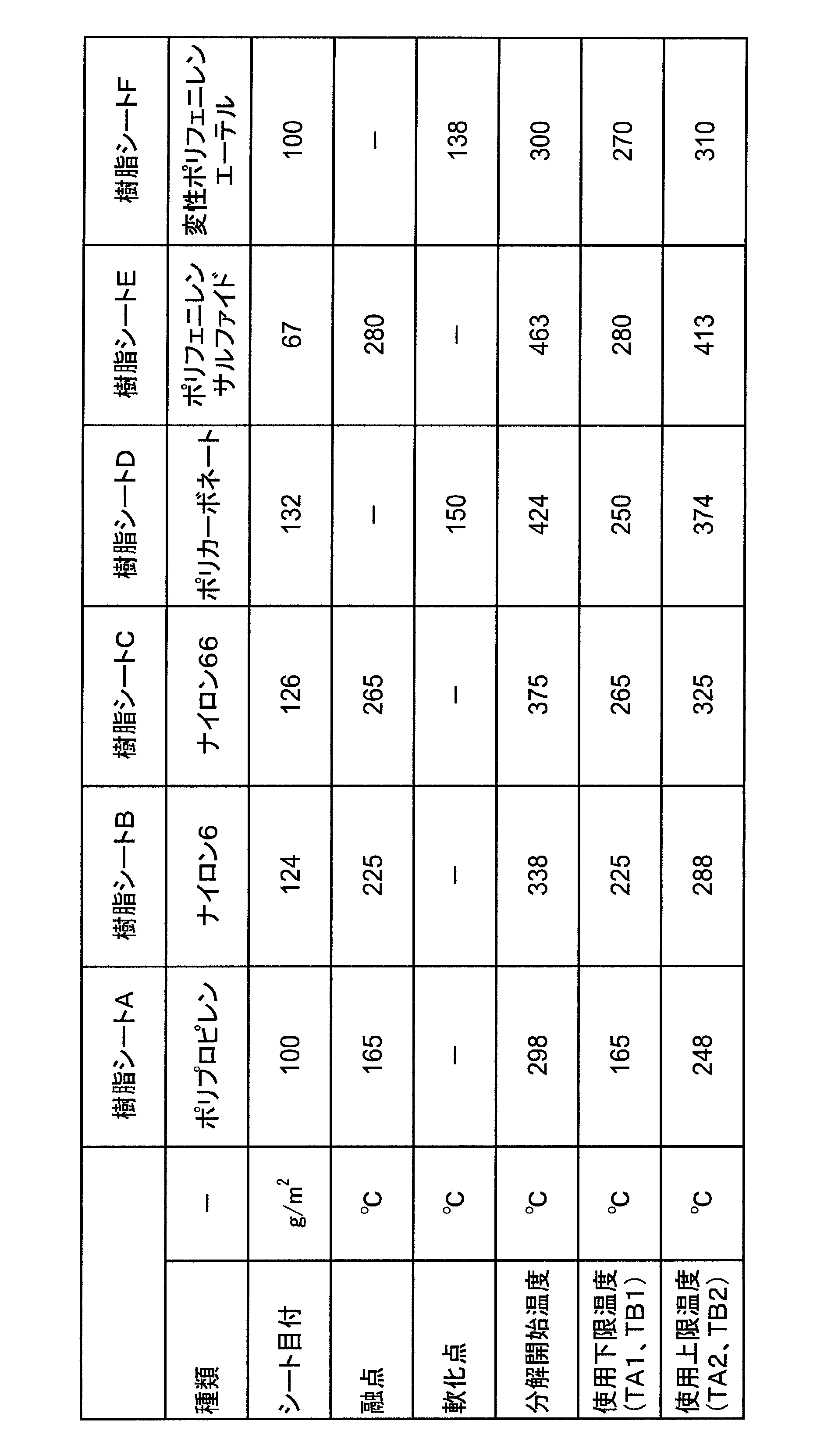
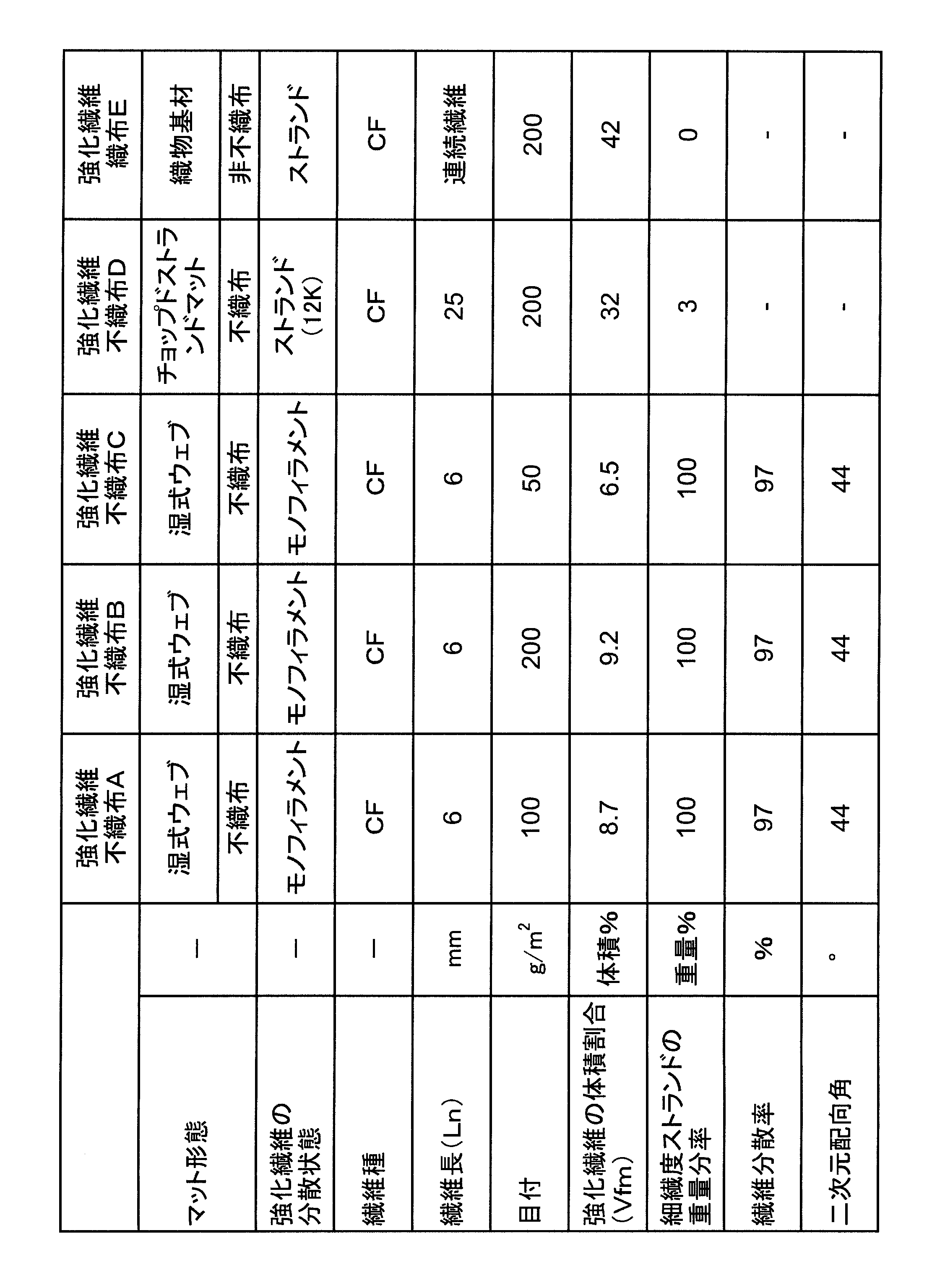
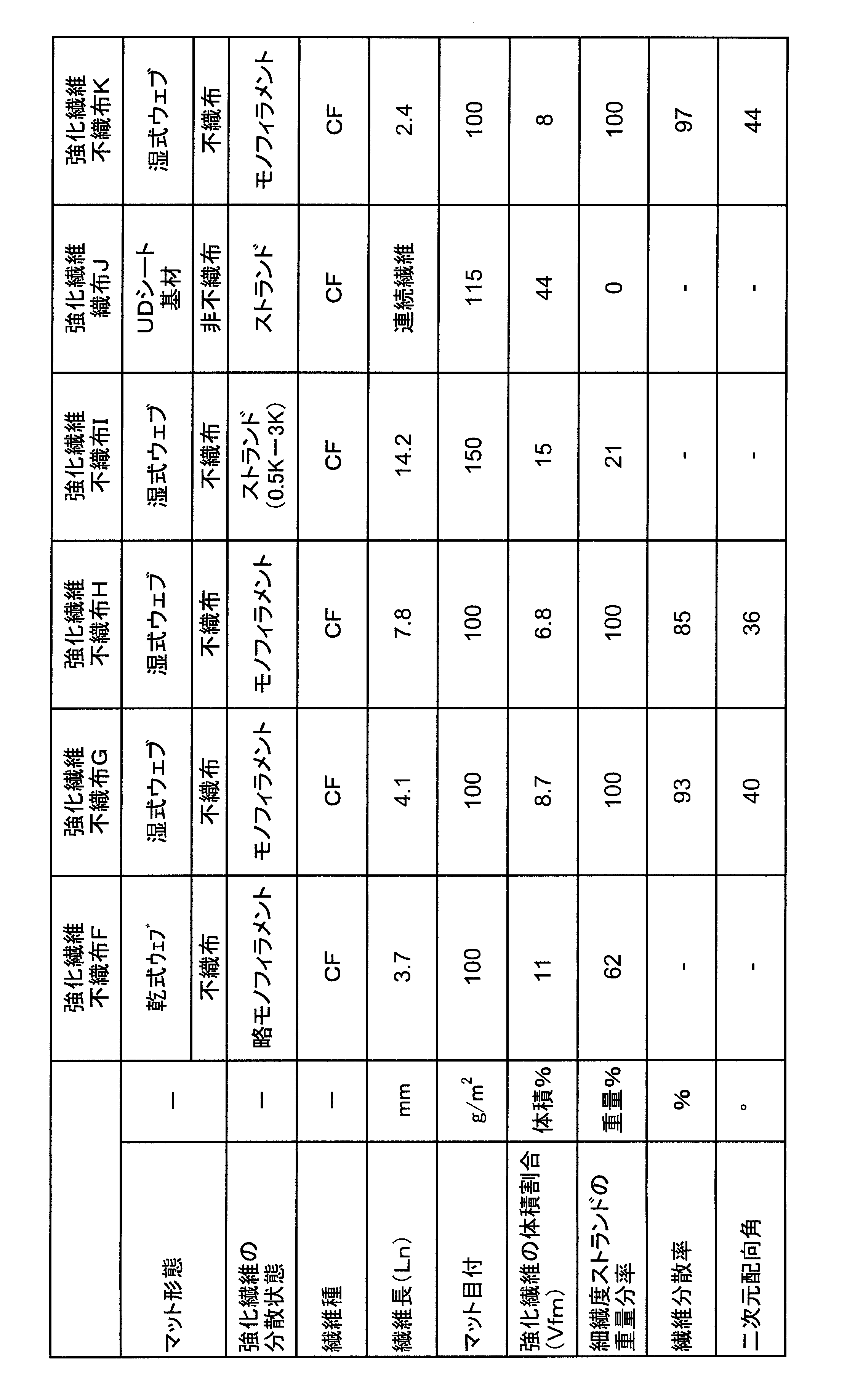

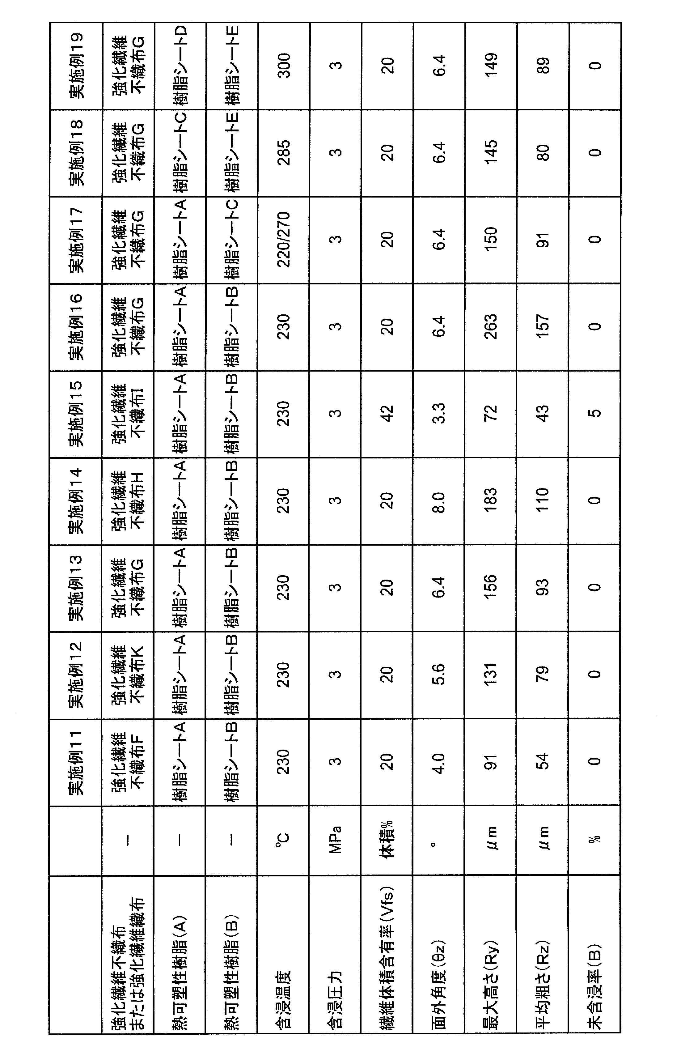
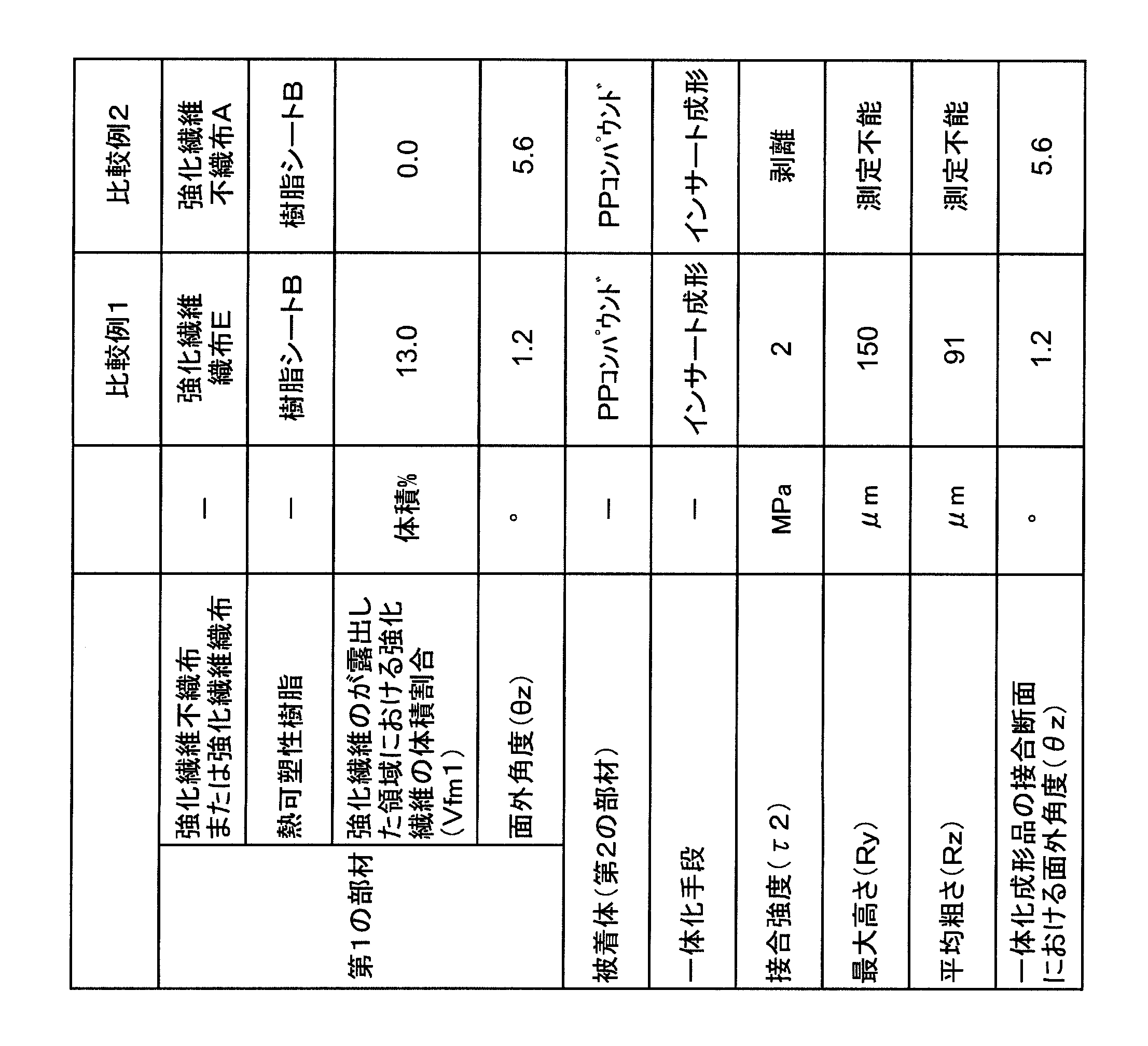
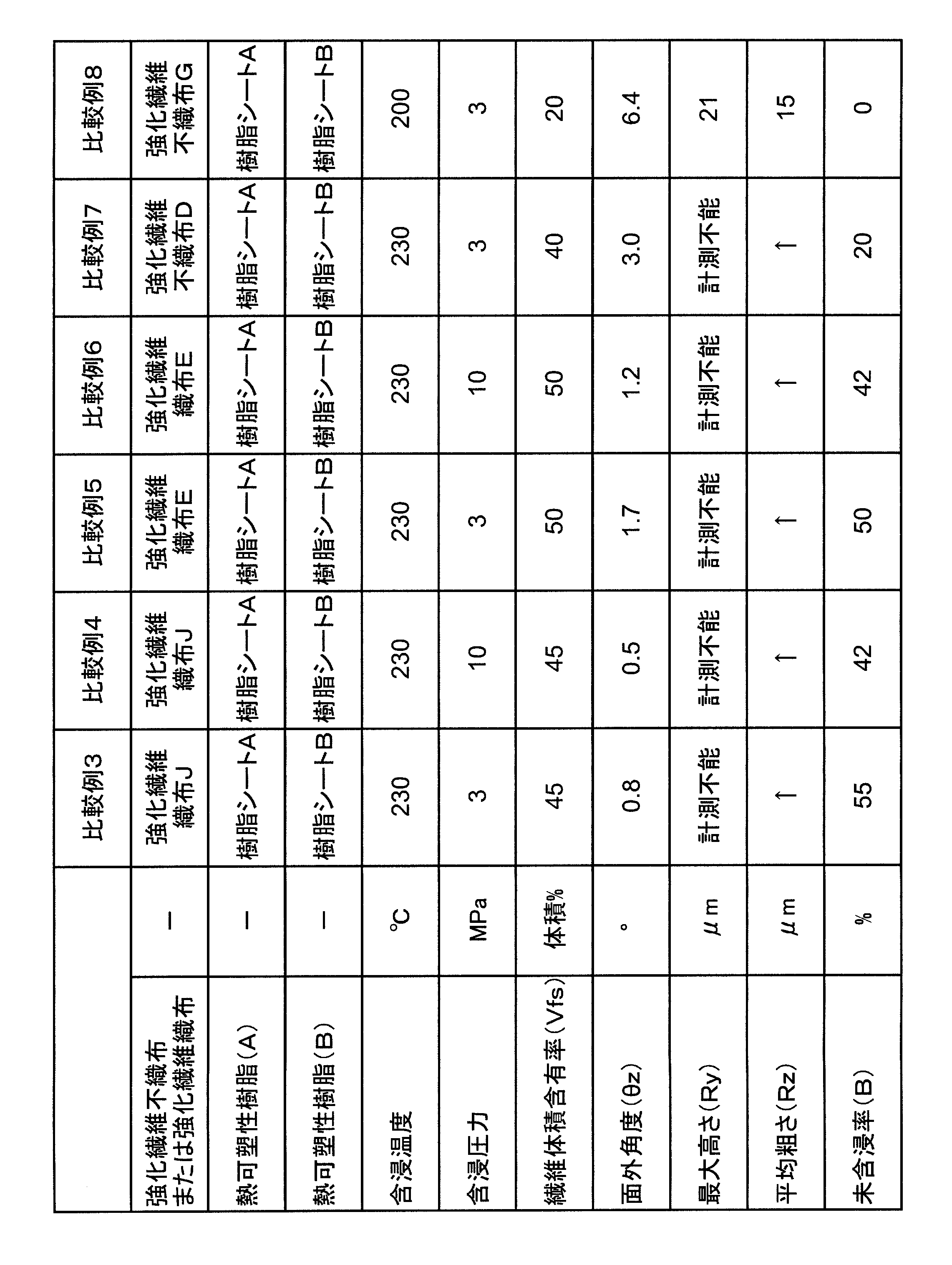

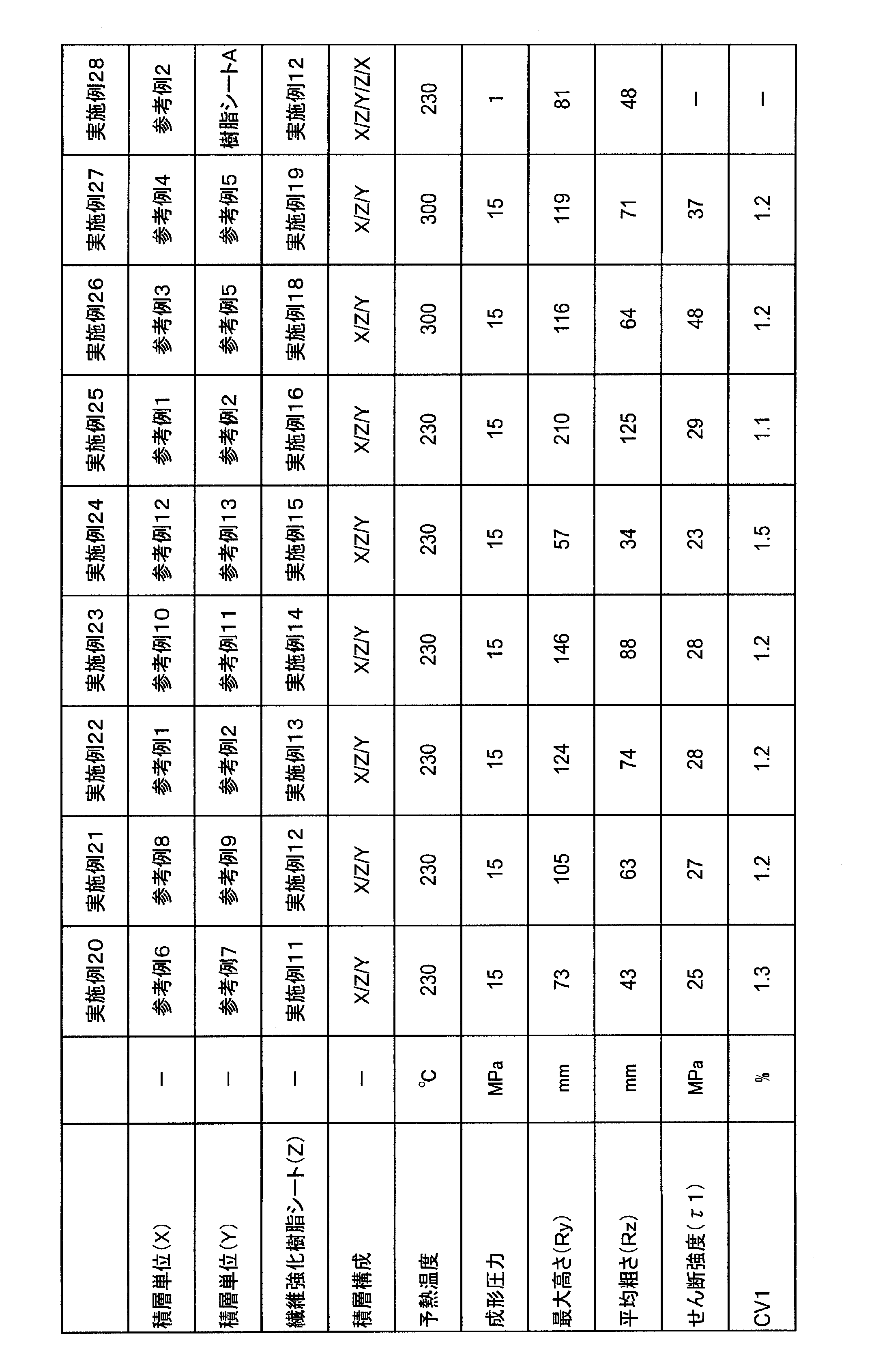

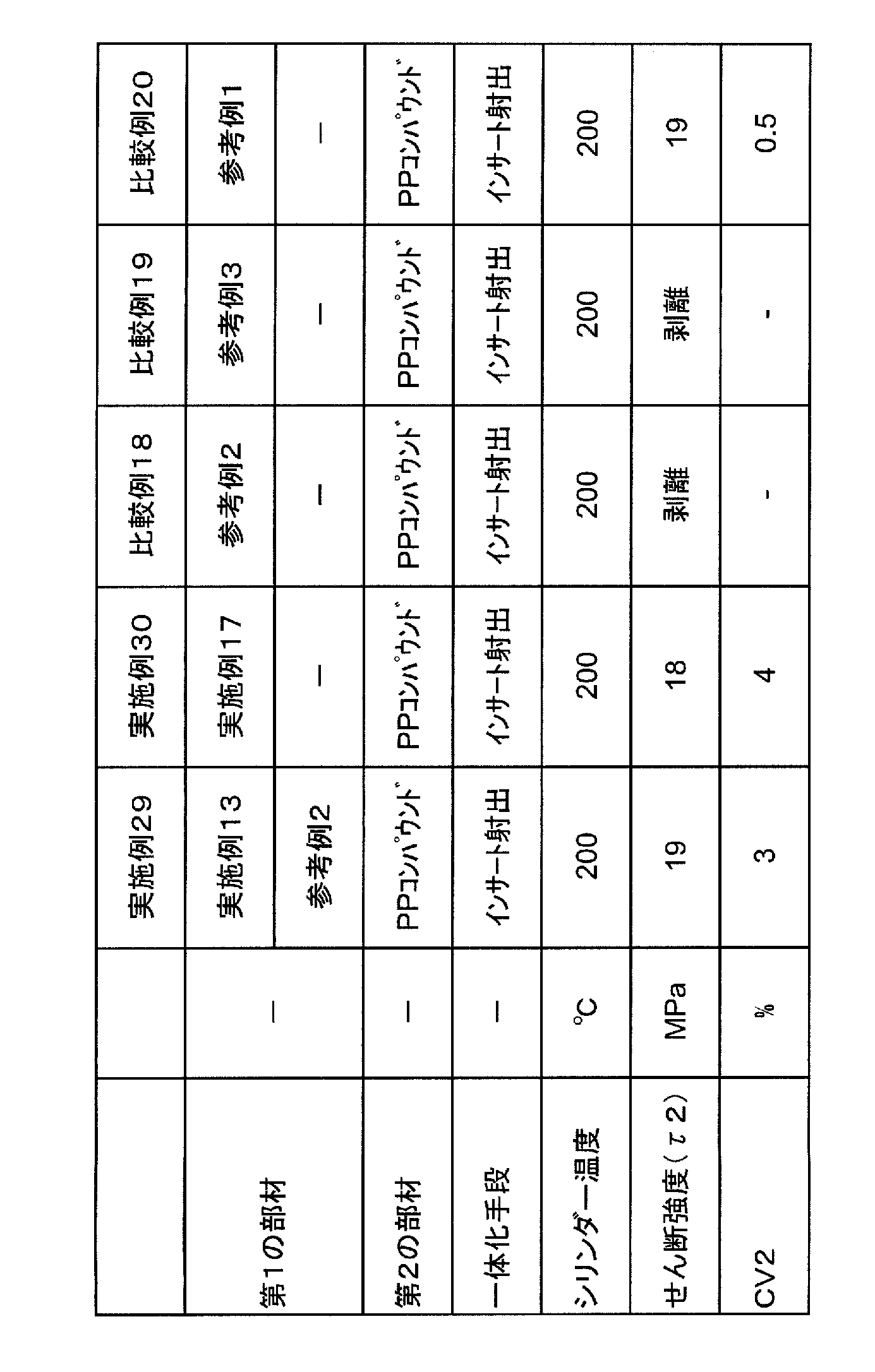
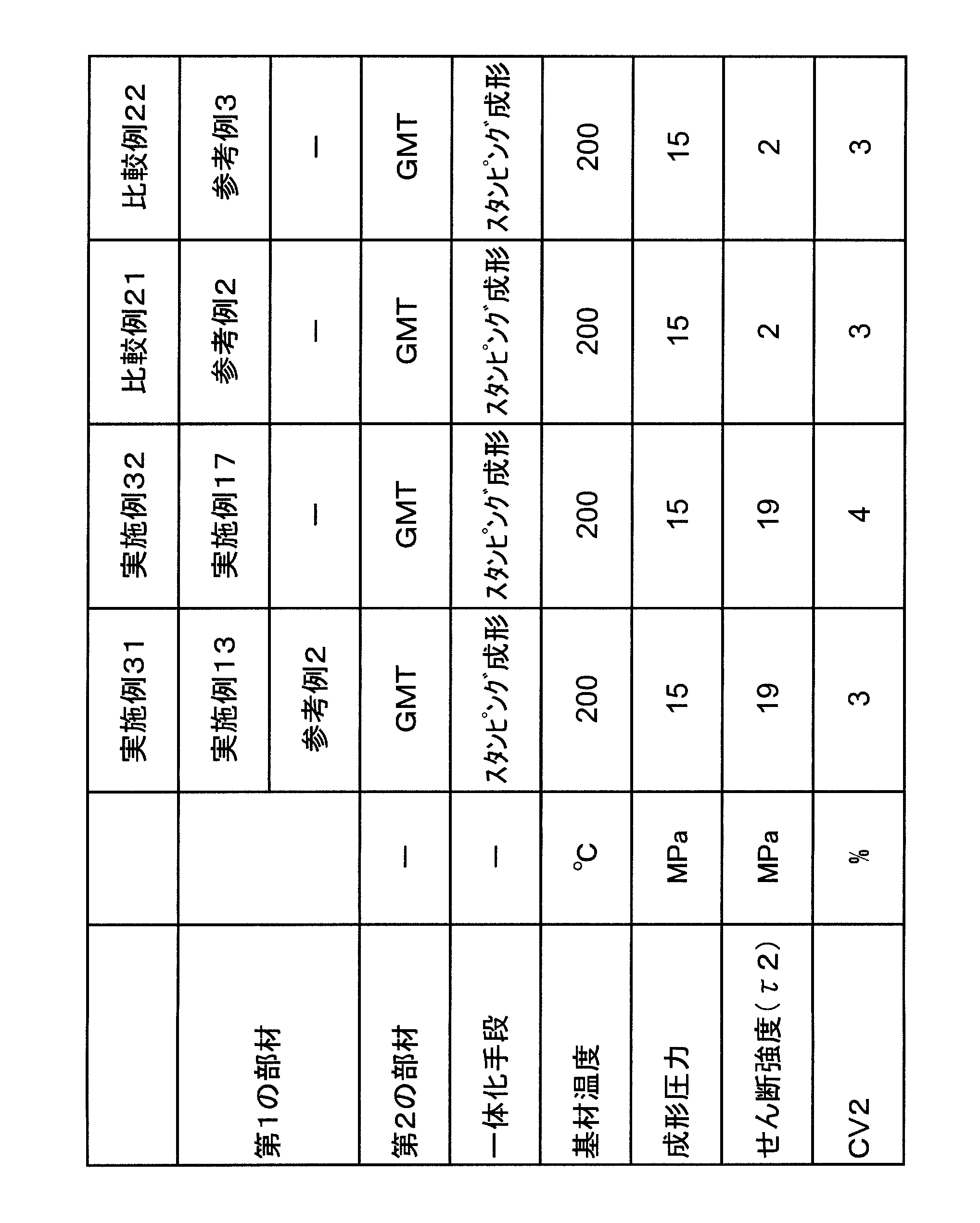
2、5、9、10、11,12,13,14,15,16 強化繊維(単繊維)
3 繊維強化樹脂シートにおける熱可塑性樹脂(A)が含浸されてなる層
6 繊維強化樹脂シートにおける熱可塑性樹脂(B)が含浸されてなる層
7 繊維強化樹脂シートにおける熱可塑性樹脂(A)が含浸されてなる層
17 二次元接触角、二次元配向角
18、22,23 成形体
19、24、25 熱可塑性樹脂(A)を基質とする階層
20、26、27 熱可塑性樹脂(B)を基質とする階層
31 熱可塑性樹脂(A)
32 熱可塑性樹脂(B)
33 繊維強化樹脂シートの界面層
34 界面層における最も窪みの大きい凹部
35 界面層における最も突出の大きい凸部
36 界面層における最も窪みの小さい凹部
37 界面層における最も突出の小さい凸部
38 せん断強度τ1の評価に供する試験片
40 せん断強度τ2の評価に供する試験片
39、41 切欠き
42、45 一体化成形品
43、46 第1の部材
44、47 第2の部材
48、52、56 プリフォーム
49、57 積層単位(X)
50、54、58 積層単位(Y)
Claims (15)
- 強化繊維から構成される不織布の厚み方向の一方の側に、熱可塑性樹脂(A)が含浸されてなる繊維強化樹脂シートであって、次の(I)または(II)のいずれかの条件を満たす、繊維強化樹脂シート:
(I)前記不織布の厚み方向のもう一方の側に不織布を構成する強化繊維が露出した領域を有する;
(II)前記不織布の厚み方向のもう一方の側に熱可塑性樹脂(B)が含浸されており、前記不織布は強化繊維の体積割合Vfmが20体積%以下であり、前記シート中において、熱可塑性樹脂(A)と熱可塑性樹脂(B)とが最大高さRy50μm以上、平均粗さRz30μm以上の凹凸形状を有して界面層を形成してなる。 - 強化繊維から構成される不織布の厚み方向の一方の側に、熱可塑性樹脂(A)が含浸されてなる繊維強化樹脂シートであって、前記条件(I)を満たす、請求項1に記載の繊維強化樹脂シート。
- 強化繊維の露出した領域における強化繊維の体積割合Vfmが20体積%以下である、請求項2に記載の繊維強化樹脂シート。
- 強化繊維から構成される不織布の厚み方向の一方の側に、熱可塑性樹脂(A)が含浸されてなる繊維強化樹脂シートであって、前記条件(II)を満たす、請求項1に記載の繊維強化樹脂シート。
- 熱可塑性樹脂(A)の可使温度域および熱可塑性樹脂(B)の可使温度域が、少なくとも5℃以上の温度範囲を持って重複する、請求項4に記載の繊維強化樹脂シート。
- 前記不織布は、不連続性強化繊維が略モノフィラメント状に分散してなる、請求項1~5のいずれかに記載の繊維強化樹脂シート。
- 前記シート中における強化繊維の面外角度θzが5°以上である、請求項1~6のいずれかに記載の繊維強化樹脂シート。
- 前記不織布を構成する強化繊維が炭素繊維である、請求項1~7のいずれかに記載の繊維強化樹脂シート。
- 請求項2または3に記載の繊維強化樹脂シートで構成される第1の部材に、熱可塑性樹脂(B)で構成される別の成形体である第2の部材を、前記繊維強化樹脂シートにおける強化繊維が露出した領域に熱可塑性樹脂(B)が含浸することで接合してなる、一体化成形品。
- 請求項4または5に記載の繊維強化樹脂シート、またはそれを含んでなる成形体である第1の部材と、別の成形体である第2の部材とを接合してなる、一体化成形品。
- 熱可塑性樹脂(A)および熱可塑性樹脂(B)とが最大高さRy50μm以上、平均粗さRz30μm以上の凹凸形状を有して界面層を形成してなる、請求項9または10に記載の一体化成形品。
- 強化繊維から構成される不織布に、熱可塑性樹脂(A)および熱可塑性樹脂(B)が含浸され、熱可塑性樹脂(A)と熱可塑性樹脂(B)とが最大高さRy50μm以上、平均粗さRz30μm以上の凹凸形状を有して界面層を形成してなる、一体化成形品。
- 請求項9~11のいずれかに記載の一体化成形品を製造する方法であって、前記第2の部材が射出成形による成形体であり、第2の部材をインサート射出成形またはアウトサート射出成形により第1の部材に接合する、一体化成形品の製造方法。
- 請求項9~11のいずれかに記載の一体化成形品を製造する方法であって、前記第2の部材がプレス成形による成形体であり、第2の部材をプレス成形により第1の部材に接合する、一体化成形品の製造方法。
- 自動車内外装、電気・電子機器筐体、自転車、スポーツ用品用構造材、航空機内装材、輸送用箱体として用いられる、請求項9~12のいずれかに記載の一体化成形品。
Priority Applications (4)
| Application Number | Priority Date | Filing Date | Title |
|---|---|---|---|
| CN201380059276.0A CN104781317B (zh) | 2012-12-26 | 2013-12-06 | 纤维增强树脂片材、一体化成型品及它们的制造方法 |
| EP13868075.6A EP2940065B1 (en) | 2012-12-26 | 2013-12-06 | Fiber-reinforced resin sheet, integrated molded product and process for producing same |
| KR1020157005430A KR20150100607A (ko) | 2012-12-26 | 2013-12-06 | 섬유 강화 수지 시트, 일체화 성형품 및 그들의 제조 방법 |
| US14/442,764 US10093777B2 (en) | 2012-12-26 | 2013-12-06 | Fiber-reinforced resin sheet, integrated molded product and process for producing same |
Applications Claiming Priority (4)
| Application Number | Priority Date | Filing Date | Title |
|---|---|---|---|
| JP2012282880A JP5626330B2 (ja) | 2012-12-26 | 2012-12-26 | 繊維強化樹脂シート、成形体、一体化成形品およびそれらの製造方法、ならびに実装部材 |
| JP2012-282880 | 2012-12-26 | ||
| JP2013-044003 | 2013-03-06 | ||
| JP2013044003A JP5641080B2 (ja) | 2013-03-06 | 2013-03-06 | 繊維強化樹脂シート、一体化成形品およびその製造方法、並びに実装部材 |
Publications (1)
| Publication Number | Publication Date |
|---|---|
| WO2014103658A1 true WO2014103658A1 (ja) | 2014-07-03 |
Family
ID=51020752
Family Applications (1)
| Application Number | Title | Priority Date | Filing Date |
|---|---|---|---|
| PCT/JP2013/082762 Ceased WO2014103658A1 (ja) | 2012-12-26 | 2013-12-06 | 繊維強化樹脂シート、一体化成形品およびそれらの製造方法 |
Country Status (6)
| Country | Link |
|---|---|
| US (1) | US10093777B2 (ja) |
| EP (1) | EP2940065B1 (ja) |
| KR (1) | KR20150100607A (ja) |
| CN (1) | CN104781317B (ja) |
| TW (1) | TWI609900B (ja) |
| WO (1) | WO2014103658A1 (ja) |
Cited By (18)
| Publication number | Priority date | Publication date | Assignee | Title |
|---|---|---|---|---|
| JP2015189176A (ja) * | 2014-03-28 | 2015-11-02 | マツダ株式会社 | 金属部材と樹脂部材との接合方法およびその方法において使用される樹脂部材 |
| CN105563817A (zh) * | 2014-10-29 | 2016-05-11 | 丰田自动车株式会社 | 生产纤维增强树脂模塑构件的方法和连接构件的方法 |
| WO2016115508A1 (en) * | 2015-01-16 | 2016-07-21 | Weatherford Technology Holdings, Llc | Molded composite centralizer |
| JP2016141074A (ja) * | 2015-02-03 | 2016-08-08 | 国立研究開発法人産業技術総合研究所 | 成形体の製造方法 |
| CN107002365A (zh) * | 2014-11-26 | 2017-08-01 | 东丽株式会社 | 碳纤维毡、坯料、片材料和成型品 |
| US20170326820A1 (en) * | 2014-11-18 | 2017-11-16 | Toray Industries, Inc. | Laminate, integrated molding, and method of producing same |
| JP2018149748A (ja) * | 2017-03-13 | 2018-09-27 | 株式会社東芝 | 膜部材およびその製造方法 |
| WO2019188873A1 (ja) * | 2018-03-30 | 2019-10-03 | 東レ株式会社 | プレス成形品の製造方法 |
| WO2019220914A1 (ja) * | 2018-05-18 | 2019-11-21 | 三菱重工業株式会社 | 複合材の製造方法および複合材 |
| JP2020029083A (ja) * | 2018-08-15 | 2020-02-27 | 日軽メタル株式会社 | 皮革積層体、シート材、皮革積層体の製造方法、樹脂含浸アルミニウム不織布、樹脂含浸アルミニウム不織布の製造方法、積層体、積層体の製造方法及び電子機器用ケース |
| WO2020235488A1 (ja) | 2019-05-23 | 2020-11-26 | 東レ株式会社 | 繊維強化樹脂基材の製造方法、繊維強化樹脂基材、およびその一体化成形品 |
| WO2020235490A1 (ja) | 2019-05-23 | 2020-11-26 | 東レ株式会社 | 繊維強化樹脂基材、一体化成形品および繊維強化樹脂基材の製造方法 |
| CN112384364A (zh) * | 2018-07-11 | 2021-02-19 | 麦格纳外饰公司 | 耐火smc层合体 |
| WO2021131382A1 (ja) | 2019-12-23 | 2021-07-01 | 東レ株式会社 | 複合プリプレグおよび繊維強化樹脂成形体 |
| US11084187B2 (en) | 2015-04-17 | 2021-08-10 | Mitsubishi Chemical Corporation | Fiber-reinforced composite material molded article and method for manufacturing same |
| JPWO2022107709A1 (ja) * | 2020-11-20 | 2022-05-27 | ||
| EP3263332B1 (en) * | 2015-02-27 | 2022-06-08 | Toray Industries, Inc. | Resin supply material, preform, and method for producing fiber-reinforced resin |
| KR20240090152A (ko) | 2021-10-06 | 2024-06-21 | 도레이 카부시키가이샤 | 프리프레그, 섬유 강화 수지 성형체 및 일체화 성형품 |
Families Citing this family (48)
| Publication number | Priority date | Publication date | Assignee | Title |
|---|---|---|---|---|
| CN105073403B (zh) * | 2013-04-02 | 2018-08-24 | 东丽株式会社 | 夹层层合体、夹层结构体和使用了该夹层结构体的一体化成型品及它们的制造方法 |
| WO2015029453A1 (ja) * | 2013-08-30 | 2015-03-05 | Art&Tech株式会社 | テキスタイル調インモールド用シート、その製造方法、プレフォーム成形体、テキスタイル調樹脂成形体及びその製造方法 |
| JP6254853B2 (ja) * | 2014-01-22 | 2017-12-27 | 株式会社エンプラス | 2色成形方法及び2色成形体 |
| US11440270B2 (en) * | 2014-04-24 | 2022-09-13 | Teijin Limited | Carbon fiber reinforced resin processed product having end surface and method of manufacturing the same |
| JP6602552B2 (ja) | 2015-04-14 | 2019-11-06 | 国立大学法人岐阜大学 | 成形体の製造方法 |
| TW201714952A (zh) | 2015-09-02 | 2017-05-01 | Jsr Corp | 組成物及成形體 |
| US10343351B2 (en) * | 2015-09-08 | 2019-07-09 | Johns Manville | Fiber-reinforced composites made with multi-part thermoplastic polymers |
| EP3175763A1 (de) * | 2015-12-02 | 2017-06-07 | Miele & Cie. KG | Geschirrkorb, insbesondere besteckschublade |
| US20170156487A1 (en) * | 2015-12-07 | 2017-06-08 | Larry Tang | Bi-fold table |
| KR101843006B1 (ko) * | 2016-04-20 | 2018-03-29 | 주식회사 한국카본 | 고성능 피로저항 및 고단열 특성을 가지는 유리강화섬유 발포수지 폼을 적용한 운송체용 구조체 및 그 제조방법 |
| WO2017203893A1 (ja) | 2016-05-27 | 2017-11-30 | 三菱瓦斯化学株式会社 | 材料および成形品 |
| CA3028020A1 (en) * | 2016-06-23 | 2017-12-28 | Fpinnovations | Wood pulp fiber- or cellulose filament-reinforced bulk molding compounds, composites, compositions and methods for preparation thereof |
| JP7091660B2 (ja) * | 2016-09-26 | 2022-06-28 | 東レ株式会社 | 電子機器筐体およびその製造方法 |
| WO2018056434A1 (ja) * | 2016-09-26 | 2018-03-29 | 東レ株式会社 | 電子機器筐体 |
| CN110072693B (zh) * | 2016-12-22 | 2021-12-24 | 东丽株式会社 | 复合结构体及其制造方法 |
| US20180186043A1 (en) * | 2017-01-04 | 2018-07-05 | Brunswick Corporation | Systems and Methods for Manufacturing Boat Parts |
| US20200346441A1 (en) * | 2017-02-02 | 2020-11-05 | Toray Industries, Inc. | Fiber-reinforced resin forming material |
| US10301828B2 (en) * | 2017-02-28 | 2019-05-28 | Jumpstart Consultants, Inc. | Underlayment material |
| CN209616539U (zh) * | 2017-03-15 | 2019-11-12 | 新秀丽Ip控股有限责任公司 | 行李箱壳体及用于制造行李箱壳体的装置 |
| EP3595853A4 (en) | 2017-03-16 | 2020-12-23 | Guerrilla Industries LLC | COMPOSITE STRUCTURES AND PROCESSES FOR FORMING COMPOSITE STRUCTURES |
| JP7104695B2 (ja) * | 2017-06-08 | 2022-07-21 | クラレクラフレックス株式会社 | 繊維構造体、成形体及び吸音材 |
| US11283128B2 (en) | 2017-08-30 | 2022-03-22 | Honda Motor Co., Ltd. | Laminate, in-vehicle battery containing body, and method for producing in-vehicle battery containing body |
| EP3705257B1 (en) * | 2017-10-30 | 2023-07-12 | Kuraray Co., Ltd. | Waterproof component and electronic equipment provided with the same, method for waterproofing an insert molded body, and method for waterproofing electronic equipment |
| DE102017222652A1 (de) * | 2017-12-13 | 2019-06-13 | Bayerische Motoren Werke Aktiengesellschaft | Faserverstärkte Fahrzeugkarosserie |
| US11364690B2 (en) | 2018-02-08 | 2022-06-21 | Giant Manufacturing Co., Ltd. | Resin-based composite structure and method for forming resin-based composite structure |
| EP3778211A4 (en) * | 2018-03-30 | 2021-12-15 | Toray Industries, Inc. | MOLDED ARTICLE AND MOLDED ARTICLE MANUFACTURING PROCESS |
| JP6781227B2 (ja) * | 2018-09-26 | 2020-11-04 | 第一工業製薬株式会社 | 電池被覆シートおよび電池パック |
| JP7145024B2 (ja) * | 2018-09-28 | 2022-09-30 | 株式会社シマノ | 樹脂成形体 |
| EP3860834B1 (en) * | 2018-10-03 | 2025-12-10 | Zephyros, Inc. | Composite structure and method of producing the same |
| AU2019396247A1 (en) * | 2018-11-30 | 2021-06-10 | Arris Composites Inc. | Compression-molded fiber-composite parts and methods of fabrication |
| JPWO2020137948A1 (ja) * | 2018-12-25 | 2021-11-04 | 帝人株式会社 | 繊維強化熱可塑性樹脂成形体及びその製造方法 |
| JP7215182B2 (ja) * | 2019-01-18 | 2023-01-31 | セイコーエプソン株式会社 | 液体吸収体、インク吸収器および液滴吐出装置 |
| JP6773824B2 (ja) * | 2019-01-25 | 2020-10-21 | ポリプラスチックス株式会社 | 複合成形品 |
| CN113474139A (zh) * | 2019-02-14 | 2021-10-01 | 仓敷纺绩株式会社 | 纤维增强树脂成形体及其中所用的碳纤维片的制造方法 |
| US11434177B2 (en) | 2019-05-13 | 2022-09-06 | Rolls-Royce Plc | Ceramic matrix composite vane with hybrid construction |
| JP7047923B2 (ja) * | 2019-05-23 | 2022-04-05 | 東レ株式会社 | プリプレグ、積層体および成形品 |
| CN110354511B (zh) * | 2019-07-10 | 2021-02-26 | 东莞市文博工艺品有限公司 | 一种硅胶公仔生产流水线 |
| CN112208172A (zh) * | 2019-07-12 | 2021-01-12 | 大赛璐美华株式会社 | 复合成型体及其制造方法 |
| CN114728439B (zh) | 2019-11-13 | 2024-05-14 | 仓敷纺绩株式会社 | 真空成形用树脂一体化纤维片、采用其的成形体和成形体的制造方法 |
| JP7385488B2 (ja) * | 2020-02-13 | 2023-11-22 | 日立造船株式会社 | 繊維含有シートの製造方法 |
| DE102020128528A1 (de) * | 2020-10-29 | 2022-05-05 | Kautex Textron Gmbh & Co. Kg | Batterieschale aufweisend ein Verstärkungsvlies, Herstellverfahren und Traktionsbatterie |
| WO2022138264A1 (ja) * | 2020-12-22 | 2022-06-30 | 寿屋フロンテ株式会社 | 車両用内装材及びシートバックパネル |
| US11572124B2 (en) | 2021-03-09 | 2023-02-07 | Guerrilla Industries LLC | Composite structures and methods of forming composite structures |
| CN113291011A (zh) * | 2021-06-01 | 2021-08-24 | 华东理工大学 | 一种可变密度的热塑性复合材料夹芯结构及其制备方法和应用 |
| KR20240138536A (ko) * | 2022-02-03 | 2024-09-20 | 도레이 카부시키가이샤 | 회전익 |
| CN115175387B (zh) * | 2022-07-15 | 2025-09-16 | 上海骏珲新材料科技有限公司 | 自限温远红外碳纤维复合面状电热材料及其制备方法 |
| WO2024181658A1 (ko) * | 2023-02-27 | 2024-09-06 | 삼성전자 주식회사 | 전자 장치의 외장 커버, 이를 포함하는 전자 장치 및 그 제조 방법 |
| CN118164773B (zh) * | 2024-03-07 | 2026-02-06 | 西北工业大学 | 一种高导热单向碳/碳复合材料及其制备方法 |
Citations (16)
| Publication number | Priority date | Publication date | Assignee | Title |
|---|---|---|---|---|
| JPS6382743A (ja) | 1986-09-27 | 1988-04-13 | 三井東圧化学株式会社 | 接着性ポリオレフイン複層シ−ト及びその製造方法 |
| JPS6480520A (en) * | 1987-09-24 | 1989-03-27 | Kuraray Co | Stamping molding material |
| JPH0423515B2 (ja) | 1983-07-13 | 1992-04-22 | Sony Corp | |
| JPH04226346A (ja) | 1991-05-13 | 1992-08-17 | Hiraoka & Co Ltd | 耐熱性シート |
| JPH06262731A (ja) | 1993-03-15 | 1994-09-20 | Kuraray Co Ltd | 複合材料 |
| JPH08230114A (ja) | 1995-03-01 | 1996-09-10 | Kawasaki Steel Corp | 抄造法スタンパブルシート、軽量スタンパブルシート成形品および軽量スタンパブルシート表皮貼合品 |
| JPH0938968A (ja) * | 1995-08-02 | 1997-02-10 | Mitsubishi Chem Corp | 外観の改良されたスタンパブルシートの製造方法 |
| JP2002104091A (ja) | 2000-09-27 | 2002-04-09 | Kawasaki Steel Corp | 自動車用天井材および分散法スタンパブルシート |
| JP2003136553A (ja) | 2001-11-06 | 2003-05-14 | Sumitomo Chem Co Ltd | 多層成形体およびその製造方法 |
| WO2006041771A1 (en) | 2004-10-04 | 2006-04-20 | E.I. Dupont De Nemours And Company | Polymer assemblies with decorative surfaces |
| JP2006205436A (ja) | 2005-01-26 | 2006-08-10 | Toray Ind Inc | 繊維強化複合材料板およびそれを用いた成形品 |
| JP3906319B2 (ja) | 2002-12-27 | 2007-04-18 | 東レ株式会社 | 積層体、一体化成形品、および、それらの製造方法 |
| JP2008049702A (ja) | 2006-07-28 | 2008-03-06 | Toray Ind Inc | 成形品およびその製造方法 |
| JP2008050598A (ja) | 2006-07-28 | 2008-03-06 | Toray Ind Inc | 繊維強化複合材料および一体化成形品 |
| JP2008230238A (ja) | 2007-02-22 | 2008-10-02 | Toray Ind Inc | 繊維強化複合材料板、およびそれを用いた成形品 |
| JP2014019780A (ja) * | 2012-07-18 | 2014-02-03 | Toray Ind Inc | 繊維強化樹脂成形体および繊維強化樹脂シート |
Family Cites Families (12)
| Publication number | Priority date | Publication date | Assignee | Title |
|---|---|---|---|---|
| JPH06320655A (ja) | 1993-05-11 | 1994-11-22 | Nippon Steel Corp | 繊維強化熱可塑性樹脂多孔質成形品およびその成形方法 |
| JPH08224793A (ja) | 1995-02-20 | 1996-09-03 | Kobe Steel Ltd | 繊維強化樹脂成形品の製造方法 |
| WO1996026822A1 (en) | 1995-03-01 | 1996-09-06 | Kawasaki Steel Corporation | Stampable sheet made by papermaking technique and method for manufacturing lightweight molded stampable sheet |
| CN100344443C (zh) * | 2002-04-23 | 2007-10-24 | 东丽株式会社 | 预浸料坯及其制造方法、以及成形品 |
| CN100546443C (zh) * | 2002-12-27 | 2009-09-30 | 东丽株式会社 | 一种电子设备的壳体及其制造方法 |
| JP4023515B2 (ja) | 2002-12-27 | 2007-12-19 | 東レ株式会社 | 熱接着用基材が用いられてなるプリフォーム、および積層体の製造方法 |
| KR20060022685A (ko) | 2003-06-11 | 2006-03-10 | 이 아이 듀폰 디 네모아 앤드 캄파니 | 상이한 열가소성 중합체의 연결 |
| TWI414543B (zh) * | 2006-02-24 | 2013-11-11 | Toray Industries | 纖維強化熱可塑性樹脂成形體、成形材料及其製法 |
| US20090208721A1 (en) * | 2006-07-28 | 2009-08-20 | Toray Industries, Inc. | Molded article and method for producing the same |
| JP2010253937A (ja) | 2009-03-31 | 2010-11-11 | Toray Ind Inc | 一体化成形品 |
| JP2012152982A (ja) | 2011-01-25 | 2012-08-16 | Quadrant Plastic Composites Japan Ltd | 積層板及び成形体 |
| CN105073403B (zh) * | 2013-04-02 | 2018-08-24 | 东丽株式会社 | 夹层层合体、夹层结构体和使用了该夹层结构体的一体化成型品及它们的制造方法 |
-
2013
- 2013-12-06 EP EP13868075.6A patent/EP2940065B1/en active Active
- 2013-12-06 KR KR1020157005430A patent/KR20150100607A/ko not_active Ceased
- 2013-12-06 CN CN201380059276.0A patent/CN104781317B/zh active Active
- 2013-12-06 WO PCT/JP2013/082762 patent/WO2014103658A1/ja not_active Ceased
- 2013-12-06 US US14/442,764 patent/US10093777B2/en active Active
- 2013-12-25 TW TW102148106A patent/TWI609900B/zh active
Patent Citations (16)
| Publication number | Priority date | Publication date | Assignee | Title |
|---|---|---|---|---|
| JPH0423515B2 (ja) | 1983-07-13 | 1992-04-22 | Sony Corp | |
| JPS6382743A (ja) | 1986-09-27 | 1988-04-13 | 三井東圧化学株式会社 | 接着性ポリオレフイン複層シ−ト及びその製造方法 |
| JPS6480520A (en) * | 1987-09-24 | 1989-03-27 | Kuraray Co | Stamping molding material |
| JPH04226346A (ja) | 1991-05-13 | 1992-08-17 | Hiraoka & Co Ltd | 耐熱性シート |
| JPH06262731A (ja) | 1993-03-15 | 1994-09-20 | Kuraray Co Ltd | 複合材料 |
| JPH08230114A (ja) | 1995-03-01 | 1996-09-10 | Kawasaki Steel Corp | 抄造法スタンパブルシート、軽量スタンパブルシート成形品および軽量スタンパブルシート表皮貼合品 |
| JPH0938968A (ja) * | 1995-08-02 | 1997-02-10 | Mitsubishi Chem Corp | 外観の改良されたスタンパブルシートの製造方法 |
| JP2002104091A (ja) | 2000-09-27 | 2002-04-09 | Kawasaki Steel Corp | 自動車用天井材および分散法スタンパブルシート |
| JP2003136553A (ja) | 2001-11-06 | 2003-05-14 | Sumitomo Chem Co Ltd | 多層成形体およびその製造方法 |
| JP3906319B2 (ja) | 2002-12-27 | 2007-04-18 | 東レ株式会社 | 積層体、一体化成形品、および、それらの製造方法 |
| WO2006041771A1 (en) | 2004-10-04 | 2006-04-20 | E.I. Dupont De Nemours And Company | Polymer assemblies with decorative surfaces |
| JP2006205436A (ja) | 2005-01-26 | 2006-08-10 | Toray Ind Inc | 繊維強化複合材料板およびそれを用いた成形品 |
| JP2008049702A (ja) | 2006-07-28 | 2008-03-06 | Toray Ind Inc | 成形品およびその製造方法 |
| JP2008050598A (ja) | 2006-07-28 | 2008-03-06 | Toray Ind Inc | 繊維強化複合材料および一体化成形品 |
| JP2008230238A (ja) | 2007-02-22 | 2008-10-02 | Toray Ind Inc | 繊維強化複合材料板、およびそれを用いた成形品 |
| JP2014019780A (ja) * | 2012-07-18 | 2014-02-03 | Toray Ind Inc | 繊維強化樹脂成形体および繊維強化樹脂シート |
Non-Patent Citations (7)
| Title |
|---|
| "Adhesives-Determination of tensile lap-shear strength of rigid-to-rigid bonded assemblies", JIS K6850, 1999 |
| "method for measuring the thickness of the carbon fiber woven fabric", JIS R7602, 1995 |
| "Method for measuring thickness of carbon fiber woven fabric", JIS R7602, 1995 |
| "Method for measuring unit area weight of carbon fiber woven fabric carbon fiber", JIS R7602, 1995 |
| "Plastics-Thermoplastic materials-Determination of Vicat softening temperature (VST) test", JIS K7206, 1999 |
| "Test method for interlaminar shear strength of carbon fiber reinforced plastic by double-notch specimen", JIS K7092, 2005 |
| "Testing Methods of Plastics by Thermogravimetry", JIS K7120, 1987 |
Cited By (33)
| Publication number | Priority date | Publication date | Assignee | Title |
|---|---|---|---|---|
| JP2015189176A (ja) * | 2014-03-28 | 2015-11-02 | マツダ株式会社 | 金属部材と樹脂部材との接合方法およびその方法において使用される樹脂部材 |
| CN105563817A (zh) * | 2014-10-29 | 2016-05-11 | 丰田自动车株式会社 | 生产纤维增强树脂模塑构件的方法和连接构件的方法 |
| JP2016083907A (ja) * | 2014-10-29 | 2016-05-19 | トヨタ自動車株式会社 | 繊維強化樹脂成形部材の製造方法と部材の接続方法 |
| US10155331B2 (en) | 2014-10-29 | 2018-12-18 | Toyota Jidosha Kabushiki Kaisha | Method of producing fiber-reinforced resin-molded member, and method of connecting members |
| US20170326820A1 (en) * | 2014-11-18 | 2017-11-16 | Toray Industries, Inc. | Laminate, integrated molding, and method of producing same |
| US10751957B2 (en) * | 2014-11-18 | 2020-08-25 | Toray Industries, Inc. | Laminate, integrated molding, and method of producing same |
| CN107002365B (zh) * | 2014-11-26 | 2020-01-14 | 东丽株式会社 | 碳纤维毡、坯料、片材料和成型品 |
| CN107002365A (zh) * | 2014-11-26 | 2017-08-01 | 东丽株式会社 | 碳纤维毡、坯料、片材料和成型品 |
| WO2016115508A1 (en) * | 2015-01-16 | 2016-07-21 | Weatherford Technology Holdings, Llc | Molded composite centralizer |
| JP2016141074A (ja) * | 2015-02-03 | 2016-08-08 | 国立研究開発法人産業技術総合研究所 | 成形体の製造方法 |
| EP3263332B1 (en) * | 2015-02-27 | 2022-06-08 | Toray Industries, Inc. | Resin supply material, preform, and method for producing fiber-reinforced resin |
| US11084187B2 (en) | 2015-04-17 | 2021-08-10 | Mitsubishi Chemical Corporation | Fiber-reinforced composite material molded article and method for manufacturing same |
| JP2018149748A (ja) * | 2017-03-13 | 2018-09-27 | 株式会社東芝 | 膜部材およびその製造方法 |
| TWI791803B (zh) * | 2018-03-30 | 2023-02-11 | 日商東麗股份有限公司 | 壓合成形品之製造方法及壓合成形品 |
| WO2019188873A1 (ja) * | 2018-03-30 | 2019-10-03 | 東レ株式会社 | プレス成形品の製造方法 |
| JP7163911B2 (ja) | 2018-03-30 | 2022-11-01 | 東レ株式会社 | プレス成形品の製造方法 |
| JPWO2019188873A1 (ja) * | 2018-03-30 | 2021-02-12 | 東レ株式会社 | プレス成形品の製造方法 |
| WO2019220914A1 (ja) * | 2018-05-18 | 2019-11-21 | 三菱重工業株式会社 | 複合材の製造方法および複合材 |
| CN110997268A (zh) * | 2018-05-18 | 2020-04-10 | 三菱重工业株式会社 | 复合材料的制造方法及复合材料 |
| JP2019199062A (ja) * | 2018-05-18 | 2019-11-21 | 三菱重工業株式会社 | 複合材の製造方法および複合材 |
| US11370183B2 (en) | 2018-05-18 | 2022-06-28 | Mitsubishi Heavy Industries, Ltd. | Composite material manufacturing method and composite material |
| CN112384364A (zh) * | 2018-07-11 | 2021-02-19 | 麦格纳外饰公司 | 耐火smc层合体 |
| JP7097292B2 (ja) | 2018-08-15 | 2022-07-07 | 日軽メタル株式会社 | 皮革積層体及びシート材 |
| JP2020029083A (ja) * | 2018-08-15 | 2020-02-27 | 日軽メタル株式会社 | 皮革積層体、シート材、皮革積層体の製造方法、樹脂含浸アルミニウム不織布、樹脂含浸アルミニウム不織布の製造方法、積層体、積層体の製造方法及び電子機器用ケース |
| WO2020235490A1 (ja) | 2019-05-23 | 2020-11-26 | 東レ株式会社 | 繊維強化樹脂基材、一体化成形品および繊維強化樹脂基材の製造方法 |
| WO2020235488A1 (ja) | 2019-05-23 | 2020-11-26 | 東レ株式会社 | 繊維強化樹脂基材の製造方法、繊維強化樹脂基材、およびその一体化成形品 |
| US12162186B2 (en) | 2019-05-23 | 2024-12-10 | Toray Industries, Inc. | Method for producing fiber-reinforced plastic substrate, and fiber-reinforced plastic substrate and integrated molding thereof |
| US12269225B2 (en) | 2019-05-23 | 2025-04-08 | Toray Industries, Inc. | Fiber-reinforced resin substrate, integrated molded article, and method for manufacturing fiber-reinforced resin substrate |
| WO2021131382A1 (ja) | 2019-12-23 | 2021-07-01 | 東レ株式会社 | 複合プリプレグおよび繊維強化樹脂成形体 |
| WO2022107709A1 (ja) | 2020-11-20 | 2022-05-27 | 東レ株式会社 | 繊維強化樹脂基材、プリフォーム、一体化成形品および繊維強化樹脂基材の製造方法 |
| JPWO2022107709A1 (ja) * | 2020-11-20 | 2022-05-27 | ||
| US12479187B2 (en) | 2020-11-20 | 2025-11-25 | Toray Industries, Inc. | Fiber-reinforced resin substrate, preform, integrated product, and method for producing fiber-reinforced resin substrate |
| KR20240090152A (ko) | 2021-10-06 | 2024-06-21 | 도레이 카부시키가이샤 | 프리프레그, 섬유 강화 수지 성형체 및 일체화 성형품 |
Also Published As
| Publication number | Publication date |
|---|---|
| CN104781317B (zh) | 2017-10-03 |
| EP2940065A4 (en) | 2016-08-24 |
| TW201443113A (zh) | 2014-11-16 |
| CN104781317A (zh) | 2015-07-15 |
| US10093777B2 (en) | 2018-10-09 |
| TWI609900B (zh) | 2018-01-01 |
| EP2940065B1 (en) | 2021-06-16 |
| US20150376353A1 (en) | 2015-12-31 |
| KR20150100607A (ko) | 2015-09-02 |
| EP2940065A1 (en) | 2015-11-04 |
Similar Documents
| Publication | Publication Date | Title |
|---|---|---|
| WO2014103658A1 (ja) | 繊維強化樹脂シート、一体化成形品およびそれらの製造方法 | |
| JP5626330B2 (ja) | 繊維強化樹脂シート、成形体、一体化成形品およびそれらの製造方法、ならびに実装部材 | |
| US11969984B2 (en) | Sandwich laminate, sandwich structure and unified molded product using same and processes for producing both | |
| JP5641080B2 (ja) | 繊維強化樹脂シート、一体化成形品およびその製造方法、並びに実装部材 | |
| JP6406011B2 (ja) | サンドイッチ構造体、それを用いた一体化成形品およびそれらの製造方法 | |
| JP6248466B2 (ja) | 繊維強化樹脂シート、一体成形品およびそれらの製造方法 | |
| JP6822147B2 (ja) | 構造体 | |
| JP6303849B2 (ja) | 繊維強化樹脂シート、一体化成形品およびそれらの製造方法 | |
| WO2017110532A1 (ja) | 構造体 | |
| JP5994737B2 (ja) | プレス成形用中間基材、プリフォーム、および成形品の製造方法 | |
| JP5994427B2 (ja) | プレス成形用中間基材、プリフォーム、および成形品の製造方法 | |
| JP2014028511A (ja) | プレス成形用中間基材、プリフォーム、および成形品の製造方法 | |
| JP6123965B1 (ja) | 構造体 |
Legal Events
| Date | Code | Title | Description |
|---|---|---|---|
| 121 | Ep: the epo has been informed by wipo that ep was designated in this application |
Ref document number: 13868075 Country of ref document: EP Kind code of ref document: A1 |
|
| ENP | Entry into the national phase |
Ref document number: 20157005430 Country of ref document: KR Kind code of ref document: A |
|
| WWE | Wipo information: entry into national phase |
Ref document number: 14442764 Country of ref document: US |
|
| WWE | Wipo information: entry into national phase |
Ref document number: 2013868075 Country of ref document: EP |
|
| NENP | Non-entry into the national phase |
Ref country code: DE |