WO2014103765A1 - Dispositif et procédé de décodage, et dispositif et procédé d'encodage - Google Patents
Dispositif et procédé de décodage, et dispositif et procédé d'encodage Download PDFInfo
- Publication number
- WO2014103765A1 WO2014103765A1 PCT/JP2013/083561 JP2013083561W WO2014103765A1 WO 2014103765 A1 WO2014103765 A1 WO 2014103765A1 JP 2013083561 W JP2013083561 W JP 2013083561W WO 2014103765 A1 WO2014103765 A1 WO 2014103765A1
- Authority
- WO
- WIPO (PCT)
- Prior art keywords
- unit
- tile
- size
- image
- decoding
- Prior art date
- Legal status (The legal status is an assumption and is not a legal conclusion. Google has not performed a legal analysis and makes no representation as to the accuracy of the status listed.)
- Ceased
Links
Images










Classifications
-
- H—ELECTRICITY
- H04—ELECTRIC COMMUNICATION TECHNIQUE
- H04N—PICTORIAL COMMUNICATION, e.g. TELEVISION
- H04N19/00—Methods or arrangements for coding, decoding, compressing or decompressing digital video signals
- H04N19/44—Decoders specially adapted therefor, e.g. video decoders which are asymmetric with respect to the encoder
Definitions
- the present technology relates to a decoding device and a decoding method, and an encoding device and an encoding method, and in particular, a decoding device and a decoding method capable of reducing an information amount of a parameter indicating a tile size, and a code
- the present invention relates to a coding apparatus and a coding method.
- JVCVC Joint Collaboration-Team-Video Coding
- a tile (TILE) is defined as a tool for parallel processing (for example, see Non-Patent Document 1).
- a tile is one of picture division units.
- the LCU included in each tile is processed in the raster scan order, and the tile included in each picture is processed in the raster scan order.
- the slice may include a tile, and there may be a slice boundary in the middle of the tile.
- Non-Patent Document 2 proposes designating information indicating where a tile starts in image compression information and transmitting it to the decoding side.
- Non-Patent Document 3 in the PPS (Picture Parameter Set) in the image compression information, the size of the tile in the row (row) direction and the column (column) direction is set to LCU (Largest) called CTB (Coding Tree Block). It has been proposed to specify Coding Unit) as a unit.
- Non-Patent Document 3 defines the minimum values of the horizontal and vertical widths of tiles as a profile of the HEVC standard.
- the parameter value indicating the tile size is unnecessarily large and the amount of information is large.
- the present technology has been made in view of such a situation, and makes it possible to reduce the amount of information of a parameter indicating the size of a tile.
- the decoding device includes a decoding unit that decodes encoded data obtained by encoding an image in units of tiles, and a ratio between a minimum tile size and a CTB (Coding Tree) size. And a control unit that controls the decoding by the decoding unit using the parameter indicating the size of the tile of the image set in the above.
- the decoding method according to the first aspect of the present technology corresponds to the decoding device according to the first aspect of the present technology.
- encoded data obtained by encoding an image in units of tiles is decoded and set according to a ratio between a minimum tile size and a CTB (CodingCoTree Block) size.
- the decoding is controlled using a parameter indicating the tile size of the image.
- An encoding device includes an encoding unit that encodes an image in units of tiles to generate encoded data, the encoded data generated by the encoding unit, and a tile size
- the encoding apparatus includes: a transmission unit configured to transmit a parameter indicating a tile size of the image set according to a ratio between a minimum value and a size of CTB (Coding
- the encoding method according to the second aspect of the present technology corresponds to the encoding device according to the second aspect of the present technology.
- encoded data is generated by encoding an image in units of tiles, and the ratio between the encoded data and the minimum size of the tile and the size of the CTB (Coding Tree Block) A parameter indicating the size of the tile of the image set accordingly is transmitted.
- CTB Coding Tree Block
- the decoding device according to the first aspect and the encoding device according to the second aspect can be realized by causing a computer to execute a program.
- a program to be executed by a computer is transmitted through a transmission medium or recorded on a recording medium, Can be provided.
- the decoding device of the first aspect and the encoding device of the second aspect may be independent devices or may be internal blocks constituting one device.
- encoded data can be decoded using a parameter indicating the size of a tile with a reduced amount of information.
- FIG. It is a flowchart explaining the decoding process of FIG. It is a block diagram which shows the structural example of the hardware of a computer. It is a figure which shows the schematic structural example of the television apparatus to which this technique is applied. It is a figure which shows the schematic structural example of the mobile telephone to which this technique is applied. It is a figure which shows the schematic structural example of the recording / reproducing apparatus to which this technique is applied. It is a figure which shows the schematic structural example of the imaging device to which this technique is applied.
- FIG. 1 is a diagram illustrating an example of the syntax of PPS.
- a uniform flag (uniform_space_flag) indicating whether or not the horizontal and vertical widths of tiles are equally divided with respect to the corresponding picture is set.
- the equality flag is 1 when indicating that the horizontal and vertical widths of the tiles are equally divided with respect to the corresponding picture, and is 0 when indicating that the tiles are not equally divided.
- the value obtained by subtracting 1 from the number of LCUs in the row direction of each tile arranged in the row direction in the corresponding picture (column_width_minus1) is the size in the tile row direction. It is set as a parameter indicating (width).
- a value (row_height_minus1) obtained by subtracting 1 from the number of LCUs in the column direction of each tile arranged in the column direction in the corresponding picture is set as a parameter indicating the size (vertical width) of the tile in the column direction.
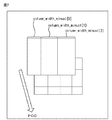
- FIG. 2 is a diagram for explaining the number of values (column_width_minus1) set in the PPS of FIG.
- the PPS corresponding to the picture has three values (column_width_minus1 [0], column_width_minus1 [1], column_width_minus1 [ 2],) is set.
- the value (column_width_minus1) is set in the PPS by the number of divisions in the row direction.
- the value (row_height_minus1) is also set by the number of divisions in the column direction for the same reason.
- the value (column_width_minus1) and value (row_height_minus1) are set when the tile division method is different from the previous picture.
- Non-Patent Document 3 stipulates that the tile width must be 256 pixels or more and the vertical width must be 64 pixels or more as a profile of the HEVC standard.
- the tile has a horizontal width of 256 pixels or more and a vertical width of 64 pixels or more, there are values that are not used as values (column_width_minus1) or values (row_height_minus1). For example, when the horizontal width of the LCU is 64 pixels, the minimum value of the number of LCUs in the tile row direction is 4, so 0 to 2 is not set as the value (column_width_minus1). Therefore, the parameter value indicating the tile size is unnecessarily large and the amount of information is large.
- FIG. 3 is a block diagram illustrating a configuration example of an embodiment of an encoding device to which the present technology is applied.
- the encoding device 10 generates an encoded stream of a frame unit image input as an input signal from the outside.
- the setting unit 11 of the encoding device 10 sets a parameter set such as SPS (Sequence Parameter Set), PPS including a parameter indicating the size of a tile, VUI (Video Usability Information), and the like. To supply.
- SPS Sequence Parameter Set
- PPS Packet Parameter Set
- VUI Video Usability Information
- the encoding unit 12 Based on the parameter set supplied from the setting unit 11, the encoding unit 12 encodes a frame unit image input as an input signal from the outside by the HEVC method for each tile, and generates encoded data. The encoding unit 12 generates an encoded stream from the encoded data and the parameter set, and supplies the encoded stream to the transmission unit 13.
- the transmission unit 13 transmits the encoded stream supplied from the encoding unit 12 to a decoding device to be described later.
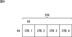
- FIG. 4 is a diagram for explaining a parameter indicating a tile size.
- the encoding apparatus 10 uses a value obtained by subtracting 4 from the number of LCUs in the tile row direction as a parameter indicating the size in the tile row direction.
- a parameter indicating the size in the tile row direction when the horizontal width of the LCU is 64 pixels, there is no value that is not used as a parameter.
- the parameter value is not wasted and the parameter information amount (bit amount) is reduced.
- the high level syntax High Level Syntax
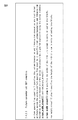
- FIG. 5 is a diagram illustrating an example of the syntax of PPS
- FIG. 6 is a diagram illustrating the contents set in the PPS.
- a value (column_width_minus4) obtained by subtracting 4 from the number of LCUs in the row direction of each tile arranged in the row direction in the corresponding picture is set instead of the value (column_width_minus1). Different from 1 PPS.
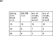
- FIG. 7 is a diagram for explaining the information amount of the value (column_width_minus4).
- the minimum value (column_width_minus4) is 4, and the values not used as parameters are 0 to 3.
- the minimum value of the value (column_width_minus1) is 7, the values not used as parameters are 0 to 6, which is larger than the value (column_width_minus4).
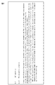
- the value (column_width_minus4) is encoded with an unsigned exponent Golomb code (Unsigned Integer Exp-Golomb CODE) (ue (v)) and set in PPS. Therefore, when the value (column_width_minus4) is X, the bit amount B of the value (column_width_minus4) is expressed by the following equation (1).
- the function Floor (i) in equation (1) is a function for obtaining the maximum integer value equal to or less than i.
- the bit amount B may be small when the value (column_width_minus4) is small.
- the bit amount B is 9 bits.
- the bit amount of the parameter can be reduced compared to the case of using the value (column_width_minus1).
- FIG. 8 and FIG. 9 are diagrams for explaining an example of use of a value (column_width_minus4) in the encoding device 10.
- the encoding unit 12 adds the value (column_width_minus4) included in the PPS and 4 at the time of encoding, and specifies the number of LCUs in the row direction of the tile of the picture corresponding to the PPS.
- VUI flag (tiles_fixes_structure_flag) is set with reference to the value (column_width_minus4).
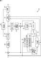
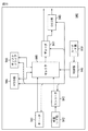
- FIG. 10 is a block diagram illustrating a configuration example of the encoding unit 12 of FIG.
- a / D conversion unit 51 includes an A / D conversion unit 51, a screen rearrangement buffer 52, a division unit 53, tile encoding units 54-1 to 54-N, and a setting unit 55.
- the A / D conversion unit 51 of the encoding unit 12 performs A / D conversion on the frame unit image input as the input signal, and outputs the image to the screen rearrangement buffer 52 for storage.
- the screen rearrangement buffer 52 rearranges the stored frame-by-frame images in the order of encoding in accordance with the GOP (Group of Picture) structure, and supplies the images to the division unit 53.
- GOP Group of Picture
- the dividing unit 53 divides the image supplied from the screen rearranging buffer 52 into N (N is an arbitrary number) tiles based on the PPS supplied from the setting unit 11 in FIG. Specifically, when the equality flag included in the PPS is 0, the dividing unit 53 adds 4 to the value (column_width_minus4) to identify the horizontal width of the tile. Further, the dividing unit 53 adds 1 to the value (row_height_minus1) to specify the vertical width of the tile. Then, the dividing unit 53 divides the image into N tiles based on the horizontal and vertical widths of the tiles.
- the dividing unit 53 supplies N tile images as encoding target images to the tile encoding units 54-1 to 54-N, respectively.
- the tile encoding units 54-1 to 54-N compress and encode the image of the predetermined tile supplied from the dividing unit 53 by the HEVC method independently of the time direction.
- the tile encoding units 54-1 to 54-N supply the encoded data of each tile obtained as a result of compression encoding to the setting unit 55.
- the tile encoding units 54-1 to 54-N are collectively referred to as a tile encoding unit 54 unless it is necessary to distinguish between them.
- the setting unit 55 combines the encoded data of each tile supplied from the tile encoding units 54-1 to 54-N based on the PPS.
- the setting unit 55 generates an encoded stream by adding the parameter set supplied from the setting unit 11 in FIG. 3 to the combined encoded data, and supplies the encoded stream to the transmission unit 13.
- FIG. 11 is a block diagram illustrating a configuration example of the tile encoding unit 54 of FIG.
- the filter processing unit 79, DPB 80, switch 81, intra prediction unit 82, inter prediction unit 83, predicted image selection unit 84, and rate control unit 85 are configured.
- the tile encoding unit 54 receives an image of a predetermined tile as an encoding target image from the dividing unit 53 in FIG. 10 and supplies the image to the arithmetic unit 71, the intra prediction unit 82, and the inter prediction unit 83.
- the calculation unit 71 encodes the encoding target image by calculating a difference between the prediction image supplied from the prediction image selection unit 84 and the encoding target image. Specifically, the computing unit 71 encodes the encoding target image by subtracting the predicted image from the encoding target image. The computing unit 71 outputs the resulting image to the orthogonal transform unit 72 as residual information. When no predicted image is supplied from the predicted image selection unit 84, the calculation unit 71 outputs the encoding target image as it is to the orthogonal transform unit 72 as residual information.
- the orthogonal transform unit 72 performs orthogonal transform on the residual information from the calculation unit 71 and supplies the coefficient obtained as a result of the orthogonal transform to the quantization unit 73.
- the quantization unit 73 quantizes the coefficient supplied from the orthogonal transform unit 72.
- the quantized coefficient is input to the lossless encoding unit 74.
- the lossless encoding unit 74 acquires information indicating the optimal intra prediction mode (hereinafter referred to as intra prediction mode information) from the intra prediction unit 82. Alternatively, the lossless encoding unit 74 acquires information indicating the optimal inter prediction mode (hereinafter referred to as inter prediction mode information), a motion vector, information for specifying a reference image, and the like from the inter prediction unit 83.
- intra prediction mode information information indicating the optimal intra prediction mode
- inter prediction mode information information indicating the optimal inter prediction mode
- motion vector information for specifying a reference image, and the like
- the lossless encoding unit 74 performs variable length encoding (for example, CAVLC (Context-Adaptive Variable Length Coding)), arithmetic encoding (for example, CABAC) on the quantized coefficients supplied from the quantization unit 73. Etc.) is performed.
- variable length encoding for example, CAVLC (Context-Adaptive Variable Length Coding)
- CABAC Arithmetic Coding
- the lossless encoding unit 74 losslessly encodes the intra prediction mode information, the inter prediction mode information, the motion vector, the information for specifying the reference image, and the like to obtain the encoding information related to the encoding.
- the lossless encoding unit 74 supplies the lossless encoded coefficient and the encoding information to the accumulation buffer 75 as encoded data and accumulates them.
- the encoded information may be header information of a losslessly encoded coefficient.
- the accumulation buffer 75 temporarily stores the encoded data supplied from the lossless encoding unit 74. Further, the accumulation buffer 75 supplies the stored encoded data to the setting unit 55 in FIG.
- the quantized coefficient output from the quantization unit 73 is also input to the inverse quantization unit 76, and after inverse quantization, is supplied to the inverse orthogonal transform unit 77.
- the inverse orthogonal transform unit 77 performs inverse orthogonal transform on the coefficient supplied from the inverse quantization unit 76 and supplies residual information obtained as a result to the addition unit 78.
- the addition unit 78 adds the residual information as the decoding target image supplied from the inverse orthogonal transform unit 77 and the prediction image supplied from the prediction image selection unit 84, and locally decodes the tile unit. A decoded image is obtained.
- the adding unit 78 sets the residual information supplied from the inverse orthogonal transform unit 77 as a decoded image in tile units that is locally decoded.
- the adding unit 78 supplies the decoded image of the tile unit decoded locally to the filter processing unit 79 and also supplies the decoded image to the DPB 80 for accumulation.
- the filter processing unit 79 performs filtering as an in-loop filter process on a tile-by-tile basis on the locally decoded decoded image supplied from the adding unit 78.
- the in-loop filter process is a deblock filter process that removes block distortion, a SAO (Sample adaptive offset) process that suppresses ringing, and an ALF (Adaptive loop filter) process that uses class classification or the like.
- the filter processing unit 79 supplies the decoded image in tile units obtained as a result of the in-loop filter processing to the DPB 80 and accumulates it.
- the decoded image in units of tiles accumulated in the DPB 80 is output to the intra prediction unit 82 or the inter prediction unit 83 via the switch 81 as a reference image.
- the intra prediction unit 82 performs intra prediction of all candidate intra prediction modes using the reference image that has not been filtered by the filter processing unit 79 read out from the DPB 80 via the switch 81.
- the intra prediction unit 82 calculates cost function values for all candidate intra prediction modes based on the encoding target image supplied from the dividing unit 53 and the prediction image generated as a result of the intra prediction. (Details will be described later). Then, the intra prediction unit 82 determines the intra prediction mode that minimizes the cost function value as the optimal intra prediction mode, and uses the predicted image generated in the optimal intra prediction mode and the corresponding cost function value as the predicted image. This is supplied to the selector 84. The intra prediction unit 82 supplies the intra prediction mode information to the lossless encoding unit 74 when the prediction image selection unit 84 is notified of the selection of the prediction image generated in the optimal intra prediction mode.
- the cost function value is also called RD (Rate Distortion) cost. It is calculated based on a method of either High Complexity mode or Low Complexity mode as defined by JM (Joint Model) which is reference software in the H.264 / AVC format.
- D is the difference (distortion) between the original image and the decoded image
- R is the amount of generated code including up to the coefficient of orthogonal transform
- ⁇ is the Lagrange multiplier given as a function of the quantization parameter QP.
- D is the difference (distortion) between the original image and the decoded image
- Header_Bit is the header bit for the prediction mode
- QPtoQuant is a function given as a function of the quantization parameter QP.
- the inter prediction unit 83 includes a motion detection unit 83A and a motion compensation processing unit 83B, and performs motion prediction / compensation processing for all candidate inter prediction modes. Specifically, the motion detection unit 83A is filtered by the filter processing unit 79, which is read from the DPB 80 via the switch 81 and has a different time from the image to be encoded supplied from the division unit 53. Using the reference image, motion prediction is performed within the tile of the image to be encoded.
- the motion detection unit 83A uses the filtered reference image of the same tile as the tile of the encoding target image and a frame different from the frame of the encoding target image, and the encoding target image. Thus, motion vectors for all candidate inter prediction modes are detected.
- the motion compensation processing unit 83B performs inter prediction by performing a motion compensation process on the reference image filtered by the filter processing unit 79 based on the motion vector detected by the motion detection unit 83A, thereby obtaining a predicted image. Generate.
- the inter prediction unit 83 calculates cost function values for all candidate inter prediction modes based on the encoding target image and the prediction image, and the inter prediction mode in which the cost function value is minimized. To the optimum inter measurement mode. Then, the inter prediction unit 83 supplies the cost function value of the optimal inter prediction mode and the corresponding prediction image to the prediction image selection unit 84. In addition, when the prediction image selection unit 84 is notified of selection of a prediction image generated in the optimal inter prediction mode, the inter prediction unit 83 receives inter prediction mode information, a corresponding motion vector, information for specifying a reference image, and the like. The result is output to the lossless encoding unit 74.
- the predicted image selection unit 84 selects the smaller one of the optimal intra prediction mode and the optimal inter prediction mode with the corresponding cost function value. Determine the optimal prediction mode. Then, the predicted image selection unit 84 supplies the predicted image in the optimal prediction mode to the calculation unit 71 and the addition unit 78. Further, the predicted image selection unit 84 notifies the intra prediction unit 82 or the inter prediction unit 83 of selection of the predicted image in the optimal prediction mode.
- the rate control unit 85 controls the rate of the quantization operation of the quantization unit 73 based on the encoded data stored in the storage buffer 75 so that overflow or underflow does not occur.
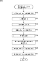
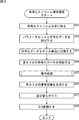
- FIG. 12 is a flowchart illustrating an encoded stream generation process of the encoding device 10 of FIG.
- the setting unit 11 of the encoding device 10 sets a parameter set such as PPS and VUI including SPS and value (column_width_minus4), and supplies the parameter set to the encoding unit 12.
- step S11 the A / D conversion unit 51 (FIG. 10) of the encoding unit 12 performs A / D conversion on the frame unit image input as the input signal, and outputs and stores it in the screen rearrangement buffer 52.
- step S12 the screen rearrangement buffer 52 rearranges the stored frame-by-frame images in the order of encoding according to the GOP structure, and supplies the images to the division unit 53.
- step S13 the dividing unit 53 divides the image supplied from the screen rearranging buffer 52 into N tiles based on the PPS supplied from the setting unit 11.
- the dividing unit 53 supplies N tile images to the tile coding units 54-1 to 54-N as coding unit images, respectively.
- step S14 the tile encoding unit 54 performs an encoding process in which the image of the predetermined tile supplied from the dividing unit 53 is compression-encoded by the HEVC method independently of the time direction. Details of the encoding process will be described with reference to FIGS. 13 and 14 to be described later.
- step S15 the setting unit 55 synthesizes the encoded data of each tile supplied from the tile encoding units 54-1 to 54-N based on the PPS.
- step S16 the setting unit 55 generates an encoded stream by adding a parameter set to the combined encoded data, and supplies the encoded stream to the transmission unit 13 in FIG.
- step S17 the transmission unit 13 transmits the encoded stream supplied from the setting unit 55 to a decoding device to be described later, and ends the process.
- FIG. 13 and 14 are flowcharts for explaining the encoding process in step S14 of FIG. This encoding process is performed, for example, in units of CUs.
- step S30 the intra prediction unit 82 performs intra prediction in all candidate intra prediction modes using, as a reference image, an unfiltered image stored in the DPB 80 and having the same tile as the image to be encoded. Perform intra prediction processing. At this time, the intra prediction unit 82 calculates the cost for all candidate intra prediction modes based on the encoding target image supplied from the dividing unit 53 and the prediction image generated as a result of the intra prediction process. Calculate the function value. Then, the intra prediction unit 82 determines the intra prediction mode that minimizes the cost function value as the optimal intra prediction mode, and selects the prediction image generated in the optimal intra prediction mode and the corresponding cost function value as the prediction image selection. To the unit 84.
- the inter prediction unit 83 uses the filtered image of the same tile as the encoding target image stored in the DPB 80 as a reference image, and performs motion prediction and motion in all candidate inter prediction mode tiles. Perform compensation processing. At this time, the inter prediction unit 83 determines the cost for all candidate inter prediction modes based on the encoding target image supplied from the dividing unit 53 and the prediction image generated as a result of the motion compensation process. Calculate the function value. Then, the inter prediction unit 83 determines the inter prediction mode that minimizes the cost function value as the optimal inter prediction mode, and selects the predicted image generated in the optimal inter prediction mode and the corresponding cost function value as the predicted image selection. To the unit 84.
- step S31 the predicted image selection unit 84, based on the cost function values supplied from the intra prediction unit 82 and the inter prediction unit 83 by the process of step S30, cost functions of the optimal intra prediction mode and the optimal inter prediction mode. The one with the smallest value is determined as the optimum prediction mode. Then, the predicted image selection unit 84 supplies the predicted image in the optimal prediction mode to the calculation unit 71 and the addition unit 78.
- step S32 the predicted image selection unit 84 determines whether or not the optimal prediction mode is the optimal inter prediction mode.
- the predicted image selection unit 84 notifies the inter prediction unit 83 of the selection of the predicted image generated in the optimal inter prediction mode.
- the inter prediction unit 83 outputs the inter prediction mode information, the corresponding motion vector, and information for specifying the reference image to the lossless encoding unit 74.
- step S33 the lossless encoding unit 74 performs lossless encoding on the inter prediction mode information supplied from the inter prediction unit 83, information for specifying a reference image, and a motion vector, and encodes the resulting information as encoded information. And Then, the process proceeds to step S35.
- step S32 when it is determined in step S32 that the optimum prediction mode is not the optimum inter prediction mode, that is, when the optimum prediction mode is the optimum intra prediction mode, the predicted image selection unit 84 performs the prediction generated in the optimum intra prediction mode.
- the intra prediction unit 82 is notified of the image selection. Thereby, the intra prediction unit 82 supplies the intra prediction mode information to the lossless encoding unit 74.
- step S34 the lossless encoding unit 74 performs lossless encoding on the intra prediction mode information supplied from the intra prediction unit 82, and uses the resulting information as encoded information. Then, the process proceeds to step S35.
- step S35 the calculation unit 71 subtracts the prediction image supplied from the prediction image selection unit 84 from the image to be encoded supplied from the division unit 53.
- the computing unit 71 outputs the image obtained as a result of the subtraction to the orthogonal transform unit 72 as residual information.
- step S 36 the orthogonal transform unit 72 performs orthogonal transform on the residual information from the calculation unit 71 and supplies the coefficient obtained as a result to the quantization unit 73.
- step S37 the quantization unit 73 quantizes the coefficient supplied from the orthogonal transform unit 72.
- the quantized coefficient is input to the lossless encoding unit 74 and the inverse quantization unit 76.
- step S38 the lossless encoding unit 74 performs lossless encoding on the quantized coefficient supplied from the quantization unit 73.
- the lossless encoding unit 74 generates encoded data from the information obtained as a result and the encoded information generated by the process of step S33 or S34.
- step S39 of FIG. 14 the lossless encoding unit 74 supplies the encoded data to the accumulation buffer 75 and accumulates it.
- step S40 the accumulation buffer 75 outputs the accumulated encoded data to the setting unit 55 (FIG. 10).
- step S41 the inverse quantization unit 76 inversely quantizes the quantized coefficient supplied from the quantization unit 73.
- step S42 the inverse orthogonal transform unit 77 performs inverse orthogonal transform on the coefficient supplied from the inverse quantization unit 76, and supplies the residual information obtained as a result to the addition unit 78.
- step S43 the adding unit 78 adds the residual information supplied from the inverse orthogonal transform unit 77 and the predicted image supplied from the predicted image selecting unit 84, and outputs the decoded image in units of tiles that are locally decoded. obtain.
- the adding unit 78 supplies the obtained decoded image in tile units to the filter processing unit 79 and also supplies it to the DPB 80.
- step S44 the filter processing unit 79 performs filtering as an in-loop filter process on a tile-by-tile basis on the locally decoded tile-unit decoded image supplied from the addition unit 78.
- the filter processing unit 79 supplies the decoded image of the tile unit obtained as a result to the DPB 80.
- step S45 the DPB 80 stores the decoded images in tile units before and after filtering. Specifically, the DPB 80 stores the decoded image in units of tiles supplied from the adding unit 78 and the decoded image in units of tiles supplied from the filter processing unit 79. The decoded image in units of tiles accumulated in the DPB 80 is output to the intra prediction unit 82 or the inter prediction unit 83 via the switch 81 as a reference image. And a process returns to step S14 of FIG. 12, and progresses to step S15.
- the encoding apparatus 10 transmits the value (column_width_minus4) as a parameter indicating the size of the tile in the row direction, the amount of parameter information can be reduced compared to the case of transmitting the value (column_width_minus1). Can do.
- the encoding unit 12 includes the N tile encoding units 54 that encode the images of the tiles, but may include one encoding unit.
- the encoding unit has a DPB that stores the decoded image for each tile, and encodes the image for each tile in the raster scan order.
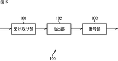
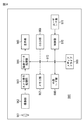
- FIG. 15 is a block diagram illustrating a configuration example of an embodiment of a decoding device to which the present technology is applied, which decodes an encoded stream transmitted from the encoding device 10 of FIG.
- the 15 includes a receiving unit 101, an extracting unit 102, and a decoding unit 103.
- the receiving unit 101 of the decoding device 100 receives the encoded stream transmitted from the encoding device 10 and supplies it to the extracting unit 102.
- the extraction unit 102 extracts encoded data and parameter sets from the encoded stream supplied from the receiving unit 101 and supplies the extracted data and parameter set to the decoding unit 103.
- the decoding unit 103 Based on the parameter set supplied from the extraction unit 102, the decoding unit 103 decodes the encoded data for each tile using the HEVC method, and generates an image in units of frames. The decoding unit 103 outputs the generated frame unit image.
- FIG. 16 is a block diagram illustrating a configuration example of the decoding unit 103 in FIG.
- 16 includes a dividing unit 121, tile decoding units 122-1 to 122-N, a screen rearrangement buffer 123, and a D / A conversion unit 124.
- the dividing unit 121 of the decoding unit 103 divides the encoded data into tile units based on the PPS supplied from the extracting unit 102 of FIG. Specifically, the dividing unit 121 functions as a control unit, and specifies the horizontal and vertical widths of tiles based on the PPS, similarly to the dividing unit 53 in FIG. Then, the dividing unit 121 divides the encoded data into tile units based on the horizontal and vertical widths of the tiles.
- the dividing unit 121 supplies the encoded data of N tiles obtained as a result to the tile decoding units 122-1 to 122-N for each tile, and needs the parameter set supplied from the receiving unit 101. Accordingly, the data is supplied to the tile decoding units 122-1 to 122-N. Thereby, the dividing unit 121 controls the decoding of the tile decoding units 122-1 to 122-N.
- the tile decoding units 122-1 to 122-N each refer to the parameter set supplied from the dividing unit 121 and decode the encoded data of the predetermined tile supplied from the dividing unit 121 by the HEVC method. That is, the tile decoding units 122-1 to 122-N refer to the parameter set and decode the encoded data independently for each tile in the time direction.
- the tile decoding units 122-1 to 122-N supply the decoded image obtained as a result of decoding to the screen rearrangement buffer 123.
- the tile decoding units 122-1 to 122-N are collectively referred to as a tile decoding unit 122 unless it is necessary to distinguish between them.
- the screen rearrangement buffer 123 Based on the PPS supplied from the extraction unit 102, the screen rearrangement buffer 123 arranges the decoded images of the tiles supplied from the tile decoding units 122-1 to 122-N and stores them in units of frames. . The screen rearrangement buffer 123 rearranges the stored frame-by-frame images for encoding in the original display order and supplies them to the D / A conversion unit 124.
- the D / A conversion unit 124 D / A converts the frame unit image supplied from the screen rearrangement buffer 123 and outputs it as an output signal.
- FIG. 17 is a block diagram illustrating a configuration example of the tile decoding unit 122 of FIG.
- the 17 includes a storage buffer 141, a lossless decoding unit 142, an inverse quantization unit 143, an inverse orthogonal transform unit 144, an addition unit 145, a filter processing unit 146, a DPB 147, a switch 148, an intra prediction unit 149, a motion
- the compensation processing unit 150 and the switch 151 are included.
- the accumulation buffer 141 of the tile decoding unit 122 receives and accumulates encoded data of a predetermined tile supplied from the dividing unit 121 of FIG.
- the accumulation buffer 141 supplies the accumulated encoded data to the lossless decoding unit 142.
- the lossless decoding unit 142 obtains quantized coefficients and encoded information by performing lossless decoding such as variable length decoding and arithmetic decoding on the encoded data from the accumulation buffer 141.
- the lossless decoding unit 142 supplies the quantized coefficient to the inverse quantization unit 143.
- the lossless decoding unit 142 supplies intra prediction mode information as encoded information to the intra prediction unit 149. Further, the lossless decoding unit 142 supplies the motion compensation processing unit 150 with a motion vector as encoded information, information for specifying a reference image, inter prediction mode information, and the like. Further, the lossless decoding unit 142 supplies intra prediction mode information or inter prediction mode information to the switch 151.
- the inverse quantization unit 143, the inverse orthogonal transform unit 144, the addition unit 145, the filter processing unit 146, the DPB 147, the switch 148, the intra prediction unit 149, and the motion compensation processing unit 150 are the inverse quantization unit 76 of FIG.
- the same processing as that performed by the orthogonal transform unit 77, the addition unit 78, the filter processing unit 79, the DPB 80, the switch 81, the intra prediction unit 82, and the inter prediction unit 83 is performed, whereby the image is decoded.
- the inverse quantization unit 143 inversely quantizes the quantized coefficient from the lossless decoding unit 142 and supplies the resulting coefficient to the inverse orthogonal transform unit 144.
- the inverse orthogonal transform unit 144 performs inverse orthogonal transform on the coefficient from the inverse quantization unit 143 and supplies the residual information obtained as a result to the addition unit 145.
- the addition unit 145 performs decoding by adding the residual information as the decoding target image supplied from the inverse orthogonal transform unit 144 and the prediction image supplied from the switch 151.
- the adder 145 supplies the decoded image obtained as a result of decoding to the filter processor 146 and also supplies it to the DPB 147.
- the adding unit 145 supplies the image that is residual information supplied from the inverse orthogonal transform unit 144 as a decoded image to the filter processing unit 146 and also supplies it to the DPB 147. To accumulate.
- the filter processing unit 146 Based on the deblock filter information included in the SPS and PPS supplied from the dividing unit 121, the filter processing unit 146 performs filtering as an in-loop filter process in units of tiles on the decoded image supplied from the adding unit 145. Is applied to remove block distortion.
- the filter processing unit 146 supplies the decoded image obtained as a result to the DPB 147 for storage, and also supplies it to the screen rearrangement buffer 123 of FIG.
- the decoded image of the predetermined tile accumulated in the DPB 147 is read out as a reference image via the switch 148 and supplied to the motion compensation processing unit 150 or the intra prediction unit 149.
- the intra prediction unit 149 uses the reference image of the same tile as the image to be decoded, which has not been filtered by the filter processing unit 146, read from the DPB 147 via the switch 148, and is the optimum indicated by the intra prediction mode information. Performs intra prediction in intra prediction mode.
- the intra prediction unit 149 supplies the prediction image generated as a result to the switch 151.
- the motion compensation processing unit 150 uses the DPB 147 via the switch 148 to identify the same image as the decoding target image in a different frame from the decoding target image.
- the reference image filtered by the filter processing unit 146 is read out. That is, the motion compensation processing unit 150 reads the reference image in the collocated tile from the DPB 147 based on the information for specifying the reference image.
- the motion compensation processing unit 150 performs inter prediction in the optimal inter prediction mode by performing motion compensation processing in the optimal inter prediction mode indicated by the inter prediction mode information on the reference image based on the motion vector.
- the motion compensation processing unit 150 supplies the predicted image generated as a result to the switch 151.
- the switch 151 supplies the prediction image supplied from the intra prediction unit 149 to the adding unit 145.
- the switch 151 supplies the prediction image supplied from the motion compensation processing unit 150 to the adding unit 145.
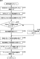
- FIG. 18 is a flowchart illustrating an encoded stream decoding process of decoding apparatus 100 in FIG.
- the reception unit 101 of the decoding device 100 receives the encoded stream transmitted from the encoding device 10 and supplies the encoded stream to the extraction unit 102.
- step S62 the extraction unit 102 extracts a parameter set and encoded data from the encoded stream, and supplies the extracted parameter set and encoded data to the decoding unit 103.
- step S63 the dividing unit 121 (FIG. 16) of the decoding unit 103 divides the encoded data into tile units based on the PPS supplied from the extracting unit 102.
- step S64 the dividing unit 121 supplies the encoded data of each of the N divided tiles to the tile decoding units 122-1 to 122-N, respectively.
- the dividing unit 121 supplies the parameter set supplied from the extracting unit 102 to the tile decoding unit 122-N.
- step S65 the tile decoding unit 122 refers to the parameter set supplied from the dividing unit 121, and performs a decoding process of decoding the encoded data of the predetermined tile supplied from the dividing unit 121 by the HEVC method. Details of this decoding process will be described with reference to FIG.
- step S66 the screen rearrangement buffer 123 combines the decoded images of the tiles supplied from the tile decoding units 122-1 to 122-N by storing them in units of frames based on the PPS.
- step S67 the screen rearrangement buffer 123 rearranges the stored frame-by-frame images for encoding in the original display order, and supplies them to the D / A conversion unit 124.
- step S68 the D / A converter 124 performs D / A conversion on the frame unit image supplied from the screen rearrangement buffer 123, and outputs it as an output signal.
- FIG. 19 is a flowchart for explaining the decoding process in step S65 of FIG.
- step S100 of FIG. 19 the accumulation buffer 141 (FIG. 17) of the tile decoding unit 122 receives and accumulates encoded data of a predetermined tile from the dividing unit 121 of FIG.
- the accumulation buffer 141 supplies the accumulated encoded data to the lossless decoding unit 142. Note that the processes in steps S101 to S109 below are performed, for example, in units of CUs.
- step S101 the lossless decoding unit 142 losslessly decodes the encoded data from the accumulation buffer 141, and obtains quantized coefficients and encoded information.
- the lossless decoding unit 142 supplies the quantized coefficient to the inverse quantization unit 143.
- the lossless decoding unit 142 supplies intra prediction mode information as encoded information to the intra prediction unit 149 and the switch 151.
- the lossless decoding unit 142 supplies the motion compensation processing unit 150 with a motion vector as encoded information, information for specifying a reference image, inter prediction mode information, and the like. Further, the lossless decoding unit 142 supplies inter prediction mode information to the switch 151.
- step S102 the inverse quantization unit 143 inversely quantizes the quantized coefficient from the lossless decoding unit 142, and supplies the coefficient obtained as a result to the inverse orthogonal transform unit 144.
- step S103 the motion compensation processing unit 150 determines whether or not the inter prediction mode information is supplied from the lossless decoding unit 142. If it is determined in step S103 that the inter prediction mode information has been supplied, the process proceeds to step S104.
- step S ⁇ b> 104 the motion compensation processing unit 150 performs the decoding that is filtered by the filter processing unit 146 based on the motion vector, the inter prediction mode information, and the information for specifying the reference image supplied from the lossless decoding unit 142. Motion compensation processing is performed using a reference image having the same tile as the target image. The motion compensation processing unit 150 supplies the predicted image generated as a result to the adding unit 145 via the switch 151, and the process proceeds to step S106.
- step S103 when it is determined in step S103 that the inter prediction mode information is not supplied, that is, when the intra prediction mode information is supplied to the intra prediction unit 149, the process proceeds to step S105.
- step S105 the intra prediction unit 149 uses the reference image of the same tile as the image to be decoded that has not been filtered by the filter processing unit 146 read from the DPB 147 via the switch 148, and uses the intra prediction mode information. Intra prediction processing is performed to perform intra prediction.
- the intra prediction unit 149 supplies the prediction image generated as a result of the intra prediction process to the adding unit 145 via the switch 151, and the process proceeds to step S106.
- step S106 the inverse orthogonal transform unit 144 performs inverse orthogonal transform on the coefficient from the inverse quantization unit 143, and supplies residual information obtained as a result to the addition unit 145.
- step S107 the adding unit 145 performs decoding by adding the residual information as the decoding target image supplied from the inverse orthogonal transform unit 144 and the prediction image supplied from the switch 151.
- the adder 145 supplies the decoded image obtained as a result to the filter processor 146 and also supplies it to the DPB 147.
- step S108 the filter processing unit 146 performs an in-loop filter on the decoded image supplied from the adding unit 145 on a tile basis based on the deblock filter information included in the SPS and PPS supplied from the dividing unit 121. Filtering is performed as a process.
- the filter processing unit 146 supplies the filtered decoded image to the DPB 147 and the screen rearrangement buffer 123 (FIG. 16).
- step S109 the DPB 147 accumulates the decoded image before filtering supplied from the adding unit 145 and the decoded image after filtering supplied from the filter processing unit 146.
- the decoded image stored in the DPB 147 is supplied as a reference image to the motion compensation processing unit 150 or the intra prediction unit 149 via the switch 148. Then, the process returns to step S65 in FIG. 18 and proceeds to step S66.
- the decoding unit 103 has N tile decoding units 122 that decode the image of each tile, but may have one tile decoding unit 122.
- the decoding unit has a DPB that stores the decoded image for each tile, and decodes the image for each tile in the raster scan order.
- the optimal value (column_width_minus4) is used as the parameter indicating the size of the tile in the row direction when the LCU size is the maximum of 64 ⁇ 64 pixels, but the number of LCUs in the tile row direction
- the value to be subtracted from may be set according to the size of the LCU.
- the parameter indicating the size of the tile in the row direction is a value obtained by subtracting the number of LCUs corresponding to 256 pixels, which is the minimum value of the tile width, from the number of LCUs in the tile row direction (hereinafter referred to as parameter subtraction). Value). That is, the parameter is set so that the minimum value of the parameter becomes 0 according to the ratio of the minimum value of the horizontal width of the tile and the size of the LCU.
- the LCU size is 64 x 64 pixels
- the LCU size is 32 x 32 pixels.
- the LCU size is 16 ⁇ 16 pixels
- the encoding device and the decoding device determine the parameter subtraction value based on the minimum value of the LCU size and the tile size included in the SPS. Then, the encoding device and the decoding device add the parameter indicating the size in the row direction of the tile included in the PPS and the parameter subtraction value, and specify the tile width.
- the parameter indicating the size in the column direction of the tile is the minimum value of the LCU size and the vertical width of the tile from the number of LCUs in the column direction of the tile, as in the parameter indicating the size in the row direction of the tile.
- a value obtained by subtracting a value set based on 64 can be used.
- a parameter indicating the size of the tile in the column direction a value obtained by subtracting the number of LCUs corresponding to 64 pixels which is the minimum value of the vertical length of the tile from the number of LCUs in the column direction of the tile is used. That is, the parameter is set so that the minimum value of the parameter becomes 0 according to the ratio between the minimum value of the vertical width of the tile and the size of the LCU.
- the LCU size is 64 ⁇ 64 pixels
- the LCU size is 32 ⁇ 32 pixels.
- the LCU size is 16 ⁇ 16 pixels
- the parameter indicating the tile size is set to PPS in units of pictures, but may be set to SPS in units of sequences. This parameter can also be set in a predetermined unit in a parameter set other than PPS and SPS.
- the decoding apparatus can generate a one-viewpoint image as a 2D image by decoding the encoded data of one tile.
- the series of processes described above can be executed by hardware or can be executed by software.
- a program constituting the software is installed in the computer.
- the computer includes, for example, a general-purpose personal computer capable of executing various functions by installing various programs by installing a computer incorporated in dedicated hardware.
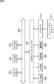
- FIG. 20 is a block diagram showing an example of the hardware configuration of a computer that executes the above-described series of processing by a program.
- a CPU Central Processing Unit
- ROM Read Only Memory
- RAM Random Access Memory
- An input / output interface 205 is further connected to the bus 204.
- An input unit 206, an output unit 207, a storage unit 208, a communication unit 209, and a drive 210 are connected to the input / output interface 205.
- the input unit 206 includes a keyboard, a mouse, a microphone, and the like.
- the output unit 207 includes a display, a speaker, and the like.
- the storage unit 208 includes a hard disk, a nonvolatile memory, and the like.
- the communication unit 209 includes a network interface and the like.
- the drive 210 drives a removable medium 211 such as a magnetic disk, an optical disk, a magneto-optical disk, or a semiconductor memory.
- the CPU 201 loads, for example, the program stored in the storage unit 208 to the RAM 203 via the input / output interface 205 and the bus 204 and executes the program. Is performed.
- the program executed by the computer (CPU 201) can be provided by being recorded in the removable medium 211 as a package medium or the like, for example.
- the program can be provided via a wired or wireless transmission medium such as a local area network, the Internet, or digital satellite broadcasting.
- the program can be installed in the storage unit 208 via the input / output interface 205 by attaching the removable medium 211 to the drive 210.
- the program can be received by the communication unit 209 via a wired or wireless transmission medium and installed in the storage unit 208.
- the program can be installed in advance in the ROM 202 or the storage unit 208.
- the program executed by the computer may be a program that is processed in time series in the order described in this specification, or in parallel or at a necessary timing such as when a call is made. It may be a program for processing.
- FIG. 21 illustrates a schematic configuration of a television apparatus to which the present technology is applied.
- the television apparatus 900 includes an antenna 901, a tuner 902, a demultiplexer 903, a decoder 904, a video signal processing unit 905, a display unit 906, an audio signal processing unit 907, a speaker 908, and an external interface unit 909. Furthermore, the television apparatus 900 includes a control unit 910, a user interface unit 911, and the like.
- the tuner 902 selects a desired channel from the broadcast wave signal received by the antenna 901, demodulates it, and outputs the obtained encoded bit stream to the demultiplexer 903.
- the demultiplexer 903 extracts video and audio packets of the program to be viewed from the encoded bit stream, and outputs the extracted packet data to the decoder 904. Further, the demultiplexer 903 supplies a packet of data such as EPG (Electronic Program Guide) to the control unit 910. If scrambling is being performed, descrambling is performed by a demultiplexer or the like.
- EPG Electronic Program Guide
- the decoder 904 performs packet decoding processing, and outputs video data generated by the decoding processing to the video signal processing unit 905 and audio data to the audio signal processing unit 907.
- the video signal processing unit 905 performs noise removal, video processing according to user settings, and the like on the video data.
- the video signal processing unit 905 generates video data of a program to be displayed on the display unit 906, image data by processing based on an application supplied via a network, and the like.
- the video signal processing unit 905 generates video data for displaying a menu screen for selecting an item and the like, and superimposes the video data on the video data of the program.
- the video signal processing unit 905 generates a drive signal based on the video data generated in this way, and drives the display unit 906.
- the display unit 906 drives a display device (for example, a liquid crystal display element or the like) based on a drive signal from the video signal processing unit 905 to display a program video or the like.
- a display device for example, a liquid crystal display element or the like
- the audio signal processing unit 907 performs predetermined processing such as noise removal on the audio data, performs D / A conversion processing and amplification processing on the processed audio data, and outputs the audio data to the speaker 908.
- the external interface unit 909 is an interface for connecting to an external device or a network, and transmits and receives data such as video data and audio data.
- a user interface unit 911 is connected to the control unit 910.
- the user interface unit 911 includes an operation switch, a remote control signal receiving unit, and the like, and supplies an operation signal corresponding to a user operation to the control unit 910.
- the control unit 910 is configured using a CPU (Central Processing Unit), a memory, and the like.
- the memory stores a program executed by the CPU, various data necessary for the CPU to perform processing, EPG data, data acquired via a network, and the like.
- the program stored in the memory is read and executed by the CPU at a predetermined timing such as when the television device 900 is activated.
- the CPU executes each program to control each unit so that the television device 900 operates in accordance with the user operation.
- the television device 900 includes a bus 912 for connecting the tuner 902, the demultiplexer 903, the video signal processing unit 905, the audio signal processing unit 907, the external interface unit 909, and the control unit 910.
- the decoder 904 is provided with the function of the decoding apparatus (decoding method) of the present application. Therefore, the encoded data can be decoded using the parameter indicating the size of the tile whose information amount is reduced.
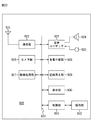
- FIG. 22 illustrates a schematic configuration of a mobile phone to which the present technology is applied.
- the cellular phone 920 includes a communication unit 922, an audio codec 923, a camera unit 926, an image processing unit 927, a demultiplexing unit 928, a recording / reproducing unit 929, a display unit 930, and a control unit 931. These are connected to each other via a bus 933.
- an antenna 921 is connected to the communication unit 922, and a speaker 924 and a microphone 925 are connected to the audio codec 923. Further, an operation unit 932 is connected to the control unit 931.
- the mobile phone 920 performs various operations such as transmission / reception of voice signals, transmission / reception of e-mail and image data, image shooting, and data recording in various modes such as a voice call mode and a data communication mode.
- the voice signal generated by the microphone 925 is converted into voice data and compressed by the voice codec 923 and supplied to the communication unit 922.
- the communication unit 922 performs audio data modulation processing, frequency conversion processing, and the like to generate a transmission signal.
- the communication unit 922 supplies a transmission signal to the antenna 921 and transmits it to a base station (not shown).
- the communication unit 922 performs amplification, frequency conversion processing, demodulation processing, and the like of the reception signal received by the antenna 921, and supplies the obtained audio data to the audio codec 923.
- the audio codec 923 performs data expansion of the audio data and conversion to an analog audio signal and outputs the result to the speaker 924.
- the control unit 931 receives character data input by operating the operation unit 932 and displays the input characters on the display unit 930.
- the control unit 931 generates mail data based on a user instruction or the like in the operation unit 932 and supplies the mail data to the communication unit 922.
- the communication unit 922 performs mail data modulation processing, frequency conversion processing, and the like, and transmits the obtained transmission signal from the antenna 921.
- the communication unit 922 performs amplification, frequency conversion processing, demodulation processing, and the like of the reception signal received by the antenna 921, and restores mail data. This mail data is supplied to the display unit 930 to display the mail contents.
- the mobile phone 920 can also store the received mail data in a storage medium by the recording / playback unit 929.
- the storage medium is any rewritable storage medium.
- the storage medium is a removable medium such as a semiconductor memory such as a RAM or a built-in flash memory, a hard disk, a magnetic disk, a magneto-optical disk, an optical disk, a USB memory, or a memory card.
- the image data generated by the camera unit 926 is supplied to the image processing unit 927.
- the image processing unit 927 performs encoding processing of image data and generates encoded data.
- the demultiplexing unit 928 multiplexes the encoded data generated by the image processing unit 927 and the audio data supplied from the audio codec 923 by a predetermined method, and supplies the multiplexed data to the communication unit 922.
- the communication unit 922 performs modulation processing and frequency conversion processing of multiplexed data, and transmits the obtained transmission signal from the antenna 921.
- the communication unit 922 performs amplification, frequency conversion processing, demodulation processing, and the like of the reception signal received by the antenna 921, and restores multiplexed data. This multiplexed data is supplied to the demultiplexing unit 928.
- the demultiplexing unit 928 performs demultiplexing of the multiplexed data, and supplies the encoded data to the image processing unit 927 and the audio data to the audio codec 923.
- the image processing unit 927 performs a decoding process on the encoded data to generate image data.
- the image data is supplied to the display unit 930 and the received image is displayed.
- the audio codec 923 converts the audio data into an analog audio signal, supplies the analog audio signal to the speaker 924, and outputs the received audio.
- the image processing unit 927 is provided with the functions of the encoding device and the decoding device (encoding method and decoding method) of the present application. For this reason, it is possible to reduce the information amount of the parameter indicating the tile size. Also, the encoded data can be decoded using a parameter indicating the size of the tile whose information amount is reduced.
- FIG. 23 illustrates a schematic configuration of a recording / reproducing apparatus to which the present technology is applied.
- the recording / reproducing apparatus 940 records, for example, audio data and video data of a received broadcast program on a recording medium, and provides the recorded data to the user at a timing according to a user instruction.
- the recording / reproducing device 940 can also acquire audio data and video data from another device, for example, and record them on a recording medium. Further, the recording / reproducing apparatus 940 decodes and outputs the audio data and video data recorded on the recording medium, thereby enabling image display and audio output on the monitor apparatus or the like.
- the recording / reproducing apparatus 940 includes a tuner 941, an external interface unit 942, an encoder 943, an HDD (Hard Disk Drive) unit 944, a disk drive 945, a selector 946, a decoder 947, an OSD (On-Screen Display) unit 948, a control unit 949, A user interface unit 950 is included.
- Tuner 941 selects a desired channel from a broadcast signal received by an antenna (not shown).
- the tuner 941 outputs an encoded bit stream obtained by demodulating the received signal of a desired channel to the selector 946.
- the external interface unit 942 includes at least one of an IEEE 1394 interface, a network interface unit, a USB interface, a flash memory interface, and the like.
- the external interface unit 942 is an interface for connecting to an external device, a network, a memory card, and the like, and receives data such as video data and audio data to be recorded.
- the encoder 943 performs encoding by a predetermined method when the video data and audio data supplied from the external interface unit 942 are not encoded, and outputs an encoded bit stream to the selector 946.
- the HDD unit 944 records content data such as video and audio, various programs, and other data on a built-in hard disk, and reads them from the hard disk during playback.
- the disk drive 945 records and reproduces signals with respect to the mounted optical disk.
- An optical disk such as a DVD disk (DVD-Video, DVD-RAM, DVD-R, DVD-RW, DVD + R, DVD + RW, etc.), a Blu-ray (registered trademark) disk, or the like.
- the selector 946 selects one of the encoded bit streams from the tuner 941 or the encoder 943 and supplies it to either the HDD unit 944 or the disk drive 945 when recording video or audio. Further, the selector 946 supplies the encoded bit stream output from the HDD unit 944 or the disk drive 945 to the decoder 947 at the time of reproduction of video and audio.
- the decoder 947 performs a decoding process on the encoded bit stream.
- the decoder 947 supplies the video data generated by performing the decoding process to the OSD unit 948.
- the decoder 947 outputs audio data generated by performing the decoding process.
- the OSD unit 948 generates video data for displaying a menu screen for selecting an item and the like, and superimposes it on the video data output from the decoder 947 and outputs the video data.
- a user interface unit 950 is connected to the control unit 949.
- the user interface unit 950 includes an operation switch, a remote control signal receiving unit, and the like, and supplies an operation signal corresponding to a user operation to the control unit 949.
- the control unit 949 is configured using a CPU, a memory, and the like.
- the memory stores programs executed by the CPU and various data necessary for the CPU to perform processing.
- the program stored in the memory is read and executed by the CPU at a predetermined timing such as when the recording / reproducing apparatus 940 is activated.
- the CPU executes the program to control each unit so that the recording / reproducing device 940 operates according to the user operation.
- the decoder 947 is provided with the function of the decoding apparatus (decoding method) of the present application. Therefore, the encoded data can be decoded using the parameter indicating the size of the tile whose information amount is reduced.
- FIG. 24 illustrates a schematic configuration of an imaging apparatus to which the present technology is applied.
- the imaging device 960 images a subject, displays an image of the subject on a display unit, and records it on a recording medium as image data.
- the imaging device 960 includes an optical block 961, an imaging unit 962, a camera signal processing unit 963, an image data processing unit 964, a display unit 965, an external interface unit 966, a memory unit 967, a media drive 968, an OSD unit 969, and a control unit 970. Have. In addition, a user interface unit 971 is connected to the control unit 970. Furthermore, the image data processing unit 964, the external interface unit 966, the memory unit 967, the media drive 968, the OSD unit 969, the control unit 970, and the like are connected via a bus 972.
- the optical block 961 is configured using a focus lens, a diaphragm mechanism, and the like.
- the optical block 961 forms an optical image of the subject on the imaging surface of the imaging unit 962.
- the imaging unit 962 is configured using a CCD or CMOS image sensor, generates an electrical signal corresponding to the optical image by photoelectric conversion, and supplies the electrical signal to the camera signal processing unit 963.
- the camera signal processing unit 963 performs various camera signal processing such as knee correction, gamma correction, and color correction on the electrical signal supplied from the imaging unit 962.
- the camera signal processing unit 963 supplies the image data after the camera signal processing to the image data processing unit 964.
- the image data processing unit 964 performs an encoding process on the image data supplied from the camera signal processing unit 963.
- the image data processing unit 964 supplies the encoded data generated by performing the encoding process to the external interface unit 966 and the media drive 968. Further, the image data processing unit 964 performs a decoding process on the encoded data supplied from the external interface unit 966 and the media drive 968.
- the image data processing unit 964 supplies the image data generated by performing the decoding process to the display unit 965. Further, the image data processing unit 964 superimposes the processing for supplying the image data supplied from the camera signal processing unit 963 to the display unit 965 and the display data acquired from the OSD unit 969 on the image data. To supply.
- the OSD unit 969 generates display data such as a menu screen and icons made up of symbols, characters, or figures and outputs them to the image data processing unit 964.
- the external interface unit 966 includes, for example, a USB input / output terminal, and is connected to a printer when printing an image.
- a drive is connected to the external interface unit 966 as necessary, a removable medium such as a magnetic disk or an optical disk is appropriately mounted, and a computer program read from them is installed as necessary.
- the external interface unit 966 has a network interface connected to a predetermined network such as a LAN or the Internet.
- the control unit 970 reads the encoded data from the memory unit 967 in accordance with an instruction from the user interface unit 971, and supplies the encoded data to the other device connected via the network from the external interface unit 966. it can.
- the control unit 970 may acquire encoded data and image data supplied from another device via the network via the external interface unit 966 and supply the acquired data to the image data processing unit 964. it can.
- any readable / writable removable medium such as a magnetic disk, a magneto-optical disk, an optical disk, or a semiconductor memory is used.
- the recording medium may be any type of removable medium, and may be a tape device, a disk, or a memory card. Of course, a non-contact IC card or the like may be used.
- media drive 968 and the recording medium may be integrated and configured by a non-portable storage medium such as a built-in hard disk drive or an SSD (Solid State Drive).
- a non-portable storage medium such as a built-in hard disk drive or an SSD (Solid State Drive).
- the control unit 970 is configured using a CPU, a memory, and the like.
- the memory stores programs executed by the CPU, various data necessary for the CPU to perform processing, and the like.
- the program stored in the memory is read and executed by the CPU at a predetermined timing such as when the imaging device 960 is activated.
- the CPU executes the program to control each unit so that the imaging device 960 operates according to the user operation.
- the image data processing unit 964 is provided with the functions of the encoding apparatus and decoding apparatus (encoding method and decoding method) of the present application. For this reason, it is possible to reduce the information amount of the parameter indicating the tile size. Also, the encoded data can be decoded using a parameter indicating the size of the tile whose information amount is reduced.
- the present technology can take a cloud computing configuration in which one function is shared by a plurality of devices via a network and is jointly processed.
- each step described in the above flowchart can be executed by one device or can be shared by a plurality of devices.
- the plurality of processes included in the one step can be executed by being shared by a plurality of apparatuses in addition to being executed by one apparatus.
- the present technology can have the following configurations.
- a decoding unit that decodes encoded data obtained by encoding an image in units of tiles;
- a control unit that controls the decoding by the decoding unit, using a parameter that indicates the tile size of the image, which is set according to a ratio between the minimum value of the tile size and the size of the CTB (Coding Tree Block)
- a decoding device comprising: (2) The minimum value of the parameter is set according to a ratio between the minimum value of the tile size and the size of the CTB (Coding Tree Block). The decoding apparatus according to (1).
- the parameter is set by subtracting 4 which is a ratio of the minimum value of the horizontal width of the tile and the maximum value of the size of the CTB (Coding Tree Block) from the size of the tile of the image.
- the control unit adds 4 which is a ratio of the minimum value of the horizontal width of the tile and the maximum value of the size of the CTB (Coding Tree Block) to the parameter, and specifies the horizontal width of the tile of the image ( 7) Decoding device.
- the decoding device according to any one of (1) to (8), wherein the minimum value of the parameter is set according to a ratio between a minimum value of a vertical length of a tile and a size of the CTB (Coding Tree Block).
- the decryption device A decoding step of decoding encoded data obtained by encoding an image in units of tiles; A control step for controlling the decoding of the decoding step, using a parameter indicating the size of the tile of the image, which is set according to a ratio between the minimum value of the tile size and the size of a CTB (Coding Tree Block); A decoding method including: (13) An encoding unit that encodes an image in tile units to generate encoded data; The encoded data generated by the encoding unit, and a parameter indicating the tile size of the image, which is set according to the ratio between the minimum tile size and the CTB (Coding Tree Block) size.
- An encoding device comprising: a transmission unit for transmitting.
- the parameter is set by subtracting 4 from the size of the tile of the image, which is a ratio of the minimum value of the width of the tile and the maximum value of the size of the CTB (Coding Tree Block).
- the encoding device described. The transmission unit transmits the parameter set by subtracting 4 which is a ratio between the minimum value of the horizontal width of the tile and the maximum value of the size of the CTB (Coding Tree Block) from the size of the tile of the image.
- (19) The encoding device according to any one of (13) to (18), wherein the transmission unit transmits the parameter as a picture parameter set of the encoded data.
- the encoding device An encoding step of encoding an image in tile units to generate encoded data; A parameter indicating the tile size of the image, which is set according to a ratio between the encoded data generated by the processing of the encoding step and the minimum size of the tile and the size of the CTB (Coding Tree Block) And a transmission step for transmitting.
Landscapes
- Engineering & Computer Science (AREA)
- Multimedia (AREA)
- Signal Processing (AREA)
- Compression Or Coding Systems Of Tv Signals (AREA)
Abstract
La présente invention concerne un dispositif et un procédé de décodage, et un dispositif et un procédé d'encodage dans lesquels la quantité d'informations contenues dans des paramètres indiquant la taille d'une tuile peut être réduite. Un décodeur de tuiles décode des données encodées d'une image encodée en unités de tuiles. Un diviseur, utilisant une valeur (column_width_minus4) indiquant la taille d'une tuile d'une image et défini selon le rapport de taille de tuile minimum et la taille du CTB (bloc d'arbre de codage), commande le processus de décodage par le décodeur de tuiles. La présente invention peut être appliquée, par exemple, à un dispositif de décodage.
Applications Claiming Priority (2)
| Application Number | Priority Date | Filing Date | Title |
|---|---|---|---|
| JP2012285624 | 2012-12-27 | ||
| JP2012-285624 | 2012-12-27 |
Publications (1)
| Publication Number | Publication Date |
|---|---|
| WO2014103765A1 true WO2014103765A1 (fr) | 2014-07-03 |
Family
ID=51020853
Family Applications (1)
| Application Number | Title | Priority Date | Filing Date |
|---|---|---|---|
| PCT/JP2013/083561 Ceased WO2014103765A1 (fr) | 2012-12-27 | 2013-12-16 | Dispositif et procédé de décodage, et dispositif et procédé d'encodage |
Country Status (1)
| Country | Link |
|---|---|
| WO (1) | WO2014103765A1 (fr) |
Cited By (1)
| Publication number | Priority date | Publication date | Assignee | Title |
|---|---|---|---|---|
| CN110930292A (zh) * | 2018-09-19 | 2020-03-27 | 珠海金山办公软件有限公司 | 一种图像处理的方法、装置、计算机存储介质及终端 |
-
2013
- 2013-12-16 WO PCT/JP2013/083561 patent/WO2014103765A1/fr not_active Ceased
Non-Patent Citations (4)
| Title |
|---|
| BENJAMIN BROSS ET AL.: "High Efficiency Video Coding (HEVC) text specification draft 9", JOINT COLLABORATIVE TEAM ON VIDEO CODING (JCT-VC) OF ITU-T SG 16 WP3 AND ISO/IEC JTC1/SC29/WG11, JCTVC-K1003_V13, LLTH MEETING, 18 December 2012 (2012-12-18), SHANGHAI, CN, pages I,24 - 25,32-33,69-72 * |
| CHIA-YANG TSAI ET AL.: "AHG4/AHG9: Syntax modifications for tile width constraint", JOINT COLLABORATIVE TEAM ON VIDEO CODING (JCT-VC) OF ITU-T SG 16 WP 3 AND ISO/IEC JTC 1/SC 29/WG 11, JCTVC-J0042_PRESENTATION_RL.PDF, 10TH MEETING, July 2012 (2012-07-01), STOCKHOLM, SE, pages 0 - 13 * |
| CHIA-YANG TSAI ET AL.: "AHG4/AHG9: Syntax modifications for tile width constraint", JOINT COLLABORATIVE TEAM ON VIDEO CODING (JCT-VC)OF ITU-T SG 16 WP 3 AND ISO/IEC JTC 1/SC 29/WG 11, JCTVC-J0042_R2, 10TH MEETING, July 2012 (2012-07-01), STOCKHOLM, SE, pages 1 - 4 * |
| OHJI NAKAGAMI ET AL.: "AHG9: On column width minusl syntax", JOINT COLLABORATIVE TEAM ON VIDEO CODING (JCT-VC) OF ITU-T SG 16 WP 3 AND ISO/IEC JTC 1/SC 29/WG 11, JCTVC-L0155, 12TH MEETING, January 2013 (2013-01-01), GENEVA, CH, pages 1 - 2 * |
Cited By (2)
| Publication number | Priority date | Publication date | Assignee | Title |
|---|---|---|---|---|
| CN110930292A (zh) * | 2018-09-19 | 2020-03-27 | 珠海金山办公软件有限公司 | 一种图像处理的方法、装置、计算机存储介质及终端 |
| CN110930292B (zh) * | 2018-09-19 | 2024-01-26 | 珠海金山办公软件有限公司 | 一种图像处理的方法、装置、计算机存储介质及终端 |
Similar Documents
| Publication | Publication Date | Title |
|---|---|---|
| JP6580648B2 (ja) | 画像処理装置および記録媒体 | |
| US10419756B2 (en) | Image processing device and method | |
| JP5942990B2 (ja) | 画像処理装置および方法 | |
| JP6287035B2 (ja) | 復号装置および復号方法 | |
| JPWO2014002896A1 (ja) | 符号化装置および符号化方法、復号装置および復号方法 | |
| JP2013150173A (ja) | 画像処理装置および方法 | |
| JP2015076861A (ja) | 復号装置および復号方法、並びに、符号化装置および符号化方法 | |
| WO2013047325A1 (fr) | Dispositif et procédé de traitement d'image | |
| JPWO2013108688A1 (ja) | 画像処理装置および方法 | |
| JP2013150164A (ja) | 符号化装置および符号化方法、並びに、復号装置および復号方法 | |
| JP2015216632A (ja) | 符号化装置および符号化方法 | |
| US10397583B2 (en) | Image processing apparatus and method | |
| KR102338766B1 (ko) | 화상 부호화 장치 및 방법, 및 기록 매체 | |
| US10412417B2 (en) | Image processing device and method capable of performing an encoding process or a decoding process on an image at high speed | |
| WO2013065567A1 (fr) | Dispositif et procédé de traitement d'image | |
| US20150071350A1 (en) | Image processing device and image processing method | |
| JP6477930B2 (ja) | 符号化装置および符号化方法 | |
| WO2014103765A1 (fr) | Dispositif et procédé de décodage, et dispositif et procédé d'encodage | |
| JPWO2014002900A1 (ja) | 画像処理装置および画像処理方法 | |
| WO2013105457A1 (fr) | Dispositif et procédé de traitement d'image | |
| JP2013012996A (ja) | 画像処理装置および方法 |
Legal Events
| Date | Code | Title | Description |
|---|---|---|---|
| 121 | Ep: the epo has been informed by wipo that ep was designated in this application |
Ref document number: 13868126 Country of ref document: EP Kind code of ref document: A1 |
|
| NENP | Non-entry into the national phase |
Ref country code: DE |
|
| 122 | Ep: pct application non-entry in european phase |
Ref document number: 13868126 Country of ref document: EP Kind code of ref document: A1 |
|
| NENP | Non-entry into the national phase |
Ref country code: JP |