WO2014103869A1 - 還元剤供給装置の制御方法及び還元剤供給装置 - Google Patents
還元剤供給装置の制御方法及び還元剤供給装置 Download PDFInfo
- Publication number
- WO2014103869A1 WO2014103869A1 PCT/JP2013/084065 JP2013084065W WO2014103869A1 WO 2014103869 A1 WO2014103869 A1 WO 2014103869A1 JP 2013084065 W JP2013084065 W JP 2013084065W WO 2014103869 A1 WO2014103869 A1 WO 2014103869A1
- Authority
- WO
- WIPO (PCT)
- Prior art keywords
- reducing agent
- pump
- storage tank
- passage
- liquid
- Prior art date
- Legal status (The legal status is an assumption and is not a legal conclusion. Google has not performed a legal analysis and makes no representation as to the accuracy of the status listed.)
- Ceased
Links
Images



Classifications
-
- F—MECHANICAL ENGINEERING; LIGHTING; HEATING; WEAPONS; BLASTING
- F01—MACHINES OR ENGINES IN GENERAL; ENGINE PLANTS IN GENERAL; STEAM ENGINES
- F01N—GAS-FLOW SILENCERS OR EXHAUST APPARATUS FOR MACHINES OR ENGINES IN GENERAL; GAS-FLOW SILENCERS OR EXHAUST APPARATUS FOR INTERNAL-COMBUSTION ENGINES
- F01N3/00—Exhaust or silencing apparatus having means for purifying, rendering innocuous, or otherwise treating exhaust
- F01N3/08—Exhaust or silencing apparatus having means for purifying, rendering innocuous, or otherwise treating exhaust for rendering innocuous
- F01N3/10—Exhaust or silencing apparatus having means for purifying, rendering innocuous, or otherwise treating exhaust for rendering innocuous by thermal or catalytic conversion of noxious components of exhaust
- F01N3/18—Exhaust or silencing apparatus having means for purifying, rendering innocuous, or otherwise treating exhaust for rendering innocuous by thermal or catalytic conversion of noxious components of exhaust characterised by methods of operation; Control
- F01N3/20—Exhaust or silencing apparatus having means for purifying, rendering innocuous, or otherwise treating exhaust for rendering innocuous by thermal or catalytic conversion of noxious components of exhaust characterised by methods of operation; Control specially adapted for catalytic conversion
- F01N3/206—Adding periodically or continuously substances to exhaust gases for promoting purification, e.g. catalytic material in liquid form, NOx reducing agents
- F01N3/208—Control of selective catalytic reduction [SCR], e.g. by adjusting the dosing of reducing agent
-
- B—PERFORMING OPERATIONS; TRANSPORTING
- B01—PHYSICAL OR CHEMICAL PROCESSES OR APPARATUS IN GENERAL
- B01D—SEPARATION
- B01D53/00—Separation of gases or vapours; Recovering vapours of volatile solvents from gases; Chemical or biological purification of waste gases, e.g. engine exhaust gases, smoke, fumes, flue gases, aerosols
- B01D53/34—Chemical or biological purification of waste gases
- B01D53/74—General processes for purification of waste gases; Apparatus or devices specially adapted therefor
- B01D53/86—Catalytic processes
- B01D53/90—Injecting reactants
-
- F—MECHANICAL ENGINEERING; LIGHTING; HEATING; WEAPONS; BLASTING
- F01—MACHINES OR ENGINES IN GENERAL; ENGINE PLANTS IN GENERAL; STEAM ENGINES
- F01N—GAS-FLOW SILENCERS OR EXHAUST APPARATUS FOR MACHINES OR ENGINES IN GENERAL; GAS-FLOW SILENCERS OR EXHAUST APPARATUS FOR INTERNAL-COMBUSTION ENGINES
- F01N3/00—Exhaust or silencing apparatus having means for purifying, rendering innocuous, or otherwise treating exhaust
- F01N3/08—Exhaust or silencing apparatus having means for purifying, rendering innocuous, or otherwise treating exhaust for rendering innocuous
- F01N3/10—Exhaust or silencing apparatus having means for purifying, rendering innocuous, or otherwise treating exhaust for rendering innocuous by thermal or catalytic conversion of noxious components of exhaust
- F01N3/18—Exhaust or silencing apparatus having means for purifying, rendering innocuous, or otherwise treating exhaust for rendering innocuous by thermal or catalytic conversion of noxious components of exhaust characterised by methods of operation; Control
- F01N3/20—Exhaust or silencing apparatus having means for purifying, rendering innocuous, or otherwise treating exhaust for rendering innocuous by thermal or catalytic conversion of noxious components of exhaust characterised by methods of operation; Control specially adapted for catalytic conversion
- F01N3/206—Adding periodically or continuously substances to exhaust gases for promoting purification, e.g. catalytic material in liquid form, NOx reducing agents
- F01N3/2066—Selective catalytic reduction [SCR]
-
- F—MECHANICAL ENGINEERING; LIGHTING; HEATING; WEAPONS; BLASTING
- F01—MACHINES OR ENGINES IN GENERAL; ENGINE PLANTS IN GENERAL; STEAM ENGINES
- F01N—GAS-FLOW SILENCERS OR EXHAUST APPARATUS FOR MACHINES OR ENGINES IN GENERAL; GAS-FLOW SILENCERS OR EXHAUST APPARATUS FOR INTERNAL-COMBUSTION ENGINES
- F01N9/00—Electrical control of exhaust gas treating apparatus
-
- F—MECHANICAL ENGINEERING; LIGHTING; HEATING; WEAPONS; BLASTING
- F01—MACHINES OR ENGINES IN GENERAL; ENGINE PLANTS IN GENERAL; STEAM ENGINES
- F01N—GAS-FLOW SILENCERS OR EXHAUST APPARATUS FOR MACHINES OR ENGINES IN GENERAL; GAS-FLOW SILENCERS OR EXHAUST APPARATUS FOR INTERNAL-COMBUSTION ENGINES
- F01N2610/00—Adding substances to exhaust gases
- F01N2610/02—Adding substances to exhaust gases the substance being ammonia or urea
-
- F—MECHANICAL ENGINEERING; LIGHTING; HEATING; WEAPONS; BLASTING
- F01—MACHINES OR ENGINES IN GENERAL; ENGINE PLANTS IN GENERAL; STEAM ENGINES
- F01N—GAS-FLOW SILENCERS OR EXHAUST APPARATUS FOR MACHINES OR ENGINES IN GENERAL; GAS-FLOW SILENCERS OR EXHAUST APPARATUS FOR INTERNAL-COMBUSTION ENGINES
- F01N2610/00—Adding substances to exhaust gases
- F01N2610/14—Arrangements for the supply of substances, e.g. conduits
-
- F—MECHANICAL ENGINEERING; LIGHTING; HEATING; WEAPONS; BLASTING
- F01—MACHINES OR ENGINES IN GENERAL; ENGINE PLANTS IN GENERAL; STEAM ENGINES
- F01N—GAS-FLOW SILENCERS OR EXHAUST APPARATUS FOR MACHINES OR ENGINES IN GENERAL; GAS-FLOW SILENCERS OR EXHAUST APPARATUS FOR INTERNAL-COMBUSTION ENGINES
- F01N2610/00—Adding substances to exhaust gases
- F01N2610/14—Arrangements for the supply of substances, e.g. conduits
- F01N2610/1406—Storage means for substances, e.g. tanks or reservoirs
-
- F—MECHANICAL ENGINEERING; LIGHTING; HEATING; WEAPONS; BLASTING
- F01—MACHINES OR ENGINES IN GENERAL; ENGINE PLANTS IN GENERAL; STEAM ENGINES
- F01N—GAS-FLOW SILENCERS OR EXHAUST APPARATUS FOR MACHINES OR ENGINES IN GENERAL; GAS-FLOW SILENCERS OR EXHAUST APPARATUS FOR INTERNAL-COMBUSTION ENGINES
- F01N2610/00—Adding substances to exhaust gases
- F01N2610/14—Arrangements for the supply of substances, e.g. conduits
- F01N2610/1433—Pumps
- F01N2610/144—Control thereof
-
- F—MECHANICAL ENGINEERING; LIGHTING; HEATING; WEAPONS; BLASTING
- F01—MACHINES OR ENGINES IN GENERAL; ENGINE PLANTS IN GENERAL; STEAM ENGINES
- F01N—GAS-FLOW SILENCERS OR EXHAUST APPARATUS FOR MACHINES OR ENGINES IN GENERAL; GAS-FLOW SILENCERS OR EXHAUST APPARATUS FOR INTERNAL-COMBUSTION ENGINES
- F01N2610/00—Adding substances to exhaust gases
- F01N2610/14—Arrangements for the supply of substances, e.g. conduits
- F01N2610/1453—Sprayers or atomisers; Arrangement thereof in the exhaust apparatus
- F01N2610/146—Control thereof, e.g. control of injectors or injection valves
-
- F—MECHANICAL ENGINEERING; LIGHTING; HEATING; WEAPONS; BLASTING
- F01—MACHINES OR ENGINES IN GENERAL; ENGINE PLANTS IN GENERAL; STEAM ENGINES
- F01N—GAS-FLOW SILENCERS OR EXHAUST APPARATUS FOR MACHINES OR ENGINES IN GENERAL; GAS-FLOW SILENCERS OR EXHAUST APPARATUS FOR INTERNAL-COMBUSTION ENGINES
- F01N2610/00—Adding substances to exhaust gases
- F01N2610/14—Arrangements for the supply of substances, e.g. conduits
- F01N2610/1466—Means for venting air out of conduits or tanks
-
- F—MECHANICAL ENGINEERING; LIGHTING; HEATING; WEAPONS; BLASTING
- F01—MACHINES OR ENGINES IN GENERAL; ENGINE PLANTS IN GENERAL; STEAM ENGINES
- F01N—GAS-FLOW SILENCERS OR EXHAUST APPARATUS FOR MACHINES OR ENGINES IN GENERAL; GAS-FLOW SILENCERS OR EXHAUST APPARATUS FOR INTERNAL-COMBUSTION ENGINES
- F01N2610/00—Adding substances to exhaust gases
- F01N2610/14—Arrangements for the supply of substances, e.g. conduits
- F01N2610/1473—Overflow or return means for the substances, e.g. conduits or valves for the return path
-
- F—MECHANICAL ENGINEERING; LIGHTING; HEATING; WEAPONS; BLASTING
- F01—MACHINES OR ENGINES IN GENERAL; ENGINE PLANTS IN GENERAL; STEAM ENGINES
- F01N—GAS-FLOW SILENCERS OR EXHAUST APPARATUS FOR MACHINES OR ENGINES IN GENERAL; GAS-FLOW SILENCERS OR EXHAUST APPARATUS FOR INTERNAL-COMBUSTION ENGINES
- F01N2610/00—Adding substances to exhaust gases
- F01N2610/14—Arrangements for the supply of substances, e.g. conduits
- F01N2610/1486—Means to prevent the substance from freezing
-
- F—MECHANICAL ENGINEERING; LIGHTING; HEATING; WEAPONS; BLASTING
- F01—MACHINES OR ENGINES IN GENERAL; ENGINE PLANTS IN GENERAL; STEAM ENGINES
- F01N—GAS-FLOW SILENCERS OR EXHAUST APPARATUS FOR MACHINES OR ENGINES IN GENERAL; GAS-FLOW SILENCERS OR EXHAUST APPARATUS FOR INTERNAL-COMBUSTION ENGINES
- F01N2610/00—Adding substances to exhaust gases
- F01N2610/14—Arrangements for the supply of substances, e.g. conduits
- F01N2610/1493—Purging the reducing agent out of the conduits or nozzle
-
- F—MECHANICAL ENGINEERING; LIGHTING; HEATING; WEAPONS; BLASTING
- F01—MACHINES OR ENGINES IN GENERAL; ENGINE PLANTS IN GENERAL; STEAM ENGINES
- F01N—GAS-FLOW SILENCERS OR EXHAUST APPARATUS FOR MACHINES OR ENGINES IN GENERAL; GAS-FLOW SILENCERS OR EXHAUST APPARATUS FOR INTERNAL-COMBUSTION ENGINES
- F01N2900/00—Details of electrical control or of the monitoring of the exhaust gas treating apparatus
- F01N2900/04—Methods of control or diagnosing
- F01N2900/0422—Methods of control or diagnosing measuring the elapsed time
-
- F—MECHANICAL ENGINEERING; LIGHTING; HEATING; WEAPONS; BLASTING
- F01—MACHINES OR ENGINES IN GENERAL; ENGINE PLANTS IN GENERAL; STEAM ENGINES
- F01N—GAS-FLOW SILENCERS OR EXHAUST APPARATUS FOR MACHINES OR ENGINES IN GENERAL; GAS-FLOW SILENCERS OR EXHAUST APPARATUS FOR INTERNAL-COMBUSTION ENGINES
- F01N2900/00—Details of electrical control or of the monitoring of the exhaust gas treating apparatus
- F01N2900/06—Parameters used for exhaust control or diagnosing
- F01N2900/18—Parameters used for exhaust control or diagnosing said parameters being related to the system for adding a substance into the exhaust
- F01N2900/1806—Properties of reducing agent or dosing system
- F01N2900/1808—Pressure
-
- F—MECHANICAL ENGINEERING; LIGHTING; HEATING; WEAPONS; BLASTING
- F01—MACHINES OR ENGINES IN GENERAL; ENGINE PLANTS IN GENERAL; STEAM ENGINES
- F01N—GAS-FLOW SILENCERS OR EXHAUST APPARATUS FOR MACHINES OR ENGINES IN GENERAL; GAS-FLOW SILENCERS OR EXHAUST APPARATUS FOR INTERNAL-COMBUSTION ENGINES
- F01N2900/00—Details of electrical control or of the monitoring of the exhaust gas treating apparatus
- F01N2900/06—Parameters used for exhaust control or diagnosing
- F01N2900/18—Parameters used for exhaust control or diagnosing said parameters being related to the system for adding a substance into the exhaust
- F01N2900/1806—Properties of reducing agent or dosing system
- F01N2900/1821—Injector parameters
-
- F—MECHANICAL ENGINEERING; LIGHTING; HEATING; WEAPONS; BLASTING
- F01—MACHINES OR ENGINES IN GENERAL; ENGINE PLANTS IN GENERAL; STEAM ENGINES
- F01N—GAS-FLOW SILENCERS OR EXHAUST APPARATUS FOR MACHINES OR ENGINES IN GENERAL; GAS-FLOW SILENCERS OR EXHAUST APPARATUS FOR INTERNAL-COMBUSTION ENGINES
- F01N2900/00—Details of electrical control or of the monitoring of the exhaust gas treating apparatus
- F01N2900/06—Parameters used for exhaust control or diagnosing
- F01N2900/18—Parameters used for exhaust control or diagnosing said parameters being related to the system for adding a substance into the exhaust
- F01N2900/1806—Properties of reducing agent or dosing system
- F01N2900/1822—Pump parameters
-
- Y—GENERAL TAGGING OF NEW TECHNOLOGICAL DEVELOPMENTS; GENERAL TAGGING OF CROSS-SECTIONAL TECHNOLOGIES SPANNING OVER SEVERAL SECTIONS OF THE IPC; TECHNICAL SUBJECTS COVERED BY FORMER USPC CROSS-REFERENCE ART COLLECTIONS [XRACs] AND DIGESTS
- Y02—TECHNOLOGIES OR APPLICATIONS FOR MITIGATION OR ADAPTATION AGAINST CLIMATE CHANGE
- Y02T—CLIMATE CHANGE MITIGATION TECHNOLOGIES RELATED TO TRANSPORTATION
- Y02T10/00—Road transport of goods or passengers
- Y02T10/10—Internal combustion engine [ICE] based vehicles
- Y02T10/12—Improving ICE efficiencies
-
- Y—GENERAL TAGGING OF NEW TECHNOLOGICAL DEVELOPMENTS; GENERAL TAGGING OF CROSS-SECTIONAL TECHNOLOGIES SPANNING OVER SEVERAL SECTIONS OF THE IPC; TECHNICAL SUBJECTS COVERED BY FORMER USPC CROSS-REFERENCE ART COLLECTIONS [XRACs] AND DIGESTS
- Y02—TECHNOLOGIES OR APPLICATIONS FOR MITIGATION OR ADAPTATION AGAINST CLIMATE CHANGE
- Y02T—CLIMATE CHANGE MITIGATION TECHNOLOGIES RELATED TO TRANSPORTATION
- Y02T10/00—Road transport of goods or passengers
- Y02T10/10—Internal combustion engine [ICE] based vehicles
- Y02T10/40—Engine management systems
Definitions
- the present invention is an apparatus for supplying a liquid reducing agent into an exhaust passage of an internal combustion engine, and controls to suck back the liquid reducing agent remaining in the reducing agent supply path back into the storage tank when the internal combustion engine is stopped.
- the present invention relates to a reducing agent supply device to be executed and a control method for such a reducing agent supply device.
- Nitrogen oxides are contained in exhaust gas from internal combustion engines mounted on vehicles and the like.
- exhaust purifying apparatus for purifying the NO X and selective reduction catalyst arranged in the exhaust passage of an internal combustion engine, for injecting liquid reducing agent from ammonia, such as urea aqueous solution on the upstream side of the selective reduction catalyst
- an exhaust emission control device including a reducing agent supply device.
- the exhaust gas purifying apparatus, in the selective reduction catalyst which is intended to the ammonia generated from the NO X and the liquid reducing agent in the exhaust by reduction to decompose efficiently the NO X to nitrogen or water .
- a reducing agent injection device that includes a pump and a reducing agent injection valve, pumps the liquid reducing agent in the storage tank by the pump, and is fixed to the exhaust pipe.
- a type of reducing agent supply device that supplies liquid reducing agent into an exhaust pipe through a valve.
- the urea aqueous solution having the lowest freezing temperature is used so that the urea aqueous solution is not frozen as much as possible.
- the freezing temperature of the urea aqueous solution is about ⁇ 11 ° C. even at a low temperature, and there is a possibility that the urea aqueous solution may freeze in a cold region or the like while the supply of the urea aqueous solution is stopped.
- moisture in the urea aqueous solution evaporates and the concentration increases, and the melting point of the urea aqueous solution increases, which may cause freezing.
- the urea aqueous solution sucking-back control is performed by reducing the pressure in the urea aqueous solution supply path by rotating the pump for feeding the urea aqueous solution in reverse or by switching the connection of the urea aqueous solution flow path.
- the urea aqueous solution sucking back control is performed for a predetermined period by opening the reducing agent injection valve and driving the pump (see, for example, Patent Document 1).
- JP 2010-007617 A paragraphs [0037], [0047], etc.
- the present invention has been made to solve such a problem, and a reductant supply device that makes it difficult for the liquid reductant to be refilled on the pump side after completion of the liquid reductant suck back control, and so on.
- An object of the present invention is to provide a control method for a reducing agent supply apparatus.
- the liquid reducing agent in the storage tank is pumped by the pump and the liquid reducing agent is injected into the exhaust passage of the internal combustion engine by the reducing agent injection valve
- the suction back control is started when the internal combustion engine is stopped
- a control method for a reducing agent supply device is provided, wherein the reducing agent passage connecting the pump and the storage tank is opened to the atmosphere at the end of the suck back control, and the above-described problem can be solved.
- the control method of the reducing agent supply apparatus of the present invention when the liquid reducing agent sucking back control is completed, the reducing agent passage connecting the pump and the storage tank is opened to the atmosphere. Even when excessive negative pressure remains in the path, the liquid reducing agent in the storage tank can be prevented from being refilled to the pump side.
- the reducing agent passage is provided with a three-way switching valve, and when the suck back control is executed, the pump and the storage tank are communicated with each other, and the suck back is performed. It is preferable that after the pump is stopped at the end of the control, the reducing agent passage on the pump side is opened to the atmosphere. If the three-way switching valve is switched in this way, the liquid reducing agent does not flow to the atmosphere opening side, and there is no possibility that the valve on the atmosphere opening side is fixed due to freezing and solidification of the liquid reducing agent. As a result, it is possible to reduce defects in the path switching operation.
- a storage tank for storing a liquid reducing agent, a pump for pumping the liquid reducing agent in the storage tank, and the pumped liquid reducing agent are injected into an exhaust passage of an internal combustion engine.
- a reductant injection valve that performs control to suck back the liquid reductant remaining in the reductant supply path to the storage tank when the internal combustion engine is stopped.
- a reducing agent passage connecting the storage tank is provided with a three-way switching valve, and the three-way switching valve opens the reducing agent passage on the pump side to the atmosphere in a first state in which the pump communicates with the storage tank.
- a reducing agent supply wherein the first state is set when the suck back control is executed, and the second state is set when the suck back control is finished.
- the three-way switching valve that opens the reducing agent passage connecting the pump and the storage tank to the atmosphere when the liquid reductant sucking back control is completed is provided. Even when an excessive negative pressure remains in the reducing agent supply path, the liquid reducing agent in the storage tank can be prevented from being refilled on the pump side.
- the three-way switching valve is provided in the reducing agent passage located closer to the pump than the end of the reducing agent passage on the storage tank side.
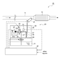
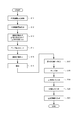
- FIG. 1 is an overall view showing a configuration example of an exhaust purification device provided with a reducing agent supply device according to an embodiment of the present invention. It is a block diagram which shows the structural example of an electronic controller. It is a timing chart shown in order to demonstrate an example of the control method of the reducing agent supply apparatus which concerns on embodiment of this invention. It is a flowchart for demonstrating an example of the control method of the reducing agent supply apparatus which concerns on embodiment of this invention. It is a figure which shows the structural example of the reducing agent supply apparatus concerning another embodiment of this invention.
- FIG. 1 is a diagram for explaining an example of the overall configuration of an exhaust gas purification device 10 provided with a reducing agent supply device 20 according to a first embodiment of the present invention.
- Exhaust gas purification device 10 is a device for purifying NO X in the exhaust gas, is provided in the exhaust passage 11 of an internal combustion engine such as a diesel engine (not shown).
- the exhaust purification device 10 includes a reduction catalyst 13 interposed in the middle of the exhaust passage 11 and a reducing agent supply device 20 for supplying a liquid reducing agent into the exhaust passage 11 upstream of the reduction catalyst 13. ing.
- the reduction catalyst 13 is a catalyst having a function of promoting the reduction of NO x in the exhaust, adsorbs ammonia generated from the liquid reducing agent, and selectively reduces NO x in the exhaust flowing into the catalyst with ammonia.
- the reducing agent supply device 20 of the present embodiment uses an aqueous urea solution as a liquid reducing agent, and ammonia is generated by the thermal decomposition or hydrolysis of the aqueous urea solution in the exhaust passage 11. Yes.
- a reducing agent supply device 20 includes a storage tank 21 in which a liquid reducing agent is accommodated, a pump unit 30 that pumps the liquid reducing agent, and an exhaust passage for the liquid reducing agent. 11 and a reducing agent injection valve 25 that injects the fuel into the inside.
- the pump unit 30 includes a pump 23 and a flow path switching valve 33. The reducing agent injection valve 25, the pump 23, and the flow path switching valve 33 are controlled by the ECU 40.
- the pump 23 and the storage tank 21 are connected by a first reducing agent passage 27, and the pump 23 and the reducing agent injection valve 25 are connected by a second reducing agent passage 28.
- a pressure sensor 31 is provided in the second reducing agent passage 28, as pressure detecting means for detecting the pressure in the second reducing agent passage 28, that is, the pressure of the liquid reducing agent pumped to the reducing agent injection valve 25, A pressure sensor 31 is provided.
- the pump 23 is connected to the first reducing agent passage 27 and the second reducing agent passage 28 via a flow path switching valve 33.
- the end of the first reducing agent passage 27 on the side of the storage tank 21 is located in the vicinity of the bottom surface of the storage tank 21 so that the liquid reducing agent can be sucked up.
- the flow path switching valve 33 is configured so that the liquid reducing agent pumped by the pump 23 flows in the positive direction from the storage tank 21 side to the reducing agent injection valve 25 side and from the reducing agent injection valve 25 side to the storage tank 21 side. It has a function of switching to the opposite direction of flow.
- the flow path switching valve 33 communicates the first reducing agent passage 27 with the inlet side 23a of the pump 23 in a non-energized state and the second reducing agent passage 28. While communicating with the outlet side 23b of the pump 23, the first reducing agent passage 27 is communicated with the outlet side 23b of the pump 23 and the second reducing agent passage 28 is communicated with the inlet side 23a of the pump 23 while being energized. It is configured.
- the flow path switching valve 33 is not energized in order to supply the liquid reducing agent to the reducing agent injection valve 25 side.
- the flow path switching valve 33 is energized in order to suck the liquid reducing agent in the reducing agent supply device 20 back into the storage tank 21.
- the configuration that allows the liquid reducing agent to be sucked back into the storage tank 21 when the internal combustion engine is stopped is not limited to the example in which the flow path switching valve 33 is provided.
- the liquid reducing agent can be configured to be sucked back by using a pump capable of reverse rotation.
- a return passage 29 having the other end connected to the storage tank 21 is branched in the middle of the second reducing agent passage 28.
- An end of the return passage 29 on the storage tank 21 side is connected to a gas phase portion in the storage tank 21.
- the storage tank 21 is provided with an air blizzard or the like, and is configured so that the internal pressure is maintained at atmospheric pressure.
- a throttle portion 37 having a reduced flow path area is provided in the middle of the return passage 29, so that the pressure in the second reducing agent passage 28 can be increased.
- the return passage 29 closer to the storage tank 21 than the throttling portion 37 is provided with a one-way valve 35 for preventing the liquid reducing agent from flowing from the storage tank 21 side to the second reducing agent passage 28 side. ing.
- the one-way valve 35 may be omitted.
- the pressure sensor 31 is provided in the pump unit 30, but may be provided at any position in the second reducing agent passage 28.
- the pump 23 pumps a liquid reducing agent at a predetermined flow rate by energization control by the ECU 40.
- an electromagnetic drive pump is used as the pump 23, and the output (discharge flow rate) of the pump 23 increases as the drive duty ratio increases.
- the pressure value (hereinafter referred to as “detected pressure”) Pu in the second reducing agent passage 28 detected by the pressure sensor 31 is a predetermined value set in advance.
- the output of the pump 23 is feedback-controlled so that the target pressure Pu_tgt is maintained.
- the ECU 40 detects the pressure sensor provided in the second reducing agent passage 28 while circulating the liquid reducing agent fed to the second reducing agent passage 28 to the storage tank 21 through the return passage 29.
- the output of the pump 23 is PID-controlled based on the difference ⁇ Pu between the detected pressure Pu detected by 31 and a predetermined target pressure Pu_tgt set in advance.
- the output of the pump 23 is fixed to a preset constant state.
- the output of the pump 23 may be controlled while observing the negative pressure state in the second reducing agent passage 28 even during the liquid reductant sucking back control.
- the reducing agent injection valve 25 is controlled to open and close by energization control, and injects a predetermined amount of liquid reducing agent into the exhaust passage 11.
- the reducing agent injection valve 25 is an electromagnetic on / off valve that closes in a non-energized state and opens in an energized state.
- the ECU 40 obtains the target injection amount Qdv_tgt based on a predetermined arithmetic expression, and assumes that the detected pressure Pu in the second reducing agent passage 28 is the target pressure Pu_tgt, for each predetermined injection cycle.
- the drive duty ratio corresponding to the target injection amount Qdv_tgt is determined, and energization control of the reducing agent injection valve 25 is performed.
- the drive duty ratio of the reducing agent injection valve 25 means the ratio of the valve opening time during one injection cycle.
- a three-way switching valve 39 is provided in the first reducing agent passage 27 that connects the pump 23 and the storage tank 21.
- the three-way switching valve 39 can be switched between a first state in which the passage on the pump 23 side communicates with the storage tank 21 side and a second state in which the passage on the pump 23 side is opened to the atmosphere.
- the three-way switching valve 39 is energized and controlled by the ECU 40, and is in a first state when energized and in a second state when energization is stopped.
- the three-way switching valve 39 provided in the reducing agent supply device 20 is a passage on the storage tank 21 side. Is to be blocked.
- FIG. 2 shows a configuration example in which functional blocks are used to represent portions related to the liquid reductant suck back control in the ECU 40 of the present embodiment.
- the ECU 40 is configured around a known microcomputer, and includes a collection control instruction unit 41, a flow path switching valve control unit 43, a pump drive control unit 45, a reducing agent injection valve drive control unit 47, and the like.
- the three-way switching valve drive control unit 49 is configured. Specifically, each of these units is realized by executing a program by a microcomputer.
- the ECU 40 includes a memory element (not shown) such as a RAM (Random Access Memory) and a ROM (Read Only Memory), a timer counter, a pump 23, a flow path switching valve 33, a reducing agent injection valve 25, a three-way switching valve 39, and the like.
- a drive circuit or the like for energizing is provided.
- the ECU 40 receives an ON / OFF signal of a key switch of the internal combustion engine and a sensor value of the pressure sensor 31, and stores values such as the detected pressure Pu in a storage element.
- the recovery control instruction unit 41 generates a liquid reducing agent recovery control start command Sp1 triggered by, for example, the key switch of the internal combustion engine being turned off.
- the collection control instruction unit 41 generates a collection control end command Sp2 when a predetermined time has elapsed.
- the flow path switching valve control unit 43 keeps the flow path switching valve 33 energized during a period from when the recovery control start command Sp1 is generated to when the recovery control end command Sp2 is generated when the internal combustion engine is stopped.
- a control signal for maintaining the liquid reducing agent to flow in the reverse direction is output to the drive circuit of the flow path switching valve.
- the pump drive control unit 45 drives the pump 23 with a predetermined constant output during a period from when the recovery control start command Sp1 is generated until the recovery control end command Sp2 is generated. As a result, a control signal is output to the pump drive circuit.
- the reducing agent injection valve drive control unit 47 opens the reducing agent injection valve 25 during a period from when the recovery control start command Sp1 is generated to when the recovery control end command Sp2 is generated when the internal combustion engine is stopped. Is output to the drive circuit of the reducing agent injection valve.
- the reducing agent injection valve drive control unit 47 opens the reducing agent injection valve 25 with a slight delay after energizing the flow path switching valve 33 and starting driving the pump 23.
- the three-way switching valve drive control unit 49 energizes the three-way switching valve 39 during a period from when the recovery control start command Sp1 is generated to when the recovery control end command Sp2 is generated when the internal combustion engine is stopped.
- the control signal for communicating the pump 23 and the storage tank 21 is output to the drive circuit of the three-way switching valve.
- the three-way switching valve drive control unit 49 stops energization to the three-way switching valve 39 at the end of the recovery control and opens the first reducing agent passage 27 on the pump 23 side to the atmosphere.
- FIG. 3 shows changes over time in the detected pressure Pu in the second reducing agent passage 28 when the clogging occurs in the reducing agent injection valve 25 and when no clogging occurs, the driving state of the flow path switching valve 33, and the reduction.
- the driving state of the agent injection valve 25, the driving state of the pump 23, and the driving state of the three-way switching valve 39 are shown.
- the solid line A indicates the transition of the detected pressure Pu when clogging does not occur
- the broken line B indicates when the clogging occurs.
- energization of the flow path switching valve 33 is started at time t1, so that the liquid reducing agent flows from the reducing agent injection valve 25 side to the storage tank 21 side. From this time t1, the detected pressure Pu in the second reducing agent passage 28 starts to decrease.
- the reducing agent injection valve 25 is opened.
- the detected pressure Pu in the second reducing agent passage 28 is lower than the atmospheric pressure Pair and is in a negative pressure state.
- the reason why there is a time interval between the start of energization of the flow path switching valve 33 and the opening of the reducing agent injection valve 25 is that the reducing agent injection valve 25 is moved in a state where the pressure in the second reducing agent passage 28 is positive. This is because the liquid reducing agent leaks into the exhaust passage 11 when the valve is opened.
- exhaust (air) is introduced into the reducing agent supply path through the injection hole of the reducing agent injection valve 25, and the liquid reducing agent is efficiently sucked back into the storage tank 21. Will be able to.
- step S ⁇ b> 13 the ECU 40 sets the flow path switching valve 33 to the energized stop state, sets the reducing agent injection valve 25 to the closed state, and sets the three-way switching valve 39 to the energized state.
- step S15 the ECU 40 starts energizing the flow path switching valve 33 and switches the flow path so that the liquid reducing agent flows from the reducing agent injection valve 25 side to the storage tank 21 side. Thereby, sucking back of the liquid reducing agent by the pump 23 is started. While the suction back control is being executed, the detected pressure Pu in the second reducing agent passage 28 is maintained in a negative pressure state.
- step S16 the ECU 40 energizes the reducing agent injection valve 25 and opens it.
- the reason why the opening of the reducing agent injection valve 25 is delayed is that the liquid reducing agent may leak into the exhaust passage 11 when the second reducing agent passage 28 is opened with a positive pressure.
- delaying the valve opening timing is not an essential matter in the present invention.
- step S17 the ECU 40 generates a recovery control end command Sp2 when a predetermined time has elapsed since the start of sucking back the liquid reducing agent, and accordingly, in step S18, the pump 23 is driven. Stop. Further, the ECU 40 stops energization to the three-way switching valve 39 in step S19. As a result, even if the first reducing agent passage 27 on the pump 23 side is opened to the atmosphere and the inside of the second reducing agent passage 28 is in an excessively negative pressure state, the liquid reducing agent in the storage tank 21 is pumped. The 23 side is not refilled.
- the ECU 40 stops energization of the flow path switching valve 33 in step S20, stops energization of the reducing agent injection valve 25 in step S21, and ends the liquid reductant suction back control.
- the reducing agent supply device 20 and the control method of the reducing agent supply device 20 perform the suck back when the liquid reductant suck back control is executed when the internal combustion engine is stopped.
- the first reducing agent passage 27 that connects the pump 23 and the storage tank 21 is opened to the atmosphere. Therefore, for example, even when an excessive negative pressure is generated in the second reducing agent passage 28 due to clogging of the reducing agent injection valve 25 or the like, the liquid reducing agent in the storage tank 21 is moved to the pump 23 side. Refilling can be prevented.
- the pump 23 is stopped, and then the energization to the three-way switching valve 39 is stopped, and the pump The first reducing agent passage 27 on the 23rd side is opened to the atmosphere. Therefore, it is possible to reliably prevent the liquid reducing agent from flowing to the open side of the atmosphere, and to reduce the possibility that the valve on the open side of the atmosphere will stick due to freezing and solidification of the liquid reducing agent.
- the reducing agent supply device 20 and the control method of the reducing agent supply device 20 according to the present embodiment are merely examples of one aspect of the present invention, and the above-described embodiments are within the scope of the present invention. Can be changed in
- the three-way switching valve 39 is provided in the first reducing agent passage 27 in the storage tank 21.
- the three-way switching valve 39 may make it provide in the 1st reducing agent channel
- the capacity of the first reducing agent passage 27 between the three-way switching valve 39 and the pump 23 can be reduced, and the refill amount on the pump 23 side can be reduced. Can be less.
Landscapes
- Engineering & Computer Science (AREA)
- Chemical & Material Sciences (AREA)
- Chemical Kinetics & Catalysis (AREA)
- Health & Medical Sciences (AREA)
- Combustion & Propulsion (AREA)
- Mechanical Engineering (AREA)
- General Engineering & Computer Science (AREA)
- Toxicology (AREA)
- Environmental & Geological Engineering (AREA)
- Biomedical Technology (AREA)
- Analytical Chemistry (AREA)
- General Chemical & Material Sciences (AREA)
- Oil, Petroleum & Natural Gas (AREA)
- Exhaust Gas After Treatment (AREA)
- Exhaust Gas Treatment By Means Of Catalyst (AREA)
- Control Of Vehicle Engines Or Engines For Specific Uses (AREA)
Priority Applications (4)
| Application Number | Priority Date | Filing Date | Title |
|---|---|---|---|
| US14/653,640 US9482134B2 (en) | 2012-12-26 | 2013-12-19 | Control method for reducing agent supply apparatus and reducing agent supply apparatus |
| EP13868567.2A EP2940264B1 (de) | 2012-12-26 | 2013-12-19 | Verfahren zur steuerung einer redundanten versorgungsvorrichtung und redundante versorgungsvorrichtung |
| CN201380068186.8A CN104870766B (zh) | 2012-12-26 | 2013-12-19 | 还原剂供给装置的控制方法及还原剂供给装置 |
| JP2014554375A JP6012086B2 (ja) | 2012-12-26 | 2013-12-19 | 還元剤供給装置の制御方法及び還元剤供給装置 |
Applications Claiming Priority (2)
| Application Number | Priority Date | Filing Date | Title |
|---|---|---|---|
| JP2012-282777 | 2012-12-26 | ||
| JP2012282777 | 2012-12-26 |
Publications (1)
| Publication Number | Publication Date |
|---|---|
| WO2014103869A1 true WO2014103869A1 (ja) | 2014-07-03 |
Family
ID=51020956
Family Applications (1)
| Application Number | Title | Priority Date | Filing Date |
|---|---|---|---|
| PCT/JP2013/084065 Ceased WO2014103869A1 (ja) | 2012-12-26 | 2013-12-19 | 還元剤供給装置の制御方法及び還元剤供給装置 |
Country Status (5)
| Country | Link |
|---|---|
| US (1) | US9482134B2 (de) |
| EP (1) | EP2940264B1 (de) |
| JP (1) | JP6012086B2 (de) |
| CN (1) | CN104870766B (de) |
| WO (1) | WO2014103869A1 (de) |
Families Citing this family (3)
| Publication number | Priority date | Publication date | Assignee | Title |
|---|---|---|---|---|
| DE102013105710B4 (de) * | 2013-06-04 | 2025-05-28 | Schaeffler Technologies AG & Co. KG | Verfahren zum Betrieb einer Vorrichtung zur Förderung einer Flüssigkeit |
| JP6445476B2 (ja) | 2016-01-29 | 2018-12-26 | 日立建機株式会社 | 建設機械 |
| US11873751B2 (en) * | 2020-11-13 | 2024-01-16 | Caterpillar Inc. | System and method for monitoring location of diesel exhaust fluid in a dosing system |
Citations (5)
| Publication number | Priority date | Publication date | Assignee | Title |
|---|---|---|---|---|
| JP2008151094A (ja) * | 2006-12-20 | 2008-07-03 | Aisan Ind Co Ltd | 内燃機関の排気浄化装置 |
| JP2010007617A (ja) | 2008-06-30 | 2010-01-14 | Denso Corp | 還元剤供給システム |
| JP2010024896A (ja) * | 2008-07-16 | 2010-02-04 | Denso Corp | 還元剤供給システム |
| JP2010084694A (ja) * | 2008-10-01 | 2010-04-15 | Denso Corp | 尿素水添加装置 |
| JP2011001895A (ja) * | 2009-06-19 | 2011-01-06 | Bosch Corp | 排気浄化装置及びその制御方法 |
Family Cites Families (14)
| Publication number | Priority date | Publication date | Assignee | Title |
|---|---|---|---|---|
| JP2005248823A (ja) | 2004-03-04 | 2005-09-15 | Hino Motors Ltd | 還元剤供給装置 |
| US7770384B2 (en) * | 2006-09-18 | 2010-08-10 | Ford Global Technologies, Llc | Ammonia vapor storage and purge system and method |
| DE102006061732A1 (de) * | 2006-12-28 | 2008-07-03 | Robert Bosch Gmbh | Vorrichtung zum Dosieren eines flüssigen Reduktionsmittels |
| JP2009002260A (ja) | 2007-06-22 | 2009-01-08 | Toyota Motor Corp | 排気ガス浄化装置 |
| DE102007044403B4 (de) * | 2007-09-18 | 2011-04-28 | Continental Automotive Gmbh | Vorrichtung zum Einbringen einer Reduktionsmittelflüssigkeit in ein Abgas einer Verbrennungsanlage |
| FR2921911A1 (fr) * | 2007-09-21 | 2009-04-10 | Inergy Automotive Systems Res | Systeme de stockage et d'injection d'une solution d'additif dans des gaz d'echappement d'un moteur. |
| DE102008009650A1 (de) * | 2008-02-18 | 2009-08-27 | Robert Bosch Gmbh | Störungssicheres System zur Schadstoffverminderung |
| DE602008003407D1 (de) * | 2008-05-09 | 2010-12-23 | Magneti Marelli Spa | Einspritzverfahren und Vorrichtung zum Einspritzen eines Reduktionsmittels in ein Abgassystem in einem Verbrennungsmotor |
| EP2151559B1 (de) | 2008-08-08 | 2011-04-06 | Magneti Marelli S.p.A. | Einspritzvorrichtung zum Einspritzen einer Verringerungssubstanz in ein Abgassystem in einem Verbrennungsmotor |
| DE102009000097A1 (de) * | 2009-01-09 | 2010-07-15 | Robert Bosch Gmbh | Fördereinrichtung für ein SCR-System |
| JP4911193B2 (ja) * | 2009-04-28 | 2012-04-04 | 株式会社デンソー | 内燃機関の排気浄化システム |
| JP5325850B2 (ja) * | 2009-10-30 | 2013-10-23 | ボッシュ株式会社 | 還元剤噴射弁の異常検出装置及び異常検出方法、並びに内燃機関の排気浄化装置 |
| US20120020857A1 (en) * | 2010-07-21 | 2012-01-26 | Isada Raymond Upano | Dosing system having recirculation heating and vacuum draining |
| US20130000743A1 (en) * | 2011-06-29 | 2013-01-03 | Ti Group Automotive Systems, L.L.C. | Scr fluid distribution and circulation system |
-
2013
- 2013-12-19 EP EP13868567.2A patent/EP2940264B1/de not_active Not-in-force
- 2013-12-19 WO PCT/JP2013/084065 patent/WO2014103869A1/ja not_active Ceased
- 2013-12-19 JP JP2014554375A patent/JP6012086B2/ja active Active
- 2013-12-19 US US14/653,640 patent/US9482134B2/en not_active Expired - Fee Related
- 2013-12-19 CN CN201380068186.8A patent/CN104870766B/zh not_active Expired - Fee Related
Patent Citations (5)
| Publication number | Priority date | Publication date | Assignee | Title |
|---|---|---|---|---|
| JP2008151094A (ja) * | 2006-12-20 | 2008-07-03 | Aisan Ind Co Ltd | 内燃機関の排気浄化装置 |
| JP2010007617A (ja) | 2008-06-30 | 2010-01-14 | Denso Corp | 還元剤供給システム |
| JP2010024896A (ja) * | 2008-07-16 | 2010-02-04 | Denso Corp | 還元剤供給システム |
| JP2010084694A (ja) * | 2008-10-01 | 2010-04-15 | Denso Corp | 尿素水添加装置 |
| JP2011001895A (ja) * | 2009-06-19 | 2011-01-06 | Bosch Corp | 排気浄化装置及びその制御方法 |
Also Published As
| Publication number | Publication date |
|---|---|
| EP2940264A1 (de) | 2015-11-04 |
| JPWO2014103869A1 (ja) | 2017-01-12 |
| US9482134B2 (en) | 2016-11-01 |
| JP6012086B2 (ja) | 2016-10-25 |
| EP2940264B1 (de) | 2017-08-02 |
| US20150308317A1 (en) | 2015-10-29 |
| CN104870766A (zh) | 2015-08-26 |
| EP2940264A4 (de) | 2016-01-13 |
| CN104870766B (zh) | 2017-11-14 |
Similar Documents
| Publication | Publication Date | Title |
|---|---|---|
| JP5139765B2 (ja) | 還元剤供給システムの制御装置及び制御方法 | |
| US8590291B2 (en) | Control device of reducing agent supply apparatus, reducing agent collection method, and exhaust gas purification apparatus | |
| JP6088865B2 (ja) | 還元剤供給装置の制御方法 | |
| WO2014061377A1 (ja) | 還元剤回収制御方法及び還元剤供給装置並びに電子制御装置 | |
| JP6016127B2 (ja) | 内燃機関の排気浄化装置 | |
| WO2011145573A1 (ja) | Scrシステム | |
| US9816416B2 (en) | Control apparatus and control method for reducing agent supply apparatus | |
| JP6017866B2 (ja) | 還元剤供給装置及び液体還元剤の回収制御方法並びに排気浄化装置 | |
| US10844768B2 (en) | Abnormality determination device | |
| JP2012127214A (ja) | 還元剤供給装置及び内燃機関の排気浄化装置 | |
| JP6012086B2 (ja) | 還元剤供給装置の制御方法及び還元剤供給装置 | |
| JP6693408B2 (ja) | 尿素水撹拌制御装置 | |
| JP6172468B2 (ja) | 内燃機関の排気浄化装置 | |
| JP2012163029A (ja) | 還元剤供給装置 | |
| JP5914151B2 (ja) | 還元剤噴射弁の異常検出装置及び還元剤供給装置 | |
| JP2016128678A (ja) | 尿素噴射装置 | |
| JP2014015856A (ja) | 還元剤供給装置及び液体還元剤の回収制御方法並びに排気浄化装置 | |
| JP2012127308A (ja) | 還元剤供給装置及び内燃機関の排気浄化装置 | |
| JP7013820B2 (ja) | 還元剤添加システム | |
| JP2017110515A (ja) | 還元剤供給装置 | |
| JP7783691B2 (ja) | 制御装置 | |
| JP2024103956A (ja) | 還元剤供給システム及び還元剤供給システムの制御装置並びに還元剤供給システムの制御方法 | |
| JP6183297B2 (ja) | 内燃機関の排気浄化装置 |
Legal Events
| Date | Code | Title | Description |
|---|---|---|---|
| 121 | Ep: the epo has been informed by wipo that ep was designated in this application |
Ref document number: 13868567 Country of ref document: EP Kind code of ref document: A1 |
|
| ENP | Entry into the national phase |
Ref document number: 2014554375 Country of ref document: JP Kind code of ref document: A |
|
| REEP | Request for entry into the european phase |
Ref document number: 2013868567 Country of ref document: EP |
|
| WWE | Wipo information: entry into national phase |
Ref document number: 2013868567 Country of ref document: EP |
|
| WWE | Wipo information: entry into national phase |
Ref document number: 14653640 Country of ref document: US |
|
| NENP | Non-entry into the national phase |
Ref country code: DE |