WO2014103884A1 - 制振合金 - Google Patents
制振合金 Download PDFInfo
- Publication number
- WO2014103884A1 WO2014103884A1 PCT/JP2013/084119 JP2013084119W WO2014103884A1 WO 2014103884 A1 WO2014103884 A1 WO 2014103884A1 JP 2013084119 W JP2013084119 W JP 2013084119W WO 2014103884 A1 WO2014103884 A1 WO 2014103884A1
- Authority
- WO
- WIPO (PCT)
- Prior art keywords
- mass
- deformation
- alloy
- damping alloy
- less
- Prior art date
- Legal status (The legal status is an assumption and is not a legal conclusion. Google has not performed a legal analysis and makes no representation as to the accuracy of the status listed.)
- Ceased
Links
Images

Classifications
-
- C—CHEMISTRY; METALLURGY
- C22—METALLURGY; FERROUS OR NON-FERROUS ALLOYS; TREATMENT OF ALLOYS OR NON-FERROUS METALS
- C22C—ALLOYS
- C22C38/00—Ferrous alloys, e.g. steel alloys
-
- C—CHEMISTRY; METALLURGY
- C21—METALLURGY OF IRON
- C21D—MODIFYING THE PHYSICAL STRUCTURE OF FERROUS METALS; GENERAL DEVICES FOR HEAT TREATMENT OF FERROUS OR NON-FERROUS METALS OR ALLOYS; MAKING METAL MALLEABLE, e.g. BY DECARBURISATION OR TEMPERING
- C21D6/00—Heat treatment of ferrous alloys
- C21D6/004—Heat treatment of ferrous alloys containing Cr and Ni
-
- C—CHEMISTRY; METALLURGY
- C21—METALLURGY OF IRON
- C21D—MODIFYING THE PHYSICAL STRUCTURE OF FERROUS METALS; GENERAL DEVICES FOR HEAT TREATMENT OF FERROUS OR NON-FERROUS METALS OR ALLOYS; MAKING METAL MALLEABLE, e.g. BY DECARBURISATION OR TEMPERING
- C21D6/00—Heat treatment of ferrous alloys
- C21D6/005—Heat treatment of ferrous alloys containing Mn
-
- C—CHEMISTRY; METALLURGY
- C22—METALLURGY; FERROUS OR NON-FERROUS ALLOYS; TREATMENT OF ALLOYS OR NON-FERROUS METALS
- C22C—ALLOYS
- C22C38/00—Ferrous alloys, e.g. steel alloys
- C22C38/06—Ferrous alloys, e.g. steel alloys containing aluminium
-
- C—CHEMISTRY; METALLURGY
- C22—METALLURGY; FERROUS OR NON-FERROUS ALLOYS; TREATMENT OF ALLOYS OR NON-FERROUS METALS
- C22C—ALLOYS
- C22C38/00—Ferrous alloys, e.g. steel alloys
- C22C38/18—Ferrous alloys, e.g. steel alloys containing chromium
- C22C38/34—Ferrous alloys, e.g. steel alloys containing chromium with more than 1.5% by weight of silicon
-
- C—CHEMISTRY; METALLURGY
- C22—METALLURGY; FERROUS OR NON-FERROUS ALLOYS; TREATMENT OF ALLOYS OR NON-FERROUS METALS
- C22C—ALLOYS
- C22C38/00—Ferrous alloys, e.g. steel alloys
- C22C38/18—Ferrous alloys, e.g. steel alloys containing chromium
- C22C38/40—Ferrous alloys, e.g. steel alloys containing chromium with nickel
- C22C38/58—Ferrous alloys, e.g. steel alloys containing chromium with nickel with more than 1.5% by weight of manganese
-
- C—CHEMISTRY; METALLURGY
- C21—METALLURGY OF IRON
- C21D—MODIFYING THE PHYSICAL STRUCTURE OF FERROUS METALS; GENERAL DEVICES FOR HEAT TREATMENT OF FERROUS OR NON-FERROUS METALS OR ALLOYS; MAKING METAL MALLEABLE, e.g. BY DECARBURISATION OR TEMPERING
- C21D2211/00—Microstructure comprising significant phases
- C21D2211/001—Austenite
-
- C—CHEMISTRY; METALLURGY
- C21—METALLURGY OF IRON
- C21D—MODIFYING THE PHYSICAL STRUCTURE OF FERROUS METALS; GENERAL DEVICES FOR HEAT TREATMENT OF FERROUS OR NON-FERROUS METALS OR ALLOYS; MAKING METAL MALLEABLE, e.g. BY DECARBURISATION OR TEMPERING
- C21D2211/00—Microstructure comprising significant phases
- C21D2211/008—Martensite
-
- C—CHEMISTRY; METALLURGY
- C21—METALLURGY OF IRON
- C21D—MODIFYING THE PHYSICAL STRUCTURE OF FERROUS METALS; GENERAL DEVICES FOR HEAT TREATMENT OF FERROUS OR NON-FERROUS METALS OR ALLOYS; MAKING METAL MALLEABLE, e.g. BY DECARBURISATION OR TEMPERING
- C21D8/00—Modifying the physical properties of ferrous metals or ferrous alloys by deformation combined with, or followed by, heat treatment
Definitions
- the present invention relates to a vibration damping alloy capable of elastic-plastic deformation with low stress and having excellent fatigue characteristics.
- the damping damper is a damping device that absorbs the vibration energy input to the building due to wind or earthquake and prevents the vibration from reaching the structure body.
- the vibration dampers that have been proposed and developed so far can be broadly classified into viscous dampers (Patent Document 1), viscoelastic dampers (Patent Document 2), lead dampers (Patent Document 3), and elastic-plastic dampers (Patent Document 4). and so on.
- elasto-plastic dampers using low-yield point steel are particularly popular in recent years because they are superior in performance, cost, and maintainability as damping dampers that reduce the shaking of structures, especially during earthquakes. It is out.
- This elasto-plastic damper has a function of reducing vibration of the building by absorbing seismic energy input to the building mainly as thermal energy by plastic deformation of an alloy used as a core material for the damper.
- the plastic deformation characteristics of the damping alloy as the core material have an important effect on the performance of the damping damper. It is desirable that the yield stress or yield strength of the damping alloy is low in order to cause plastic deformation characteristics earlier than the structure body. In addition, after the earthquake occurs, the damper core itself is repeatedly elasto-plastically deformed. From the viewpoint of long-term use, changes in mechanical properties and metal fatigue due to repeated hardening are problems.
- the most widely used damping alloy is a low yield point steel whose yield stress or 0.2% proof stress is intentionally reduced to about 100 to 225 MPa.
- the lower the yield stress the more elastoplastic deformation occurs.
- the initial repeated hardening rate is high, and the fatigue life is naturally superior to the steel used for the main frame such as columns and beams of the structure, but there is no significant difference in fatigue characteristics and there is a clear advantage. Is hard to say.
- a mechanism for heating the damper member is required, but according to the above proposal, at least without providing such a heating mechanism, the curing rate due to repeated deformation is low, Because of its long fatigue life, it can be used as a high-performance damping alloy that works effectively against long-period ground motion.
- Patent Document 5 Although it is suggested in Patent Document 5 that the Fe—Mn—Si-based shape memory alloy is effective as a vibration damping alloy with almost the same composition, the progress as a result of subsequent research suggests that it is suitable as a shape memory alloy. It has also become clear that the component range and the proper component range as a damping alloy are not completely consistent.
- an alloy to which NbC is added to improve shape memory characteristics has an extremely high stress amplitude of 650 MPa or more with respect to repeated tensile compression deformation having an amplitude of 1%. If the core material for the elastoplastic damper is not elastoplastically deformed prior to the structure main body, the vibration absorbing effect for protecting the structure main body cannot be exhibited.
- the strength must be lower than the structure body such as a building. Therefore, when a material having high material strength is used for the core material for the damper, it is necessary to reduce the cross-sectional area of the damper so as not to exceed the strength of the structure.
- a damper with a small cross-sectional area has a high risk of buckling during compression deformation. Therefore, in order to secure a wide applicable range as a damper, it is advantageous that the core material for the damper has a certain low material strength. .
- the inventors further studied and tried to control the plastic deformation characteristics by adding Al based on a Fe-30Mn-6Si shape memory alloy containing no precipitate such as NbC.
- an alloy containing 1 to 3% by mass of Al is useful as a damping alloy capable of operating at a stress amplitude as low as about 300 MPa with respect to repeated tensile compression deformation having an amplitude of 1% (for example, , See Patent Document 6).
- Non-Patent Document 2 the addition of more than 1% by mass of Al to the Fe-30Mn-6Si shape memory alloy almost eliminates the shape memory effect. It is clear that the optimum component range of the damping alloy does not always match.
- the core material for elasto-plastic dampers can be produced at low cost using existing mass-production steel production equipment, which is an important requirement for promoting earthquake resistance of structures at an early stage. Since the known damping alloy disclosed in Patent Document 6 contains Mn at a high concentration of 30% by mass, it is difficult to make it with equipment for producing general steel materials such as arc furnace melting.
- Non-Patent Document 4 second phases such as ⁇ ferrite phase, silicide, ⁇ ′ martensite phase and the like are easily formed in the Fe—Mn—Si based alloy to which Cr or Ni is added. The effect of aging on fatigue properties is also unclear.
- the fatigue characteristics of Fe-Mn-Cr-Ni alloys are also examined from the same viewpoint, and the relationship between fatigue characteristics and structure is partially publicized (for example, see Non-Patent Document 6).
- the plastic deformation structure of these Fe-Mn alloys and Fe-Mn-Cr-Ni alloys is a complex combination of deformation twins, ⁇ 'martensite phase, ⁇ martensite phase, stacking faults, dislocations, etc. Yes, it cannot be said that the relationship between fatigue properties and structure has been fully elucidated.
- ⁇ -martensite is effective in improving fatigue properties.
- TWIP steel and Fe—Mn—Cr—Ni alloys ⁇ -martensite Little is known about the impact of sites on fatigue properties.
- austenitic structural steels such as TWIP steel are usually designed as components so that the yield strength is as high as possible as structural materials, and are not suitable as core materials for elastic-plastic dampers.
- an Fe—Mn—Cr—Si—Al—C alloy is disclosed as a damping alloy utilizing the ⁇ martensite phase (see, for example, Patent Document 7).
- this damping alloy improves the internal friction in the elastic deformation region by containing 15% or more of the ⁇ martensite phase in the ⁇ austenite phase in the state before deformation, and the fatigue characteristics against elastoplastic deformation are disclosed. It has not been.
- properties required for damping steel or damping alloy used mainly for the purpose of protecting the structure from earthquakes are: Low fatigue strength, low cure rate, large strain and long fatigue life (large number of repeated fractures).
- damping alloy as a core material for an elastoplastic damper having all these properties in a well-balanced manner.
- JP-A-5-263858 Japanese Patent Laid-Open No. 2001-146855 JP-A-5-106367 Japanese Patent Laid-Open No. 5-26274 JP 2006-194287 A JP 2008-56987 A JP 2011-214127 A
- the present invention eliminates the conventional problems from the background as described above, reduces the proof stress and the stress amplitude after repeated tensile and compressive deformation in Fe—Mn— (Cr, Ni) —Si based alloys, and repeats fracture.
- An object is to provide a damping alloy for an elasto-plastic damper that can be used without maintenance even after long-period ground motion and can be mass-produced.
- the damping alloy of the present invention is characterized by the following.
- the damping alloy according to the first aspect of the invention is characterized by containing 10% by mass ⁇ Mn ⁇ 20% by mass, 2% by mass ⁇ Ni ⁇ 10% by mass.
- the vibration-damping alloy of the first or second invention contains 2% by mass ⁇ Si ⁇ 6% by mass.
- the metal structure of the alloy after the plastic working and the solution heat treatment is less than 15% by volume of an ⁇ martensite phase (HCP structure).
- HCP structure ⁇ martensite phase
- the balance consists only of ⁇ -austenite phase (FCC structure), and after this state, after repeating tensile and compressive deformation with an amplitude of 1% for 100 cycles or more, an ⁇ -martensite phase of less than 50 volume%, 3 volumes % ⁇ 'martensite phase and the balance is ⁇ austenite phase.
- the stress amplitude is 400 MPa or less after a tensile strength deformation of 280 MPa or less and an amplitude of 1% is repeated for 100 cycles or more, and the fracture.
- the number of repetitions is 2000 cycles or more.
- the damping alloy of the present invention has an added amount of Mn of 28% by mass or less, it can be easily manufactured as compared with the conventional Fe-30Mn-Si-Al damping alloy.
- the amount of Mn added is less than 20% by mass, the conventional Fe-30Mn-Si-Al vibration-damping alloy could only be melted in a vacuum induction heating furnace, but could be melted in an arc furnace. Therefore, a significant cost reduction is expected.
- the number of repetitions of fracture is almost one digit longer and can be used for long-period ground motion.
- the damping alloy under the conditions defined in the present invention has a proof stress of 280 MPa or less, a stress amplitude after repeating tensile compression deformation of 1% amplitude 100 times or more, 400 MPa or less, and a number of repeated cycles of 2000 cycles or more, Compared to conventional NbC-containing Fe-Mn-Si shape memory / damping alloys, it has lower proof stress and stress amplitude, and can be operated at a low strength level. Can be applied to a wide range.
- a damping alloy refers to a structural material that absorbs mechanical vibrations in machine tools, precision equipment, automobiles, etc., mainly increasing internal friction in the elastic deformation region and achieving high strength as a metal material. .
- vibration suppression is also used in the present invention, but its main object is suppression of vibrations to structures during earthquakes.
- the suppression of relatively minute vibrations caused by wind fluctuations is included in the effect.
- the damping alloy of the present invention is a Fe—Mn— (Cr, Ni) —Si based alloy in which elastoplastic deformation is controlled by adjusting the contents of Mn, Cr, Ni, and Si so that ⁇ -austenite phase and ⁇ -martensite. Creates a situation that reversibly proceeds by phase interconversion and suppresses irreversible deformation such as the formation of ⁇ ′ martensite phase, and the stress amplitude after repeated tensile compression deformation with a yield strength of 280 MPa or less and an amplitude of 1%. It is a vibration-damping alloy having 400 MPa or less and a number of repeated fractures of 2000 cycles or more.
- the plastic deformation mechanism in an austenitic iron-based alloy is not only the lattice dislocation sliding motion, which is a general metal plastic deformation mechanism, but also the lattice dislocations decompose into two partial dislocations and a stacking fault sandwiched between them. It takes various forms such as sliding motion of moving dislocations, twin deformation, ⁇ martensitic transformation, ⁇ 'martensitic transformation, and usually multiple plastic deformation mechanisms are developed simultaneously.
- the structural change caused by the tensile and compressive plastic deformation is caused by repetitive hardening by creating a state in which the structural change proceeds reversibly by the bidirectional martensitic transformation of the ⁇ austenite phase and the ⁇ martensite phase. Increase the number of repeated fractures.
- the state before deformation is a ⁇ -austenite single phase
- the plastic deformation mechanism proceeds mainly by ⁇ -martensite transformation.
- ⁇ martensite transformation may contain some of the twin deformation, lattice dislocation slip, and extended dislocation slip that are inevitably simultaneously generated, but ⁇ 'martensite transformation significantly hardens the alloy. The occurrence must be suppressed.
- Mn An essential additive element that has a central influence on the plastic deformation mechanism of the Fe—Mn— (Cr, Ni) —Si alloy is Mn.
- Mn stabilizes the ⁇ austenite phase in the iron-based alloy and lowers the stacking fault energy to create a state in which martensitic transformation from the ⁇ austenite phase to the ⁇ martensite phase is likely to occur.
- austenite stabilizing action of Mn can be partially replaced by Ni, and the lowering effect of stacking fault energy can be partially replaced by Cr.
- Mn equivalent ([% Mn] eq) [% Mn] + [% Cr] +2 [% Ni] +5 [% Al] (1) [% Mn], [% Cr], [% Ni], and [% Al] in the formula mean mass% of Mn, Cr, Ni, and Al as chemical components of the damping alloy.
- the range of the Mn equivalent for expressing the bi-directional martensitic transformation between the ⁇ austenite phase and the ⁇ martensite phase is set to the condition expressed by the following formula (2). 37 ⁇ [% Mn] eq ⁇ 45 (2)
- the Mn equivalent is 37% by mass or less, the thermodynamic stability of the ⁇ -martensite phase becomes very high. Therefore, even if the ⁇ -martensite phase once induced to deform becomes a ⁇ -austenite phase even if deformed in the reverse direction thereafter. No reverse transformation.
- the volume fraction of the ⁇ -martensite phase monotonously increases due to repeated tensile and compressive deformation, and when the volume fraction reaches 50% by volume or more, the probability of crack occurrence and cracks at the locations where the formed ⁇ -martensite phases collide with each other.
- the extension speed increases and the number of repeated ruptures decreases.
- Si which is another essential additive element, hardly affects the Mn equivalent, but improves the reversibility of the bi-directional martensitic transformation between the ⁇ -austenite phase and the ⁇ -martensite phase and improves the number of repetitions of fracture. It was clarified by experiment. Even when Si is not added, the number of repetitions of breakage of about 2000 cycles can be achieved. However, the addition of Si greatly increases the number of repetitions of breakage, and is most effective in the vicinity of 4% by mass.
- the alloy when Si is added excessively, the number of repetitions of fracture is decreased, and particularly when 6.5% by mass or more is added, the alloy may be remarkably hardened, resulting in a problem that the stress amplitude of repeated tensile compression deformation increases. .
- the balance adjustment of the total amount of Si and Al is important. The higher the ferrite stabilizing element concentration and the lower the austenite stabilizing element concentration, the more easily the ⁇ ferrite phase is formed. When both the ferrite stabilizing element concentration and the austenite stabilizing element concentration are low, the ⁇ ′ martensite phase is easily formed. Become.
- Mn is an essential additive element that has two effects of stabilizing austenite and lowering stacking fault energy.
- the damping alloy of Patent Document 6 in which as much as 30% by mass of Mn is added, the Mn yield due to evaporation or oxidation of Mn. It is difficult to melt at a cost that can be put to practical use.
- the amount of Mn added is set to 28% by mass or less by adding Cr or Ni. Further, if the amount of Mn added is less than 20% by mass, an alloy can be produced by melting in an arc furnace suitable for mass production.
- the amount of Mn added is 5 mass% ⁇ Mn ⁇ 28 mass%, more preferably 10 mass% ⁇ Mn ⁇ 20 mass%.
- ⁇ Cr> Cr is an element that reduces the stacking fault energy of the ⁇ austenite phase and promotes the martensitic transformation to the ⁇ martensite phase to improve the fatigue characteristics of the vibration damping alloy of the present invention. Furthermore, it contributes to improving corrosion resistance and high-temperature oxidation resistance.
- the amount of Cr added is in the range of 0 mass% ⁇ Cr ⁇ 15 mass%.
- Ni is an element that substitutes for the austenite stabilizing action of Mn.
- the addition amount of Mn is less than 20% by mass, a ⁇ -austenite single phase cannot be obtained as a state before deformation unless Ni as an austenite stabilizing element is added by 2% by mass or more.
- Ni which is an expensive element, is preferably less than 10% by mass.
- the amount of Ni added is in the range of 0 mass% ⁇ Ni ⁇ 15 mass%, more preferably 2 mass% ⁇ Ni ⁇ 10 mass%.
- ⁇ Si> Si is an essential element of the Fe—Mn—Si-based shape memory alloy, and its component range is 3.5 to 8 mass%, but the industrially available Si concentration range is 5 to 6 mass%. It is as follows.
- the amount of Si to be added is 0 mass% ⁇ Si ⁇ 6.5 mass%, more preferably 2 mass% ⁇ Si in order to make the number of fracture repetitions 2000 cycles or more. ⁇ 6 mass%.
- Al is an element that affects the Mn equivalent by a factor of 5, it may be added as an alternative element for Mn.
- C and N have a function to solidify and harden the alloy, and increase the yield strength and impair the performance as a core material for an elastoplastic damper. %, N ⁇ 0.08% by mass.
- elements such as Nb, Ta, V, Ti, and Mo that have a high affinity with C and N are added to form carbides and nitrides. Forming objects is widely practiced in the field.
- Nb, Ta, V, Ti, and Mo may be added to remove solid solution C or solid solution N by applying a conventional method.
- Nb ⁇ 0.05 mass%
- Ta ⁇ 0.05 mass%
- V ⁇ 0.05 mass%
- Ti ⁇ 0.05 mass%
- Mo ⁇ 0.05 mass%
- the state before deformation is preferably a ⁇ austenite single phase, but may contain an ⁇ martensite phase as long as the amount is small.
- An alloy adjusted to a state in which ⁇ martensite transformation is likely to be induced by deformation may cause an ⁇ martensite phase to be formed unintentionally due to environmental temperature changes or processing effects.
- the tensile and compressive plastic deformation of the damping alloy of the present invention is mainly performed by alternately generating martensitic transformation from ⁇ austenite phase to ⁇ martensite phase and its reverse transformation.
- the ⁇ -martensite phase induced during tensile deformation reversely transforms into a ⁇ -austenite phase when the deformation direction is reversed to compression.
- compressive deformation produces a new epsilon martensite phase with a crystal orientation different from that at the time of tensile deformation as well as reverse transformation of the tensile-induced epsilon martensite phase.
- This compression-induced ⁇ martensite phase also reversely transforms into a ⁇ austenite phase when the deformation is reversed again to tension.
- the tensile-induced ⁇ and the compression-induced ⁇ are alternately generated and disappeared by repeated tensile compression, so that the cumulative volume fraction increase of the ⁇ martensite phase due to repeated tensile compression deformation is small. This is the reason why the damping alloy is excellent in fatigue characteristics.
- the volume fraction of the ⁇ -martensite phase gradually increases, but when it exceeds 50% by volume, the probability of crack generation and crack extension rate increase, leading to fracture. There is. Therefore, in order to set the number of repetitions of breakage to 2000 cycles or more with respect to a tensile compression deformation with an amplitude of 1%, it is desirable that the volume ratio of ⁇ -martensite after 2000 cycles deformation is less than 50% by volume.
- the ⁇ ′ martensite phase hardens the alloy, its volume ratio should be less than 3% by volume.
- the stress amplitude increases due to hardening, and the increase in the stress amplitude induces further ⁇ ′ martensite phase transformation in a chain, and therefore, the stress level increases. Not only does this reduce the damper performance, but it also leads to a reduction in the number of repeated fractures.
- the yield strength of the damping alloy of the present invention is 280 MPa or less. If the yield strength is higher than this, the cross-sectional area of the damper core material for optimizing the operation start strength of the damper becomes too small, and it becomes easy to buckle at the time of elastic-plastic deformation. In order to avoid buckling, a buckling stiffening jig must be installed. However, the installation of the buckling stiffening jig increases the manufacturing cost of the damper member.
- the stress amplitude after repeating the tensile and compressive deformation with an amplitude of 1% 100 times or more is 400 MPa or less.
- the damping alloy of the present invention is intended to be used for damping devices such as high-rise buildings as a core material for damping dampers that can cope with long-period ground motions.
- the number of repetitions is 2000 cycles or more.
- Examples 1 to 6 are also indicated by symbols 2S, 4S, 6S, 2A, 25M8N, and 25M15C to facilitate understanding of the characteristics of the blending components of Examples and Comparative Examples, and Comparative Examples 1 to 8 Are also shown as symbols 0S, 8S, 5M, 25M, 2N, 15N, PRE, 30M1A.
- Low cycle fatigue test pieces with a parallel part diameter of 8 mm were prepared from each ingot of Examples 1 to 6 and Comparative Examples 1 to 8 by lathe processing, and 0.1 Hz triangular wave, 1% amplitude strain control in room temperature atmosphere. A low cycle fatigue test was conducted.
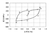
- FIG. 1 shows the relationship between stress and strain in the first cycle of tensile compression deformation of Example 2 (4S).
- the tensile plastic strain also decreases following the elastic deformation portion BC in which the tensile elastic stress decreases in proportion to the decrease in tensile strain, and the strain becomes zero at point D.
- compressive plastic strain occurs when compression deformation progresses.
- point E of -1% the deformation again turns from compression to tension, and then the elastic deformation EF and plastic deformation FG are followed, and the first cycle is completed.
- the second cycle starts along the curve GB ′ represented by a dotted line, and thereafter the same deformation as the first cycle is repeated.
- Curing rate (H) ( ⁇ a100 ⁇ a1) / ⁇ a1 (4)
- Table 2 shows the yield strength, the first cycle stress amplitude, the 100th cycle stress amplitude, the curing rate, and the final number of repetitions obtained from these results.
- Examples 1 to 6 (2S, 4S, 6S, 2A, 25M8N, 25M15C) all have a yield strength of 280 MPa or less, a stress amplitude of the 100th cycle of 400 MPa or less, and a final number of repetitions of 2000 cycles or more.
- the number of repetitions of fracture was slightly less than 2000.
- Comparative Example 2 8S in which Si was added in a larger amount than the component range of the present invention, a sample could not be prepared due to rolling cracks. The occurrence of cracking is thought to be due to the formation of a low melting intermetallic compound.
- Comparative Example 5 in which the amount of Ni added was reduced to 2% by mass as compared with the inventive material, and as a result, the Mn equivalent was reduced to 29, repetitive curing was remarkably high, and the number of repeated fractures was 1000 or less. This is considered to be due to the formation of 50 volume% or more of the ⁇ martensite phase and the ⁇ ′ martensite phase.
- Comparative Example 6 (15N) containing 15% by mass of Ni and higher in concentration than the Examples, cracks occurred during hot rolling, and a test piece could not be produced. This is considered to be because Ni formed a low melting point intermetallic compound with Si.
- Comparative Example 7 is an NbC precipitate addition type damping alloy disclosed in Patent Document 5.
- the number of repetitions of fracture is excellent at 3000 cycles or more, but the stress amplitude is extremely high at 620 MPa.
- Comparative Example 8 (30M1A) is an Al-added vibration damping alloy disclosed in Patent Document 6. Although the number of repeated fractures is 2000 or more and the stress amplitude is low, Mn is contained in an amount of 30% by mass, so that it is not suitable for mass production.
- the damping alloys of Examples 1 to 6 under the conditions specified in the present invention have lower proof stress and stress amplitude after repeated tensile and compressive deformation than the alloys of Comparative Examples 1 to 8 outside the conditions. It was confirmed that the damping alloy can be used without maintenance even after long-period ground motion and can be mass-produced.
- the damping alloy of the present invention is an elasto-plastic damper that suppresses the vibration of building structures due to earthquakes, wind fluctuations, etc., operates at low stress, and can be used maintenance-free even when repeatedly exposed to large earthquakes It becomes possible to manufacture a simple low-cost vibration damping device.
- a high-performance damper that does not impair the damping performance even if a long-amplitude vibration such as long-period ground motion continues for a long time, it can be used especially for damping high-rise buildings.
- building structures are places that are repeatedly deformed with large strains in all forms such as chemical plants, power plants, halls, towers, fuel tanks, elevated railways / roads, bridges, pipelines, tunnels, wind power generation facilities, etc. It is expected to be effective in suppressing vibrations.
Landscapes
- Chemical & Material Sciences (AREA)
- Engineering & Computer Science (AREA)
- Materials Engineering (AREA)
- Mechanical Engineering (AREA)
- Metallurgy (AREA)
- Organic Chemistry (AREA)
- Physics & Mathematics (AREA)
- Thermal Sciences (AREA)
- Crystallography & Structural Chemistry (AREA)
- Vibration Prevention Devices (AREA)
- Heat Treatment Of Steel (AREA)
- Buildings Adapted To Withstand Abnormal External Influences (AREA)
Abstract
少なくともCr、Niのいずれかを含有するFe-Mn-(Cr、Ni)-Si系の制振合金、又はさらにAlを含有する制振合金であって、成分組成として、5質量%≦Mn≦28質量%、0質量%≦Cr≦15質量%、0質量%≦Ni<15質量%、0質量%<Si<6.5質量%、0質量%≦Al<3質量%、残部Fe及び不可避不純物を含有し、[%Ni]+0.5[%Mn]>0.75[%Cr]+1.125[%Si]+2[%Al]、かつ、37<[%Mn]+[%Cr]+2[%Ni]+5[%Al]<45(式中[%Ni]、[%Mn]、[%Cr]、[%Si]、[%Al]は、Ni、Mn、Cr、Si、Alの質量%を意味する)の条件を満足することを特徴とする。これにより、Fe-Mn-(Cr、Ni)-Si系合金において、耐力と繰り返し引張圧縮変形後の応力振幅を低下させ、かつ破断繰り返し数を増加させて、長周期地震動後もメンテナンスフリーで使用可能で、かつ量産可能な弾塑性ダンパー用の制振合金を提供することができる。
Description
本発明は、低応力で弾塑性変形が可能で、かつ疲労特性に優れた制振合金に関する。
2011年3月11日に発生した東日本大震災とその後の活発な地震活動により、巨大災害に対する防災意識がかつてないほどに高まっている。特に、東海・東南海・南海地震や首都直下型地震等、巨大地震の発生が予測される地域に、大都市圏が含まれていることから、災害予測や防災体制の強化整備とともに、建築構造物を地震の被害から守る制振・免震技術などの工業的減災対策にも最大限の努力がなされている。
制振ダンパーは、風や地震により建物に入力される振動エネルギーを吸収して、振動が構造物本体に及ばないようにする制振装置である。これまでに提案、開発されている制振ダンパーを大別すると、粘性ダンパー(特許文献1)、粘弾性ダンパー(特許文献2)、鉛ダンパー(特許文献3)、弾塑性ダンパー(特許文献4)などがある。
その中でも、特に地震時における構造物の揺れを低減する制振ダンパーとしては、低降伏点鋼を用いた弾塑性ダンパーが、性能、コスト、メンテナンス性において優れていることから、近年特に普及が進んでいる。
この弾塑性ダンパーは、ダンパー用の芯材として用いられる合金の塑性変形により、建物へ入力される地震エネルギーを主に熱エネルギーとして吸収し、建物の振動を低減する機能を有するものである。
制振ダンパーの性能には、芯材となる制振合金の塑性変形特性が重要な影響を及ぼす。この塑性変形特性は、構造物本体よりも早期に塑性変形させるために、制振合金の降伏応力又は耐力は低いことが望ましい。また、地震発生後、ダンパー用の芯材自体は繰り返し弾塑性変形してしまうため、長期使用の観点からは、繰り返し硬化による機械的性質の変化や金属疲労が課題である。
繰り返し硬化は、制振ダンパーとしての作動開始強度が上昇するなど、制振機能を著しく損なう原因となり、また金属疲労が進行すると最終的には疲労破断による制振装置自体の損壊にすら至るものである。このような状況を避けるため、繰り返し硬化率が低く、疲労寿命が長い制振合金が期待されている。
現在最も広く用いられている制振合金は、降伏応力、あるいは0.2%耐力を100~225MPa程度まで意図的に低下させた低降伏点鋼であるが、降伏応力が低いタイプほど弾塑性変形における初期の繰り返し硬化率が高く、また疲労寿命は、当然構造物の柱・梁といった主架構に用いる鋼材よりも優れてはいるが、疲労特性に著しい差がなく、明らかな優位性があるとは言い難い。
したがって、従来の低降伏点鋼制振ダンパーは、低ひずみ振幅(小振幅)で多数の繰り返しにさらされる風揺れに対しては、芯材を塑性化させない(弾性範囲)にとどめ、地震時のみ塑性化するように設計するなど、疲労損傷に配慮した設計を余儀なくされてきた。
また、大地震後には、繰り返し硬化による性能変化や累積疲労損傷の問題から、場合によっては点検・交換を必要とする場合がある。その結果、災害復旧期間や費用が発生することとなる。
さらに、近年超高層ビル等においては、地震時に建物が共振し、比較的大きな変形の揺れが長時間続く、いわゆる長周期地震動問題に注目が集まることとなり、構造物の耐震安全性の確保の観点からも、より疲労寿命が長い制振合金に対する要請が高まっている。
一方、NbCを含むFe-Mn-Si系形状記憶合金が構造物の制振合金として利用可能であることが発明者らによって開示されている(例えば、特許文献1を参照)。
これは、地震後に残留する塑性ひずみを、加熱による形状記憶効果で取り除き、初期の形状を回復できることに着目した発明である。また、引張圧縮塑性変形による合金の金属組織変化が、FCC型結晶(面心立方格子構造)のγオーステナイト相とHCP型結晶(六方最密充填構造)のεマルテンサイト相の間で可逆的に行われるために、繰り返し硬化率が低く、疲労寿命も長いなど、制振合金としての別の効果も見出された(例えば、非特許文献1を参照)。
通常、形状記憶効果を利用するためには、ダンパー部材を加熱する機構が必要であるが、上記の提案によれば、そのような加熱機構を設けなくとも、少なくとも繰り返し変形による硬化率が低く、疲労寿命が長いことで、長周期地震動に対しても有効に作動する高性能な制振合金として使用可能である。
Fe-Mn-Si系形状記憶合金が、ほぼそのままの組成で制振合金としても有効であることは特許文献5で示唆されるところであるが、その後の研究の進展によって、形状記憶合金としての適正成分範囲と、制振合金としての適正成分範囲とは完全に一致しているわけではないことも明確になってきた。
特許文献5において、形状記憶特性を改善させるためにNbCを添加した合金は、振幅1%の繰り返し引張圧縮変形に対する応力振幅が650MPa以上と極めて高い。弾塑性ダンパー用の芯材は、構造物本体より先に弾塑性変形しなければ、構造物本体を保護する振動吸収効果は発揮できない。
すなわち、強度が建物などの構造物本体よりも低くなければならない。したがって材料強度の高い素材をダンパー用の芯材に使用すると、ダンパーの断面積を小さくして構造物の強度を上回らないようにする必要がある。
ところが、断面積の小さいダンパーは圧縮変形時に座屈の危険性が高くなるので、ダンパーとしての広い適用可能範囲を確保するには、ダンパー用の芯材はある程度材料強度の低い方が有利である。
この問題を解決するために、発明者らはさらに検討を進め、NbC等の析出物を含まないFe-30Mn-6Si形状記憶合金をベースに、Al添加による塑性変形特性の制御を試みた。
その結果、Alを1~3質量%含む合金が、振幅1%の繰り返し引張圧縮変形に対して300MPa程度の低い応力振幅で作動可能な制振合金として有用であることが開示されている(例えば、特許文献6を参照)。
一方、非特許文献2によれば、Fe-30Mn-6Si形状記憶合金への1質量%を超えるAlの添加は、形状記憶効果をほぼ消失させてしまうものであり、このことからも形状記憶合金と制振合金の最適成分範囲が必ずしも一致しないことは明らかである。
また、弾塑性ダンパー用の芯材は、既存の量産製鉄設備を使って低コストで生産できることも構造物の耐震化を早期に進めるための重要な要請である。特許文献6で開示されている公知の制振合金は、Mnを30質量%と高濃度に含むため、アーク炉溶解など一般鋼材が生産される設備で作ることが難しい。
その理由は、Mnの沸点が2010℃とFeの3070℃に比較して非常に低く、更にFeよりも酸化物を生成し易いため、Mnの蒸発や酸化によるMn歩留の低下、溶解炉耐火物との反応などが避けられず、操業的にも、コスト的にも困難を伴うからである。したがって、経済的、かつ、技術的な要請から、Fe-Mn-Si系制振合金を量産化、実用化するにはMn含有量を更に低くした合金開発が必須である。
なお、Fe-Mn-Si系形状記憶合金においては、耐食性改善のためにCrやNiでMnの一部を置換した成分系が公知であるが(例えば、非特許文献3を参照)、これは同時にMnの含有量を低下させるためにCrやNiによる置換が有効であることを示唆するものである。
しかし、CrやNiでMnを置換した形状記憶合金の疲労特性については、これまでに開示も示唆もされていない。上述したように、形状記憶合金の適正成分範囲と制振合金の適正成分範囲は必ずしも一致しない。したがって、制振合金としてのFe-Mn-Cr-Ni-Si系の最適成分範囲は不明である。非特許文献4によれば、CrやNiを添加したFe-Mn-Si系合金には、δフェライト相、シリサイド、α’マルテンサイト相などの第二相が形成されやすいが、これら第二相が疲労特性に及ぼす影響も不明である。
一方、Fe-Mn系オーステナイト鋼の疲労特性については近年盛んに研究されている。これは、強度延性バランスに優れた新しい自動車用鋼板として注目されている、TWIP(Twinning Induced Plasticity:双晶誘起塑性)鋼において、γオーステナイト相の双晶変形が疲労特性にも良好な影響を与えることが認識されているからである(例えば、非特許文献5を参照)。
Fe-Mn-Cr-Ni系合金の疲労特性も同様の観点から調べられ、疲労特性と組織の関係が一部公知化されている(例えば非特許文献6を参照)。しかし、これらFe-Mn合金やFe-Mn-Cr-Ni合金の塑性変形組織は、変形双晶、α’マルテンサイト相、εマルテンサイト相、積層欠陥、転位などが組み合わされた複雑なものであり、疲労特性と組織の関係が十分に解明されたとはいえない状況である。
発明者らによるこれまでの実験・研究の結果、εマルテンサイトが疲労特性の改善に効果的であることが解明されているが、TWIP鋼やFe-Mn-Cr-Ni系合金では、εマルテンサイトが疲労特性に及ぼす影響についてはほとんど解明されていない。さらに、TWIP鋼を初めとするオーステナイト系構造鋼は、通常構造材料として降伏強度がなるべく高くなるよう成分設計されており、弾塑性ダンパー用の芯材には適さない。
なお、εマルテンサイト相を利用する制振合金としてFe-Mn-Cr-Si-Al-C合金が開示されている(例えば、特許文献7を参照)。しかし、この制振合金は変形前の状態でγオーステナイト相中にεマルテンサイト相を15%以上含むことで弾性変形域における内部摩擦を向上させたものであり、弾塑性変形に対する疲労特性は開示されていない。
変形前の状態で既にεマルテンサイト相を含むことや、γオーステナイト相を固溶硬化させる性質が極めて強い炭素を含むために高強度であり、弾塑性ダンパー用の芯材には不向きである。したがって、制振合金に要求される低耐力、低応力振幅でかつ疲労寿命を増加させるための成分については開示も示唆もされていない。
以上に述べたように、建築構造物の制振装置における弾塑性ダンパー用の芯材として、主に地震から構造物を守る目的で使用される制振鋼又は制振合金に求められる性質は、低耐力、低繰り返し硬化率、大ひずみで疲労寿命が長い(破断繰り返し数が大きい)ことである。しかしながら、これら全ての性質をバランスよく具備する弾塑性ダンパー用の芯材としての制振合金は存在しなかった。
T. Sawaguchi, P. Sahu, T. Kikuchi, K. Ogawa, S. Kajiwara, A. Kushibe, M. Higashino, T. Ogawa, "Vibration mitigation by the reversible fcc/hcp martensitic transformation during cyclic tension-compression loading of an Fe-Mn-Si-based shape memory alloy" Scripta Materialia, 54 (2006) 1885
M. Koyama, M. Murakami, K. Ogawa, T. Kikuchi, T. Sawaguchi, "Influence of Al on Shape Memory Effect and Twinning Induced Plasticity of Fe-Mn-Si-Al System Alloy" Mater. Trans.(2007)
H. Otsuka, H. Yamada, T. Maruyama, H. Tanahashi, S. Matsuda, M. Murakami, "Effects of Alloying Additions on Fe-Mn-Si Shape Memory Alloys" Isij International, 30 (1990) 674
B. C. Maji, M. Krishnan, V. V. R. Rao, "The microstructure of an Fe-Mn-Si-Cr-Ni stainless steel shape memory alloy" Met. Mat. Trans. A, 34A (2003) 1029
T. Niendorf, F. Rubitschek, H. J. Maier, J. Niendorf, H. A. Richard, A. Frehn, "Fatigue crack growth-Microstructure relationships in a high-manganese austenitic TWIP steel" Materials Science and Engineering a-Structural Materials Properties Microstructure and Processing, 527 (2010) 2412
A. Glage, A. Weidner, H. Biermann, "Cyclic Deformation Behaviour of Three Austenitic Cast CrMnNi TRIP/TWIP Steels with Various Ni Content" Steel Research International, 82 (2011) 1040
本発明は、上記のような背景から従来の問題点を解消し、Fe-Mn-(Cr、Ni)-Si系合金において、耐力と繰り返し引張圧縮変形後の応力振幅を低下させ、かつ破断繰り返し数を増加させて、長周期地震動後もメンテナンスフリーで使用可能で、かつ量産可能な弾塑性ダンパー用の制振合金を提供することを課題としている。
即ち、本発明の制振合金は以下のことを特徴としている。
第1に、少なくともCr、Niのいずれかを含有するFe-Mn-(Cr、Ni)-Si系の制振合金、又はさらにAlを含有する制振合金であって、成分組成として、5質量%≦Mn≦28質量%、0質量%≦Cr≦15質量%、0質量%≦Ni<15質量%、0質量%<Si<6.5質量%、0質量%≦Al<3質量%、残部Fe及び不可避不純物を含有し、[%Ni]+0.5[%Mn]>0.75[%Cr]+1.125[%Si]+2[%Al]、かつ、37<[%Mn]+[%Cr]+2[%Ni]+5[%Al]<45(式中[%Ni]、[%Mn]、[%Cr]、[%Si]、[%Al]は、Ni、Mn、Cr、Si、Alの質量%を意味する)の条件を満足することを特徴とする。
第2に、上記第1の発明の制振合金において、10質量%≦Mn≦20質量%、2質量%≦Ni≦10質量%を含有することを特徴とする。
第3に、上記第1又は第2の発明の制振合金において、2質量%≦Si≦6質量%を含有することを特徴とする。
第4に、上記第1から第3のいずれかの発明の制振合金において、塑性加工及び溶体化熱処理を施した後の合金の金属組織が、15体積%未満のεマルテンサイト相(HCP構造)、残部がγオーステナイト相(FCC構造)のみからなり、この状態からさらに、振幅1%の引張圧縮変形を100サイクル以上繰り返した後の状態が、50体積%未満のεマルテンサイト相、3体積%未満のα’マルテンサイト相、残部がγオーステナイト相であることを特徴とする。
第5に、上記第1から第4のいずれかの発明の制振合金において、耐力が280MPa以下、振幅1%の引張圧縮変形を100サイクル以上繰り返した後の応力振幅が400MPa以下、かつ、破断繰り返し数が2000サイクル以上であることを特徴とする。
本発明の制振合金は、Mnの添加量を28質量%以下としているので、従来のFe-30Mn-Si-Al系制振合金と比較して製造も容易である。特にMnの添加量を20質量%未満としたものについては、従来のFe-30Mn-Si-Al系制振合金が真空誘導加熱炉でしか溶解できなかったのに対し、アーク炉溶解できる可能性もあり、大幅なコスト低下が見込まれる。
さらに、従来の弾塑性ダンパー用の低降伏点鋼に比較して、破断繰り返し数がほぼ1桁長く、長周期地震動に対しても使用可能とすることができる。
また、本発明で規定した条件の制振合金は、耐力が280MPa以下、振幅1%の引張圧縮変形を100回以上繰り返した後の応力振幅が400MPa以下で、破断繰り返し数2000サイクル以上であり、従来のNbCを含むFe-Mn-Si系形状記憶・制振合金に比較して、耐力や応力振幅が低く、低強度レベルで作動可能な弾塑性ダンパー用の制振合金として、制振部材への適用可能範囲が広いものとすることができる。
通常、制振合金とは、主として弾性変形域における内部摩擦を高め、金属材料としての高強度を両立させて、工作機械、精密機器、自動車等における機械振動を吸収する構造材料を指すものである。
一方、これと区別するために、主に地震動に対策する制振には「制震」の字が充てられることもあるが、地震の他、風揺れ等による日常振動の抑制も構造物用の制振ダンパーでは重要であることから、近年では「制振」の表記が主流になりつつある。
この動向にならい、本発明でも「制振」の表記を用いるが、その主対象は地震時の構造物に対する振動の抑制である。しかし、風揺れ等による比較的微小な振動の抑制もその効果のうちに含むものとする。
本発明の制振合金は、Fe-Mn-(Cr、Ni)-Si系合金において、Mn、Cr、Ni、Siの含有量を調節することにより、弾塑性変形がγオーステナイト相とεマルテンサイト相の相互変換によって可逆的に進行する状況を作り出し、かつα’マルテンサイト相の形成などの不可逆な変形を抑制して、耐力が280MPa以下、振幅1%の繰り返し引張圧縮変形後の応力振幅が400MPa以下で、かつ、破断繰り返し数が2000サイクル以上の制振合金である。
オーステナイト系鉄基合金における塑性変形機構は、一般的な金属の塑性変形機構である格子転位のすべり運動のほかに、格子転位が二つの部分転位とその間に挟まれた積層欠陥とに分解して運動する拡張転位のすべり運動、双晶変形、εマルテンサイト変態、α’マルテンサイト変態などの多様な形態をとり、通常複数の塑性変形機構が同時に発現する。
本発明の制振合金では、引張圧縮塑性変形による構造変化が、γオーステナイト相とεマルテンサイト相との二方向マルテンサイト変態によって、可逆的に進行する状態を作り出すことにより、繰り返し硬化の抑制と破断繰り返し数の増加をはかる。
そのためには、変形前の状態がγオーステナイト単相で、塑性変形機構は主としてεマルテンサイト変態によって進行することが望ましい。その際、εマルテンサイト変態に伴い、不可避的に同時発生する双晶変形、格子転位すべり、拡張転位すべりは一部含まれていてもよいが、α’マルテンサイト変態は合金を著しく硬化させるので発生を抑制しなければならない。
Fe-Mn-(Cr、Ni)-Si系合金の塑性変形機構に中心的な影響をおよぼす必須添加元素はMnである。Mnは鉄基合金においてγオーステナイト相を安定化させるとともに、積層欠陥エネルギーを低下させてγオーステナイト相からεマルテンサイト相へのマルテンサイト変態が生じやすい状態を作り出す作用がある。
したがって、引張圧縮塑性変形時に、変形誘起γからεマルテンサイト変態とこの逆変態を交互発生させ、かつ、α’マルテンサイト相の形成を抑制して、疲労特性を改善することができる。
なお、Mnのオーステナイト安定化作用は一部Niで代替が可能であり、積層欠陥エネルギーの低下作用は一部Crで代替可能である。
本発明では、溶解コストを低減するため、Mnの代替添加元素として、Cr若しくはNiを必ず含むものとする。更に、Fe-Mn-Si形状記憶合金の制振特性改善効果を有するAlもMn代替元素として添加してよい。
Mn、Cr、Ni、Alが塑性変形機構におよぼす効果は、同等の効果を与えるMnの質量%で代表させることができる。本発明では、これをMn当量([%Mn]eq)と定義して、Mn当量を、各成分元素の含有量(質量%)を用いて以下の式(1)で表す。
Mn当量([%Mn]eq)=[%Mn]+[%Cr]+2[%Ni]+5[%Al] (1)
なお、式中の[%Mn]、[%Cr]、[%Ni]、[%Al]は、制振合金の化学成分としてのMn、Cr、Ni、Alの質量%を意味する。
Mn当量([%Mn]eq)=[%Mn]+[%Cr]+2[%Ni]+5[%Al] (1)
なお、式中の[%Mn]、[%Cr]、[%Ni]、[%Al]は、制振合金の化学成分としてのMn、Cr、Ni、Alの質量%を意味する。
また、本発明では、γオーステナイト相-εマルテンサイト相間の二方向のマルテンサイト変態を発現させるためのMn当量の範囲は、以下式(2)で表す条件とする。
37<[%Mn]eq<45 (2)
Mn当量が37質量%以下になると、εマルテンサイト相の熱力学的安定性が非常に高くなるため、ひとたび変形誘起されたεマルテンサイト相は、その後逆方向に変形されてもγオーステナイト相に逆変態しなくなる。
37<[%Mn]eq<45 (2)
Mn当量が37質量%以下になると、εマルテンサイト相の熱力学的安定性が非常に高くなるため、ひとたび変形誘起されたεマルテンサイト相は、その後逆方向に変形されてもγオーステナイト相に逆変態しなくなる。
その結果、繰り返し引張圧縮変形によってεマルテンサイト相の体積率は単調に増加し、体積率が50体積%以上になると、形成されたεマルテンサイト相同士が互いに衝突する箇所で亀裂発生確率や亀裂伸展速度が上昇して破断繰り返し数が低下する。
さらにMn当量が30質量%以下になると、溶体化熱処理温度から室温に冷却された時点で既に体積率が15体積%以上のεマルテンサイト相が形成され、その後の変形誘起εマルテンサイト相の形成に対する阻害要因となるため、破断繰り返し数が低下する。
また、Mn当量が45質量%以上になると積層欠陥エネルギーが上昇してεマルテンサイトが形成されなくなる。
一方、もう一つの必須添加元素であるSiは、Mn当量にはほとんど影響しないが、γオーステナイト相とεマルテンサイト相との二方向マルテンサイト変態の可逆性を向上させて、破断繰り返し数を改善させることが実験により明らかとなった。Siは無添加でも約2000サイクルの破断繰り返し数を達成することができるが、Si添加はさらに破断繰り返し数を飛躍的に増加させ、4質量%付近で最も効果を発揮する。
しかしながら、Siを過度に添加すると、破断繰り返し数を低下させ、特に6.5質量%以上添加すると合金が著しく硬化して、繰り返し引張圧縮変形の応力振幅が上昇するなどの問題が生じる場合がある。
Mn、Cr、Ni、Siの添加量については、変形前の金属組織がγオーステナイト単相となるように、オーステナイト安定化元素であるNi、Mn、の総量と、フェライト安定化元素であるCr、Si、Alの総量のバランス調整が重要である。フェライト安定化元素濃度が高く、オーステナイト安定化元素濃度が低くなるほどδフェライト相が形成されやすく、フェライト安定化元素濃度とオーステナイト安定化元素濃度がともに低い場合にはα’マルテンサイト相が形成されやすくなる。
発明者らの実験の結果、本発明の合金系において、1000℃、1時間、溶体化熱処理後、水冷した場合に、δフェライト相形成を抑制してγオーステナイト単相をえるために成分元素の添加量が満足すべき条件は、以下式(3)で与えられることが判明した。
[%Ni]+0.5[%Mn]>0.75[%Cr]+1.125[%Si]+2[%Al] (3)
なお、式中の[%Ni]、[%Mn]、[%Cr]、[%Si]、[%Al]は、制振合金の化学成分としてのNi、Mn、Cr、Si、Alの質量%を意味する。
[%Ni]+0.5[%Mn]>0.75[%Cr]+1.125[%Si]+2[%Al] (3)
なお、式中の[%Ni]、[%Mn]、[%Cr]、[%Si]、[%Al]は、制振合金の化学成分としてのNi、Mn、Cr、Si、Alの質量%を意味する。
以上の各条件の他、製造上の制約等によりMn、Cr、Ni、Si、Alの各成分元素の添加量は限定される。以下に詳細に説明する。
<Mn>
Mnは、オーステナイト安定化と積層欠陥エネルギー低下の二つの効果を持つ必須添加元素であるが、30質量%ものMnを添加する特許文献6の制振合金では、Mnの蒸発や酸化によるMn歩留の低下、溶解炉耐火物との反応などが避けられず、実用化可能なコストでの溶解が困難である。
<Mn>
Mnは、オーステナイト安定化と積層欠陥エネルギー低下の二つの効果を持つ必須添加元素であるが、30質量%ものMnを添加する特許文献6の制振合金では、Mnの蒸発や酸化によるMn歩留の低下、溶解炉耐火物との反応などが避けられず、実用化可能なコストでの溶解が困難である。
本発明では、溶解コストを低下させるために、Cr若しくはNiの添加によりMnの添加量を28質量%以下とする。更にMnの添加量を20質量%未満とすれば、量産化に適したアーク炉溶解で合金を作製することも可能である。
一方、Mnの添加量が10質量%未満になると、積層欠陥エネルギー低下に効果があるCrと、オーステナイト安定化元素であるNiは両方を多量に添加しなければならず、溶解コストは低下するが材料コストが上昇する。
更にMnの添加量が5質量%未満になると、Cr及びNiの添加量をどのように調整しても疲労特性に有害なα’マルテンサイト相の形成を避けることができない。以上より、本発明では、Mnの添加量を5質量%≦Mn≦28質量%、更に好ましくは10質量%≦Mn≦20質量%とする。
<Cr>
Crは、γオーステナイト相の積層欠陥エネルギーを低下させ、εマルテンサイト相へのマルテンサイト変態を促進して、本発明の制振合金の疲労特性を向上させる元素である。また、更に耐食性や耐高温酸化性を向上にも寄与する。しかし、Crの添加量が15質量%以上になると他の成分をどのように調整してもα’マルテンサイト相の形成を抑制することが難しくなり、さらにSiと低融点の金属間化合物を形成するため合金の溶製が困難となる。以上より、本発明ではCrの添加量は0質量%≦Cr≦15質量%の範囲とする。
<Ni>
Niは、Mnのオーステナイト安定化作用を代替する元素である。特にMnの添加量を20質量%未満とする場合には、オーステナイト安定化元素としてのNiを2質量%以上添加させなければ、変形前の状態としてγオーステナイト単相が得られなくなる。
<Cr>
Crは、γオーステナイト相の積層欠陥エネルギーを低下させ、εマルテンサイト相へのマルテンサイト変態を促進して、本発明の制振合金の疲労特性を向上させる元素である。また、更に耐食性や耐高温酸化性を向上にも寄与する。しかし、Crの添加量が15質量%以上になると他の成分をどのように調整してもα’マルテンサイト相の形成を抑制することが難しくなり、さらにSiと低融点の金属間化合物を形成するため合金の溶製が困難となる。以上より、本発明ではCrの添加量は0質量%≦Cr≦15質量%の範囲とする。
<Ni>
Niは、Mnのオーステナイト安定化作用を代替する元素である。特にMnの添加量を20質量%未満とする場合には、オーステナイト安定化元素としてのNiを2質量%以上添加させなければ、変形前の状態としてγオーステナイト単相が得られなくなる。
一方、Niの添加量が15質量%以上になるとSiと低融点の金属間化合物を形成するため合金の熱間加工性を劣化させる。
また、材料コストの観点からは、高価な元素であるNiは10質量%未満であることが望ましい。以上より、本発明ではNiの添加量を0質量%≦Ni<15質量%、更に好ましくは2質量%≦Ni≦10質量%の範囲とする。
なお、上記Cr、Niについては、少なくともいずれか一方は本発明の制振合金に含有され、両者が共に0質量%となることはない。
<Si>
Siは、Fe-Mn-Si系形状記憶合金の必須元素でその成分範囲は3.5~8質量%とされているが、工業的に利用可能な合金のSi濃度範囲は5~6質量%以下である。
<Si>
Siは、Fe-Mn-Si系形状記憶合金の必須元素でその成分範囲は3.5~8質量%とされているが、工業的に利用可能な合金のSi濃度範囲は5~6質量%以下である。
一方、本発明の制振合金においても、Siは破断繰り返し数改善のために重要な役割を果たす元素であるが、最適成分濃度は形状記憶合金と異なる。発明者らによる実験・研究の結果、本発明では、破断繰り返し数を2000サイクル以上とするため、Siの添加量を0質量%<Si<6.5質量%、更に好ましくは2質量%≦Si≦6質量%の範囲とする。
<Al>
Alは、Mn当量に係数5で影響する元素なので、Mnの代替元素として添加してもよい。しかし、フェライト安定化元素でもあるため、過剰にAlを添加するとδフェライト相が形成されやすくなる。大気中で熱処理すると、窒素と親和性が高いAlが窒化物を形成して合金を脆化させる可能性もある。
<Al>
Alは、Mn当量に係数5で影響する元素なので、Mnの代替元素として添加してもよい。しかし、フェライト安定化元素でもあるため、過剰にAlを添加するとδフェライト相が形成されやすくなる。大気中で熱処理すると、窒素と親和性が高いAlが窒化物を形成して合金を脆化させる可能性もある。
このように、Alは微量でもMn当量の調整に有効である一方で、過剰添加した場合には弊害もあるため、添加量は0質量%≦Al<3質量%の範囲とする。
<その他>
本発明では、上記の他、Mn代替効果がある元素としてCo、Cu、C、N、を添加してもよい。しかし、Co、Cuの添加は材料コストの上昇に繋がるので、本発明ではCo<0.2質量%、Cu<2質量%の範囲とする。
<その他>
本発明では、上記の他、Mn代替効果がある元素としてCo、Cu、C、N、を添加してもよい。しかし、Co、Cuの添加は材料コストの上昇に繋がるので、本発明ではCo<0.2質量%、Cu<2質量%の範囲とする。
また、CとNは合金を固溶硬化させる働きがあり、降伏強度を上昇させて弾塑性ダンパー用の芯材としての性能を損なうため、添加量の上限を、それぞれ、C<0.1質量%、N<0.08質量%の範囲とする。
また、鉄基母相中に固溶する格子間元素CとNを取り除く目的で、CやNとの親和性が高いNb、Ta、V、Ti、Moなどの元素を添加して炭化物や窒化物を形成させることは当該分野で広く行われている。
本発明の制振合金においては、耐力や繰り返し引張圧縮変形における応力振幅を低下させるために、格子間元素CやNによる母相の固溶強化の影響をなるべく小さくする必要がある。そこで、本発明においても従来の手法を適用して、固溶Cや固溶Nの除去のために、Nb、Ta、V、Ti、Moを添加してもよい。
ただし、各元素の添加量が多すぎると、形成される炭化物や窒化物の析出硬化により、却って耐力や応力振幅が増加する。これを避けるため、本発明では、Nb<0.05質量%、Ta<0.05質量%、V<0.05質量%、Ti<0.05質量%、Mo<0.05質量%の範囲とする。
変形前の状態はγオーステナイト単相が望ましいが、少量であればεマルテンサイト相が含まれてもよい。変形によりεマルテンサイト変態が誘起されやすい状態に調整された合金は、環境の温度変化や加工の影響等により、意図せずにεマルテンサイト相が形成される場合がある。
これら意図せずに形成されたεマルテンサイト相は、通常結晶学的方位がその後変形誘起されたεマルテンサイト相とは異なり、変形誘起εマルテンサイト相の成長に対する障壁となるので、その体積率は15体積%未満とする。
本発明の制振合金の引張圧縮塑性変形は、主としてγオーステナイト相からεマルテンサイト相へのマルテンサイト変態とその逆変態が交互に発生することによって行われる。引張変形時に誘起されたεマルテンサイト相は、変形方向が圧縮に反転するとγオーステナイト相に逆変態する。
一方、圧縮変形は引張誘起されたεマルテンサイト相の逆変態と同時に、引張変形時とは異なる結晶方位の新たなεマルテンサイト相を生じる。この圧縮誘起εマルテンサイト相も、変形が再び引張へと反転するとγオーステナイト相に逆変態する。このように引張誘起εと圧縮誘起εが、引張圧縮の繰り返しにより交互に発生・消滅を繰り返すことで、引張圧縮変形の繰り返しによるεマルテンサイト相の累積体積率増加が小さいことが、本発明の制振合金が疲労特性に優れている理由である。
しかし、ひずみ振幅やサイクル数が増加するに従いεマルテンサイト相の体積率は徐々にではあるが増加していき、50体積%以上になると亀裂発生確率や亀裂伸展速度が増大して破断にいたる場合がある。従って、振幅1%の引張圧縮変形に対して破断繰り返し数を2000サイクル以上とするためには、2000サイクル変形した後のεマルテンサイトの体積率を50体積%未満とするのが望ましい。
また、α’マルテンサイト相は合金を硬化させるため、その体積率は3体積%未満とすべきである。α’マルテンサイト相の体積率が3体積%以上になると、硬化することにより応力振幅が増大し、応力振幅の増大はさらなるα’マルテンサイト相変態を連鎖的に誘起するため、応力レベル上昇によるダンパー性能の低下のみならず、破断繰り返し数の低下にもつながる。
本発明の制振合金の耐力は280MPa以下とする。耐力がこれよりも高くなると、ダンパーの作動開始強度を最適化するためのダンパー用の芯材の断面積が小さくなりすぎて、弾塑性変形時に座屈しやすくなる。座屈を避けるためには座屈補剛治具を設置しなければならないが、座屈補剛治具の設置はダンパー部材の製造コストを上昇させてしまう。
また、引張圧縮変形を繰り返すと繰り返し硬化により応力振幅が増大するが、長期使用の観点からは、振幅1%の引張圧縮変形を100回以上繰り返した後の応力振幅を400MPa以下とするのが望ましい。
応力振幅が400MPaを超えると、大地震発生後にはダンパー用の芯材の降伏強度が上昇して建物本体の強度を上回り、その後の地震においてダンパーとして作動することが難しくなる。本発明の制振合金は長周期地震動にも対応可能な制振ダンパー用の芯材として、高層ビル等の制振装置に用いることを目的とするものであるから、破断又は座屈にいたる最終繰り返し数は2000サイクル以上とする。
以下に、実施例に基づいて本発明を具体的に説明する。もちろん本発明は、これらの例によって何ら限定されるものではない。
表1に示す実施例1~6及び比較例1~8の各配合化学成分の合金を、真空誘導溶解炉によりそれぞれ10kg作製し、1100℃で熱間鍛造及び熱間圧延を施した後、アルゴン雰囲気中で1000℃、1時間加熱後水冷してインゴットとした。なお、表1の各成分の添加量は質量%を表す。
表1中、実施例及び比較例の配合成分の特徴の理解を容易にするために、実施例1~6は記号2S、4S、6S、2A、25M8N、25M15Cとしても示し、比較例1~8は記号0S、8S、5M、25M、2N、15N、PRE、30M1Aとしても示している。
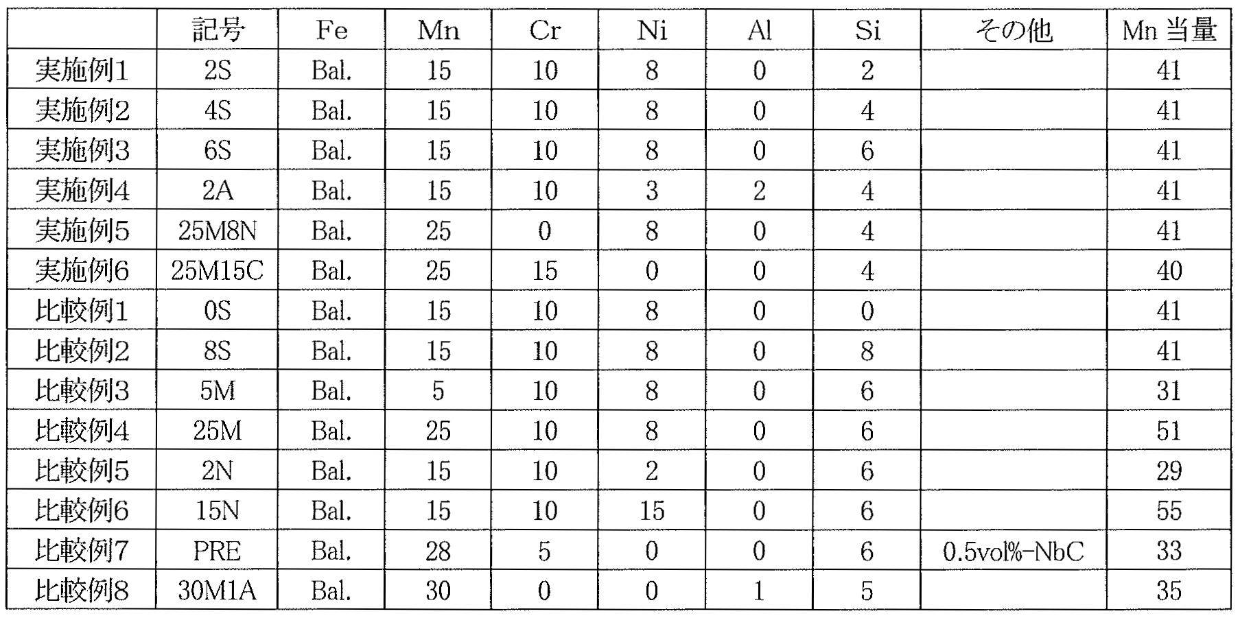
実施例1~6及び比較例1~8の各インゴットから、旋盤加工により平行部直径8mmでの低サイクル疲労試験片を作製し、室温大気中、0.1Hzの三角波、振幅1%のひずみ制御低サイクル疲労試験を行った。
図1は実施例2(4S)の引張圧縮変形第1サイクル目における応力とひずみの関係を示したものである。変形無しの状態Oから、引張ひずみを増加していくと、弾性変形OAに続いて塑性変形を生じ引張ひずみ1%のB点に至る。
その後変形が圧縮に反転されると、引張ひずみの減少に比例して引張弾性応力が低下する弾性変形部BCに続いて引張塑性歪みも減少していき、D点でひずみゼロとなる。
更に、圧縮変形が進むと圧縮塑性ひずみが発生する。圧縮ひずみが-1%のE点に達すると変形は再び圧縮から引張へと転じ、弾性変形EF、塑性変形FGと続いて第1サイクルが終了する。第2サイクル目は点線で表したGB’の曲線に沿って始まり、以降第1サイクルと同様の変形を繰り返す。
1サイクルの変形で応力-ひずみ曲線が描く面積に等しい仕事エネルギーが熱エネルギーに変換されて吸収され、振動を減衰する。
引張変形時、塑性変形が開始する点を0.2%耐力によって評価した。また、引張圧縮変形における応力振幅を図1に示すように引張側の最大応力から求めた。同様の評価を全ての実施例1~6及び比較例1~8の合金に対して行った。また図2は、実施例1(2S)、実施例2(4S)、実施例3(6S)及び比較例1(0S)、比較例3(5M)、比較例4(25M)、比較例5(2N)、比較例7((PRE)、比較例8(30M1A)の合金についての繰り返し引張圧縮変形による応力振幅の変化を示したものである。
多くの合金は、初期10サイクルで繰り返し硬化を示した後概ね安定した応力振幅を示す。しかし、5Mは10サイクル後も繰り返し硬化を示した。また、PREは初期硬化が小さく、10サイクルから200サイクルにかけて著しい硬化を示した後、安定な応力振幅となった。繰り返し引張圧縮変形による応力振幅の変化を評価するため、第100サイクル目の応力振幅(σa)を求め、以下式(4)により硬化率を計算した。
硬化率(H)=(σa100-σa1)/σa1 (4)
これらの結果から求められた、耐力、第1サイクル応力振幅、第100サイクル応力振幅、硬化率、最終繰り返し数を表2に示す。
これらの結果から求められた、耐力、第1サイクル応力振幅、第100サイクル応力振幅、硬化率、最終繰り返し数を表2に示す。
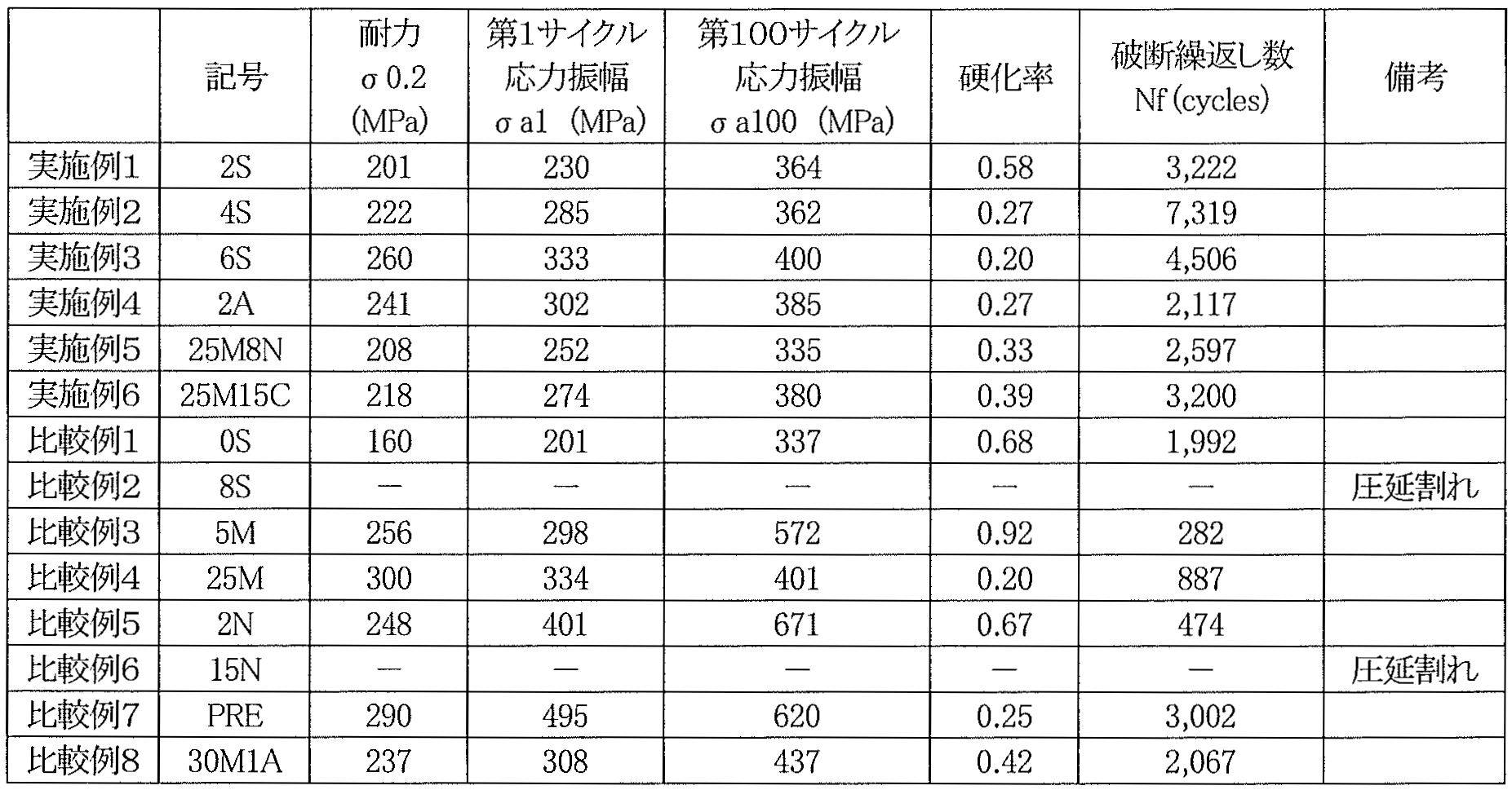
実施例1~6(2S、4S、6S、2A、25M8N、25M15C)はいずれも耐力が280MPa以下、第100サイクルの応力振幅が400MPa以下で、最終繰り返し数が2000サイクル以上である。Siを添加しない比較例1(0S)は破断繰り返し数が2000をわずかに下回った。
Siを本発明の成分範囲より多量に添加した比較例2(8S)は、圧延割れのため試料作製ができなかった。割れ発生は低融点の金属間化合物形成に起因すると考えられる。
Mn当量を31まで低下させた比較例3(5M)は、繰り返し硬化が著しく、破断繰り返し数も1000以下であった。繰り返し硬化は変形誘起されたα’マルテンサイト相に起因すると考えられる。
Mn当量を51まで増加させた比較例4(25M)は、変形によってεが形成しなくなるため破断繰り返し数が1000以下であった。
発明材よりもNiの添加量を低下させて2質量%とし、その結果Mn当量が29まで低下した比較例5(2N)は、繰り返し硬化が著しく高く、破断繰り返し数も1000以下であった。これは、50体積%以上のεマルテンサイト相とα’マルテンサイト相の形成のためと考えられる。
Niを15質量%と実施例よりも高濃度に含む比較例6(15N)は、熱間圧延時に割れが発生し、試験片の作製ができなかった。これはNiがSiとの低融点金属間化合物を形成したためであると考えられる。
比較例7(PRE)は特許文献5で開示されているNbC析出物添加型の制振合金である。破断繰り返し数が3000サイクル以上と優れているが、応力振幅が620MPaと極めて高い。
比較例8(30M1A)は特許文献6で開示されているAl添加制振合金である。破断繰り返し数が2000以上で応力振幅も低めであるが、Mnが30質量%も含まれるため量産化に適さない。
これらの結果から、本発明で規定した条件の実施例1~6の制振合金は、条件から外れた比較例1~8の合金に比べて、耐力と繰り返し引張圧縮変形後の応力振幅を低下させ、かつ破断繰り返し数を増加させて、長周期地震動後もメンテナンスフリーで使用可能で、かつ量産可能な制振合金であることが確認された。
本発明の制振合金を使用することにより、地震、風揺れ等による建築構造物の振動を抑制する弾塑性ダンパーとして、低応力で作動し、繰り返し大地震にさらされてもメンテナンスフリーで使用可能な低コスト制振装置を製造することが可能になる。
長周期地震動のように振幅が大きい揺れが長時間続いても制振性能を損なうことがない高性能ダンパーとして、特に高層ビルの制振に利用可能である。また、建築構造物としては、化学プラント、発電所、ホール、タワー、燃料タンク、高架鉄道・道路、橋梁、パイプライン、トンネル、風力発電設備などのあらゆる形態において、大ひずみで繰り返し変形される箇所の振動抑制に効果を発揮することが期待される。
Claims (5)
- 少なくともCr、Niのいずれかを含有するFe-Mn-(Cr、Ni)-Si系の制振合金、又はさらにAlを含有する制振合金であって、成分組成として、5質量%≦Mn≦28質量%、0質量%≦Cr≦15質量%、0質量%≦Ni<15質量%、0質量%<Si<6.5質量%、0質量%≦Al<3質量%、残部Fe及び不可避不純物を含有し、[%Ni]+0.5[%Mn]>0.75[%Cr]+1.125[%Si]+2[%Al]、かつ、37<[%Mn]+[%Cr]+2[%Ni]+5[%Al]<45(式中[%Ni]、[%Mn]、[%Cr]、[%Si]、[%Al]は、Ni、Mn、Cr、Si、Alの質量%を意味する)の条件を満足することを特徴とする制振合金。
- 10質量%≦Mn≦20質量%、2質量%≦Ni≦10質量%を含有することを特徴とする請求項1に記載の制振合金。
- 2質量%≦Si≦6質量%を含有することを特徴とする請求項1又は2に記載の制振合金。
- 塑性加工及び溶体化熱処理を施した後の合金の金属組織が、15体積%未満のεマルテンサイト相(HCP構造)、残部がγオーステナイト相(FCC構造)のみからなり、この状態からさらに、振幅1%の引張圧縮変形を100サイクル以上繰り返した後の状態が、50体積%未満のεマルテンサイト相、3体積%未満のα’マルテンサイト相、残部がγオーステナイト相であることを特徴とする請求項1から3のいずれか一項に記載の制振合金。
- 耐力が280MPa以下、振幅1%の引張圧縮変形を100サイクル以上繰り返した後の応力振幅が400MPa以下、かつ、破断繰り返し数が2000サイクル以上であることを特徴とする請求項1から4のいずれか一項に記載の制振合金。
Priority Applications (2)
| Application Number | Priority Date | Filing Date | Title |
|---|---|---|---|
| EP13869412.0A EP2940175B1 (en) | 2012-12-28 | 2013-12-19 | Damping alloy |
| KR1020157015190A KR102144708B1 (ko) | 2012-12-28 | 2013-12-19 | 제진합금 |
Applications Claiming Priority (2)
| Application Number | Priority Date | Filing Date | Title |
|---|---|---|---|
| JP2012287955A JP6182725B2 (ja) | 2012-12-28 | 2012-12-28 | 制振合金 |
| JP2012-287955 | 2012-12-28 |
Publications (1)
| Publication Number | Publication Date |
|---|---|
| WO2014103884A1 true WO2014103884A1 (ja) | 2014-07-03 |
Family
ID=51020971
Family Applications (1)
| Application Number | Title | Priority Date | Filing Date |
|---|---|---|---|
| PCT/JP2013/084119 Ceased WO2014103884A1 (ja) | 2012-12-28 | 2013-12-19 | 制振合金 |
Country Status (4)
| Country | Link |
|---|---|
| EP (1) | EP2940175B1 (ja) |
| JP (1) | JP6182725B2 (ja) |
| KR (1) | KR102144708B1 (ja) |
| WO (1) | WO2014103884A1 (ja) |
Cited By (2)
| Publication number | Priority date | Publication date | Assignee | Title |
|---|---|---|---|---|
| CN116292704A (zh) * | 2023-03-30 | 2023-06-23 | 上海材料研究所有限公司 | 一种能提供高阻尼力的抗疲劳弧形减震元件及应用 |
| CN117210756A (zh) * | 2023-10-12 | 2023-12-12 | 鞍钢集团北京研究院有限公司 | 一种超低屈强比低屈服点阻尼软钢及制备方法 |
Families Citing this family (7)
| Publication number | Priority date | Publication date | Assignee | Title |
|---|---|---|---|---|
| JP6696754B2 (ja) * | 2015-11-05 | 2020-05-20 | 株式会社ビー・ビー・エム | 構造物用複合制振ダンパー |
| JP2017193825A (ja) * | 2016-04-18 | 2017-10-26 | 株式会社ビービーエム | 座屈拘束型制振装置 |
| JP6887642B2 (ja) | 2017-04-04 | 2021-06-16 | 国立研究開発法人物質・材料研究機構 | 低サイクル疲労特性に優れるFe−Mn−Si系合金鋳造材 |
| JP7555733B2 (ja) | 2020-06-05 | 2024-09-25 | 株式会社竹中工務店 | 溶接組立鋼材 |
| EP4174204A4 (en) | 2020-06-24 | 2024-10-30 | National Institute for Materials Science | WELDED STRUCTURE AND ALLOY BASED ON FE-MN-CR-NI-SI |
| CN112029988B (zh) * | 2020-09-03 | 2022-02-18 | 成都科宁达材料有限公司 | 一种提高Fe-Cr-Mo基阻尼合金阻尼性能的方法 |
| KR20230073482A (ko) * | 2021-11-19 | 2023-05-26 | 한국재료연구원 | 고강도 고인성 중엔트로피 합금 및 그 제조 방법 |
Citations (10)
| Publication number | Priority date | Publication date | Assignee | Title |
|---|---|---|---|---|
| JPS62112751A (ja) * | 1985-11-09 | 1987-05-23 | Nippon Steel Corp | 鉄基形状記憶合金薄板・線の製造方法 |
| JPS6455361A (en) * | 1987-08-25 | 1989-03-02 | Takeshi Masumoto | Fe-base shape memory alloy |
| JPH0526274A (ja) | 1991-07-18 | 1993-02-02 | Kajima Corp | 弾塑性ダンパー |
| JPH05106367A (ja) | 1991-10-15 | 1993-04-27 | Kajima Corp | 鉛ダンパー |
| JPH05263858A (ja) | 1991-10-25 | 1993-10-12 | Honeywell Inc | 粘性ダンパー |
| JPH1036943A (ja) * | 1996-07-24 | 1998-02-10 | Taiheiyo Kinzoku Kk | Fe−Mn−Si系形状記憶合金の製造方法 |
| JP2001146855A (ja) | 1999-11-19 | 2001-05-29 | Shimizu Corp | 粘弾性ダンパー |
| JP2006194287A (ja) | 2005-01-11 | 2006-07-27 | National Institute For Materials Science | 鉄系形状記憶合金を用いた制振材料とこの材料を用いた制振・免震装置 |
| JP2008056987A (ja) | 2006-08-31 | 2008-03-13 | National Institute For Materials Science | 耐震合金 |
| JP2011214127A (ja) | 2010-03-31 | 2011-10-27 | Tk Techno Consulting:Kk | 制振・免震ダンパー装置 |
Family Cites Families (9)
| Publication number | Priority date | Publication date | Assignee | Title |
|---|---|---|---|---|
| JPH05186852A (ja) * | 1992-01-11 | 1993-07-27 | Sumitomo Metal Ind Ltd | 制振性鋼並びに制振性溶接鋼管とその製造法 |
| WO1997003215A1 (en) * | 1995-07-11 | 1997-01-30 | Kari Martti Ullakko | Iron-based shape memory and vibration damping alloys containing nitrogen |
| JP2003105438A (ja) * | 2001-09-27 | 2003-04-09 | National Institute For Materials Science | NbC添加Fe−Mn−Si系形状記憶合金の加工熱処理方法 |
| CN1158399C (zh) * | 2002-09-03 | 2004-07-21 | 四川大学 | 形变诱导时效型铁基形状记忆合金及其制备方法 |
| JP2009155719A (ja) * | 2007-12-25 | 2009-07-16 | Tk Techno Consulting:Kk | 制振性鋼管及びその製造方法 |
| JP2010043304A (ja) * | 2008-08-11 | 2010-02-25 | Daido Steel Co Ltd | Fe基制振合金 |
| JP2010156041A (ja) | 2008-12-04 | 2010-07-15 | Daido Steel Co Ltd | 双方向形状回復合金 |
| JP2012102391A (ja) | 2010-11-08 | 2012-05-31 | Tk Techno Consulting:Kk | 建造物外装材 |
| CN102435624B (zh) * | 2011-11-23 | 2013-10-30 | 天津大学 | 原位X射线衍射表征Fe-Mn-Si基记忆合金回复特性的方法 |
-
2012
- 2012-12-28 JP JP2012287955A patent/JP6182725B2/ja active Active
-
2013
- 2013-12-19 KR KR1020157015190A patent/KR102144708B1/ko active Active
- 2013-12-19 WO PCT/JP2013/084119 patent/WO2014103884A1/ja not_active Ceased
- 2013-12-19 EP EP13869412.0A patent/EP2940175B1/en active Active
Patent Citations (10)
| Publication number | Priority date | Publication date | Assignee | Title |
|---|---|---|---|---|
| JPS62112751A (ja) * | 1985-11-09 | 1987-05-23 | Nippon Steel Corp | 鉄基形状記憶合金薄板・線の製造方法 |
| JPS6455361A (en) * | 1987-08-25 | 1989-03-02 | Takeshi Masumoto | Fe-base shape memory alloy |
| JPH0526274A (ja) | 1991-07-18 | 1993-02-02 | Kajima Corp | 弾塑性ダンパー |
| JPH05106367A (ja) | 1991-10-15 | 1993-04-27 | Kajima Corp | 鉛ダンパー |
| JPH05263858A (ja) | 1991-10-25 | 1993-10-12 | Honeywell Inc | 粘性ダンパー |
| JPH1036943A (ja) * | 1996-07-24 | 1998-02-10 | Taiheiyo Kinzoku Kk | Fe−Mn−Si系形状記憶合金の製造方法 |
| JP2001146855A (ja) | 1999-11-19 | 2001-05-29 | Shimizu Corp | 粘弾性ダンパー |
| JP2006194287A (ja) | 2005-01-11 | 2006-07-27 | National Institute For Materials Science | 鉄系形状記憶合金を用いた制振材料とこの材料を用いた制振・免震装置 |
| JP2008056987A (ja) | 2006-08-31 | 2008-03-13 | National Institute For Materials Science | 耐震合金 |
| JP2011214127A (ja) | 2010-03-31 | 2011-10-27 | Tk Techno Consulting:Kk | 制振・免震ダンパー装置 |
Non-Patent Citations (6)
| Title |
|---|
| A. GLAGE; A. WEIDNER; H. BIERMANN: "Cyclic Deformation Behaviour of Three Austenite Cast CrMnNi TRIP/TWIP Steels with Various Ni Content", STEEL RESEARCH INTERNATIONAL, vol. 82, 2011, pages 1040 |
| B. C. MAJI; M. KRISHNAN; V. V. R. RAO: "The microstructure of an Fe-Mn-Si Cr-Ni stainless steel shape memory alloy", MET. MAT. TRANS. A, vol. 34A, 2003, pages 1029, XP001228300, DOI: doi:10.1007/s11661-003-0124-y |
| H. OTSUKA; H. YAMADA; T. MARUYAMA; H. TANAHASHI; S. MATSUDA; M. MURAKAMI: "Effects ofAlloying Additions on Fe-Mn-Si Shape Memory Alloys", ISIJ INTERNATIONAL, vol. 30, 1990, pages 674 |
| M. KOYAMA; M. MURAKAMI; K. OGAWA; T KIKUCHI; T SAWAGUCHI: "Influence ofAl on Shape Memory Effect and Twinning Induced Plasticity of Fe-Mn-Si-Al System Alloy", MATER. TRANS., 2007 |
| T. NIENDORF; F. RUBITSCHEK; H. J. MAIER; J. NIENDORF; H. A. RICHARD; A. FREHN: "Fatigue crack growth-Microstructure relationships in a high-manganese austenite TWIP steel", MATERIALS SCIENCE AND ENGINEERING A-STRUCTURAL MATERIALS PROPERTIES MICROSTRUCTURE AND PROCESSING, vol. 527, 2010, pages 2412 |
| T. SAWAGUCHI; P. SAHU; T KIKUCHI; K. OGAWA; S. KAJIWARA; A. KUSHIBE; M. HIGASHINO; T. OGAWA: "Vibration mitigation by the reversible fcc/hcp martensitic transformation during cyclic tension-compression loading of an Fe-Mn-Si-based shape memory alloy", SCRIPTA MATERIALIA, vol. 54, 2006, pages 1885, XP025028364, DOI: doi:10.1016/j.scriptamat.2006.02.013 |
Cited By (2)
| Publication number | Priority date | Publication date | Assignee | Title |
|---|---|---|---|---|
| CN116292704A (zh) * | 2023-03-30 | 2023-06-23 | 上海材料研究所有限公司 | 一种能提供高阻尼力的抗疲劳弧形减震元件及应用 |
| CN117210756A (zh) * | 2023-10-12 | 2023-12-12 | 鞍钢集团北京研究院有限公司 | 一种超低屈强比低屈服点阻尼软钢及制备方法 |
Also Published As
| Publication number | Publication date |
|---|---|
| JP6182725B2 (ja) | 2017-08-23 |
| KR102144708B1 (ko) | 2020-08-14 |
| KR20150117637A (ko) | 2015-10-20 |
| JP2014129567A (ja) | 2014-07-10 |
| EP2940175A1 (en) | 2015-11-04 |
| EP2940175A4 (en) | 2016-08-24 |
| EP2940175B1 (en) | 2021-02-03 |
Similar Documents
| Publication | Publication Date | Title |
|---|---|---|
| JP6182725B2 (ja) | 制振合金 | |
| RU2169786C2 (ru) | Азотсодержащие сплавы на основе железа, обладающие свойствами демпфирования и эффектом памяти формы | |
| JP5544633B2 (ja) | 衝撃吸収特性に優れた構造部材用オーステナイト系ステンレス鋼板 | |
| JP5837487B2 (ja) | 銅系合金及びそれを用いた構造材 | |
| CN101835917B (zh) | 高强度厚钢板及其制造方法 | |
| JP5597006B2 (ja) | 構造部材用高強度および高延性オーステナイト系ステンレス鋼板およびその製造方法 | |
| JP4926406B2 (ja) | 疲労き裂伝播特性に優れた鋼板 | |
| JP5385760B2 (ja) | 耐震性に優れた冷間成形角形鋼管 | |
| CN1227383C (zh) | 用作钢带的双相不锈钢带材 | |
| WO2011030853A1 (ja) | 高強度ボルト | |
| JP4984272B2 (ja) | 制振性に優れた鋼その製造方法及び該鋼を含んで構成される制振体 | |
| CN110468341A (zh) | 一种1400MPa级耐延迟断裂高强度螺栓及制造方法 | |
| JP4687712B2 (ja) | 高周波焼入れ中空駆動軸 | |
| JP2010121191A (ja) | 耐遅れ破壊特性および溶接性に優れる高強度厚鋼板およびその製造方法 | |
| KR102835321B1 (ko) | 용접 구조체 및 이것에 사용되는 Fe-Mn-Cr-Ni-Si계 합금 | |
| KR20140119216A (ko) | 고망간강 및 그 제조방법 | |
| JP2011214127A (ja) | 制振・免震ダンパー装置 | |
| JP2008163358A (ja) | 衝撃吸収特性に優れた構造部材用ステンレス鋼板 | |
| JP4709555B2 (ja) | 鉄系形状記憶合金を用いた制振材料とこの材料を用いた制振装置及び鉄合金系制振材料の使用方法 | |
| JP4066908B2 (ja) | 制震ダンパー用焼戻し鋼材およびその製造方法 | |
| CN117210756A (zh) | 一种超低屈强比低屈服点阻尼软钢及制备方法 | |
| KR102460872B1 (ko) | 저사이클 피로 특성이 우수한 Fe-Mn-Si계 합금 주조재 | |
| JP2008156752A (ja) | 衝撃吸収部材の製造方法 | |
| CN116334500B (zh) | 一种高强度抗疲劳弹塑性阻尼钢及其制造方法与应用 | |
| JP5375241B2 (ja) | 高強度薄鋼板およびその製造方法 |
Legal Events
| Date | Code | Title | Description |
|---|---|---|---|
| 121 | Ep: the epo has been informed by wipo that ep was designated in this application |
Ref document number: 13869412 Country of ref document: EP Kind code of ref document: A1 |
|
| DPE1 | Request for preliminary examination filed after expiration of 19th month from priority date (pct application filed from 20040101) | ||
| ENP | Entry into the national phase |
Ref document number: 20157015190 Country of ref document: KR Kind code of ref document: A |
|
| NENP | Non-entry into the national phase |
Ref country code: DE |
|
| WWE | Wipo information: entry into national phase |
Ref document number: 2013869412 Country of ref document: EP |