WO2014104018A1 - Générateur acoustique, dispositif de génération acoustique, et appareil électronique - Google Patents
Générateur acoustique, dispositif de génération acoustique, et appareil électronique Download PDFInfo
- Publication number
- WO2014104018A1 WO2014104018A1 PCT/JP2013/084489 JP2013084489W WO2014104018A1 WO 2014104018 A1 WO2014104018 A1 WO 2014104018A1 JP 2013084489 W JP2013084489 W JP 2013084489W WO 2014104018 A1 WO2014104018 A1 WO 2014104018A1
- Authority
- WO
- WIPO (PCT)
- Prior art keywords
- damping material
- sound generator
- diaphragm
- exciter
- sound
- Prior art date
- Legal status (The legal status is an assumption and is not a legal conclusion. Google has not performed a legal analysis and makes no representation as to the accuracy of the status listed.)
- Ceased
Links
Images


Classifications
-
- H—ELECTRICITY
- H04—ELECTRIC COMMUNICATION TECHNIQUE
- H04R—LOUDSPEAKERS, MICROPHONES, GRAMOPHONE PICK-UPS OR LIKE ACOUSTIC ELECTROMECHANICAL TRANSDUCERS; ELECTRIC HEARING AIDS; PUBLIC ADDRESS SYSTEMS
- H04R17/00—Piezoelectric transducers; Electrostrictive transducers
-
- H—ELECTRICITY
- H04—ELECTRIC COMMUNICATION TECHNIQUE
- H04R—LOUDSPEAKERS, MICROPHONES, GRAMOPHONE PICK-UPS OR LIKE ACOUSTIC ELECTROMECHANICAL TRANSDUCERS; ELECTRIC HEARING AIDS; PUBLIC ADDRESS SYSTEMS
- H04R1/00—Details of transducers, loudspeakers or microphones
- H04R1/06—Arranging circuit leads; Relieving strain on circuit leads
-
- H—ELECTRICITY
- H04—ELECTRIC COMMUNICATION TECHNIQUE
- H04R—LOUDSPEAKERS, MICROPHONES, GRAMOPHONE PICK-UPS OR LIKE ACOUSTIC ELECTROMECHANICAL TRANSDUCERS; ELECTRIC HEARING AIDS; PUBLIC ADDRESS SYSTEMS
- H04R7/00—Diaphragms for electromechanical transducers; Cones
- H04R7/02—Diaphragms for electromechanical transducers; Cones characterised by the construction
- H04R7/04—Plane diaphragms
- H04R7/045—Plane diaphragms using the distributed mode principle, i.e. whereby the acoustic radiation is emanated from uniformly distributed free bending wave vibration induced in a stiff panel and not from pistonic motion
Definitions
- the disclosed embodiment relates to a sound generator, a sound generation device, and an electronic apparatus.
- an acoustic generator using an actuator is known (see, for example, Patent Document 1).
- Such an acoustic generator outputs sound by vibrating a diaphragm by applying a voltage to an actuator attached to the diaphragm to vibrate.
- the frequency characteristics of the sound pressure have a peak (a portion where the sound pressure is higher than the surroundings) and a dip (the sound pressure is higher than the surroundings). There is a problem that it is difficult to obtain a high-quality sound quality.
- the sound generator and the electronic device provided with the sound generator have a problem that it is difficult to obtain good sound quality.
- One aspect of the embodiments has been made in view of the above, and an object thereof is to provide an acoustic generator, an acoustic generator, and an electronic apparatus that can obtain high-quality sound quality.
- An acoustic generator is provided with an exciter, the exciter attached thereto, a diaphragm that vibrates with the exciter by vibration of the exciter, and a first that suppresses vibration of the diaphragm.
- An acoustic generator having at least a damping material, wherein the thickness of the first damping material is larger than the thickness of the exciter.
- a sound generation device includes the sound generator described above and a housing that houses the sound generator.
- An electronic apparatus includes the above-described acoustic generator, an electronic circuit connected to the acoustic generator, and a housing that houses the electronic circuit and the acoustic generator. It has a function of generating sound from the sound generator.
- good sound quality can be obtained.
- FIG. 3A is a schematic plan view showing a configuration of a sound generator according to the embodiment
- FIG. 3B is a schematic cross-sectional view taken along line B-B ′ of FIG.
- A) is a schematic front view showing a specific arrangement example of the damping material (part 1)
- B) is a schematic front view showing a specific arrangement example of the damping material (part 2)
- (C) is a damping material.
- FIG. 3 It is a front schematic diagram (the 3) which shows the specific example of arrangement
- (A) is a figure which shows the structure of the acoustic generator which concerns on embodiment
- (B) is a figure which shows the structure of the electronic device which concerns on embodiment.
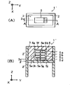
- FIG. 1A is a schematic plan view showing a schematic configuration of the acoustic generator 1 '
- FIG. 1B is a cross-sectional view taken along line A-A' of FIG. 1A.
- FIGS. 1A and 1B show a three-dimensional orthogonal coordinate system including a Z-axis having a vertically upward direction as a positive direction and a vertically downward direction as a negative direction. Such an orthogonal coordinate system may also be shown in other drawings used in the following description. Moreover, in FIG. 1A, illustration of the resin layer 7 is omitted.
- FIG. 1B shows the sound generator 1 'greatly exaggerated in the thickness direction (Z-axis direction).
- the sound generator 1 ′ includes a frame body 2, a diaphragm 3, and a piezoelectric element 5. As shown in FIG. 1A, in the following description, the case where there is one piezoelectric element 5 is illustrated unless otherwise specified, but the number of piezoelectric elements 5 is not limited.
- the frame body 2 is constituted by two frame members having the same shape of a rectangular frame shape, and functions as a support body that supports the diaphragm 3 with the peripheral edge of the diaphragm 3 interposed therebetween.
- the diaphragm 3 has a plate-like shape or a film-like shape, and a peripheral portion thereof is sandwiched and fixed between two frame members constituting the frame body 2. That is, the diaphragm 3 is supported in a state of being stretched in the frame of the frame body 2.
- the part located inside the frame 2 among the diaphragms 3, ie, the part which is not pinched by the frame 2 among the diaphragms 3, and can vibrate freely is made into the vibrating body 3a. Therefore, the vibrating body 3 a is a portion having a substantially rectangular shape in the frame of the frame body 2.
- the diaphragm 3 can be formed using various materials such as resin and metal.
- the diaphragm 3 can be composed of a resin film such as polyethylene or polyimide having a thickness of 10 to 200 ⁇ m.
- the thickness and material of the two frame members constituting the frame body 2 are not particularly limited.
- the frame 2 can be formed using various materials such as metal and resin.
- a stainless steel member having a thickness of 100 to 5000 ⁇ m can be suitably used as the two frame members constituting the frame body 2 because of its excellent mechanical strength and corrosion resistance.
- FIG. 1A shows the frame 2 in which the shape of the inner region is substantially rectangular, but it may be a polygon such as a parallelogram, trapezoid, or regular n-gon. In this embodiment, as shown to FIG. 1A, the example which is substantially rectangular shape is shown.
- the piezoelectric element 5 is provided by being attached to the surface (main surface) of the diaphragm 3 (vibrating body 3a), etc., and is vibrated by receiving a voltage applied by the input of an electric signal, thereby vibrating the diaphragm 3 (vibrating body 3a) is an exciter.
- the piezoelectric element 5 includes, for example, a laminate in which piezoelectric layers 5a, 5b, 5c, and 5d made of four ceramic layers and three internal electrode layers 5e are alternately laminated, Surface electrode layers 5f and 5g formed on the upper and lower surfaces of the laminate, and external electrodes 5h and 5j formed on the side surfaces where the internal electrode layer 5e is exposed.
- the lead terminals 6a and 6b are connected to the external electrodes 5h and 5j.
- the piezoelectric element 5 has a plate shape, and the main surface on the upper surface side and the lower surface side has a polygonal shape such as a rectangular shape or a square shape.
- the piezoelectric layers 5a, 5b, 5c, and 5d are polarized as shown by arrows in FIG. 1B. In other words, polarization is performed such that the direction of polarization with respect to the direction of the electric field applied at a certain moment is reversed between one side and the other side in the thickness direction (Z-axis direction in the figure).
- the main surface of the piezoelectric element 5 is bonded to the main surface of the diaphragm 3 (vibrating body 3a) with an adhesive such as an epoxy resin.
- non-lead piezoelectric materials such as lead zirconate titanate, Bi layered compounds, tungsten bronze structure compounds, etc. have been conventionally used.
- the used piezoelectric ceramics can be used.
- various metal materials can be used as the material of the internal electrode layer 5e.
- the piezoelectric layers 5a, 5b, 5c, and 5d are contained, the piezoelectric layers 5a, 5b, 5c, and 5d and the internal electrode layer 5e Since the stress due to the difference in thermal expansion can be reduced, the piezoelectric element 5 free from stacking faults can be obtained.
- the lead terminals 6a and 6b can be formed using various metal materials. For example, if the lead terminals 6a and 6b are configured using flexible wiring in which a metal foil such as copper or aluminum is sandwiched between resin films, the height of the piezoelectric element 5 can be reduced.
- the sound generator 1 ′ is arranged so as to cover the surfaces of the piezoelectric element 5 and the vibrating body 3a in the frame of the frame 2, and the vibration plate 3 (vibrating body 3a) and the piezoelectric element are arranged.
- a resin layer 7 integrated with the element 5 is further provided.
- the resin layer 7 is preferably formed using, for example, an acrylic resin so that the Young's modulus is in the range of 1 MPa to 1 GPa.
- an appropriate damping effect can be induced by embedding the piezoelectric element 5 with the resin layer 7, the resonance phenomenon can be suppressed and the peak or dip in the frequency characteristic of the sound pressure can be suppressed to a small level. .
- FIG. 1B shows a state in which the resin layer 7 is formed so as to be the same height as the frame 2, but it is sufficient that the piezoelectric element 5 is embedded, for example, the resin layer 7 has a frame. It may be formed to be higher than the height of the body 2.
- a bimorph type stacked piezoelectric element is taken as an example, but the present invention is not limited to this.
- a unimorph type in which the expanding and contracting piezoelectric element 5 is attached to the diaphragm 3 (vibrating body 3a) may be used.
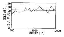
- the acoustic generator of this example has the piezoelectric element 5 attached to the vibrating body 3a and covered with the resin layer 7, so that the vibrating body 3a, the piezoelectric element 5 and the resin layer are covered. 7 is integrated, and the vibrating body 3a, the piezoelectric element 5 and the resin layer 7 vibrate integrally.
- Such frequency-sound pressure characteristics are illustrated in FIG.
- the first damping material having a thickness larger than the thickness of the piezoelectric element 5 is used. We decided to provide it.
- the maximum amplitude distance of the first damping material becomes larger than the amplitude distance of the piezoelectric element 5 and the load increases, and the vibration of the first damping material is delayed, so that the noise can be further attenuated.
- FIG. 3A is a schematic plan view showing a configuration of the sound generator 1 according to the embodiment
- FIG. 3B is a schematic cross-sectional view taken along line B-B ′ shown in FIG. 3A
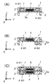
- 4A to 4C are schematic front views (No. 1) to (No. 3) of the damping material 8 as viewed from the front.
- the sound generator 1 includes a first damping material 81 as the damping material 8 in addition to the sound generator 1 'shown in FIGS. 1A and 1B.
- the first damping material 81 is attached to the same principal surface as the principal surface of the diaphragm 3 to which the piezoelectric element 5 is attached.
- FIG. 3A illustrates the case where one rectangular first damping material 81 is disposed on one main surface of the diaphragm 3 (vibrating body 3a), but the shape, number, and arrangement thereof are illustrated. The area is not limited.
- the thickness of the first damping material 81 is different from the thickness of the piezoelectric element 5.
- the thickness of the first damping material 81 is thicker than the thickness of the piezoelectric element 5. Since the thickness of the first damping material 81 is thicker than the thickness of the piezoelectric element 5, when the first damping material 81 vibrates following the vibration of the piezoelectric element 5, the maximum amplitude distance of the first damping material 81 is piezoelectric. Since it becomes larger than the amplitude distance of an element, a load becomes large. Further, the vibration of the first damping material 81 is delayed. Therefore, the first damping material 81 dampens vibrations in the thickness direction of the piezoelectric element 5 to further attenuate noise, and as a result, better sound quality can be obtained. In particular, since high-frequency and high-temperature noise can be suppressed, an unpleasant metallic sound can be attenuated.
- the first damping material 81 preferably has regions with different thicknesses.
- having regions with different thicknesses means that the thickness of the first damping material 81 is not uniform throughout, but the surface is inclined from one end side to the other end side, or the surface is stepped. And a state where the concave and convex portions are alternately arranged are shown.
- the thickness of the first damping material 81 includes the regions having different thicknesses, it is possible to prevent the vibration from being synchronized between both ends of the first damping material 81 and to weaken the vibration in the thickness direction. As a result, the generation of noise can be further suppressed.
- FIGS. 4A to 4C it is preferable that there are two or more damping materials 8.
- a second damping material 82 is further provided, and the second damping material 82 is attached to the main surface of the diaphragm 3.
- vibrations in the thickness direction of the piezoelectric element 5 can be more easily damped.
- the plurality of damping materials 8 have different thicknesses.
- the first damping material 81 and the second damping material 82 are preferably different in thickness.
- the two damping materials 8 are the same as one main surface on which the piezoelectric element 5 of the diaphragm 3 (vibrating body 3a) is disposed.
- the main surface an example is shown in which the piezoelectric elements 5 are arranged opposite to each other.
- damping materials 8 are respectively connected to different main surfaces (one main surface and the other main surface) of the diaphragm 3 (vibrating body 3a).
- An example of arrangement is shown in FIG.
- any of the damping materials 8 is thicker than the thickness of the piezoelectric element 4 (exciter).
- the material 81 only needs to be thicker than the piezoelectric element 5 (exciter), and the second damping material 82 may be thinner than the piezoelectric element 5.
- FIG. 4C shows two damping materials 8 (first damping material 81 and second damping material 82) when the bimorph type piezoelectric element 5 is attached with the diaphragm 3 sandwiched from both sides. These show examples of arrangement on different main surfaces of the diaphragm 3 (vibrating body 3a). As shown in FIG. 4C, not only the thickness of the first damping material 81 is larger than the thickness of the piezoelectric element 5 attached to one main surface of the diaphragm 3, but also the other main surface of the diaphragm 3. The thickness of the second damping material 82 is greater than the thickness of the piezoelectric element 5 attached to the piezoelectric element 5.
- damping material 8 (the first damping material 81 and the second damping material 82) vibrates in the thickness direction of the piezoelectric element 5. It is effective in that noise can be attenuated by damping noise and a higher quality sound can be obtained.
- the 1st damping material 81 showed the example of one, multiple may be provided.
- the fact that a plurality of first damping materials 81 are provided means that a plurality of damping materials having the same shape are provided.
- one example of the second damping material 82 is shown, but a plurality of second damping materials 82 may be provided.
- the fact that a plurality of second damping materials 82 are provided means that a plurality of damping materials having the same shape are provided.
- damping materials 8 may have any mechanical loss, but are desirably members having a high mechanical loss factor, in other words, a low mechanical quality factor (so-called mechanical Q).
- Such a damping material 8 can be formed using various elastic bodies, for example, but since it is desirable that it is soft and easily deformed, it can be suitably formed using a rubber material such as urethane rubber. In particular, a porous rubber material such as urethane foam can be suitably used.
- the first damping material 81 is attached to the vibration plate 3 (vibrating body 3a), and is covered with the resin layer 7 together with the piezoelectric element 5 and the vibrating plate 3 (vibrating body 3a). Has been.
- the thickness of the first damping material 81 is set to be larger than the thickness of the piezoelectric element 5 as described above, when the piezoelectric element 5 vibrates, the piezoelectric element 5 and the first damping material 81 are in the thickness direction. Resonance is prevented and the generation of noise due to these resonances is suppressed, and as a result, a good sound quality with reduced noise can be obtained.
- the first damping material 81 and the second damping material 82 are attached to the diaphragm 3 (vibrating body 3a), and the resin together with the piezoelectric element 5 and the diaphragm 3 (vibrating body 3a). Covered by layer 7 and integrated.
- the thickness of the first damping material 81 and the second damping material 82 is set to be larger than the thickness of the piezoelectric element 5 as described above, the piezoelectric element 5 and the first damping material when the piezoelectric element 5 vibrates. 81 and the second damping material 82 are further prevented from resonating in the thickness direction, and the generation of noise due to these resonances is further suppressed. As a result, a high-quality sound quality with further reduced noise can be obtained.
- the plurality of damping materials 8 may have different shapes, different shapes, different materials, different areas, and different masses.
- the damping material 8 may be disposed on one main surface of the diaphragm 3 (vibrating body 3a) and then in contact with the piezoelectric element 5 or the frame body 2. Further, the damping material 8 is not only attached to one main surface of the diaphragm 3 (vibrating body 3a), but may be embedded in the resin layer 7 with a space from the diaphragm 3 (vibrating body 3a).
- FIG. 5A is a diagram illustrating a configuration of the sound generation device 20 according to the embodiment
- FIG. 5B is a diagram illustrating a configuration of the electronic device 50 according to the embodiment.
- FIG. 5A is a diagram illustrating a configuration of the sound generation device 20 according to the embodiment
- FIG. 5B is a diagram illustrating a configuration of the electronic device 50 according to the embodiment.
- only the component required for description is shown and description about a general component is abbreviate
- the sound generator 20 is a sound generation device such as a so-called speaker, and includes, for example, a sound generator 1 and a housing 30 that houses the sound generator 1 as shown in FIG. 5A.
- the housing 30 resonates the sound generated by the sound generator 1 and radiates the sound to the outside through an opening (not shown) formed in the housing 30.
- the sound pressure in a low frequency band can be increased.
- the sound generator 1 can be mounted on various electronic devices 50.
- the electronic device 50 is a mobile terminal device such as a mobile phone or a tablet terminal.
- the electronic device 50 includes an electronic circuit 60.
- the electronic circuit 60 includes, for example, a controller 50a, a transmission / reception unit 50b, a key input unit 50c, and a microphone input unit 50d.
- the electronic circuit 60 is connected to the sound generator 1 and has a function of outputting an audio signal to the sound generator.
- the sound generator generates sound based on the sound signal input from the electronic circuit.
- the electronic device 50 includes a display unit 50e, an antenna 50f, and the sound generator 1. Further, the electronic device 50 includes a housing 40 that accommodates these devices.
- 5B shows a state in which all devices including the controller 50a are accommodated in one casing 40, but the accommodation form of each device is not limited. In the present embodiment, it is sufficient that at least the electronic circuit 60 and the sound generator 1 are accommodated in one housing 40.
- the controller 50 a is a control unit of the electronic device 50.
- the transmission / reception unit 50b transmits / receives data via the antenna 50f based on the control of the controller 50a.
- the key input unit 50c is an input device of the electronic device 50 and accepts a key input operation by an operator.
- the microphone input unit 50d is also an input device of the electronic device 50, and accepts a voice input operation by an operator.
- the display unit 50e is a display output device of the electronic device 50, and outputs display information based on the control of the controller 50a.
- the sound generator 1 operates as a sound output device in the electronic device 50.
- the sound generator 1 is connected to the controller 50a of the electronic circuit 60, and emits sound upon application of a voltage controlled by the controller 50a.
- the electronic device 50 is described as a portable terminal device.
- the electronic device 50 is not limited to the type of the electronic device 50, and may be applied to various consumer devices having a function of emitting sound.
- flat-screen TVs and car audio devices can of course be used for products having a function of emitting sound such as "speak", for example, various products such as vacuum cleaners, washing machines, refrigerators, microwave ovens, etc. .
- the piezoelectric element 5 is provided on one main surface of the vibrating body 3a.
- the present invention is not limited to this, and the vibration element 3a is provided on both surfaces.
- a piezoelectric element 5 may be provided.
- the shape of the inner region of the frame is a substantially rectangular shape is taken as an example, and it may be a polygon, but is not limited thereto, and is not limited to a circle or an ellipse. It may be a shape.
- the resin layer 7 is formed so as to cover the piezoelectric element 5 and the vibrating body 3a in the frame of the frame body 2 is taken as an example.
- a resin layer is not necessarily formed. Also good.
- the diaphragm is configured by a thin film such as a resin film
- the present invention is not limited to this.
- the diaphragm may be configured by a plate-like member.
- the support body that supports the vibrating body 3a is the frame body 2 and supports the periphery of the vibrating body 3a has been described as an example, but the present invention is not limited thereto. For example, it is good also as supporting only the both ends of the longitudinal direction or the transversal direction of the vibrating body 3a.
- the exciter is the piezoelectric element 5
- the exciter is not limited to the piezoelectric element, and a function that vibrates when an electric signal is input thereto. As long as it has.
- an electrodynamic exciter, an electrostatic exciter, or an electromagnetic exciter well known as an exciter for vibrating a speaker may be used.
- the electrodynamic exciter is such that an electric current is passed through a coil disposed between the magnetic poles of a permanent magnet to vibrate the coil.
- the electrostatic exciter is composed of two metals facing each other. A bias and an electric signal are passed through the plate to vibrate the metal plate, and an electromagnetic exciter is an electric signal that is passed through the coil to vibrate a thin iron plate.
Landscapes
- Physics & Mathematics (AREA)
- Engineering & Computer Science (AREA)
- Acoustics & Sound (AREA)
- Signal Processing (AREA)
- Piezo-Electric Transducers For Audible Bands (AREA)
Abstract
L'invention a pour objectif d'obtenir une qualité sonore satisfaisante présentant peu de bruit. Le générateur acoustique de l'invention est équipé au moins d'un excitateur, d'un diaphragme et d'un premier matériau d'amortissement. Ledit excitateur vibre par entrée de signaux électriques. Un corps vibrant sur lequel est installé l'excitateur, vibre avec ce dernier au gré des vibrations du générateur acoustique. Ledit premier matériau d'amortissement limite ces vibrations, et son épaisseur est supérieure à celle dudit excitateur.
Applications Claiming Priority (2)
| Application Number | Priority Date | Filing Date | Title |
|---|---|---|---|
| JP2012283046 | 2012-12-26 | ||
| JP2012-283046 | 2012-12-26 |
Publications (1)
| Publication Number | Publication Date |
|---|---|
| WO2014104018A1 true WO2014104018A1 (fr) | 2014-07-03 |
Family
ID=51021099
Family Applications (1)
| Application Number | Title | Priority Date | Filing Date |
|---|---|---|---|
| PCT/JP2013/084489 Ceased WO2014104018A1 (fr) | 2012-12-26 | 2013-12-24 | Générateur acoustique, dispositif de génération acoustique, et appareil électronique |
Country Status (1)
| Country | Link |
|---|---|
| WO (1) | WO2014104018A1 (fr) |
Cited By (2)
| Publication number | Priority date | Publication date | Assignee | Title |
|---|---|---|---|---|
| CN113390969A (zh) * | 2021-06-17 | 2021-09-14 | 广东奥迪威传感科技股份有限公司 | 一种传感器 |
| EP3962107A2 (fr) * | 2020-08-31 | 2022-03-02 | LG Display Co., Ltd. | Appareil de vibration et appareil le comprenant |
Citations (3)
| Publication number | Priority date | Publication date | Assignee | Title |
|---|---|---|---|---|
| JP2006332861A (ja) * | 2005-05-24 | 2006-12-07 | Inax Corp | スピーカ装置、スピーカ付き作業口蓋及びスピーカ付き壁パネル |
| JP2010199818A (ja) * | 2009-02-24 | 2010-09-09 | Panasonic Corp | 平板スピーカ |
| JP2012110018A (ja) * | 2010-06-25 | 2012-06-07 | Kyocera Corp | 音響発生器 |
-
2013
- 2013-12-24 WO PCT/JP2013/084489 patent/WO2014104018A1/fr not_active Ceased
Patent Citations (3)
| Publication number | Priority date | Publication date | Assignee | Title |
|---|---|---|---|---|
| JP2006332861A (ja) * | 2005-05-24 | 2006-12-07 | Inax Corp | スピーカ装置、スピーカ付き作業口蓋及びスピーカ付き壁パネル |
| JP2010199818A (ja) * | 2009-02-24 | 2010-09-09 | Panasonic Corp | 平板スピーカ |
| JP2012110018A (ja) * | 2010-06-25 | 2012-06-07 | Kyocera Corp | 音響発生器 |
Cited By (3)
| Publication number | Priority date | Publication date | Assignee | Title |
|---|---|---|---|---|
| EP3962107A2 (fr) * | 2020-08-31 | 2022-03-02 | LG Display Co., Ltd. | Appareil de vibration et appareil le comprenant |
| CN113390969A (zh) * | 2021-06-17 | 2021-09-14 | 广东奥迪威传感科技股份有限公司 | 一种传感器 |
| CN113390969B (zh) * | 2021-06-17 | 2025-10-24 | 广东奥迪威传感科技股份有限公司 | 一种传感器 |
Similar Documents
| Publication | Publication Date | Title |
|---|---|---|
| JP6016945B2 (ja) | 音響発生器、音響発生装置および電子機器 | |
| JP5627824B1 (ja) | 音響発生器、音響発生装置および電子機器 | |
| JP6053794B2 (ja) | 音響発生器、音響発生装置および電子機器 | |
| WO2014050983A1 (fr) | Générateur acoustique, dispositif de génération acoustique et appareil électronique | |
| WO2014097668A1 (fr) | Générateur acoustique, dispositif de génération acoustique et dispositif électronique | |
| JP5602978B2 (ja) | 音響発生器、音響発生装置および電子機器 | |
| JP5934386B2 (ja) | 音響発生器、音響発生装置および電子機器 | |
| JP6166038B2 (ja) | 音響発生器、音響発生装置および電子機器 | |
| JP2014127767A (ja) | 音響発生器、音響発生装置および電子機器 | |
| JP5909169B2 (ja) | 音響発生器、音響発生装置および電子機器 | |
| WO2014104018A1 (fr) | Générateur acoustique, dispositif de génération acoustique, et appareil électronique | |
| JP6034182B2 (ja) | 音響発生器、音響発生装置および電子機器 | |
| JP6027827B2 (ja) | 音響発生器、音響発生装置および電子機器 | |
| JP2014123812A (ja) | 音響発生器、音響発生装置および電子機器 | |
| JP5952426B2 (ja) | 音響発生器、音響発生装置および電子機器 | |
| JP2014123900A (ja) | 音響発生器、音響発生装置および電子機器 | |
| JP6017950B2 (ja) | 音響発生器、音響発生装置および電子機器 | |
| JP6092618B2 (ja) | 音響発生器、音響発生装置および電子機器 | |
| JP5871751B2 (ja) | 音響発生器、音響発生装置および電子機器 | |
| WO2014091813A1 (fr) | Générateur acoustique, dispositif de génération acoustique et dispositif électronique | |
| WO2014103427A1 (fr) | Générateur sonore, appareil de génération sonore et appareil électronique | |
| JP2014131119A (ja) | 音響発生器、音響発生装置および電子機器 | |
| JP2014116795A (ja) | 音響発生器、音響発生装置および電子機器 |
Legal Events
| Date | Code | Title | Description |
|---|---|---|---|
| 121 | Ep: the epo has been informed by wipo that ep was designated in this application |
Ref document number: 13867000 Country of ref document: EP Kind code of ref document: A1 |
|
| NENP | Non-entry into the national phase |
Ref country code: DE |
|
| 122 | Ep: pct application non-entry in european phase |
Ref document number: 13867000 Country of ref document: EP Kind code of ref document: A1 |
|
| NENP | Non-entry into the national phase |
Ref country code: JP |