WO2014104132A1 - 円錐ころ軸受 - Google Patents
円錐ころ軸受 Download PDFInfo
- Publication number
- WO2014104132A1 WO2014104132A1 PCT/JP2013/084751 JP2013084751W WO2014104132A1 WO 2014104132 A1 WO2014104132 A1 WO 2014104132A1 JP 2013084751 W JP2013084751 W JP 2013084751W WO 2014104132 A1 WO2014104132 A1 WO 2014104132A1
- Authority
- WO
- WIPO (PCT)
- Prior art keywords
- diameter
- tapered roller
- roller bearing
- ring
- inner ring
- Prior art date
- Legal status (The legal status is an assumption and is not a legal conclusion. Google has not performed a legal analysis and makes no representation as to the accuracy of the status listed.)
- Ceased
Links
Images






Classifications
-
- F—MECHANICAL ENGINEERING; LIGHTING; HEATING; WEAPONS; BLASTING
- F16—ENGINEERING ELEMENTS AND UNITS; GENERAL MEASURES FOR PRODUCING AND MAINTAINING EFFECTIVE FUNCTIONING OF MACHINES OR INSTALLATIONS; THERMAL INSULATION IN GENERAL
- F16C—SHAFTS; FLEXIBLE SHAFTS; ELEMENTS OR CRANKSHAFT MECHANISMS; ROTARY BODIES OTHER THAN GEARING ELEMENTS; BEARINGS
- F16C33/00—Parts of bearings; Special methods for making bearings or parts thereof
- F16C33/30—Parts of ball or roller bearings
- F16C33/46—Cages for rollers or needles
- F16C33/4605—Details of interaction of cage and race, e.g. retention or centring
-
- F—MECHANICAL ENGINEERING; LIGHTING; HEATING; WEAPONS; BLASTING
- F16—ENGINEERING ELEMENTS AND UNITS; GENERAL MEASURES FOR PRODUCING AND MAINTAINING EFFECTIVE FUNCTIONING OF MACHINES OR INSTALLATIONS; THERMAL INSULATION IN GENERAL
- F16C—SHAFTS; FLEXIBLE SHAFTS; ELEMENTS OR CRANKSHAFT MECHANISMS; ROTARY BODIES OTHER THAN GEARING ELEMENTS; BEARINGS
- F16C19/00—Bearings with rolling contact, for exclusively rotary movement
- F16C19/22—Bearings with rolling contact, for exclusively rotary movement with bearing rollers essentially of the same size in one or more circular rows, e.g. needle bearings
- F16C19/34—Bearings with rolling contact, for exclusively rotary movement with bearing rollers essentially of the same size in one or more circular rows, e.g. needle bearings for both radial and axial load
- F16C19/36—Bearings with rolling contact, for exclusively rotary movement with bearing rollers essentially of the same size in one or more circular rows, e.g. needle bearings for both radial and axial load with a single row of rollers
- F16C19/364—Bearings with rolling contact, for exclusively rotary movement with bearing rollers essentially of the same size in one or more circular rows, e.g. needle bearings for both radial and axial load with a single row of rollers with tapered rollers, i.e. rollers having essentially the shape of a truncated cone
-
- F—MECHANICAL ENGINEERING; LIGHTING; HEATING; WEAPONS; BLASTING
- F16—ENGINEERING ELEMENTS AND UNITS; GENERAL MEASURES FOR PRODUCING AND MAINTAINING EFFECTIVE FUNCTIONING OF MACHINES OR INSTALLATIONS; THERMAL INSULATION IN GENERAL
- F16C—SHAFTS; FLEXIBLE SHAFTS; ELEMENTS OR CRANKSHAFT MECHANISMS; ROTARY BODIES OTHER THAN GEARING ELEMENTS; BEARINGS
- F16C33/00—Parts of bearings; Special methods for making bearings or parts thereof
- F16C33/30—Parts of ball or roller bearings
- F16C33/46—Cages for rollers or needles
- F16C33/4617—Massive or moulded cages having cage pockets surrounding the rollers, e.g. machined window cages
- F16C33/4623—Massive or moulded cages having cage pockets surrounding the rollers, e.g. machined window cages formed as one-piece cages, i.e. monoblock cages
- F16C33/4635—Massive or moulded cages having cage pockets surrounding the rollers, e.g. machined window cages formed as one-piece cages, i.e. monoblock cages made from plastic, e.g. injection moulded window cages
-
- F—MECHANICAL ENGINEERING; LIGHTING; HEATING; WEAPONS; BLASTING
- F16—ENGINEERING ELEMENTS AND UNITS; GENERAL MEASURES FOR PRODUCING AND MAINTAINING EFFECTIVE FUNCTIONING OF MACHINES OR INSTALLATIONS; THERMAL INSULATION IN GENERAL
- F16C—SHAFTS; FLEXIBLE SHAFTS; ELEMENTS OR CRANKSHAFT MECHANISMS; ROTARY BODIES OTHER THAN GEARING ELEMENTS; BEARINGS
- F16C33/00—Parts of bearings; Special methods for making bearings or parts thereof
- F16C33/30—Parts of ball or roller bearings
- F16C33/46—Cages for rollers or needles
- F16C33/467—Details of individual pockets, e.g. shape or roller retaining means
- F16C33/4676—Details of individual pockets, e.g. shape or roller retaining means of the stays separating adjacent cage pockets, e.g. guide means for the bearing-surface of the rollers
-
- F—MECHANICAL ENGINEERING; LIGHTING; HEATING; WEAPONS; BLASTING
- F16—ENGINEERING ELEMENTS AND UNITS; GENERAL MEASURES FOR PRODUCING AND MAINTAINING EFFECTIVE FUNCTIONING OF MACHINES OR INSTALLATIONS; THERMAL INSULATION IN GENERAL
- F16C—SHAFTS; FLEXIBLE SHAFTS; ELEMENTS OR CRANKSHAFT MECHANISMS; ROTARY BODIES OTHER THAN GEARING ELEMENTS; BEARINGS
- F16C33/00—Parts of bearings; Special methods for making bearings or parts thereof
- F16C33/30—Parts of ball or roller bearings
- F16C33/58—Raceways; Race rings
- F16C33/583—Details of specific parts of races
-
- F—MECHANICAL ENGINEERING; LIGHTING; HEATING; WEAPONS; BLASTING
- F16—ENGINEERING ELEMENTS AND UNITS; GENERAL MEASURES FOR PRODUCING AND MAINTAINING EFFECTIVE FUNCTIONING OF MACHINES OR INSTALLATIONS; THERMAL INSULATION IN GENERAL
- F16C—SHAFTS; FLEXIBLE SHAFTS; ELEMENTS OR CRANKSHAFT MECHANISMS; ROTARY BODIES OTHER THAN GEARING ELEMENTS; BEARINGS
- F16C33/00—Parts of bearings; Special methods for making bearings or parts thereof
- F16C33/30—Parts of ball or roller bearings
- F16C33/58—Raceways; Race rings
- F16C33/583—Details of specific parts of races
- F16C33/585—Details of specific parts of races of raceways, e.g. ribs to guide the rollers
-
- F—MECHANICAL ENGINEERING; LIGHTING; HEATING; WEAPONS; BLASTING
- F16—ENGINEERING ELEMENTS AND UNITS; GENERAL MEASURES FOR PRODUCING AND MAINTAINING EFFECTIVE FUNCTIONING OF MACHINES OR INSTALLATIONS; THERMAL INSULATION IN GENERAL
- F16C—SHAFTS; FLEXIBLE SHAFTS; ELEMENTS OR CRANKSHAFT MECHANISMS; ROTARY BODIES OTHER THAN GEARING ELEMENTS; BEARINGS
- F16C33/00—Parts of bearings; Special methods for making bearings or parts thereof
- F16C33/30—Parts of ball or roller bearings
- F16C33/58—Raceways; Race rings
- F16C33/583—Details of specific parts of races
- F16C33/586—Details of specific parts of races outside the space between the races, e.g. end faces or bore of inner ring
-
- F—MECHANICAL ENGINEERING; LIGHTING; HEATING; WEAPONS; BLASTING
- F16—ENGINEERING ELEMENTS AND UNITS; GENERAL MEASURES FOR PRODUCING AND MAINTAINING EFFECTIVE FUNCTIONING OF MACHINES OR INSTALLATIONS; THERMAL INSULATION IN GENERAL
- F16C—SHAFTS; FLEXIBLE SHAFTS; ELEMENTS OR CRANKSHAFT MECHANISMS; ROTARY BODIES OTHER THAN GEARING ELEMENTS; BEARINGS
- F16C33/00—Parts of bearings; Special methods for making bearings or parts thereof
- F16C33/30—Parts of ball or roller bearings
- F16C33/66—Special parts or details in view of lubrication
- F16C33/6603—Special parts or details in view of lubrication with grease as lubricant
- F16C33/6607—Retaining the grease in or near the bearing
- F16C33/6614—Retaining the grease in or near the bearing in recesses or cavities provided in retainers, races or rolling elements
-
- F—MECHANICAL ENGINEERING; LIGHTING; HEATING; WEAPONS; BLASTING
- F16—ENGINEERING ELEMENTS AND UNITS; GENERAL MEASURES FOR PRODUCING AND MAINTAINING EFFECTIVE FUNCTIONING OF MACHINES OR INSTALLATIONS; THERMAL INSULATION IN GENERAL
- F16C—SHAFTS; FLEXIBLE SHAFTS; ELEMENTS OR CRANKSHAFT MECHANISMS; ROTARY BODIES OTHER THAN GEARING ELEMENTS; BEARINGS
- F16C33/00—Parts of bearings; Special methods for making bearings or parts thereof
- F16C33/30—Parts of ball or roller bearings
- F16C33/66—Special parts or details in view of lubrication
- F16C33/6637—Special parts or details in view of lubrication with liquid lubricant
- F16C33/664—Retaining the liquid in or near the bearing
- F16C33/6651—Retaining the liquid in or near the bearing in recesses or cavities provided in retainers, races or rolling elements
-
- F—MECHANICAL ENGINEERING; LIGHTING; HEATING; WEAPONS; BLASTING
- F16—ENGINEERING ELEMENTS AND UNITS; GENERAL MEASURES FOR PRODUCING AND MAINTAINING EFFECTIVE FUNCTIONING OF MACHINES OR INSTALLATIONS; THERMAL INSULATION IN GENERAL
- F16C—SHAFTS; FLEXIBLE SHAFTS; ELEMENTS OR CRANKSHAFT MECHANISMS; ROTARY BODIES OTHER THAN GEARING ELEMENTS; BEARINGS
- F16C2240/00—Specified values or numerical ranges of parameters; Relations between them
- F16C2240/30—Angles, e.g. inclinations
-
- F—MECHANICAL ENGINEERING; LIGHTING; HEATING; WEAPONS; BLASTING
- F16—ENGINEERING ELEMENTS AND UNITS; GENERAL MEASURES FOR PRODUCING AND MAINTAINING EFFECTIVE FUNCTIONING OF MACHINES OR INSTALLATIONS; THERMAL INSULATION IN GENERAL
- F16C—SHAFTS; FLEXIBLE SHAFTS; ELEMENTS OR CRANKSHAFT MECHANISMS; ROTARY BODIES OTHER THAN GEARING ELEMENTS; BEARINGS
- F16C2240/00—Specified values or numerical ranges of parameters; Relations between them
- F16C2240/30—Angles, e.g. inclinations
- F16C2240/34—Contact angles
-
- F—MECHANICAL ENGINEERING; LIGHTING; HEATING; WEAPONS; BLASTING
- F16—ENGINEERING ELEMENTS AND UNITS; GENERAL MEASURES FOR PRODUCING AND MAINTAINING EFFECTIVE FUNCTIONING OF MACHINES OR INSTALLATIONS; THERMAL INSULATION IN GENERAL
- F16C—SHAFTS; FLEXIBLE SHAFTS; ELEMENTS OR CRANKSHAFT MECHANISMS; ROTARY BODIES OTHER THAN GEARING ELEMENTS; BEARINGS
- F16C2240/00—Specified values or numerical ranges of parameters; Relations between them
- F16C2240/40—Linear dimensions, e.g. length, radius, thickness, gap
- F16C2240/70—Diameters; Radii
-
- F—MECHANICAL ENGINEERING; LIGHTING; HEATING; WEAPONS; BLASTING
- F16—ENGINEERING ELEMENTS AND UNITS; GENERAL MEASURES FOR PRODUCING AND MAINTAINING EFFECTIVE FUNCTIONING OF MACHINES OR INSTALLATIONS; THERMAL INSULATION IN GENERAL
- F16C—SHAFTS; FLEXIBLE SHAFTS; ELEMENTS OR CRANKSHAFT MECHANISMS; ROTARY BODIES OTHER THAN GEARING ELEMENTS; BEARINGS
- F16C2361/00—Apparatus or articles in engineering in general
- F16C2361/61—Toothed gear systems, e.g. support of pinion shafts
-
- F—MECHANICAL ENGINEERING; LIGHTING; HEATING; WEAPONS; BLASTING
- F16—ENGINEERING ELEMENTS AND UNITS; GENERAL MEASURES FOR PRODUCING AND MAINTAINING EFFECTIVE FUNCTIONING OF MACHINES OR INSTALLATIONS; THERMAL INSULATION IN GENERAL
- F16C—SHAFTS; FLEXIBLE SHAFTS; ELEMENTS OR CRANKSHAFT MECHANISMS; ROTARY BODIES OTHER THAN GEARING ELEMENTS; BEARINGS
- F16C43/00—Assembling bearings
- F16C43/04—Assembling rolling-contact bearings
- F16C43/06—Placing rolling bodies in cages or bearings
- F16C43/065—Placing rolling bodies in cages or bearings in cages
Definitions
- the present invention relates to a tapered roller bearing, and more particularly to a tapered roller bearing that can be suitably used for an automobile, a railway vehicle, a construction machine, a joint part of an industrial robot, a machine tool, a conveyance device, an assembly device, and the like.
- a bearing used for a transmission has a high load capacity and can cope with the downsizing of the transmission, that is, has a function equal to or higher than that of a conventional one without changing the bearing size. Is required.
- Patent Document 1 On the other hand, in the tapered roller bearing described in Patent Document 1, the contact angle is not considered, and it is considered that the radial moment is high but the high moment stiffness cannot be obtained at the contact angle of the illustrated tapered roller bearing. Further, Patent Document 1 does not have a study on the insertion property of the roller into the cage. Further, in the cage used in the tapered roller bearing described in Patent Document 1, the roller and the cage are integrated. However, since there is no description about the margin for holding the tapered roller, the tapered roller is used. It is unknown whether the performance to hold is sufficient.
- the contact angle is less than 35 °, and if the contact angle is set to 35 ° or more, there is a concern that the inner ring has no small wrinkles, so that the rollers cannot be sufficiently held only by the cage. Is done.
- the present invention has been made in view of the above-described problems, and an object thereof is to provide a tapered roller bearing that realizes high moment rigidity and a long life.
- a tapered roller bearing comprising: A large collar is formed at the large diameter side end of the inner ring, and the inner ring raceway surface continues to the small diameter side end surface of the inner ring, A tapered roller bearing having a contact angle ⁇ of 45 °.
- An outer ring having an outer ring raceway surface on an inner peripheral surface, an inner ring having an inner ring raceway surface on an outer peripheral surface, and a plurality of tapered rollers disposed so as to be freely rollable between the outer ring raceway surface and the inner ring raceway surface.
- a tapered roller bearing comprising: A large collar is formed at the large diameter side end of the inner ring, and the inner ring raceway surface continues to the small diameter side end surface of the inner ring, A tapered roller bearing having a contact angle ⁇ of 35 ° to 55 °.
- the ratio of the roller large diameter Dw1 to the radial cross-sectional thickness H of the tapered roller is 0.3 ⁇ Dw1 / H ⁇ 0.6.
- the tapered roller bearing described.
- the annular notch is formed on the inner peripheral surface of the large-diameter ring part,
- the column portion has a margin of 0.1 mm to 0.7 mm at least at a part on the inner diameter side of the pocket, and is formed so that the inner diameter side opening width of the pocket is narrower than the large diameter of the tapered roller.
- At least a part of the outer diameter side of the pocket has a margin of 0.1 mm to 0.6 mm, and the opening diameter of the outer diameter side of the pocket is formed to be narrower than the small diameter of the tapered roller.
- the tapered roller bearing according to any one of (1) to (8).
- the concave portion is formed between a large collar surface in contact with the large end surface of the tapered roller and a large collar outer diameter surface having a diameter larger than the maximum outer diameter position of the large collar surface, and a curved surface or a step surface.
- the tapered roller bearing according to (12), comprising any one of a combination of the curved surface and the stepped surface.
- the concave portion is formed on the inner side in the axial direction from a virtual plane perpendicular to the rotation axis of the tapered roller bearing, including a ridge line where the concave portion and the outer diameter surface of the large flange intersect.
- the step surface includes a cylindrical surface near the large collar surface and an annular plane that is near the outer diameter surface of the large collar and extends radially outward from the cylindrical surface (13).
- the tapered roller bearing described in 1.
- An outer ring having an outer ring raceway surface on an inner peripheral surface, an inner ring having an inner ring raceway surface on an outer peripheral surface, and a plurality of tapered rollers disposed so as to be freely rollable between the outer ring raceway surface and the inner ring raceway surface.
- a resin cage that defines a plurality of pockets for accommodating and holding the plurality of tapered rollers, and a tapered roller bearing
- the cage includes a large-diameter ring portion and a small-diameter ring portion that are spaced apart in the axial direction, and a plurality of column portions that connect between the large-diameter ring portion and the small-diameter ring portion, At least one of the inner peripheral surface of the large-diameter ring portion and the outer peripheral surface of the small-diameter ring portion has an annular notch so that the thickness of the ring portion is thinner than the thickness of the column portion.
- a tapered roller bearing characterized by being formed.
- an annular notch is formed so that the thickness of the large-diameter ring portion is thinner than the thickness of the column portion, A large collar is formed at the large diameter side end of the inner ring, and the inner ring raceway surface continues to the small diameter side end surface of the inner ring, The tapered roller bearing according to (18), wherein the large collar is inserted into the annular notch.
- the column portion has a margin of 0.1 mm to 0.7 mm in at least a part on the inner diameter side of the pocket so that the inner diameter side opening width of the pocket is narrower than the large diameter of the tapered roller.
- At least a part of the outer diameter side of the pocket has a margin of 0.1 mm to 0.6 mm, and the opening diameter of the outer diameter side of the pocket is formed to be narrower than the small diameter of the tapered roller.
- the tapered roller bearing according to (18) or (19). (21) A large collar is formed at the large-diameter side end of the inner ring, and the inner ring raceway surface is continuous to the small-diameter side end surface of the inner ring, The tapered roller bearing according to any one of (18) to (20), wherein the contact angle ⁇ is 35 ° to 55 °. (22) The tapered roller bearing according to (21), wherein the contact angle ⁇ is 45 °.
- the large ring is formed at the large-diameter side end of the inner ring, and the inner ring raceway surface is continuous to the small-diameter side end surface of the inner ring.
- the load capacity can be increased, and high moment rigidity and long life can be achieved.
- the contact angle ⁇ is 45 °, the moment rigidity can be further improved.
- the moment stiffness can be improved by setting the contact angle ⁇ in the range of 35 ° to 55 °, and the distance between the bearings is short. Specifically, the distance between the bearings is four times the assembly width T of the bearings. In the following cases, when the contact angle ⁇ is in the range of 35 ° to 55 °, the distance between the operating points can be increased, which is particularly effective in improving the moment rigidity of the bearing.
- a large flange is formed at the large-diameter side end of the inner ring, and the large flange has a recess at a position facing the retainer. Can be prevented, damage due to wear of the cage can be suppressed, and a lubricant can be held in the recess to improve the lubricity of the large collar surface of the inner ring.
- the thickness of the large-diameter ring portion of the cage can be increased to the maximum by providing the concave portion on the large collar, and thereby the strength of the cage can be improved.
- the thickness of the ring portion is the thickness of the column portion. Since the annular notch is formed so as to be thinner than that, the insertion of the tapered roller into the cage can be improved.
- (A) is sectional drawing of the tapered roller bearing which concerns on 1st Embodiment of this invention
- (b) is a figure which shows a tapered roller.
- (A) is the whole perspective view of the holder
- (b) is the elements on larger scale of (a).
- (A) is a cross-sectional view taken along line III-III in FIG. 1
- (b) is a cross-sectional view taken along line III′-III ′ in FIG. It is a graph which shows the moment rigidity and lifetime in the tapered roller bearing of this embodiment and a prior art example. It is a principal part expanded longitudinal cross-sectional view which concerns on the modification of the tapered roller bearing of 1st Embodiment.
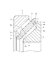
- the tapered roller bearing 1 of the first embodiment includes an outer ring 2 having an outer ring raceway surface 2a on an inner peripheral surface, an inner ring 3 having an inner ring raceway surface 3a on an outer peripheral surface, and an outer ring raceway surface 2a.
- a plurality of tapered rollers 4 that are rotatably arranged between the inner ring raceway surface 3a, and a resin cage 10 that defines a plurality of pockets P that accommodate and hold the plurality of tapered rollers 4 at a predetermined interval;
- the outer ring raceway surface 2a formed on the outer ring 2 is provided on the inner circumferential surface of the outer ring 2 so that the inner diameter gradually increases from the small diameter side toward the large diameter side.
- the inner ring 3 includes a large flange 3b formed to protrude radially outward at an end portion on the large diameter side.
- the inner ring raceway surface 3a continues to the small diameter side end surface 3c, and extends from the small diameter side end surface 3c to the large flange 3b. It is provided so that the outer diameter gradually increases as it goes to.
- the contact angle ⁇ which is the angle formed between the tangent line of the outer ring raceway surface 2a and the rotational axis of the tapered roller bearing 1, is set to 45 °.
- the rigidity is improved.
- the moment stiffness can be improved by setting the contact angle ⁇ in the range of 35 ° to 55 °, and the distance between the bearings is short. Specifically, the distance between the bearings is four times the assembly width T of the bearings. In the following cases, when the contact angle ⁇ is in the range of 35 ° to 55 °, the distance between the operating points can be increased, which is particularly effective in improving the moment rigidity of the bearing.
- the ratio of the radial cross-sectional thickness H to the inner diameter d is set to be 0.05 ⁇ H / d ⁇ 0.15, and the contact angle ⁇ is set to be as large as 45 °. However, it is thin in the radial direction and has a compact configuration.
- the roller length Lw can be increased, and the ratio of the roller length Lw to the inner ring width B is set to 0.8 ⁇ Lw / B ⁇ 1.2.
- the load capacity is increased to improve the moment rigidity, thereby extending the service life.
- the ratio of the roller large diameter Dw1 to the radial cross-sectional thickness H is set to 0.3 ⁇ Dw1 / H ⁇ 0.6.
- the ratio of the inner ring large collar side height (D1-d) / 2 and the radial cross-sectional thickness H is 0.7 ⁇ (D1-d) / 2H ⁇ 0.9.
- the large wall 3b can be backed up, and the strength of the large wall 3b can be greatly improved.
- (D1 ⁇ d) / 2H ⁇ 1 the outer diameter of the large collar is larger than the outer diameter of the outer ring, so that the large collar comes into contact with the housing.
- the height of the ridge needs to be (D1 ⁇ d) / 2 ⁇ H, that is, (D1 ⁇ d) / 2H ⁇ 1.
- T represents the assembly width of the tapered roller bearing
- D represents the outer diameter of the tapered roller bearing.
- the tapered roller bearing 1 applied to the present embodiment is usually one having a bearing inner diameter of 30 to 500 mm and a bearing outer diameter of 33 to 650 mm. Therefore, since the bearing size is smaller than that for the main shaft of the wind power generator, the size of the tapered roller is small and the weight is light. For this reason, for the tapered roller bearing 1, it is preferable to employ an integrated resin cage as in the present invention.
- the resin cage 10 is provided between the large-diameter ring portion 11 and the small-diameter ring portion 12 and the large-diameter ring portion 11 and the small-diameter ring portion 12 that are separated in the axial direction.
- a plurality of pillars 13 connected at a predetermined interval in the circumferential direction are provided.
- the resin cage 10 is manufactured by injection molding, and it is particularly desirable that the resin cage 10 be injection molded by an axial draw mold that is advantageous in terms of cost.
- a thermoplastic resin having a certain level of heat resistance can be used as the base resin used in the resin composition that can be used in the cage 10. Further, in order to satisfy the fatigue resistance required for the cage 10 and a low water absorption dimensional change, a crystalline resin is more preferable.
- PPS Polyphenylene sulfide
- PEEK polyether ether ketone
- modified polyamide 6T such as polyamide 6T / 6I, polyamide MXD6, polyamide 9T, and polyamide 4T can be used.
- polyphenylene sulfide (PPS) resin and polyether ether ketone (PEEK) resin that hardly change in water absorption dimension are particularly suitable.
- this resin composition contains a reinforcing fiber material in order to achieve a certain level of strength and to suppress changes in linear expansion coefficient and water absorption dimension.
- a reinforcing fiber material it is preferable to use a surface treatment product such as glass fiber, carbon fiber, and aramid fiber (adhesion with the base resin is improved by surface treatment with a silane coupling agent / sizing agent). it can.
- the content of the reinforcing fiber material in the resin composition is 10% by weight or more and 40% by weight or less, more preferably 15 to 30% by weight, based on the entire resin composition.
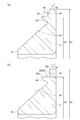
- the cross-sectional shape of the column portion 13 is different between the portion near the large-diameter ring portion and the portion near the small-diameter ring portion, and is switched in the middle of the column portion 13. That is, the portion near the large-diameter ring portion of the column portion 13 shown in FIG. 3A has a protruding portion 14 provided with a conical surface 14 a on the inner diameter side with respect to the pitch circle C of the tapered roller 4. . 3B has a protruding portion 15 having a conical surface 15a provided on the outer diameter side with respect to the pitch circle C of the tapered roller 4. .
- the curvatures of the conical surfaces 14 a and 15 a are set slightly larger than the curvature of the tapered rollers 4.
- the pocket inner diameter side opening width W ⁇ b> 1 is narrower than the roller large diameter Dw ⁇ b> 1.
- the outer diameter side opening width W2 of the pocket is smaller than the small roller diameter Dw2.
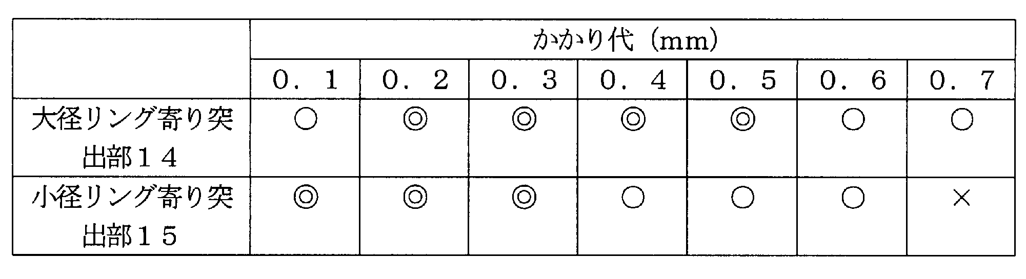
- Table 1 shows the amount of protrusion (Dw1-W1) at the protrusion 14 near the large-diameter ring portion of the column 13 and the amount of protrusion (Dw2-W2) at the protrusion 15 near the small-diameter ring of the column 13
- Dw1-W1 the amount of protrusion
- Dw2-W2 the amount of protrusion
- the amount of protrusion (Dw1-W1) at the protruding portion 14 near the large-diameter ring portion of the column portion 13 is 0.1 mm to 0.7 mm
- the protruding portion 15 near the small-diameter ring portion of the column portion 13 is
- the allowance (Dw2-W2) is preferably 0.1 mm to 0.6 mm.
- the margin (Dw1-W1) at the protruding portion 14 near the large-diameter ring portion of the column portion 13 is set to 0.2 mm to 0.6 mm.
- the allowance (Dw2-W2) at the protrusion 15 near the small-diameter ring portion of the portion 13 is 0.1 mm to 0.3 mm.
- an annular notch is formed on the inner peripheral surface of the large-diameter ring portion 11 so that the wall thickness t 1 of the large-diameter ring portion 11 is thinner than the wall thickness t of the column portion 13.
- 16 is formed, and the inner peripheral surface of the cage 10 is formed in a stepped shape from the column portion 13 to the large-diameter ring portion 11.
- the notch part 16 has notched a part of pillar part 13 along radial direction.
- the thickness of the large-diameter ring portion 11 is reduced, and the protruding portion 14 of the column portion 13 is partially cut away, so that the amount of elastic deformation of the column portion 13 on the large-diameter ring portion side is increased, and the It becomes easy to insert the tapered roller 4 from the inside of 10.
- the large collar 3b of the inner ring 3 can enter the annular notch 16, and the large collar 3b can be increased by that amount to increase the load of the axial load.
- the notch part 16 has notched a part of pillar part 13 along radial direction, it can avoid interference with the large collar 3b.
- the inclination angle ⁇ 2 of the outer peripheral surface of the cage 10 with respect to the rotation axis of the tapered roller bearing 1 corresponds to a contact angle ⁇ of the tapered roller bearing 1 of 32 ° 30 ′ or more and 55 °. Is set to be less than or equal to 32 ° 30 ′ or more and 54 ° or less.
- the tapered roller bearing 1 of the present embodiment is desirably used as a bearing arrangement in a back surface combination (DB combination). Further, the tapered roller bearing 1 can improve the moment rigidity if the preload is increased, but on the other hand, since the life of the bearing may be reduced, a special heat treatment (carburizing treatment or carbonitriding treatment) is performed. It is preferable to use long-life steel subjected to.
- the basic dynamic load rating ratio shown in Table 3 is a value compared with Comparative Example 4 when the basic dynamic load rating of Comparative Example 4 is 1.
- ⁇ indicates that it is feasible and effective
- ⁇ indicates that the performance is inferior to “ ⁇ ”
- ⁇ indicates that the effect is not good.
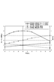
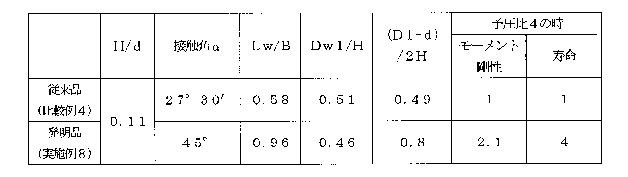
- the moment stiffness ratio and life ratio of each preload ratio of the invention product (Example 8) when the moment stiffness and life of the conventional product (Comparative Example 4) tapered roller bearing with a preload ratio of 4 are set as 1. 4 and FIG.
- the preload ratio is a value expressed as a ratio with respect to “1” when a predetermined value of preload is set to “1”. Also, the preload ratio “0” indicates 0 “N”.
- the inventive tapered roller bearing (Example 8) has a moment rigidity ratio of 2.1 with respect to the conventional product (Comparative Example 4) and a life ratio with respect to Comparative Example 4 when the preload ratio is 4. Is 4. It can also be seen that the tapered roller bearing of the invention (Example 8) shows a higher value than the conventional product (Comparative Example 4) in the moment rigidity ratio and life ratio at any preload ratio.
- the large ring 3b is formed at the large diameter side end portion of the inner ring 3, and the inner ring raceway surface 3a is the small diameter side end surface 3c of the inner ring 3.
- the contact angle ⁇ is set to 45 °.
- the moment rigidity can be improved by setting the contact angle ⁇ in the range of 35 ° to 55 °.
- the distance between the bearings is short, specifically, the distance between the bearings is 4 of the assembly width T of the bearing. If the contact angle ⁇ is in the range of 35 ° to 55 ° in the case of the double or less, it is particularly effective in improving the moment rigidity of the bearing.
- the ratio of the inner ring large collar side height (D1-d) / 2 and the radial cross-sectional thickness H is 0.7 ⁇ (D1- d) Since 2H ⁇ 0.9 is set, it is possible to back up the large pot, and to greatly improve the strength of the large pot 3b.
- the ratio of the roller length Lw to the inner ring width B is set to 0.8 ⁇ Lw / B ⁇ 1.2, the size can be reduced, the load capacity can be increased, the high moment rigidity, Life can be extended.
- the ratio of the radial cross-sectional thickness H to the internal diameter d is set to 0.05 ⁇ H / d ⁇ 0.15, the structure can be made thin and thin in the radial direction.
- the ratio of the tapered roller large diameter Dw1 to the radial cross-sectional thickness H is 0.3 ⁇ Dw1 / H ⁇ 0.6, it is possible to reduce the size and increase the load capacity. High moment rigidity and long life can be achieved.
- An annular notch 16 is formed on the inner peripheral surface of the large diameter ring portion 11 so that the thickness t 1 of the large diameter ring portion 11 is thinner than the thickness t of the column portion 13. Thereby, the amount of elastic deformation of the column portion 13 of the cage 1 is increased, and the tapered roller 4 can be easily inserted from the inside of the cage 10.
- the column portion 13 has a margin of 0.1 mm to 0.7 mm at the protruding portion 14 near the large diameter ring portion, and the inner diameter side opening width W1 of the pocket P is narrower than the large roller diameter Dw1 of the tapered roller 4.
- the outer diameter side opening width W2 of the pocket P is narrower than the small roller diameter Dw2 of the tapered roller 4. Formed.
- the cage 10 of the present invention is not limited to the axial draw type injection molding, that is, the column portion 13 is at least a part of the inner diameter side of the pocket P at 0.1 mm to 0.7 mm.
- the opening width W1 of the inner diameter side of the pocket P is formed to be narrower than the roller large diameter Dw1 of the tapered roller 4, and at least part of the outer diameter side of the pocket P is 0.1 mm to 0.00 mm.
- the allowance of 6 mm is used, and the outer diameter side opening width W ⁇ b> 2 of the pocket P may be formed to be narrower than the roller small diameter Dw ⁇ b> 2 of the tapered roller 4.
- the inclination angle alpha 2 of the retainer 10, 32 ° 30' because it is set to less than 55 °, the retainer 10, the contact angle alpha is 35 ° ⁇ 55 to tapered roller bearing 1 of the steep ° Can be applied.
- the tapered roller bearing 1 of the present embodiment eliminates the inner ring gavel to increase the moment moment and realize a longer roller length in order to achieve high moment rigidity and a long life.
- this embodiment improves the roller holding performance of the holder
- FIG. Therefore, the cage 10 employed in the tapered roller bearing 1 of the present embodiment realizes its role in place of the inner ring gavel that originally functions to hold the tapered roller 4, and has a contact angle of 35. It is possible to effectively suppress the roller drop of the steep tapered roller bearing 1 at a degree of 55 ° to 55 °.
- the annular notch 16 is formed on the inner peripheral surface of the large-diameter ring portion 11, but the present invention can be applied to the inner peripheral surface of the large-diameter ring portion 11 and the small-diameter ring portion 12.
- An annular notch may be formed on at least one of the outer peripheral surface.
- the wall thicknesses t 1 and t 2 of both the ring portions 11 and 12 are columns on both the inner peripheral surface of the large diameter ring portion 11 and the outer peripheral surface of the small diameter ring portion 12.
- the annular notches 16 and 17 may be formed so as to be thinner than the wall thickness t of the portion 13 so that the tapered rollers 4 can be easily inserted from both sides of the cage 10.
- the large collar 3 b of the inner ring 3 includes a large collar surface 3 d in contact with the large end face 4 a of the tapered roller 4 and a maximum outer diameter position (diameter of the large collar surface 3 d.
- a position facing the large-diameter ring portion 11 of the retainer 10, particularly in this embodiment, the notch portion 16 and A concave portion 20 is provided at the opposing position.
- the thickness of the large-diameter ring portion 11 of the cage 10 can be increased to the maximum by providing the recess 20 in the large collar 3b, and thereby the strength of the cage 10 can be improved.
- the lubricant can be held in the recess 20, the lubricity of the large collar surface 3d of the inner ring 3 can be improved.
- the space for retaining the lubricant can be increased by the notch 16 and the recess 20.
- the lubricant grease or lubricating oil can be used, and in the case of lubricating oil, it is relatively easy to be retained in the recess 20 when a lubricating oil having a higher viscosity is employed.
- the concave portion 20 has a generatrix shape formed by a curved surface formed of a single arc having a radius of curvature r.
- the boundary between the large collar outer diameter surface 3e (position indicated by the diameter D1) and the concave portion 20 and the boundary between the maximum outer diameter position (position indicated by the diameter D2) and the concave portion 20 of the large collar surface 3d are chamfering.
- the recess 20 includes a ridge line e (denoted by a point e in the cross-sectional view of FIG. 3) where the recess 20 and the outer diameter surface 3e of the large collar intersect to ensure the strength of the large collar 3b.
- it is formed on the inner side in the axial direction from the virtual plane I perpendicular to the rotation axis.
- the inner ring outer diameter that is, the diameter of the large collar outer diameter surface 3e is D1
- the diameter of the large collar surface 3d at the maximum outer diameter position is D2
- the radius of curvature r of the generatrix of the concave portion 20 formed of a single arc is set such that r ⁇ (D1 ⁇ D2) / 2.
- the recessed part 20 is made into the single circular arc from a viewpoint of the ease of a process, it is not restricted to this, As shown in FIG. 8, several circular arc 21a, 21b which consists of curvature radius r1, r2 is shown. It may be formed by a curved surface formed by or a stepped surface.
- FIG. 9 shows a modified example in which the concave portion 20 is constituted by a step surface 22 and two curved surfaces 24a and 24b made of arcs of curvature radii r3 and r4.
- the step surface 22 has a cylindrical surface 22a near the large collar surface and a large surface. And an annular flat surface 22b extending radially outward from the cylindrical surface 22a near the outer diameter surface.
- the boundary between the large heel outer diameter surface 3e (position indicated by the diameter D1) and the concave portion 20, and the maximum outer diameter position (position indicated by the diameter D2) of the large ridge surface 3d and the concave portion 20 are provided.
- the boundary is chamfered, but the shape of the chamfer is arbitrary, and the boundary between the cylindrical surface 22a and the annular plane 22b may be formed in a curved surface shape. Further, the curvature radii r3 and r4 of the two curved surfaces 24a and 24b may be the same.
- the large collar 3 b is formed at the large diameter side end of the inner ring 3, and the large collar 3 b is the large diameter ring section 11 of the cage 10. Since the concave portion 20 is provided at a position opposite to the inner ring, interference between the large cage 3b and the cage 10 can be avoided, the strength of the cage 10 can be improved, and a lubricant can be retained in the concave portion 20 to 3 can improve the lubricity of the large collar surface 3d.
- the recess 20 is formed between the large collar surface 3d that is in contact with the large end surface 4a of the tapered roller 4 and the large collar outer diameter surface 3e that is larger in diameter than the maximum outer diameter position of the large collar surface 3d. What is necessary is just to be comprised from either the surface or the combination of this curved surface and this level
- the generatrix shape of the concave portion 20 may be formed by a single arc or a plurality of arcs 21a and 21b.
- the shape of the generatrix of the concave section 20 is By setting the curvature radius r to r ⁇ (D1 ⁇ D2) / 2, it is possible to achieve both the retention performance of the lubricant and the strength of the collar.
- the recess 20 is formed on the inner side in the axial direction from the virtual plane I perpendicular to the rotation axis including the ridge line e where the recess 20 and the outer diameter surface 3e intersect, and the strength of the greater collar 3b can be ensured. it can.
- the step surface 22 when the recess 20 is constituted by a step surface 22 and two curved surfaces 24a and 24b, the step surface 22 includes a cylindrical surface 22a near the large collar surface 3d and a large collar outer diameter surface. 3e and an annular flat surface 22b extending radially outward from the cylindrical surface 22a, and can hold more lubricant.
- the cylindrical surface 23 extending along the axial direction is formed, and then the curved surface
- the recessed part 20 formed by may be formed.
- the cylindrical surface 22a connected to the large collar surface 3d and the large collar outer diameter may be formed by a step surface 22 having an annular flat surface 22b connected to the surface 3e. Thereby, more lubricant can be held.
- the inner ring 3 may be constituted by the outermost diameter portion of the recess 20 without constituting the large outer diameter surface 3e by the cylindrical surface.
- the tapered roller bearing of the present invention can be applied to various reduction gears for industrial robots, conveying devices, motors, and the like, and specific application examples are shown below.
- FIG. 11 is a longitudinal sectional view of an orthogonal shaft gear reducer to which the tapered roller bearing of the present invention is applied.
- This orthogonal shaft gear reducer is incorporated into a gear reducer used in logistics equipment in combination with a motor, and is aligned to both the L side (the left side of the reducer as viewed from the input side) and the R side.
- FIG. 11 shows an example of L-axis alignment.
- reference numeral 201 denotes a gear box that houses a reduction gear.
- 202 is a solid output shaft that is L-axis aligned
- 203 is a hollow output shaft.
- the upper half shows the case where the solid output shaft 202 is used, and the lower half shows the case where the hollow output shaft 203 is used.
- the gear box 201 is configured symmetrically with respect to the center line c, and has the same shape and dimensions.
- the left and right output shaft protruding portions fix the output shaft cover 206 or 207 to the gear box 201 by bolting.
- only the output shaft cover 206 on the shaft output side is processed with a shaft alignment hole.
- the solid output shaft 202 is supported on both sides by the tapered roller bearing 1 of the present invention fitted in the gear box 201, and the output gear 204 is fitted on both sides of the intermediate maximum diameter portion 202a.
- the output gear fitting portion 202c to be paired is provided.
- the diameter of the fitting portion 202d of the tapered roller bearing is the same as that of the solid output shaft 202, including the case of the hollow output shaft 203 shown in the lower half of FIG.
- a pinion 212 is provided on a shaft 211 that supports a bevel gear 210 that meshes with a bevel pinion (not shown).
- the output gear 204 meshes with the pinion 212, and the power transmitted to the bevel gear 210 is transmitted to the output shafts 202 and 203.
- FIG. 12 is an enlarged side sectional view of a reduction gear portion of a hypoid type motor with a reduction gear to which the tapered roller bearing of the present invention is applied.
- the speed reducer 301 is attached to the flange surface 302a of the bearing bracket 302 of the electric motor. Further, inside the speed reducer 301, a hypoid gear 304 meshed with a pinion 303 extending from the electric motor, a spindle 305 attached through the center of the hypoid gear 304, and the spindle 305 are rotatably supported.
- Two tapered roller bearings 1 and two-piece casings 307 and 308 provided with storage portions 307a and 308a for storing these tapered roller bearings 1 are configured.
- the tapered roller bearing 1 used in Application Example 1 and Application Example 2 has an outer ring outer diameter of 650 mm or less and an inner ring inner diameter of 500 mm or less.
- the axial load and the radial load acting on the output shafts 202 and 203 and the spindle 305 can be supported while having a compact design.
- moment rigidity can be improved by attaching the tapered roller bearing 1 of this invention with a back surface combination. In order to obtain high moment rigidity, it is more advantageous to use roller bearings than ball bearings.
- tapered roller bearings have an extended line of roller rolling surfaces and an extended line of outer and inner ring raceway surfaces. Since the structure intersects at one place on the shaft, slippage between the roller rolling surface and the outer and inner ring raceway surface hardly occurs, and high reliability can be obtained as compared with the cylindrical roller bearing.
- the present invention includes a Japanese patent application filed on December 25, 2012 (Japanese Patent Application No. 2012-280994), a Japanese patent application filed on April 4, 2013 (Japanese Patent Application No. 2013-078999), and November 21, 2013. This is based on a Japanese patent application (Japanese Patent Application No. 2013-241278) filed in Japan, the contents of which are incorporated herein by reference.
Landscapes
- Engineering & Computer Science (AREA)
- General Engineering & Computer Science (AREA)
- Mechanical Engineering (AREA)
- Rolling Contact Bearings (AREA)
Abstract
Description
更に、最近、変速機用として使用される軸受では、高負荷容量で、かつ、変速機のコンパクト化を対応できるもの、つまり、軸受サイズを変更することなく、従来と同等以上の機能であることが求められる。
また、特許文献1には、保持器へのころの挿入性に関する検討がなかった。さらに、特許文献1に記載の円錐ころ軸受に使用される保持器は、ころと保持器とが一体化されているが、円錐ころを保持するためのかかり代に対する記載がない為、円錐ころを保持する性能が十分であるか不明である。更に、この円錐ころ軸受では接触角が35°未満であり、仮に、接触角を35°以上に設定すると、内輪には小鍔がない為、保持器だけでころを十分に保持できないことが懸念される。
(1) 外周面に内輪軌道面を有する内輪と、内周面に外輪軌道面を有する外輪と、前記内輪軌道面と前記外輪軌道面との間に転動自在に配置される複数の円錐ころと、を備える円錐ころ軸受であって、
前記内輪の大径側端部には大鍔が形成され、且つ、前記内輪軌道面は、前記内輪の小径側端面まで連続しており、
接触角αが45°であることを特徴とする円錐ころ軸受。
(2) 内周面に外輪軌道面を有する外輪と、外周面に内輪軌道面を有する内輪と、前記外輪軌道面と前記内輪軌道面との間に転動自在に配置される複数の円錐ころと、を備える円錐ころ軸受であって、
前記内輪の大径側端部には大鍔が形成され、且つ、前記内輪軌道面は、前記内輪の小径側端面まで連続しており、
接触角αが35°~55°であることを特徴とする円錐ころ軸受。
(3) 前記円錐ころ軸受の内径をd、内輪外径をD1としたとき、内輪大鍔側高さ(D1-d)/2と径方向断面肉厚Hの比が0.7<(D1-d)/2H<0.9であることを特徴とする(1)又は(2)に記載の円錐ころ軸受。
(4) ころ長さLwと内輪幅Bの比が0.8<Lw/B<1.2であることを特徴とする(1)~(3)のいずれかに記載の円錐ころ軸受。
(5) 径方向断面肉厚Hと内径dの比が0.05<H/d<0.15であることを特徴とする(1)~(4)のいずれかに記載の円錐ころ軸受。
(6) 前記円錐ころのころ大径Dw1と径方向断面肉厚Hの比が0.3<Dw1/H<0.6であることを特徴とする(1)~(5)のいずれかに記載の円錐ころ軸受。
(7) 軸方向に離間した大径リング部及び小径リング部と、該大径リング部及び小径リング部との間を繋ぐ複数の柱部と、を有し、前記複数の円錐ころを収容保持する複数のポケットを画成する樹脂製保持器をさらに備え、
前記大径リング部の内周面と、前記小径リング部の外周面との少なくとも一方には、該リング部の肉厚が前記柱部の肉厚よりも薄くなるように環状の切欠き部が形成されることを特徴とする(1)~(6)のいずれかに記載の円錐ころ軸受。
(8) 前記環状の切欠き部は、前記大径リング部の内周面に形成され、
前記環状の切欠き部には、前記大鍔が入り込んでいることを特徴とする(7)に記載の円錐ころ軸受。
(9) 軸方向に離間した大径リング部及び小径リング部と、該大径リング部及び小径リング部との間を繋ぐ複数の柱部と、を有し、前記複数の円錐ころを収容保持する複数のポケットを画成する樹脂製保持器をさらに備え、
前記柱部は、前記ポケットの内径側の少なくとも一部において、0.1mm~0.7mmのかかり代とし、前記ポケットの内径側開口幅が前記円錐ころのころ大径より狭くなるように形成され、且つ、
前記ポケットの外径側の少なくとも一部において、0.1mm~0.6mmのかかり代とし、前記ポケットの外径側開口幅が前記円錐ころのころ小径より狭くなるように形成されることを特徴とする(1)~(8)のいずれかに記載の円錐ころ軸受。
(10) 軸方向に離間した大径リング部及び小径リング部と、該大径リング部及び小径リング部との間を繋ぐ複数の柱部と、を有し、前記複数の円錐ころを収容保持する複数のポケットを画成する樹脂製保持器をさらに備え、
前記保持器の傾斜角度は、32°30´以上55°未満に設定されることを特徴とする(1)~(6)のいずれかに記載の円錐ころ軸受。
(11) 前記保持器の傾斜角度は、32°30´以上55°未満に設定されることを特徴とする(7)~(9)のいずれかに記載の円錐ころ軸受。
(12) 前記大鍔は、前記保持器と対向する位置に凹部を有することを特徴とする(1)~(11)のいずれかに記載の円錐ころ軸受。
(13) 前記凹部は、前記円錐ころの大端面に接する大鍔面と、該大鍔面の最大外径位置より大径の大鍔外径面との間に形成され、曲面若しくは段差面、又は該曲面と該段差面との組み合わせのいずれかからなることを特徴とする(12)に記載の円錐ころ軸受。
(14) 前記凹部の母線形状は、単一円弧、又は複数の円弧によって形成されることを特徴とする(13)に記載の円錐ころ軸受。
(15) 前記凹部は、前記凹部と前記大鍔外径面とが交わる稜線を含んで前記円錐ころ軸受の回転軸線に垂直な仮想面よりも軸方向内側に形成されることを特徴とする(14)に記載の円錐ころ軸受。
(16) 前記大鍔外径面の直径をD1、前記大鍔面の最大外径位置での直径をD2としたとき、
前記凹部の母線形状は、曲率半径rが、r≧(D1-D2)/2である単一円弧によって形成されることを特徴とする(14)又は(15)に記載の円錐ころ軸受。
(17) 前記段差面は、前記大鍔面寄りの円筒面と、前記大鍔外径面寄りで、前記円筒面から径方向外側に延びる環状平面と、を有することを特徴とする(13)に記載の円錐ころ軸受。
(18) 内周面に外輪軌道面を有する外輪と、外周面に内輪軌道面を有する内輪と、前記外輪軌道面と前記内輪軌道面との間に転動自在に配置される複数の円錐ころと、前記複数の円錐ころを収容保持する複数のポケットを画成する樹脂製保持器と、を有する円錐ころ軸受であって、
前記保持器は、軸方向に離間した大径リング部及び小径リング部と、該大径リング部及び小径リング部との間を繋ぐ複数の柱部と、を有し、
前記大径リング部の内周面と、前記小径リング部の外周面との少なくとも一方には、該リング部の肉厚が前記柱部の肉厚よりも薄くなるように環状の切欠き部が形成されることを特徴とする円錐ころ軸受。
(19) 前記大径リング部の内周面には、該大径リング部の肉厚が前記柱部の肉厚よりも薄くなるように環状の切欠き部が形成され、
前記内輪の大径側端部には大鍔が形成され、且つ、前記内輪軌道面は、前記内輪の小径側端面まで連続しており、
前記環状の切欠き部には、前記大鍔が入り込んでいることを特徴とする(18)記載の円錐ころ軸受。
(20) 前記柱部は、前記ポケットの内径側の少なくとも一部において、0.1mm~0.7mmのかかり代とし、前記ポケットの内径側開口幅が前記円錐ころのころ大径より狭くなるように形成され、且つ、
前記ポケットの外径側の少なくとも一部において、0.1mm~0.6mmのかかり代とし、前記ポケットの外径側開口幅が前記円錐ころのころ小径より狭くなるように形成されることを特徴とする(18)又は(19)記載の円錐ころ軸受。
(21) 前記内輪の大径側端部には大鍔が形成され、且つ、前記内輪軌道面は、前記内輪の小径側端面まで連続しており、
接触角αが35°~55°であることを特徴とする(18)~(20)のいずれかに記載の円錐ころ軸受。
(22) 接触角αが45°であることを特徴とする(21)に記載の円錐ころ軸受。
(23) 前記保持器の傾斜角度は、32°30´以上55°未満に設定されることを特徴とする(18)~(22)のいずれかに記載の円錐ころ軸受。
なお、接触角αは、35°~55°の範囲とすることでモーメント剛性を向上することができ、軸受間距離が短い、具体的には、軸受間距離が軸受の組立幅Tの4倍以下の場合に、接触角αを35°~55°の範囲とすると、作用点間距離を長くすることができ、軸受のモーメント剛性を向上する上で特に有効である。
図1に示すように、第1実施形態の円錐ころ軸受1は、内周面に外輪軌道面2aを有する外輪2と、外周面に内輪軌道面3aを有する内輪3と、外輪軌道面2aと内輪軌道面3aとの間に転動自在に配置される複数の円錐ころ4と、複数の円錐ころ4を所定の間隔で収容保持する複数のポケットPを画成する樹脂製保持器10と、を有する。
なお、接触角αは、35°~55°の範囲とすることでモーメント剛性を向上することができ、軸受間距離が短い、具体的には、軸受間距離が軸受の組立幅Tの4倍以下の場合に、接触角αを35°~55°の範囲とすると、作用点間距離を長くすることができ、軸受のモーメント剛性を向上する上で特に有効である。
ここで、(D1-d)/2H≧1とすると、外輪外径より大鍔外径のほうが大きくなるため、大鍔がハウジングと接触してしまう。このため、ハウジングとの干渉を考慮すると、大鍔の高さは、(D1-d)/2<H、即ち、(D1-d)/2H<1とする必要がある。そして、軸受の傾き、変形、動き量等の余裕分を考慮すると、(D1-d)/2H<0.9とすることが好ましい。また、(D1-d)/2H≦0.7とすると、大鍔の強度が足りなくなる可能性があるため、(D1-d)/2H>0.7とすることが好ましい。
なお、図1中、Tは円錐ころ軸受の組立幅、Dは円錐ころ軸受の外径を表わしている。また、本実施形態に適用される円錐ころ軸受1としては、通常、軸受内径が30~500mm、軸受外径が33~650mmのものである。したがって、軸受サイズが風力発電機主軸用のものに比べて小さいため、円錐ころのサイズも小さく、重量も軽い。このため、円錐ころ軸受1には、本発明のような一体型樹脂製の保持器を採用することが好適である。
また、保持器10として要求される耐疲労性と、低い吸水寸法変化を満足するために、結晶性樹脂の方が好適であり、具体的には、ポリアミド46、ポリアミド66、芳香族ポリアミド樹脂、ポリフェニレンサルファイド(PPS)樹脂、ポリエーテルエーテルケトン(PEEK)樹脂等である。芳香族ポリアミド樹脂としては、ポリアミド6T/6I等の変性ポリアミド6T,ポリアミドMXD6,ポリアミド9T,ポリアミド4Tを使用することができる。以上説明したベース樹脂の中で、吸水寸法変化がほとんど無いポリフェニレンサルファイド(PPS)樹脂、ポリエーテルエーテルケトン(PEEK)樹脂が特に好適である。
樹脂組成物中の強化繊維材の含有量は、樹脂組成物全体の10重量%以上40重量%以下、より好ましくは15~30重量%である。
なお、円錐面14a、15aの曲率は、円錐ころ4の曲率よりも若干大きく設定されている。
また、環状の切欠き部16には、内輪3の大鍔3bが入り込むことができ、その分だけ大鍔3bを大きくしてアキシャル荷重の負荷を増大することができる。さらに、切欠き部16は、柱部13の一部を径方向に沿って切欠いているので、大鍔3bとの干渉を回避することができる。
また、円錐ころ軸受1は、予圧荷重を高めればモーメント剛性を向上する事が可能であるが、その反面、軸受の寿命が低下する可能性があるため、特殊熱処理(浸炭処理又は浸炭窒化処理)を施した長寿命鋼を使用することが好ましい。
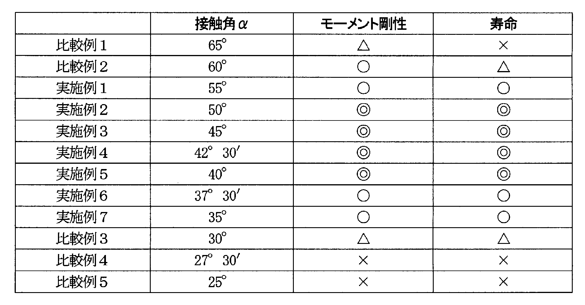
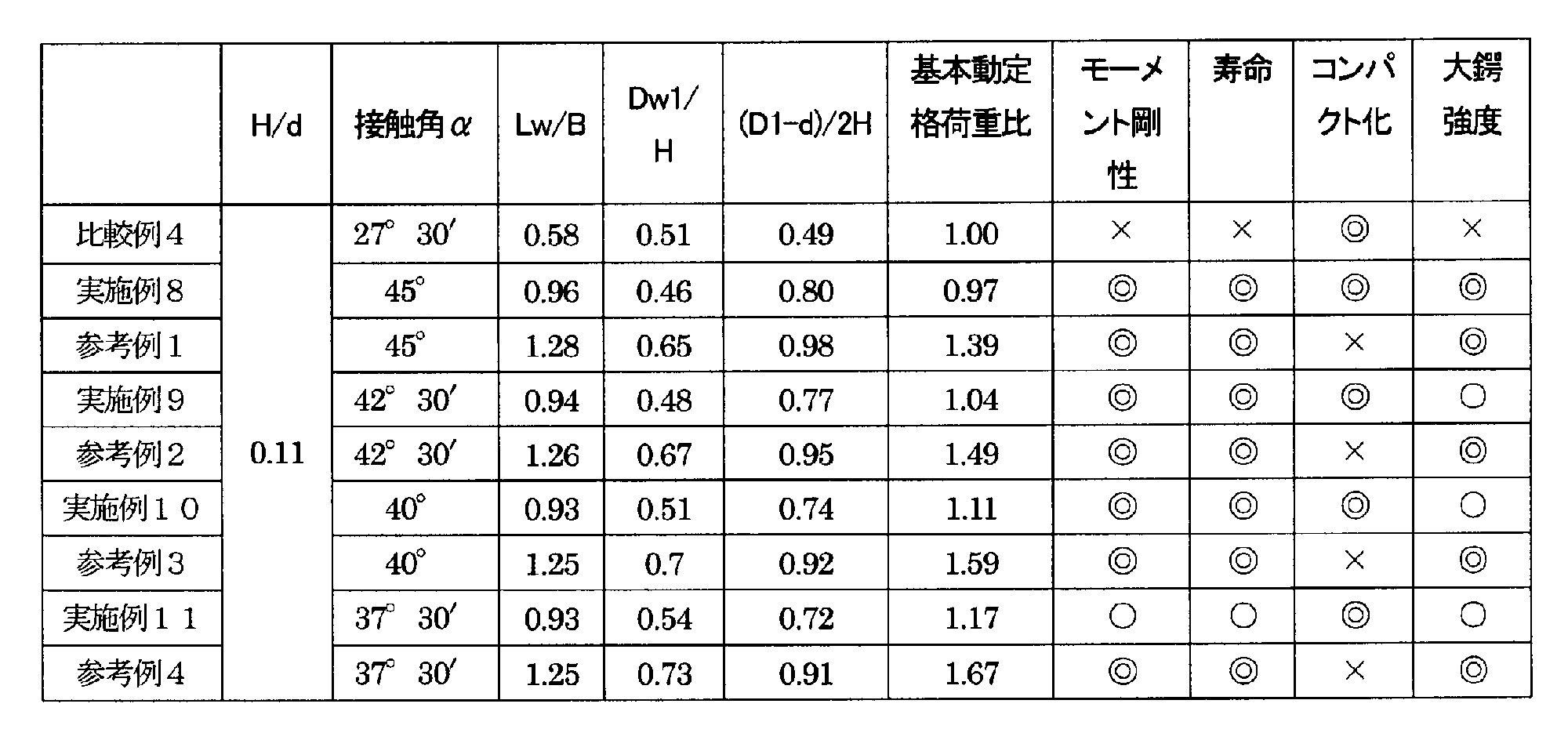
また、接触角αは、35°~55°の範囲とすることでモーメント剛性を向上することができ、軸受間距離が短い場合、具体的には、軸受間距離が軸受の組立幅Tの4倍以下の場合に、接触角αを35°~55°の範囲とすると、軸受のモーメント剛性を向上する上で特に有効である。
なお、本発明の保持器10は、アキシャルドロー型での射出成形に限定されるものでなく、即ち、柱部13は、ポケットPの内径側の少なくとも一部において、0.1mm~0.7mmのかかり代とし、ポケットPの内径側開口幅W1が円錐ころ4のころ大径Dw1より狭くなるように形成され、且つ、ポケットPの外径側の少なくとも一部において、0.1mm~0.6mmのかかり代とし、ポケットPの外径側開口幅W2が円錐ころ4のころ小径Dw2より狭くなるように形成されればよい。
次に、本発明の第2実施形態に係る円錐ころ軸受について、図面に基づき詳細に説明する。なお、第1実施形態のものと同一又は同等部分については、同一符号を付して、説明を省略或いは簡略化する。
図11は、本発明の円錐ころ軸受が適用される直交軸歯車減速機の縦断面図である。この直交軸歯車減速機は、モータと組合せて物流機器等に用いる歯車減速機に組み込まれ、L側(入力側より見て減速機左側面)と、R側の両方に軸出しをするものであり、図11は、L軸出しの例である。
図12は、本発明の円錐ころ軸受が適用されるハイポイド式の減速機付き電動機の減速機部の拡大側断面図である。
いずれの適用例においても、本発明の円錐ころ軸受1を使用することで、コンパクトな設計でありながら、出力軸202,203、及びスピンドル305に作用するアキシャル荷重及びラジアル荷重を支承することができる。
また、図11及び図12に示すように、本発明の円錐ころ軸受1を背面組合せで取り付けることにより、モーメント剛性を向上することができる。
また、高モーメント剛性を得るためには、玉軸受よりもころ軸受を適用する方が有利であり、特に円錐ころ軸受は、ころ転動面の延長線と外内輪軌道面の延長線が、回転軸上の1ヶ所で交わる構造であるため、ころ転動面と外内輪軌道面間の滑りが発生し難く、円筒ころ軸受に比べて高い信頼性を得ることができる。
2 外輪
2a 外輪軌道面
3 内輪
3a 内輪軌道面
3b 大鍔
3d 大鍔面
3e 大鍔外径面
4 円錐ころ
4a 大端面
10 円錐ころ軸受用樹脂製保持器
11 大径リング部
12 小径リング部
13 柱部
14、15 突出部
14a、15a 円錐面
20 凹部
22 段差面
B 内輪幅
C 円錐ころのピッチ円
D 外径
D1 内輪外径(大鍔外径面の直径)
D2 大鍔面の最大外径位置での直径
Dw1 ころ大径
H 径方向断面肉厚
Lw ころ長さ
P ポケット
T 組立幅
d 内径
e 稜線
r 曲率半径
α 接触角
α2 保持器傾斜角度
Claims (23)
- 内周面に外輪軌道面を有する外輪と、外周面に内輪軌道面を有する内輪と、前記外輪軌道面と前記内輪軌道面との間に転動自在に配置される複数の円錐ころと、を備える円錐ころ軸受であって、
前記内輪の大径側端部には大鍔が形成され、且つ、前記内輪軌道面は、前記内輪の小径側端面まで連続しており、
接触角αが45°であることを特徴とする円錐ころ軸受。 - 内周面に外輪軌道面を有する外輪と、外周面に内輪軌道面を有する内輪と、前記外輪軌道面と前記内輪軌道面との間に転動自在に配置される複数の円錐ころと、を備える円錐ころ軸受であって、
前記内輪の大径側端部には大鍔が形成され、且つ、前記内輪軌道面は、前記内輪の小径側端面まで連続しており、
接触角αが35°~55°であることを特徴とする円錐ころ軸受。 - 前記円錐ころ軸受の内径をd、内輪外径をD1としたとき、内輪大鍔側高さ(D1-d)/2と径方向断面肉厚Hの比が0.7<(D1-d)/2H<0.9であることを特徴とする請求項1又は2に記載の円錐ころ軸受。
- ころ長さLwと内輪幅Bの比が0.8<Lw/B<1.2であることを特徴とする請求項1~3のいずれか1項に記載の円錐ころ軸受。
- 径方向断面肉厚Hと内径dの比が0.05<H/d<0.15であることを特徴とする請求項1~4のいずれか1項に記載の円錐ころ軸受。
- 前記円錐ころのころ大径Dw1と径方向断面肉厚Hの比が0.3<Dw1/H<0.6であることを特徴とする請求項1~5のいずれか1項に記載の円錐ころ軸受。
- 軸方向に離間した大径リング部及び小径リング部と、該大径リング部及び小径リング部との間を繋ぐ複数の柱部と、を有し、前記複数の円錐ころを収容保持する複数のポケットを画成する樹脂製保持器をさらに備え、
前記大径リング部の内周面と、前記小径リング部の外周面との少なくとも一方には、該リング部の肉厚が前記柱部の肉厚よりも薄くなるように環状の切欠き部が形成されることを特徴とする請求項1~6のいずれか1項に記載の円錐ころ軸受。 - 前記環状の切欠き部は、前記大径リング部の内周面に形成され、
前記環状の切欠き部には、前記大鍔が入り込んでいることを特徴とする請求項7に記載の円錐ころ軸受。 - 軸方向に離間した大径リング部及び小径リング部と、該大径リング部及び小径リング部との間を繋ぐ複数の柱部と、を有し、前記複数の円錐ころを収容保持する複数のポケットを画成する樹脂製保持器をさらに備え、
前記柱部は、前記ポケットの内径側の少なくとも一部において、0.1mm~0.7mmのかかり代とし、前記ポケットの内径側開口幅が前記円錐ころのころ大径より狭くなるように形成され、且つ、
前記ポケットの外径側の少なくとも一部において、0.1mm~0.6mmのかかり代とし、前記ポケットの外径側開口幅が前記円錐ころのころ小径より狭くなるように形成されることを特徴とする請求項1~8のいずれか1項に記載の円錐ころ軸受。 - 軸方向に離間した大径リング部及び小径リング部と、該大径リング部及び小径リング部との間を繋ぐ複数の柱部と、を有し、前記複数の円錐ころを収容保持する複数のポケットを画成する樹脂製保持器をさらに備え、
前記保持器の傾斜角度は、32°30´以上55°未満に設定されることを特徴とする請求項1~6のいずれか1項に記載の円錐ころ軸受。 - 前記保持器の傾斜角度は、32°30´以上55°未満に設定されることを特徴とする請求項7~9のいずれか1項に記載の円錐ころ軸受。
- 前記大鍔は、前記保持器と対向する位置に凹部を有することを特徴とする請求項1~11のいずれか1項に記載の円錐ころ軸受。
- 前記凹部は、前記円錐ころの大端面に接する大鍔面と、該大鍔面の最大外径位置より大径の大鍔外径面との間に形成され、曲面若しくは段差面、又は該曲面と該段差面との組み合わせのいずれかからなることを特徴とする請求項12に記載の円錐ころ軸受。
- 前記凹部の母線形状は、単一円弧、又は複数の円弧によって形成されることを特徴とする請求項13に記載の円錐ころ軸受。
- 前記凹部は、前記凹部と前記大鍔外径面とが交わる稜線を含んで前記円錐ころ軸受の回転軸線に垂直な仮想面よりも軸方向内側に形成されることを特徴とする請求項14に記載の円錐ころ軸受。
- 前記大鍔外径面の直径をD1、前記大鍔面の最大外径位置での直径をD2としたとき、
前記凹部の母線形状は、曲率半径rが、r≧(D1-D2)/2である単一円弧によって形成されることを特徴とする請求項14又は15に記載の円錐ころ軸受。 - 前記段差面は、前記大鍔面寄りの円筒面と、前記大鍔外径面寄りで、前記円筒面から径方向外側に延びる環状平面と、を有することを特徴とする請求項13に記載の円錐ころ軸受。
- 内周面に外輪軌道面を有する外輪と、外周面に内輪軌道面を有する内輪と、前記外輪軌道面と前記内輪軌道面との間に転動自在に配置される複数の円錐ころと、前記複数の円錐ころを収容保持する複数のポケットを画成する樹脂製保持器と、を有する円錐ころ軸受であって、
前記保持器は、軸方向に離間した大径リング部及び小径リング部と、該大径リング部及び小径リング部との間を繋ぐ複数の柱部と、を有し、
前記大径リング部の内周面と、前記小径リング部の外周面との少なくとも一方には、該リング部の肉厚が前記柱部の肉厚よりも薄くなるように環状の切欠き部が形成されることを特徴とする円錐ころ軸受。 - 前記大径リング部の内周面には、該大径リング部の肉厚が前記柱部の肉厚よりも薄くなるように環状の切欠き部が形成され、
前記内輪の大径側端部には大鍔が形成され、且つ、前記内輪軌道面は、前記内輪の小径側端面まで連続しており、
前記環状の切欠き部には、前記大鍔が入り込んでいることを特徴とする請求項18記載の円錐ころ軸受。 - 前記柱部は、前記ポケットの内径側の少なくとも一部において、0.1mm~0.7mmのかかり代とし、前記ポケットの内径側開口幅が前記円錐ころのころ大径より狭くなるように形成され、且つ、
前記ポケットの外径側の少なくとも一部において、0.1mm~0.6mmのかかり代とし、前記ポケットの外径側開口幅が前記円錐ころのころ小径より狭くなるように形成されることを特徴とする請求項18又は19記載の円錐ころ軸受。 - 前記内輪の大径側端部には大鍔が形成され、且つ、前記内輪軌道面は、前記内輪の小径側端面まで連続しており、
接触角αが35°~55°であることを特徴とする請求項17~請求項20のいずれか1項に記載の円錐ころ軸受。 - 接触角αが45°であることを特徴とする請求項21に記載の円錐ころ軸受。
- 前記保持器の傾斜角度は、32°30´以上55°未満に設定されることを特徴とする請求項18~22のいずれか1項に記載の円錐ころ軸受。
Priority Applications (8)
| Application Number | Priority Date | Filing Date | Title |
|---|---|---|---|
| EP22173734.9A EP4063677B1 (en) | 2012-12-25 | 2013-12-25 | Tapered roller bearing |
| EP20158792.0A EP3690266B1 (en) | 2012-12-25 | 2013-12-25 | Tapered roller bearing |
| EP13868365.1A EP2940323B1 (en) | 2012-12-25 | 2013-12-25 | Tapered roller bearing |
| KR1020157016572A KR101676981B1 (ko) | 2012-12-25 | 2013-12-25 | 원추 롤러 베어링 |
| CN201380059649.4A CN104956102A (zh) | 2012-12-25 | 2013-12-25 | 圆锥滚子轴承 |
| EP18181696.8A EP3404274B1 (en) | 2012-12-25 | 2013-12-25 | Tapered roller bearing |
| US15/446,245 US20170204906A1 (en) | 2012-12-25 | 2017-03-01 | Tapered roller bearing |
| US15/692,028 US10302131B2 (en) | 2012-12-25 | 2017-08-31 | Tapered roller bearing |
Applications Claiming Priority (6)
| Application Number | Priority Date | Filing Date | Title |
|---|---|---|---|
| JP2012-280994 | 2012-12-25 | ||
| JP2012280994 | 2012-12-25 | ||
| JP2013-078999 | 2013-04-04 | ||
| JP2013078999 | 2013-04-04 | ||
| JP2013241278 | 2013-11-21 | ||
| JP2013-241278 | 2013-11-21 |
Related Child Applications (2)
| Application Number | Title | Priority Date | Filing Date |
|---|---|---|---|
| US14/652,267 A-371-Of-International US20150323008A1 (en) | 2012-12-25 | 2012-12-25 | Tapered roller bearing |
| US15/446,245 Continuation US20170204906A1 (en) | 2012-12-25 | 2017-03-01 | Tapered roller bearing |
Publications (1)
| Publication Number | Publication Date |
|---|---|
| WO2014104132A1 true WO2014104132A1 (ja) | 2014-07-03 |
Family
ID=51021209
Family Applications (1)
| Application Number | Title | Priority Date | Filing Date |
|---|---|---|---|
| PCT/JP2013/084751 Ceased WO2014104132A1 (ja) | 2012-12-25 | 2013-12-25 | 円錐ころ軸受 |
Country Status (5)
| Country | Link |
|---|---|
| US (2) | US20170204906A1 (ja) |
| EP (4) | EP3404274B1 (ja) |
| KR (1) | KR101676981B1 (ja) |
| CN (2) | CN107575469B (ja) |
| WO (1) | WO2014104132A1 (ja) |
Cited By (5)
| Publication number | Priority date | Publication date | Assignee | Title |
|---|---|---|---|---|
| USD771166S1 (en) | 2014-06-19 | 2016-11-08 | Nsk Ltd. | Tapered roller bearing cage |
| WO2019189520A1 (ja) | 2018-03-28 | 2019-10-03 | Ntn株式会社 | 円すいころ軸受 |
| US20190360530A1 (en) * | 2015-09-18 | 2019-11-28 | Nsk Ltd. | Tapered roller bearing and manufacturing method for tapered roller bearing |
| CN116292637A (zh) * | 2023-03-08 | 2023-06-23 | 瓦房店轴承集团有限责任公司 | 圆锥轴承车制保持架及其轴承装配方法 |
| US20230323914A1 (en) * | 2022-04-06 | 2023-10-12 | Aktiebolaget Skf | Tapered roller bearing and differential gear with a tapered roller bearing |
Families Citing this family (11)
| Publication number | Priority date | Publication date | Assignee | Title |
|---|---|---|---|---|
| CN108884867B (zh) | 2016-03-24 | 2020-12-18 | Ntn株式会社 | 双排自调心滚子轴承 |
| JP6728907B2 (ja) * | 2016-04-06 | 2020-07-22 | 株式会社ジェイテクト | 転がり軸受 |
| CN107975498B (zh) * | 2016-10-24 | 2021-08-31 | 开利公司 | 用于离心压缩机的扩压器及具有其的离心压缩机 |
| CN107806472A (zh) * | 2017-12-18 | 2018-03-16 | 西北轴承有限公司 | 一种地铁轴箱轴承 |
| DK3783237T3 (da) | 2018-04-20 | 2024-01-08 | Ntn Toyo Bearing Co Ltd | Dobbeltrækket, selvjusterende rulleleje |
| US11460071B2 (en) | 2018-12-07 | 2022-10-04 | Ntn Corporation | Tapered roller bearing |
| JP6778310B2 (ja) * | 2018-12-07 | 2020-10-28 | Ntn株式会社 | 円すいころ軸受 |
| CN111156254B (zh) * | 2020-02-24 | 2024-06-21 | 大连国威轴承股份有限公司 | 一种圆柱滚子轴承焊接支柱保持架 |
| JP7495816B2 (ja) * | 2020-06-03 | 2024-06-05 | Ntn株式会社 | 円すいころ軸受 |
| DE102020116869A1 (de) | 2020-06-26 | 2021-12-30 | Schaeffler Technologies AG & Co. KG | Getriebewellenanordnung mit mindestens einem an einer Welle drehgelagerten Losrad |
| CN113530979B (zh) * | 2021-08-06 | 2022-11-04 | 中车大连机车研究所有限公司 | 一种城市轨道交通齿轮箱用圆锥滚子轴承 |
Citations (6)
| Publication number | Priority date | Publication date | Assignee | Title |
|---|---|---|---|---|
| JPS58165324U (ja) * | 1982-04-30 | 1983-11-04 | 光洋精工株式会社 | 円すいころ軸受 |
| JP2007024110A (ja) * | 2005-07-13 | 2007-02-01 | Ntn Corp | 円錐ころ軸受および円錐ころ軸受の保持器 |
| JP2007032679A (ja) | 2005-07-26 | 2007-02-08 | Ntn Corp | 円すいころ軸受 |
| JP2008180246A (ja) * | 2007-01-23 | 2008-08-07 | Ntn Corp | 円すいころ軸受 |
| JP2010025155A (ja) * | 2008-07-15 | 2010-02-04 | Nsk Ltd | 車輪用円すいころ軸受 |
| JP2012241873A (ja) * | 2011-05-24 | 2012-12-10 | Jtekt Corp | 円すいころ軸受 |
Family Cites Families (71)
| Publication number | Priority date | Publication date | Assignee | Title |
|---|---|---|---|---|
| US1784914A (en) * | 1928-12-26 | 1930-12-16 | Bower Roller Bearing Co | Roller bearing |
| US2059181A (en) | 1935-07-01 | 1936-10-27 | Timken Roller Bearing Co | Self contained taper roller bearing |
| US3477773A (en) | 1968-01-23 | 1969-11-11 | John A Altson | Molded cage for nonseparable assembly of roller bearings |
| US3578828A (en) | 1969-02-18 | 1971-05-18 | Kaman Aerospace Corp | Split-race bearing construction |
| US3733111A (en) | 1971-06-29 | 1973-05-15 | Trw Inc | Tapered roller bearing assembly with antifriction molded cage |
| US4065191A (en) * | 1976-05-13 | 1977-12-27 | Skf Industries, Inc. | Roller skew control for tapered roller bearings |
| IT1085592B (it) | 1976-08-18 | 1985-05-28 | Skf Kugellagerfabriken Gmbh | Gabbiain materiale sintetico per cuscinetti a rulli cilindrici |
| JPS56101417A (en) | 1980-01-10 | 1981-08-14 | Nippon Seiko Kk | Ball bearing |
| US4317601A (en) | 1980-03-31 | 1982-03-02 | The Timken Company | Polymer cage for a tapered roller bearing |
| FR2521665A1 (fr) | 1982-02-18 | 1983-08-19 | Nadella | Cage pour roulement conique a aiguilles ou a rouleaux |
| US4425011A (en) | 1982-06-07 | 1984-01-10 | The Timken Company | Polymer cage for a high speed tapered roller bearing |
| SE432977B (sv) | 1982-06-09 | 1984-04-30 | Skf Ab | Rullager med gjuten plasthallare |
| JPS5950224A (ja) * | 1982-09-16 | 1984-03-23 | Koyo Seiko Co Ltd | 円すいころ軸受用合成樹脂製保持器 |
| US4523862A (en) | 1983-06-07 | 1985-06-18 | Koyo Seiko Company Limited | Tapered roller bearing |
| JPS607423U (ja) | 1983-06-28 | 1985-01-19 | 光洋精工株式会社 | 円すいころ軸受 |
| JPS6196216A (ja) | 1984-10-15 | 1986-05-14 | Nippon Seiko Kk | スラスト自動調心ころ軸受用合成樹脂保持器 |
| JPH0175621U (ja) | 1987-11-10 | 1989-05-23 | ||
| DE3841629C2 (de) * | 1988-12-10 | 1996-07-11 | Skf Gmbh | Rollenlagerung |
| US5096075A (en) | 1989-05-17 | 1992-03-17 | Mcconway & Torley Corporation | Slackless drawbar with gravity responsive wedge |
| JPH0389219U (ja) | 1989-12-27 | 1991-09-11 | ||
| US5267840A (en) | 1991-09-03 | 1993-12-07 | Deco-Grand, Inc. | Power steering pump with balanced porting |
| JP2553847Y2 (ja) | 1992-09-30 | 1997-11-12 | 三菱自動車工業株式会社 | 円錐ころ軸受装置 |
| JPH06300042A (ja) | 1993-04-13 | 1994-10-25 | Nippon Seiko Kk | 静圧気体軸受 |
| JP2600816Y2 (ja) | 1993-07-09 | 1999-10-25 | 日本精工株式会社 | ころ軸受 |
| JP3473187B2 (ja) | 1995-06-20 | 2003-12-02 | 日産自動車株式会社 | トロイダル型無段変速機 |
| JP3699249B2 (ja) | 1997-07-28 | 2005-09-28 | Ntn株式会社 | ハブユニット軸受およびその製造方法 |
| US6146045A (en) | 1998-03-02 | 2000-11-14 | Dana Corporation | Triple seat non-articulating idler arm socket |
| EP1473474B2 (en) | 1998-08-18 | 2009-08-12 | Nsk Ltd | A hub unit for an automobile |
| JP2000130443A (ja) | 1998-10-26 | 2000-05-12 | Ntn Corp | 円すいころ軸受および円すいころ軸受用保持器 |
| JP4465895B2 (ja) | 2000-05-22 | 2010-05-26 | 日本精工株式会社 | ころ軸受 |
| JP4029574B2 (ja) | 2001-01-26 | 2008-01-09 | 株式会社ジェイテクト | 円錐ころ軸受 |
| TWI285243B (en) * | 2002-03-20 | 2007-08-11 | Ntn Toyo Bearing Co Ltd | Cylindrical roller bearing |
| DE10246825B4 (de) | 2002-10-08 | 2019-02-14 | Aktiebolaget Skf | Käfig für ein Wälzlager |
| DE10256855A1 (de) | 2002-12-05 | 2004-06-17 | Ab Skf | Verfahren zur Montage eines zweireihigen Kegelrollenlagers |
| DE20314660U1 (de) | 2003-09-23 | 2003-12-04 | Ab Skf | Lagerung für den Rotor einer Windkraftanlage |
| DE102004046789B4 (de) | 2003-09-30 | 2014-10-09 | Ntn Corp. | Zylinderrollenlager |
| US20070269157A1 (en) | 2004-08-11 | 2007-11-22 | Fahrni Glenn R | Bearing Assemblies for the Pinion Shaft of an Axle Differential |
| JP2007040520A (ja) | 2005-07-01 | 2007-02-15 | Nsk Ltd | 円錐ころ軸受 |
| EP1757823B2 (en) | 2005-08-25 | 2015-01-07 | NTN Corporation | Tapered roller bearing |
| JP4754431B2 (ja) | 2005-08-25 | 2011-08-24 | Ntn株式会社 | 円すいころ軸受 |
| DE102005061102A1 (de) | 2005-12-21 | 2007-07-05 | Schaeffler Kg | Wälzlager |
| DK1998059T3 (da) | 2005-12-21 | 2014-09-22 | Ntn Toyo Bearing Co Ltd | Rulleleje, holdedelssegment og understøtningstruktur til en hovedaksel i en vinddrevet generator |
| JP2007255569A (ja) | 2006-03-23 | 2007-10-04 | Ntn Corp | 円錐ころ軸受、間座および風力発電機の主軸支持構造 |
| JP4697006B2 (ja) | 2006-03-30 | 2011-06-08 | 株式会社ジェイテクト | ころ軸受用保持器及び円錐ころ軸受 |
| WO2008007474A1 (en) | 2006-07-11 | 2008-01-17 | Ntn Corporation | Bearing device for wheel |
| JP2008163999A (ja) * | 2006-12-27 | 2008-07-17 | Ntn Corp | 円錐ころ軸受、円錐ころ軸受の組み込み方法および風力発電機の主軸支持構造 |
| JP2008089039A (ja) | 2006-09-29 | 2008-04-17 | Jtekt Corp | 円すいころ軸受及びディファレンシャル装置 |
| DE202007000909U1 (de) | 2007-01-18 | 2007-04-05 | Takata-Petri Ag | Sensoreinrichtung zur Aktivierung eines Sperrmechanismus für einen Gurtaufroller eines Kraftfahrzeugs |
| JP2008291921A (ja) * | 2007-05-24 | 2008-12-04 | Nsk Ltd | 円すいころ軸受用樹脂製保持器および円すいころ軸受 |
| JP2008298230A (ja) | 2007-06-01 | 2008-12-11 | Nsk Ltd | 円錐ころ軸受用の合成樹脂製保持器及び円錐ころ軸受 |
| JP5429166B2 (ja) * | 2008-07-08 | 2014-02-26 | 日本精工株式会社 | 円すいころ軸受用樹脂製保持器及び円すいころ軸受 |
| JP2010048342A (ja) | 2008-08-21 | 2010-03-04 | Ntn Corp | 大型ころ軸受、風力発電機の主軸支持構造およびトンネル掘削機の回転軸支持構造 |
| US7955001B2 (en) | 2008-10-20 | 2011-06-07 | Amsted Rail Company, Inc. | Tapered roller bearing with improved cage |
| JP2010174918A (ja) * | 2009-01-27 | 2010-08-12 | Jtekt Corp | 円すいころ軸受 |
| US8342769B2 (en) | 2009-02-13 | 2013-01-01 | Elterman James J | Pivot socket with cartridge bearing and vehicle steering linkage therewith |
| JP5279093B2 (ja) | 2009-11-24 | 2013-09-04 | シェフラー コリア コーポレーション | ローラーベアリング用リテーナー |
| DE102009058489A1 (de) | 2009-12-16 | 2011-06-22 | Audi Ag, 85057 | Vorrichtung zum Verstellen von Sturz und/oder Spur der Räder von Kraftfahrzeugen |
| JP2011226495A (ja) | 2010-04-15 | 2011-11-10 | Ntn Corp | 円すいころ軸受用保持器、保持器製造方法、および円すいころ軸受 |
| DE102010035062A1 (de) * | 2010-08-21 | 2012-02-23 | Schaeffler Technologies Gmbh & Co. Kg | Kegelrollenlager mit Käfig |
| DE102011004210A1 (de) | 2011-02-16 | 2012-08-16 | Schaeffler Technologies Gmbh & Co. Kg | Wälzlager |
| JP2012177429A (ja) | 2011-02-25 | 2012-09-13 | Nsk Ltd | ロールネック用円すいころ軸受 |
| JP2012225492A (ja) | 2011-04-22 | 2012-11-15 | Nsk Ltd | ころ軸受 |
| CN202108870U (zh) * | 2011-06-09 | 2012-01-11 | 上虞市英耐特轴承有限公司 | 一种圆锥滚柱汽车轮毂轴承 |
| CN202165427U (zh) | 2011-07-19 | 2012-03-14 | 常州克劳诺斯特种轴承制造有限公司 | 角接触圆柱滚子轴承 |
| JP5735895B2 (ja) | 2011-10-04 | 2015-06-17 | 株式会社ジェイテクト | 操舵支援装置 |
| DE112012004129B4 (de) | 2011-10-04 | 2024-12-24 | Nabtesco Corporation | Zahnradgetriebe |
| JP5397505B2 (ja) | 2012-06-06 | 2014-01-22 | 日本精工株式会社 | 円すいころ軸受 |
| US8636414B1 (en) | 2012-08-06 | 2014-01-28 | Caterpillar Inc. | Bearing assembly for oscillation joint |
| JP6155775B2 (ja) | 2013-04-03 | 2017-07-05 | 株式会社ジェイテクト | 複列ころ軸受用の樹脂製櫛型保持器及び複列ころ軸受 |
| JP5927154B2 (ja) | 2013-07-29 | 2016-05-25 | セイコーエプソン株式会社 | 被記録媒体搬送装置、記録装置 |
| US9834038B2 (en) | 2015-11-03 | 2017-12-05 | Arvinmeritor Technology, Llc | Axle assembly having a bearing preload bolt |
-
2013
- 2013-12-25 CN CN201710812874.0A patent/CN107575469B/zh active Active
- 2013-12-25 EP EP18181696.8A patent/EP3404274B1/en active Active
- 2013-12-25 EP EP13868365.1A patent/EP2940323B1/en active Active
- 2013-12-25 WO PCT/JP2013/084751 patent/WO2014104132A1/ja not_active Ceased
- 2013-12-25 EP EP22173734.9A patent/EP4063677B1/en active Active
- 2013-12-25 CN CN201380059649.4A patent/CN104956102A/zh active Pending
- 2013-12-25 EP EP20158792.0A patent/EP3690266B1/en active Active
- 2013-12-25 KR KR1020157016572A patent/KR101676981B1/ko active Active
-
2017
- 2017-03-01 US US15/446,245 patent/US20170204906A1/en not_active Abandoned
- 2017-08-31 US US15/692,028 patent/US10302131B2/en active Active
Patent Citations (6)
| Publication number | Priority date | Publication date | Assignee | Title |
|---|---|---|---|---|
| JPS58165324U (ja) * | 1982-04-30 | 1983-11-04 | 光洋精工株式会社 | 円すいころ軸受 |
| JP2007024110A (ja) * | 2005-07-13 | 2007-02-01 | Ntn Corp | 円錐ころ軸受および円錐ころ軸受の保持器 |
| JP2007032679A (ja) | 2005-07-26 | 2007-02-08 | Ntn Corp | 円すいころ軸受 |
| JP2008180246A (ja) * | 2007-01-23 | 2008-08-07 | Ntn Corp | 円すいころ軸受 |
| JP2010025155A (ja) * | 2008-07-15 | 2010-02-04 | Nsk Ltd | 車輪用円すいころ軸受 |
| JP2012241873A (ja) * | 2011-05-24 | 2012-12-10 | Jtekt Corp | 円すいころ軸受 |
Non-Patent Citations (1)
| Title |
|---|
| See also references of EP2940323A4 |
Cited By (6)
| Publication number | Priority date | Publication date | Assignee | Title |
|---|---|---|---|---|
| USD771166S1 (en) | 2014-06-19 | 2016-11-08 | Nsk Ltd. | Tapered roller bearing cage |
| US20190360530A1 (en) * | 2015-09-18 | 2019-11-28 | Nsk Ltd. | Tapered roller bearing and manufacturing method for tapered roller bearing |
| US10634192B2 (en) * | 2015-09-18 | 2020-04-28 | Nsk Ltd. | Tapered roller bearing and manufacturing method for tapered roller bearing |
| WO2019189520A1 (ja) | 2018-03-28 | 2019-10-03 | Ntn株式会社 | 円すいころ軸受 |
| US20230323914A1 (en) * | 2022-04-06 | 2023-10-12 | Aktiebolaget Skf | Tapered roller bearing and differential gear with a tapered roller bearing |
| CN116292637A (zh) * | 2023-03-08 | 2023-06-23 | 瓦房店轴承集团有限责任公司 | 圆锥轴承车制保持架及其轴承装配方法 |
Also Published As
| Publication number | Publication date |
|---|---|
| KR20150088297A (ko) | 2015-07-31 |
| EP3690266A2 (en) | 2020-08-05 |
| EP2940323B1 (en) | 2018-08-15 |
| EP3690266A3 (en) | 2020-11-04 |
| EP2940323A1 (en) | 2015-11-04 |
| CN107575469A (zh) | 2018-01-12 |
| US20170363146A1 (en) | 2017-12-21 |
| EP4063677A1 (en) | 2022-09-28 |
| EP2940323A4 (en) | 2016-03-16 |
| EP3404274B1 (en) | 2020-04-08 |
| EP4063677B1 (en) | 2023-06-14 |
| EP3404274A1 (en) | 2018-11-21 |
| US10302131B2 (en) | 2019-05-28 |
| US20170204906A1 (en) | 2017-07-20 |
| CN107575469B (zh) | 2020-12-18 |
| CN104956102A (zh) | 2015-09-30 |
| EP3690266B1 (en) | 2023-04-05 |
| KR101676981B1 (ko) | 2016-11-16 |
Similar Documents
| Publication | Publication Date | Title |
|---|---|---|
| US10302131B2 (en) | Tapered roller bearing | |
| US20150323008A1 (en) | Tapered roller bearing | |
| WO2014163177A1 (ja) | 円錐ころ軸受用樹脂製保持器及び該保持器を備えた円錐ころ軸受 | |
| JP6388191B2 (ja) | 円錐ころ軸受 | |
| JP5348590B2 (ja) | 深みぞ玉軸受およびギヤ支持装置 | |
| WO2013191238A1 (ja) | 転がり軸受及び工作機械用主軸装置 | |
| JPWO2018092707A1 (ja) | 転がり軸受用保持器、及び転がり軸受 | |
| JP2014005846A (ja) | 転がり軸受及び工作機械用主軸装置 | |
| JP2015124796A (ja) | 円錐ころ軸受 | |
| JP2011007288A (ja) | 深みぞ玉軸受およびギヤ支持装置 | |
| JP6432178B2 (ja) | 円錐ころ軸受 | |
| JP2011094716A (ja) | スラストころ軸受 | |
| JP6065826B2 (ja) | 円錐ころ軸受 | |
| JP4661424B2 (ja) | 回転支持部 | |
| JP6064783B2 (ja) | 転がり軸受 | |
| JP2016008641A (ja) | 円錐ころ軸受 | |
| JP5703894B2 (ja) | 玉軸受 | |
| US10001171B2 (en) | Rolling bearing | |
| JP3223235U (ja) | 円錐ころ軸受 | |
| JP3220447U (ja) | 円錐ころ軸受 | |
| JP2013117238A (ja) | 玉軸受用保持器および玉軸受 | |
| JP2024179553A (ja) | 玉軸受 | |
| JP2007315431A (ja) | 玉軸受 |
Legal Events
| Date | Code | Title | Description |
|---|---|---|---|
| 121 | Ep: the epo has been informed by wipo that ep was designated in this application |
Ref document number: 13868365 Country of ref document: EP Kind code of ref document: A1 |
|
| WWE | Wipo information: entry into national phase |
Ref document number: 14652267 Country of ref document: US |
|
| ENP | Entry into the national phase |
Ref document number: 20157016572 Country of ref document: KR Kind code of ref document: A |
|
| WWE | Wipo information: entry into national phase |
Ref document number: 2013868365 Country of ref document: EP |
|
| NENP | Non-entry into the national phase |
Ref country code: DE |