WO2014104231A1 - Plaque de face transparente comprenant une couche adhésive, stratifié, dispositif d'affichage et procédés de production associés - Google Patents
Plaque de face transparente comprenant une couche adhésive, stratifié, dispositif d'affichage et procédés de production associés Download PDFInfo
- Publication number
- WO2014104231A1 WO2014104231A1 PCT/JP2013/084968 JP2013084968W WO2014104231A1 WO 2014104231 A1 WO2014104231 A1 WO 2014104231A1 JP 2013084968 W JP2013084968 W JP 2013084968W WO 2014104231 A1 WO2014104231 A1 WO 2014104231A1
- Authority
- WO
- WIPO (PCT)
- Prior art keywords
- adhesive layer
- surface material
- weir
- curable
- oligomer
- Prior art date
- Legal status (The legal status is an assumption and is not a legal conclusion. Google has not performed a legal analysis and makes no representation as to the accuracy of the status listed.)
- Ceased
Links
Images


Classifications
-
- C—CHEMISTRY; METALLURGY
- C09—DYES; PAINTS; POLISHES; NATURAL RESINS; ADHESIVES; COMPOSITIONS NOT OTHERWISE PROVIDED FOR; APPLICATIONS OF MATERIALS NOT OTHERWISE PROVIDED FOR
- C09J—ADHESIVES; NON-MECHANICAL ASPECTS OF ADHESIVE PROCESSES IN GENERAL; ADHESIVE PROCESSES NOT PROVIDED FOR ELSEWHERE; USE OF MATERIALS AS ADHESIVES
- C09J175/00—Adhesives based on polyureas or polyurethanes; Adhesives based on derivatives of such polymers
- C09J175/04—Polyurethanes
- C09J175/14—Polyurethanes having carbon-to-carbon unsaturated bonds
- C09J175/16—Polyurethanes having carbon-to-carbon unsaturated bonds having terminal carbon-to-carbon unsaturated bonds
-
- B—PERFORMING OPERATIONS; TRANSPORTING
- B32—LAYERED PRODUCTS
- B32B—LAYERED PRODUCTS, i.e. PRODUCTS BUILT-UP OF STRATA OF FLAT OR NON-FLAT, e.g. CELLULAR OR HONEYCOMB, FORM
- B32B27/00—Layered products comprising a layer of synthetic resin
- B32B27/06—Layered products comprising a layer of synthetic resin as the main or only constituent of a layer, which is next to another layer of the same or of a different material
- B32B27/08—Layered products comprising a layer of synthetic resin as the main or only constituent of a layer, which is next to another layer of the same or of a different material of synthetic resin
-
- B—PERFORMING OPERATIONS; TRANSPORTING
- B32—LAYERED PRODUCTS
- B32B—LAYERED PRODUCTS, i.e. PRODUCTS BUILT-UP OF STRATA OF FLAT OR NON-FLAT, e.g. CELLULAR OR HONEYCOMB, FORM
- B32B27/00—Layered products comprising a layer of synthetic resin
- B32B27/30—Layered products comprising a layer of synthetic resin comprising vinyl (co)polymers; comprising acrylic (co)polymers
- B32B27/308—Layered products comprising a layer of synthetic resin comprising vinyl (co)polymers; comprising acrylic (co)polymers comprising acrylic (co)polymers
-
- B—PERFORMING OPERATIONS; TRANSPORTING
- B32—LAYERED PRODUCTS
- B32B—LAYERED PRODUCTS, i.e. PRODUCTS BUILT-UP OF STRATA OF FLAT OR NON-FLAT, e.g. CELLULAR OR HONEYCOMB, FORM
- B32B27/00—Layered products comprising a layer of synthetic resin
- B32B27/40—Layered products comprising a layer of synthetic resin comprising polyurethanes
-
- B—PERFORMING OPERATIONS; TRANSPORTING
- B32—LAYERED PRODUCTS
- B32B—LAYERED PRODUCTS, i.e. PRODUCTS BUILT-UP OF STRATA OF FLAT OR NON-FLAT, e.g. CELLULAR OR HONEYCOMB, FORM
- B32B7/00—Layered products characterised by the relation between layers; Layered products characterised by the relative orientation of features between layers, or by the relative values of a measurable parameter between layers, i.e. products comprising layers having different physical, chemical or physicochemical properties; Layered products characterised by the interconnection of layers
- B32B7/04—Interconnection of layers
- B32B7/12—Interconnection of layers using interposed adhesives or interposed materials with bonding properties
-
- C—CHEMISTRY; METALLURGY
- C08—ORGANIC MACROMOLECULAR COMPOUNDS; THEIR PREPARATION OR CHEMICAL WORKING-UP; COMPOSITIONS BASED THEREON
- C08F—MACROMOLECULAR COMPOUNDS OBTAINED BY REACTIONS ONLY INVOLVING CARBON-TO-CARBON UNSATURATED BONDS
- C08F290/00—Macromolecular compounds obtained by polymerising monomers on to polymers modified by introduction of aliphatic unsaturated end or side groups
- C08F290/02—Macromolecular compounds obtained by polymerising monomers on to polymers modified by introduction of aliphatic unsaturated end or side groups on to polymers modified by introduction of unsaturated end groups
- C08F290/06—Polymers provided for in subclass C08G
- C08F290/067—Polyurethanes; Polyureas
-
- C—CHEMISTRY; METALLURGY
- C08—ORGANIC MACROMOLECULAR COMPOUNDS; THEIR PREPARATION OR CHEMICAL WORKING-UP; COMPOSITIONS BASED THEREON
- C08G—MACROMOLECULAR COMPOUNDS OBTAINED OTHERWISE THAN BY REACTIONS ONLY INVOLVING UNSATURATED CARBON-TO-CARBON BONDS
- C08G18/00—Polymeric products of isocyanates or isothiocyanates
- C08G18/06—Polymeric products of isocyanates or isothiocyanates with compounds having active hydrogen
- C08G18/28—Polymeric products of isocyanates or isothiocyanates with compounds having active hydrogen characterised by the compounds used containing active hydrogen
- C08G18/40—High-molecular-weight compounds
- C08G18/48—Polyethers
- C08G18/4833—Polyethers containing oxyethylene units
- C08G18/4837—Polyethers containing oxyethylene units and other oxyalkylene units
- C08G18/4841—Polyethers containing oxyethylene units and other oxyalkylene units containing oxyethylene end groups
-
- C—CHEMISTRY; METALLURGY
- C08—ORGANIC MACROMOLECULAR COMPOUNDS; THEIR PREPARATION OR CHEMICAL WORKING-UP; COMPOSITIONS BASED THEREON
- C08G—MACROMOLECULAR COMPOUNDS OBTAINED OTHERWISE THAN BY REACTIONS ONLY INVOLVING UNSATURATED CARBON-TO-CARBON BONDS
- C08G18/00—Polymeric products of isocyanates or isothiocyanates
- C08G18/06—Polymeric products of isocyanates or isothiocyanates with compounds having active hydrogen
- C08G18/70—Polymeric products of isocyanates or isothiocyanates with compounds having active hydrogen characterised by the isocyanates or isothiocyanates used
- C08G18/72—Polyisocyanates or polyisothiocyanates
- C08G18/74—Polyisocyanates or polyisothiocyanates cyclic
- C08G18/75—Polyisocyanates or polyisothiocyanates cyclic cycloaliphatic
- C08G18/751—Polyisocyanates or polyisothiocyanates cyclic cycloaliphatic containing only one cycloaliphatic ring
- C08G18/752—Polyisocyanates or polyisothiocyanates cyclic cycloaliphatic containing only one cycloaliphatic ring containing at least one isocyanate or isothiocyanate group linked to the cycloaliphatic ring by means of an aliphatic group
- C08G18/753—Polyisocyanates or polyisothiocyanates cyclic cycloaliphatic containing only one cycloaliphatic ring containing at least one isocyanate or isothiocyanate group linked to the cycloaliphatic ring by means of an aliphatic group containing one isocyanate or isothiocyanate group linked to the cycloaliphatic ring by means of an aliphatic group having a primary carbon atom next to the isocyanate or isothiocyanate group
- C08G18/755—Polyisocyanates or polyisothiocyanates cyclic cycloaliphatic containing only one cycloaliphatic ring containing at least one isocyanate or isothiocyanate group linked to the cycloaliphatic ring by means of an aliphatic group containing one isocyanate or isothiocyanate group linked to the cycloaliphatic ring by means of an aliphatic group having a primary carbon atom next to the isocyanate or isothiocyanate group and at least one isocyanate or isothiocyanate group linked to a secondary carbon atom of the cycloaliphatic ring, e.g. isophorone diisocyanate
-
- C—CHEMISTRY; METALLURGY
- C09—DYES; PAINTS; POLISHES; NATURAL RESINS; ADHESIVES; COMPOSITIONS NOT OTHERWISE PROVIDED FOR; APPLICATIONS OF MATERIALS NOT OTHERWISE PROVIDED FOR
- C09J—ADHESIVES; NON-MECHANICAL ASPECTS OF ADHESIVE PROCESSES IN GENERAL; ADHESIVE PROCESSES NOT PROVIDED FOR ELSEWHERE; USE OF MATERIALS AS ADHESIVES
- C09J7/00—Adhesives in the form of films or foils
- C09J7/30—Adhesives in the form of films or foils characterised by the adhesive composition
- C09J7/38—Pressure-sensitive adhesives [PSA]
- C09J7/381—Pressure-sensitive adhesives [PSA] based on macromolecular compounds obtained by reactions involving only carbon-to-carbon unsaturated bonds
- C09J7/385—Acrylic polymers
-
- B—PERFORMING OPERATIONS; TRANSPORTING
- B32—LAYERED PRODUCTS
- B32B—LAYERED PRODUCTS, i.e. PRODUCTS BUILT-UP OF STRATA OF FLAT OR NON-FLAT, e.g. CELLULAR OR HONEYCOMB, FORM
- B32B2307/00—Properties of the layers or laminate
- B32B2307/40—Properties of the layers or laminate having particular optical properties
- B32B2307/412—Transparent
-
- B—PERFORMING OPERATIONS; TRANSPORTING
- B32—LAYERED PRODUCTS
- B32B—LAYERED PRODUCTS, i.e. PRODUCTS BUILT-UP OF STRATA OF FLAT OR NON-FLAT, e.g. CELLULAR OR HONEYCOMB, FORM
- B32B2307/00—Properties of the layers or laminate
- B32B2307/50—Properties of the layers or laminate having particular mechanical properties
- B32B2307/542—Shear strength
-
- B—PERFORMING OPERATIONS; TRANSPORTING
- B32—LAYERED PRODUCTS
- B32B—LAYERED PRODUCTS, i.e. PRODUCTS BUILT-UP OF STRATA OF FLAT OR NON-FLAT, e.g. CELLULAR OR HONEYCOMB, FORM
- B32B2457/00—Electrical equipment
- B32B2457/20—Displays, e.g. liquid crystal displays, plasma displays
-
- C—CHEMISTRY; METALLURGY
- C08—ORGANIC MACROMOLECULAR COMPOUNDS; THEIR PREPARATION OR CHEMICAL WORKING-UP; COMPOSITIONS BASED THEREON
- C08G—MACROMOLECULAR COMPOUNDS OBTAINED OTHERWISE THAN BY REACTIONS ONLY INVOLVING UNSATURATED CARBON-TO-CARBON BONDS
- C08G2170/00—Compositions for adhesives
- C08G2170/40—Compositions for pressure-sensitive adhesives
Definitions
- the present invention relates to a transparent surface material with an adhesive layer, a laminate, a display device, and a method for producing them.
- a display device in which a display panel (bonded surface material) is protected by a protective plate (transparent surface material) a display device in which a display panel and a protective plate are bonded via an adhesive layer is known.
- a pressure-sensitive adhesive layer used in a laminate in which a pressure-sensitive adhesive layer is sandwiched between a pair of face materials such as the display device, a layered portion extending along the surface of the face material, and a weir-like portion surrounding the periphery of the layered portion There is proposed an adhesive layer made of a cured product of a curable resin composition in which the layered portion includes a curable compound and a non-curable oligomer (see Patent Documents 1 and 2).
- a manufacturing method of a laminated body like the said display apparatus there exist the following method (i) and (ii), for example.
- (I) After supplying a curable resin composition that forms a layered portion in a region surrounded by an uncured weir-like portion formed on the peripheral edge of the transparent face material surface, a protective film is applied in a reduced-pressure atmosphere. The attached support surface material is stacked, and returned to the atmospheric pressure atmosphere to cure the uncured dam-like portion and the layered portion, whereby an adhesive layer is formed on the transparent surface material, and the adhesive layer is covered with a protective film. A laminated body is obtained.
- the protective film of the laminate is peeled off at a desired time, and the laminate and the surface material to be bonded are stacked and bonded so that the pressure-sensitive adhesive layer is in contact with the surface material to be bonded under a reduced pressure atmosphere. Return this to atmospheric pressure.
- the transparent surface material is stacked in a reduced-pressure atmosphere. Then, the uncured weir portion and the layer portion are cured by returning to an atmospheric pressure atmosphere.
- the interface between the display panel and the adhesive layer Voids are formed in
- the volume of the void decreases due to the differential pressure between the pressure in the void (still reduced pressure) and the pressure applied to the adhesive layer (atmospheric pressure).
- the void disappears.
- the method (ii) even when voids are formed when the transparent face materials are stacked in a reduced pressure atmosphere, the voids disappear when returned to the atmospheric pressure atmosphere.
- the curable resin composition that forms the layered part contains a non-curable oligomer that does not participate in the curing reaction, the fluidity of the layered part formed compared to when the non-curable oligomer is not included. high. Therefore, the layered portion easily flows into the gap, and the gap generated at the interface between the adhesive layer and the face material disappears in a short time. Moreover, a layered part becomes low elasticity because non-curable oligomer is contained. Therefore, the stress applied to the display panel in contact with the adhesive layer is small, and display unevenness of the display device is suppressed.
- the non-curable oligomer diffuses from the layered portion of the adhesive layer to the weir-shaped portion, and the non-curable oligomer is near the interface between the weir-shaped portion and the layered portion. Since the difference between the thicknesses of the dam-like portion and the layer-like portion occurs due to the influence of the diffusion, there is a possibility that a gap may be generated between the surface to be bonded or a bonding failure may occur when bonding.
- the non-curable oligomer diffuses into the weir-shaped portion and the volume of the weir-shaped portion increases. There is a risk that defects or voids in the surface to be bonded will occur.
- the present invention provides a transparent surface material with a pressure-sensitive adhesive layer, a display device, and a laminate that hardly cause defects in the layered portion and the weir-shaped portion even after a predetermined time has elapsed.
- the present invention provides a transparent surface material with a pressure-sensitive adhesive layer and a method for manufacturing a display device, in which defects do not easily occur in a layered portion and a weir-shaped portion even after a predetermined time has elapsed.
- the transparent surface material with an adhesive layer of the present invention has a transparent surface material and an adhesive layer formed on at least one surface of the transparent surface material, and the adhesive layer is along the surface of the transparent surface material. And a weir-like portion surrounding the periphery of the layer-like portion, the weir-like portion containing the following curable compound (I ′) and the following non-curable oligomer (II ′)
- Curable compound (I ′) A urethane acrylate oligomer (A ′) and a monomer (B ′) having a molecular weight of less than 600 and having one or more curable functional groups.
- Non-curable oligomer (II) has a hydroxyl group that does not undergo a curing reaction with the curable compound (I) at the time of curing of both the curable resin composition for forming a layered portion and the curable resin composition for forming a weir-shaped portion Oligomer.
- the urethane acrylate oligomers (A) and (A ′) are preferably urethane acrylate oligomers synthesized using polyoxyalkylene polyol and polyisocyanate as raw materials.
- the non-curable oligomers (II) and (II ′) are preferably polyoxyalkylene polyols.
- the number average molecular weight per hydroxyl group of the non-curable oligomers (II) and (II ′) is preferably 400 to 8000.
- the number average molecular weight of the urethane acrylate oligomer (A) is preferably 1000 to 100,000. It is preferable that the curable resin composition for forming a layered portion includes a photopolymerization initiator (C1), and the curable resin composition for forming a weir-shaped portion includes a photopolymerization initiator (C2).
- the storage shear elastic modulus at 35 ° C. of the weir-shaped part is preferably not less than 15 times and not more than 15 times the storage shear elastic modulus of the layered part at 35 ° C.
- the weir-like portion preferably has a storage shear modulus at 35 ° C. of 1 to 150 kPa.
- the layered portion preferably has a storage shear modulus at 35 ° C. of 1 to 100 kPa.
- the transparent surface material in the transparent surface material with the pressure-sensitive adhesive layer of the present invention includes a light-shielding printing portion formed on the peripheral edge of the surface, and at least a part of the layered portion and the weir-shaped portion is the surface of the transparent surface material. In the in-plane direction, it is preferable to be located inside the light-shielding print portion.
- the weir-like portion preferably contains a cured product made of an oligomer having a number average molecular weight of 30,000 to 100,000.
- the weir-like portion preferably contains a cured product made of a monomer having a molecular weight of 125 to 600 and containing no acid group.
- the weir-like portion preferably has an uncured viscosity of 40 Pa ⁇ s to 100 Pa ⁇ s.
- the transparent face material with an adhesive layer of the present invention may further have a peelable protective film that covers at least a part of the surface of the adhesive layer.
- the method for producing the transparent surface material with an adhesive layer of the present invention having the protective film is a method having the following steps (a) to (e).
- the display apparatus of this invention has a display panel and the transparent surface material with the adhesion layer of this invention bonded together by the display panel so that an adhesion layer may contact
- the manufacturing method of the display device of the present invention is a method in which a display panel and a transparent surface material with an adhesive layer are stacked and bonded so that the adhesive layer is in contact with the display panel in a reduced pressure atmosphere of 10 kPa or less.
- the laminated body of this invention is a laminated body by which the transparent surface material with the adhesion layer of this invention and the to-be-bonded surface material were bonded.
- the transparent face material with an adhesive layer of the present invention If used, it is difficult for defects to occur in the layered portion and the weir-shaped portion even after a predetermined time has elapsed.
- a transparent surface material with an adhesive layer that hardly causes defects in the layered portion and the weir-shaped portion can be obtained even after a predetermined time has elapsed.
- the display device of the present invention is less likely to cause defects in the layered portion and the weir-shaped portion even after a predetermined time has elapsed.
- the display device manufacturing method of the present invention it is possible to obtain a display device in which defects are hardly generated in the layered portion and the weir-shaped portion even after a predetermined time has elapsed.
- the laminated body of the present invention is less likely to cause defects in the layered portion and the weir-shaped portion even after a predetermined time has elapsed.
- transparent means that the whole or a part of the display image of the display panel is optically distorted after the face material and the display surface of the display panel are bonded through the adhesive layer without any gap. It means an aspect that can be seen through the face material without receiving it. Therefore, even if part of the light incident on the face material from the display panel is absorbed and reflected by the face material, or the visible material has a low visible ray transmittance due to a change in optical phase, etc. If the display image on the display panel can be visually recognized without optical distortion through the material, it can be said to be “transparent”.
- the transparent surface material includes a surface material having a polarizing plate.
- curable functional group means a functional group having a radical polymerizable unsaturated bond.
- (Meth) acrylate means acrylate or methacrylate.
- the “average thickness” in the present specification is an average value of thicknesses measured at 10 locations.
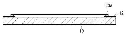
- FIG. 1 is a cross-sectional view showing an example of a transparent surface material with an adhesive layer of the present invention.
- the transparent surface material 1 with an adhesive layer having the protective film 16 includes a transparent surface material 10, a light shielding printing portion 12 formed on the peripheral edge of the surface of the transparent surface material 10, and a transparent surface on which the light shielding printing portion 12 is formed. It has the adhesion layer 14 formed in the surface of the face material 10, and the peelable protective film 16 which covers the surface of the adhesion layer 14.
- the transparent surface material 1 with an adhesive layer shown in FIG. 1 can manufacture a display apparatus by peeling off the protective film 16 and then bonding to the display panel.
- FIG. 1 illustrates the case where the adhesive layer 14 is formed on one side of the transparent surface material 10, the adhesive layer 14 may be formed on both surfaces of the transparent surface material 10.
- the surface of the adhesive layer 14 is also covered with a peelable protective film 16.
- the transparent surface material 10 is preferably a protective plate that is provided on the image display side of the display panel described later and protects the display panel.
- Examples of the transparent face material 10 include a glass plate or a transparent resin plate.
- the transparent surface material 10 has not only high transparency with respect to light emitted from the display panel and reflected light, but also light resistance, low birefringence, high planar accuracy, surface scratch resistance, and high mechanical strength.
- the glass plate is most preferable from the viewpoint of having it.
- it is preferable that the transparent surface material 10 is a glass plate also from the point which permeate
- the material for the glass plate examples include glass materials such as soda lime glass.
- a high transmission glass (white plate glass) having a lower iron content and less bluishness is preferable.
- tempered glass may be used to enhance safety.
- a thin glass plate it is preferable to use a chemically strengthened glass plate.
- the material for the transparent resin plate include highly transparent resin materials (such as polycarbonate and polymethyl methacrylate).
- the transparent face material 10 may be subjected to a surface treatment in order to improve the interfacial adhesive force with the adhesive layer 14.
- a surface treatment method include a method of treating the surface of the transparent face material 10 with a silane coupling agent, a method of forming a silicon oxide thin film by an oxidation flame using a frame burner, and the like.
- the transparent surface material 10 may be provided with an antireflection layer on the surface opposite to the side on which the adhesive layer 14 is formed.
- Examples of the method of providing the antireflection layer include a method of directly forming an inorganic thin film on the surface of the transparent surface material 10, a method of bonding a transparent resin film provided with the antireflection layer to the protective plate 10, and the like. Further, depending on the purpose, a part or the whole of the transparent face material 10 is colored, or a part or the whole of the surface of the transparent face material 10 is polished to form a glass to scatter light, or the surface of the transparent face material 10 is scattered. Further, a minute unevenness or the like may be formed on a part or the whole of the light to refract or reflect the transmitted light. Further, a colored film, a light scattering film, a photorefractive film, a light reflecting film, or the like may be attached to a part or the whole of the surface of the transparent surface material 10.
- the shape of the transparent face material 10 is usually rectangular for the purpose of matching the outer shape of the display device.
- a protective plate that covers the entire display surface of the display panel and has a curved shape in the outer shape can be used. What is necessary is just to set the magnitude
- the size of the transparent surface material 10 is suitably 0.5 m ⁇ 0.4 m or more, and particularly preferably 0.7 m ⁇ 0.4 m or more.
- the upper limit of the size of the transparent surface material 10 is often determined by the size of the display panel. Also, a display device that is too large is likely to be difficult to handle during installation.
- the upper limit of the size of the transparent face material 10 is usually about 2.5 m ⁇ 1.5 m due to these restrictions.
- the thickness of the transparent face material 10 is preferably 0.5 to 25 mm in the case of a glass plate.
- the thickness of the glass is preferably about 0.5 to 1.5 mm in terms of strength.
- the thickness of the transparent resin plate is preferably 2 to 10 mm.
- the light-shielding printing unit 12 hides wiring members and the like connected to the display panel so that areas other than the image display area of the display panel, which will be described later, are not visible from the transparent surface material 10 side.
- the light-shielding printing unit 12 can be formed on the surface on which the adhesive layer 14 is formed or on the opposite surface. In terms of reducing the parallax between the light shielding printing unit 12 and the image display area, it is preferable to form the light shielding printing unit 12 on the surface on the side where the adhesive layer 14 is formed.
- the transparent face material 10 is a glass plate, it is preferable to use ceramic printing containing a black pigment for the light shielding printing portion 12 because of high light shielding properties.
- the light-shielding printing part can also be formed by bonding a transparent film provided with the light-shielding printing part in advance to the protective plate.
- a light shielding printing portion may be provided on the peripheral edge of the transparent film on the surface to be bonded to the protective plate, and a film having an antireflection layer on the back surface thereof, that is, the outermost surface of the display device may be bonded to the protective plate.
- the display panel wiring member has a structure that cannot be seen from the display panel viewing side, or is concealed by another member such as a housing of the display device, or adheres to the bonded surface material other than the display panel
- the light shielding printing portion 12 may not be formed on the transparent face material 10.
- the pressure-sensitive adhesive layer 14 includes a layered portion 18 that extends along the surface of the transparent face material 10, and a weir-shaped portion 20 that touches and surrounds the periphery of the layered portion 18.
- the layered portion 18 is a portion made of a cured product (transparent resin) formed by curing a curable resin composition for forming a layered portion (hereinafter sometimes referred to as “first composition”).
- the weir-shaped portion 20 is formed of a cured product (transparent resin) formed by applying and curing a curable resin composition for forming a weir-shaped portion (hereinafter also referred to as “second composition”). Part.
- the transparent face material 1 with the adhesive layer is composed of a content W1 expressed by mass% of the non-curable oligomer (II) in the layered portion 18 described later and the non-curable oligomer (II ′) in the weir-shaped portion 20.
- the difference (W1 ⁇ W2) from the content W2 expressed in mass% is 40 or less. If the difference (W1-W2) is 40 or less, the difference between the content of the non-curable oligomer (II) in the layered portion and the content of the non-curable oligomer (II ′) in the weir-shaped portion is small.
- the difference (W1-W2) is 40 or less, preferably 30 or less, more preferably 10 or less, and particularly preferably 5 or less. Further, (W1-W2) is preferably more than 0 (that is, W1> W2).
- the measurement of the content W1 of the non-curable oligomer (II) in the layered portion is performed in a region 2 cm or more away from the outermost peripheral portion of the nearest weir-shaped portion in the layered portion. Do. Further, the measurement of the content W2 of the non-curable oligomer (II ′) in the weir-shaped portion is performed in a region separated from the outermost peripheral portion of the weir-shaped portion by a distance half the height of the weir-shaped portion.
- the measurement location in the layered portion As the region, it is possible to eliminate the influence of diffusion of the non-curable oligomer (II) in the vicinity of the interface between the layered portion and the weir-shaped portion. Moreover, even if the outermost peripheral part of a dam-like part touches external air and it becomes inadequate hardening by making the measurement location in a dam-like part into the said area
- the first composition forming the layered portion 18 may be a photocurable resin composition or a thermosetting resin composition.
- the layered portion 18 is preferably a cured product of a photocurable resin composition containing a curable compound and a photopolymerization initiator (C1) because it can be cured at a low temperature and has a high curing rate.
- C1 photopolymerization initiator
- the first photocurable composition is a composition containing a curable compound (I), a non-curable oligomer (II), and a photopolymerization initiator (C1). Moreover, a 1st composition may also contain an additive as needed.
- the first composition preferably has a viscosity at 25 ° C. of 0.05 Pa ⁇ s or more and a viscosity at 40 ° C. of 50 Pa ⁇ s or less, a viscosity at 25 ° C. of 0.2 Pa ⁇ s or more and 40 ° C. More preferably, the viscosity is 10 Pa ⁇ s or less. If the viscosity at 25 ° C.
- the coating shape of the first composition that becomes the layered portion is maintained until the lamination, and after the lamination
- the pressure difference between the pressure in the void (still reduced pressure) and the pressure applied to the adhesive layer (atmospheric pressure) is returned to the atmospheric pressure atmosphere. Since it is easy, a cured film without remaining bubbles can be obtained. If the viscosity at 40 ° C.
- the viscosity of the first composition is measured using an E-type viscometer.
- the viscosity of the first composition can be adjusted by the molecular weight and content ratio of the non-curable oligomer (II). Moreover, it can adjust also by adjusting the molecular weight and content rate of the oligomer (A) mentioned later.
- curable compound (I) The curable compound (I) in the first composition is a urethane acrylate oligomer (A) (hereinafter simply referred to as “oligomer (A)”) and a monomer having a molecular weight of less than 600 and having one or more curable functional groups. (B). It is preferable that curable compound (II) consists of an oligomer (A) and a monomer (B).
- the monomer (B) preferably contains a monomer (B1) having a hydroxyl group. Such a hydroxyl group remains in the layered portion made of the cured product of the first composition containing the monomer (B1). The presence of such a hydroxyl group contributes to the stabilization of the non-curable oligomer (II) in the layered portion.
- the number average molecular weight of the oligomer (A) is preferably from 1,000 to 100,000, more preferably from 10,000 to 70,000, particularly preferably from 10,000 to 40,000. When the number average molecular weight of the oligomer (A) is in this range, the viscosity of the first composition is easily adjusted to the above range.
- the number average molecular weight of the oligomer (A) is a polystyrene equivalent number average molecular weight obtained by measurement by gel permeation chromatography (GPC). In the GPC measurement, when a peak of an unreacted low molecular weight component (monomer or the like) appears, the number average molecular weight is determined by excluding the peak.
- the oligomer (A) has an acryloyloxy group.
- the average number of acryloyloxy groups per molecule of the oligomer (A) is preferably 1.8 to 4 from the viewpoints of curability of the first composition and mechanical properties of the layered portion.
- 1 type may be sufficient as an oligomer (A) and 2 or more types may be sufficient as it.
- oligomer (A1) A polyurethane acrylate oligomer obtained by reacting a polyol and polyisocyanate to obtain a prepolymer having an isocyanate group at the terminal, and then reacting the isocyanate group of the prepolymer with the following monomer (a1).
- Monomer (a1) A monomer having a molecular weight of 125 to 600, having one or more acryloyloxy groups and one group that reacts with an isocyanate group.
- Examples of the monomer (a1) include a monomer having an active hydrogen group (hydroxyl group, amino group, etc.) and an acryloyloxy group.
- Specific examples of the monomer (a1) include hydroxyalkyl acrylates having a C 2-6 hydroxyalkyl group (2-hydroxyethyl acrylate, 2-hydroxypropyl acrylate, 2-hydroxybutyl acrylate, 4-hydroxybutyl acrylate, etc.).
- the monomer (a1) to be reacted with the prepolymer is preferably a hydroxyalkyl acrylate having a hydroxyalkyl group having 2 to 4 carbon atoms.
- polyol and polyisocyanate known compounds can be used.
- polyol (i), diisocyanate (ii) and the like described as raw materials for the urethane-based oligomer (a) described in International Publication No. 2009/016943 can be mentioned.
- polyol examples include polyoxyalkylene polyol (polyoxyethylene glycol, polyoxypropylene polyol, etc.), polyester polyol, and polycardnate polyol.
- polyol polyoxyalkylene polyol
- polyoxypropylene polyol is more preferable.
- a polyol may be used individually by 1 type and may use 2 or more types together.
- the polyisocyanate is preferably at least one diisocyanate selected from the group consisting of aliphatic diisocyanates, alicyclic diisocyanates and non-yellowing aromatic diisocyanates.
- aliphatic polyisocyanate examples include hexamethylene diisocyanate, 2,2,4-trimethyl-hexamethylene diisocyanate, and 2,4,4-trimethyl-hexamethylene diisocyanate.
- Examples of the alicyclic polyisocyanate include 3-isocyanatomethyl-3,5,5-trimethylcyclohexyl isocyanate (also known as isophorone diisocyanate), methylenebis (4-cyclohexyl isocyanate), and the like.
- non-yellowing aromatic diisocyanate examples include xylylene diisocyanate. Polyisocyanate may be used individually by 1 type and may use 2 or more types together.
- the following monomer (a2) may be used as a diluent.
- the diluent remains in the obtained oligomer (A1) and becomes a part of the monomer (B) in the curable compound (I).
- Monomer (a2) A monomer having a molecular weight of 125 to 600, having at least one curable functional group, and having no group capable of reacting with an isocyanate group.
- a monomer (B21) described later is preferable.
- Monomer (B) The molecular weight of the monomer (B) is less than 600, preferably 125 or more and less than 600, and more preferably 140 to 400. The smaller the molecular weight of the monomer (B), the better the adhesion between the transparent surface material and the layered portion. If the molecular weight of the monomer (B) is equal to or higher than the lower limit value, volatilization of the monomer (B) when the display device is produced by the below-described reduced pressure laminating method can be suppressed.
- the monomer (B) may be one type or two or more types.
- the number of curable functional groups per molecule of the monomer (B) is one or more, the curability of the first resin composition 26, and the machine of the layered portion 18 obtained by curing the first resin composition 26 From the viewpoint of physical characteristics, 1 to 3 is preferable.
- the curable compound (I) it is more preferable to use a monomer (B) having one curable functional group and a monomer (B) having two or more curable functional groups.
- the curable functional group of the monomer (B) include addition polymerizable unsaturated groups (acryloyl group, methacryloyl group, acryloyloxy group, methacryloyloxy group, etc.), combinations of unsaturated groups and thiol groups, and the like.
- the curable functional group of the monomer (B) is preferably a group selected from an acryloyloxy group and a methacryloyloxy group from the viewpoint of a high curing rate and a highly transparent layered portion, and the oligomer (A) and the monomer A methacryloyloxy group is particularly preferred because the difference in reactivity of the curable functional group with (B) is reduced and a homogeneous layered portion is obtained.
- the monomer (B1) contributes to the stabilization of the non-curable oligomer (II). Moreover, the favorable adhesiveness of a transparent surface material and a layer part is obtained by containing a monomer (B1).
- the number of hydroxyl groups in the monomer (B1) is preferably 1 or 2.
- Examples of the monomer (B1) having one hydroxyl group include 2-hydroxyethyl (meth) acrylate, 2-hydroxypropyl (meth) acrylate, 2-hydroxybutyl (meth) acrylate, 4-hydroxybutyl (meth) acrylate, 6- Examples thereof include hydroxyhexyl methacrylate.
- Examples of the monomer (B1) having two hydroxyl groups include glycerin monomethacrylate and 2,3-dihydroxypropyl acrylate.
- the monomer (B1) is preferably a hydroxy methacrylate having a hydroxyalkyl group having 1 to 2 hydroxyl groups and 3 to 8 carbon atoms (2-hydroxypropyl methacrylate, 2-hydroxybutyl methacrylate, 4-hydroxybutyl methacrylate, etc.). 2-hydroxybutyl methacrylate is particularly preferred.
- the monomer (B1) may be one type or two or more types.
- Monomer (B2) A monomer having one or more curable functional groups, a molecular weight of less than 600, and no hydroxyl group. A monomer (B2) contributes to providing the softness
- the following monomer (B21) is preferable.
- the content of the monomer (B21) is larger than the content of the monomer (B1) by mass ratio, a laminate in which an adhesive layer is formed on a transparent surface material and a display panel are bonded in a reduced pressure atmosphere. After bonding the face material, when it is returned to the atmospheric pressure atmosphere, the time until the void generated in the adhesive layer disappears tends to be shortened. On the other hand, when the monomer (B21) is contained, the time required for curing the first composition tends to be long.
- Monomer (B21) A methacrylate having no hydroxyl group and having an alkyl group having 8 to 22 carbon atoms or a cyclic alkyl group.
- Examples of the monomer (B21) include n-dodecyl methacrylate, n-octadecyl methacrylate, n-behenyl methacrylate, isobornyl methacrylate, adamantyl methacrylate and the like.
- n-dodecyl methacrylate and n-octadecyl methacrylate are preferable.
- the monomer (B2) may be one type or two or more types.
- the ratio of the oligomer (A) to the total (100% by mass) of the oligomer (A) and the monomer (B) in the first composition is preferably 20 to 90% by mass, and more preferably 30 to 80% by mass. If the ratio of the oligomer (A) is at least the lower limit value, the heat resistance of the layered portion will be good. If the ratio of this oligomer (A) is below an upper limit, the curability of a 1st composition and the adhesiveness of a transparent surface material and a layer part will become favorable.
- the ratio of the monomer (B) to the total (100% by mass) of the oligomer (A) and the monomer (B) in the first composition is preferably 10 to 80% by mass, and more preferably 20 to 70% by mass.
- the ratio of the monomer (B1) to the total (100% by mass) of the oligomer (A) and the monomer (B) in the first composition is preferably 10 to 60% by mass, and more preferably 20 to 50% by mass.
- the ratio of the monomer (B2) to the total (100% by mass) of the oligomer (A) and the monomer (B) in the first composition is preferably 5 to 50% by mass, and more preferably 15 to 40% by mass. If the ratio of the monomer (B2) is at least the lower limit value, the effect of adding the monomer (B2) can be sufficiently obtained.
- Non-curable oligomer (II) is an oligomer having a hydroxyl group that does not undergo a curing reaction with the curable compound (I) when the first composition is cured. Furthermore, it is an oligomer having a hydroxyl group that does not undergo a curing reaction with the curable compound (I) even when the second composition described later (that is, the curable resin composition for forming a weir-like portion) is cured.
- the average number of hydroxyl groups per molecule of non-curable oligomer (II) is preferably 0.8 to 3, more preferably 1.8 to 2.3.
- the number average molecular weight (Mn) per hydroxyl group of the non-curable oligomer (II) is preferably 400 to 8000. If the number average molecular weight per hydroxyl group is 400 or more, the polarity of the non-curable oligomer (II) does not become too high, and good compatibility with the curable compound (I) in the first composition is obtained. It is easy to be done.
- the interaction between the hydroxyl group derived from the curable compound (I) and the hydroxyl group of the non-curable oligomer (II) causes the layered portion after curing to It is easy to obtain the effect of stabilizing the non-curable oligomer (II). Such an interaction is presumed to involve hydrogen bonding.
- a 1st composition can be made low viscosity by containing in a 1st composition.
- Non-curable oligomer (II) may be used individually by 1 type, and may use 2 or more types together.
- non-curable oligomer (II) examples include a high molecular weight polyol.
- polyoxyalkylene polyol examples include polyoxyalkylene diols such as polyoxyethylene glycol, polyoxypropylene diol, polyoxypropylene triol, and polyoxytetramethylene glycol.
- the number average molecular weight (Mn) per hydroxyl group of the polyoxyalkylene polyol is preferably 400 to 8000, more preferably 600 to 5000.
- polyester polyol a residue of an aliphatic diol (ethylene glycol, propylene glycol, 1,4-butanediol, etc.) and a residue of an aliphatic dicarboxylic acid (glutaric acid, adipic acid, sebacic acid, etc.) are used. Examples thereof include aliphatic polyester diols.
- the number average molecular weight (Mn) per hydroxyl group of the polyester polyol is preferably 400 to 8000, more preferably 800 to 6000.
- polycarbonate polyol examples include an aliphatic polycarbonate diol having a residue of a diol (such as 1,6-hexanediol) and an aliphatic polycarbonate diol such as a ring-opening polymer of an aliphatic cyclic carbonate.
- the number average molecular weight (Mn) per hydroxyl group of the polycarbonate polyol is preferably 400 to 8000, more preferably 800 to 6000.
- the number average molecular weight of the non-curable oligomer (II) in the present specification is the hydroxyl value P (mg KOH / g) measured according to JIS K 1557-1 (2007 edition) and the non-curable oligomer (II) 1 This is a value calculated by the following formula (1) from the average number Q of hydroxyl groups per molecule.
- Molecular weight of non-curable oligomer (II) 56.1 ⁇ Q ⁇ 1000 / P (1)
- a polyoxyalkylene polyol is preferably used as the non-curable oligomer (II) in that the elastic modulus of the layered portion after curing tends to be lower, and a polyoxyethylene polyoxypropylene polyol having an oxypropylene group and an oxyethylene group Alternatively, polyoxypropylene polyol is preferably used, and polyoxypropylene polyol is particularly preferable in terms of low viscosity.
- oligomer (A) and noncurable oligomer (II) Preferably have molecular chains having the same structure or a similar structure.
- a compound having a hydroxyl group hereinafter referred to as “hydroxyl group-containing compound” is used as a raw material for the oligomer (A) in the first composition, and the same hydroxyl group-containing compound is converted into a non-curable oligomer (II).
- hydroxyl group-containing compound a compound having a hydroxyl group
- the oligomer (A) is a urethane acrylate oligomer synthesized using polyoxyalkylene polyol and polyisocyanate as raw materials, and the non-curable oligomer (II) is a polyoxyalkylene polyol. It is particularly preferable in terms of solubility.
- the hydroxyl group-containing compound used as the raw material of the oligomer (A) and the hydroxyl group-containing compound used as the non-curable oligomer (II) are not the same, the hydroxyl group-containing compound has a part such as a molecular chain having a common repeating unit. It is preferable that they have a common structure and have the same polarity. If the oligomer (A) and the non-curable oligomer (II) partially have the same molecular structure, the compatibility of the non-curable oligomer (II) in the composition is further increased.
- Examples of the method for adjusting the polarity of the hydroxyl group-containing compound include a method for introducing a polar group and a method for producing a hydroxyl group-containing compound having an oxypropylene group and an oxyethylene group. Introducing a polar group increases the polarity of the hydroxyl group-containing compound. Moreover, if it has an oxypropylene group and an oxyethylene group, the polarity of a hydroxyl-containing compound will go up. These methods may be used in combination.
- the oligomer (A) is a urethane acrylate oligomer synthesized using a polyoxyethylene polyoxypropylene polyol having an oxypropylene group and an oxyethylene group and a polyisocyanate as raw materials
- the non-curable oligomer (II) is A combination which is a polyoxypropylene polyol having no oxyethylene group and having a molecular weight per hydroxyl group smaller than that of the polyol used as the oligomer (A).
- the combination of the curable compound (I) and the non-curable oligomer (II) contained in the first composition includes a curable compound (I-1) containing the following oligomer (A12) and monomer (B1), A combination of curable oligomer (II-1) is most preferred.
- Oligomer (A12) A polyoxyethylene polyoxypropylene diol having an oxypropylene group and an oxyethylene group is reacted with a polyisocyanate to obtain a prepolymer having an isocyanate group at the terminal, and then reacted with the monomer (a1).
- Non-curable oligomer (II-1) The same polyoxyethylene polyoxypropylene diol having an oxypropylene group and an oxyethylene group as the raw material of the oligomer (A12).
- Non-curable oligomer (II-2) A polyoxypropylene diol having no oxyethylene group and having a molecular weight smaller than that of the polyoxyethylene polyoxypropylene diol as a raw material of the oligomer (A12).
- the non-curable oligomer (II) in the first composition is in an atmospheric pressure atmosphere after laminating the laminate in which the adhesive layer is formed on the transparent surface material and the surface material to be bonded in a reduced pressure atmosphere. When it returns, it contributes to shortening of time required for the space
- the content of the non-curable oligomer (II) in the first composition (100% by mass) is preferably 10 to 70% by mass, and more preferably 26 to 60% by mass. If the content of the non-curable oligomer (II) is not less than the lower limit value, voids are unlikely to remain in the adhesive layer.
- the layered portion of the adhesive layer is easily cured. If the layered portion is sufficiently cured, it becomes easy to peel the protective film from the cured adhesive layer.
- a chain transfer agent also contributes to shortening of time until the space
- the non-curable oligomer (100% by mass) in the first composition (100% by mass) is preferably 40 to 70% by mass, and more preferably 50 to 70% by mass.
- the content of the non-curable oligomer (II) in the first composition (100% by mass) is more preferably 30 to 70% by mass, and further preferably 40 to 70% by mass.
- the content of the non-curable oligomer (II) in the composition (100% by mass) is preferably 40 to 70% by mass, and more preferably 50 to 70% by mass.
- the first composition contains monomer (B1) and monomer (B2), the mass ratio of monomer (B2) to monomer (B1) is 1 to 3, and 1 to 100 parts by mass of curable compound (I).
- the chain transfer agent is contained in an amount of not more than part by mass
- the content of the non-curable oligomer (II) in the first composition (100% by mass) is more preferably 5 to 55% by mass, and 10 to 50% by mass. More preferred is 35 to 50% by mass.
- oligomer (A): monomer (B): non-curable oligomer (II) Content ratio (% by mass) is preferably 6 to 80: 3 to 70:10 to 70. If it is this range, a 1st composition can be made into a suitable viscosity.
- Photopolymerization initiator (C1) examples include acetophenone series, ketal series, benzoin or benzoin ether series, phosphine oxide series, benzophenone series, thioxanthone series, and quinone series.
- phosphine oxide and thioxanthone photopolymerization initiators are preferable, and phosphine oxide is particularly preferable in terms of suppressing coloring after the photopolymerization reaction.
- the content of the photopolymerization initiator (C1) in the first photocurable composition is preferably 0.01 to 10 parts by mass with respect to 100 parts by mass in total of the oligomer (A) and the monomer (B). 1 to 5 parts by mass is more preferable.
- Additives include polymerization inhibitors, photocuring accelerators, chain transfer agents, light stabilizers (ultraviolet absorbers, radical scavengers, etc.), antioxidants, flame retardants, adhesion improvers (silane couplings) Agents), pigments, dyes and the like.
- a polymerization inhibitor and a light stabilizer are preferable.
- a polymerization inhibitor in an amount smaller than that of the polymerization initiator, the stability of the first composition can be improved, and the molecular weight of the layered portion after curing can also be adjusted.
- Polymerization inhibitors such as hydroquinone (2,5-di-tert-butylhydroquinone, etc.), catechol (p-tert-butylcatechol, etc.), anthraquinone, phenothiazine, hydroxytoluene, etc. Agents.
- the light stabilizer include ultraviolet absorbers (benzotriazole-based, benzophenone-based, salicylate-based, etc.), radical scavengers (hindered amine-based), and the like.
- the antioxidant include phosphorus compounds and sulfur compounds.
- the content of the additive in the first composition is preferably 10 parts by mass or less and more preferably 5 parts by mass or less with respect to 100 parts by mass in total of the oligomer (A) and the monomer (B).
- the chain transfer agent When the chain transfer agent is contained in the first composition, there is a tendency that the time until the gap generated at the time of bonding with the bonded surface material on which the adhesive layer is formed on the transparent surface material disappears is shortened. Therefore, if a chain transfer agent is used, the addition amount of non-curable oligomer (II) necessary for obtaining the effect of eliminating the voids can be reduced. When the addition amount of the non-curable oligomer (II) is small, the difference in curing shrinkage between the weir-like portion and the layer-like portion tends to be small. On the other hand, in order to obtain a good curing rate, it is preferable that the chain transfer agent is not contained or only a small amount is contained. When the chain transfer agent is contained, the amount added is preferably 1 part by mass or less, more preferably 0.5 parts by mass or less, with respect to 100 parts by mass in total of the oligomer (A) and the monomer (B).
- the thickness of the layered portion 18 is preferably 0.03 to 2 mm, and more preferably 0.1 to 0.8 mm. If the thickness of the layered portion 18 is equal to or greater than the lower limit value, the layered portion 18 can effectively buffer an impact caused by an external force from the transparent surface material 10 side, and the display panel can be protected. Moreover, even if the foreign material which does not exceed the thickness of the layered part 18 mixes between those to-be-bonded surface materials, such as a display panel, and the transparent surface material 1 with an adhesion layer, of the layered part 18 There is little influence on the light transmission performance without the thickness changing greatly. If the thickness of the layered portion 18 is less than or equal to the upper limit value, voids are unlikely to remain in the layered portion 18, and when the display device is formed, the overall thickness does not increase more than necessary.
- the storage shear modulus at 35 ° C. of the layered portion 18 is preferably 1.0 to 100 kPa.
- the upper limit of the storage shear modulus of the layered portion 18 is more preferably 25 kPa, and even more preferably 12 kPa. If the storage shear modulus is 1.0 kPa or more, the shape of the layered portion 18 is easily maintained. Further, even when the thickness of the layered portion 18 is relatively large, the thickness can be maintained uniformly throughout the layered portion 18, and when the transparent surface material with an adhesive layer 1 and the object to be bonded are bonded, It is preferable because voids hardly occur at the interface between the bonded body and the adhesive layer 14.
- the storage shear modulus is 100 kPa or less
- the object to be bonded is returned to the atmospheric pressure atmosphere.
- the void generated at the interface between the adhesive layer 14 and the adhesive layer 14 disappears in a short time and is difficult to remain, which is preferable.
- the second composition forming the weir 20 may be a photocurable resin composition or a thermosetting resin composition.
- the weir-like portion 20 is preferably a cured product of a photocurable resin composition containing a curable compound and a photopolymerization initiator (C2) from the viewpoint that it can be cured at a low temperature and has a high curing rate.
- C2 photopolymerization initiator
- a second composition having the same composition as the first composition used for forming the layered portion is applied to the peripheral edge of the surface of the transparent face material and semi-cured, before being cured in the step (d) described later. It is good also as an uncured weir-like part.
- the photocurable second composition suitable for the present invention will be described.
- the photocurable second composition is a composition containing a curable compound (I ′), a non-curable oligomer (II ′), and a photopolymerization initiator (C2).
- a 2nd composition may also contain an additive as needed.
- the viscosity at 25 ° C. of the second composition is preferably 10 to 3000 Pa ⁇ s, preferably 300 to 3000 Pa ⁇ s, more preferably 500 to 2800 Pa ⁇ s, still more preferably 800 to 2500 Pa ⁇ s, and 1000 to 2000 Pa ⁇ s. Is particularly preferred. If the viscosity at 25 ° C. of the second composition is equal to or higher than the lower limit, the shape of the uncured weir-shaped portion can be easily maintained for a relatively long time, and the height of the uncured weir-shaped portion can be sufficiently maintained. If the viscosity of the second composition is not more than the upper limit value, an uncured weir-like portion can be formed by coating.
- the viscosity of the uncured weir-shaped portion after the light irradiation may be set to the above-mentioned preferable range.
- the viscosity at the time of application of the second composition is preferably 300 Pa ⁇ s or less, and more preferably 200 Pa ⁇ s or less.
- the lower limit of the viscosity of the second composition in this case is not particularly limited, but is preferably 0.01 Pa ⁇ s or more.
- the viscosity of the second composition is measured using an E-type viscometer at 25 ° C.
- the curable compound (I ′) includes a urethane acrylate oligomer (A ′) (hereinafter simply referred to as “oligomer (A ′)”) and a monomer having a molecular weight of less than 600 (B ′) having at least one curable functional group. ) And.
- the curable compound (II ′) is preferably composed of an oligomer (A ′) and a monomer (B ′). As an oligomer (A ') and a monomer (B'), what was mentioned by the oligomer (A) and the monomer (B) is mentioned, for example.
- the oligomer (A ′) an average of 1 curable group per molecule is considered from the viewpoint of the curability of the second composition and the mechanical properties of the weir 20 obtained by curing the second composition. Those having from 8 to 4 are preferred.
- the monomer (B ′) preferably contains a monomer (B′1) having a hydroxyl group. Such a hydroxyl group remains in the weir-shaped portion made of the cured product of the second composition containing the monomer (B′1). The presence of such a hydroxyl group contributes to the stabilization of the non-curable oligomer (II ′) in the weir-like portion.
- the curable functional group of the monomer (B′1) is preferably an acryloyloxy group.
- the monomer (B ′) may include a monomer (B′2) other than the monomer (B′1).
- Examples of the monomer (B′2) include the same compounds as the monomer (B2). However, unlike the monomer (B2), methacrylate is also preferable as the acrylate.
- the monomer (B′2) can be used as a diluent in the synthesis of the oligomer (A ′), similarly to the monomer (B2).
- As the monomer (B′2) a monomer having at least one (meth) acryloyloxy group, a molecular weight of less than 600, and having no hydroxyl group is preferable.
- (meth) acrylate having an alkyl group having 8 to 22 carbon atoms or a cyclic alkyl group n-dodecyl (meth) acrylate, n-octadecyl (meth) acrylate, n-behenyl (meth)) Acrylate, isobornyl (meth) acrylate, adamantyl (meth) acrylate, etc.
- the curable compound (I ′) used in the second composition is preferably the same as the curable compound (I) used in the first composition, but may be different.
- the number average molecular weight of the oligomer (A ′) is preferably 30,000 to 100,000, more preferably 40,000 to 80,000, further preferably 50,000 to 70,000, more preferably 50,000 in that the viscosity of the uncured weir-shaped portion can be easily controlled within the above range. More preferred is ⁇ 65000. Since the oligomer (A ′) having a number average molecular weight of 30,000 to 100,000 is high in viscosity, it is difficult to synthesize by an ordinary method, and even if synthesized, it is difficult to mix with the monomer (B ′).
- the obtained product is used as it is, or the obtained product is used as it is. Further, it is preferably diluted with a monomer (B′1) described later and used as the curable compound (I ′).
- Examples of the monomer (B′1) having a hydroxyl group include hydroxy acrylates having a hydroxyalkyl group having 1 to 2 hydroxyl groups and 3 to 8 carbon atoms (2-hydroxypropyl acrylate, 2-hydroxybutyl acrylate, 4-hydroxybutyl acrylate, 6-hydroxyhexyl acrylate, etc.) or hydroxy methacrylate (2-hydroxypropyl methacrylate, 2-hydroxybutyl methacrylate, 4-hydroxybutyl methacrylate, 6-hydroxyhexyl methacrylate, etc.) is preferred, 4-hydroxybutyl acrylate, or 2- Hydroxybutyl methacrylate is particularly preferred.
- Monomer (B) may be used alone or in combination of two or more.
- the non-curable oligomer (II ′) is an oligomer having a hydroxyl group that does not undergo a curing reaction with the curable compound (I ′) when the second composition is cured. Furthermore, it is an oligomer having a hydroxyl group that does not undergo a curing reaction with the curable compound (I) even when the first composition is cured. Further, the non-curable oligomer (II ′) is preferably the same or similar to the non-curable oligomer (II), and the same oligomer is most preferable.
- the same thing means the same type and number of repeating units.
- the oligomer is composed of different types or numbers of repeating units, it is preferable that the oligomer is similar. Similar oligomers are oligomers having the same main repeating unit and different numbers. As the similar oligomer, those containing the same repeating unit are preferably 30% by mass or more, more preferably 50% by mass or more. If a polyoxyalkylene polyol is used as the non-curable oligomer (II), the elastic modulus of the weir-like part 20 after curing tends to be lower.
- the ratio of the oligomer (A ′) to the total (100% by mass) of the oligomer (A ′) and the monomer (B ′) in the second composition is preferably 20 to 90% by mass, more preferably 30 to 80% by mass. preferable.
- the proportion of the oligomer (A ′) is at least the lower limit value, the heat resistance of the weir-like portion is good. If the ratio of this oligomer (A ') is below an upper limit, sclerosis
- the non-curable oligomer (II) in the first composition is the same type of polyol as the polyol used in the oligomer (A ′), the proportion of the oligomer (A ′) in the second composition is small However, it is easy to suppress diffusion of the non-curable oligomer (II) from the layered portion to the weir-shaped portion.
- the ratio of the monomer (B ′) to the total (100 mass%) of the oligomer (A ′) and the monomer (B ′) in the second composition is preferably 15 to 70 mass%, more preferably 15 to 50 mass%. It is preferably 20 to 45% by mass, more preferably 25 to 40% by mass.
- the content of the non-curable oligomer (II ′) in the second composition depends on the content of the non-curable oligomer (II) in the first composition, and the difference (W1 ⁇ W2) is the predetermined value described above. Set to be less than the difference.
- the content of the non-curable oligomer (II ′) in the second composition is preferably 1% by mass or more, more preferably 2% by mass or more, and particularly preferably 5% by mass or more.
- the content of the non-curable oligomer (II) in the first composition is such that the difference (W1-W2) is 40 or less. However, it is preferably 65% by mass or less from the viewpoint of adhesion to the face material. Further, when the non-curable oligomer (II ′) is contained in the second composition, the refractive index of the dam-like portion and the layer-like portion becomes close in the formed adhesive layer, so that the boundary between the dam-like portion and the layer-like portion Can be made invisible.
- Photopolymerization initiator (C2) examples of the photopolymerization initiator (C2) contained in the photocurable second composition include acetophenone series, ketal series, benzoin or benzoin ether series, phosphine oxide series, benzophenone series, thioxanthone series, and quinone series. Initiators are mentioned. Among these, as the photopolymerization initiator (C2), acetophenone-based, ketal-based, and benzoin ether-based photopolymerization initiators are preferable. When curing with visible light having a short wavelength, a phosphine oxide-based photopolymerization initiator is more preferable from the viewpoint of the absorption wavelength region. By using two or more kinds of photopolymerization initiators (C2) having different absorption wavelength ranges, the curing time can be further accelerated and the surface curability in the weir-like portion can be increased.
- the content of the photopolymerization initiator (C2) in the photocurable second composition is 0.01 to 10 parts by mass with respect to 100 parts by mass in total of the oligomer (A ′) and the monomer (B ′). Preferably, 0.1 to 5 parts by mass is more preferable.
- additive added to the second composition examples include the same additives as those mentioned for the first composition.
- a polymerization inhibitor and a light stabilizer are preferable.
- a polymerization inhibitor in an amount less than the polymerization initiator, the stability of the second composition can be improved, and the molecular weight of the weir-like portion after curing can also be adjusted.
- the total amount of these additives is preferably 10 parts by mass or less, and more preferably 5 parts by mass or less with respect to 100 parts by mass in total of the oligomer (A ′) and the monomer (B ′).
- the width of the weir 20 is narrow in this application.
- the width of the weir 20 is preferably 0.5 to 2 mm, and more preferably 0.8 to 1.6 mm.
- the thickness of the dam-like part 20 is slightly larger than the thickness of the layered part 18 in that a void open to the outside is hardly generated when the bonded surface material and the transparent surface material 1 with the adhesive layer are bonded.
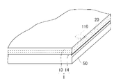
- the thickness of the weir-like portion 20 is larger than the thickness of the layer-like portion 18, as shown in FIG. 13, when the display panel 50 and the laminate 1 are bonded together, Even if the gap 110 remains at the interface between the adhesive layer 14 and the adhesive layer 14, the gap 110 is blocked by the weir-like portion 20, so that the gap 110 does not open to the outside and becomes an independent gap 110.
- the difference between the thickness of the dam-like portion 20 and the thickness of the layer-like portion 18 is preferably 0.05 mm or less, and more preferably 0.03 mm or less, from the viewpoint of suppressing generation of a gap due to a step between the dam-like portion 20 and the layer-like portion 18. .
- the difference between the thickness of the weir 20 and the thickness of the layer 18 is obtained by measuring the total thickness of the transparent surface 10 and the layer 18 or the weir 20 formed thereon using a laser displacement meter. Find from the difference.
- the thickness of the layered portion 18 is the thickness of the peripheral portion of the layered portion 18 in contact with the weir-shaped portion 20.
- the storage shear elastic modulus at 35 ° C. of the weir 20 may be a lower limit of the shear elastic modulus at which the weir 20 can be self-supported, and the upper limit may be 15 times the storage shear elastic modulus of the layer 18 at 35 ° C. More specifically, it is preferably 1 to 150 kPa. By setting the storage shear elastic modulus at 35 ° C. of the weir 20 to 1 kPa or more, the weir 20 can be made independent.
- the storage shear elastic modulus at 35 ° C. of the weir 20 is larger than the storage shear elastic modulus at 35 ° C. of the layered portion 18. If the storage shear elastic modulus of the weir-like part 20 is larger than the storage shear elastic modulus of the layered part 18, when the display panel and the transparent surface material 1 with the adhesive layer are bonded together, Even if voids remain at the interface between the display panel and the adhesive layer 14, the voids are not easily opened to the outside and are likely to become independent voids.
- the transparent surface material 1 with an adhesion layer and a to-be-bonded body are bonded by making the storage shear elastic modulus in 35 degreeC of the weir-like part 20 into 15 times or less of the storage shear elastic modulus in 35 degreeC of the layered part 18.
- the display nonuniformity by the difference in the storage shear elastic modulus of the dam-like part 20 and the layered part 18 can be suppressed.
- the storage shear elastic modulus at 35 ° C. of the weir-shaped portion made of a cured product of the photocurable resin composition is a value measured by the following method.
- the storage shear modulus at 35 ° C. of the layered portion is a value measured in the same manner.
- the storage shear modulus at 35 ° C. of the weir 20 after curing was measured using a rheometer (manufactured by Anton titanium, modular rheometer Physica MCR-301) and a measuring spindle and a transparent plate.
- an uncured second resin composition is disposed in the gap, and curing is performed while irradiating the uncured second resin composition with light necessary for curing.
- the storage shear modulus of the process was measured, and the measured value under the curing conditions when forming the weir 20 was defined as the storage shear modulus of the weir 20.
- the protective film 16 is required not to be firmly adhered to the adhesive layer 14 and to be able to be attached to a support surface material in the manufacturing method of the present invention described later. Therefore, the protective film 16 is preferably a self-adhesive protective film in which one side of a base film having relatively low adhesion, such as polyethylene, polypropylene, and fluorine resin, is an adhesive surface.
- the adhesive strength of the adhesive surface of the protective film 16 is preferably 0.01 to 0.1 N, preferably 0.02 to 0.06 N in a 50 mm wide specimen in a 180 degree peel test with a peel rate of 300 mm / min. Is more preferable. If the said adhesive force is more than a lower limit, sticking to a support surface material is possible. If the said adhesive force is below an upper limit, it is easy to peel the protective film 16 from a support surface material.
- the thickness of the protective film 16 varies depending on the resin to be used, but when a relatively flexible film such as polyethylene or polypropylene is used, it is preferably 0.04 to 0.2 mm, more preferably 0.06 to 0.1 mm. . If the thickness of the protective film 16 is equal to or greater than the lower limit value, deformation of the protective film 16 can be suppressed when the protective film 16 is peeled from the adhesive layer 14. If the thickness of the protective film 16 is not more than the upper limit value, the protective film 16 is easily bent at the time of peeling, and the protective film 16 is easily peeled off from the adhesive layer 14.
- a back layer on the back surface opposite to the adhesive surface of the protective film 16
- peeling from the adhesive layer 14 can be further facilitated.
- a film with relatively low adhesion such as polyethylene, polypropylene, and fluorine resin.
- a release agent such as silicone may be applied to the protective film 16 within a range that does not adversely affect the adhesive layer 14.
- a barrier layer that prevents gas (oxygen gas, nitrogen gas, water vapor, etc.) from passing through the protective film 16 and entering the adhesive layer 14 from a part of the protective film.
- the content W1 (% by mass) of the non-curable oligomer (II) contained in the layered portion and the content W2 of the non-curable oligomer (II ′) contained in the weir-shaped portion Since the difference (W1-W2) with respect to (mass%) is 40 or less, defects will occur in the layered portion and the weir-shaped portion even after a predetermined time has elapsed after bonding with the surface material to be bonded. Difficult to improve product reliability.
- the transparent surface material 1 with the adhesion layer of the example of illustration is an example whose transparent surface material is a protective plate of a display apparatus
- the transparent surface material with an adhesion layer of this invention is not limited to the thing of an example of illustration. Any transparent surface material with an adhesive layer in which a specific adhesive layer is formed on at least one surface of the transparent surface material may be used.
- the transparent surface material with an adhesive layer of the present invention may be a transparent surface material with an adhesive layer in which a specific adhesive layer is formed on both surfaces of the transparent surface material.
- polarizing means film-like absorption polarizer, wire grid polarizer, etc.
- Light modulation means a retardation film such as a quarter-wave plate, a retardation film patterned in a stripe shape, or the like
- the method for producing a transparent surface material with an adhesive layer of the present invention having a protective film is a method having the following steps (a) to (e).
- the first composition is contained between the transparent surface material in a reduced pressure atmosphere and the protective film adhered to the support surface material, under a high pressure atmosphere such as an atmospheric pressure atmosphere, In this method, the encapsulated first composition is cured to form a layered portion.
- the method of containing the first composition under reduced pressure is not a method of injecting the first composition into a narrow and wide space between the transparent surface material and the protective film adhered to the support surface material, but a transparent surface material.
- the first composition is supplied to almost the entire surface of the first composition, and the first composition is then placed between the transparent surface material and the protective film adhered to the supporting surface material by stacking the protective film adhered to the supporting surface material.
- Adopt a method to contain
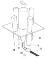
- a photocurable liquid second composition is applied by a dispenser 30 or the like along the light-shielding printing portion 12 at the peripheral edge of the transparent face material 10, and the uncured weir-like portion 20 ⁇ / b> A.
- coating of a 2nd composition is performed using a printing machine, a dispenser, etc.
- step (a) for example, as shown in FIGS.
- the uncured weir 20A may be in an uncured state where no curing reaction is performed, or may be in a partially cured state that is partially cured. Partial curing in the uncured weir 20A is performed by light irradiation when the second composition is a photocurable resin composition.
- the photocurable resin composition is partially cured by irradiating ultraviolet light or short wavelength visible light from a light source (ultraviolet lamp, high pressure mercury lamp, UV-LED, etc.).
- a plurality of UV-LED light sources 31 are disposed so as to surround the dispenser 30, so that a transparent surface material (protection plate)
- the second resin composition 21 applied on the substrate 10 can be uniformly exposed and cured immediately after application.
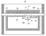
- a liquid first composition 26 is supplied to a rectangular region 24 surrounded by the uncured weir-like portion 20 ⁇ / b> A on the transparent face material 10.
- the supply of the first composition 26 is performed by placing the transparent surface material 10 flat on the lower platen 28 and moving the first composition 26 into a linear or belt shape by a dispenser 30 that moves in the horizontal direction. Or it implements by supplying in a dot form.
- the dispenser 30 of this example is horizontally movable over the entire range of the region 24 by a known horizontal movement mechanism including a pair of feed screws 32 and a feed screw 34 orthogonal to the feed screw 32.
- the supply amount of the first composition 26 is such that the space formed by the uncured weir 20A, the transparent face material 10 and the protective film 16 is filled with the first composition 26, so that the transparent face material 10 and the protective film 16 are filled. Is set in advance to a predetermined interval (that is, the layered portion 18 has a predetermined thickness). At this time, it is preferable to consider in advance volume reduction due to curing shrinkage of the first composition 26. Therefore, the supply amount of the first composition 26 is preferably such that the thickness of the layered portion 18 before curing is slightly larger than the predetermined thickness of the layered portion 18 after curing.
- the peripheral portion of the first composition 26 spreads outward, and the peripheral portion is prevented from being thinned, and the entire thickness of the first composition 26 is made uniform. Can keep. By making the entire thickness of the layered portion 18 uniform, it is preferable to easily prevent a void from remaining at the interface in bonding with the object to be bonded.
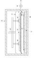
- the transparent surface material 10 and the support surface material 36 to which the protective film 16 is attached are carried into the decompression device 38.
- the protective film 16 is attached to the support surface material 36 by bonding the protective film 16 supplied as a roll-shaped roll to the support surface material 36 using a rubber roll or the like. At this time, a rubber roll can be pressed against the support surface material 36 or bonded in a reduced pressure space so that no gap is generated between the support surface material 36 and the adhesive surface of the protective film 16. It is preferable to use the protective film 16 that is slightly larger than the support surface material 36 so that the end of the protective film 16 can be easily gripped when peeled from the adhesive layer 14.
- An upper surface plate 42 having a plurality of suction pads 40 is disposed in the upper portion of the decompression device 38, and a lower surface plate 44 is disposed in the lower portion.
- the upper surface plate 42 can be moved in the vertical direction by an air cylinder 46.
- the support surface material 36 is attached to the suction pad 40 with the surface to which the protective film 16 is attached facing down.
- the transparent face material 10 is fixed on the lower surface plate 44 with the surface to which the first composition 26 is supplied facing up. In this way, the first composition 26 on the transparent face material 10 and the protective film 16 on the surface of the support face material 36 are opposed to each other without being in contact with each other.
- the support surface material 36 is a transparent surface material such as a glass plate or a resin plate.
- the thickness of the glass plate used as the support surface material 36 is preferably 0.5 to 10 mm, particularly preferably 1.0 to 5.0 mm. If the thickness of the glass plate is equal to or greater than the lower limit, the support surface material 36 is unlikely to warp or bend. If the thickness of the glass plate is equal to or less than the upper limit value, the mass of the support surface material 36 is not unnecessarily increased, and the support surface material 36 is not easily displaced when the precursor laminate before curing of the adhesive layer 14 is moved.
- the reduced-pressure atmosphere is preferably 1 kPa or less, more preferably 10 to 100 Pa, and further preferably 15 to 40 Pa.
- each component curable compound, photopolymerization initiator, polymerization inhibitor, chain transfer agent, light stabilizer, etc. contained in the first composition is difficult to vaporize.
- the time required to achieve the reduced pressure atmosphere is shortened.
- the transparent surface material 10 waiting below is held in a state where the support surface material 36 is adsorbed and held by the adsorption pad 40 of the upper surface plate 42. Then, the air cylinder 46 is moved downward. Then, the transparent surface material 10 and the support surface material 36 to which the protective film 16 is adhered are overlapped via the uncured weir-shaped portion 20A, and the transparent surface material 10, the protective film 16, and the uncured weir.
- the precursor layered body in which the uncured layered part made of the first composition 26 is sealed by the shaped part 20A is configured, and the precursor layered body is held for a predetermined time in a reduced pressure atmosphere. In the precursor laminate, the first composition 26 is expanded by the weight of the support surface material 36, the pressure from the moving support mechanism, and the like, and the space is filled with the first composition 26. Is formed.
- the time from when the transparent face material 10 and the support face material 36 are overlapped to the time when the reduced pressure atmosphere is released is not particularly limited, and the reduced pressure atmosphere may be released immediately after sealing the first composition 26, After sealing the first composition 26, the reduced pressure state may be maintained for a predetermined time.
- the first composition flows in the sealed space, the distance between the transparent surface material 10 and the protective film 16 attached to the support surface material 36 becomes uniform, and the atmospheric pressure Even if it raises, it becomes easy to maintain a sealed state.
- the time for maintaining the reduced pressure state may be several hours or longer, but is preferably within 1 hour, more preferably within 10 minutes from the viewpoint of production efficiency.
- the thickness can be relatively thick, 0.03 to 2 mm.
- step (c) the reduced pressure atmosphere is released, and the precursor laminate is placed in a higher pressure atmosphere than in step (c).
- the precursor laminate is taken out from the decompression device 38.
- the transparent face material 10 and the support face material 36 are pressed in a direction in close contact with the increased pressure. For this reason, even if a void exists in the sealed space in the precursor laminate, the uncured layered portion flows in the void, and the entire sealed space is uniformly filled with the uncured layered portion.
- the pressure atmosphere in step (d) may be an atmospheric pressure atmosphere or a higher pressure.
- the pressure atmosphere in the step (d) is preferably 80 to 120 kPa.
- the pressure atmosphere in the step (d) is most preferably an atmospheric pressure atmosphere because operations such as curing of the layered portion 18 can be performed without requiring special equipment.
- the time from when the precursor laminate is placed in a higher pressure atmosphere than in step (c) to the start of curing of the uncured layered portion is not particularly limited. .
- the time required for the process becomes the high pressure holding time. Therefore, if there is no void in the sealed space of the precursor laminate already when placed in an atmospheric pressure atmosphere, or if the void disappears during the process, the uncured layered part is immediately cured. Can do.
- the precursor laminate is held in an atmosphere at a higher pressure than in step (c) until the voids disappear.
- the high-pressure holding time may be a long time of one day or longer, but is preferably within 6 hours from the viewpoint of production efficiency, more preferably within 1 hour, and particularly within 10 minutes from the viewpoint of further increasing production efficiency. preferable.
- the uncured weir-like portion 20A and the layered portion inside the precursor laminate are cured to form the adhesive layer 14 having the layered portion 18 and the layered portion 20.
- the uncured weir 20A may be cured at the same time as the uncured layer is cured, or the uncured weir 20A may be cured before the uncured layer is cured.
- the uncured layered portion and the uncured weir-shaped portion 20A are made of a photocurable resin composition, light (from the support surface material 36 side to the uncured weir-shaped portion 20A and the uncured layered portion is light ( UV light and short wavelength visible light) to cure.
- the layered portion 18 and the weir-shaped portion 20 are cured by irradiating ultraviolet light or short wavelength visible light from a light source (ultraviolet lamp, high pressure mercury lamp, UV-LED, etc.).
- a light source ultraviolet light or visible light of 450 nm or less is preferable.
- the light shielding printing part is formed in the peripheral part of the transparent surface material, or when the antireflection layer is provided in the transparent surface material, light is irradiated from the support surface material side.
- the layered portion 18 When the layered portion 18 is made of a photocurable first composition and when a suitable shear elastic modulus cannot be obtained by sufficient photocuring, light irradiation is interrupted during curing, and the surface material to be bonded ( After bonding with a display panel or the like), the layered portion 18 may be irradiated with light again or heated to accelerate the curing of the layered portion 18. When curing is accelerated by heating, a small amount of a thermal polymerization initiator may be included in the photocurable first composition. Moreover, even if it is a case where a thermal polymerization initiator is not used together, the hardening state of the layer part 18 can be stabilized by heat-holding after incomplete photocuring, and it is preferable. If the first composition and the second composition are photocurable, the transparent surface material 1 with an adhesive layer can be produced at a low temperature that the film can withstand, which is advantageous in terms of protecting the protective film.
- the support surface material 36 is peeled from the protective film 16. Thereby, the transparent surface material 1 with the adhesion layer with the protective film 16 is obtained.
- the adhesive layer may be cooled. By cooling the pressure-sensitive adhesive layer, deformation of the pressure-sensitive adhesive layer when peeling the protective film can be suppressed, increasing the uniformity of the thickness of the pressure-sensitive adhesive layer after peeling the protective film, and bonding with the display panel The generation of voids can also be suppressed.
- the temperature at which the adhesive layer is cooled varies depending on the glass transition temperature of the resin used as the adhesive layer. It is preferable to set the temperature or lower.
- the lower limit temperature is not particularly defined, but is preferably ⁇ 30 ° C. or higher because some resins used for the protective film may become brittle at low temperatures and tear the film during peeling.
- the cooling time is preferably 5 minutes, but can be adjusted depending on the ease of peeling.
- the transparent surface material 1 with an adhesive layer of the present embodiment can be produced without any problem by the same production method as that of the first embodiment.
- the layered portion 18 and the weir-shaped portion 21 constituting the pressure-sensitive adhesive layer 14 may include the non-curing component, and both may be included.
- the difference between the non-curing component (W1) contained in the layered portion 18 and the non-curing component (W2) contained in the weir-like portion 21 is 40 or less.
- the laminate of the present invention is a laminate in which the transparent surface material with an adhesive layer of the present invention (one having no protective film) and the surface material to be bonded are bonded.
- the transparent surface material with an adhesive layer and a to-be-bonded surface material are bonded so that the adhesive layer of a transparent surface material with an adhesive layer may contact with a to-be-bonded surface material.
- the photocurable resin composition can be cured from the transparent face material side.
- the surface material to be bonded may be transparent or opaque.
- a display device is preferred as the laminate of the present invention.
- FIG. 12 is a cross-sectional view illustrating an example of a display device.
- the display device 2 includes a display panel 50 that is a surface material to be bonded, and a transparent surface material 1 with an adhesive layer that is bonded to the display panel 50 so that the adhesive layer 14 is in contact with the display panel 50 (does not have a protective film). And a flexible printed wiring board 60 (FPC) on which a driving IC for operating the display panel 50 connected to the display panel 50 is mounted.
- the display device 2 includes the transparent surface material 10, the display panel 50, and the adhesive layer 14 sandwiched between the transparent surface material 10 and the display panel 50.
- the surface material 50 to be bonded in the illustrated example is a display panel, and a transparent substrate 52 provided with a color filter and a transparent substrate 54 provided with a TFT (thin film transistor) are bonded via a liquid crystal layer 56, and a pair thereof is bonded.
- a liquid crystal panel having a configuration sandwiched between polarizing plates 58.
- the surface material to be bonded is a display panel, but the surface material to be bonded is not limited to the display panel, and may be a touch panel, for example.
- a display device manufacturing method will be described as an example of the laminate manufacturing method of the present invention.
- a display panel and a transparent surface with an adhesive layer are stacked in a reduced pressure atmosphere of 10 kPa or less so that the adhesive layer is in contact with the display panel. It is a method of pasting.
- the surface of the adhesive layer is covered with a protective film as in the transparent surface material 1 with the adhesive layer shown in FIG. 1, after the protective film is peeled off, the display panel and the transparent surface material with the adhesive layer are bonded.
- the pressure-reduced atmosphere when the display panel and the transparent surface material with the adhesive layer are bonded is 10 kPa or less, preferably 1 to 100 Pa, and more preferably 5 to 50 Pa.
- a step of obtaining a precursor laminate in which is sealed (I) In a state where the precursor laminate is placed under a higher pressure atmosphere than in the step (h), the uncured layer portion and the uncured weir portion are cured, and the layer portion 18 and the weir portion 20 are The process of forming the adhesion layer 14 which has.
- Step (f) The step (f) can be performed in the same manner as in the step (a) except that the display panel 50 is used instead of the transparent surface material 10 (protective plate) in the step (a).
- Step (g) The step (g) can be performed in the same manner as the step (b).
- Step (h) The step (h) can be performed in the same manner as the step (c) except that the transparent face material 10 (protective plate) is used instead of the support face material 36 to which the protective film 16 is bonded in the step (c).
- Step (i) can be performed in the same manner as in step (d).
- the flexible printed wiring board 60 (FPC) may be connected before the step (a) or after the step (a).
- a transparent plate made of soda lime glass having a length of 100 mm, a width of 100 mm, and a thickness of 3 mm On one side of a transparent plate made of soda lime glass having a length of 100 mm, a width of 100 mm, and a thickness of 3 mm, a protective film of 130 mm in length, 130 mm in width, and 0.75 mm in thickness (manufactured by Tosero, Puretect VLH-9) A support surface material-ii having a protective film attached thereto was prepared by attaching using a rubber roll so that the adhesive surface of the protective film was in contact with the glass.
- a polarizing plate with an adhesive layer (Polatechno Co., Ltd., KN-18240T) is attached to one surface of soda lime glass having a length of 100 mm, a width of 100 mm, and a thickness of 1.7 mm.
- a to-be-bonded surface material-iii that substitutes the display panel was used.
- the number of curable functional groups of the oligomer (A-1) was 2, the number average molecular weight was about 24,000, and the viscosity at 25 ° C. was about 830 Pa ⁇ s.
- 40 parts by mass of oligomer (A-1), 30 parts by mass of 2-hydroxybutyl methacrylate (manufactured by Kyoeisha Chemical Co., Ltd., light ester HOB), and 30 parts by mass of n-dodecyl methacrylate were mixed uniformly, To 100 parts by mass of the mixture, 0.3 part by mass of bis (2,4,6-trimethylbenzoyl) -phenylphosphine oxide (photopolymerization initiator, manufactured by Ciba Specialty Chemicals, IRGACURE 819), and 2, 0.04 part by mass of 5-di-tert-butylhydroquinone (polymerization inhibitor, manufactured by Tokyo Chemical Industry Co., Ltd.), 0.3 part by mass of UV absorber (manufactured by Ci
- a base composition -iv. 40 parts by mass of the oligomer (A-1), 40 parts by mass of 2-hydroxybutyl methacrylate (manufactured by Kyoeisha Chemical Co., Ltd., light ester HOB) and 20 parts by mass of n-dodecyl methacrylate were mixed uniformly.
- the base composition-iv or the base composition-v and the non-curable oligomer (II-i) are uniformly dissolved in the proportions shown in Table 1, and the decompression device is opened in the container.
- the defoaming treatment was performed by depressurizing the interior of the decompression device to about 20 Pa and holding it for 10 minutes to obtain a first composition-1 and a first composition-2.
- the non-curable oligomer (II-i) the same bifunctional polypropylene glycol having a molecular terminal modified with ethylene oxide (number average molecular weight calculated from the hydroxyl value: the same as that used in the synthesis of the oligomer (A-1) 4000) was used.
- the prepolymer 2-hydroxyethyl acrylate was added at a molar ratio of 1: 2, reacted at 70 ° C., and diluted with 30% by mass of isobornyl acrylate, urethane acrylate oligomer (A′-2) (hereinafter referred to as “the prepolymer”) And “Oligomer (A′-2)”).
- the number of curable functional groups of the oligomer (A′-2) was 2, the number average molecular weight was 55000, and the viscosity at 60 ° C. was 580 Pa ⁇ s.
- the base composition-vi or the base composition-vii is placed in a container in an open state while being placed in a container, and the pressure reduction apparatus is depressurized to about 20 Pa and held for 10 minutes to perform defoaming treatment.
- a second composition-1 was obtained.
- the base composition-v or the base composition-vii and the non-curable oligomer (II′-i) are uniformly dissolved in the proportions shown in Table 1, and are kept open in the decompression apparatus while being put in the container.
- the defoaming treatment was performed by reducing the pressure in the decompression device to about 20 Pa and holding for 10 minutes to obtain second composition-2 to second composition-7.
- the non-curable oligomer (II′-i) the same non-curable oligomer (II-i) was used.
- Example 1 (Process (a)) The second composition-1 was applied with a dispenser over the entire circumference at a position of about 7 mm from the inner edge of the light-shielding printing portion of the transparent face material-i so that the width was about 1 mm and the coating thickness was about 0.6 mm. A curing weir was formed. Next, UV light from a chemical lamp (manufactured by NEC, FL15BL, peak wavelength: 365 nm, irradiation intensity: 2 mW / cm 2 ) and visible light of 450 nm or less were formed on the transparent surface material-i for 30 seconds. The weir-shaped portion was irradiated uniformly. This thickened the uncured weir.
- a chemical lamp manufactured by NEC, FL15BL, peak wavelength: 365 nm, irradiation intensity: 2 mW / cm 2
- the first composition-1 was supplied to a plurality of locations in a region inside the uncured weir-like portion formed on the transparent face material-i using a dispenser so that the total mass became 2.5 g. During the supply of the first composition-1, there was no breakage such as breakage, and the shape of the uncured weir was maintained.
- the upper and lower surface plates are brought close to each other by the lifting device in the decompression device, and the transparent surface material-i and the support surface material-ii to which the protective film is adhered are pressured at 2 kPa through the first composition-1. And pressed for 10 seconds. Static electricity is removed from the electrostatic chuck, the supporting surface material ii is separated from the upper surface plate, and the pressure reducing device is returned to the atmospheric pressure atmosphere in about 15 seconds. With the transparent surface material i, the protective film, and the uncured weir A precursor laminate-1 in which the uncured layered portion of the first composition-1 was sealed was obtained. In the precursor laminate-1, the shape of the uncured weir-like portion was maintained in an almost initial state.
- Examples 2 to 6, Comparative Example 1 Transparent surface material with adhesive layer-2 to transparent surface material with adhesive layer-7 were obtained in the same manner as in Example 1 except that the types of the first composition and the second composition were changed as shown in Table 2. .
- Step evaluation (1) Acceleration test The protective film was peeled off from the transparent surface material with an adhesive layer obtained in each example, and stored in a thermostatic bath at 80 ° C for 5 days.
- (2) Shape Evaluation of Adhesive Layer For the shape evaluation of the adhesive layer, a digital microscope VHX-1000 manufactured by Keyence Corporation was used, and the shape was measured using the depth of focus. The measurement location was a part extending over a distance of about 5 mm on the adhesive layer surface extending from the outer peripheral edge of the weir-like portion at the center of one side of the adhesive layer on the transparent surface material-i to the layered portion. In the measurement, a silver paste was thinly applied to the surface of the adhesive layer for the purpose of improving measurement sensitivity.
- the measurement was performed before and after the acceleration test (1).
- the step between the weir-like part and the layer-like part before and after the acceleration test was evaluated.
- the difference in height between the highest point and the lowest point in the measurement location was calculated as a step.
- the transparent surface material with an adhesive layer from which the protective film has been peeled off is placed on the lower surface plate in the decompression device in which a pair of surface plate lifting devices are installed. It was placed flat so that the surface of the adhesive layer was on top.
- the surface material to be bonded-iii was held on the lower surface of the upper surface plate of the lifting device in the decompression device using an electrostatic chuck so that the distance from the transparent surface material with adhesive layer-1 was 10 mm.
- the decompression device was sealed and evacuated until the pressure in the decompression device reached about 30 Pa.
- the upper and lower surface plates are brought close to each other by an elevating device in the decompression device, and the surface material to be bonded -iii and the transparent surface material with adhesive layer-1 are pressure-bonded through the adhesive layer at a pressure of 2 kPa and held for 10 seconds. It was. Static electricity is removed from the electrostatic chuck, the surface material to be bonded -iii is separated from the upper platen, and the pressure reducing device is returned to atmospheric pressure in about 20 seconds, and adhesion is made between the transparent surface material -i and the surface material to be bonded -iii. A layered product-1 in which the layers were sandwiched was obtained.
- Laminate-1 When the laminate-1 was observed immediately after lamination, many fine voids (bubbles) were observed at the interface between the surface material to be bonded-iii and the adhesive layer of the transparent surface material with adhesive layer-1. Laminate-1 was allowed to stand, and the time until voids disappeared (void disappearance time) was measured. Laminates-2 to -7 were obtained in the same manner using the transparent face materials with adhesive layer-2 to -7, and the void disappearance time was measured. The results are shown in Table 1. The void disappearance time was the average of the results of two samples.
- Example 7 [Transparent surface material] Soda lime glass having a length of 250 mm, a width of 190 mm, and a thickness of 1.3 mm was used as a transparent surface material. In this example, in order to make it easy to confirm the influence of display unevenness, a glass substrate on which no light-shielding print portion is formed is used as a transparent surface material.
- a transparent plate made of soda lime glass having a length of 100 mm, a width of 100 mm, and a thickness of 3 mm On one side of a transparent plate made of soda lime glass having a length of 100 mm, a width of 100 mm, and a thickness of 3 mm, a protective film of 130 mm in length, 130 mm in width, and 0.75 mm in thickness (manufactured by Tosero, Puretect VLH-9) A support surface material to which the protective film was attached was prepared by sticking using a rubber roll so that the adhesive surface of the protective film was in contact with the glass.
- the base composition vi was used as the third resin composition.
- the storage shear modulus of the resin layer obtained by curing the first to third resin compositions is determined using a rheometer (Physica MCR301, manufactured by Anton Paar).
- the resin composition was sandwiched between a soda lime glass stage and a measuring spindle (D-PP20 / AL / S07, manufactured by Anton Paar), and a black light (35 ° C. under a nitrogen atmosphere)
- a photo-curable resin composition for resin layer formation was cured by applying a 1% dynamic shear strain while irradiating with light of 2 mW / cm 2 for 10 minutes by FL15BL (manufactured by NEC Corporation).
- the storage shear modulus of the resin layer obtained from each resin composition is shown in Table 3 below.
- a second resin composition is applied with a dispenser over the entire circumference at a position of about 25 mm from the outer peripheral edge of the transparent surface material so as to have a width of about 1 mm and a coating thickness of about 0.6 mm, and an LED light source associated with the dispenser. Then, UV light was irradiated to form a partially cured weir-shaped portion (see FIGS. 4 to 5).
- the first resin composition was supplied to a plurality of locations in a region inside the weir-shaped portion using a dispenser so that the total mass was 2.5 g. During the supply of the first resin composition, there was no breakage such as breakage, and the shape of the uncured weir was maintained.
- the surface coated with the first resin composition is placed on the lower surface plate in the decompression device (see FIG. 6) in which the lifting device for the pair of surface plates is installed. And evacuated until the pressure in the decompression device reached about 40 Pa.
- the upper and lower surface plates are brought close to each other by an elevating device in the depressurization apparatus, and the transparent surface material and the support surface material to which the protective film is attached are pressure-bonded through the first resin composition at a pressure of 2 kPa. And held for 10 seconds for bonding.
- the inside of the decompression device was returned to the atmospheric pressure atmosphere to obtain a precursor laminate in which the first resin composition was sealed with a transparent surface material, a protective film, and a weir-shaped portion.
- the precursor laminate is uniformly irradiated with UV light from a chemical lamp (NEC Corporation, FL15BL, peak wavelength: 365 nm, irradiation intensity: 2 mW / cm 2 ) and visible light of 450 nm or less from the support surface material side for 10 minutes.
- a chemical lamp NEC Corporation, FL15BL, peak wavelength: 365 nm, irradiation intensity: 2 mW / cm 2
- visible light 450 nm or less from the support surface material side for 10 minutes.
- the adhesion layer was formed by hardening a weir-like part (2nd resin composition) and a 1st resin composition. Irradiation intensity was measured using an illuminometer (manufactured by USHIO INC., UV intensity meter unimeter UIT-101). The thickness of the layered portion after curing was approximately uniform at 0.4 mm.
- the support surface material was peeled off from the protective film to produce a transparent surface material with an adhesive layer on which the protective film was stuck.
- Example 7 in which the ratio of the elastic modulus between the layered portion and the weir-shaped portion was the lowest, display unevenness was not visible. It was confirmed that good visibility could be maintained by keeping the ratio of elastic modulus between the layered portion and the weir-shaped portion low.
Landscapes
- Chemical & Material Sciences (AREA)
- Organic Chemistry (AREA)
- Chemical Kinetics & Catalysis (AREA)
- Health & Medical Sciences (AREA)
- Medicinal Chemistry (AREA)
- Polymers & Plastics (AREA)
- Laminated Bodies (AREA)
- Adhesives Or Adhesive Processes (AREA)
- Adhesive Tapes (AREA)
- Devices For Indicating Variable Information By Combining Individual Elements (AREA)
Abstract
L'invention concerne une plaque de face transparente (1) comprenant une couche adhésive, qui est caractérisée en ce qu'elle comprend une plaque de face transparente (10) et une couche adhésive (14) qui est formée sur la surface de la plaque de face transparente (10) et une partie sous forme de couche (18) et une partie sous forme de barrage (20), et qui est également caractérisée en ce que la différence entre la teneur (W1) en un oligomère non durcissable (II) dans la partie sous forme de couche (18), ladite teneur (W1) étant exprimée en pourcentage en masse, et la teneur (W2) en un oligomère non durcissable (II') dans la partie sous forme de barrage (20), ladite teneur (W2) étant exprimée en pourcentage en masse, à savoir (W2) - (W1), est définie de manière à être inférieure ou égale à 40. L'invention comprend un dispositif d'affichage qui comprend un panneau d'affichage et une plaque de face transparente (1) comprenant une couche adhésive, ladite plaque de face transparente (1) étant liée au panneau d'affichage de sorte que la couche adhésive soit en contact avec le panneau d'affichage.
Priority Applications (2)
| Application Number | Priority Date | Filing Date | Title |
|---|---|---|---|
| JP2014554566A JPWO2014104231A1 (ja) | 2012-12-28 | 2013-12-26 | 粘着層付き透明面材、積層体、表示装置、およびそれらの製造方法 |
| CN201380067251.5A CN104936778A (zh) | 2012-12-28 | 2013-12-26 | 带粘合层的透明面材、层叠体、显示装置及它们的制造方法 |
Applications Claiming Priority (4)
| Application Number | Priority Date | Filing Date | Title |
|---|---|---|---|
| JP2012288004 | 2012-12-28 | ||
| JP2012-288004 | 2012-12-28 | ||
| JP2013-037505 | 2013-02-27 | ||
| JP2013037505 | 2013-02-27 |
Publications (1)
| Publication Number | Publication Date |
|---|---|
| WO2014104231A1 true WO2014104231A1 (fr) | 2014-07-03 |
Family
ID=51021305
Family Applications (1)
| Application Number | Title | Priority Date | Filing Date |
|---|---|---|---|
| PCT/JP2013/084968 Ceased WO2014104231A1 (fr) | 2012-12-28 | 2013-12-26 | Plaque de face transparente comprenant une couche adhésive, stratifié, dispositif d'affichage et procédés de production associés |
Country Status (4)
| Country | Link |
|---|---|
| JP (1) | JPWO2014104231A1 (fr) |
| CN (1) | CN104936778A (fr) |
| TW (1) | TW201431700A (fr) |
| WO (1) | WO2014104231A1 (fr) |
Cited By (6)
| Publication number | Priority date | Publication date | Assignee | Title |
|---|---|---|---|---|
| JP2016017119A (ja) * | 2014-07-07 | 2016-02-01 | 旭硝子株式会社 | 両面粘着フィルム、粘着層付き透明面材、および積層体 |
| JP2016204496A (ja) * | 2015-04-21 | 2016-12-08 | 旭硝子株式会社 | 両面粘着シートの製造方法、両面粘着シート付き透明面材の製造方法、表示装置の製造方法 |
| JP2017105940A (ja) * | 2015-12-10 | 2017-06-15 | 日立化成株式会社 | 粘着剤、及び粘着シート |
| JP2017128736A (ja) * | 2015-11-26 | 2017-07-27 | バンドー化学株式会社 | 光学透明粘着シート、光学透明粘着シートの製造方法、積層体、及び、タッチパネル付き表示装置 |
| EP3674784A4 (fr) * | 2017-08-25 | 2020-07-01 | Panasonic Intellectual Property Management Co., Ltd. | Dispositif de fabrication et procédé de fabrication de dispositif d'affichage, et dispositif d'affichage |
| KR20220042222A (ko) * | 2019-09-17 | 2022-04-04 | 데쿠세리아루즈 가부시키가이샤 | 댐 형성 방법 및 적층체의 제조 방법 |
Families Citing this family (2)
| Publication number | Priority date | Publication date | Assignee | Title |
|---|---|---|---|---|
| WO2019151265A1 (fr) * | 2018-02-01 | 2019-08-08 | Agc株式会社 | Matériau de base et copolymère |
| KR20240039658A (ko) * | 2022-09-19 | 2024-03-27 | 삼성디스플레이 주식회사 | 합착 장치 및 이를 이용한 표시 장치의 제조 방법 |
Citations (5)
| Publication number | Priority date | Publication date | Assignee | Title |
|---|---|---|---|---|
| JP2009046620A (ja) * | 2007-08-22 | 2009-03-05 | Mitsubishi Plastics Inc | 粘着シート |
| JP2009091434A (ja) * | 2007-10-05 | 2009-04-30 | Sekisui Chem Co Ltd | 中間膜用重合性組成物、中間膜及び透明積層体 |
| WO2011158839A1 (fr) * | 2010-06-16 | 2011-12-22 | 旭硝子株式会社 | Composition de résine durcissable, stratifié la comprenant, et procédé de production du stratifié |
| WO2011158840A1 (fr) * | 2010-06-16 | 2011-12-22 | 旭硝子株式会社 | Composition de résine durcissable, stratifié la comprenant, et procédé de production du stratifié |
| WO2012077726A1 (fr) * | 2010-12-08 | 2012-06-14 | 旭硝子株式会社 | Matériau de surface transparent doté d'une couche d'adhésif, dispositif d'affichage et procédés de production associés |
Family Cites Families (2)
| Publication number | Priority date | Publication date | Assignee | Title |
|---|---|---|---|---|
| JP5068793B2 (ja) * | 2009-09-24 | 2012-11-07 | リンテック株式会社 | 粘着シート |
| TW201122055A (en) * | 2009-10-30 | 2011-07-01 | Asahi Glass Co Ltd | Curable resin composition for sealing portion formation, laminate, and production method therefor |
-
2013
- 2013-12-26 JP JP2014554566A patent/JPWO2014104231A1/ja active Pending
- 2013-12-26 CN CN201380067251.5A patent/CN104936778A/zh active Pending
- 2013-12-26 WO PCT/JP2013/084968 patent/WO2014104231A1/fr not_active Ceased
- 2013-12-27 TW TW102148697A patent/TW201431700A/zh unknown
Patent Citations (5)
| Publication number | Priority date | Publication date | Assignee | Title |
|---|---|---|---|---|
| JP2009046620A (ja) * | 2007-08-22 | 2009-03-05 | Mitsubishi Plastics Inc | 粘着シート |
| JP2009091434A (ja) * | 2007-10-05 | 2009-04-30 | Sekisui Chem Co Ltd | 中間膜用重合性組成物、中間膜及び透明積層体 |
| WO2011158839A1 (fr) * | 2010-06-16 | 2011-12-22 | 旭硝子株式会社 | Composition de résine durcissable, stratifié la comprenant, et procédé de production du stratifié |
| WO2011158840A1 (fr) * | 2010-06-16 | 2011-12-22 | 旭硝子株式会社 | Composition de résine durcissable, stratifié la comprenant, et procédé de production du stratifié |
| WO2012077726A1 (fr) * | 2010-12-08 | 2012-06-14 | 旭硝子株式会社 | Matériau de surface transparent doté d'une couche d'adhésif, dispositif d'affichage et procédés de production associés |
Cited By (9)
| Publication number | Priority date | Publication date | Assignee | Title |
|---|---|---|---|---|
| JP2016017119A (ja) * | 2014-07-07 | 2016-02-01 | 旭硝子株式会社 | 両面粘着フィルム、粘着層付き透明面材、および積層体 |
| JP2016204496A (ja) * | 2015-04-21 | 2016-12-08 | 旭硝子株式会社 | 両面粘着シートの製造方法、両面粘着シート付き透明面材の製造方法、表示装置の製造方法 |
| JP2017128736A (ja) * | 2015-11-26 | 2017-07-27 | バンドー化学株式会社 | 光学透明粘着シート、光学透明粘着シートの製造方法、積層体、及び、タッチパネル付き表示装置 |
| JP2017105940A (ja) * | 2015-12-10 | 2017-06-15 | 日立化成株式会社 | 粘着剤、及び粘着シート |
| EP3674784A4 (fr) * | 2017-08-25 | 2020-07-01 | Panasonic Intellectual Property Management Co., Ltd. | Dispositif de fabrication et procédé de fabrication de dispositif d'affichage, et dispositif d'affichage |
| US11755065B2 (en) | 2017-08-25 | 2023-09-12 | Panasonic Intellectual Property Management Co., Ltd. | Display manufacturing device and manufacturing method, and display |
| KR20220042222A (ko) * | 2019-09-17 | 2022-04-04 | 데쿠세리아루즈 가부시키가이샤 | 댐 형성 방법 및 적층체의 제조 방법 |
| US12441095B2 (en) | 2019-09-17 | 2025-10-14 | Dexerials Corporation | Dam forming method and method for manufacturing laminate |
| KR102924236B1 (ko) * | 2019-09-17 | 2026-02-09 | 데쿠세리아루즈 가부시키가이샤 | 댐 형성 방법 및 적층체의 제조 방법 |
Also Published As
| Publication number | Publication date |
|---|---|
| JPWO2014104231A1 (ja) | 2017-01-19 |
| TW201431700A (zh) | 2014-08-16 |
| CN104936778A (zh) | 2015-09-23 |
Similar Documents
| Publication | Publication Date | Title |
|---|---|---|
| JP5811143B2 (ja) | 表示装置 | |
| JP5811142B2 (ja) | 表示装置 | |
| JP5867571B2 (ja) | 樹脂層および表示装置 | |
| JP5729385B2 (ja) | 硬化性樹脂組成物およびこれを用いた積層体の製造方法 | |
| JP5757288B2 (ja) | 粘着層付き透明面材、表示装置およびそれらの製造方法 | |
| JP2014139297A (ja) | 粘着層付き透明面材、表示装置およびそれらの製造方法 | |
| WO2014104231A1 (fr) | Plaque de face transparente comprenant une couche adhésive, stratifié, dispositif d'affichage et procédés de production associés | |
| WO2015159957A1 (fr) | Matériau de feuille transparent doté d'une couche adhésive sensible à la pression, dispositif d'affichage, leurs procédés de production et feuille adhésive sensible à la pression | |
| JP6024505B2 (ja) | 硬化性樹脂組成物、粘着層付き透明面材および積層体 |
Legal Events
| Date | Code | Title | Description |
|---|---|---|---|
| 121 | Ep: the epo has been informed by wipo that ep was designated in this application |
Ref document number: 13869198 Country of ref document: EP Kind code of ref document: A1 |
|
| ENP | Entry into the national phase |
Ref document number: 2014554566 Country of ref document: JP Kind code of ref document: A |
|
| NENP | Non-entry into the national phase |
Ref country code: DE |
|
| 122 | Ep: pct application non-entry in european phase |
Ref document number: 13869198 Country of ref document: EP Kind code of ref document: A1 |