WO2014104394A1 - 方向性電磁鋼板の製造方法および方向性電磁鋼板製造用の一次再結晶鋼板 - Google Patents
方向性電磁鋼板の製造方法および方向性電磁鋼板製造用の一次再結晶鋼板 Download PDFInfo
- Publication number
- WO2014104394A1 WO2014104394A1 PCT/JP2013/085322 JP2013085322W WO2014104394A1 WO 2014104394 A1 WO2014104394 A1 WO 2014104394A1 JP 2013085322 W JP2013085322 W JP 2013085322W WO 2014104394 A1 WO2014104394 A1 WO 2014104394A1
- Authority
- WO
- WIPO (PCT)
- Prior art keywords
- ppm
- sol
- less
- grain
- steel sheet
- Prior art date
- Legal status (The legal status is an assumption and is not a legal conclusion. Google has not performed a legal analysis and makes no representation as to the accuracy of the status listed.)
- Ceased
Links
Images


Classifications
-
- H—ELECTRICITY
- H01—ELECTRIC ELEMENTS
- H01F—MAGNETS; INDUCTANCES; TRANSFORMERS; SELECTION OF MATERIALS FOR THEIR MAGNETIC PROPERTIES
- H01F1/00—Magnets or magnetic bodies characterised by the magnetic materials therefor; Selection of materials for their magnetic properties
- H01F1/01—Magnets or magnetic bodies characterised by the magnetic materials therefor; Selection of materials for their magnetic properties of inorganic materials
- H01F1/03—Magnets or magnetic bodies characterised by the magnetic materials therefor; Selection of materials for their magnetic properties of inorganic materials characterised by their coercivity
- H01F1/12—Magnets or magnetic bodies characterised by the magnetic materials therefor; Selection of materials for their magnetic properties of inorganic materials characterised by their coercivity of soft-magnetic materials
- H01F1/14—Magnets or magnetic bodies characterised by the magnetic materials therefor; Selection of materials for their magnetic properties of inorganic materials characterised by their coercivity of soft-magnetic materials metals or alloys
- H01F1/147—Alloys characterised by their composition
- H01F1/14766—Fe-Si based alloys
- H01F1/14775—Fe-Si based alloys in the form of sheets
- H01F1/14783—Fe-Si based alloys in the form of sheets with insulating coating
-
- C—CHEMISTRY; METALLURGY
- C21—METALLURGY OF IRON
- C21D—MODIFYING THE PHYSICAL STRUCTURE OF FERROUS METALS; GENERAL DEVICES FOR HEAT TREATMENT OF FERROUS OR NON-FERROUS METALS OR ALLOYS; MAKING METAL MALLEABLE, e.g. BY DECARBURISATION OR TEMPERING
- C21D8/00—Modifying the physical properties of ferrous metals or ferrous alloys by deformation combined with, or followed by, heat treatment
- C21D8/12—Modifying the physical properties of ferrous metals or ferrous alloys by deformation combined with, or followed by, heat treatment during manufacturing of articles with special electromagnetic properties
-
- B—PERFORMING OPERATIONS; TRANSPORTING
- B21—MECHANICAL METAL-WORKING WITHOUT ESSENTIALLY REMOVING MATERIAL; PUNCHING METAL
- B21B—ROLLING OF METAL
- B21B3/00—Rolling materials of special alloys so far as the composition of the alloy requires or permits special rolling methods or sequences ; Rolling of aluminium, copper, zinc or other non-ferrous metals
-
- B—PERFORMING OPERATIONS; TRANSPORTING
- B21—MECHANICAL METAL-WORKING WITHOUT ESSENTIALLY REMOVING MATERIAL; PUNCHING METAL
- B21B—ROLLING OF METAL
- B21B45/00—Devices for surface or other treatment of work, specially combined with or arranged in, or specially adapted for use in connection with, metal-rolling mills
-
- C—CHEMISTRY; METALLURGY
- C21—METALLURGY OF IRON
- C21D—MODIFYING THE PHYSICAL STRUCTURE OF FERROUS METALS; GENERAL DEVICES FOR HEAT TREATMENT OF FERROUS OR NON-FERROUS METALS OR ALLOYS; MAKING METAL MALLEABLE, e.g. BY DECARBURISATION OR TEMPERING
- C21D6/00—Heat treatment of ferrous alloys
- C21D6/005—Heat treatment of ferrous alloys containing Mn
-
- C—CHEMISTRY; METALLURGY
- C21—METALLURGY OF IRON
- C21D—MODIFYING THE PHYSICAL STRUCTURE OF FERROUS METALS; GENERAL DEVICES FOR HEAT TREATMENT OF FERROUS OR NON-FERROUS METALS OR ALLOYS; MAKING METAL MALLEABLE, e.g. BY DECARBURISATION OR TEMPERING
- C21D6/00—Heat treatment of ferrous alloys
- C21D6/008—Heat treatment of ferrous alloys containing Si
-
- C—CHEMISTRY; METALLURGY
- C21—METALLURGY OF IRON
- C21D—MODIFYING THE PHYSICAL STRUCTURE OF FERROUS METALS; GENERAL DEVICES FOR HEAT TREATMENT OF FERROUS OR NON-FERROUS METALS OR ALLOYS; MAKING METAL MALLEABLE, e.g. BY DECARBURISATION OR TEMPERING
- C21D8/00—Modifying the physical properties of ferrous metals or ferrous alloys by deformation combined with, or followed by, heat treatment
- C21D8/12—Modifying the physical properties of ferrous metals or ferrous alloys by deformation combined with, or followed by, heat treatment during manufacturing of articles with special electromagnetic properties
- C21D8/1216—Modifying the physical properties of ferrous metals or ferrous alloys by deformation combined with, or followed by, heat treatment during manufacturing of articles with special electromagnetic properties characterised by the working steps
- C21D8/1222—Hot rolling
-
- C—CHEMISTRY; METALLURGY
- C21—METALLURGY OF IRON
- C21D—MODIFYING THE PHYSICAL STRUCTURE OF FERROUS METALS; GENERAL DEVICES FOR HEAT TREATMENT OF FERROUS OR NON-FERROUS METALS OR ALLOYS; MAKING METAL MALLEABLE, e.g. BY DECARBURISATION OR TEMPERING
- C21D8/00—Modifying the physical properties of ferrous metals or ferrous alloys by deformation combined with, or followed by, heat treatment
- C21D8/12—Modifying the physical properties of ferrous metals or ferrous alloys by deformation combined with, or followed by, heat treatment during manufacturing of articles with special electromagnetic properties
- C21D8/1216—Modifying the physical properties of ferrous metals or ferrous alloys by deformation combined with, or followed by, heat treatment during manufacturing of articles with special electromagnetic properties characterised by the working steps
- C21D8/1233—Cold rolling
-
- C—CHEMISTRY; METALLURGY
- C21—METALLURGY OF IRON
- C21D—MODIFYING THE PHYSICAL STRUCTURE OF FERROUS METALS; GENERAL DEVICES FOR HEAT TREATMENT OF FERROUS OR NON-FERROUS METALS OR ALLOYS; MAKING METAL MALLEABLE, e.g. BY DECARBURISATION OR TEMPERING
- C21D8/00—Modifying the physical properties of ferrous metals or ferrous alloys by deformation combined with, or followed by, heat treatment
- C21D8/12—Modifying the physical properties of ferrous metals or ferrous alloys by deformation combined with, or followed by, heat treatment during manufacturing of articles with special electromagnetic properties
- C21D8/1244—Modifying the physical properties of ferrous metals or ferrous alloys by deformation combined with, or followed by, heat treatment during manufacturing of articles with special electromagnetic properties characterised by the heat treatment
- C21D8/1255—Modifying the physical properties of ferrous metals or ferrous alloys by deformation combined with, or followed by, heat treatment during manufacturing of articles with special electromagnetic properties characterised by the heat treatment with diffusion of elements, e.g. decarburising, nitriding
-
- C—CHEMISTRY; METALLURGY
- C21—METALLURGY OF IRON
- C21D—MODIFYING THE PHYSICAL STRUCTURE OF FERROUS METALS; GENERAL DEVICES FOR HEAT TREATMENT OF FERROUS OR NON-FERROUS METALS OR ALLOYS; MAKING METAL MALLEABLE, e.g. BY DECARBURISATION OR TEMPERING
- C21D8/00—Modifying the physical properties of ferrous metals or ferrous alloys by deformation combined with, or followed by, heat treatment
- C21D8/12—Modifying the physical properties of ferrous metals or ferrous alloys by deformation combined with, or followed by, heat treatment during manufacturing of articles with special electromagnetic properties
- C21D8/1244—Modifying the physical properties of ferrous metals or ferrous alloys by deformation combined with, or followed by, heat treatment during manufacturing of articles with special electromagnetic properties characterised by the heat treatment
- C21D8/1261—Modifying the physical properties of ferrous metals or ferrous alloys by deformation combined with, or followed by, heat treatment during manufacturing of articles with special electromagnetic properties characterised by the heat treatment following hot rolling
-
- C—CHEMISTRY; METALLURGY
- C21—METALLURGY OF IRON
- C21D—MODIFYING THE PHYSICAL STRUCTURE OF FERROUS METALS; GENERAL DEVICES FOR HEAT TREATMENT OF FERROUS OR NON-FERROUS METALS OR ALLOYS; MAKING METAL MALLEABLE, e.g. BY DECARBURISATION OR TEMPERING
- C21D8/00—Modifying the physical properties of ferrous metals or ferrous alloys by deformation combined with, or followed by, heat treatment
- C21D8/12—Modifying the physical properties of ferrous metals or ferrous alloys by deformation combined with, or followed by, heat treatment during manufacturing of articles with special electromagnetic properties
- C21D8/1244—Modifying the physical properties of ferrous metals or ferrous alloys by deformation combined with, or followed by, heat treatment during manufacturing of articles with special electromagnetic properties characterised by the heat treatment
- C21D8/1272—Final recrystallisation annealing
-
- C—CHEMISTRY; METALLURGY
- C21—METALLURGY OF IRON
- C21D—MODIFYING THE PHYSICAL STRUCTURE OF FERROUS METALS; GENERAL DEVICES FOR HEAT TREATMENT OF FERROUS OR NON-FERROUS METALS OR ALLOYS; MAKING METAL MALLEABLE, e.g. BY DECARBURISATION OR TEMPERING
- C21D9/00—Heat treatment, e.g. annealing, hardening, quenching or tempering, adapted for particular articles; Furnaces therefor
- C21D9/46—Heat treatment, e.g. annealing, hardening, quenching or tempering, adapted for particular articles; Furnaces therefor for sheet metals
-
- C—CHEMISTRY; METALLURGY
- C22—METALLURGY; FERROUS OR NON-FERROUS ALLOYS; TREATMENT OF ALLOYS OR NON-FERROUS METALS
- C22C—ALLOYS
- C22C38/00—Ferrous alloys, e.g. steel alloys
- C22C38/001—Ferrous alloys, e.g. steel alloys containing N
-
- C—CHEMISTRY; METALLURGY
- C22—METALLURGY; FERROUS OR NON-FERROUS ALLOYS; TREATMENT OF ALLOYS OR NON-FERROUS METALS
- C22C—ALLOYS
- C22C38/00—Ferrous alloys, e.g. steel alloys
- C22C38/002—Ferrous alloys, e.g. steel alloys containing In, Mg, or other elements not provided for in one single group C22C38/001 - C22C38/60
-
- C—CHEMISTRY; METALLURGY
- C22—METALLURGY; FERROUS OR NON-FERROUS ALLOYS; TREATMENT OF ALLOYS OR NON-FERROUS METALS
- C22C—ALLOYS
- C22C38/00—Ferrous alloys, e.g. steel alloys
- C22C38/008—Ferrous alloys, e.g. steel alloys containing tin
-
- C—CHEMISTRY; METALLURGY
- C22—METALLURGY; FERROUS OR NON-FERROUS ALLOYS; TREATMENT OF ALLOYS OR NON-FERROUS METALS
- C22C—ALLOYS
- C22C38/00—Ferrous alloys, e.g. steel alloys
- C22C38/02—Ferrous alloys, e.g. steel alloys containing silicon
-
- C—CHEMISTRY; METALLURGY
- C22—METALLURGY; FERROUS OR NON-FERROUS ALLOYS; TREATMENT OF ALLOYS OR NON-FERROUS METALS
- C22C—ALLOYS
- C22C38/00—Ferrous alloys, e.g. steel alloys
- C22C38/04—Ferrous alloys, e.g. steel alloys containing manganese
-
- C—CHEMISTRY; METALLURGY
- C22—METALLURGY; FERROUS OR NON-FERROUS ALLOYS; TREATMENT OF ALLOYS OR NON-FERROUS METALS
- C22C—ALLOYS
- C22C38/00—Ferrous alloys, e.g. steel alloys
- C22C38/06—Ferrous alloys, e.g. steel alloys containing aluminium
-
- C—CHEMISTRY; METALLURGY
- C22—METALLURGY; FERROUS OR NON-FERROUS ALLOYS; TREATMENT OF ALLOYS OR NON-FERROUS METALS
- C22C—ALLOYS
- C22C38/00—Ferrous alloys, e.g. steel alloys
- C22C38/08—Ferrous alloys, e.g. steel alloys containing nickel
-
- C—CHEMISTRY; METALLURGY
- C22—METALLURGY; FERROUS OR NON-FERROUS ALLOYS; TREATMENT OF ALLOYS OR NON-FERROUS METALS
- C22C—ALLOYS
- C22C38/00—Ferrous alloys, e.g. steel alloys
- C22C38/12—Ferrous alloys, e.g. steel alloys containing tungsten, tantalum, molybdenum, vanadium, or niobium
-
- C—CHEMISTRY; METALLURGY
- C22—METALLURGY; FERROUS OR NON-FERROUS ALLOYS; TREATMENT OF ALLOYS OR NON-FERROUS METALS
- C22C—ALLOYS
- C22C38/00—Ferrous alloys, e.g. steel alloys
- C22C38/16—Ferrous alloys, e.g. steel alloys containing copper
-
- C—CHEMISTRY; METALLURGY
- C22—METALLURGY; FERROUS OR NON-FERROUS ALLOYS; TREATMENT OF ALLOYS OR NON-FERROUS METALS
- C22C—ALLOYS
- C22C38/00—Ferrous alloys, e.g. steel alloys
- C22C38/18—Ferrous alloys, e.g. steel alloys containing chromium
- C22C38/22—Ferrous alloys, e.g. steel alloys containing chromium with molybdenum or tungsten
-
- C—CHEMISTRY; METALLURGY
- C22—METALLURGY; FERROUS OR NON-FERROUS ALLOYS; TREATMENT OF ALLOYS OR NON-FERROUS METALS
- C22C—ALLOYS
- C22C38/00—Ferrous alloys, e.g. steel alloys
- C22C38/60—Ferrous alloys, e.g. steel alloys containing lead, selenium, tellurium, or antimony, or more than 0.04% by weight of sulfur
-
- C—CHEMISTRY; METALLURGY
- C23—COATING METALLIC MATERIAL; COATING MATERIAL WITH METALLIC MATERIAL; CHEMICAL SURFACE TREATMENT; DIFFUSION TREATMENT OF METALLIC MATERIAL; COATING BY VACUUM EVAPORATION, BY SPUTTERING, BY ION IMPLANTATION OR BY CHEMICAL VAPOUR DEPOSITION, IN GENERAL; INHIBITING CORROSION OF METALLIC MATERIAL OR INCRUSTATION IN GENERAL
- C23C—COATING METALLIC MATERIAL; COATING MATERIAL WITH METALLIC MATERIAL; SURFACE TREATMENT OF METALLIC MATERIAL BY DIFFUSION INTO THE SURFACE, BY CHEMICAL CONVERSION OR SUBSTITUTION; COATING BY VACUUM EVAPORATION, BY SPUTTERING, BY ION IMPLANTATION OR BY CHEMICAL VAPOUR DEPOSITION, IN GENERAL
- C23C8/00—Solid state diffusion of only non-metal elements into metallic material surfaces; Chemical surface treatment of metallic material by reaction of the surface with a reactive gas, leaving reaction products of surface material in the coating, e.g. conversion coatings, passivation of metals
- C23C8/06—Solid state diffusion of only non-metal elements into metallic material surfaces; Chemical surface treatment of metallic material by reaction of the surface with a reactive gas, leaving reaction products of surface material in the coating, e.g. conversion coatings, passivation of metals using gases
- C23C8/08—Solid state diffusion of only non-metal elements into metallic material surfaces; Chemical surface treatment of metallic material by reaction of the surface with a reactive gas, leaving reaction products of surface material in the coating, e.g. conversion coatings, passivation of metals using gases only one element being applied
- C23C8/24—Nitriding
- C23C8/26—Nitriding of ferrous surfaces
-
- C—CHEMISTRY; METALLURGY
- C23—COATING METALLIC MATERIAL; COATING MATERIAL WITH METALLIC MATERIAL; CHEMICAL SURFACE TREATMENT; DIFFUSION TREATMENT OF METALLIC MATERIAL; COATING BY VACUUM EVAPORATION, BY SPUTTERING, BY ION IMPLANTATION OR BY CHEMICAL VAPOUR DEPOSITION, IN GENERAL; INHIBITING CORROSION OF METALLIC MATERIAL OR INCRUSTATION IN GENERAL
- C23C—COATING METALLIC MATERIAL; COATING MATERIAL WITH METALLIC MATERIAL; SURFACE TREATMENT OF METALLIC MATERIAL BY DIFFUSION INTO THE SURFACE, BY CHEMICAL CONVERSION OR SUBSTITUTION; COATING BY VACUUM EVAPORATION, BY SPUTTERING, BY ION IMPLANTATION OR BY CHEMICAL VAPOUR DEPOSITION, IN GENERAL
- C23C8/00—Solid state diffusion of only non-metal elements into metallic material surfaces; Chemical surface treatment of metallic material by reaction of the surface with a reactive gas, leaving reaction products of surface material in the coating, e.g. conversion coatings, passivation of metals
- C23C8/40—Solid state diffusion of only non-metal elements into metallic material surfaces; Chemical surface treatment of metallic material by reaction of the surface with a reactive gas, leaving reaction products of surface material in the coating, e.g. conversion coatings, passivation of metals using liquids, e.g. salt baths, liquid suspensions
- C23C8/42—Solid state diffusion of only non-metal elements into metallic material surfaces; Chemical surface treatment of metallic material by reaction of the surface with a reactive gas, leaving reaction products of surface material in the coating, e.g. conversion coatings, passivation of metals using liquids, e.g. salt baths, liquid suspensions only one element being applied
- C23C8/48—Nitriding
- C23C8/50—Nitriding of ferrous surfaces
-
- H—ELECTRICITY
- H01—ELECTRIC ELEMENTS
- H01F—MAGNETS; INDUCTANCES; TRANSFORMERS; SELECTION OF MATERIALS FOR THEIR MAGNETIC PROPERTIES
- H01F1/00—Magnets or magnetic bodies characterised by the magnetic materials therefor; Selection of materials for their magnetic properties
- H01F1/01—Magnets or magnetic bodies characterised by the magnetic materials therefor; Selection of materials for their magnetic properties of inorganic materials
- H01F1/03—Magnets or magnetic bodies characterised by the magnetic materials therefor; Selection of materials for their magnetic properties of inorganic materials characterised by their coercivity
- H01F1/12—Magnets or magnetic bodies characterised by the magnetic materials therefor; Selection of materials for their magnetic properties of inorganic materials characterised by their coercivity of soft-magnetic materials
- H01F1/14—Magnets or magnetic bodies characterised by the magnetic materials therefor; Selection of materials for their magnetic properties of inorganic materials characterised by their coercivity of soft-magnetic materials metals or alloys
- H01F1/16—Magnets or magnetic bodies characterised by the magnetic materials therefor; Selection of materials for their magnetic properties of inorganic materials characterised by their coercivity of soft-magnetic materials metals or alloys in the form of sheets
- H01F1/18—Magnets or magnetic bodies characterised by the magnetic materials therefor; Selection of materials for their magnetic properties of inorganic materials characterised by their coercivity of soft-magnetic materials metals or alloys in the form of sheets with insulating coating
-
- H—ELECTRICITY
- H01—ELECTRIC ELEMENTS
- H01F—MAGNETS; INDUCTANCES; TRANSFORMERS; SELECTION OF MATERIALS FOR THEIR MAGNETIC PROPERTIES
- H01F41/00—Apparatus or processes specially adapted for manufacturing or assembling magnets, inductances or transformers; Apparatus or processes specially adapted for manufacturing materials characterised by their magnetic properties
- H01F41/005—Impregnating or encapsulating
-
- H—ELECTRICITY
- H01—ELECTRIC ELEMENTS
- H01F—MAGNETS; INDUCTANCES; TRANSFORMERS; SELECTION OF MATERIALS FOR THEIR MAGNETIC PROPERTIES
- H01F41/00—Apparatus or processes specially adapted for manufacturing or assembling magnets, inductances or transformers; Apparatus or processes specially adapted for manufacturing materials characterised by their magnetic properties
- H01F41/02—Apparatus or processes specially adapted for manufacturing or assembling magnets, inductances or transformers; Apparatus or processes specially adapted for manufacturing materials characterised by their magnetic properties for manufacturing cores, coils, or magnets
Definitions
- the present invention relates to a method for producing a grain-oriented electrical steel sheet having excellent magnetic properties and a grain-oriented electrical steel sheet suitable for producing such grain-oriented electrical steel sheets, which can obtain a grain-oriented electrical steel sheet having excellent magnetic properties at low cost. It relates to a primary recrystallized steel sheet for use.
- a grain-oriented electrical steel sheet is a soft magnetic material used as a core material for transformers and generators, and has a crystal structure in which the ⁇ 001> orientation, which is the easy axis of iron, is highly aligned in the rolling direction of the steel sheet. .
- Such a texture preferentially grows crystal grains with a (110) [001] orientation, which is called a Goss orientation, during secondary recrystallization annealing during the production process of grain-oriented electrical steel sheets. Formed through secondary recrystallization.
- such a grain-oriented electrical steel sheet is heated to 1300 ° C. or higher by heating a slab containing about 4.5 mass% or less of Si and an inhibitor component such as MnS, MnSe, or AlN to temporarily dissolve the inhibitor component.
- an inhibitor component such as MnS, MnSe, or AlN
- the final sheet thickness is obtained by cold rolling at least once with one or two intermediate sandwiches, and then re-primary in a wet hydrogen atmosphere.
- Patent Document 5 a technique capable of performing secondary recrystallization without containing an inhibitor component, a so-called inhibitor. The less method was developed.
- This inhibitorless method is a technology that uses secondary steel with higher purity and develops secondary recrystallization by texture (control of texture).
- This inhibitor-less method does not require high-temperature slab heating and enables production of grain-oriented electrical steel sheets at a low cost.
- it because it does not have an inhibitor, it is affected by temperature variations during the production process. As a result, the magnetic characteristics of the products were also subject to variations.
- the present invention precipitates silicon nitride (Si 3 N 4 ) instead of AlN by using nitriding while avoiding high-temperature slab heating using a component according to an inhibitorless component in which Al is suppressed to less than 100 ppm.
- the inventors control the amount of nitriding during nitriding treatment if silicon that is generally contained in the grain-oriented electrical steel sheet by several percent is precipitated as silicon nitride and can be used as an inhibitor. Therefore, it was considered that the same grain growth inhibiting power could be obtained regardless of the number of nitride forming elements (Al, Ti, Cr, V, etc.).
- pure silicon nitride unlike (Al, Si) N, in which Si is dissolved in AlN, has poor consistency with the crystal lattice of steel and has a complex crystal structure with covalent bonds. It is known that it is extremely difficult to make it finely precipitate inside. Therefore, it is considered difficult to finely precipitate in the grains after nitriding as in the conventional method.
- the inventors based on the above-mentioned idea, earnestly examined the amount of nitriding increased in the nitriding treatment, the heat treatment conditions for forming silicon nitride by diffusing nitrogen into the grain boundaries, etc. Repeated. As a result, the usefulness of silicon nitride was newly found and the present invention was completed.
- the gist configuration of the present invention is as follows. 1. In mass% or mass ppm, C: 0.08% or less, Si: 2.0 to 4.5% and Mn: 0.5% or less, and S, Se and O are each less than 50 ppm, sol. Al is suppressed to less than 100 ppm, N is 80 ppm or less, and sol.
- the steel slab composed of Al (ppm) -N (ppm) ⁇ (26.98 / 14.00) ⁇ 30 ppm is controlled, and the balance is composed of Fe and inevitable impurities without reheating or After reheating, hot rolling is performed to obtain a hot rolled sheet, and then a cold rolled sheet having a final thickness is formed by annealing and rolling, and then a nitrogen increase ( ⁇ N) is performed before primary recrystallization annealing or during or after annealing.
- the steel slab composed of Al (ppm) -N (ppm) ⁇ (26.98 / 14.00) ⁇ 30 ppm is controlled, and the balance is composed of Fe and inevitable impurities without reheating or After reheating, hot rolling is performed to obtain a hot rolled sheet, and then a cold rolled sheet having a final thickness is formed by annealing and rolling, and then a nitrogen increase ( ⁇ N) is performed before primary recrystallization annealing or during or after annealing.
- ⁇ N nitrogen increase
- an annealing separator is applied, and further, N is contained in the steel sheet steel between the primary recrystallization annealing and the start of secondary recrystallization.
- the steel slab is further mass%, Ni: 0.005 to 1.50%, Sn: 0.01 to 0.50%, Sb: 0.005 to 0.50%, Cu: 0.01 to 0.50%, Cr: 0.01 to 1.50%, P: 0.0050 to 0.50%, Mo: 0.01 to 0.50% and Nb: 0.0005 to 0.0100%
- a primary recrystallized steel sheet for producing grain-oriented electrical steel sheets the composition of which is in mass% or mass ppm, C: 0.08% or less, Si: 2.0 to 4.5%, and Mn: 0.5 %, S, Se and O are each less than 50 ppm, sol.
- the primary recrystallized steel sheet is further mass%, Ni: 0.005 to 1.50%, Sn: 0.01 to 0.50%, Sb: 0.005 to 0.50%, Cu: 0.01 to 0.50%, Cr: 0.01 to 1.50%, P: 0.0050 to 0.50%, Mo: 0.01 to 0.50% and Nb: 0.0005 to 0.0100%
- the present invention it is possible to industrially stably produce a grain-oriented electrical steel sheet having good magnetic properties by greatly reducing variations in magnetic properties without the need for high-temperature slab heating.
- pure silicon nitride that is not complex precipitation with Al is used. Therefore, in the purification, the purification of the steel can be achieved only by purifying only relatively fast-diffusing nitrogen.
- control in the ppm order was necessary from the viewpoint of final purification and reliable inhibitor effect, but as in the present invention. When Si is used as a precipitate, no such control is necessary at the time of steelmaking.
- the nitriding treatment is performed so that the nitrogen increase becomes 100 ppm (Fig. A) and 500 ppm (Fig. B), the temperature is increased to 800 ° C at a predetermined temperature increase rate, and then immediately cooled with water.
- the figure (the figure c) which showed the micrograph and the identification result by EDX (energy dispersive X-ray spectroscopy) of the deposit in an above-mentioned structure
- C 0.08% or less C is an element useful for improving the primary recrystallization texture. However, if the content exceeds 0.08%, the primary recrystallization texture is deteriorated. The amount was limited to 0.08% or less.
- a desirable content from the viewpoint of magnetic properties is in the range of 0.01 to 0.06%. If the required magnetic property level is not so high, the C content may be 0.01% or less in order to omit or simplify the decarburization in the primary recrystallization annealing.
- Si 2.0 to 4.5% Si is a useful element that improves iron loss by increasing electrical resistance. However, if the content exceeds 4.5%, the cold rolling property deteriorates significantly, so the Si content is limited to 4.5% or less. did. On the other hand, since Si needs to function as a nitride forming element, it is necessary to contain 2.0% or more. Also from the viewpoint of iron loss, the desirable content is in the range of 2.0 to 4.5%.
- Mn 0.5% or less Mn has an effect of improving the hot workability at the time of manufacture, so it is preferable to contain 0.01% or more, but when the content exceeds 0.5%, Since the primary recrystallization texture deteriorates and causes deterioration of magnetic properties, the amount of Mn is limited to 0.5% or less.
- S, Se, and O less than 50 ppm each
- S, Se, and O less than 50 ppm each
- S, Se, and O are all suppressed to less than 50 ppm. These contents may be 0 ppm.
- Al less than 100 ppm Al forms a dense oxide film on the surface, making it difficult to control the amount of nitridation during nitridation or inhibiting decarburization.
- the amount of Al is suppressed to less than 100 ppm.
- Al which has a high oxygen affinity, can be added in a small amount in the steelmaking process to reduce the amount of dissolved oxygen in the steel and reduce oxide inclusions that lead to deterioration of properties. It is advantageous to add 10 ppm or more. It may be 0 ppm.
- N 80 ppm or less and sol. Al (ppm) -N (ppm) ⁇ (26.98 / 14.00) ⁇ 30 ppm
- N since an inhibitorless manufacturing method is applied and texture formation is performed, N must be suppressed to 80 ppm or less. If N exceeds 80 ppm, the adverse effect that the texture deteriorates due to the effect of segregation at the grain boundaries and the formation of a small amount of nitrides occurs. Moreover, since it may cause defects, such as a swelling, at the time of slab heating, it is necessary to suppress N amount to 80 ppm or less. Preferably it is 60 ppm or less.
- the present invention it is not sufficient to simply suppress the N content to 80 ppm or less.
- the amount of Al sol. It is necessary to control within the range of Al (ppm) -N (ppm) ⁇ (26.98 / 14.00) ⁇ 30 ppm.
- silicon nitride is precipitated by nitriding treatment. However, when excess Al remains, it is often deposited in the form of (Al, Si) N after nitriding treatment. Silicon nitride cannot be deposited. However, the amount of N is sol. In relation to the amount of Al, sol.
- nitriding treatment is performed if more than N is deposited as AlN with respect to the amount of Al contained. It is possible to precipitate and fix Al as AlN before, and N ( ⁇ N) added to the steel by nitriding is used only for the formation of silicon nitride.
- ⁇ N means nitrogen increased in the steel by nitriding treatment.
- sol. When the value of Al—N ⁇ (26.98 / 14.00) is greater than 0 and less than or equal to 30, more nitrogen ( ⁇ N) is required to form pure silicon nitride after nitriding. Furthermore, sol.
- Al—N ⁇ (26.98 / 14.00) exceeds 30, the influence of AlN or (Al, Si) N that is finely precipitated due to N added during nitriding. , And the secondary recrystallization temperature becomes excessively high, resulting in poor secondary recrystallization.
- the value of Al—N ⁇ (26.98 / 14.00) needs to be suppressed to 30 ppm or less.
- Ni 0.005 to 1.50%
- Ni has the function of improving the magnetic properties by increasing the uniformity of the hot-rolled sheet structure, and for that purpose, it is preferable to contain 0.005% or more, while the content exceeds 1.50%. Secondary recrystallization becomes difficult and the magnetic properties deteriorate, so it is desirable to contain Ni in the range of 0.005 to 1.50%.
- Sn 0.01 to 0.50%
- Sn is a useful element that suppresses nitridation and oxidation of a steel sheet during secondary recrystallization annealing, promotes secondary recrystallization of crystal grains having a good crystal orientation, and improves magnetic properties. 0.01% or more is preferable, but on the other hand, if it exceeds 0.50%, cold rolling properties deteriorate, so Sn should be included in the range of 0.01 to 0.50%. desirable.
- Sb 0.005 to 0.50%
- Sb is a useful element that effectively suppresses nitridation and oxidation of a steel sheet during secondary recrystallization annealing, promotes secondary recrystallization of crystal grains having a good crystal orientation, and effectively improves magnetic properties.
- 0.005% or more is preferable.
- Sb is 0.005 to 0.50%. It is desirable to contain in a range.
- Cu 0.01 to 0.50%
- Cu has the function of suppressing the oxidation of the steel sheet during the secondary recrystallization annealing and promoting the secondary recrystallization of crystal grains having a good crystal orientation to effectively improve the magnetic properties.
- 0.01% or more is preferable, but on the other hand, if it exceeds 0.50%, hot rollability deteriorates, so Cu should be included in the range of 0.01 to 0.50%. Is desirable.
- Cr 0.01 to 1.50% Cr has a function of stabilizing the formation of the forsterite film. For that purpose, it is preferable to contain 0.01% or more, but when the content exceeds 1.50%, secondary recrystallization becomes difficult. Since the magnetic properties deteriorate, it is desirable to contain Cr in the range of 0.01 to 1.50%.
- P 0.0050 to 0.50%
- P has a function of stabilizing the formation of the forsterite film, and for that purpose, it is preferable to contain 0.0050% or more.
- P is preferably contained in the range of 0.0050 to 0.50%.
- the steel slab adjusted to the above preferred component composition range is subjected to hot rolling without being reheated or after being reheated.
- reheating temperature shall be about 1000 degreeC or more and about 1300 degrees C or less. This is because slab heating above 1300 ° C is meaningless in the present invention, which contains almost no inhibitor in the steel at the slab stage, and only increases the cost, while below 1000 ° C, the rolling load is low. It is because it becomes high and rolling becomes difficult.
- the hot-rolled sheet is subjected to hot-rolled sheet annealing as necessary, and then subjected to one cold rolling or two or more cold rollings sandwiching the intermediate annealing to obtain a final cold-rolled sheet.
- This cold rolling may be performed at normal temperature, or may be warm rolling in which the steel sheet temperature is raised to a temperature higher than normal temperature, for example, about 250 ° C.
- primary recrystallization annealing is applied to the final cold rolled sheet.
- the purpose of this primary recrystallization annealing is to adjust the primary recrystallization grain size optimal for secondary recrystallization by primary recrystallization of a cold rolled sheet having a rolled structure.
- the annealing temperature of the primary recrystallization annealing is about 800 ° C. or more and less than 950 ° C.
- the annealing atmosphere at this time may be a dehumidifying annealing by making the atmosphere of wet hydrogen nitrogen or wet hydrogen argon.
- a nitriding treatment is performed before the primary recrystallization annealing or during or after the annealing.
- the nitriding method is not particularly limited as long as the amount of nitriding can be controlled.
- gas nitriding may be performed using an NH 3 atmosphere gas in the form of a coil, which has been implemented in the past, or continuous gas nitriding may be performed on a traveling strip.
- salt bath nitriding which has a higher nitriding ability than gas nitriding.
- a salt bath in the case of using salt bath nitriding, a salt bath containing cyanate as a main component is suitable.
- nitride layer on the surface layer.
- the amount of nitrogen to be increased in the steel by the above nitriding treatment is the amount of N before treatment and sol. It differs depending on the amount of Al. That is, N amount and sol.
- the amount of Al is sol.
- the nitrogen increased by the nitriding treatment is It is only used to form silicon nitride that does not contain Al.
- the nitrogen increase ( ⁇ N) by the nitriding treatment is set in the range of the following formula (1).
- N amount and sol. Al content is 0 ⁇ sol.
- N increased by nitriding treatment has dissolved AlN or Si which is thermodynamically stable as compared with silicon nitride ( Since it precipitates as Al, Si) N, more excess nitrogen is required to deposit an appropriate amount of silicon nitride. Specifically, it is necessary to make the range satisfying the following expression (2).
- the nitriding treatment can be applied before primary recrystallization annealing, during annealing, or after annealing, but a part of AlN is dissolved in the sol. Since it may be cooled in the presence of Al, if it is applied before the primary recrystallization annealing, the remaining sol. The precipitation state may be different from the ideal state due to the influence of Al. For this reason, it is desirable to control the precipitation more stably by performing the nitriding treatment at the timing after the primary recrystallization annealing heating, in which solute Al is again precipitated as AlN, that is, during or after the primary recrystallization annealing. .
- an annealing separator is applied to the steel sheet surface.
- MgO magnesia
- the separating agent main agent an appropriate oxide having a melting point higher than the secondary recrystallization annealing temperature, such as alumina (Al 2 O 3 ) or calcia (CaO), can be used.
- the residence time in the temperature range of 300 to 800 ° C. in the temperature raising process needs to be 5 hours or more and 150 hours or less.
- the surface nitride layer decomposes and N diffuses into the steel.
- N which is a grain boundary segregation element diffuses into the steel using the grain boundary as a diffusion path. Since silicon nitride has poor consistency with the crystal lattice of steel (high misfit rate), the deposition rate is extremely slow.
- silicon nitride having a coarser size (100 nm or more) than the conventional inhibitor in the stage up to the start of secondary recrystallization during the temperature raising process of secondary recrystallization annealing. Can be selectively precipitated at the grain boundaries.
- silicon nitride having a coarser size (100 nm or more) than the conventional inhibitor in the stage up to the start of secondary recrystallization during the temperature raising process of secondary recrystallization annealing.
- FIGS. 1 (a) and 1 (b) show nitriding treatments for increasing the nitrogen amount of 100 ppm and 500 ppm after decarburization annealing, respectively, and the heating rate at which the residence time in the temperature range of 300 to 800 ° C. is 8 hours.
- the tissue immediately heated to 800 ° C. and immediately cooled with water was observed and identified with an electron microscope.
- FIG. 1C is a view showing the identification result of the precipitate in the above-described structure by EDX (energy dispersive X-ray spectroscopy). As is clear from the figure, it is confirmed that coarse silicon nitride exceeding 100 nm is precipitated on the grain boundary even if it is the smallest, unlike the fine precipitate ( ⁇ 100 nm) that has been used conventionally. Is done.
- A-1 and B-1 are electron micrographs after the nitriding treatment of the steel ingots A and B
- A-2 and B-2 are electron micrographs after the temperature rise of the steel ingots A and B.
- the grain size of Si 3 N 4 at the grain boundary is 100 nm or more It can be seen that it is precipitated.
- the point of using pure silicon nitride that is not complex precipitation with Al which is a feature of the present invention, is in the order of several percent in steel, and effectively uses Si that has an effect on iron loss improvement.
- components such as Al and Ti that have been used in the past techniques have high affinity with nitrogen and are stable precipitates up to high temperatures, so they are likely to remain in the steel and remain in the end. This may cause a deterioration in magnetic characteristics.
- silicon nitride it is possible to achieve purification of precipitates that are detrimental to magnetic properties by purifying only nitrogen that is relatively fast diffused.
- the secondary recrystallization temperature raising process is most effective in terms of energy efficiency for the precipitation of silicon nitride.
- the silicon nitride grains Since selective field precipitation is possible, it can also be produced by carrying out silicon nitride dispersion annealing before the long-time secondary recrystallization annealing.
- an insulating film can be further applied and baked on the steel sheet surface.
- the type of the insulating coating is not particularly limited, and any conventionally known insulating coating is suitable.
- a coating solution containing phosphate-chromate-colloidal silica described in JP-A-50-79442 and JP-A-48-39338 is applied to a steel plate and baked at about 800 ° C. The method is preferred.
- the shape of the steel sheet can be adjusted by flattening annealing, and this flattening annealing can be combined with the baking treatment of the insulating coating.
- Example 1 C: 0.06%, Si: 3.3%, Mn: 0.08%, S: 0.001%, Se: 5 ppm or less, O: 11 ppm, Cu: 0.05% and Sb: 0.01% And a steel slab composed of Fe and unavoidable impurities at a ratio shown in Table 1 and heated at 1100 ° C. for 30 minutes and hot rolled to a thickness of 2.2 mm. After the plate was annealed at 1000 ° C. for 1 minute, it was cold rolled to a final plate thickness of 0.23 mm, and then a sample of 100 mm ⁇ 400 mm size was taken from the center of the obtained cold rolled coil, Annealing was also performed in the lab for both primary recrystallization and decarburization.
- nitriding treatment continuous nitriding treatment: nitriding treatment using a mixed gas of NH 3 , N 2 , and H 2 . Thereafter, nitriding treatment (batch treatment: nitriding treatment in a salt bath using a salt containing cyanate as a main component, and NH 3 and N 2) was performed on the samples not nitrided under the conditions shown in Table 1. Nitriding treatment using a mixed gas) was performed to increase the amount of nitrogen in the steel. The amount of nitrogen was quantified by chemical analysis for the total thickness and for the surface layer (both sides) 3 ⁇ m each with sandpaper and for the sample excluding the surface layer.
- nitriding treatment (under NH 3 atmosphere) is performed on some coils by batch treatment to increase the amount of N in the steel by 70 ppm or 550 ppm, and then the annealing separator containing MgO as the main component and 10% of TiO 2 added.
- the slurry is mixed with water and applied in a slurry form, wound up in a coil, and subjected to a final finish annealing at a heating rate at which the residence time between 300 ° C. and 800 ° C. is 30 hours.
- the product was subjected to flattening annealing for the purpose of applying and baking an insulating tension coating and flattening the steel strip.
- Table 2 shows the results obtained by collecting the Epstein test piece from the product coil thus obtained and measuring the magnetic flux density B8.
Landscapes
- Chemical & Material Sciences (AREA)
- Engineering & Computer Science (AREA)
- Mechanical Engineering (AREA)
- Organic Chemistry (AREA)
- Materials Engineering (AREA)
- Metallurgy (AREA)
- Physics & Mathematics (AREA)
- Thermal Sciences (AREA)
- Crystallography & Structural Chemistry (AREA)
- Manufacturing & Machinery (AREA)
- Electromagnetism (AREA)
- Power Engineering (AREA)
- Dispersion Chemistry (AREA)
- Chemical Kinetics & Catalysis (AREA)
- Manufacturing Of Steel Electrode Plates (AREA)
- Soft Magnetic Materials (AREA)
Abstract
Description
このインヒビターレス法では、高温のスラブ加熱が不要であり、低コストでの方向性電磁鋼板の製造が可能ではあるが、インヒビターを有しないが故に製造時に、途中工程での温度のバラツキ等の影響を受け、製品の磁気特性もバラツキやすいという特徴があった。なお、集合組織の制御は、本技術においては重要な要素であり、集合組織制御のため温間圧延などの多くの技術が提案されている。但し、こうした集合組織制御が十分に行えない場合は、インヒビターを用いる技術に比べて二次再結晶後のゴス方位((110)〔001〕)への集積度は低く、磁束密度も低くなる傾向にあった。
1.質量%または質量ppmで、C:0.08%以下、Si:2.0~4.5%およびMn:0.5%以下を含有すると共に、S,SeおよびOをそれぞれ50ppm未満、sol.Alを100ppm未満に抑制し、さらにNを80ppm以下で、かつsol.Al(ppm)−N(ppm)×(26.98/14.00)≦30ppmを満足する範囲に制御し、残部はFeおよび不可避的不純物の組成からなる鋼スラブを、再加熱することなくまたは再加熱後、熱間圧延を施して熱延板としたのち、焼鈍および圧延によって最終板厚の冷間圧延板とし、ついで一次再結晶焼鈍前、あるいは焼鈍中または焼鈍後に窒素増量(ΔN)が下記式(1)または式(2)で規定される窒化処理を施したのち、焼鈍分離剤を塗布し、二次再結晶焼鈍を施す方向性電磁鋼板の製造方法。
記
・sol.Al−N×(26.98/14.00)≦0の場合
50ppm≦ΔN≦1000ppm −−−(1)
・0<sol.Al−N×(26.98/14.00)≦30の場合
(N−sol.Al×14.00/26.98+100)≦ΔN≦
(N−sol.Al×14.00/26.98+1000)−−−(2)
記
・sol.Al−N×(26.98/14.00)≦0の場合
50ppm≦ΔN≦1000ppm −−−(1)
・0<sol.Al−N×(26.98/14.00)≦30の場合
(N−sol.Al×14.00/26.98+100)≦ΔN≦
(N−sol.Al×14.00/26.98+1000)−−−(2)
Ni:0.005~1.50%、 Sn:0.01~0.50%、
Sb:0.005~0.50%、 Cu:0.01~0.50%、
Cr:0.01~1.50%、 P:0.0050~0.50%、
Mo:0.01~0.50%およびNb:0.0005~0.0100%
のうちから選んだ1種または2種以上を含有する前記1または2に記載の方向性電磁鋼板の製造方法。
Ni:0.005~1.50%、 Sn:0.01~0.50%、
Sb:0.005~0.50%、 Cu:0.01~0.50%、
Cr:0.01~1.50%、 P:0.0050~0.50%、
Mo:0.01~0.50%およびNb:0.0005~0.0100%
のうちから選んだ1種または2種以上を含有する前記4に記載の方向性電磁鋼板製造用の一次再結晶鋼板。
また、本発明では、Alとの複合析出ではない純粋な窒化珪素を利用するので、純化に際しては、比較的拡散の早い窒素のみを純化するだけで鋼の純化を達成することができる。
さらに、析出物として、従来のようなAlやTiを利用する場合には、最終的な純化と確実なインヒビター効果という観点から、ppmオーダーでの制御が必要であったが、本発明のように析出物としてSiを利用する場合には、製鋼時にそのような制御は一切不要である。
まず、本発明において、鋼スラブの成分組成を前記の範囲に限定した理由について説明する。なお、成分に関する「%」および「ppm」表示は特に断らない限り「質量%」および「質量ppm」を意味するものとする。
C:0.08%以下
Cは、一次再結晶集合組織を改善する上で有用な元素であるが、含有量が0.08%を超えるとかえって一次再結晶集合組織の劣化を招くので、C量は0.08%以下に限定した。磁気特性の観点から望ましい含有量は0.01~0.06%の範囲である。なお、要求される磁気特性のレベルがさほど高くない場合には、一次再結晶焼鈍における脱炭を省略あるいは簡略化するために、C量を0.01%以下としてもよい。
Siは、電気抵抗を高めることによって鉄損を改善する有用元素であるが、含有量が4.5%を超えると冷間圧延性が著しく劣化するので、Si量は4.5%以下に限定した。一方、Siは窒化物形成元素として機能させる必要があるため、2.0%以上含有させることが必要である。また鉄損の観点からも望ましい含有量は2.0~4.5%の範囲である。
Mnは、製造時における熱間加工性を向上させる効果があるので0.01%以上含有させることが好ましいが、含有量が0.5%を超えた場合には、一次再結晶集合組織が悪化して磁気特性の劣化を招くので、Mn量は0.5%以下に限定した。
S,SeおよびO量がそれぞれ50ppm以上になると、二次再結晶が困難となる。この理由は、粗大な酸化物や、スラブ加熱によって粗大化したMnS,MnSeが一次再結晶組織を不均一にするためである。従って、S,SeおよびOはいずれも50ppm未満に抑制するものとした。これらの含有量は0ppmであってもよい。
Alは、表面に緻密な酸化膜を形成し、窒化の際にその窒化量の制御を困難にしたり、脱炭を阻害することもあるため、Alはsol.Al量で100ppm未満に抑制する。但し、酸素親和力の高いAlは、製鋼工程で微量添加することにより鋼中の溶存酸素量を低減し、特性劣化につながる酸化物系介在物の低減などを見込めるため、磁性劣化を抑制する上では10ppm以上添加することが有利である。0ppmであってもよい。
本発明では、インヒビターレスの製造方法を適用して集合組織の作り込みまでを行うため、Nは80ppm以下に抑制する必要がある。Nが80ppmを超えると粒界偏析の影響や微量窒化物の形成により、集合組織が劣化するといった弊害が生じる。また、スラブ加熱時にフクレなどの欠陥の原因となることもあるため、N量は80ppm以下に抑制する必要がある。好ましくは60ppm以下である。
本発明では、窒化処理により、窒化珪素を析出させることが特徴であるが、過剰なAlが残存した場合には、窒化処理後に(Al,Si)Nの形で析出することが多く、純粋な窒化珪素を析出をさせることができない。
しかしながら、N量をsol.Al量との関係でsol.Al−N×(26.98/14.00)≦0の範囲に制御しておく、換言すれば、含有するAl量に対してAlNとして析出する以上のNが含有されていれば、窒化処理以前にAlをAlNとして析出固定しておくことが可能であり、窒化処理によって鋼中に追加したN(ΔN)は窒化珪素の形成のみに使用される。ここに、ΔNとは、窒化処理によって鋼中に増量される窒素を意味する。
一方、sol.Al−N×(26.98/14.00)の値が0を超え30以下の範囲では、窒化処理後に純粋な窒化珪素を形成するには、より過剰の窒素(ΔN)が必要となる。
さらに、sol.Al−N×(26.98/14.00)の値が30を超えた場合には、窒化処理の際に追加されるNに起因して微細析出するAlNや(Al,Si)Nの影響が大きくなり、二次再結晶温度が過剰に高くなって二次再結晶不良が生じるため、sol.Al−N×(26.98/14.00)の値は30ppm以下に抑制する必要がある。
Ni:0.005~1.50%
Niは、熱延板組織の均一性を高めることにより、磁気特性を改善する働きがあり、そのためには0.005%以上含有させることが好ましいが、一方で含有量が1.50%を超えると二次再結晶が困難となり、磁気特性が劣化するので、Niは0.005~1.50%の範囲で含有させることが望ましい。
Snは、二次再結晶焼鈍中の鋼板の窒化や酸化を抑制し、良好な結晶方位を有する結晶粒の二次再結晶を促進して磁気特性を向上させる有用元素であり、そのためには0.01%以上含有させることが好ましいが、一方で0.50%を超えて含有されると冷間圧延性が劣化するので、Snは0.01~0.50%の範囲で含有させることが望ましい。
Sbは、二次再結晶焼鈍中の鋼板の窒化や酸化を抑制し、良好な結晶方位を有する結晶粒の二次再結晶を促進して磁気特性を効果的に向上させる有用元素であり、その目的のためには0.005%以上含有させることが好ましいが、一方で0.5%を超えて含有されると冷間圧延性が劣化するので、Sbは0.005~0.50%の範囲で含有させることが望ましい。
Cuは、二次再結晶焼鈍中の鋼板の酸化を抑制し、良好な結晶方位を有する結晶粒の二次再結晶を促進して磁気特性を効果的に向上させる働きがあり、そのためには0.01%以上含有させることが好ましいが、一方で0.50%を超えて含有されると熱間圧延性の劣化を招くので、Cuは0.01~0.50%の範囲で含有させることが望ましい。
Crは、フォルステライト被膜の形成を安定化させる働きがあり、そのためには0.01%以上含有させることが好ましいが、一方で含有量が1.50%を超えると二次再結晶が困難となり、磁気特性が劣化するので、Crは0.01~1.50%の範囲で含有させることが望ましい。
Pは、フォルステライト被膜の形成を安定化させる働きがあり、そのためには0.0050%以上含有させることが好ましいが、一方で含有量が0.50%を超えると冷間圧延性が劣化するので、Pは0.0050~0.50%の範囲で含有させることが望ましい。
MoおよびNbはいずれも、スラブ加熱時の温度変化による割れの抑制等を介して、熱延後のヘゲを抑制する効果を有している。これらはそれぞれ、Moは0.01%以上、Nbは0.0005%以上含有させなければヘゲ抑制の効果は小さく、一方Moは0.50%を超えると、Nbは0.0100%を超えると炭化物、窒化物を形成するなどして最終製品まで残留した際、鉄損の劣化を引き起こすため、それぞれ上述の範囲とすることが望ましい。
上記の好適成分組成範囲に調整した鋼スラブを、再加熱することなくまたは再加熱したのち、熱間圧延に供する。なお、スラブを再加熱する場合には、再加熱温度は1000℃以上、1300℃以下程度とすることが望ましい。というのは、1300℃を超えるスラブ加熱は、スラブの段階で鋼中にインヒビターをほとんど含まない本発明では無意味であって、コストアップとなるだけであり、一方1000℃未満では、圧延荷重が高くなり、圧延が困難となるからである。
この一次再結晶焼鈍の目的は、圧延組織を有する冷間圧延板を一次再結晶させて、二次再結晶に最適な一次再結晶粒径に調整することである。そのためには、一次再結晶焼鈍の焼鈍温度は800℃以上、950℃未満程度とすることが望ましい。また、この時の焼鈍雰囲気を、湿水素窒素または湿水素アルゴン雰囲気とすることで脱炭焼鈍を兼ねさせても良い。
すなわち、N量とsol.Al量がsol.Al−N×(26.98/14.00)≦0の関係を満足している場合は、事前に鋼中NをAlNとして析出させておくことができるため、窒化処理により増加した窒素は、Alを含有しない窒化珪素の形成のみに利用される。この場合、窒化処理による窒素増量(ΔN)は次式(1)の範囲とする。
50ppm≦ΔN≦1000ppm −−−(1)
一方、N量とsol.Al量が0<sol.Al−N×(26.98/14.00)≦30の関係を満足している場合は、窒化処理により増加したNは窒化珪素に比べ熱力学的に安定なAlNあるいはSiを固溶した(Al,Si)Nとして析出するため、適量の窒化珪素を析出させるためには、より過剰の窒素が必要となる。具体的には、次式(2)を満足する範囲とする必要がある。
(N−sol.Al×14.00/26.98+100)≦ΔN≦
(N−sol.Al×14.00/26.98+1000)−−−(2)
窒素増量(ΔN)が、(1),(2)式の下限値未満では、その効果は十分に得られず、一方上限値を超えると窒化珪素の析出量が過多となり二次再結晶が生じない。
窒化珪素は、鋼の結晶格子との整合性が悪い(misfit率が大きい)ため、析出速度は極めて遅い。とはいえ、窒化珪素の析出は、正常粒成長の抑制が目的であるため、正常粒成長が進行する800℃の段階では十分な量を粒界上に選択的に析出させておく必要がある。この点については、300~800℃の温度域における滞留時間を5時間以上とすることにより、窒化珪素を粒内で析出させることはできないものの、粒界を拡散して来たNと結び付けて、粒界上に選択的に析出させることができる。滞留時間の上限については必ずしも設ける必要はないが、150時間を超える焼鈍を行っても効果の向上は望めないので、本発明では150時間を上限値とした。なお、焼鈍雰囲気は、N2,Ar,H2あるいはこれらの混合ガスのいずれもが適合する。
同図から明らかなように、従来利用されてきた微細析出物(<100nm)とは異なり、最小のものであっても100nmを超える粗大な窒化珪素が粒界上に析出している様子が確認される。
観察結果を図2に示す。図2中、A−1,B−1が鋼塊A,Bの窒化処理後の電子顕微鏡写真、A−2,B−2が鋼塊A,Bの昇温後の電子顕微鏡写真である。
Alを含有しない鋼塊Aでは、窒化処理後(A−1)には析出物はほとんどなく、昇温・水冷後(A−2)に、粒界にSi3N4が100nm以上の粒径で析出していることが分かる。一方、Alを含有する鋼塊Bでは、窒化処理後(B−1)は鋼塊Aと同様、析出物はほとんど確認できないが、昇温後(B−2)は、粒内に従来型の(Al,Si)Nが析出している様子が観察される。
しかしながら、窒化珪素を利用した場合、比較的拡散の早い窒素のみを純化するだけで磁気特性に有害となる析出物の純化を達成することができる。また、AlやTiについては、最終的に純化しなければならないという観点と、インヒビター効果を確実に得なければならないという観点から、ppmオーダーでの制御が必要であるが、Siを利用する場合には、製鋼時にそのような制御が不要であることも、本発明の重要な特徴である。
また、平坦化焼鈍によって鋼板の形状を整えることも可能であり、さらにこの平坦化焼鈍を絶縁被膜の焼き付け処理と兼備させることもできる。
C:0.06%、Si:3.3%、Mn:0.08%、S:0.001%、Se:5ppm以下、O:11ppm、Cu:0.05%およびSb:0.01%を含有し、かつAlとNを表1に示す割合で含有し、残部はFeおよび不可避的不純物からなる鋼スラブを、1100℃で30分加熱後、熱間圧延により2.2mm厚の熱延板とし、1000℃,1分間の焼鈍を施したのち、冷間圧延により0.23mmの最終板厚とし、ついで得られた冷間圧延コイルの中央部から100mm×400mmサイズの試料を採取し、ラボにて一次再結晶と脱炭を兼ねた焼鈍を行った。一部の試料については、一次再結晶焼鈍と脱炭と窒化(連続窒化処理:NH3とN2,H2の混合ガスを利用した窒化処理)を兼ねた焼鈍を行った。その後、窒化を施していない試料に対しては、表1に示す条件で窒化処理(バッチ処理:シアン酸塩を主成分とする塩を利用した塩浴による窒化処理、およびNH3とN2の混合ガスを利用した窒化処理)を行い、鋼中窒素量を増加させた。窒素量は、全厚を対象としたものと、表層(両面)各3μmをサンドペーパーで削り、表層を除いた試料を対象としたものについて、それぞれを化学分析によって定量した。
得られた製品について、磁化力:800A/mでの磁束密度B8(T)を評価した。磁気特性は、各条件20枚の平均値で評価した。また残る1枚については、最終仕上げ焼鈍と同じヒートパターンで800℃まで昇温したのち、試料を取り出し、そのまま水焼入れした試料について、組織中の窒化珪素を電子顕微鏡により観察し、窒化珪素50個当たりの平均粒径を測定した。

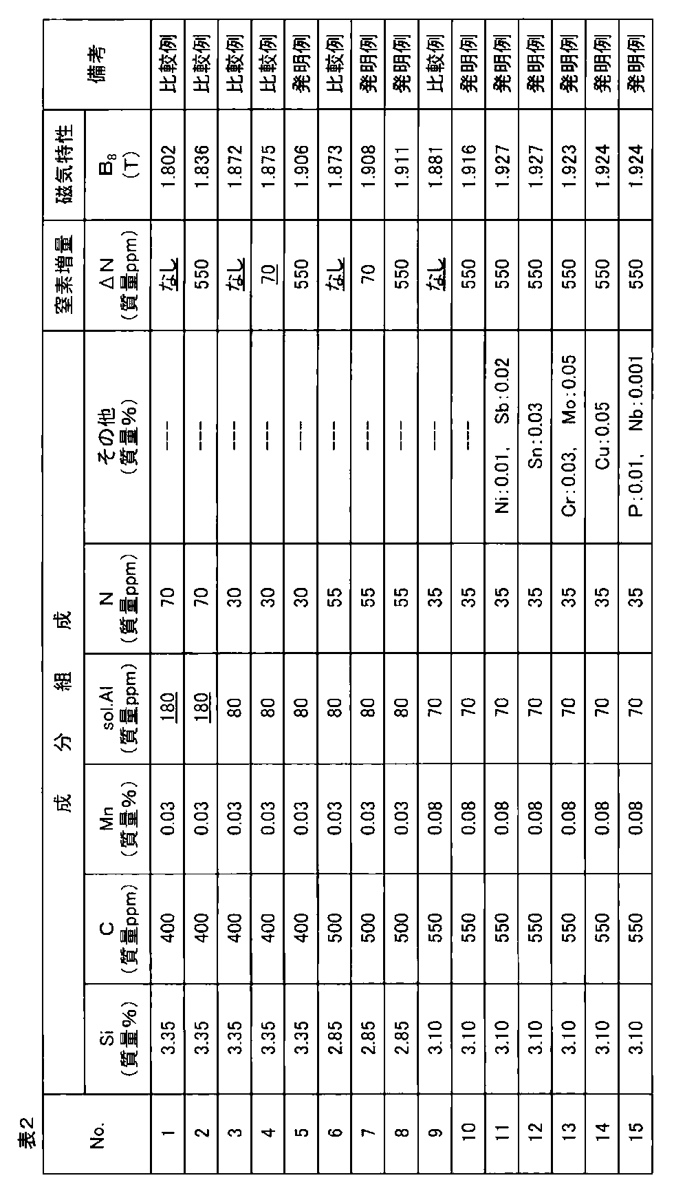
表2に示す成分を含有する鋼スラブ(但し、S,Se,O含有量はいずれも50ppm未満)を、1200℃で20分加熱後、熱間圧延により2.0mm厚の熱延板とし、1000℃,1分間の焼鈍後、冷間圧延により板厚:1.5mmまでの冷間圧延したのち、1100℃,2分間の中間焼鈍後、以下に示す冷間圧延により0.27mmの最終板厚としてから、P(H2O)/P(H2)=0.3の雰囲気下で焼鈍温度:820℃となる条件で2分間保持する脱炭焼鈍を行った。その後、一部コイルに対してバッチ処理で窒化処理(NH3雰囲気下)を行い鋼中N量を70ppmあるいは550ppm増量させたのち、MgOを主成分とし、TiO2を10%添加した焼鈍分離剤を水と混ぜてスラリ状としたものを塗布してから、コイルに巻き取り、300~800℃間の滞留時間が30時間となる昇温速度で最終仕上げ焼鈍を行い、続いてリン酸塩系の絶縁張力コーティングの塗布焼付けと鋼帯の平坦化を目的とする平坦化焼鈍を施して製品とした。
かくして得られた製品コイルからエプスタイン試験片を採取し、磁束密度B8を測定した結果を、表2に示す。
Claims (5)
- 質量%または質量ppmで、C:0.08%以下、Si:2.0~4.5%およびMn:0.5%以下を含有すると共に、S,SeおよびOをそれぞれ50ppm未満、sol.Alを100ppm未満に抑制し、さらにNを80ppm以下で、かつsol.Al(ppm)−N(ppm)×(26.98/14.00)≦30ppmを満足する範囲に制御し、残部はFeおよび不可避的不純物の組成からなる鋼スラブを、再加熱することなくまたは再加熱後、熱間圧延を施して熱延板としたのち、焼鈍および圧延によって最終板厚の冷間圧延板とし、ついで一次再結晶焼鈍前、あるいは焼鈍中または焼鈍後に窒素増量(ΔN)が下記式(1)または式(2)で規定される窒化処理を施したのち、焼鈍分離剤を塗布し、二次再結晶焼鈍を施す方向性電磁鋼板の製造方法。
記
・sol.Al−N×(26.98/14.00)≦0の場合、
50ppm≦ΔN≦1000ppm −−−(1)
・0<sol.Al−N×(26.98/14.00)≦30の場合
(N−sol.Al×14.00/26.98+100)≦ΔN≦
(N−sol.Al×14.00/26.98+1000)−−−(2) - 質量%または質量ppmで、C:0.08%以下、Si:2.0~4.5%およびMn:0.5%以下を含有すると共に、S,SeおよびOをそれぞれ50ppm未満、sol.Alを100ppm未満に抑制し、さらにNを80ppm以下で、かつsol.Al(ppm)−N(ppm)×(26.98/14.00)≦30ppmを満足する範囲に制御し、残部はFeおよび不可避的不純物の組成からなる鋼スラブを、再加熱することなくまたは再加熱後、熱間圧延を施して熱延板としたのち、焼鈍および圧延によって最終板厚の冷間圧延板とし、ついで一次再結晶焼鈍前、あるいは焼鈍中または焼鈍後に窒素増量(ΔN)が下記式(1)または式(2)で規定される窒化処理を施したのち、焼鈍分離剤を塗布し、さらに一次再結晶焼鈍から二次再結晶開始までの間に、鋼板地鉄中にNを拡散させ、粒径が100nm以上のAlを含有しない窒化珪素を析出させることによって、正常粒成長抑制力として利用する方向性電磁鋼板の製造方法。
記
・sol.Al−N×(26.98/14.00)≦0の場合
50ppm≦ΔN≦1000ppm −−−(1)
・0<sol.Al−N×(26.98/14.00)≦30の場合
(N−sol.Al×14.00/26.98+100)≦ΔN≦
(N−sol.Al×14.00/26.98+1000)−−−(2) - 前記鋼スラブが、さらに質量%で、
Ni:0.005~1.50%、 Sn:0.01~0.50%、
Sb:0.005~0.50%、 Cu:0.01~0.50%、
Cr:0.01~1.50%、 P:0.0050~0.50%、
Mo:0.01~0.50%およびNb:0.0005~0.0100%
のうちから選んだ1種または2種以上を含有する請求項1または2に記載の方向性電磁鋼板の製造方法。 - 方向性電磁鋼板製造用の一次再結晶鋼板であって、その組成が、質量%または質量ppmで、C:0.08%以下、Si:2.0~4.5%およびMn:0.5%以下を含有し、S,SeおよびOがそれぞれ50ppm未満、sol.Alが100ppm未満、Nが50ppm以上1080ppm以下で、残部はFeおよび不可避的不純物の組成範囲を満足する方向性電磁鋼板製造用の一次再結晶鋼板。
- 前記一次再結晶鋼板が、さらに質量%で、
Ni:0.005~1.50%、 Sn:0.01~0.50%、
Sb:0.005~0.50%、 Cu:0.01~0.50%、
Cr:0.01~1.50%、 P:0.0050~0.50%、
Mo:0.01~0.50%およびNb:0.0005~0.0100%
のうちから選んだ1種または2種以上を含有する請求項4に記載の方向性電磁鋼板製造用の一次再結晶鋼板。
Priority Applications (7)
| Application Number | Priority Date | Filing Date | Title |
|---|---|---|---|
| RU2015131088A RU2617308C2 (ru) | 2012-12-28 | 2013-12-25 | Способ производства текстурированного листа из электротехнической стали и первично-рекристаллизованный стальной лист для производства текстурированного листа из электротехнической стали |
| EP13867430.4A EP2940159B1 (en) | 2012-12-28 | 2013-12-25 | Production method for grain-oriented electrical steel sheet and primary recrystallized steel sheet for production of grain-oriented electrical steel sheet |
| KR1020177012516A KR101950620B1 (ko) | 2012-12-28 | 2013-12-25 | 방향성 전기 강판의 제조 방법 및 방향성 전기 강판 제조용의 1 차 재결정 강판 |
| CN201380068115.8A CN104870665B (zh) | 2012-12-28 | 2013-12-25 | 方向性电磁钢板的制造方法和方向性电磁钢板制造用的一次再结晶钢板 |
| US14/650,378 US9953752B2 (en) | 2012-12-28 | 2013-12-25 | Production method for grain-oriented electrical steel sheet and primary recrystallized steel sheet for production of grain-oriented electrical steel sheet |
| KR1020157019243A KR101977440B1 (ko) | 2012-12-28 | 2013-12-25 | 방향성 전기 강판의 제조 방법 및 방향성 전기 강판 제조용의 1 차 재결정 강판 |
| JP2014554632A JP5983777B2 (ja) | 2012-12-28 | 2013-12-25 | 方向性電磁鋼板の製造方法 |
Applications Claiming Priority (2)
| Application Number | Priority Date | Filing Date | Title |
|---|---|---|---|
| JP2012288877 | 2012-12-28 | ||
| JP2012-288877 | 2012-12-28 |
Publications (1)
| Publication Number | Publication Date |
|---|---|
| WO2014104394A1 true WO2014104394A1 (ja) | 2014-07-03 |
Family
ID=51021449
Family Applications (1)
| Application Number | Title | Priority Date | Filing Date |
|---|---|---|---|
| PCT/JP2013/085322 Ceased WO2014104394A1 (ja) | 2012-12-28 | 2013-12-25 | 方向性電磁鋼板の製造方法および方向性電磁鋼板製造用の一次再結晶鋼板 |
Country Status (7)
| Country | Link |
|---|---|
| US (1) | US9953752B2 (ja) |
| EP (1) | EP2940159B1 (ja) |
| JP (1) | JP5983777B2 (ja) |
| KR (2) | KR101950620B1 (ja) |
| CN (1) | CN104870665B (ja) |
| RU (1) | RU2617308C2 (ja) |
| WO (1) | WO2014104394A1 (ja) |
Cited By (5)
| Publication number | Priority date | Publication date | Assignee | Title |
|---|---|---|---|---|
| WO2016035345A1 (ja) * | 2014-09-04 | 2016-03-10 | Jfeスチール株式会社 | 方向性電磁鋼板の製造方法および窒化処理設備 |
| JP2016053203A (ja) * | 2014-09-04 | 2016-04-14 | Jfeスチール株式会社 | 方向性電磁鋼板の製造方法および窒化処理設備 |
| EP3214188A4 (en) * | 2014-10-30 | 2017-09-06 | JFE Steel Corporation | Production method for oriented grain-electromagnetic steel sheet |
| US9905343B2 (en) | 2012-12-28 | 2018-02-27 | Jfe Steel Corporation | Production method for grain-oriented electrical steel sheet and primary recrystallized steel sheet for production of grain-oriented electrical steel sheet |
| US10844452B2 (en) | 2015-06-09 | 2020-11-24 | Jfe Steel Corporation | Grain-oriented electrical steel sheet and method for manufacturing the same |
Families Citing this family (14)
| Publication number | Priority date | Publication date | Assignee | Title |
|---|---|---|---|---|
| CA3004286C (en) * | 2015-12-04 | 2021-05-04 | Jfe Steel Corporation | Method of producing grain-oriented electrical steel sheet |
| KR102260531B1 (ko) * | 2016-07-29 | 2021-06-03 | 제이에프이 스틸 가부시키가이샤 | 방향성 전기 강판용 열연 강판 및 그 제조 방법, 그리고 방향성 전기 강판의 제조 방법 |
| JP6572864B2 (ja) * | 2016-10-18 | 2019-09-11 | Jfeスチール株式会社 | 電磁鋼板製造用の熱延鋼板およびその製造方法 |
| WO2018207873A1 (ja) * | 2017-05-12 | 2018-11-15 | Jfeスチール株式会社 | 方向性電磁鋼板とその製造方法 |
| CN110318005B (zh) * | 2018-03-30 | 2021-12-17 | 宝山钢铁股份有限公司 | 一种高磁感取向硅钢及其制造方法 |
| WO2020145316A1 (ja) * | 2019-01-08 | 2020-07-16 | 日本製鉄株式会社 | 方向性電磁鋼板、方向性電磁鋼板の製造方法、及び、方向性電磁鋼板の製造に利用される焼鈍分離剤 |
| WO2020149346A1 (ja) | 2019-01-16 | 2020-07-23 | 日本製鉄株式会社 | 方向性電磁鋼板の製造方法 |
| EP3913096B1 (en) | 2019-01-16 | 2024-06-12 | Nippon Steel Corporation | Method for producing grain oriented electrical steel sheet |
| RU2768932C1 (ru) | 2019-01-16 | 2022-03-25 | Ниппон Стил Корпорейшн | Способ производства листа электротехнической стали с ориентированной зеренной структурой |
| KR102583079B1 (ko) | 2019-01-16 | 2023-10-04 | 닛폰세이테츠 가부시키가이샤 | 방향성 전자 강판의 제조 방법 |
| WO2020218329A1 (ja) * | 2019-04-23 | 2020-10-29 | Jfeスチール株式会社 | 方向性電磁鋼板の製造方法 |
| KR20240035910A (ko) | 2019-04-23 | 2024-03-18 | 제이에프이 스틸 가부시키가이샤 | 방향성 전자 강판의 제조 방법 |
| JP7160181B2 (ja) | 2019-09-06 | 2022-10-25 | Jfeスチール株式会社 | 方向性電磁鋼板およびその製造方法 |
| KR102325004B1 (ko) * | 2019-12-20 | 2021-11-10 | 주식회사 포스코 | 방향성 전기강판 및 그의 제조방법 |
Citations (9)
| Publication number | Priority date | Publication date | Assignee | Title |
|---|---|---|---|---|
| US1965559A (en) | 1933-08-07 | 1934-07-03 | Cold Metal Process Co | Electrical sheet and method and apparatus for its manufacture and test |
| JPS5113469B2 (ja) | 1972-10-13 | 1976-04-28 | ||
| JP2782086B2 (ja) | 1989-05-29 | 1998-07-30 | 新日本製鐵株式会社 | 磁気特性、皮膜特性ともに優れた一方向性電磁鋼板の製造方法 |
| JPH11335738A (ja) * | 1998-05-26 | 1999-12-07 | Kawasaki Steel Corp | 極めて鉄損の低い高磁束密度方向性電磁鋼板の製造方法 |
| JPH11335736A (ja) * | 1998-05-21 | 1999-12-07 | Kawasaki Steel Corp | 極めて鉄損の低い高磁束密度方向性電磁鋼板の製造方法 |
| JP2000129356A (ja) | 1998-10-28 | 2000-05-09 | Kawasaki Steel Corp | 方向性電磁鋼板の製造方法 |
| JP2001107147A (ja) * | 1999-10-12 | 2001-04-17 | Kawasaki Steel Corp | 方向性電磁鋼板の製造方法 |
| JP2006316314A (ja) * | 2005-05-12 | 2006-11-24 | Jfe Steel Kk | 磁気特性と被膜特性に優れた一方向性電磁鋼板の製造方法 |
| JP2007314823A (ja) * | 2006-05-24 | 2007-12-06 | Nippon Steel Corp | 磁束密度の高い方向性電磁鋼板の製造方法 |
Family Cites Families (17)
| Publication number | Priority date | Publication date | Assignee | Title |
|---|---|---|---|---|
| DE1252220B (ja) | 1963-04-05 | 1968-04-25 | ||
| AT329358B (de) | 1974-06-04 | 1976-05-10 | Voest Ag | Schwingmuhle zum zerkleinern von mahlgut |
| US5643370A (en) * | 1995-05-16 | 1997-07-01 | Armco Inc. | Grain oriented electrical steel having high volume resistivity and method for producing same |
| IT1290172B1 (it) * | 1996-12-24 | 1998-10-19 | Acciai Speciali Terni Spa | Procedimento per la produzione di lamierino magnetico a grano orientato, con elevate caratteristiche magnetiche. |
| KR19990088437A (ko) | 1998-05-21 | 1999-12-27 | 에모또 간지 | 철손이매우낮은고자속밀도방향성전자강판및그제조방법 |
| US6309473B1 (en) | 1998-10-09 | 2001-10-30 | Kawasaki Steel Corporation | Method of making grain-oriented magnetic steel sheet having low iron loss |
| JP4810777B2 (ja) | 2001-08-06 | 2011-11-09 | Jfeスチール株式会社 | 方向性電磁鋼板およびその製造方法 |
| KR100544537B1 (ko) | 2001-12-21 | 2006-01-24 | 주식회사 포스코 | (Al,Si,Mn)N의 복합석출물을 이용한 자기특성이우수한 저온가열 방향성 전기강판의 제조방법 |
| JP4241125B2 (ja) | 2003-03-25 | 2009-03-18 | Jfeスチール株式会社 | フォルステライト被膜を有しない方向性電磁鋼板の製造方法 |
| EP1752548B1 (de) | 2005-08-03 | 2016-02-03 | ThyssenKrupp Steel Europe AG | Verfahren zur Herstellung von kornorientiertem Elektroband |
| EP1752549B1 (de) | 2005-08-03 | 2016-01-20 | ThyssenKrupp Steel Europe AG | Verfahren zur Herstellung von kornorientiertem Elektroband |
| KR101062127B1 (ko) * | 2006-05-24 | 2011-09-02 | 신닛뽄세이테쯔 카부시키카이샤 | 자속 밀도가 높은 방향성 전자기 강판의 제조 방법 |
| JP5754097B2 (ja) | 2010-08-06 | 2015-07-22 | Jfeスチール株式会社 | 方向性電磁鋼板およびその製造方法 |
| JP5853352B2 (ja) | 2010-08-06 | 2016-02-09 | Jfeスチール株式会社 | 方向性電磁鋼板およびその製造方法 |
| MX2013002627A (es) | 2010-09-10 | 2013-04-24 | Jfe Steel Corp | Lamina de acero magnetica de grano orientado y proceso para producir la misma. |
| JP5994981B2 (ja) * | 2011-08-12 | 2016-09-21 | Jfeスチール株式会社 | 方向性電磁鋼板の製造方法 |
| KR101949626B1 (ko) | 2012-12-28 | 2019-02-18 | 제이에프이 스틸 가부시키가이샤 | 방향성 전기 강판의 제조 방법 및 방향성 전기 강판 제조용의 1 차 재결정 강판 |
-
2013
- 2013-12-25 US US14/650,378 patent/US9953752B2/en active Active
- 2013-12-25 JP JP2014554632A patent/JP5983777B2/ja active Active
- 2013-12-25 KR KR1020177012516A patent/KR101950620B1/ko active Active
- 2013-12-25 CN CN201380068115.8A patent/CN104870665B/zh active Active
- 2013-12-25 KR KR1020157019243A patent/KR101977440B1/ko active Active
- 2013-12-25 WO PCT/JP2013/085322 patent/WO2014104394A1/ja not_active Ceased
- 2013-12-25 RU RU2015131088A patent/RU2617308C2/ru active
- 2013-12-25 EP EP13867430.4A patent/EP2940159B1/en active Active
Patent Citations (9)
| Publication number | Priority date | Publication date | Assignee | Title |
|---|---|---|---|---|
| US1965559A (en) | 1933-08-07 | 1934-07-03 | Cold Metal Process Co | Electrical sheet and method and apparatus for its manufacture and test |
| JPS5113469B2 (ja) | 1972-10-13 | 1976-04-28 | ||
| JP2782086B2 (ja) | 1989-05-29 | 1998-07-30 | 新日本製鐵株式会社 | 磁気特性、皮膜特性ともに優れた一方向性電磁鋼板の製造方法 |
| JPH11335736A (ja) * | 1998-05-21 | 1999-12-07 | Kawasaki Steel Corp | 極めて鉄損の低い高磁束密度方向性電磁鋼板の製造方法 |
| JPH11335738A (ja) * | 1998-05-26 | 1999-12-07 | Kawasaki Steel Corp | 極めて鉄損の低い高磁束密度方向性電磁鋼板の製造方法 |
| JP2000129356A (ja) | 1998-10-28 | 2000-05-09 | Kawasaki Steel Corp | 方向性電磁鋼板の製造方法 |
| JP2001107147A (ja) * | 1999-10-12 | 2001-04-17 | Kawasaki Steel Corp | 方向性電磁鋼板の製造方法 |
| JP2006316314A (ja) * | 2005-05-12 | 2006-11-24 | Jfe Steel Kk | 磁気特性と被膜特性に優れた一方向性電磁鋼板の製造方法 |
| JP2007314823A (ja) * | 2006-05-24 | 2007-12-06 | Nippon Steel Corp | 磁束密度の高い方向性電磁鋼板の製造方法 |
Cited By (8)
| Publication number | Priority date | Publication date | Assignee | Title |
|---|---|---|---|---|
| US9905343B2 (en) | 2012-12-28 | 2018-02-27 | Jfe Steel Corporation | Production method for grain-oriented electrical steel sheet and primary recrystallized steel sheet for production of grain-oriented electrical steel sheet |
| WO2016035345A1 (ja) * | 2014-09-04 | 2016-03-10 | Jfeスチール株式会社 | 方向性電磁鋼板の製造方法および窒化処理設備 |
| JP2016053203A (ja) * | 2014-09-04 | 2016-04-14 | Jfeスチール株式会社 | 方向性電磁鋼板の製造方法および窒化処理設備 |
| JPWO2016035345A1 (ja) * | 2014-09-04 | 2017-04-27 | Jfeスチール株式会社 | 方向性電磁鋼板の製造方法および窒化処理設備 |
| US10900113B2 (en) | 2014-09-04 | 2021-01-26 | Jfe Steel Corporation | Method for manufacturing grain-oriented electrical steel sheet, and nitriding apparatus |
| US11761074B2 (en) | 2014-09-04 | 2023-09-19 | Jfe Steel Corporation | Nitriding apparatus for manufacturing a grain-oriented electrical steel sheet |
| EP3214188A4 (en) * | 2014-10-30 | 2017-09-06 | JFE Steel Corporation | Production method for oriented grain-electromagnetic steel sheet |
| US10844452B2 (en) | 2015-06-09 | 2020-11-24 | Jfe Steel Corporation | Grain-oriented electrical steel sheet and method for manufacturing the same |
Also Published As
| Publication number | Publication date |
|---|---|
| JP5983777B2 (ja) | 2016-09-06 |
| EP2940159B1 (en) | 2019-03-20 |
| EP2940159A1 (en) | 2015-11-04 |
| US9953752B2 (en) | 2018-04-24 |
| KR20150096752A (ko) | 2015-08-25 |
| KR101950620B1 (ko) | 2019-02-20 |
| KR101977440B1 (ko) | 2019-05-10 |
| EP2940159A4 (en) | 2016-04-13 |
| CN104870665A (zh) | 2015-08-26 |
| RU2015131088A (ru) | 2017-02-01 |
| RU2617308C2 (ru) | 2017-04-24 |
| JPWO2014104394A1 (ja) | 2017-01-19 |
| US20150318094A1 (en) | 2015-11-05 |
| KR20170054578A (ko) | 2017-05-17 |
| CN104870665B (zh) | 2018-09-21 |
Similar Documents
| Publication | Publication Date | Title |
|---|---|---|
| JP5983777B2 (ja) | 方向性電磁鋼板の製造方法 | |
| JP5692479B2 (ja) | 方向性電磁鋼板の製造方法 | |
| JP5983776B2 (ja) | 方向性電磁鋼板の製造方法 | |
| JP5857983B2 (ja) | 方向性電磁鋼板の製造方法および焼鈍分離剤用MgO | |
| JP5907202B2 (ja) | 方向性電磁鋼板の製造方法 | |
| JP6011586B2 (ja) | 方向性電磁鋼板の製造方法 | |
| JP5939156B2 (ja) | 方向性電磁鋼板の製造方法 | |
| JP5928362B2 (ja) | 方向性電磁鋼板の製造方法および方向性電磁鋼板製造用の一次再結晶鋼板 | |
| JP6209999B2 (ja) | 方向性電磁鋼板の製造方法 | |
| JP5853968B2 (ja) | 方向性電磁鋼板の製造方法 | |
| JP5999040B2 (ja) | 方向性電磁鋼板の製造方法 | |
| JP5904151B2 (ja) | 方向性電磁鋼板の製造方法 | |
| JP6209998B2 (ja) | 方向性電磁鋼板の製造方法 | |
| JP6036587B2 (ja) | 方向性電磁鋼板の製造方法および方向性電磁鋼板製造用の一次再結晶鋼板 |
Legal Events
| Date | Code | Title | Description |
|---|---|---|---|
| 121 | Ep: the epo has been informed by wipo that ep was designated in this application |
Ref document number: 13867430 Country of ref document: EP Kind code of ref document: A1 |
|
| ENP | Entry into the national phase |
Ref document number: 2014554632 Country of ref document: JP Kind code of ref document: A |
|
| WWE | Wipo information: entry into national phase |
Ref document number: 14650378 Country of ref document: US |
|
| WWE | Wipo information: entry into national phase |
Ref document number: 2013867430 Country of ref document: EP |
|
| NENP | Non-entry into the national phase |
Ref country code: DE |
|
| ENP | Entry into the national phase |
Ref document number: 20157019243 Country of ref document: KR Kind code of ref document: A |
|
| ENP | Entry into the national phase |
Ref document number: 2015131088 Country of ref document: RU Kind code of ref document: A |